EP3926084A1 - Strickmaschine und fehlererkennungssystem - Google Patents
Strickmaschine und fehlererkennungssystem Download PDFInfo
- Publication number
- EP3926084A1 EP3926084A1 EP21178777.5A EP21178777A EP3926084A1 EP 3926084 A1 EP3926084 A1 EP 3926084A1 EP 21178777 A EP21178777 A EP 21178777A EP 3926084 A1 EP3926084 A1 EP 3926084A1
- Authority
- EP
- European Patent Office
- Prior art keywords
- image
- stitch
- knitting
- needle
- stitches
- Prior art date
- Legal status (The legal status is an assumption and is not a legal conclusion. Google has not performed a legal analysis and makes no representation as to the accuracy of the status listed.)
- Granted
Links
Images




Classifications
-
- D—TEXTILES; PAPER
- D04—BRAIDING; LACE-MAKING; KNITTING; TRIMMINGS; NON-WOVEN FABRICS
- D04B—KNITTING
- D04B35/00—Details of, or auxiliary devices incorporated in, knitting machines, not otherwise provided for
- D04B35/10—Indicating, warning, or safety devices, e.g. stop motions
- D04B35/20—Indicating, warning, or safety devices, e.g. stop motions responsive to defects, e.g. holes, in knitted products
-
- D—TEXTILES; PAPER
- D04—BRAIDING; LACE-MAKING; KNITTING; TRIMMINGS; NON-WOVEN FABRICS
- D04B—KNITTING
- D04B15/00—Details of, or auxiliary devices incorporated in, weft knitting machines, restricted to machines of this kind
- D04B15/10—Needle beds
-
- D—TEXTILES; PAPER
- D04—BRAIDING; LACE-MAKING; KNITTING; TRIMMINGS; NON-WOVEN FABRICS
- D04B—KNITTING
- D04B35/00—Details of, or auxiliary devices incorporated in, knitting machines, not otherwise provided for
- D04B35/10—Indicating, warning, or safety devices, e.g. stop motions
-
- D—TEXTILES; PAPER
- D04—BRAIDING; LACE-MAKING; KNITTING; TRIMMINGS; NON-WOVEN FABRICS
- D04B—KNITTING
- D04B37/00—Auxiliary apparatus or devices for use with knitting machines
- D04B37/02—Auxiliary apparatus or devices for use with knitting machines with weft knitting machines
-
- D—TEXTILES; PAPER
- D06—TREATMENT OF TEXTILES OR THE LIKE; LAUNDERING; FLEXIBLE MATERIALS NOT OTHERWISE PROVIDED FOR
- D06H—MARKING, INSPECTING, SEAMING OR SEVERING TEXTILE MATERIALS
- D06H3/00—Inspecting textile materials
- D06H3/08—Inspecting textile materials by photo-electric or television means
Definitions
- the disclosure relates to a technique of a knitting machine and a defect detection system capable of detecting defective knitting of a knitted fabric.
- a convention technique of detecting defective knitting of a knitted fabric is known.
- the technique is disclosed in, for example, JP S57-183469 A .
- JP S57-183469 A discloses a technique of comparing an image of a knit fabric acquired using an image capturer with an image of a normal knit fabric stored in advance in a storage and detecting presence or absence of occurrence of defective knitted fabric (knitting defect).
- JP S57-183469 A is configured to detect a defect of a completed knit fabric, and thus unnecessary cost (power, yarn, knitting time, and the like of a knitting machine that has knitted the knit fabric) occurs.
- a defective knitted fabric may be difficult to detect even if the fabric is imaged.
- the disclosure has been made in view of the above circumstances, and an object of the disclosure is to provide a knitting machine and a defect detection system capable of detecting defective knitting at an early stage and with high accuracy.
- a knitting machine of the disclosure includes a knitting needle configured to knit a knitted fabric, an image capturer configured to image a stitch held on the knitting needle, a determiner configured to compare a state of the stitch imaged by the image capturer with a state of the stitch in a normal state and perform a quality determination of the stitch, and a position storage configured to store a position of the stitch imaged by the image capturer.
- This configuration allows defective knitting to be detected at an early stage and with high accuracy.
- the knitting needle may be disposed at each of needle beds disposed so as to face each other across a needle bed gap, and the image capturer may image a stitch held on the knitting needle from above the needle bed gap of the needle beds disposed to face each other.
- This configuration allows stitches to be easily imaged, and eventually, defective knitting to be accurately detected.
- the image capturer may capture, from a first side of the needle beds disposed to face each other, an image of a stitch held on the knitting needle disposed at a second side of the needle beds.
- This configuration allows stitches to be more easily imaged and allows defective knitting to be more accurately detected.
- the image capturer may be provided so as to be movable along the needle beds.
- This configuration allows stitches at a plurality of places can be imaged by one image capturer.
- the image capturer may be fixed at such a position as to image a stitch held on the knitting needle, and may image the stitch in association with a timing of formation of the stitch with the knitting needle.
- This configuration can simplify the configuration. Further, an image of the stitches can be acquired at an appropriate timing.
- a defect detection system of the disclosure includes an image capturer configured to image a stitch held on the knitting needle configured to knit a knitted fabric, a determiner configured to compare a state of the stitch imaged by the image capturer with a state of the stitch in a normal state and perform a quality determination of the stitch, and a position storage configured to store a position of the stitch imaged by the image capturer.
- This configuration allows defective knitting to be detected at an early stage and with high accuracy.
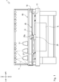
- the flat knitting machine 1 mainly includes a needle bed 10, a carriage 20, a yarn guide rail 30, a servomotor 40, a yarn stand base 50, and a controller 60.
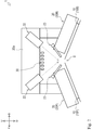
- the needle beds 10 illustrated in Figs. 1 to 3 are disposed so as to face each other across a needle bed gap S at the front and rear.
- the front and rear needle beds 10 are disposed in an inverted V shape in a side view so as to be inclined upward toward a center in the front and rear direction (direction facing each other) (see Fig. 2 ).
- Each of the needle beds 10 is provided with a large number of knitting needles 11 disposed side by side along a longitudinal direction (left and right direction) of each of the needle beds 10.
- the front and rear needle beds 10 can relatively move to the left and right when delivering and receiving (transferring) of a stitch are carried out between the front and rear needle beds 10.
- a pair of front and rear carriages 20 are disposed to face the front and rear needle beds 10 from above.
- the front and rear carriages 20 are connected by a bridge 20a disposed to straddle the plurality of yarn guide rails 30.
- the carriages 20 can reciprocate along the longitudinal direction of the needle beds 10 by the servomotor 40 (see Fig. 4 ).
- the carriages 20 are provided with a needle selecting mechanism (not shown) and a cam mechanism 21 for selectively operating the knitting needles 11 of the needle beds 10.
- Each of the carriages 20 is also provided with an image capturer 22 and an illuminator 23 for imaging stitch held on the knitting needles 11.
- the plurality of yarn guide rails 30 shown in Figs. 1 and 2 are disposed above the needle bed gap S so as to extend along the longitudinal direction of the needle beds 10.
- a yarn carrier 31 (see Fig. 1 ) configured to feed a knitting yarn Y is supported on the yarn guide rails 30 so as to be movable.
- the yarn stand base 50 illustrated in Fig. 1 is provided with a yarn cone 51 around which the knitting yarn Y is wound.
- the knitting yarn Y from the yarn cone 51 is fed to the yarn carrier 31 through an appropriate yarn feeding path.
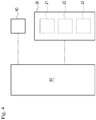
- the controller 60 shown in Fig. 4 is configured to control an operation of the flat knitting machine 1.
- the controller 60 includes a calculation processor such as a CPU (central processing unit) and a storage such as a RAM (random access memory) and a ROM (read only memory).
- the storage of the controller 60 stores various information, programs, and the like used for controlling the flat knitting machine 1.
- the controller 60 is provided at an appropriate location (for example, in a body of the flat knitting machine 1 (below the rear needle bed 10) of the flat knitting machine 1.
- the controller 60 is connected to the servomotor 40 and can control an operation of the servomotor 40.
- the controller 60 can arbitrarily move the carriages 20 by controlling the operation of the servomotor 40.
- the controller 60 can detect a position of the carriages 20 on the basis of a rotational speed of the servomotor 40.
- the controller 60 is connected to the carriages 20 (specifically, the cam mechanism 21, the image capturers 22, and the illuminators 23) and can control an operation of the carriages 20.
- the controller 60 controls each part of the flat knitting machine 1 on the basis of knitting data created in advance and the like. Specifically, the controller 60 can reciprocate the carriages 20 along the longitudinal direction of the needle beds 10 by controlling the operation of the servomotor 40. In this case, knitting operations such as knit, tuck, miss, and the like, and the transfer of the stitches between the front and rear needle beds 10 can be performed by moving the knitting needles 11 forward and rearward with respect to the needle bed gap S by the cam mechanism 21 and the like mounted on the carriages 20. A knitted fabric K is knitted by repeating such reciprocating movement of the carriages 20.
- the controller 60 can image stitches held on the knitting needles 11 with the image capturers 22.
- the controller 60 can detect a defective knitting on the basis of an image (shape of the stitch) imaged by the image capturers 22.
- the front needle bed 10 may be referred to as a front needle bed 10F
- the rear needle bed 10 may be referred to as a rear needle bed 10B
- the front carriage 20 may be referred to as a front carriage 20F
- the rear carriage 20 may be referred to as a rear carriage 20B.
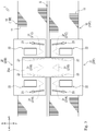
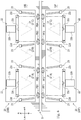
- the front carriage 20F is provided with three cam mechanisms 21 for advancing and retracting the knitting needles 11. Specifically, a first transfer cam mechanism 21A, a knit cam mechanism 21B, and a second transfer cam mechanism 21C are disposed along a moving direction (left and right direction) of the carriages 20.
- the knit cam mechanism 21B is configured to form stitches using the knitting yarn Y fed from the yarn carrier 31.
- the first transfer cam mechanism 21A and the second transfer cam mechanism 21C are configured to transfer stitches between the knitting needles 11 of the front and rear needle beds 10.
- the first transfer cam mechanism 21A, the knit cam mechanism 21B, and the second transfer cam mechanism 21C are disposed in that order from left to right.
- Each of the cam mechanisms 21 can guide butts of the knitting needles 11 selected on the basis of knitting data along an advancing and retracting track L to advance and retract the knitting needles 11.
- the stitches using the knitting yarn Y can be formed and transferred.
- the knit cam mechanism 21B serves as a preceding system and forms stitches.
- the first transfer cam mechanism 21A serves as a succeeding system and transfers the stitches formed by the knit cam mechanism 21B.
- the second transfer cam mechanism 21C does not transfer the stitches.
- the knit cam mechanism 21B serves as the preceding system and forms the stitches.
- the second transfer cam mechanism 21C serves as a succeeding system and transfers the stitches formed by the knit cam mechanism 21B.
- the first transfer cam mechanism 21A does not transfer the stitches.
- each cam mechanism 21 is an example, and stitches can be transferred, formed, and then transferred sequentially using, for example, three cam mechanisms 21.
- the front carriage 20F has been described with reference to Fig. 5 , but as illustrated in Fig. 6 , the rear carriage 20B is substantially longitudinally symmetric with the front carriage 20F (includes the first transfer cam mechanism 21A and the like similarly to the front carriage 20F), and thus a detailed description of the rear carriage 20B will be omitted.
- each of the image capturers 22 mainly includes a support member 22a, a camera 22b, a center prism 22c, and side prisms 22d.
- the support member 22a supports the camera 22b, the center prism 22c, and the side prisms 22d.
- the support member 22a includes a plate-like member.
- the support member 22a is formed in an appropriate shape so as to be able to support the camera 22b, the center prism 22c, and the side prisms 22d at predetermined positions.
- the camera 22b is a device for acquiring an image.
- the camera 22b is fixed to the support member 22a with a lens 22e oriented in a predetermined direction.
- the center prism 22c guides light from two directions to the lens 22e of the camera 22b.
- the center prism 22c is disposed in front of the lens 22e (in a direction toward which the lens 22e is directed).
- the center prism 22c reflects light from sides (an up and down direction in Fig. 7A ) and guides the light to the lens 22e.
- the side prisms 22d guide light from predetermined directions to the center prism 22c.
- a pair of the side prisms 22d (a pair in the up and down direction in Fig. 7A ) are provided with the center prism 22c interposed therebetween.
- the side prisms 22d reflect light from a front (the right in Fig. 7A ) and guide the light to the center prism 22c.
- the image capturers 22 configured as described above, light from the front of the pair of side prisms 22d is appropriately guided by the side prisms 22d and the center prism 22c and enters the lens 22e of the camera 22b. As a result, the image capturers 22 acquire images of two different locations (front surfaces of the two side prisms 22d) by one camera 22b.
- the image capturers 22 are disposed above the needle bed gap S of the needle beds 10.
- the front and rear carriages 20 are provided with a total of four image capturers 22. Specifically, two image capturers 22 are disposed on each of the front and rear with the needle bed gap S interposed therebetween.
- the image capturers 22 are fixed to the carriages 20 directly or indirectly (through the bridge 20a or another appropriate member).
- the image capturers 22 provided on the carriages 20 which are movable allows imaging to be performed with the image capturers 22 moving together with the carriages 20, and thus, imaging can be performed at a plurality of locations by a single image capturer 22, for example.
- the image capturers 22 are disposed above the front carriage 20F.
- the image capturers 22 are disposed such that an imaging direction (lens 22e) faces rear-downward.
- the image capturers 22 can image distal ends (specifically, stitches held on the knitting needles 11) of the knitting needles 11 of the rear needle bed 10B.
- the shape of stitches can be easily and clearly imaged by imaging the knitting needles 11 of the rear needle bed 10B from above the needle bed gap S.
- the shape of the stitches can be easily imaged more clearly, and eventually, defective knitting described later can be accurately detected.
- the two image capturers 22 disposed in front of the needle bed gap S are disposed so as to correspond to positions in the left and right of the cam mechanism 21.
- the image capturers 22 are disposed at substantially the same position in the left and right direction as the first transfer cam mechanism 21A and the second transfer cam mechanism 21C.
- the side prisms 22d of the image capturers 22 are disposed to be located to the left and right of the cam mechanism 21, respectively.
- the two image capturers 22 can image four imaging points (rear first imaging point PB1, rear second imaging point PB2, rear third imaging point PB3, and rear fourth imaging point PB4) of the rear needle bed 10B.
- the rear first imaging point PB1 is set to be located to the left of the first transfer cam mechanism 21A.
- the rear second imaging point PB2 is set so as to be located to the right of the first transfer cam mechanism 21A and to the left of the knit cam mechanism 21B.
- the rear third imaging point PB3 is set to be located to the right of the knit cam mechanism 21B and to the left of the second transfer cam mechanism 21C.
- the rear fourth imaging point PB4 is set to be located to the right of the second transfer cam mechanism 21C.
- the two image capturers 22 disposed behind the needle bed gap S are disposed symmetrically in the front and rear direction with the image capturers 22 disposed at the front across the needle bed gap S, and thus a detailed description of the two image capturers 22 will be omitted.
- the two image capturers 22 disposed behind the needle bed gap S can image four imaging points (front first imaging point PF1, front second imaging point PF2, front third imaging point PF3, and front fourth imaging point PF4) of the front needle bed 10F.
- Left and right positions of the four front imaging points PF1 to PF4 are also similar to those of the four rear imaging points PB1 to PB4, and thus detailed description will be omitted.
- a total of eight imaging points can be imaged using the four image capturers 22.
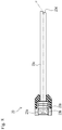
- each of the illuminators 23 mainly includes a light emitting diode (LED) 23a, condenser lenses 23b, and a guide 23c.
- LED light emitting diode
- the LED 23a is a light source that emits light when a voltage is applied.
- the LED 23a can emit light in a predetermined direction (to the right in Fig. 8 ).
- the condenser lenses 23b are configured to collect light emitted from the LED 23a.
- the condenser lenses 23b are disposed in front of the LED 23a (to the right in Fig. 8 ). In the embodiment, two condenser lenses 23b are disposed.
- the guide 23c guides the light emitted from the LED 23a to a predetermined position.
- the guide 23c is formed with a material (acrylic or the like) having translucency.
- the guide 23c is formed in a longitudinal shape extending along an irradiation direction of light from the LED 23a (the left and right direction in Fig. 8 ).
- a distal end surface 23d (end surface opposite to the LED 23a) of the guide 23c is formed in an inclined surface cut obliquely. Specifically, the distal end surface 23d is formed so as to be inclined with respect to a direction perpendicular to the longitudinal direction of the guide 23c.
- the illuminator 23 configured as described above, when light is emitted from the LED 23a, the light enters the guide 23c through the condenser lenses 23b.
- the light entering the guide 23c travels along the longitudinal direction of the guide 23c, and is emitted from the distal end surface 23d to outside of the guide 23c.
- the light is refracted at an angle corresponding to an inclination angle of the distal end surface 23d.
- the carriages 20 are provided with a total of eight illuminators 23. Specifically, four illuminators 23 are disposed at each of the front and rear with the needle bed gap S interposed therebetween. The illuminators 23 are fixed to the carriages 20 directly or indirectly (through the bridge 20a or another appropriate member).
- the illuminators 23 are disposed such that the irradiation direction of the light (the distal end surface 23d of the guide 23c) faces rear-downward.
- the illuminators 23 can irradiate the distal ends (specifically, the stitches held on the knitting needles 11) of the knitting needles 11 of the rear needle bed 10B with light.
- the four illuminators 23 disposed in front of the needle bed gap S are disposed so as to be able to irradiate the four imaging points PB1 to PB4 of the rear needle bed 10B with light.
- the four illuminators 23 disposed behind the needle bed gap S are disposed symmetrically in the front and rear direction with the illuminators 23 disposed at the front across the needle bed gap S, and thus a detailed description of the four illuminators 23 will be omitted.
- the four illuminators 23 disposed behind the needle bed gap S are disposed so as to be able to irradiate the four imaging points PF1 to PF4 of the front needle bed 10F with light as illustrated in Fig. 6 .
- Fig. 9 illustrates, as an example, the image capturer 22 that images the front first imaging point PF1 and the front second imaging point PF2, and the two illuminators 23 that irradiate the front first imaging point PF1 and the front second imaging point PF2 with light.
- the illuminators 23 are disposed to sides of a visual field of the image capturer 22 and irradiate the imaging points with light.
- the distal end surfaces 23d of the illuminators 23 are formed so as to refract the light emitted from the guides 23c.
- the illuminators 23 are disposed such that light is refracted toward the imaging points.
- the illuminators 23 can be disposed outside the visual field of the image capturer 22 (out of the visual field), and the illuminators 23 can be prevented from avoiding the imaging of the image capturer 22.
- the controller 60 can detect defective knitting by performing a quality determination of the stitches on the basis of the image of the stitches imaged by the image capturers 22.
- a method of detecting defective knitting by the controller 60 will be described.
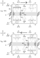
- the controller 60 carries out the imaging by the image capturers 22 in synchronization with the reciprocating movement of the carriages 20 during the knitting of the knitted fabric K. Specifically, when the knitting needles 11 to be imaged reach the imaging points by the movement of the carriage 20, the controller 60 causes the illuminators 23 to irradiate the stitches held on the knitting needles 11 with light and causes the image capturers 22 to image the stitches.
- the controller 60 can recognize the position of the carriages 20 from the rotational speed of the servomotor 40, and thus the imaging can be performed at an appropriate timing in accordance with the position of the stitches (knitting needles 11).
- the controller 60 images all the knitting needles 11 (stitches) during the knitting. At this time, the controller 60 stores the imaged position of the stitches.
- a defect associated with the knitting may occur to the knitting needles 11 after passing through the knit cam mechanism 21B and the knitting needles 11 after passing through the first transfer cam mechanism 21A.
- the controller 60 images only four imaging points including the front first imaging point PF1, the front second imaging point PF2, the rear first imaging point PB1, and the rear second imaging point PB2. That is, when the carriages 20 move to the right, the controller 60 images the stitches using only the two image capturers 22 disposed on the left.
- the controller 60 images only four imaging points including the front third imaging point PF3, the front fourth imaging point PF4, the rear third imaging point PB3, and the rear fourth imaging point PB4. That is, when the carriages 20 move to the left, the controller 60 images the stitches using only the two image capturers 22 disposed on the right.
- control of the image capturers 22 is an example, and all the imaging points can be imaged using all the four image capturers 22, for example.
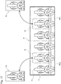
- the controller 60 images all the stitches of each course and stores the position of the imaged stitches while the knitted fabric K is being knitted, as shown in Fig. 11 .
- controller 60 performs the quality determination of the stitches of a previous course during the knitting of each course.
- a method of performing the quality determination of a stitch will be described.
- Fig. 12 illustrates an example of an image P of the stitches imaged by the image capturers 22.
- Fig. 12 illustrates an example of the image P obtained by imaging the front first imaging point PF1 and the front second imaging point PF2.
- the controller 60 extracts a region (determination region R) where a stitch to be determined is shown from each of the front first imaging point PF1 and the front second imaging point PF2.
- the controller 60 can extract an appropriate determination region R on the basis of information of the image P. For example, a position of the distal end of each knitting needle 11 can be detected on the basis of luminance of the image P, and the determination region R can be extracted on the basis of the position of the distal end of each knitting needle 11.
- the controller 60 compares the shape of the stitch shown in the determination region R (actually imaged) with a shape of a stitch at a normal state stored in advance, and performs the quality determination of the stitch.
- the controller 60 has stored an image (normal image N) showing the shape of the stitch at the normal state in advance.
- the shape of the stitch at the normal state differs in accordance with a type of stitch (knit, miss, tuck, or the like), a type of knitting yarn Y, the adjacent stitches (for example, the type and presence or absence of the stitches that have been formed until the previous course and the stitches on the right and left), and the like. Therefore, the controller 60 has stored a large number of normal images N of various patterns in advance.
- the controller 60 determines the shape of stitch that may be held on the knitting needle 11 of the imaged image in consideration of the type of the stitch, the type of the knitting yarn Y, the adjacent stitch, and the like described above on the basis of the knitting data of the knitted fabric K that is being currently knitted and the position of the imaged stitch.
- the controller 60 extracts a normal image N suitable for the quality determination (corresponding to the shape of the imaged stitch) from the stored various normal images N and uses the normal image N for the quality determination of the stitch.
- the controller 60 performs the quality determination of the stitch by performing image processing using the image of the determination region R and the normal image N. For example, the controller 60 calculates a similarity between the shape of the stitch in the determination region R and the shape of the stitch shown in the normal image N, and when the similarity is high to some extent (greater than or equal to a predetermined threshold value), the controller can determine that the stitch in the determination region R is normal.
- the controller 60 can determine that the stitch in the determination region R is abnormal when the similarity is low to some extent (less than the predetermined threshold value).
- Various states such as a state in which the knitting yarn Y is broken, a state in which a stitch (loop) is not formed, and a state in which the stitch is excessively clogged are assumed as the abnormality of the stitch.
- the quality determination of the stitches can be performed by comparing RGB values, luminance, and the like of the determination region R and the normal image N.
- the quality determination of the stitches can also be performed, for example, by extracting a core wire of the knitting yarn Y (line passing through a center of the knitting yarn Y) forming a stitch from an image and comparing (calculating similarity) a shape of the core wire and a shape of the core wire at a normal state without using the luminance or the like.
- the controller 60 quickly performs the quality determination of the stitches as described above after imaging the image P. Specifically, as shown in Fig. 11 , the controller 60 performs the quality determination of the image imaged in a certain course (for example, N course) during knitting of the next course (N + 1 course). Thus, if a defect occurs in the stitch, the defect can be detected immediately after (during the knitting of the next course).
- a certain course for example, N course
- the controller 60 can quickly stop the operation of the carriages 20 and interrupt the knitting by the flat knitting machine 1 upon detection of the defect of the stitch. Timing of the quality determination of the stitches is not limited to this timing, and for example, the quality determination of the image imaged in a certain course can be performed in real time during the knitting of the course.
- the controller 60 stores a position where the defect is detected (position of the knitting needles 11).
- the position can be recognized on the basis of the position of the carriages 20 when the image P is acquired. By storing the position, not only presence or absence of the occurrence of a defect but also an occurrence location of the defect can be recognized.
- the controller 60 can also show the image of the stitch at the position where the defect is detected (or where a defect is suspected) on a display such as a monitor to allow an operator to confirm.
- the stitch held on the knitting needles 11 can be imaged, and a defect can be detected from the imaged image. That is, the presence or absence of a defect can be found during the knitting of the knitted fabric K, and thus defective knitting can be detected at an early stage. Thus, measures such as interruption of the knitting can be promptly taken, and unnecessary costs (power of flat knitting machine 1 for knitting the knitted fabric K, knitting yarn Y, knitting time, and the like) can be suppressed.
- the shape of each stitch can be more accurately checked, and eventually the defect can be accurately detected by performing the quality determination of the shape of each stitch held on the knitting needles 11 instead of performing the quality determination on the knitted fabric K after the knitting.
- the defect of the knitted fabric rib knitted fabric, knitted fabric of stretch yarn, and the like
- the defect of the knitted fabric can also be accurately detected.
- controller 60 is one embodiment of a determiner and a position storage according to the disclosure.
- the flat knitting machine 1 has been described as an example of the knitting machine, but the disclosure is not limited to the flat knitting machine 1, and can be applied to other various knitting machines (for example, a circular knitting machine, a warp knitting machine, and the like). That is, the defective knitting can be detected by providing the image capturer capable of imaging the stitches held on the knitting needles of various knitting machines.
- the image imaged by the image capturers 22 can also be used for purposes other than detection of defective knitting.
- the knitted fabric K that is generally knitted is pulled down by a wind-down roller or the like, but can also be used for controlling the wind-down roller (controlling of a pull-down tension of the knitted fabric K).
- the knitted fabric K rises at the needle bed gap S. Then, presence or absence of rising of the knitted fabric K is determined from the image imaged by the image capturers 22, and the pull-down tension of the winding-down roller is increased if the knitted fabric K has risen. This can suppress the occurrence of defects.
- the flat knitting machine 1 can also be stopped upon determination that a defect obviously has occurred due to the rising of the knitted fabric K. The flat knitting machine 1 can also be stopped upon determination that a defect obviously has occurred by rising of the fabric.
- the image capturers 22 can be provided on a moving body (moving body movable along the longitudinal direction of the needle beds 10) provided separately from the carriages 20.
- the image capturers 22 may be provided on a moving body movable along the yarn guide rail 30.
- the image capturers 22 are configured to be movable, but the disclosure is not limited to this configuration, and the image capturers 22 can be dispose (fixed) to be unmovable.
- the image capturers 22 can be fixed at a position where the stitches can be imaged, such as above the needle bed gap S.
- an entire range of the needle beds 10 in the longitudinal direction may be imaged by one image capturer 22 or may be imaged at a plurality of places by using a plurality of image capturers 22.
- the stitches are desirably imaged with the image capturer 22 in association with timing of formation of the stitches with the knitting needle 11.
- the knitting needles 11 after passing through the preceding system and the succeeding system are desirably imaged by interlocking the timing of imaging with the position of the carriages 20.
- the image of the stitch can be acquired at an appropriate timing (after the knitting is completed) by imaging the stitch in association with the timing of formation of the stitch by the knitting needles 11.
- the image capturers 22 are disposed above the carriages 20, and the stitches are imaged from above the needle beds 10, but the disclosure is not limited to this configuration.
- the image capturers 22 can be disposed below the needle beds 10, and the stitches may be imaged from below the needle beds 10.
- the image capturers 22 can be disposed above and below the needle beds 10, and the stitches may be imaged both from above and from below the needle beds 10.
- the shape of a stitch can be more accurately recognized and a detection accuracy of a defect can be improved by imaging the same stitch from a plurality of directions.
- the illuminators 23 can also be provided on a moving body other than the carriages 20. Further, the illuminators 23 can be also disposed (fixed) so as to be unmovable. The illuminators 23 can be disposed below (or both above and below) the needle beds 10, and light can be irradiated from below the needle beds 10 toward the stitches. Further, the illuminators 23 can be provided outside the carriages 20, and the carriages 20 can be provided with an appropriate reflecting member (mirror or the like) to guide the light emitted from outside of the carriages 20 to a desired imaging location.
- an appropriate reflecting member mirror or the like
- a type (color and intensity) of light irradiated by the illuminators 23 can be appropriately adjusted in accordance with the type and color of the knitting yarn Y.
- the normal image N for performing the quality determination of the stitches not only an image obtained by actually imaging the normal stitches but also an image created by, for example, machine-learning a large number of images of normal stitches can be used. This makes it possible to perform more appropriate quality determination.
- the image of the stitches imaged by the image capturers 22 during the knitting by the flat knitting machine 1 can be further learned, and the normal image N can be updated as needed.
- an image created by combining a stitch shape and a yarn image obtained by a 3D simulation can be used as the normal image N.
- the controller 60 can determine the type of the imaged stitch, compare the type of the imaged stitch with the type information obtained from the knitting data, and perform the quality determination of the stitch.
- the controller 60 can also perform the quality determination of the stitch by determining the similarity between the imaged image of the stitch and the image of the normal stitch.
- the controller 60 can perform the quality determination of the stitch by appropriately comparing the imaged stitch with every state (shape, type, and the like) of the stitch in the normal state.
- the controller 60 stores the position where a defect is detected, but the disclosure is not limited to this example.
- the position where the defect is detected can be stored in an RFID (radio frequency identifier) (ID tag) provided in the knitted fabric K, a server that manages information related to the knitted fabric K, or the like.
- RFID radio frequency identifier
- the flat knitting machine 1 is promptly stopped upon detection of a defect
- the disclosure is not limited to this example.
- the knitting can be continued without stopping the flat knitting machine 1 upon detection of a defect, and a defective location can be confirmed after the knitting of the knitted fabric K is completed.
- the position of the stitch can be stored in the controller 60 or the like, and then the operator can visually confirm after the knitting of the knitted fabric K is completed.
- the quality determination of the knitted fabric K that has been knitted can also be performed.
- another image capturer different from the image capturer 22 according to the embodiment is provided below the needle bed 10 to image the knitted fabric K. The operator can check the image of the knitted fabric K of a location suspected of being defective by the quality determination of the stitches on the display, and the controller 60 can automatically determine the quality of the knitted fabric K.
- a defect that cannot be determined only by the quality determination of the stitches can be detected from the image of the knitted fabric K, and a defect (oil streak, dirt, and the like) that can be detected only in the image of the knitted fabric K can be detected.
- the cause of the defect can be specified by confirming the image. For example, when the knitting yarn Y is broken, a tension of the knitting yarn Y is too high, and when a stitch is not formed, a cause of a breakage of the knitting needle 11 or the like can be identified (estimated).
- needle beds 10 In the embodiment, an example in which a pair (two) of front and rear needle beds 10 are provided has been described, but the number of needle beds 10 is not limited to this example. For example, it is possible to provide two needle beds 10 on the upper and lower sides at each of the front and rear of the needle bed gap S (four in total).
- cam mechanism 21 illustrated in the embodiment is an example, and the configuration (number, arrangement, operation, and the like) of the cam mechanism 21 can be arbitrarily changed.
- the disclosure can also be applied to a carriage-less knitting machine that does not include the cam mechanism 21 and drives knitting needles to advance and retract with an individual actuator.
- the configuration in which the position of the carriages 20 are detected on the basis of the rotational speed of the servomotor 40 has been exemplified, but the disclosure is not limited to this configuration.
- An appropriate sensor for detecting the position of the carriages 20 can be separately provided.
- controller 60 provided in the flat knitting machine 1
- the disclosure is not limited to this example. That is, some or all of functions of the controller 60 can be performed by a controller (for example, a personal computer or the like) provided separately from the flat knitting machine 1.
- the quality determination of the stitches can be performed by a PC installed outside the flat knitting machine 1.
- the disclosure can be applied not only to the knitting machine but also to a defect detection system that detects a defect of a knitted fabric knitted by the knitting machine.
- the defect detection system includes an image capturer capable of imaging a stitch held on a knitting needle, a determiner that performs a quality determination from a shape of the stitch imaged by the image capturer, and a position storage that stores a position of the imaged stitch.
- Such a defect detection system can be easily applied to an existing knitting machine by appropriately installing the image capturer in the existing knitting machine.
Landscapes
- Engineering & Computer Science (AREA)
- Textile Engineering (AREA)
- Chemical & Material Sciences (AREA)
- Materials Engineering (AREA)
- Knitting Machines (AREA)
- Treatment Of Fiber Materials (AREA)
Applications Claiming Priority (1)
| Application Number | Priority Date | Filing Date | Title |
|---|---|---|---|
| JP2020105380A JP7549470B2 (ja) | 2020-06-18 | 2020-06-18 | 横編機及び不良検出システム |
Publications (2)
| Publication Number | Publication Date |
|---|---|
| EP3926084A1 true EP3926084A1 (de) | 2021-12-22 |
| EP3926084B1 EP3926084B1 (de) | 2022-12-28 |
Family
ID=76375001
Family Applications (1)
| Application Number | Title | Priority Date | Filing Date |
|---|---|---|---|
| EP21178777.5A Active EP3926084B1 (de) | 2020-06-18 | 2021-06-10 | Strickmaschine und fehlererkennungssystem |
Country Status (4)
| Country | Link |
|---|---|
| EP (1) | EP3926084B1 (de) |
| JP (1) | JP7549470B2 (de) |
| KR (1) | KR102573656B1 (de) |
| CN (1) | CN113818143B (de) |
Cited By (2)
| Publication number | Priority date | Publication date | Assignee | Title |
|---|---|---|---|---|
| US20220349097A1 (en) * | 2021-04-28 | 2022-11-03 | Pai Lung Machinery Mill Co., Ltd. | Circular knitting machine for prompting knitting machine status instantaneously based on cloth surface status of fabric |
| EP4474558A1 (de) * | 2023-06-07 | 2024-12-11 | Canmartex Catgrup, S.L. | Verfahren zur einstellung einer automatischen strickmaschine zum plattieren von strickwaren und entsprechendes system |
Families Citing this family (3)
| Publication number | Priority date | Publication date | Assignee | Title |
|---|---|---|---|---|
| CN114941200A (zh) * | 2022-04-28 | 2022-08-26 | 泉州精镁科技有限公司 | 一种用于纱线可编织性预检的模拟编织设备及其检测方法 |
| CN115142187A (zh) * | 2022-07-06 | 2022-10-04 | 圣东尼(上海)针织机器有限公司 | 针织大圆机织造质量优化控制系统 |
| JPWO2024247932A1 (de) * | 2023-05-31 | 2024-12-05 |
Citations (6)
| Publication number | Priority date | Publication date | Assignee | Title |
|---|---|---|---|---|
| JPS57183469A (en) | 1981-05-01 | 1982-11-11 | Nippon Mayer Kk | Detection of knitting damage of knitted fabric |
| US5333208A (en) * | 1990-05-08 | 1994-07-26 | Theodor Grosz & Sohne | Method and arrangement for optical control of the needles of knitting machines |
| DE10223754A1 (de) * | 2002-05-28 | 2004-01-22 | Siemens Ag | Rundstrickmaschine mit optischem oder akustischem Sensorelement sowie Verfahren zum Betreiben einer derartigen Rundstrickmaschine |
| WO2011138734A1 (en) * | 2010-05-04 | 2011-11-10 | Fitt S.P.A. | Apparatus, method and line for manufacturing knitted hoses |
| EP3441510A1 (de) * | 2017-08-11 | 2019-02-13 | Terrot GmbH | Verfahren zur herstellung einer doppelten maschenware auf einer kreisförmigen doppeljerseystrickmaschine |
| US10655254B2 (en) * | 2017-03-31 | 2020-05-19 | Nike, Inc. | Knitting machine with electronic auxiliary component |
Family Cites Families (12)
| Publication number | Priority date | Publication date | Assignee | Title |
|---|---|---|---|---|
| US4554290A (en) * | 1983-06-17 | 1985-11-19 | Ciba-Geigy Corporation | Oxamic acid derivatives |
| JPH055270A (ja) * | 1991-06-28 | 1993-01-14 | Toray Ind Inc | 編疵検出装置 |
| DE4209773C2 (de) * | 1992-03-26 | 1994-09-08 | Groz & Soehne Theodor | Vorrichtung zum Ermitteln von Strukturfehlern in textilen Flächengebilden |
| JPH0825691B2 (ja) * | 1993-10-28 | 1996-03-13 | 福井経編興業株式会社 | 経編機の糸切れ検出方法とそれに使用する装置 |
| JPWO2003032204A1 (ja) * | 2001-10-05 | 2005-01-27 | 株式会社島精機製作所 | ニットデザイン方法および装置 |
| DE102011106401A1 (de) * | 2011-07-02 | 2013-01-03 | H. Stoll Gmbh & Co. Kg | Verfahren und Vorrichtung zur Maschendarstellung |
| JP5955180B2 (ja) * | 2012-09-24 | 2016-07-20 | 株式会社島精機製作所 | ステッチプレッサを備えた横編機及びその制御方法 |
| JP6150248B2 (ja) | 2013-01-30 | 2017-06-21 | 公立大学法人 富山県立大学 | 布地の欠陥検査方法と装置 |
| JP6072096B2 (ja) * | 2015-01-30 | 2017-02-01 | キヤノン株式会社 | 放射線撮影システム、制御方法、制御方法、及びプログラム |
| CN204803513U (zh) | 2015-05-22 | 2015-11-25 | 苏州三立自动化设备有限公司 | 具有断线检测功能的经编机 |
| TWI636167B (zh) * | 2016-01-14 | 2018-09-21 | 利勤實業股份有限公司 | Jacquard fabric with fabric information |
| JP2018193655A (ja) | 2017-05-22 | 2018-12-06 | 株式会社福原精機製作所 | 丸編機における編地の編傷検知方法および装置 |
-
2020
- 2020-06-18 JP JP2020105380A patent/JP7549470B2/ja active Active
-
2021
- 2021-06-10 EP EP21178777.5A patent/EP3926084B1/de active Active
- 2021-06-17 KR KR1020210078540A patent/KR102573656B1/ko active Active
- 2021-06-17 CN CN202110671721.5A patent/CN113818143B/zh active Active
Patent Citations (6)
| Publication number | Priority date | Publication date | Assignee | Title |
|---|---|---|---|---|
| JPS57183469A (en) | 1981-05-01 | 1982-11-11 | Nippon Mayer Kk | Detection of knitting damage of knitted fabric |
| US5333208A (en) * | 1990-05-08 | 1994-07-26 | Theodor Grosz & Sohne | Method and arrangement for optical control of the needles of knitting machines |
| DE10223754A1 (de) * | 2002-05-28 | 2004-01-22 | Siemens Ag | Rundstrickmaschine mit optischem oder akustischem Sensorelement sowie Verfahren zum Betreiben einer derartigen Rundstrickmaschine |
| WO2011138734A1 (en) * | 2010-05-04 | 2011-11-10 | Fitt S.P.A. | Apparatus, method and line for manufacturing knitted hoses |
| US10655254B2 (en) * | 2017-03-31 | 2020-05-19 | Nike, Inc. | Knitting machine with electronic auxiliary component |
| EP3441510A1 (de) * | 2017-08-11 | 2019-02-13 | Terrot GmbH | Verfahren zur herstellung einer doppelten maschenware auf einer kreisförmigen doppeljerseystrickmaschine |
Cited By (4)
| Publication number | Priority date | Publication date | Assignee | Title |
|---|---|---|---|---|
| US20220349097A1 (en) * | 2021-04-28 | 2022-11-03 | Pai Lung Machinery Mill Co., Ltd. | Circular knitting machine for prompting knitting machine status instantaneously based on cloth surface status of fabric |
| US11739450B2 (en) * | 2021-04-28 | 2023-08-29 | Pai Lung Machinery Mill Co., Ltd. | Circular knitting machine for prompting knitting machine status instantaneously based on cloth surface status of fabric |
| EP4474558A1 (de) * | 2023-06-07 | 2024-12-11 | Canmartex Catgrup, S.L. | Verfahren zur einstellung einer automatischen strickmaschine zum plattieren von strickwaren und entsprechendes system |
| WO2024251776A1 (en) * | 2023-06-07 | 2024-12-12 | Canmartex Catgrup, S.L. | Method for adjusting an automatic knitting machine for plating knitting, and corresponding system |
Also Published As
| Publication number | Publication date |
|---|---|
| KR102573656B1 (ko) | 2023-08-31 |
| JP2021195698A (ja) | 2021-12-27 |
| CN113818143B (zh) | 2023-04-18 |
| CN113818143A (zh) | 2021-12-21 |
| EP3926084B1 (de) | 2022-12-28 |
| JP7549470B2 (ja) | 2024-09-11 |
| KR20210156781A (ko) | 2021-12-27 |
Similar Documents
| Publication | Publication Date | Title |
|---|---|---|
| EP3926084B1 (de) | Strickmaschine und fehlererkennungssystem | |
| KR20160036604A (ko) | 직기 모니터링 장치, 직기 및 모니터링 방법 | |
| CN107144570B (zh) | 一种基于机器视觉的簇绒机排纱错误检测方法 | |
| CN110184659B (zh) | 一种化纤纺丝工艺丝路的检测装置 | |
| JPH07117927A (ja) | 糸切れ検出方法とその装置 | |
| CN104289818A (zh) | 用于求取切割喷嘴的磨损状态的方法以及用于执行这种方法的激光加工机 | |
| US6035669A (en) | Apparatus and method for detecting broken hooks of needles in a knitting machine | |
| CN116288905B (zh) | 手套编织方法、装置、设备、存储介质和系统 | |
| JP6364034B2 (ja) | 織布オンライン検査装置 | |
| KR100796446B1 (ko) | 평편지의 링킹방법 및 평편지 링킹장치 | |
| KR101378725B1 (ko) | 횡편기 | |
| CN111621930A (zh) | 台阶部检测装置及台阶部检测方法 | |
| JP7482156B2 (ja) | おさ監視組立体、そのようなおさ監視組立体を組み込んだ引通し機、及びそのようなおさ監視組立体でおさを監視する処理方法 | |
| EP4414490A1 (de) | Verfahren zur erkennung von fehlern in den platinen einer automatischen strickmaschine sowie entsprechendes system und computerprogramm | |
| EP0916759A2 (de) | Verfahren und Vorrichtung zum Steuern einer Flachstrickmaschine | |
| KR101038119B1 (ko) | 용접토치의 위빙을 이용한 용접선 추적방법 | |
| JP2005060857A (ja) | 横編機、編成プログラム、及び編成プログラムの生成方法 | |
| JP2008214030A (ja) | 糸条の走行監視装置 | |
| EP4474763A1 (de) | Verfahren zur erkennung von defekten an einer mit einer automatischen strickmaschine hergestellten maschenware, entsprechendes system und computerprogramm | |
| EP4394100A1 (de) | Verfahren zur erkennung von defekten an nadeln einer automatischen strickmaschine sowie entsprechendes system und computerprogramm | |
| TWI915816B (zh) | 具有監控裝置的針織機及用以在針織機操作期間監控針的方法 | |
| JP2024018138A (ja) | 針の検査装置を有する横編機と、横編機の針の検査方法 | |
| TW202509317A (zh) | 具有監控裝置的針織機及用以在針織機操作期間監控針的方法 | |
| KR102387218B1 (ko) | 경편기 | |
| CN121219459A (zh) | 计算机程序、横机及信息处理方法 |
Legal Events
| Date | Code | Title | Description |
|---|---|---|---|
| PUAI | Public reference made under article 153(3) epc to a published international application that has entered the european phase |
Free format text: ORIGINAL CODE: 0009012 |
|
| STAA | Information on the status of an ep patent application or granted ep patent |
Free format text: STATUS: THE APPLICATION HAS BEEN PUBLISHED |
|
| AK | Designated contracting states |
Kind code of ref document: A1 Designated state(s): AL AT BE BG CH CY CZ DE DK EE ES FI FR GB GR HR HU IE IS IT LI LT LU LV MC MK MT NL NO PL PT RO RS SE SI SK SM TR |
|
| B565 | Issuance of search results under rule 164(2) epc |
Effective date: 20211029 |
|
| STAA | Information on the status of an ep patent application or granted ep patent |
Free format text: STATUS: REQUEST FOR EXAMINATION WAS MADE |
|
| 17P | Request for examination filed |
Effective date: 20220519 |
|
| RBV | Designated contracting states (corrected) |
Designated state(s): AL AT BE BG CH CY CZ DE DK EE ES FI FR GB GR HR HU IE IS IT LI LT LU LV MC MK MT NL NO PL PT RO RS SE SI SK SM TR |
|
| GRAP | Despatch of communication of intention to grant a patent |
Free format text: ORIGINAL CODE: EPIDOSNIGR1 |
|
| STAA | Information on the status of an ep patent application or granted ep patent |
Free format text: STATUS: GRANT OF PATENT IS INTENDED |
|
| INTG | Intention to grant announced |
Effective date: 20220727 |
|
| RAP3 | Party data changed (applicant data changed or rights of an application transferred) |
Owner name: SHIMA SEIKI MFG. LTD. |
|
| GRAS | Grant fee paid |
Free format text: ORIGINAL CODE: EPIDOSNIGR3 |
|
| GRAA | (expected) grant |
Free format text: ORIGINAL CODE: 0009210 |
|
| STAA | Information on the status of an ep patent application or granted ep patent |
Free format text: STATUS: THE PATENT HAS BEEN GRANTED |
|
| RAP3 | Party data changed (applicant data changed or rights of an application transferred) |
Owner name: SHIMA SEIKI MFG., LTD. |
|
| AK | Designated contracting states |
Kind code of ref document: B1 Designated state(s): AL AT BE BG CH CY CZ DE DK EE ES FI FR GB GR HR HU IE IS IT LI LT LU LV MC MK MT NL NO PL PT RO RS SE SI SK SM TR |
|
| REG | Reference to a national code |
Ref country code: GB Ref legal event code: FG4D |
|
| REG | Reference to a national code |
Ref country code: CH Ref legal event code: EP |
|
| REG | Reference to a national code |
Ref country code: DE Ref legal event code: R096 Ref document number: 602021001098 Country of ref document: DE |
|
| REG | Reference to a national code |
Ref country code: AT Ref legal event code: REF Ref document number: 1540535 Country of ref document: AT Kind code of ref document: T Effective date: 20230115 |
|
| REG | Reference to a national code |
Ref country code: IE Ref legal event code: FG4D |
|
| REG | Reference to a national code |
Ref country code: LT Ref legal event code: MG9D |
|
| PG25 | Lapsed in a contracting state [announced via postgrant information from national office to epo] |
Ref country code: SE Free format text: LAPSE BECAUSE OF FAILURE TO SUBMIT A TRANSLATION OF THE DESCRIPTION OR TO PAY THE FEE WITHIN THE PRESCRIBED TIME-LIMIT Effective date: 20221228 Ref country code: NO Free format text: LAPSE BECAUSE OF FAILURE TO SUBMIT A TRANSLATION OF THE DESCRIPTION OR TO PAY THE FEE WITHIN THE PRESCRIBED TIME-LIMIT Effective date: 20230328 Ref country code: LT Free format text: LAPSE BECAUSE OF FAILURE TO SUBMIT A TRANSLATION OF THE DESCRIPTION OR TO PAY THE FEE WITHIN THE PRESCRIBED TIME-LIMIT Effective date: 20221228 Ref country code: FI Free format text: LAPSE BECAUSE OF FAILURE TO SUBMIT A TRANSLATION OF THE DESCRIPTION OR TO PAY THE FEE WITHIN THE PRESCRIBED TIME-LIMIT Effective date: 20221228 |
|
| REG | Reference to a national code |
Ref country code: NL Ref legal event code: MP Effective date: 20221228 |
|
| REG | Reference to a national code |
Ref country code: AT Ref legal event code: MK05 Ref document number: 1540535 Country of ref document: AT Kind code of ref document: T Effective date: 20221228 |
|
| PG25 | Lapsed in a contracting state [announced via postgrant information from national office to epo] |
Ref country code: RS Free format text: LAPSE BECAUSE OF FAILURE TO SUBMIT A TRANSLATION OF THE DESCRIPTION OR TO PAY THE FEE WITHIN THE PRESCRIBED TIME-LIMIT Effective date: 20221228 Ref country code: LV Free format text: LAPSE BECAUSE OF FAILURE TO SUBMIT A TRANSLATION OF THE DESCRIPTION OR TO PAY THE FEE WITHIN THE PRESCRIBED TIME-LIMIT Effective date: 20221228 Ref country code: HR Free format text: LAPSE BECAUSE OF FAILURE TO SUBMIT A TRANSLATION OF THE DESCRIPTION OR TO PAY THE FEE WITHIN THE PRESCRIBED TIME-LIMIT Effective date: 20221228 Ref country code: GR Free format text: LAPSE BECAUSE OF FAILURE TO SUBMIT A TRANSLATION OF THE DESCRIPTION OR TO PAY THE FEE WITHIN THE PRESCRIBED TIME-LIMIT Effective date: 20230329 |
|
| PG25 | Lapsed in a contracting state [announced via postgrant information from national office to epo] |
Ref country code: NL Free format text: LAPSE BECAUSE OF FAILURE TO SUBMIT A TRANSLATION OF THE DESCRIPTION OR TO PAY THE FEE WITHIN THE PRESCRIBED TIME-LIMIT Effective date: 20221228 |
|
| PG25 | Lapsed in a contracting state [announced via postgrant information from national office to epo] |
Ref country code: SM Free format text: LAPSE BECAUSE OF FAILURE TO SUBMIT A TRANSLATION OF THE DESCRIPTION OR TO PAY THE FEE WITHIN THE PRESCRIBED TIME-LIMIT Effective date: 20221228 Ref country code: RO Free format text: LAPSE BECAUSE OF FAILURE TO SUBMIT A TRANSLATION OF THE DESCRIPTION OR TO PAY THE FEE WITHIN THE PRESCRIBED TIME-LIMIT Effective date: 20221228 Ref country code: PT Free format text: LAPSE BECAUSE OF FAILURE TO SUBMIT A TRANSLATION OF THE DESCRIPTION OR TO PAY THE FEE WITHIN THE PRESCRIBED TIME-LIMIT Effective date: 20230428 Ref country code: ES Free format text: LAPSE BECAUSE OF FAILURE TO SUBMIT A TRANSLATION OF THE DESCRIPTION OR TO PAY THE FEE WITHIN THE PRESCRIBED TIME-LIMIT Effective date: 20221228 Ref country code: EE Free format text: LAPSE BECAUSE OF FAILURE TO SUBMIT A TRANSLATION OF THE DESCRIPTION OR TO PAY THE FEE WITHIN THE PRESCRIBED TIME-LIMIT Effective date: 20221228 Ref country code: CZ Free format text: LAPSE BECAUSE OF FAILURE TO SUBMIT A TRANSLATION OF THE DESCRIPTION OR TO PAY THE FEE WITHIN THE PRESCRIBED TIME-LIMIT Effective date: 20221228 Ref country code: AT Free format text: LAPSE BECAUSE OF FAILURE TO SUBMIT A TRANSLATION OF THE DESCRIPTION OR TO PAY THE FEE WITHIN THE PRESCRIBED TIME-LIMIT Effective date: 20221228 |
|
| PG25 | Lapsed in a contracting state [announced via postgrant information from national office to epo] |
Ref country code: SK Free format text: LAPSE BECAUSE OF FAILURE TO SUBMIT A TRANSLATION OF THE DESCRIPTION OR TO PAY THE FEE WITHIN THE PRESCRIBED TIME-LIMIT Effective date: 20221228 Ref country code: PL Free format text: LAPSE BECAUSE OF FAILURE TO SUBMIT A TRANSLATION OF THE DESCRIPTION OR TO PAY THE FEE WITHIN THE PRESCRIBED TIME-LIMIT Effective date: 20221228 Ref country code: IS Free format text: LAPSE BECAUSE OF FAILURE TO SUBMIT A TRANSLATION OF THE DESCRIPTION OR TO PAY THE FEE WITHIN THE PRESCRIBED TIME-LIMIT Effective date: 20230428 Ref country code: AL Free format text: LAPSE BECAUSE OF FAILURE TO SUBMIT A TRANSLATION OF THE DESCRIPTION OR TO PAY THE FEE WITHIN THE PRESCRIBED TIME-LIMIT Effective date: 20221228 |
|
| REG | Reference to a national code |
Ref country code: DE Ref legal event code: R097 Ref document number: 602021001098 Country of ref document: DE |
|
| PG25 | Lapsed in a contracting state [announced via postgrant information from national office to epo] |
Ref country code: DK Free format text: LAPSE BECAUSE OF FAILURE TO SUBMIT A TRANSLATION OF THE DESCRIPTION OR TO PAY THE FEE WITHIN THE PRESCRIBED TIME-LIMIT Effective date: 20221228 |
|
| PLBE | No opposition filed within time limit |
Free format text: ORIGINAL CODE: 0009261 |
|
| STAA | Information on the status of an ep patent application or granted ep patent |
Free format text: STATUS: NO OPPOSITION FILED WITHIN TIME LIMIT |
|
| 26N | No opposition filed |
Effective date: 20230929 |
|
| PG25 | Lapsed in a contracting state [announced via postgrant information from national office to epo] |
Ref country code: MC Free format text: LAPSE BECAUSE OF FAILURE TO SUBMIT A TRANSLATION OF THE DESCRIPTION OR TO PAY THE FEE WITHIN THE PRESCRIBED TIME-LIMIT Effective date: 20221228 |
|
| PG25 | Lapsed in a contracting state [announced via postgrant information from national office to epo] |
Ref country code: SI Free format text: LAPSE BECAUSE OF FAILURE TO SUBMIT A TRANSLATION OF THE DESCRIPTION OR TO PAY THE FEE WITHIN THE PRESCRIBED TIME-LIMIT Effective date: 20221228 Ref country code: MC Free format text: LAPSE BECAUSE OF FAILURE TO SUBMIT A TRANSLATION OF THE DESCRIPTION OR TO PAY THE FEE WITHIN THE PRESCRIBED TIME-LIMIT Effective date: 20221228 |
|
| REG | Reference to a national code |
Ref country code: BE Ref legal event code: MM Effective date: 20230630 |
|
| PG25 | Lapsed in a contracting state [announced via postgrant information from national office to epo] |
Ref country code: LU Free format text: LAPSE BECAUSE OF NON-PAYMENT OF DUE FEES Effective date: 20230610 |
|
| REG | Reference to a national code |
Ref country code: IE Ref legal event code: MM4A |
|
| PG25 | Lapsed in a contracting state [announced via postgrant information from national office to epo] |
Ref country code: LU Free format text: LAPSE BECAUSE OF NON-PAYMENT OF DUE FEES Effective date: 20230610 |
|
| PG25 | Lapsed in a contracting state [announced via postgrant information from national office to epo] |
Ref country code: IE Free format text: LAPSE BECAUSE OF NON-PAYMENT OF DUE FEES Effective date: 20230610 |
|
| PG25 | Lapsed in a contracting state [announced via postgrant information from national office to epo] |
Ref country code: IE Free format text: LAPSE BECAUSE OF NON-PAYMENT OF DUE FEES Effective date: 20230610 |
|
| PG25 | Lapsed in a contracting state [announced via postgrant information from national office to epo] |
Ref country code: FR Free format text: LAPSE BECAUSE OF NON-PAYMENT OF DUE FEES Effective date: 20230630 Ref country code: BE Free format text: LAPSE BECAUSE OF NON-PAYMENT OF DUE FEES Effective date: 20230630 |
|
| PG25 | Lapsed in a contracting state [announced via postgrant information from national office to epo] |
Ref country code: BG Free format text: LAPSE BECAUSE OF FAILURE TO SUBMIT A TRANSLATION OF THE DESCRIPTION OR TO PAY THE FEE WITHIN THE PRESCRIBED TIME-LIMIT Effective date: 20221228 |
|
| PG25 | Lapsed in a contracting state [announced via postgrant information from national office to epo] |
Ref country code: BG Free format text: LAPSE BECAUSE OF FAILURE TO SUBMIT A TRANSLATION OF THE DESCRIPTION OR TO PAY THE FEE WITHIN THE PRESCRIBED TIME-LIMIT Effective date: 20221228 |
|
| REG | Reference to a national code |
Ref country code: CH Ref legal event code: PL |
|
| PG25 | Lapsed in a contracting state [announced via postgrant information from national office to epo] |
Ref country code: CH Free format text: LAPSE BECAUSE OF NON-PAYMENT OF DUE FEES Effective date: 20240630 |
|
| PGFP | Annual fee paid to national office [announced via postgrant information from national office to epo] |
Ref country code: DE Payment date: 20250402 Year of fee payment: 5 |
|
| PGFP | Annual fee paid to national office [announced via postgrant information from national office to epo] |
Ref country code: IT Payment date: 20250522 Year of fee payment: 5 |
|
| PG25 | Lapsed in a contracting state [announced via postgrant information from national office to epo] |
Ref country code: CY Free format text: LAPSE BECAUSE OF FAILURE TO SUBMIT A TRANSLATION OF THE DESCRIPTION OR TO PAY THE FEE WITHIN THE PRESCRIBED TIME-LIMIT; INVALID AB INITIO Effective date: 20210610 |
|
| PG25 | Lapsed in a contracting state [announced via postgrant information from national office to epo] |
Ref country code: HU Free format text: LAPSE BECAUSE OF FAILURE TO SUBMIT A TRANSLATION OF THE DESCRIPTION OR TO PAY THE FEE WITHIN THE PRESCRIBED TIME-LIMIT; INVALID AB INITIO Effective date: 20210610 |
|
| PG25 | Lapsed in a contracting state [announced via postgrant information from national office to epo] |
Ref country code: TR Free format text: LAPSE BECAUSE OF FAILURE TO SUBMIT A TRANSLATION OF THE DESCRIPTION OR TO PAY THE FEE WITHIN THE PRESCRIBED TIME-LIMIT Effective date: 20221228 |
|
| GBPC | Gb: european patent ceased through non-payment of renewal fee |
Effective date: 20250610 |
|
| PG25 | Lapsed in a contracting state [announced via postgrant information from national office to epo] |
Ref country code: GB Free format text: LAPSE BECAUSE OF NON-PAYMENT OF DUE FEES Effective date: 20250610 |