EP3922204A1 - Camera tracking bar for computer assisted navigation during surgery - Google Patents
Camera tracking bar for computer assisted navigation during surgery Download PDFInfo
- Publication number
- EP3922204A1 EP3922204A1 EP21177923.6A EP21177923A EP3922204A1 EP 3922204 A1 EP3922204 A1 EP 3922204A1 EP 21177923 A EP21177923 A EP 21177923A EP 3922204 A1 EP3922204 A1 EP 3922204A1
- Authority
- EP
- European Patent Office
- Prior art keywords
- tracking
- camera
- stereo
- cameras
- bar
- Prior art date
- Legal status (The legal status is an assumption and is not a legal conclusion. Google has not performed a legal analysis and makes no representation as to the accuracy of the status listed.)
- Pending
Links
- 238000001356 surgical procedure Methods 0.000 title claims abstract description 65
- 238000004891 communication Methods 0.000 claims abstract description 20
- 230000033001 locomotion Effects 0.000 claims description 53
- 238000003384 imaging method Methods 0.000 claims description 38
- 238000012545 processing Methods 0.000 claims description 29
- 238000005259 measurement Methods 0.000 claims description 23
- 238000007667 floating Methods 0.000 claims description 6
- 230000005484 gravity Effects 0.000 claims description 6
- 230000001360 synchronised effect Effects 0.000 claims description 6
- 230000001133 acceleration Effects 0.000 claims description 5
- 239000012636 effector Substances 0.000 description 49
- 210000003484 anatomy Anatomy 0.000 description 44
- 238000000034 method Methods 0.000 description 31
- 238000010586 diagram Methods 0.000 description 21
- 230000006870 function Effects 0.000 description 19
- 239000003826 tablet Substances 0.000 description 18
- 101100347655 Saccharomyces cerevisiae (strain ATCC 204508 / S288c) NAB3 gene Proteins 0.000 description 16
- 239000007943 implant Substances 0.000 description 16
- 230000004913 activation Effects 0.000 description 7
- 238000003491 array Methods 0.000 description 7
- 238000009826 distribution Methods 0.000 description 7
- 230000007246 mechanism Effects 0.000 description 7
- 238000004590 computer program Methods 0.000 description 6
- 210000003128 head Anatomy 0.000 description 5
- 238000005286 illumination Methods 0.000 description 4
- 230000003287 optical effect Effects 0.000 description 4
- 230000008569 process Effects 0.000 description 4
- 230000003190 augmentative effect Effects 0.000 description 3
- 210000000988 bone and bone Anatomy 0.000 description 3
- 238000002591 computed tomography Methods 0.000 description 3
- 230000000881 depressing effect Effects 0.000 description 3
- 210000003127 knee Anatomy 0.000 description 3
- 239000000463 material Substances 0.000 description 3
- 238000012986 modification Methods 0.000 description 3
- 230000004048 modification Effects 0.000 description 3
- 230000005855 radiation Effects 0.000 description 3
- 238000001514 detection method Methods 0.000 description 2
- 238000002059 diagnostic imaging Methods 0.000 description 2
- 230000004069 differentiation Effects 0.000 description 2
- 230000006872 improvement Effects 0.000 description 2
- 230000002452 interceptive effect Effects 0.000 description 2
- 210000003041 ligament Anatomy 0.000 description 2
- 238000004519 manufacturing process Methods 0.000 description 2
- 238000005457 optimization Methods 0.000 description 2
- 230000000399 orthopedic effect Effects 0.000 description 2
- 238000000926 separation method Methods 0.000 description 2
- 239000007787 solid Substances 0.000 description 2
- 238000001228 spectrum Methods 0.000 description 2
- 239000003381 stabilizer Substances 0.000 description 2
- 238000003860 storage Methods 0.000 description 2
- 210000002303 tibia Anatomy 0.000 description 2
- 238000012549 training Methods 0.000 description 2
- 238000012546 transfer Methods 0.000 description 2
- 230000009466 transformation Effects 0.000 description 2
- 210000000689 upper leg Anatomy 0.000 description 2
- 230000000007 visual effect Effects 0.000 description 2
- 206010002091 Anaesthesia Diseases 0.000 description 1
- 230000004075 alteration Effects 0.000 description 1
- 230000037005 anaesthesia Effects 0.000 description 1
- 230000003416 augmentation Effects 0.000 description 1
- 230000009286 beneficial effect Effects 0.000 description 1
- 230000000903 blocking effect Effects 0.000 description 1
- 230000010267 cellular communication Effects 0.000 description 1
- 230000008859 change Effects 0.000 description 1
- 238000010276 construction Methods 0.000 description 1
- 238000011109 contamination Methods 0.000 description 1
- 238000013135 deep learning Methods 0.000 description 1
- 230000000994 depressogenic effect Effects 0.000 description 1
- 238000005516 engineering process Methods 0.000 description 1
- 230000007613 environmental effect Effects 0.000 description 1
- 230000004927 fusion Effects 0.000 description 1
- 238000011540 hip replacement Methods 0.000 description 1
- 208000014674 injury Diseases 0.000 description 1
- 230000010354 integration Effects 0.000 description 1
- 230000003993 interaction Effects 0.000 description 1
- 238000013152 interventional procedure Methods 0.000 description 1
- 238000013150 knee replacement Methods 0.000 description 1
- 230000004807 localization Effects 0.000 description 1
- 238000012423 maintenance Methods 0.000 description 1
- 239000003550 marker Substances 0.000 description 1
- 239000002184 metal Substances 0.000 description 1
- 230000008447 perception Effects 0.000 description 1
- 230000002980 postoperative effect Effects 0.000 description 1
- 238000009877 rendering Methods 0.000 description 1
- 230000002441 reversible effect Effects 0.000 description 1
- 238000012552 review Methods 0.000 description 1
- 238000002432 robotic surgery Methods 0.000 description 1
- 238000010079 rubber tapping Methods 0.000 description 1
- 230000011218 segmentation Effects 0.000 description 1
- 230000011664 signaling Effects 0.000 description 1
- 125000006850 spacer group Chemical group 0.000 description 1
- 230000006641 stabilisation Effects 0.000 description 1
- 238000011105 stabilization Methods 0.000 description 1
- 230000007704 transition Effects 0.000 description 1
- 230000032258 transport Effects 0.000 description 1
- 230000008733 trauma Effects 0.000 description 1
- 238000012800 visualization Methods 0.000 description 1
- 230000001755 vocal effect Effects 0.000 description 1
Images


Classifications
-
- A—HUMAN NECESSITIES
- A61—MEDICAL OR VETERINARY SCIENCE; HYGIENE
- A61B—DIAGNOSIS; SURGERY; IDENTIFICATION
- A61B34/00—Computer-aided surgery; Manipulators or robots specially adapted for use in surgery
- A61B34/10—Computer-aided planning, simulation or modelling of surgical operations
-
- A—HUMAN NECESSITIES
- A61—MEDICAL OR VETERINARY SCIENCE; HYGIENE
- A61B—DIAGNOSIS; SURGERY; IDENTIFICATION
- A61B34/00—Computer-aided surgery; Manipulators or robots specially adapted for use in surgery
- A61B34/20—Surgical navigation systems; Devices for tracking or guiding surgical instruments, e.g. for frameless stereotaxis
-
- A—HUMAN NECESSITIES
- A61—MEDICAL OR VETERINARY SCIENCE; HYGIENE
- A61B—DIAGNOSIS; SURGERY; IDENTIFICATION
- A61B34/00—Computer-aided surgery; Manipulators or robots specially adapted for use in surgery
- A61B34/25—User interfaces for surgical systems
-
- A—HUMAN NECESSITIES
- A61—MEDICAL OR VETERINARY SCIENCE; HYGIENE
- A61B—DIAGNOSIS; SURGERY; IDENTIFICATION
- A61B34/00—Computer-aided surgery; Manipulators or robots specially adapted for use in surgery
- A61B34/30—Surgical robots
-
- A—HUMAN NECESSITIES
- A61—MEDICAL OR VETERINARY SCIENCE; HYGIENE
- A61B—DIAGNOSIS; SURGERY; IDENTIFICATION
- A61B34/00—Computer-aided surgery; Manipulators or robots specially adapted for use in surgery
- A61B34/70—Manipulators specially adapted for use in surgery
-
- A—HUMAN NECESSITIES
- A61—MEDICAL OR VETERINARY SCIENCE; HYGIENE
- A61B—DIAGNOSIS; SURGERY; IDENTIFICATION
- A61B90/00—Instruments, implements or accessories specially adapted for surgery or diagnosis and not covered by any of the groups A61B1/00 - A61B50/00, e.g. for luxation treatment or for protecting wound edges
- A61B90/30—Devices for illuminating a surgical field, the devices having an interrelation with other surgical devices or with a surgical procedure
-
- A—HUMAN NECESSITIES
- A61—MEDICAL OR VETERINARY SCIENCE; HYGIENE
- A61B—DIAGNOSIS; SURGERY; IDENTIFICATION
- A61B90/00—Instruments, implements or accessories specially adapted for surgery or diagnosis and not covered by any of the groups A61B1/00 - A61B50/00, e.g. for luxation treatment or for protecting wound edges
- A61B90/36—Image-producing devices or illumination devices not otherwise provided for
- A61B90/361—Image-producing devices, e.g. surgical cameras
-
- A—HUMAN NECESSITIES
- A61—MEDICAL OR VETERINARY SCIENCE; HYGIENE
- A61B—DIAGNOSIS; SURGERY; IDENTIFICATION
- A61B90/00—Instruments, implements or accessories specially adapted for surgery or diagnosis and not covered by any of the groups A61B1/00 - A61B50/00, e.g. for luxation treatment or for protecting wound edges
- A61B90/36—Image-producing devices or illumination devices not otherwise provided for
- A61B90/37—Surgical systems with images on a monitor during operation
-
- G—PHYSICS
- G06—COMPUTING; CALCULATING OR COUNTING
- G06T—IMAGE DATA PROCESSING OR GENERATION, IN GENERAL
- G06T7/00—Image analysis
- G06T7/20—Analysis of motion
- G06T7/285—Analysis of motion using a sequence of stereo image pairs
-
- G—PHYSICS
- G06—COMPUTING; CALCULATING OR COUNTING
- G06T—IMAGE DATA PROCESSING OR GENERATION, IN GENERAL
- G06T7/00—Image analysis
- G06T7/20—Analysis of motion
- G06T7/292—Multi-camera tracking
-
- G—PHYSICS
- G10—MUSICAL INSTRUMENTS; ACOUSTICS
- G10L—SPEECH ANALYSIS TECHNIQUES OR SPEECH SYNTHESIS; SPEECH RECOGNITION; SPEECH OR VOICE PROCESSING TECHNIQUES; SPEECH OR AUDIO CODING OR DECODING
- G10L15/00—Speech recognition
- G10L15/22—Procedures used during a speech recognition process, e.g. man-machine dialogue
-
- H—ELECTRICITY
- H04—ELECTRIC COMMUNICATION TECHNIQUE
- H04N—PICTORIAL COMMUNICATION, e.g. TELEVISION
- H04N13/00—Stereoscopic video systems; Multi-view video systems; Details thereof
- H04N13/20—Image signal generators
- H04N13/204—Image signal generators using stereoscopic image cameras
- H04N13/243—Image signal generators using stereoscopic image cameras using three or more 2D image sensors
-
- H—ELECTRICITY
- H04—ELECTRIC COMMUNICATION TECHNIQUE
- H04N—PICTORIAL COMMUNICATION, e.g. TELEVISION
- H04N13/00—Stereoscopic video systems; Multi-view video systems; Details thereof
- H04N13/20—Image signal generators
- H04N13/204—Image signal generators using stereoscopic image cameras
- H04N13/246—Calibration of cameras
-
- H—ELECTRICITY
- H04—ELECTRIC COMMUNICATION TECHNIQUE
- H04N—PICTORIAL COMMUNICATION, e.g. TELEVISION
- H04N13/00—Stereoscopic video systems; Multi-view video systems; Details thereof
- H04N13/20—Image signal generators
- H04N13/204—Image signal generators using stereoscopic image cameras
- H04N13/25—Image signal generators using stereoscopic image cameras using two or more image sensors with different characteristics other than in their location or field of view, e.g. having different resolutions or colour pickup characteristics; using image signals from one sensor to control the characteristics of another sensor
-
- H—ELECTRICITY
- H04—ELECTRIC COMMUNICATION TECHNIQUE
- H04N—PICTORIAL COMMUNICATION, e.g. TELEVISION
- H04N13/00—Stereoscopic video systems; Multi-view video systems; Details thereof
- H04N13/20—Image signal generators
- H04N13/204—Image signal generators using stereoscopic image cameras
- H04N13/254—Image signal generators using stereoscopic image cameras in combination with electromagnetic radiation sources for illuminating objects
-
- H—ELECTRICITY
- H04—ELECTRIC COMMUNICATION TECHNIQUE
- H04N—PICTORIAL COMMUNICATION, e.g. TELEVISION
- H04N13/00—Stereoscopic video systems; Multi-view video systems; Details thereof
- H04N13/20—Image signal generators
- H04N13/296—Synchronisation thereof; Control thereof
-
- H—ELECTRICITY
- H04—ELECTRIC COMMUNICATION TECHNIQUE
- H04N—PICTORIAL COMMUNICATION, e.g. TELEVISION
- H04N23/00—Cameras or camera modules comprising electronic image sensors; Control thereof
- H04N23/50—Constructional details
- H04N23/54—Mounting of pick-up tubes, electronic image sensors, deviation or focusing coils
-
- H—ELECTRICITY
- H04—ELECTRIC COMMUNICATION TECHNIQUE
- H04N—PICTORIAL COMMUNICATION, e.g. TELEVISION
- H04N23/00—Cameras or camera modules comprising electronic image sensors; Control thereof
- H04N23/70—Circuitry for compensating brightness variation in the scene
- H04N23/71—Circuitry for evaluating the brightness variation
-
- H—ELECTRICITY
- H04—ELECTRIC COMMUNICATION TECHNIQUE
- H04N—PICTORIAL COMMUNICATION, e.g. TELEVISION
- H04N23/00—Cameras or camera modules comprising electronic image sensors; Control thereof
- H04N23/70—Circuitry for compensating brightness variation in the scene
- H04N23/74—Circuitry for compensating brightness variation in the scene by influencing the scene brightness using illuminating means
-
- H—ELECTRICITY
- H04—ELECTRIC COMMUNICATION TECHNIQUE
- H04R—LOUDSPEAKERS, MICROPHONES, GRAMOPHONE PICK-UPS OR LIKE ACOUSTIC ELECTROMECHANICAL TRANSDUCERS; DEAF-AID SETS; PUBLIC ADDRESS SYSTEMS
- H04R1/00—Details of transducers, loudspeakers or microphones
- H04R1/20—Arrangements for obtaining desired frequency or directional characteristics
- H04R1/32—Arrangements for obtaining desired frequency or directional characteristics for obtaining desired directional characteristic only
- H04R1/40—Arrangements for obtaining desired frequency or directional characteristics for obtaining desired directional characteristic only by combining a number of identical transducers
- H04R1/406—Arrangements for obtaining desired frequency or directional characteristics for obtaining desired directional characteristic only by combining a number of identical transducers microphones
-
- H—ELECTRICITY
- H04—ELECTRIC COMMUNICATION TECHNIQUE
- H04R—LOUDSPEAKERS, MICROPHONES, GRAMOPHONE PICK-UPS OR LIKE ACOUSTIC ELECTROMECHANICAL TRANSDUCERS; DEAF-AID SETS; PUBLIC ADDRESS SYSTEMS
- H04R3/00—Circuits for transducers, loudspeakers or microphones
- H04R3/005—Circuits for transducers, loudspeakers or microphones for combining the signals of two or more microphones
-
- A—HUMAN NECESSITIES
- A61—MEDICAL OR VETERINARY SCIENCE; HYGIENE
- A61B—DIAGNOSIS; SURGERY; IDENTIFICATION
- A61B17/00—Surgical instruments, devices or methods, e.g. tourniquets
- A61B2017/00017—Electrical control of surgical instruments
- A61B2017/00203—Electrical control of surgical instruments with speech control or speech recognition
-
- A—HUMAN NECESSITIES
- A61—MEDICAL OR VETERINARY SCIENCE; HYGIENE
- A61B—DIAGNOSIS; SURGERY; IDENTIFICATION
- A61B17/00—Surgical instruments, devices or methods, e.g. tourniquets
- A61B2017/00017—Electrical control of surgical instruments
- A61B2017/00207—Electrical control of surgical instruments with hand gesture control or hand gesture recognition
-
- A—HUMAN NECESSITIES
- A61—MEDICAL OR VETERINARY SCIENCE; HYGIENE
- A61B—DIAGNOSIS; SURGERY; IDENTIFICATION
- A61B34/00—Computer-aided surgery; Manipulators or robots specially adapted for use in surgery
- A61B34/10—Computer-aided planning, simulation or modelling of surgical operations
- A61B2034/101—Computer-aided simulation of surgical operations
- A61B2034/105—Modelling of the patient, e.g. for ligaments or bones
-
- A—HUMAN NECESSITIES
- A61—MEDICAL OR VETERINARY SCIENCE; HYGIENE
- A61B—DIAGNOSIS; SURGERY; IDENTIFICATION
- A61B34/00—Computer-aided surgery; Manipulators or robots specially adapted for use in surgery
- A61B34/10—Computer-aided planning, simulation or modelling of surgical operations
- A61B2034/107—Visualisation of planned trajectories or target regions
-
- A—HUMAN NECESSITIES
- A61—MEDICAL OR VETERINARY SCIENCE; HYGIENE
- A61B—DIAGNOSIS; SURGERY; IDENTIFICATION
- A61B34/00—Computer-aided surgery; Manipulators or robots specially adapted for use in surgery
- A61B34/10—Computer-aided planning, simulation or modelling of surgical operations
- A61B2034/108—Computer aided selection or customisation of medical implants or cutting guides
-
- A—HUMAN NECESSITIES
- A61—MEDICAL OR VETERINARY SCIENCE; HYGIENE
- A61B—DIAGNOSIS; SURGERY; IDENTIFICATION
- A61B34/00—Computer-aided surgery; Manipulators or robots specially adapted for use in surgery
- A61B34/20—Surgical navigation systems; Devices for tracking or guiding surgical instruments, e.g. for frameless stereotaxis
- A61B2034/2046—Tracking techniques
- A61B2034/2048—Tracking techniques using an accelerometer or inertia sensor
-
- A—HUMAN NECESSITIES
- A61—MEDICAL OR VETERINARY SCIENCE; HYGIENE
- A61B—DIAGNOSIS; SURGERY; IDENTIFICATION
- A61B34/00—Computer-aided surgery; Manipulators or robots specially adapted for use in surgery
- A61B34/20—Surgical navigation systems; Devices for tracking or guiding surgical instruments, e.g. for frameless stereotaxis
- A61B2034/2046—Tracking techniques
- A61B2034/2055—Optical tracking systems
- A61B2034/2057—Details of tracking cameras
-
- A—HUMAN NECESSITIES
- A61—MEDICAL OR VETERINARY SCIENCE; HYGIENE
- A61B—DIAGNOSIS; SURGERY; IDENTIFICATION
- A61B34/00—Computer-aided surgery; Manipulators or robots specially adapted for use in surgery
- A61B34/20—Surgical navigation systems; Devices for tracking or guiding surgical instruments, e.g. for frameless stereotaxis
- A61B2034/2046—Tracking techniques
- A61B2034/2063—Acoustic tracking systems, e.g. using ultrasound
-
- A—HUMAN NECESSITIES
- A61—MEDICAL OR VETERINARY SCIENCE; HYGIENE
- A61B—DIAGNOSIS; SURGERY; IDENTIFICATION
- A61B34/00—Computer-aided surgery; Manipulators or robots specially adapted for use in surgery
- A61B34/20—Surgical navigation systems; Devices for tracking or guiding surgical instruments, e.g. for frameless stereotaxis
- A61B2034/2046—Tracking techniques
- A61B2034/2065—Tracking using image or pattern recognition
-
- A—HUMAN NECESSITIES
- A61—MEDICAL OR VETERINARY SCIENCE; HYGIENE
- A61B—DIAGNOSIS; SURGERY; IDENTIFICATION
- A61B34/00—Computer-aided surgery; Manipulators or robots specially adapted for use in surgery
- A61B34/20—Surgical navigation systems; Devices for tracking or guiding surgical instruments, e.g. for frameless stereotaxis
- A61B2034/2068—Surgical navigation systems; Devices for tracking or guiding surgical instruments, e.g. for frameless stereotaxis using pointers, e.g. pointers having reference marks for determining coordinates of body points
-
- A—HUMAN NECESSITIES
- A61—MEDICAL OR VETERINARY SCIENCE; HYGIENE
- A61B—DIAGNOSIS; SURGERY; IDENTIFICATION
- A61B34/00—Computer-aided surgery; Manipulators or robots specially adapted for use in surgery
- A61B34/25—User interfaces for surgical systems
- A61B2034/252—User interfaces for surgical systems indicating steps of a surgical procedure
-
- A—HUMAN NECESSITIES
- A61—MEDICAL OR VETERINARY SCIENCE; HYGIENE
- A61B—DIAGNOSIS; SURGERY; IDENTIFICATION
- A61B90/00—Instruments, implements or accessories specially adapted for surgery or diagnosis and not covered by any of the groups A61B1/00 - A61B50/00, e.g. for luxation treatment or for protecting wound edges
- A61B90/06—Measuring instruments not otherwise provided for
- A61B2090/064—Measuring instruments not otherwise provided for for measuring force, pressure or mechanical tension
-
- A—HUMAN NECESSITIES
- A61—MEDICAL OR VETERINARY SCIENCE; HYGIENE
- A61B—DIAGNOSIS; SURGERY; IDENTIFICATION
- A61B90/00—Instruments, implements or accessories specially adapted for surgery or diagnosis and not covered by any of the groups A61B1/00 - A61B50/00, e.g. for luxation treatment or for protecting wound edges
- A61B90/36—Image-producing devices or illumination devices not otherwise provided for
- A61B2090/364—Correlation of different images or relation of image positions in respect to the body
- A61B2090/365—Correlation of different images or relation of image positions in respect to the body augmented reality, i.e. correlating a live optical image with another image
-
- A—HUMAN NECESSITIES
- A61—MEDICAL OR VETERINARY SCIENCE; HYGIENE
- A61B—DIAGNOSIS; SURGERY; IDENTIFICATION
- A61B90/00—Instruments, implements or accessories specially adapted for surgery or diagnosis and not covered by any of the groups A61B1/00 - A61B50/00, e.g. for luxation treatment or for protecting wound edges
- A61B90/36—Image-producing devices or illumination devices not otherwise provided for
- A61B2090/364—Correlation of different images or relation of image positions in respect to the body
- A61B2090/367—Correlation of different images or relation of image positions in respect to the body creating a 3D dataset from 2D images using position information
-
- A—HUMAN NECESSITIES
- A61—MEDICAL OR VETERINARY SCIENCE; HYGIENE
- A61B—DIAGNOSIS; SURGERY; IDENTIFICATION
- A61B90/00—Instruments, implements or accessories specially adapted for surgery or diagnosis and not covered by any of the groups A61B1/00 - A61B50/00, e.g. for luxation treatment or for protecting wound edges
- A61B90/36—Image-producing devices or illumination devices not otherwise provided for
- A61B90/37—Surgical systems with images on a monitor during operation
- A61B2090/371—Surgical systems with images on a monitor during operation with simultaneous use of two cameras
-
- A—HUMAN NECESSITIES
- A61—MEDICAL OR VETERINARY SCIENCE; HYGIENE
- A61B—DIAGNOSIS; SURGERY; IDENTIFICATION
- A61B90/00—Instruments, implements or accessories specially adapted for surgery or diagnosis and not covered by any of the groups A61B1/00 - A61B50/00, e.g. for luxation treatment or for protecting wound edges
- A61B90/36—Image-producing devices or illumination devices not otherwise provided for
- A61B90/37—Surgical systems with images on a monitor during operation
- A61B2090/372—Details of monitor hardware
-
- A—HUMAN NECESSITIES
- A61—MEDICAL OR VETERINARY SCIENCE; HYGIENE
- A61B—DIAGNOSIS; SURGERY; IDENTIFICATION
- A61B90/00—Instruments, implements or accessories specially adapted for surgery or diagnosis and not covered by any of the groups A61B1/00 - A61B50/00, e.g. for luxation treatment or for protecting wound edges
- A61B90/36—Image-producing devices or illumination devices not otherwise provided for
- A61B90/37—Surgical systems with images on a monitor during operation
- A61B2090/376—Surgical systems with images on a monitor during operation using X-rays, e.g. fluoroscopy
- A61B2090/3762—Surgical systems with images on a monitor during operation using X-rays, e.g. fluoroscopy using computed tomography systems [CT]
-
- A—HUMAN NECESSITIES
- A61—MEDICAL OR VETERINARY SCIENCE; HYGIENE
- A61B—DIAGNOSIS; SURGERY; IDENTIFICATION
- A61B90/00—Instruments, implements or accessories specially adapted for surgery or diagnosis and not covered by any of the groups A61B1/00 - A61B50/00, e.g. for luxation treatment or for protecting wound edges
- A61B90/50—Supports for surgical instruments, e.g. articulated arms
- A61B2090/502—Headgear, e.g. helmet, spectacles
-
- A—HUMAN NECESSITIES
- A61—MEDICAL OR VETERINARY SCIENCE; HYGIENE
- A61B—DIAGNOSIS; SURGERY; IDENTIFICATION
- A61B6/00—Apparatus or devices for radiation diagnosis; Apparatus or devices for radiation diagnosis combined with radiation therapy equipment
- A61B6/44—Constructional features of apparatus for radiation diagnosis
- A61B6/4429—Constructional features of apparatus for radiation diagnosis related to the mounting of source units and detector units
- A61B6/4435—Constructional features of apparatus for radiation diagnosis related to the mounting of source units and detector units the source unit and the detector unit being coupled by a rigid structure
- A61B6/4441—Constructional features of apparatus for radiation diagnosis related to the mounting of source units and detector units the source unit and the detector unit being coupled by a rigid structure the rigid structure being a C-arm or U-arm
-
- G—PHYSICS
- G06—COMPUTING; CALCULATING OR COUNTING
- G06T—IMAGE DATA PROCESSING OR GENERATION, IN GENERAL
- G06T2207/00—Indexing scheme for image analysis or image enhancement
- G06T2207/10—Image acquisition modality
- G06T2207/10016—Video; Image sequence
- G06T2207/10021—Stereoscopic video; Stereoscopic image sequence
-
- G—PHYSICS
- G06—COMPUTING; CALCULATING OR COUNTING
- G06T—IMAGE DATA PROCESSING OR GENERATION, IN GENERAL
- G06T2207/00—Indexing scheme for image analysis or image enhancement
- G06T2207/10—Image acquisition modality
- G06T2207/10024—Color image
-
- G—PHYSICS
- G06—COMPUTING; CALCULATING OR COUNTING
- G06T—IMAGE DATA PROCESSING OR GENERATION, IN GENERAL
- G06T2207/00—Indexing scheme for image analysis or image enhancement
- G06T2207/10—Image acquisition modality
- G06T2207/10048—Infrared image
-
- G—PHYSICS
- G06—COMPUTING; CALCULATING OR COUNTING
- G06T—IMAGE DATA PROCESSING OR GENERATION, IN GENERAL
- G06T2207/00—Indexing scheme for image analysis or image enhancement
- G06T2207/30—Subject of image; Context of image processing
- G06T2207/30004—Biomedical image processing
-
- G—PHYSICS
- G10—MUSICAL INSTRUMENTS; ACOUSTICS
- G10L—SPEECH ANALYSIS TECHNIQUES OR SPEECH SYNTHESIS; SPEECH RECOGNITION; SPEECH OR VOICE PROCESSING TECHNIQUES; SPEECH OR AUDIO CODING OR DECODING
- G10L15/00—Speech recognition
- G10L15/22—Procedures used during a speech recognition process, e.g. man-machine dialogue
- G10L2015/223—Execution procedure of a spoken command
-
- H—ELECTRICITY
- H04—ELECTRIC COMMUNICATION TECHNIQUE
- H04N—PICTORIAL COMMUNICATION, e.g. TELEVISION
- H04N2213/00—Details of stereoscopic systems
- H04N2213/001—Constructional or mechanical details
Definitions
- the present disclosure relates to medical devices and systems, and more particularly, camera tracking systems used for computer assisted navigation during surgery.
- Computer assisted navigation during surgery can provide a surgeon with computerized visualization of the present pose of a surgical tool relative to medical images of a patient's anatomy.
- Camera tracking systems for computer assisted navigation use one or more stereo camera systems to track a set of fiducials attached to a surgical tool which is being positioned by a surgeon or other user during surgery.
- the set of fiducials also referred to as a dynamic reference array, allows the camera tracking system to determine a pose of the surgical tool relative to anatomical structure within a medical image and relative to a patient for display to the surgeon. The surgeon can thereby use the real-time pose feedback to navigate the surgical tool during a surgical procedure.
- Navigated surgery procedures using existing navigation systems are prone to events triggering intermittent pauses when tracked objects are moved outside a tracking area of the camera system or become obstructed from camera view by intervening personnel and/or equipment. There is also a need to improve the tracking accuracy of navigation systems.
- Various embodiments disclosed herein are directed to improvements in computer assisted navigation during surgery.
- Some embodiments are directed to a camera tracking bar of a camera tracking system for computer assisted navigation during surgery.
- the camera tracking bar includes a first set of stereo tracking cameras having a first resolution, a first field of view, and spaced apart on the camera tracking bar by a first baseline distance.
- the camera tracking bar also includes a second set of stereo tracking cameras having a second resolution, a second field of view, and spaced apart on the camera tracking bar by a second baseline distance that is less than the first baseline distance.
- the second set of stereo tracking cameras is positioned between the first set of stereo tracking cameras, and the resolution and/or the field of view of the second set of stereo tracking cameras is different from the resolution and/or the field of view of the first set of stereo tracking cameras.
- the camera tracking bar also includes a communication interface configured to provide video streams from the first set of stereo tracking cameras and the second set of stereo tracking cameras to the camera tracking subsystem.
- a camera tracking bar of a camera tracking system includes a first set of stereo tracking cameras having a first resolution, a first field of view, and spaced apart on the camera tracking bar by a first baseline distance.
- the camera tracking bar also includes a second set of stereo tracking cameras having a second resolution, a second field of view, and spaced apart on the camera tracking bar by a second baseline distance that is less than the first baseline distance.
- the second set of stereo tracking cameras is positioned between the first set of stereo tracking cameras, and the resolution and/or the field of view of the second set of stereo tracking cameras is different from the resolution and/or the field of view of the first set of stereo tracking cameras.
- the camera tracking bar also includes a communication interface configured to provide video streams from the first set of stereo tracking cameras and the second set of stereo tracking cameras to the camera tracking subsystem.
- Various camera configurations and operations are disclosed that enable the camera tracking bar to provide improved tracking of objects for computer assisted navigation during surgery.
- FIG. 1 illustrates an embodiment of a surgical system 2 according to some embodiments of the present disclosure.
- a three-dimensional (“3D") image scan may be taken of a planned surgical area of a patient using, e.g., the C-Arm imaging device 104 of Fig. 10 or O-Arm imaging device 106 of Fig. 11 , or from another medical imaging device such as a computed tomography (CT) image or MRI.
- CT computed tomography
- This scan can be taken pre-operatively (e.g. few weeks before procedure, most common) or intra-operatively.
- any known 3D or 2D image scan may be used in accordance with various embodiments of the surgical system 2.
- the image scan is sent to a computer platform in communication with the surgical system 2, such as the computer platform 910 of the surgical system 900 ( Fig. 9 ) which may include the camera tracking system component 6, the surgical robot 4 (e.g., robot 2 in Fig. 1 ), imaging devices (e.g., C-Arm 104, O-Arm 106, etc.), and an image database 950 for storing image scans of patients.
- the surgical robot 4 e.g., robot 2 in Fig. 1
- imaging devices e.g., C-Arm 104, O-Arm 106, etc.
- an image database 950 for storing image scans of patients.
- a surgeon reviewing the image scan(s) on a display device of the computer platform 910 ( Fig. 9 ) generates a surgical plan defining a target pose for a surgical tool to be used during a surgical procedure on an anatomical structure of the patient.
- Example surgical tools can include, without limitation, drills, screw drivers, saws, retractors, and implants such as a screws, spacers, interbody fusion devices, plates, rods, etc.
- the surgical plan defining the target plane is planned on the 3D image scan displayed on a display device.
- the term “pose” refers to the position and/or the rotational angle of one object (e.g., dynamic reference array, end effector, surgical tool, anatomical structure, etc.) relative to another object and/or to a defined coordinate system.
- a pose may therefore be defined based on only the multidimensional position of one object relative to another object and/or to a defined coordinate system, only on the multidimensional rotational angles of the object relative to another object and/or to a defined coordinate system, or on a combination of the multidimensional position and the multidimensional rotational angles.
- the term “pose” therefore is used to refer to position, rotational angle, or combination thereof.
- surgical system 2 of Figure 1 can assist surgeons during medical procedures by, for example, holding tools, aligning tools, using tools, guiding tools, and/or positioning tools for use.
- surgical system 2 includes a surgical robot 4 and a camera tracking system component 6.
- the ability to mechanically couple surgical robot 4 and camera tracking system component 6 can allow for surgical system 2 to maneuver and move as a single unit, and allow surgical system 2 to have a small footprint in an area, allow easier movement through narrow passages and around turns, and allow storage within a smaller area.
- a surgical procedure may begin with the surgical system 2 moving from medical storage to a medical procedure room.
- the surgical system 2 may be maneuvered through doorways, halls, and elevators to reach a medical procedure room.
- the surgical system 2 may be physically separated into two separate and distinct systems, the surgical robot 4 and the camera tracking system component 6.
- Surgical robot 4 may be positioned adjacent the patient at any suitable location to properly assist medical personnel.
- Camera tracking system component 6 may be positioned at the base of the patient, at the patient shoulders, or any other location suitable to track the present pose and movement of the pose of tracks portions of the surgical robot 4 and the patient.
- Surgical robot 4 and camera tracking system component 6 may be powered by an onboard power source and/or plugged into an external wall outlet.
- Surgical robot 4 may be used to assist a surgeon by holding and/or using tools during a medical procedure. To properly utilize and hold tools, surgical robot 4 may rely on a plurality of motors, computers, and/or actuators to function properly. Illustrated in Figure 1 , robot body 8 may act as the structure in which the plurality of motors, computers, and/or actuators may be secured within surgical robot 4. Robot body 8 may also provide support for robot telescoping support arm 16. The size of robot body 8 may provide a solid platform supporting attached components, and may house, conceal, and protect the plurality of motors, computers, and/or actuators that may operate attached components.
- Robot base 10 may act as a lower support for surgical robot 4.
- robot base 10 may support robot body 8 and may attach robot body 8 to a plurality of powered wheels 12. This attachment to wheels may allow robot body 8 to move in space efficiently.
- Robot base 10 may run the length and width of robot body 8.
- Robot base 10 may be about two inches to about 10 inches tall.
- Robot base 10 may cover, protect, and support powered wheels 12.
- At least one powered wheel 12 may be attached to robot base 10.
- Powered wheels 12 may attach to robot base 10 at any location. Each individual powered wheel 12 may rotate about a vertical axis in any direction.
- a motor may be disposed above, within, or adjacent to powered wheel 12. This motor may allow for surgical system 2 to maneuver into any location and stabilize and/or level surgical system 2.
- a rod, located within or adjacent to powered wheel 12, may be pressed into a surface by the motor.
- the rod not pictured, may be made of any suitable metal to lift surgical system 2.
- the rod may lift powered wheel 10, which may lift surgical system 2, to any height required to level or otherwise fix the orientation of the surgical system 2 in relation to a patient.
- the weight of surgical system 2 supported through small contact areas by the rod on each wheel, prevents surgical system 2 from moving during a medical procedure. This rigid positioning may prevent objects and/or people from moving surgical system 2 by accident.
- Moving surgical system 2 may be facilitated using robot railing 14.
- Robot railing 14 provides a person with the ability to move surgical system 2 without grasping robot body 8. As illustrated in Figure 1 , robot railing 14 may run the length of robot body 8, shorter than robot body 8, and/or may run longer the length of robot body 8. Robot railing 14 may further provide protection to robot body 8, preventing objects and or personnel from touching, hitting, or bumping into robot body 8.
- Robot body 8 may provide support for a Selective Compliance Articulated Robot Arm, hereafter referred to as a "SCARA.”
- a SCARA 24 may be beneficial to use within the surgical system 2 due to the repeatability and compactness of the robotic arm. The compactness of a SCARA may provide additional space within a medical procedure, which may allow medical professionals to perform medical procedures free of excess clutter and confining areas.
- SCARA 24 may comprise robot telescoping support 16, robot support arm 18, and/or robot arm 20.
- Robot telescoping support 16 may be disposed along robot body 8. As illustrated in Figure 1 , robot telescoping support 16 may provide support for the SCARA 24 and display 34. In some embodiments, robot telescoping support 16 may extend and contract in a vertical direction.
- the body of robot telescoping support 16 may be any width and/or height configured to support the stress and weight placed upon it.
- medical personnel may move SCARA 24 through a command submitted by the medical personnel.
- the command may originate from input received on display 34, a tablet, and/or an XR headset (e.g., headset 920 in Fig. 9 ) as will be explained in further detail below.
- the XR headset may eliminate the need for medical personnel to refer to any other display such as the display 34 or a tablet, which enables the SCARA 24 to be configured without the display 34 and/or the tablet.
- the command may be generated by the depression of a switch and/or the depression of a plurality of switches, and/or may be generated based on a hand gesture command and/or voice command that is sensed by the XR headset as will be explained in further detail below.
- an activation assembly 60 may include a switch and/or a plurality of switches.
- the activation assembly 60 may be operable to transmit a move command to the SCARA 24 allowing an operator to manually manipulate the SCARA 24.
- the switch, or plurality of switches When the switch, or plurality of switches, is depressed the medical personnel may have the ability to move SCARA 24 through applied hand movements.
- an operator may control movement of the SCARA 24 through hand gesture commands and/or voice commands that are sensed by the XR headset as will be explained in further detail below.
- the SCARA 24 may lock in place to prevent accidental movement by personnel and/or other objects. By locking in place, the SCARA 24 provides a solid platform through which the end effector 26 can guide a surgical tool during a medical procedure.
- Robot support arm 18 can be connected to robot telescoping support 16 by various mechanisms. In some embodiments, best seen in Figures 1 and 2 , robot support arm 18 rotates in any direction in regard to robot telescoping support 16. Robot support arm 18 may rotate three hundred and sixty degrees around robot telescoping support 16. Robot arm 20 may connect to robot support arm 18 at any suitable location and by various mechanisms that enable rotation in any direction relative to robot support arm 18. In one embodiment, the robot arm 20 can rotate three hundred and sixty degrees relative to the robot support arm 18. This free rotation allows an operator to position robot arm 20 according to a surgical plan.
- the end effector 26 shown in Figures 4 and 5 may attach to robot arm 20 in any suitable location.
- the end effector 26 can be configured to attach to an end effector coupler 22 of the robot arm 20 positioned by the surgical robot 4.
- the example end effector 26 includes a tubular guide that guides movement of an inserted surgical tool relative to an anatomical structure on which a surgical procedure is to be performed.
- a dynamic reference array 52 is attached to the end effector 26.
- Dynamic reference arrays also referred to as “DRAs” and “reference arrays” herein, can be rigid bodies, markers, or other indicia which may be attached or formed on one or more XR headsets being worn by personnel in the operating room, the end effector, the surgical robot, a surgical tool in a navigated surgical procedure, and an anatomical structure (e.g., bone) of a patient.
- the computer platform 910 in combination with the camera tracking system component 6 or other 3D localization system are configured to track in real-time the pose (e.g., positions and rotational orientations) of the DRA.
- the DRA can include fiducials, such as the illustrated arrangement of balls. This tracking of 3D coordinates of the DRA can allow the surgical system 2 to determine the pose of the DRA in any multidimensional space in relation to the target anatomical structure of the patient 50 in Figure 5 .
- a light indicator 28 may be positioned on top of the SCARA 24.
- Light indicator 28 may illuminate as any type of light to indicate "conditions" in which surgical system 2 is currently operating.
- the light may be produced by LED bulbs, which may form a ring around light indicator 28.
- Light indicator 28 may comprise a fully permeable material that can let light shine through the entirety of light indicator 28.
- Light indicator 28 may be attached to lower display support 30.
- Lower display support 30, as illustrated in Figure 2 may allow an operator to maneuver display 34 to any suitable location.
- Lower display support 30 may attach to light indicator 28 by any suitable mechanism.
- lower display support 30 may rotate about light indicator 28 or be rigidly attached thereto.
- Upper display support 32 may attach to lower display support 30 by any suitable mechanism.
- a tablet may be used in conjunction with display 34 and/or without display 34.
- the tablet may be disposed on upper display support 32, in place of display 34, and may be removable from upper display support 32 during a medical operation.
- the tablet may communicate with display 34.
- the tablet may be able to connect to surgical robot 4 by any suitable wireless and/or wired connection.
- the tablet may be able to program and/or control surgical system 2 during a medical operation. When controlling surgical system 2 with the tablet, all input and output commands may be duplicated on display 34.
- the use of a tablet may allow an operator to manipulate surgical robot 4 without having to move around patient 50 and/or to surgical robot 4.
- a surgeon and/or other personnel can wear XR headsets that may be used in conjunction with display 34 and/or a tablet or the XR head(s) may eliminate the need for use of the display 34 and/or tablet.
- camera tracking system component 6 works in conjunction with surgical robot 4 through wired or wireless communication networks.
- camera tracking system component 6 can include some similar components to the surgical robot 4.
- camera body 36 may provide the functionality found in robot body 8.
- Robot body 8 may provide an auxiliary tracking bar upon which cameras 46 are mounted.
- the structure within robot body 8 may also provide support for the electronics, communication devices, and power supplies used to operate camera tracking system component 6.
- Camera body 36 may be made of the same material as robot body 8.
- Camera tracking system component 6 may communicate directly to an XR headset, tablet and/or display 34 by a wireless and/or wired network to enable the XR headset, tablet and/or display 34 to control the functions of camera tracking system component 6.
- Camera body 36 is supported by camera base 38.
- Camera base 38 may function as robot base 10.
- camera base 38 may be wider than robot base 10.
- the width of camera base 38 may allow for camera tracking system component 6 to connect with surgical robot 4.
- the width of camera base 38 may be large enough to fit outside robot base 10.
- the additional width of camera base 38 may allow surgical system 2 additional maneuverability and support for surgical system 2.
- a plurality of powered wheels 12 may attach to camera base 38.
- Powered wheel 12 may allow camera tracking system component 6 to stabilize and level or set fixed orientation in regards to patient 50, similar to the operation of robot base 10 and powered wheels 12. This stabilization may prevent camera tracking system component 6 from moving during a medical procedure and may keep cameras 46 on the auxiliary tracking bar from losing track of a DRA connected to an XR headset and/or the surgical robot 4, and/or losing track of one or more DRAs 52 connected to an anatomical structure 54 and/or tool 58 within a designated area 56 as shown in Figures 3A and 5 .
- This stability and maintenance of tracking enhances the ability of surgical robot 4 to operate effectively with camera tracking system component 6.
- the wide camera base 38 may provide additional support to camera tracking system component 6. Specifically, a wide camera base 38 may prevent camera tracking system component 6 from tipping over when cameras 46 is disposed over a patient, as illustrated in Figures 3A and 5 .
- Camera telescoping support 40 may support cameras 46 on the auxiliary tracking bar. In some embodiments, telescoping support 40 moves cameras 46 higher or lower in the vertical direction.
- Camera handle 48 may be attached to camera telescoping support 40 at any suitable location and configured to allow an operator to move camera tracking system component 6 into a planned position before a medical operation. In some embodiments, camera handle 48 is used to lower and raise camera telescoping support 40. Camera handle 48 may perform the raising and lowering of camera telescoping support 40 through the depression of a button, switch, lever, and/or any combination thereof.
- Lower camera support arm 42 may attach to camera telescoping support 40 at any suitable location, in embodiments, as illustrated in Figure 1 , lower camera support arm 42 may rotate three hundred and sixty degrees around telescoping support 40. This free rotation may allow an operator to position cameras 46 in any suitable location.
- Lower camera support arm 42 may connect to telescoping support 40 by any suitable mechanism.
- Lower camera support arm 42 may be used to provide support for cameras 46.
- Cameras 46 may be attached to lower camera support arm 42 by any suitable mechanism.
- Cameras 46 may pivot in any direction at the attachment area between cameras 46 and lower camera support arm 42.
- a curved rail 44 may be disposed on lower camera support arm 42.
- Curved rail 44 may be disposed at any suitable location on lower camera support arm 42. As illustrated in Figure 3A , curved rail 44 may attach to lower camera support arm 42 by any suitable mechanism. Curved rail 44 may be of any suitable shape, a suitable shape may be a crescent, circular, oval, elliptical, and/or any combination thereof. Cameras 46 may be moveably disposed along curved rail 44. Cameras 46 may attach to curved rail 44 by, for example, rollers, brackets, braces, motors, and/or any combination thereof. Motors and rollers, not illustrated, may be used to move cameras 46 along curved rail 44.
- the motors may responsively move cameras 46 along curved rail 44. This motorized movement may allow cameras 46 to move to a new position that is no longer obstructed by the object without moving camera tracking system component 6. While cameras 46 is obstructed from viewing one or more tracked DRAs, camera tracking system component 6 may send a stop signal to a surgical robot 4, XR headset, display 34, and/or a tablet. The stop signal may prevent SCARA 24 from moving until cameras 46 has reacquired tracked DRAs 52 and/or can warn an operator wearing the XR headset and/or viewing the display 34 and/or the tablet. This SCARA 24 can be configured to respond to receipt of a stop signal by stopping further movement of the base and/or end effector coupler 22 until the camera tracking system can resume tracking of DRAs.
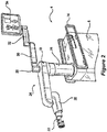
- Figures 3B and 3C illustrate a front view and isometric view of another camera tracking system component 6' which may be used with the surgical system of Figure 1 or may be used independent of a surgical robot.
- the camera tracking system component 6' may be used for providing navigated surgery without use of robotic guidance.
- One of the differences between the camera tracking system component 6' of Figures 3B and 3C and the camera tracking system component 6 of Figure 3A is that the camera tracking system component 6' of Figures 3B and 3C includes a housing that transports the computer platform 910.
- the computer platform 910 can be configured to perform camera tracking operations to track DRAs, perform navigated surgery operations that provide surgical navigation information to a display device, e.g., XR headset and/or other display device, and perform other computational operations disclosed herein.
- the computer platform 910 can therefore include a navigation computer, such as one or more of the navigation computers of Figures 14 .
- Figure 6 illustrates a block diagram view of the components of the surgical system of Figure 5 used for the medical operation.
- the tracking cameras 46 on the auxiliary tracking bar has a navigation field-of-view 600 in which the pose (e.g., position and orientation) of the reference array 602 attached to the patient, the reference array 604 attached to the surgical instrument, and the robot arm 20 are tracked.
- the tracking cameras 46 may be part of the camera tracking system component 6' of Figures 3B and 3C , which includes the computer platform 910 configured to perform the operations described below.
- the reference arrays enable tracking by reflecting light in known patterns, which are decoded to determine their respective poses by the tracking subsystem of the surgical robot 4.
- a responsive notification may temporarily halt further movement of the robot arm 20 and surgical robot 4, display a warning on the display 34, and/or provide an audible warning to medical personnel.
- the display 34 is accessible to the surgeon 610 and assistant 612 but viewing requires a head to be turned away from the patient and for eye focus to be changed to a different distance and location.
- the navigation software may be controlled by a tech personnel 614 based on vocal instructions from the surgeon.
- Figure 7 illustrates various display screens that may be displayed on the display 34 of Figures 5 and 6 by the surgical robot 4 when using a navigation function of the surgical system 2.
- the display screens can include, without limitation, patient radiographs with overlaid graphical representations of models of instruments that are positioned in the display screens relative to the anatomical structure based on a developed surgical plan and/or based on poses of tracked reference arrays, various user selectable menus for controlling different stages of the surgical procedure and dimension parameters of a virtually projected implant (e.g. length, width, and/or diameter).
- processing components e.g., computer platform 910 and associated software described below are provided that enable pre-operatively planning of a surgical procedure, e.g., implant placement, and electronic transfer of the plan to computer platform 910 to provide navigation information to one or more users during the planned surgical procedure.
- a surgical procedure e.g., implant placement
- electronic transfer of the plan to computer platform 910 to provide navigation information to one or more users during the planned surgical procedure.
- various processing components e.g., computer platform 910 and associated software described below are provided that enable pre-operatively planning of a surgical procedure, e.g., implant placement, and electronic transfer of the plan to the surgical robot 4.
- the surgical robot 4 uses the plan to guide the robot arm 20 and connected end effector 26 to provide a target pose for a surgical tool relative to a patient anatomical structure for a step of the planned surgical procedure.
- Various embodiments below are directed to using one or more XR headsets that can be worn by the surgeon 610, the assistant 612, and/or other medical personnel to provide an improved user interface for receiving information from and/or providing control commands to the surgical robot, the camera tracking system component 6/6', and/or other medical equipment in the operating room.
- FIG. 8 illustrates a block diagram of some electrical components of the surgical robot 4 according to some embodiments of the present disclosure.
- a load cell (not shown) may be configured to track force applied to end effector coupler 22.
- the load cell may communicate with a plurality of motors 850, 851, 852, 853, and/or 854.
- Controller 846 may take the force information from load cell and process it with a switch algorithm. The switch algorithm is used by the controller 846 to control a motor driver 842.
- the motor driver 842 controls operation of one or more of the motors 850, 851, 852, 853, and 854.
- Motor driver 842 may direct a specific motor to produce, for example, an equal amount of force measured by load cell through the motor.
- the force produced may come from a plurality of motors, e.g., 850-854, as directed by controller 846.
- motor driver 842 may receive input from controller 846.
- Controller 846 may receive information from load cell as to the direction of force sensed by load cell. Controller 846 may process this information using a motion controller algorithm. The algorithm may be used to provide information to specific motor drivers 842. To replicate the direction of force, controller 846 may activate and/or deactivate certain motor drivers 842.
- Controller 846 may control one or more motors, e.g. one or more of 850-854, to induce motion of end effector 26 in the direction of force sensed by load cell.
- This force-controlled motion may allow an operator to move SCARA 24 and end effector 26 effortlessly and/or with very little resistance. Movement of end effector 26 can be performed to position end effector 26 in any suitable pose (i.e., location and angular orientation relative to defined three-dimensional (3D) orthogonal reference axes) for use by medical personnel.
- Activation assembly 60 may form of a bracelet that wraps around end effector coupler 22.
- the activation assembly 60 may be located on any part of SCARA 24, any part of end effector coupler 22, may be worn by medical personnel (and communicate wirelessly), and/or any combination thereof.
- Activation assembly 60 may comprise of a primary button and a secondary button.
- Depressing primary button may allow an operator to move SCARA 24 and end effector coupler 22.
- SCARA 24 and end effector coupler 22 may not move until an operator programs surgical robot 4 to move SCARA 24 and end effector coupler 22, or is moved using primary button.
- it may require the depression of at least two non-adjacent primary activation switches before SCARA 24 and end effector coupler 22 will respond to operator commands. Depression of at least two primary activation switches may prevent the accidental movement of SCARA 24 and end effector coupler 22 during a medical procedure.
- load cell may measure the force magnitude and/or direction exerted upon end effector coupler 22 by an operator, i.e. medical personnel. This information may be transferred to one or more motors, e.g. one or more of 850-854, within SCARA 24 that may be used to move SCARA 24 and end effector coupler 22. Information as to the magnitude and direction of force measured by load cell may cause the one or more motors, e.g. one or more of 850-854, to move SCARA 24 and end effector coupler 22 in the same direction as sensed by the load cell.
- motors e.g. one or more of 850-854
- This force-controlled movement may allow the operator to move SCARA 24 and end effector coupler 22 easily and without large amounts of exertion due to the motors moving SCARA 24 and end effector coupler 22 at the same time the operator is moving SCARA 24 and end effector coupler 22.
- a secondary button may be used by an operator as a "selection" device.
- surgical robot 4 may notify medical personnel to certain conditions by the XR headset(s) 920, display 34 and/or light indicator 28.
- the XR headset(s) 920 are each configured to display images on a see-through display screen to form an extended reality image that is overlaid on real-world objects viewable through the see-through display screen.
- Medical personnel may be prompted by surgical robot 4 to select a function, mode, and/or asses the condition of surgical system 2.
- Depressing secondary button a single time may activate certain functions, modes, and/or acknowledge information communicated to medical personnel through the XR headset(s) 920, display 34 and/or light indicator 28.
- depressing the secondary button multiple times in rapid succession may activate additional functions, modes, and/or select information communicated to medical personnel through the XR headset(s) 920, display 34 and/or light indicator 28.
- electrical components of the surgical robot 4 include platform subsystem 802, computer subsystem 820, motion control subsystem 840, and tracking subsystem 830.
- Platform subsystem 802 includes battery 806, power distribution module 804, connector panel 808, and charging station 810.
- Computer subsystem 820 includes computer 822, display 824, and speaker 826.
- Motion control subsystem 840 includes driver circuit 842, motors 850, 851, 852, 853, 854, stabilizers 855, 856, 857, 858, end effector connector 844, and controller 846.
- Tracking subsystem 830 includes position sensor 832 and camera converter 834.
- Surgical robot 4 may also include a removable foot pedal 880 and removable tablet computer 890.
- Input power is supplied to surgical robot 4 via a power source which may be provided to power distribution module 804.
- Power distribution module 804 receives input power and is configured to generate different power supply voltages that are provided to other modules, components, and subsystems of surgical robot 4.
- Power distribution module 804 may be configured to provide different voltage supplies to connector panel 808, which may be provided to other components such as computer 822, display 824, speaker 826, driver 842 to, for example, power motors 850-854 and end effector coupler 844, and provided to camera converter 834 and other components for surgical robot 4.
- Power distribution module 804 may also be connected to battery 806, which serves as temporary power source in the event that power distribution module 804 does not receive power from an input power. At other times, power distribution module 804 may serve to charge battery 806.
- Connector panel 808 may serve to connect different devices and components to surgical robot 4 and/or associated components and modules.
- Connector panel 808 may contain one or more ports that receive lines or connections from different components.
- connector panel 808 may have a ground terminal port that may ground surgical robot 4 to other equipment, a port to connect foot pedal 880, a port to connect to tracking subsystem 830, which may include position sensor 832, camera converter 834, and camera tracking bar 870.
- Connector panel 808 may also include other ports to allow USB, Ethernet, HDMI communications to other components, such as computer 822.
- the connector panel 808 can include a wired and/or wireless interface for operatively connecting one or more XR headsets 920 to the tracking subsystem 830 and/or the computer subsystem 820.
- Control panel 816 may provide various buttons or indicators that control operation of surgical robot 4 and/or provide information from surgical robot 4 for observation by an operator.
- control panel 816 may include buttons to power on or off surgical robot 4, lift or lower vertical column 16, and lift or lower stabilizers 855-858 that may be designed to engage casters 12 to lock surgical robot 4 from physically moving.
- Other buttons may stop surgical robot 4 in the event of an emergency, which may remove all motor power and apply mechanical brakes to stop all motion from occurring.
- Control panel 816 may also have indicators notifying the operator of certain system conditions such as a line power indicator or status of charge for battery 806.
- one or more XR headsets 920 may communicate, e.g. via the connector panel 808, to control operation of the surgical robot 4 and/or to received and display information generated by surgical robot 4 for observation by persons wearing the XR headsets 920.
- Computer 822 of computer subsystem 820 includes an operating system and software to operate assigned functions of surgical robot 4.
- Computer 822 may receive and process information from other components (for example, tracking subsystem 830, platform subsystem 802, and/or motion control subsystem 840) in order to display information to the operator.
- computer subsystem 820 may provide output through the speaker 826 for the operator.
- the speaker may be part of the surgical robot, part of an XR headset 920, or within another component of the surgical system 2.
- the display 824 may correspond to the display 34 shown in Figures 1 and 2 .
- Tracking subsystem 830 may include position sensor 832 and camera converter 834. Tracking subsystem 830 may correspond to the camera tracking system component 6 of Figure 3 .
- the camera tracking bar 870 operate with the position sensor 832 to determine the pose of DRAs 52. This tracking may be conducted in a manner consistent with the present disclosure including the use of infrared or visible light technology that tracks the location of active or passive elements of DRAs 52, such as LEDs or reflective fiducials (also called markers), respectively.
- the tracking subsystem 830 and the computer subsystem 820 can be included in the computer platform 910, which can be transported by the camera tracking system component 6' of Figures 3A and 3B .
- the tracking subsystem 830 can be configured to determine the poses, e.g., location and angular orientation of the tracked DRAs.
- the computer platform 910 can also include a navigation controller that is configured to use the determined poses to provide navigation information to users that guides their movement of tracked tools relative to position-registered patient images and/or tracked anatomical structures during a planned surgical procedure.
- the computer platform 910 can display information on the display of Figures 3B and 3C and/or to one or more XR headsets 920.
- the computer platform 910 when used with a surgical robot, can be configured to communicate with the computer subsystem 820 and other subsystems of Figure 8 to control movement of the end effector 26.
- the computer platform 910 can generate a graphical representation of a patient's anatomical structure, surgical tool, user's hand, etc. with a displayed size, shape, color, and/or pose that is controlled based on the determined pose(s) of one or more the tracked DRAs, and which the graphical representation that is displayed can be dynamically modified to track changes in the determined poses over time.
- Motion control subsystem 840 may be configured to physically move vertical column 16, upper arm 18, lower arm 20, or rotate end effector coupler 22.
- the physical movement may be conducted through the use of one or more motors 850-854.
- motor 850 may be configured to vertically lift or lower vertical column 16.
- Motor 851 may be configured to laterally move upper arm 18 around a point of engagement with vertical column 16 as shown in Figure 2 .
- Motor 852 may be configured to laterally move lower arm 20 around a point of engagement with upper arm 18 as shown in Figure 2 .
- Motors 853 and 854 may be configured to move end effector coupler 22 to provide translational movement and rotation along in about three-dimensional axes.
- the computer platform 910 shown in Figure 9 can provide control input to the controller 846 that guides movement of the end effector coupler 22 to position a passive end effector, which is connected thereto, with a planned pose (i.e., location and angular orientation relative to defined 3D orthogonal reference axes) relative to an anatomical structure that is to be operated on during a planned surgical procedure.
- Motion control subsystem 840 may be configured to measure position of the end effector coupler 22 and/or the end effector 26 using integrated position sensors (e.g. encoders).
- Figure 9 illustrates a block diagram of components of a surgical system that includes imaging devices (e.g., C-Arm 104, O-Arm 106, etc.) connected to a computer platform 910 which can be operationally connected to a camera tracking system component 6 ( Fig. 3A ) or 6' ( Figs. 3B,3C ) and/or to surgical robot 4 according to some embodiments of the present disclosure.
- imaging devices e.g., C-Arm 104, O-Arm 106, etc.
- a computer platform 910 which can be operationally connected to a camera tracking system component 6 ( Fig. 3A ) or 6' ( Figs. 3B,3C ) and/or to surgical robot 4 according to some embodiments of the present disclosure.
- a camera tracking system component 6 Fig. 3A
- 6' Figs. 3B,3C
- the computer platform 910 includes a display 912, at least one processor circuit 914 (also referred to as a processor for brevity), at least one memory circuit 916 (also referred to as a memory for brevity) containing computer readable program code 918, and at least one network interface 902 (also referred to as a network interface for brevity).
- the display 912 may be part of an XR headset 920 in accordance with some embodiments of the present disclosure.
- the network interface 902 can be configured to connect to a C-Arm imaging device 104 in Figure 10 , an O-Arm imaging device 106 in Figure 11 , another medical imaging device, an image database 950 containing patient medical images, components of the surgical robot 4, and/or other electronic equipment.
- the display 912 When used with a surgical robot 4, the display 912 may correspond to the display 34 of Figure 2 and/or the tablet 890 of Figure 8 and/or the XR headset 920 that is operatively connected to the surgical robot 4, the network interface 902 may correspond to the platform network interface 812 of Figure 8 , and the processor 914 may correspond to the computer 822 of Figure 8 .
- the network interface 902 of the XR headset 920 may be configured to communicate through a wired network, e.g., thin wire ethernet, and/or through wireless RF transceiver link according to one or more wireless communication protocols, e.g., WLAN, 3GPP 4G and/or 5G (New Radio) cellular communication standards, etc.
- wireless communication protocols e.g., WLAN, 3GPP 4G and/or 5G (New Radio) cellular communication standards, etc.
- the processor 914 may include one or more data processing circuits, such as a general purpose and/or special purpose processor, e.g., microprocessor and/or digital signal processor.
- the processor 914 is configured to execute the computer readable program code 918 in the memory 916 to perform operations, which may include some or all of the operations described herein as being performed for surgery planning, navigated surgery, and/or robotic surgery.
- the computer platform 910 can be configured to provide surgery planning functionality.
- the processor 914 can operate to display on the display device 912 and/or on the XR headset 920 an image of an anatomical structure, e.g., vertebra, that is received from one of the imaging devices 104 and 106 and/or from the image database 950 through the network interface 920.
- the processor 914 receives an operator's definition of where the anatomical structure shown in one or more images is to have a surgical procedure, e.g., screw placement, such as by the operator touch selecting locations on the display 912 for planned procedures or using a mouse-based cursor to define locations for planned procedures.
- the XR headset can be configured to sense in gesture-based commands formed by the wearer and/or sense voice based commands spoken by the wearer, which can be used to control selection among menu items and/or control how objects are displayed on the XR headset 920 as will be explained in further detail below.
- the computer platform 910 can be configured to enable anatomy measurement, which can be particularly useful for knee surgery, like measurement of various angles determining center of hip, center of angles, natural landmarks (e.g. transepicondylar line, Whitesides line, posterior condylar line), etc. Some measurements can be automatic while some others can involve human input or assistance.
- the computer platform 910 may be configured to allow an operator to input a choice of the correct implant for a patient, including choice of size and alignment.
- the computer platform 910 may be configured to perform automatic or semi-automatic (involving human input) segmentation (image processing) for CT images or other medical images.
- the surgical plan for a patient may be stored in a cloud-based server, which may correspond to database 950, for retrieval by the surgical robot 4.
- a surgeon may choose which cut to make (e.g. posterior femur, proximal tibia etc.) using a computer screen (e.g. touchscreen) or extended reality (XR) interaction (e.g., hand gesture based commands and/or voice based commands) via, e.g., the XR headset 920.
- the computer platform 910 can generate navigation information which provides visual guidance to the surgeon for performing the surgical procedure.
- the computer platform 910 can provide guidance that allows the surgical robot 4 to automatically move the end effector 26 to a target pose so that the surgical tool is aligned with a target location to perform the surgical procedure on an anatomical structure.
- the surgical system 900 can use two DRAs to track patient anatomy position, such as one connected to patient tibia and one connected to patient femur.
- the system 900 may use standard navigated instruments for the registration and checks (e.g. a pointer similar to the one used in Globus ExcelsiusGPS system for spine surgery).
- a particularly challenging task in navigated surgery is how to plan the position of an implant in spine, knee, and other anatomical structures where surgeons struggle to perform the task on a computer screen which is a 2D representation of the 3D anatomical structure.
- the system 900 could address this problem by using the XR headset 920 to display a three-dimensional (3D) computer generated representations of the anatomical structure and a candidate implant device.
- the computer generated representations are scaled and posed relative to each other on the display screen under guidance of the computer platform 910 and which can be manipulated by a surgeon while viewed through the XR headset 920.
- a surgeon may, for example, manipulate the displayed computer-generated representations of the anatomical structure, the implant, a surgical tool, etc., using hand gesture based commands and/or voice based commands that are sensed by the XR headset 920.
- a surgeon can view a displayed virtual handle on a virtual implant, and can manipulate (e.g., grab and move) the virtual handle to move the virtual implant to a desired pose and adjust a planned implant placement relative to a graphical representation of an anatomical structure.
- the computer platform 910 could display navigation information through the XR headset 920 that facilitates the surgeon's ability to more accurately follow the surgical plan to insert the implant and/or to perform another surgical procedure on the anatomical structure.
- the progress of bone removal e.g., depth of cut
- Other features that may be displayed through the XR headset 920 can include, without limitation, gap or ligament balance along a range of joint motion, contact line on the implant along the range of joint motion, ligament tension and/or laxity through color or other graphical renderings, etc.
- the computer platform 910 can allow planning for use of standard surgical tools and/or implants, e.g., posterior stabilized implants and cruciate retaining implants, cemented and cementless implants, revision systems for surgeries related to, for example, total or partial knee and/or hip replacement and/or trauma.
- standard surgical tools and/or implants e.g., posterior stabilized implants and cruciate retaining implants, cemented and cementless implants, revision systems for surgeries related to, for example, total or partial knee and/or hip replacement and/or trauma.
- An automated imaging system can be used in conjunction with the computer platform 910 to acquire pre-operative, intra-operative, post-operative, and/or real-time image data of an anatomical structure.
- Example automated imaging systems are illustrated in Figures 10 and 11 .
- the automated imaging system is a C-arm 104 ( Fig. 10 ) imaging device or an O-arm ® 106 ( Fig. 11 ).
- O-arm ® is copyrighted by Medtronic Navigation, Inc. having a place of business in Louisville, Colo., USA). It may be desirable to take x-rays of a patient from a number of different positions, without the need for frequent manual repositioning of the patient which may be required in an x-ray system.
- C-arm 104 x-ray diagnostic equipment may solve the problems of frequent manual repositioning and may be well known in the medical art of surgical and other interventional procedures.
- a C-arm includes an elongated C-shaped member terminating in opposing distal ends 112 of the "C" shape.
- C-shaped member is attached to an x-ray source 114 and an image receptor 116.
- the space within C-arm 104 of the arm provides room for the physician to attend to the patient substantially free of interference from the x-ray support structure.
- the C-arm is mounted to enable rotational movement of the arm in two degrees of freedom, (i.e. about two perpendicular axes in a spherical motion).
- C-arm is slidably mounted to an x-ray support structure, which allows orbiting rotational movement of the C-arm about its center of curvature, which may permit selective orientation of x-ray source 114 and image receptor 116 vertically and/or horizontally.
- the C-arm may also be laterally rotatable, (i.e. in a perpendicular direction relative to the orbiting direction to enable selectively adjustable positioning of x-ray source 114 and image receptor 116 relative to both the width and length of the patient).
- Spherically rotational aspects of the C-arm apparatus allow physicians to take x-rays of the patient at an optimal angle as determined with respect to the particular anatomical condition being imaged.
- the O-arm ® 106 illustrated in Figure 11 includes a gantry housing 124 which may enclose an image capturing portion, not illustrated.
- the image capturing portion includes an x-ray source and/or emission portion and an x-ray receiving and/or image receiving portion, which may be disposed about one hundred and eighty degrees from each other and mounted on a rotor (not illustrated) relative to a track of the image capturing portion.
- the image capturing portion may be operable to rotate three hundred and sixty degrees during image acquisition.
- the image capturing portion may rotate around a central point and/or axis, allowing image data of the patient to be acquired from multiple directions or in multiple planes.
- the O-arm ® 106 with the gantry housing 124 has a central opening for positioning around an object to be imaged, a source of radiation that is rotatable around the interior of gantry housing 124, which may be adapted to project radiation from a plurality of different projection angles.
- a detector system is adapted to detect the radiation at each projection angle to acquire object images from multiple projection planes in a quasi-simultaneous manner.
- the gantry may be attached to a support structure O-arm ® support structure, such as a wheeled mobile cart with wheels, in a cantilevered fashion.
- a positioning unit translates and/or tilts the gantry to a planned position and orientation, preferably under control of a computerized motion control system.
- the gantry may include a source and detector disposed opposite one another on the gantry.
- the source and detector may be secured to a motorized rotor, which may rotate the source and detector around the interior of the gantry in coordination with one another.
- the source may be pulsed at multiple positions and orientations over a partial and/or full three hundred and sixty degree rotation for multi-planar imaging of a targeted object located inside the gantry.
- the gantry may further comprise a rail and bearing system for guiding the rotor as it rotates, which may carry the source and detector.
- Both and/or either O-arm ® 106 and C-arm 104 may be used as automated imaging system to scan a patient and send information to the surgical system 2.
- Images captured by an imaging system can be displayed on the XR headset 920 and/or another display device of the computer platform 910, the surgical robot 4, and/or another component of the surgical system 900.
- the XR headset 920 may be connected to one or more of the imaging devices 104 and/or 106 and/or to the image database 950, e.g., via the computer platform 910, to display images therefrom.
- a user may provide control inputs through the XR headset 920, e.g., gesture and/or voice based commands, to control operation of one or more of the imaging devices 104 and/or 106 and/or the image database 950.
- Figure 12 illustrates a block diagram view of the components of a surgical system that include a pair of XR headsets 920 (head-mounted displays HMD1 and HMD2), which may correspond to the XR headset 920 shown in Figure 13 and operate in accordance with some embodiments of the present disclosure.
- XR headsets 920 head-mounted displays HMD1 and HMD2
- the assistant 612 and surgeon 610 are both wearing the XR headsets 920, respectively. It is optional for the assistant 612 to wear the XR headset 920.
- the XR headsets 920 are configured to provide an interactive environment through which the wearers can view and interact with information related to a surgical procedure as will be described further below. This interactive XR based environment may eliminate a need for the tech personnel 614 shown in Figure 6 to be present in the operating room and may eliminate a need for use of the display 34 shown in Figure 6 .
- Each XR headset 920 can include one or more cameras that are configured to provide an additional source of tracking of DRAs or other reference arrays attached to surgical tools, a patient's anatomical structure, the end effector 26, and/or other equipment.
- XR headset 920 has a field-of-view (FOV) 1202 for tracking DRAs and other objects
- XR headset 920 has a FOV 1212 partially overlapping FOV 1202 for tracking DRAs and other objects
- the tracking cameras 46 has another FOV 600 partially overlapping FOVs 1202 and 1212 for tracking DRAs and other objects.
- FOV field-of-view
- the tracking subsystem 830 and/or navigation controller 828 can continue to track the object seamlessly without loss of navigation. Additionally, if there is partial occlusion of the DRA from the perspective of one camera, but the entire DRA is visible via multiple camera sources, the tracking inputs of the cameras can be merged to continue navigation of the DRA.
- One of the XR headsets and/or the tracking cameras 46 may view and track the DRA on another one of the XR headsets to enable the computer platform 910 ( Figs.
- the tracking subsystem 830 and/or another computing component to determine the pose of the DRA relative to one or more defined coordinate systems, e.g., of the XR headsets 920, the tracking cameras 46, and/or another coordinate system defined for the patient, table, and/or room.
- one or more defined coordinate systems e.g., of the XR headsets 920, the tracking cameras 46, and/or another coordinate system defined for the patient, table, and/or room.
- the XR headsets 920 can be operatively connected to view video, pictures, and/or other received information and/or to provide commands that control various equipment in the surgical room, including but not limited to neuromonitoring, microscopes, video cameras, and anesthesia systems. Data from the various equipment may be processed and displayed within the headset, for example the display of patient vitals or the microscope feed.
- FIG. 13 illustrates an XR headset 920 which is configured in accordance with some embodiments of the present disclosure.
- the XR headset includes a headband 1306 configured to secure the XR headset to a wearer's head, an electronic component enclosure 1304 supported by the headband 1306, and a display screen 1302 that extends laterally across and downward from the electronic component enclosure 1304.
- the display screen 1302 may be a see-through LCD display device or a semi-reflective lens that reflects images projected by a display device toward the wearer's eyes.
- a set of DRA fiducials 1310 e.g., dots, are painted or attached in a spaced apart known arranged on one or both sides of the headset.
- the DRA on the headset enables the tracking cameras on the auxiliary tracking bar to track pose of the headset 920 and/or enables another XR headset to track pose of the headset 920.
- the display screen 1302 operates as a see-through display screen, also referred to as a combiner, that reflects light from display panels of a display device toward the user's eyes.
- the display panels can be located between the electronic component enclosure and the user's head, and angled to project virtual content toward the display screen 1302 for reflection toward the user's eyes.
- the display screen 1302 is semi-transparent and semi-reflective allowing the user to see reflected virtual content superimposed on the user's view of a real-world scene.
- the display screen 1302 may have different opacity regions, such as the illustrated upper laterally band which has a higher opacity than the lower laterally band.
- Opacity of the display screen 1302 may be electronically controlled to regulate how much light from the real-world scene passes through to the user's eyes.
- a high opacity configuration of the display screen 1302 results in high-contrast virtual images overlaid on a dim view of the real-world scene.
- a low opacity configuration of the display screen 1302 can result in more faint virtual images overlaid on a clearer view of the real-world scene.
- the opacity may be controlled by applying an opaque material on a surface of the display screen 1302.
- the surgical system includes an XR headset 920 and an XR headset controller, e.g., controller 1430 in Fig. 14 .
- the XR headset 920 is configured to be worn by a user during a surgical procedure and has a see-through display screen 1302 that is configured to display an XR image and to allow at least a portion of a real-world scene to pass therethrough for viewing by the user.
- the XR headset 920 also includes an opacity filter positioned between at least one of the user's eyes and the real-world scene when the see-through display screen 1302 is viewed by the user.
- the opacity filter is configured to provide opaqueness to light from the real-world scene.
- the XR headset controller is configured to communicate with a navigation controller, e.g., controller(s) 828A, 828B, and/or 828C in Fig. 14 , to receive navigation information from the navigation controller which provides guidance to the user during the surgical procedure on an anatomical structure, and is further configured to generate the XR image based on the navigation information for display on the see-through display screen 1302.
- a navigation controller e.g., controller(s) 828A, 828B, and/or 828C in Fig. 14
- the XR headset controller is configured to communicate with a navigation controller, e.g., controller(s) 828A, 828B, and/or 828C in Fig. 14 , to receive navigation information from the navigation controller which provides guidance to the user during the surgical procedure on an anatomical structure, and is further configured to generate the XR image based on the navigation information for display on the see-through display screen 1302.
- Opacity of the display screen 1302 may be configured as a gradient having a more continuously changing opacity with distance downward from a top portion of the display screen 1302.
- the gradient's darkest point can be located at the top portion of the display screen 1302, and gradually becoming less opaque further down on the display screen 1302 until the opacity is transparent or not present.
- the gradient can change from about 90% opacity to entirely transparent approximately at the mid-eye level of the display screen 1302. With the headset properly calibrated and positioned, the mid-eye level can correspond to the point where the user would look straight out, and the end of the gradient would be located at the "horizon" line of the eye. The darker portion of the gradient will allow crisp, clear visuals of the virtual content and help to block the intrusive brightness of the overhead operating room lights.
- an opacity filter in this manner enables the XR headset 920 to provide virtual reality (VR) capabilities, by substantially or entirely blocking light from the real-world scene, along an upper portion of the display screen 1302 and to provide AR capabilities along a middle or lower portion of the display screen 1302. This allows the user to have the semi-translucence of AR where needed and allowing clear optics of the patient anatomy during procedures.
- Configuring the display screen 1302 as a gradient instead of as a more constant opacity band can enable the wearer to experience a more natural transition between a more VR type view to a more AR type view without experiencing abrupt changes in brightness of the real-world scene and depth of view that may otherwise strain the eyes such as during more rapid shifting between upward and downward views.
- the display panels and display screen 1302 can be configured to provide a wide field of view see-through XR display system. In one example configuration they provide an 80° diagonal field-of-view (FOV) with 55° of vertical coverage for a user to view virtual content. Other diagonal FOV angles and vertical coverage angles can be provided through different size display panels, different curvature lens, and/or different distances and angular orientations between the display panels and curved display screen 1302.
- FOV field-of-view
- Figure 14 illustrates electrical components of the XR headset 920 that can be operatively connected to the computer platform 910, to one or more of the imaging devices, such as the C-arm imaging device 104, the O-arm imaging device 106, and/or the image database 950, and/or to the surgical robot 800 in accordance with various embodiments of the present disclosure.
- the imaging devices such as the C-arm imaging device 104, the O-arm imaging device 106, and/or the image database 950, and/or to the surgical robot 800 in accordance with various embodiments of the present disclosure.
- the XR headset 920 provides an improved human interface for performing navigated surgical procedures.
- the XR headset 920 can be configured to provide functionalities, e.g., via the computer platform 910, that include without limitation any one or more of: identification of hand gesture based commands and/or voice based commands, display XR graphical objects on a display device 1450.
- the display device 1450 may be a video projector, flat panel display, etc., which projects the displayed XR graphical objects onto the display screen 1302.
- the user can view the XR graphical objects as an overlay anchored to particular real-world objects viewed through the display screen 1302 ( Fig. 13 ).
- the XR headset 920 may additionally or alternatively be configured to display on the display screen 1450 video feeds from cameras mounted to one or more XR headsets 920 and other cameras.
- Electrical components of the XR headset 920 can include a plurality of cameras 1440, a microphone 1442, a gesture sensor 1444, a pose sensor (e.g., inertial measurement unit (IMU)) 1446, a display module 1448 containing the display device 1450, and a wireless/wired communication interface 1452.
- the cameras 1440 of the XR headset may be visible light capturing cameras, near infrared capturing cameras, or a combination of both.
- the cameras 1440 may be configured operate as the gesture sensor 1444 by capturing for identification user hand gestures performed within the field of view of the camera(s) 1440.
- the gesture sensor 1444 may be a proximity sensor and/or a touch sensor that senses hand gestures performed proximately to the gesture sensor 1444 and/or senses physical contact, e.g. tapping on the sensor or the enclosure 1304.
- the pose sensor 1446 e.g., IMU, may include a multi-axis accelerometer, a tilt sensor, and/or another sensor that can sense rotation and/or acceleration of the XR headset 920 along one or more defined coordinate axes. Some or all of these electrical components may be contained in the component enclosure 1304 or may be contained in another enclosure configured to be worn elsewhere, such as on the hip or shoulder.
- the surgical system 2 includes a camera tracking system component 6/6' and a tracking subsystem 830 which may be part of the computer platform 910.
- the surgical system may include imaging devices (e.g., C-arm 104, O-arm 106, and/or image database 950) and/or a surgical robot 4.
- the tracking subsystem 830 is configured to determine a pose of DRAs attached to an anatomical structure, an end effector, a surgical tool, etc.
- a navigation controller 828 is configured to determine a target pose for the surgical tool relative to an anatomical structure based on a surgical plan, e.g., from a surgical planning function performed by the computer platform 910 of Fig.
- the navigation controller 828 may be further configured to generate steering information based on the target pose for the surgical tool, the pose of the anatomical structure, and the pose of the surgical tool and/or the end effector, where the steering information indicates where the surgical tool and/or the end effector of a surgical robot should be moved to perform the surgical plan.
- Various of the cameras 1440 of the XR headset 920 may be connected to the camera tracking system component 6/6' to track poses of DRAs, user's hand(s), etc.
- the electrical components of the XR headset 920 can be operatively connected to the electrical components of the computer platform 910 through a wired/wireless interface 1452.
- the electrical components of the XR headset 920 may be operatively connected, e.g., through the computer platform 910 or directly connected, to various imaging devices, e.g., the C-arm imaging device 104, the I/O-arm imaging device 106, the image database 950, and/or to other medical equipment through the wired/wireless interface 1452.
- the surgical system 2 further includes at least one XR headset controller 1430 (also referred to as "XR headset controller” for brevity) that may reside in the XR headset 920, the computer platform 910, and/or in another system component connected via wired cables and/or wireless communication links.
- XR headset controller 1430 is configured to receive navigation information from the navigation controller 828 which provides guidance to the user during the surgical procedure on an anatomical structure, and is configured to generate an XR image based on the navigation information for display on the display device 1450 for projection on the see-through display screen 1302.
- the configuration of the display device 1450 relative to the display screen (also referred to as "see-through display screen ”) 1302 is configured to display XR images in a manner such that when the user wearing the XR headset 920 looks through the display screen 1302 the XR images appear to be in the real world.
- the display screen 1302 can be positioned by the headband 1306 in front of the user's eyes.
- the XR headset controller 1430 can be within a housing that is configured to be worn on a user's head or elsewhere on the user's body while viewing the display screen 1302 or may be remotely located from the user viewing the display screen 1302 while being communicatively connected to the display screen 1302.
- the XR headset controller 1430 can be configured to operationally process signaling from the cameras 1440, the microphone 142, and/or the pose sensor 1446, and is connected to display XR images on the display device 1450 for user viewing on the display screen 1302.
- the XR headset controller 1430 illustrated as a circuit block within the XR headset 920 is to be understood as being operationally connected to other illustrated components of the XR headset 920 but not necessarily residing within a common housing (e.g., the electronic component enclosure 1304 of Fig. 13 ) or being otherwise transportable by the user.
- the XR headset controller 1430 may reside within the computer platform 910 which, in turn, may reside within a housing of the computer tracking system component 6' shown in Figures 3B and 3C .
- Figure 15 illustrates a block diagram showing arrange of optical components of the XR headset 920 in accordance with some embodiments of the present disclosure.
- the display device 1450 is configured to display XR images generated by the XR headset controller 1430, light from which is projected as XR images 1500 toward the display screen 1302.
- the display screen 1302 is configured to combine light of the XR images 1500 and light from the real-world scene 1502 into a combined augmented view 1504 that is directed to the user's eye(s) 1510.
- the display screen 1302 configured in this manner operates as a see-through display screen.
- the XR headset 920 can include any plural number of tracking cameras 1440.
- the cameras 1440 may be visible light capturing cameras, near infrared capturing cameras, or a combination of both.
- the XR headset operations can display both 2D images and 3D models on the display screen 1302.
- the 2D images may preferably be displayed in a more opaque band of the display screen 1302 (upper band) and the 3D model may be more preferably displayed in the more transparent band of the display screen 1302, otherwise known as the environmental region (bottom band). Below the lower band where the display screen 1302 ends the wearer has an unobstructed view of the surgical room.
- XR content is display on the display screen 1302 may be fluidic. It is possible that where the 3D content is displayed moves to the opaque band depending on the position of the headset relative to the content, and where 2D content is displayed can be placed in the transparent band and stabilized to the real world.
- the entire display screen 1302 may be darkened under electronic control to convert the headset into virtual reality for surgical planning or completely transparent during the medical procedure.
- the XR headset 920 and associated operations not only support navigated procedures, but also can be performed in conjunction with robotically assisted procedures.
- Figure 16 illustrates an example view through the display screen 1302 of the XR headset 920 for providing navigation assistance to a user who is manipulating a surgical tool 1602 during a medical procedure in accordance with some embodiments of the present disclosure.
- a graphical representation 1600 of the tool can be displayed in 2D and/or 3D images in relation to a graphical representation 1610 of the anatomical structure.
- the user can use the viewed graphical representations to adjust a trajectory 1620 of the surgical tool 1602, which can be illustrated as extending from the graphical representation 2000 of the tool through the graphical representation 1610 of the anatomical structure.
- the XR headset 920 may also display textual information and other objects 1640.
- the dashed line 1650 extending across the viewed display screen represents an example division between different opacity level upper and lower bands.
- XR images virtual content
- Other types of XR images can include, but are not limited to any one or more of:
- Figure 17 illustrates example configuration of an auxiliary tracking bar 46 having two pairs of stereo tracking cameras configured in accordance with some embodiments of the present disclosure.
- the auxiliary tracking bar 46 is part of the camera tracking system component of Figures 3A , 3B, and 3C .
- the stereo tracking cameras include a stereo pair of spaced apart visible light capturing cameras and another stereo pair of spaced apart near infrared capturing cameras, in accordance with one embodiment.
- only one stereo pair of visible light capturing cameras or only one stereo pair of near infrared capture cameras can used in the auxiliary tracking bar 46. Any plural number of near infrared and/or visible light cameras can be used.
- navigated surgery can include computer vision tracking and determination of pose (e.g., position and orientation in a six degree-of-freedom coordinate system) of surgical instruments, such as by determining pose of attached DRAs that include spaced apart fiducials, e.g., disks or spheres, arranged in a manner known to the camera tracking system.
- the computer vision uses spaced apart tracking cameras, e.g., stereo cameras, that are configured to capture near infrared and/or visible light.
- Computer operations may combine (chain) measured poses in ways that can improve optimization of one or more of the above three parameters by incorporating additional tracking cameras mounted to one or more XR headsets.
- a stereo pair of visible light tracking cameras and another stereo pair of near infrared tracking cameras can be attached to the auxiliary tracking bar of the camera tracking system component in accordance with some embodiments of the present disclosure.
- Operational algorithms are disclosed that analyze the pose of DRAs that are fully observed or partially observed (e.g., when less than all of the fiducials of a DRA are viewed by a pair of stereo cameras), and combine the observed poses or partial poses in ways that can improve accuracy, robustness, and/or ergonomics during navigated surgery.
- the XR headset may be configured to augment a real-world scene with computer generated XR images.
- the XR headset may be configured to provide an XR viewing environment by displaying the computer generated XR images on a see-through display screen that allows light from the real-world scene to pass therethrough for combined viewing by the user.
- the XR headset may be configured to provide a VR viewing environment by preventing or substantially preventing light from the real-world scene from being directly viewed by the user along the viewing path of the displayed XR images.
- An XR headset can be configured to provide both AR and VR viewing environments.
- both AR and VR viewing environments are provided by lateral bands of substantially differing opacity arranged between the see-through display screen and the real-world scene, so that a VR viewing environment is provided for XR images aligned with a high opacity band and an AR viewing environment is provided for XR images aligned with the low opacity band.
- both AR and VR viewing environments are provided by computer adjustable control of an opacity filter that variably constrains how much light from the real-world scene passes through a see-through display screen for combining with the XR images viewed by the user.
- the XR headset can also be referred to as an AR headset or a VR headset.
- the XR headset can include near infrared tracking cameras and/or visible light tracking cameras that are configured to track fiducials of DRAs connected to surgical instruments, patient anatomy, other XR headset(s), and/or a robotic end effector.
- near infrared tracking and/or visible light tracking on the XR headset provides additional tracking volume coverage beyond what cameras on a single auxiliary tracking bar can provide. Adding near infrared tracking cameras to the existing auxiliary tracking bar allows for the headset location to be tracked more robustly but less accurately than in visible light.
- Mechanically calibrating the visible and near infrared tracking coordinate systems enables the coordinate systems to be aligned sufficiently to perform 3D DRA fiducials triangulation operations using stereo matching to jointly identify pose of the DRA fiducials between the visible and near infrared tracking coordinate systems.
- Using both visible and near infrared tracking coordinate systems can enable any one or more of: (a) identifying tools that would not be identified using a single coordinate system; (b) increased pose tracking accuracy; (c) enabling a wider range of motion without losing tracking of surgical instruments, patient anatomy, and/or a robotic end effector; and (d) naturally track an XR headset in the same coordinate system as the navigated surgical instruments.
- Figure 18 illustrates a block diagram view of the components of a surgical system that include tracking cameras in a pair of XR headsets 920 (head-mounted displays HMD1 and HMD2) and tracking cameras in a camera tracking bar in the camera tracking system component 6' which houses the computer platform 910.
- the computer platform 910 can include the tracking subsystem 830, the navigation controller 828, and the XR headset controller 1430 as was earlier shown in Figure 14 .
- a surgeon and an assistant are both wearing XR headsets HMD1 920 and HMD2 920, respectively, each if which includes tracking cameras that may be configured as shown in Figure 13 . It is optional for the assistant to wear the XR headset HMD2 920.
- the combination of XR headsets HMD1 920 and HMD2 920 and the tracking cameras 46 on the auxiliary tracking bar can, in operation with the computer platform 910, more robustly track the example objects of a patient reference array (R), robotic end effector (E), and surgical tool (T) or instrument.
- R patient reference array
- E robotic end effector
- T surgical tool
- the overlapping views from different perspectives that are provided by the XR headsets HMD1 920 and HMD2 920 and the tracking cameras 46 on the auxiliary tracking bar are shown in Figure 12 .
- T N 2 S is calibrated: T N 3 A ; T N V , where the term "T" is defined as a six degree-of-freedom (6 DOF) homogeneous transformation between the two indicated coordinates systems.
- T N 2 S is a 6 DOF homogeneous transformation between the visible light coordinate system of the primary headset HMD1 920 and the NIR coordinate system of the primary headset HMD1 920.
- the XR headsets HMD1 920 and HMD2 920 have passive visible light fiducials painted or otherwise attached to them (coordinate systems S and A), such as the reference array fiducials 1310 shown in Figure 13 .
- the tracking cameras are spatially calibrated to these passive fiducials (coordinate systems N2 and N3).
- the cameras on the XR headset HMD1 920 and HMD2 920 and the tracking cameras 46 on the auxiliary tracking bar have partially overlapping field of views. If one or more of the cameras on the XR headset HMD1 920 are obstructed from viewing a DRA attached to a tracked object, e.g., a tracked tool (T), but the DRA is in view of the cameras of the other XR headset HMD2 920 and/or the tracking cameras 46 on the auxiliary tracking bar, the computer platform 910 can continue to track the DRA seamlessly without loss of navigation.
- a tracked object e.g., a tracked tool (T)
- the tracking inputs of the cameras can be merged to continue navigation of the DRA.
- the various coordinate systems can be chained together by virtue of independent observations the various camera systems provided by the XR headsets HMD1 920 and HMD2 920 and the tracking cameras 46 on the auxiliary tracking bar.
- each of the XR headsets HMD1 920 and HMD2 920 may require virtual augmentation of the robotic end effector (E). While one XR headset HMD1 920 (N2) and the tracking cameras 46 on the auxiliary tracking bar (N) are able to see (E), perhaps the other XR headset HMD2 920 (N3) cannot.
- the location of (E) with respect to (N3) can still be computed via one of several different operational methods. Operations according to one embodiment performing chaining of poses from a patient reference (R).
- the chains can be arbitrarily long and are enabled by having more than one stereo camera system (e.g., N, N2, N3).
- the camera tracking system can be configured to receive tracking information related to tracked objects from a first tracking camera (e.g., N3) and a second tracking camera (e.g., N2) during a surgical procedure.
- the camera tracking system can determine a first pose transform (e.g., T N 3 R ) between a first object (e.g., R) coordinate system and the first tracking camera (e.g., N3) coordinate system based on first object tracking information from the first tracking camera (e.g., N3) which indicates pose of the first object (e.g., R).
- the camera tracking system can determine a second pose transform (e.g., T R N 2 ) between the first object (e.g., R) coordinate system and the second tracking camera (e.g., N2) coordinate system based on first object tracking information from the second tracking camera (e.g., N2) which indicates pose of the first object (e.g., R).
- the camera tracking system can determine a third pose transform (e.g., T N 2 E ) between a second object (e.g., E) coordinate system and the second tracking camera (e.g., N2) coordinate system based on second object tracking information from the second tracking camera (e.g., N2) which indicates pose of the second object (e.g., E).
- the camera tracking system can determine a fourth pose transform (e.g., T N 3 E ) between the second object (e.g., E) coordinate system and the first tracking camera (e.g., N3) coordinate system based on combining the first, second, and third pose transforms.
- a fourth pose transform e.g., T N 3 E
- the camera system can further determine pose of the second object (e.g., E) and the first tracking camera system (e.g., N3) coordinate system based on processing the tracking information through the fourth pose transform.
- the camera tracking system is capable of determining the pose of the second object (e.g., E) relative to first tracking camera (e.g., N3) when the first camera is blocked from seeing the second object (e.g., E).
- the camera tracking system is further configured to determine the fourth pose transform (e.g., T N 3 E ) between the second object (e.g., E) coordinate system and the first tracking camera (e.g., N3) coordinate system without use of any tracking information from the first tracking camera (e.g., N3) indicating pose of the second object (e.g., E).
- the camera tracking system may achieve higher tracking accuracy by merging synchronized imagery from multiple camera systems.
- the camera tracking system can determine pose of the second object (e.g., E) relative to first tracking camera (e.g., N3) by merging synchronized imagery of the second object (e.g., E) from multiple perspectives (first and second tracking cameras), and can use weighting which can be determined based on accuracy specs of the respective cameras.
- the camera tracking system can be further configured to determine the fourth pose transform (e.g., T N 3 E ) between the second object (e.g., E) coordinate system and the first tracking camera (e.g., N3) coordinate system based on second object tracking information from the first tracking camera (e.g., N3) which indicates pose of the second object (e.g., E) and further based on a result of the combining of the first, second, and third pose transforms.
- the fourth pose transform e.g., T N 3 E
- the first tracking camera e.g., N3 coordinate system
- the surgical system may be configured to display on the see-through display screen of an XR headset an XR image having a pose that is determined based on the fourth pose transform.
- the camera tracking system may be further configured to generate the XR image as a graphical representation of the second object (e.g., E) that is posed on the see-through display screen based on processing through the fourth pose transform the first object tracking information from the first and second tracking cameras and the second object tracking information from the second tracking camera.
- the camera tracking system can include a navigation controller 828 communicatively connected to the first tracking camera (e.g., N3) and the second tracking camera (e.g., N2) to receive the tracking information and configured to perform the determination of the first, second, third, and fourth pose transforms.
- a navigation controller 828 communicatively connected to the first tracking camera (e.g., N3) and the second tracking camera (e.g., N2) to receive the tracking information and configured to perform the determination of the first, second, third, and fourth pose transforms.
- a camera tracking bar which can include five cameras designed, configured, calibrated and used in such a way as to enable the camera tracking bar to provide improved tracking of objects for computer assisted navigation during surgery.
- the camera tracking bar uses ambient visible light for instrument, end effector and direct patient anatomy tracking in accordance with some embodiments.
- a near-infrared (NIR) illuminator circuit is also included with at least one of the five cameras capable of detecting the NIR illumination.
- the illumination can be helpful for tracking in dark environments or distinguishing retro-reflective surfaces from normal surfaces at very low image sensor exposures.
- the additional cameras (beyond just two stereo) increase the volume in which object tracking can be accomplished. This reduces the impact of a problem with current systems where small tracking volumes force surgical staff to frequently reposition the camera tracking bar and/or result in loss of object tracking and unexpectedly interruption of navigated surgery operations.
- Visible light tracking from ambient light can be difficult because of the high dynamic range required from the image sensors. To put it simply, there is a large difference in lighting between the center of a bright or spotlight and the surrounding area. Having multiple stereo pairs allows for optical marker detection and tracking at different exposures simultaneously. The inclusion of any more than two stereo cameras also removes point triangulation ambiguity, which effectively means that there is less "interference" present.
- Figure 19 illustrates some embodiments of the primary components of the disclosed camera tracking bar.
- a camera tracking bar includes a first set of stereo tracking cameras 1900, a second set of tracking cameras 1910, and a communication interface 1970, as illustrated in Figure 19 .
- the first set of stereo tracking cameras 1900 are the outermost stereo cameras.
- the resolution of the first set of stereo tracking cameras 1900, field of view of the lenses, baseline 1905 (separation between the first set of stereo tracking cameras), and mounting angle are all tuned for the application as each has an impact on accuracy, acuity and supported stereo tracking volume.
- a wider baseline allows for better triangulation and depth perception accuracy, but there is more error for farther away objects the farther apart the cameras are.
- the camera tracking bar also includes a second set of tracking cameras 1910 just inside of the original pair. These cameras can have a wider field of view and be angled inward in order to detect tracked objects outside of the normal tracking area.
- the resolution of the second set of stereo tracking cameras 1910, field of view of the lenses, baseline 1915 (separation between the first set of stereo tracking cameras), and mounting angle are all tuned for the application as each has an impact on accuracy, acuity and supported stereo tracking volume.
- the camera tracking bar of a camera tracking system for computer assisted navigation during surgery includes a first set of stereo tracking cameras 1900 having a first resolution, a first field of view, and spaced apart on the camera tracking bar by a first baseline distance 1905.
- the camera tracking bar also includes a second set of stereo tracking cameras 1910 having a second resolution, a second field of view, and spaced apart on the camera tracking bar by a second baseline distance 1915 that is less than the first baseline distance 1905.
- the second set of stereo tracking cameras 1910 is positioned between the first set of stereo tracking cameras 1900, and the resolution and/or the field of view of the second set of stereo tracking cameras 1910 is different from the resolution and/or the field of view of the first set of stereo tracking cameras 1900.
- the camera tracking bar also includes a communication interface 1970 configured to provide video streams from the first set of stereo tracking cameras 1900 and the second set of stereo tracking cameras 1910 to the camera tracking subsystem.
- each of the first set of stereo tracking cameras 1900 are attached to a surface of the camera tracking bar and angled inward toward each other at a first angle
- each of the second set of stereo tracking cameras 1910 are attached to a surface of the camera tracking bar and angled inward toward each other at a second angle that is different from the first angle.
- a color camera 1920 or a set of color cameras may be included for recording or training purposes.
- the color camera included here is well calibrated with the other four cameras so that color information can be added to tracked objects for improved recognition and differentiation between configurations of tracked objects.
- the camera tracking bar also may include a high rate inertial measurement unit (IMU) 1940.
- the IMU 1940 allows automatic differentiation between camera and tracked object motion.
- the IMU measures angular velocity and linear acceleration due to motion and gravity. Not only is this IMU used to differentiate between camera and tracked object motion, but it provides an accurate estimate of the camera and all tracked instruments to gravity.
- the IMU 1940 may include a 3-axis gyroscope and a 3-axis accelerometer.
- the IMU 1940 is configured to output motion data indicating measured motion of the camera tracking bar and the communication interface is further configured to provide the motion data to the camera tracking subsystem.
- the inertial measurement unit may be configured to include in the motion data measurements of an angular velocity of the 3-axis gyroscope and measurements of a linear acceleration of the 3-axis accelerometer.
- the camera tracking bar may further include a processor configured to align orientation of the video streams and the motion data measurements to a gravity reference.
- the camera tracking bar also may include a microphone array 1950 including a plurality of microphones spaced apart along the camera tracking bar and connected to provide at least one audio stream to a computer platform.
- the computer platform is configured to perform at least one of recording the at least one audio stream, identifying voice commands contained in the at least one audio stream and selectively trigger defined operations that are associated with identified ones of the voice commands, measuring ambient noise levels contained in the at least one audio stream, and triangulating location of a source of a sound contained in at least two audio streams provided by the plurality of microphones.
- the microphone array 1950 has been incorporated into to the tracking bar in order to record audio for training, triggering voice commands, measuring ambient noise levels and triangulating from where the sound came from.
- the microphone array 1950 can also be used to collect data for deep learning. Background conversation and equipment noise such as high-speed drills or saws can be measured, detected and timestamped relative to the entire situation.
- the camera tracking bar may be used to track disks or retro-reflective spheres on a dynamic reference array.
- the resolution, field of view, baseline distance, and mounting angle of the individual tracking cameras are all optimized for detecting the disks or retro-reflective spheres with an ideal pixel density, such as a pixel array of at least 10 pixels by 10 pixels and not more than 30 pixels by 30 pixels.
- the first resolution and the first field of view of the first set of stereo tracking cameras 1900 are configured to output frames in the video stream imaging a reference array posed during surgery extends across a pixel array of at least 10 pixels by 10 pixels and not more than 30 pixels by 30 pixels.
- the second resolution and the second field of view of the second set of stereo tracking cameras 1910 are configured to output frames in the video stream imaging the reference array extends across a pixel array of at least 10 pixels by 10 pixels and not more than 30 pixels by 30 pixels.
- the first resolution is 7 megapixels
- the first field of view is 50 degrees
- the first baseline distance 1905 is 0.5 meters
- the second resolution is 1.5 megapixels
- the second field of view is 85 degrees
- the second baseline distance 1915 is 0.4 meters.
- the camera tracking bar also includes a set of near-infrared illuminators positioned around each of the first set of stereo tracking cameras, and at least one processor operationally configured to turn on the illuminators when an ambient light level detected by at least one of the first set of stereo tracking cameras is below an ambient light threshold, and responsive to turning on the near-infrared illuminators cease processing video from the first set of stereo tracking cameras using values from a visible light camera calibration file and start processing video from the first set of stereo tracking cameras using values from an near-infrared light camera calibration file.
- the camera tracking bar also includes a set of illuminators emitting predominately one color positioned around each of the first set of stereo tracking cameras, and at least one processor operationally configured to turn on the illuminators when an ambient light level detected by at least one of the first set of stereo tracking cameras is below an ambient light threshold, and responsive to turning on the near-infrared illuminators cease processing video from the first set of stereo tracking cameras using values from an ambient light camera calibration file and start processing video from the first set of stereo tracking cameras using values from a colored light camera calibration file.
- the first set of stereo tracking cameras is configured to have a different sensor exposure speed than the second set of stereo tracking cameras. Additionally, the sensor exposures can be different for each pair of tracking cameras 1900 and 1910, improving the odds of detecting everything present and improving robustness to shadows and other ambient lighting aberrations.
- video frames output by the first set of stereo tracking cameras and the second set of stereo tracking cameras are synchronized by a common synchronization signal output by a floating point gate array.
- All of the tracking cameras 1900, 1910, and 1920 are synchronized 1960 by a floating point gate array, FPGA, so that data from different sensors is temporally aligned.
- This synchronization signal is output from the navigation bar so that additional external sensors can capture information corresponding to the same instant in time.
- Figures 20 and 21 illustrate the tracking volume produced by the first set of stereo tracking cameras 1900.
- the first set of stereo tracking cameras 1900 are configured to provide a first tracking volume with a first nearfield three dimensional volume pyramid of 413 millimeters wide by 427 millimeters high and with a first far field three dimensional volume pyramid of 1619 millimeters wide and 1463 millimeters high.
- Figures 22 and 23 illustrate the tracking volume produced by the second set of stereo tracking cameras 1910.
- Lens field of view and angle can be adjusted in order to adjust the volume and accuracy.
- the inner cameras track much less accurately on their own but cover a much larger tracking volume and greatly improve detection rates and general awareness. Note that the inner pair are able to track much closer and at range have a much larger volume.
- the second set of stereo tracking cameras 1910 are configured to provide a second tracking volume with a second nearfield three dimensional volume pyramid of 585 millimeters wide by 1020 millimeters high and with a second far field three dimensional volume pyramid of 2227 millimeters wide and 4589 millimeters high.
- Figures 24 and 25 illustrate simulated triangulation accuracy for the first set of stereo tracking cameras and the set of second stereo tracking cameras.
- the simulated tracking accuracy is illustrated as a function of tracked object location for each of the two stereo pairs. Experimental results have proven to be very close to this predicted triangulation accuracy.
- Figure 26 illustrates a duel pass filter applied to the video frames output by the first and second set of stereo tracking cameras 1900 and 1910.
- the duel pass filter allows the camera tracking system to perform narrow infrared, NIR, and visible light tracking.
- the first set of stereo tracking cameras comprises a dual-pass filter configured to pass a narrow-wavelength band in visible light and another narrow-wavelength band in near-infrared light.
- the camera tracking subsystem is configured to track pose of retro-reflective fiducials of a reference array in the video streams capturing narrow-wavelength band in visible light and the other narrow-wavelength band in near-infrared light.
- NIR illumination e.g., 850 nanometer
- the inclusion of NIR illumination allows for tracking in low ambient light conditions while also allowing for visible light machine vision applications. This is accomplished by passing two wavelengths of light as show in Figure 26 .
- Figure 27 illustrates a retro-reflective tracking array with retro-reflective spheres on it.
- the duel band pass filter of Figure 26 allows for the tracking of retro-reflective objects that do not have clear visible light borders such as the spheres shown in Figure 27 .
- Pure NIR trackers pass only the NIR spectrum that matches the illumination in order to reduce light contamination, effectively tracking black images with white NIR LEDs or reflective objects. Passing the visible light spectrum allows the cameras to image more than just LEDs and reflective objects and is the preferred method of tracking in bright lighting conditions. Imaging of retro-reflective spheres without clean edges is improved by lowering the camera exposure.
- Figure 28 illustrates a flowchart of operations performed by the camera tracking subsystem as discussed in further detail in the following embodiments.
- a camera tracking system for computer assisted navigation during surgery includes a camera tracking bar.
- the camera tracking bar includes a first set of stereo tracking cameras having a first resolution, a first field of view, and spaced apart on the camera tracking bar by a first baseline distance.
- the camera tracking bar also includes a second set of stereo tracking cameras having a second resolution, a second field of view, and spaced apart on the camera tracking bar by a second baseline distance that is less than the first baseline distance.
- the second set of stereo tracking cameras is positioned between the first set of stereo tracking cameras, and the resolution and/or the field of view of the second set of stereo tracking cameras is different from the resolution and/or the field of view of the first set of stereo tracking cameras.
- the camera tracking bar also includes a camera tracking subsystem configured to determine 2800 pose of fiducials of a reference array in video streams from the first set of stereo tracking cameras and the second set of stereo tracking cameras.
- the camera tracking subsystem is further configured to compensate 2802 for motion of the camera tracking bar indicated by the motion data when determining pose of the fiducials of the reference array.
- the first resolution and the first field of view of the first set of stereo tracking cameras are configured to output frames in the video stream imaging a reference array posed during surgery extends across a pixel array of at least 10 pixels by 10 pixels and not more than 30 pixels by 30 pixels.
- the second resolution and the second field of view of the second set of stereo tracking cameras are configured to output frames in the video stream imaging the reference array extends across a pixel array of at least 10 pixels by 10 pixels and not more than 30 pixels by 30 pixels.
- Figure 29 illustrates a flowchart of operations performed by a processor of the camera tracking bar as discussed in further detail in the following embodiments.
- the camera tracking bar further includes a set of near-infrared illuminators positioned around each of the first set of stereo tracking cameras, and at least one processor operationally configured to turn on 2900 the illuminators when an ambient light level detected by at least one of the first set of stereo tracking cameras is below an ambient light threshold, and responsive to turning on the near-infrared illuminators cease 2902 processing video from the first set of stereo tracking cameras using values from a visible light camera calibration file and start 2904 processing video from the first set of stereo tracking cameras using values from an near-infrared light camera calibration file.
- the first set of stereo tracking cameras includes a dual-pass filters configured to pass a narrow-wavelength band in visible light and another narrow-wavelength band in near-infrared light.
- the camera tracking subsystem is configured to track 2906 pose of retro-reflective fiducials of a reference array in the video streams capturing narrow-wavelength band in visible light and the other narrow-wavelength band in near-infrared light.
- the camera tracking bar further includes a set of illuminators emitting predominately one color positioned around each of the first set of stereo tracking cameras, and at least one processor operationally configured to turn on the illuminators when an ambient light level detected by at least one of the first set of stereo tracking cameras is below an ambient light threshold, and responsive to turning on the near-infrared illuminators cease processing video from the first set of stereo tracking cameras using values from an ambient light camera calibration file and start processing video from the first set of stereo tracking cameras using values from a colored light camera calibration file.
- the terms “comprise”, “comprising”, “comprises”, “include”, “including”, “includes”, “have”, “has”, “having”, or variants thereof are open-ended, and include one or more stated features, integers, elements, steps, components or functions but does not preclude the presence or addition of one or more other features, integers, elements, steps, components, functions or groups thereof.
- the common abbreviation “e.g.”, which derives from the Latin phrase “exempli gratia” may be used to introduce or specify a general example or examples of a previously mentioned item, and is not intended to be limiting of such item.
- the common abbreviation “i.e.”, which derives from the Latin phrase “id est,” may be used to specify a particular item from a more general recitation.
- Example embodiments are described herein with reference to block diagrams and/or flowchart illustrations of computer-implemented methods, apparatus (systems and/or devices) and/or computer program products. It is understood that a block of the block diagrams and/or flowchart illustrations, and combinations of blocks in the block diagrams and/or flowchart illustrations, can be implemented by computer program instructions that are performed by one or more computer circuits.
- These computer program instructions may be provided to a processor circuit of a general purpose computer circuit, special purpose computer circuit, and/or other programmable data processing circuit to produce a machine, such that the instructions, which execute via the processor of the computer and/or other programmable data processing apparatus, transform and control transistors, values stored in memory locations, and other hardware components within such circuitry to implement the functions/acts specified in the block diagrams and/or flowchart block or blocks, and thereby create means (functionality) and/or structure for implementing the functions/acts specified in the block diagrams and/or flowchart block(s).
Landscapes
- Engineering & Computer Science (AREA)
- Health & Medical Sciences (AREA)
- Surgery (AREA)
- Life Sciences & Earth Sciences (AREA)
- Nuclear Medicine, Radiotherapy & Molecular Imaging (AREA)
- Multimedia (AREA)
- General Health & Medical Sciences (AREA)
- Signal Processing (AREA)
- Public Health (AREA)
- Medical Informatics (AREA)
- Molecular Biology (AREA)
- Animal Behavior & Ethology (AREA)
- Biomedical Technology (AREA)
- Veterinary Medicine (AREA)
- Heart & Thoracic Surgery (AREA)
- Physics & Mathematics (AREA)
- Robotics (AREA)
- Oral & Maxillofacial Surgery (AREA)
- Pathology (AREA)
- Otolaryngology (AREA)
- Acoustics & Sound (AREA)
- Human Computer Interaction (AREA)
- General Physics & Mathematics (AREA)
- Theoretical Computer Science (AREA)
- Computer Vision & Pattern Recognition (AREA)
- Radiology & Medical Imaging (AREA)
- Gynecology & Obstetrics (AREA)
- Computational Linguistics (AREA)
- Audiology, Speech & Language Pathology (AREA)
- Electromagnetism (AREA)
- Manipulator (AREA)
Applications Claiming Priority (1)
| Application Number | Priority Date | Filing Date | Title |
|---|---|---|---|
| US16/896,424 US11317973B2 (en) | 2020-06-09 | 2020-06-09 | Camera tracking bar for computer assisted navigation during surgery |
Publications (1)
| Publication Number | Publication Date |
|---|---|
| EP3922204A1 true EP3922204A1 (en) | 2021-12-15 |
Family
ID=76532026
Family Applications (1)
| Application Number | Title | Priority Date | Filing Date |
|---|---|---|---|
| EP21177923.6A Pending EP3922204A1 (en) | 2020-06-09 | 2021-06-07 | Camera tracking bar for computer assisted navigation during surgery |
Country Status (4)
| Country | Link |
|---|---|
| US (2) | US11317973B2 (zh) |
| EP (1) | EP3922204A1 (zh) |
| JP (1) | JP7376533B2 (zh) |
| CN (1) | CN113768620A (zh) |
Families Citing this family (8)
| Publication number | Priority date | Publication date | Assignee | Title |
|---|---|---|---|---|
| GB2536650A (en) | 2015-03-24 | 2016-09-28 | Augmedics Ltd | Method and system for combining video-based and optic-based augmented reality in a near eye display |
| US11980507B2 (en) | 2018-05-02 | 2024-05-14 | Augmedics Ltd. | Registration of a fiducial marker for an augmented reality system |
| US11766296B2 (en) | 2018-11-26 | 2023-09-26 | Augmedics Ltd. | Tracking system for image-guided surgery |
| US11980506B2 (en) | 2019-07-29 | 2024-05-14 | Augmedics Ltd. | Fiducial marker |
| US11871998B2 (en) | 2019-12-06 | 2024-01-16 | Stryker European Operations Limited | Gravity based patient image orientation detection |
| US11382712B2 (en) | 2019-12-22 | 2022-07-12 | Augmedics Ltd. | Mirroring in image guided surgery |
| US11419655B2 (en) * | 2020-04-20 | 2022-08-23 | Henry E. Aryan | Intraoperative monitoring and screw placement apparatus |
| US11896445B2 (en) | 2021-07-07 | 2024-02-13 | Augmedics Ltd. | Iliac pin and adapter |
Citations (5)
| Publication number | Priority date | Publication date | Assignee | Title |
|---|---|---|---|---|
| US7224472B2 (en) * | 2002-03-01 | 2007-05-29 | Brainlab Ag | Operation lamp with camera system for 3D referencing |
| EP2861149A1 (en) * | 2013-06-28 | 2015-04-22 | Koninklijke Philips N.V. | Computed tomography system |
| US20150300816A1 (en) * | 2012-10-29 | 2015-10-22 | 7D Surgical Inc. | Integrated illumination and optical surface topology detection system and methods of use thereof |
| US20190038362A1 (en) * | 2017-08-02 | 2019-02-07 | Medtech S.A. | Surgical field camera system |
| US20190387149A1 (en) * | 2018-06-15 | 2019-12-19 | Mako Surgical Corp. | Systems and methods for tracking objects |
Family Cites Families (559)
| Publication number | Priority date | Publication date | Assignee | Title |
|---|---|---|---|---|
| DE2614083B2 (de) | 1976-04-01 | 1979-02-08 | Siemens Ag, 1000 Berlin Und 8000 Muenchen | Röntgenschichtgerät zur Herstellung von Transversalschichtbildern |
| US5354314A (en) | 1988-12-23 | 1994-10-11 | Medical Instrumentation And Diagnostics Corporation | Three-dimensional beam localization apparatus and microscope for stereotactic diagnoses or surgery mounted on robotic type arm |
| US5246010A (en) | 1990-12-11 | 1993-09-21 | Biotrine Corporation | Method and apparatus for exhalation analysis |
| US5417210A (en) | 1992-05-27 | 1995-05-23 | International Business Machines Corporation | System and method for augmentation of endoscopic surgery |
| US6963792B1 (en) | 1992-01-21 | 2005-11-08 | Sri International | Surgical method |
| US5631973A (en) | 1994-05-05 | 1997-05-20 | Sri International | Method for telemanipulation with telepresence |
| US5657429A (en) | 1992-08-10 | 1997-08-12 | Computer Motion, Inc. | Automated endoscope system optimal positioning |
| US5397323A (en) | 1992-10-30 | 1995-03-14 | International Business Machines Corporation | Remote center-of-motion robot for surgery |
| US6236875B1 (en) | 1994-10-07 | 2001-05-22 | Surgical Navigation Technologies | Surgical navigation systems including reference and localization frames |
| DE69417229T2 (de) | 1993-05-14 | 1999-07-08 | Stanford Res Inst Int | Chirurgiegerät |
| JP3378401B2 (ja) | 1994-08-30 | 2003-02-17 | 株式会社日立メディコ | X線装置 |
| US6646541B1 (en) | 1996-06-24 | 2003-11-11 | Computer Motion, Inc. | General purpose distributed operating room control system |
| US6978166B2 (en) | 1994-10-07 | 2005-12-20 | Saint Louis University | System for use in displaying images of a body part |
| US5882206A (en) | 1995-03-29 | 1999-03-16 | Gillio; Robert G. | Virtual surgery system |
| US5887121A (en) | 1995-04-21 | 1999-03-23 | International Business Machines Corporation | Method of constrained Cartesian control of robotic mechanisms with active and passive joints |
| US6122541A (en) | 1995-05-04 | 2000-09-19 | Radionics, Inc. | Head band for frameless stereotactic registration |
| US5649956A (en) | 1995-06-07 | 1997-07-22 | Sri International | System and method for releasably holding a surgical instrument |
| US5825982A (en) | 1995-09-15 | 1998-10-20 | Wright; James | Head cursor control interface for an automated endoscope system for optimal positioning |
| US5772594A (en) | 1995-10-17 | 1998-06-30 | Barrick; Earl F. | Fluoroscopic image guided orthopaedic surgery system with intraoperative registration |
| US5855583A (en) | 1996-02-20 | 1999-01-05 | Computer Motion, Inc. | Method and apparatus for performing minimally invasive cardiac procedures |
| SG64340A1 (en) | 1996-02-27 | 1999-04-27 | Inst Of Systems Science Nation | Curved surgical instruments and methods of mapping a curved path for stereotactic surgery |
| US6167145A (en) | 1996-03-29 | 2000-12-26 | Surgical Navigation Technologies, Inc. | Bone navigation system |
| WO1999050721A1 (en) | 1997-09-19 | 1999-10-07 | Massachusetts Institute Of Technology | Robotic apparatus |
| US5792135A (en) | 1996-05-20 | 1998-08-11 | Intuitive Surgical, Inc. | Articulated surgical instrument for performing minimally invasive surgery with enhanced dexterity and sensitivity |
| US6167296A (en) | 1996-06-28 | 2000-12-26 | The Board Of Trustees Of The Leland Stanford Junior University | Method for volumetric image navigation |
| US7302288B1 (en) | 1996-11-25 | 2007-11-27 | Z-Kat, Inc. | Tool position indicator |
| US9050119B2 (en) | 2005-12-20 | 2015-06-09 | Intuitive Surgical Operations, Inc. | Cable tensioning in a robotic surgical system |
| US7727244B2 (en) | 1997-11-21 | 2010-06-01 | Intuitive Surgical Operation, Inc. | Sterile surgical drape |
| US8529582B2 (en) | 1996-12-12 | 2013-09-10 | Intuitive Surgical Operations, Inc. | Instrument interface of a robotic surgical system |
| US6205411B1 (en) | 1997-02-21 | 2001-03-20 | Carnegie Mellon University | Computer-assisted surgery planner and intra-operative guidance system |
| US6012216A (en) | 1997-04-30 | 2000-01-11 | Ethicon, Inc. | Stand alone swage apparatus |
| US5820559A (en) | 1997-03-20 | 1998-10-13 | Ng; Wan Sing | Computerized boundary estimation in medical images |
| US5911449A (en) | 1997-04-30 | 1999-06-15 | Ethicon, Inc. | Semi-automated needle feed method and apparatus |
| US6231565B1 (en) | 1997-06-18 | 2001-05-15 | United States Surgical Corporation | Robotic arm DLUs for performing surgical tasks |
| US6226548B1 (en) | 1997-09-24 | 2001-05-01 | Surgical Navigation Technologies, Inc. | Percutaneous registration apparatus and method for use in computer-assisted surgical navigation |
| US5951475A (en) | 1997-09-25 | 1999-09-14 | International Business Machines Corporation | Methods and apparatus for registering CT-scan data to multiple fluoroscopic images |
| US5987960A (en) | 1997-09-26 | 1999-11-23 | Picker International, Inc. | Tool calibrator |
| US6157853A (en) | 1997-11-12 | 2000-12-05 | Stereotaxis, Inc. | Method and apparatus using shaped field of repositionable magnet to guide implant |
| US6212419B1 (en) | 1997-11-12 | 2001-04-03 | Walter M. Blume | Method and apparatus using shaped field of repositionable magnet to guide implant |
| US6031888A (en) | 1997-11-26 | 2000-02-29 | Picker International, Inc. | Fluoro-assist feature for a diagnostic imaging device |
| US6165170A (en) | 1998-01-29 | 2000-12-26 | International Business Machines Corporation | Laser dermablator and dermablation |
| US7371210B2 (en) | 1998-02-24 | 2008-05-13 | Hansen Medical, Inc. | Flexible instrument |
| FR2779339B1 (fr) | 1998-06-09 | 2000-10-13 | Integrated Surgical Systems Sa | Procede et appareil de mise en correspondance pour la chirurgie robotisee, et dispositif de mise en correspondance en comportant application |
| US6477400B1 (en) | 1998-08-20 | 2002-11-05 | Sofamor Danek Holdings, Inc. | Fluoroscopic image guided orthopaedic surgery system with intraoperative registration |
| DE19839825C1 (de) | 1998-09-01 | 1999-10-07 | Siemens Ag | Röntgendiagnostikgerät mit an einer bogenförmigen Halterung einander gegenüberliegend gelagertem Strahlensender und Strahlenempfänger |
| US6033415A (en) | 1998-09-14 | 2000-03-07 | Integrated Surgical Systems | System and method for performing image directed robotic orthopaedic procedures without a fiducial reference system |
| DE19842798C1 (de) | 1998-09-18 | 2000-05-04 | Howmedica Leibinger Gmbh & Co | Kalibriervorrichtung |
| AU6421599A (en) | 1998-10-09 | 2000-05-01 | Surgical Navigation Technologies, Inc. | Image guided vertebral distractor |
| US6659939B2 (en) | 1998-11-20 | 2003-12-09 | Intuitive Surgical, Inc. | Cooperative minimally invasive telesurgical system |
| US8527094B2 (en) | 1998-11-20 | 2013-09-03 | Intuitive Surgical Operations, Inc. | Multi-user medical robotic system for collaboration or training in minimally invasive surgical procedures |
| US7125403B2 (en) | 1998-12-08 | 2006-10-24 | Intuitive Surgical | In vivo accessories for minimally invasive robotic surgery |
| US6325808B1 (en) | 1998-12-08 | 2001-12-04 | Advanced Realtime Control Systems, Inc. | Robotic system, docking station, and surgical tool for collaborative control in minimally invasive surgery |
| US6322567B1 (en) | 1998-12-14 | 2001-11-27 | Integrated Surgical Systems, Inc. | Bone motion tracking system |
| US6451027B1 (en) | 1998-12-16 | 2002-09-17 | Intuitive Surgical, Inc. | Devices and methods for moving an image capture device in telesurgical systems |
| US7016457B1 (en) | 1998-12-31 | 2006-03-21 | General Electric Company | Multimode imaging system for generating high quality images |
| DE19905974A1 (de) | 1999-02-12 | 2000-09-07 | Siemens Ag | Verfahren zur Abtastung eines Untersuchungsobjekts mittels eines CT-Geräts |
| US6560354B1 (en) | 1999-02-16 | 2003-05-06 | University Of Rochester | Apparatus and method for registration of images to physical space using a weighted combination of points and surfaces |
| US6501981B1 (en) | 1999-03-16 | 2002-12-31 | Accuray, Inc. | Apparatus and method for compensating for respiratory and patient motions during treatment |
| US6144875A (en) | 1999-03-16 | 2000-11-07 | Accuray Incorporated | Apparatus and method for compensating for respiratory and patient motion during treatment |
| US6778850B1 (en) | 1999-03-16 | 2004-08-17 | Accuray, Inc. | Frameless radiosurgery treatment system and method |
| US6470207B1 (en) | 1999-03-23 | 2002-10-22 | Surgical Navigation Technologies, Inc. | Navigational guidance via computer-assisted fluoroscopic imaging |
| JP2000271110A (ja) | 1999-03-26 | 2000-10-03 | Hitachi Medical Corp | 医用x線装置 |
| US6424885B1 (en) | 1999-04-07 | 2002-07-23 | Intuitive Surgical, Inc. | Camera referenced control in a minimally invasive surgical apparatus |
| US6565554B1 (en) | 1999-04-07 | 2003-05-20 | Intuitive Surgical, Inc. | Friction compensation in a minimally invasive surgical apparatus |
| US6594552B1 (en) | 1999-04-07 | 2003-07-15 | Intuitive Surgical, Inc. | Grip strength with tactile feedback for robotic surgery |
| US6301495B1 (en) | 1999-04-27 | 2001-10-09 | International Business Machines Corporation | System and method for intra-operative, image-based, interactive verification of a pre-operative surgical plan |
| DE19927953A1 (de) | 1999-06-18 | 2001-01-11 | Siemens Ag | Röntgendiagnostikgerät |
| US6314311B1 (en) | 1999-07-28 | 2001-11-06 | Picker International, Inc. | Movable mirror laser registration system |
| US6788018B1 (en) | 1999-08-03 | 2004-09-07 | Intuitive Surgical, Inc. | Ceiling and floor mounted surgical robot set-up arms |
| US9107683B2 (en) | 1999-09-17 | 2015-08-18 | Intuitive Surgical Operations, Inc. | Systems and methods for cancellation of joint motion using the null-space |
| US8004229B2 (en) | 2005-05-19 | 2011-08-23 | Intuitive Surgical Operations, Inc. | Software center and highly configurable robotic systems for surgery and other uses |
| US7594912B2 (en) | 2004-09-30 | 2009-09-29 | Intuitive Surgical, Inc. | Offset remote center manipulator for robotic surgery |
| US8271130B2 (en) | 2009-03-09 | 2012-09-18 | Intuitive Surgical Operations, Inc. | Master controller having redundant degrees of freedom and added forces to create internal motion |
| US6312435B1 (en) | 1999-10-08 | 2001-11-06 | Intuitive Surgical, Inc. | Surgical instrument with extended reach for use in minimally invasive surgery |
| US6499488B1 (en) | 1999-10-28 | 2002-12-31 | Winchester Development Associates | Surgical sensor |
| US8239001B2 (en) | 2003-10-17 | 2012-08-07 | Medtronic Navigation, Inc. | Method and apparatus for surgical navigation |
| US7366562B2 (en) | 2003-10-17 | 2008-04-29 | Medtronic Navigation, Inc. | Method and apparatus for surgical navigation |
| US6379302B1 (en) | 1999-10-28 | 2002-04-30 | Surgical Navigation Technologies Inc. | Navigation information overlay onto ultrasound imagery |
| US8644907B2 (en) | 1999-10-28 | 2014-02-04 | Medtronic Navigaton, Inc. | Method and apparatus for surgical navigation |
| US6235038B1 (en) | 1999-10-28 | 2001-05-22 | Medtronic Surgical Navigation Technologies | System for translation of electromagnetic and optical localization systems |
| US20010036302A1 (en) | 1999-12-10 | 2001-11-01 | Miller Michael I. | Method and apparatus for cross modality image registration |
| US7635390B1 (en) | 2000-01-14 | 2009-12-22 | Marctec, Llc | Joint replacement component having a modular articulating surface |
| US6377011B1 (en) | 2000-01-26 | 2002-04-23 | Massachusetts Institute Of Technology | Force feedback user interface for minimally invasive surgical simulator and teleoperator and other similar apparatus |
| US6757068B2 (en) | 2000-01-28 | 2004-06-29 | Intersense, Inc. | Self-referenced tracking |
| US6725080B2 (en) | 2000-03-01 | 2004-04-20 | Surgical Navigation Technologies, Inc. | Multiple cannula image guided tool for image guided procedures |
| JP2003534035A (ja) | 2000-03-15 | 2003-11-18 | オーソソフト インコーポレイテッド | コンピュータ支援手術器具の自動校正システム |
| US6535756B1 (en) | 2000-04-07 | 2003-03-18 | Surgical Navigation Technologies, Inc. | Trajectory storage apparatus and method for surgical navigation system |
| US6490475B1 (en) | 2000-04-28 | 2002-12-03 | Ge Medical Systems Global Technology Company, Llc | Fluoroscopic tracking and visualization system |
| US6856827B2 (en) | 2000-04-28 | 2005-02-15 | Ge Medical Systems Global Technology Company, Llc | Fluoroscopic tracking and visualization system |
| US6856826B2 (en) | 2000-04-28 | 2005-02-15 | Ge Medical Systems Global Technology Company, Llc | Fluoroscopic tracking and visualization system |
| US6614453B1 (en) | 2000-05-05 | 2003-09-02 | Koninklijke Philips Electronics, N.V. | Method and apparatus for medical image display for surgical tool planning and navigation in clinical environments |
| US6645196B1 (en) | 2000-06-16 | 2003-11-11 | Intuitive Surgical, Inc. | Guided tool change |
| US6782287B2 (en) | 2000-06-27 | 2004-08-24 | The Board Of Trustees Of The Leland Stanford Junior University | Method and apparatus for tracking a medical instrument based on image registration |
| US6837892B2 (en) | 2000-07-24 | 2005-01-04 | Mazor Surgical Technologies Ltd. | Miniature bone-mounted surgical robot |
| US6902560B1 (en) | 2000-07-27 | 2005-06-07 | Intuitive Surgical, Inc. | Roll-pitch-roll surgical tool |
| DE10037491A1 (de) | 2000-08-01 | 2002-02-14 | Stryker Leibinger Gmbh & Co Kg | Verfahren zum dreidimensionalen Visualisieren von Strukturen im Körperinneren |
| US6823207B1 (en) | 2000-08-26 | 2004-11-23 | Ge Medical Systems Global Technology Company, Llc | Integrated fluoroscopic surgical navigation and imaging workstation with command protocol |
| WO2002035454A1 (en) | 2000-09-25 | 2002-05-02 | Z-Kat, Inc. | Fluoroscopic registration artifact with optical and/or magnetic markers |
| DE10194615D2 (de) | 2000-10-23 | 2003-10-02 | Deutsches Krebsforsch | Verfahren, Vorrichtung und Navigationshilfe zur Navigation bei Medizinischen Eingriffen |
| US6718194B2 (en) | 2000-11-17 | 2004-04-06 | Ge Medical Systems Global Technology Company, Llc | Computer assisted intramedullary rod surgery system with enhanced features |
| US6666579B2 (en) | 2000-12-28 | 2003-12-23 | Ge Medical Systems Global Technology Company, Llc | Method and apparatus for obtaining and displaying computed tomography images using a fluoroscopy imaging system |
| US6840938B1 (en) | 2000-12-29 | 2005-01-11 | Intuitive Surgical, Inc. | Bipolar cauterizing instrument |
| WO2002061371A1 (en) | 2001-01-30 | 2002-08-08 | Z-Kat, Inc. | Tool calibrator and tracker system |
| US7220262B1 (en) | 2001-03-16 | 2007-05-22 | Sdgi Holdings, Inc. | Spinal fixation system and related methods |
| FR2822674B1 (fr) | 2001-04-03 | 2003-06-27 | Scient X | Systeme stabilise de fusion intersomatique pour vertebres |
| WO2002083003A1 (en) | 2001-04-11 | 2002-10-24 | Clarke Dana S | Tissue structure identification in advance of instrument |
| US6994708B2 (en) | 2001-04-19 | 2006-02-07 | Intuitive Surgical | Robotic tool with monopolar electro-surgical scissors |
| US7824401B2 (en) | 2004-10-08 | 2010-11-02 | Intuitive Surgical Operations, Inc. | Robotic tool with wristed monopolar electrosurgical end effectors |
| US6783524B2 (en) | 2001-04-19 | 2004-08-31 | Intuitive Surgical, Inc. | Robotic surgical tool with ultrasound cauterizing and cutting instrument |
| US8398634B2 (en) | 2002-04-18 | 2013-03-19 | Intuitive Surgical Operations, Inc. | Wristed robotic surgical tool for pluggable end-effectors |
| US6636757B1 (en) | 2001-06-04 | 2003-10-21 | Surgical Navigation Technologies, Inc. | Method and apparatus for electromagnetic navigation of a surgical probe near a metal object |
| US7607440B2 (en) | 2001-06-07 | 2009-10-27 | Intuitive Surgical, Inc. | Methods and apparatus for surgical planning |
| EP1395194B1 (en) | 2001-06-13 | 2007-08-29 | Volume Interactions Pte. Ltd. | A guide system |
| US6584339B2 (en) | 2001-06-27 | 2003-06-24 | Vanderbilt University | Method and apparatus for collecting and processing physical space data for use while performing image-guided surgery |
| WO2003001987A2 (en) | 2001-06-29 | 2003-01-09 | Intuitive Surgical, Inc. | Platform link wrist mechanism |
| US7063705B2 (en) | 2001-06-29 | 2006-06-20 | Sdgi Holdings, Inc. | Fluoroscopic locator and registration device |
| US20040243147A1 (en) | 2001-07-03 | 2004-12-02 | Lipow Kenneth I. | Surgical robot and robotic controller |
| ITMI20011759A1 (it) | 2001-08-09 | 2003-02-09 | Nuovo Pignone Spa | Dispositivo raschiaiolo per asta di stantuffo di compressori alternativi |
| US7708741B1 (en) | 2001-08-28 | 2010-05-04 | Marctec, Llc | Method of preparing bones for knee replacement surgery |
| US6728599B2 (en) | 2001-09-07 | 2004-04-27 | Computer Motion, Inc. | Modularity system for computer assisted surgery |
| US6587750B2 (en) | 2001-09-25 | 2003-07-01 | Intuitive Surgical, Inc. | Removable infinite roll master grip handle and touch sensor for robotic surgery |
| US6619840B2 (en) | 2001-10-15 | 2003-09-16 | Koninklijke Philips Electronics N.V. | Interventional volume scanner |
| US6839612B2 (en) | 2001-12-07 | 2005-01-04 | Institute Surgical, Inc. | Microwrist system for surgical procedures |
| US6947786B2 (en) | 2002-02-28 | 2005-09-20 | Surgical Navigation Technologies, Inc. | Method and apparatus for perspective inversion |
| US8996169B2 (en) | 2011-12-29 | 2015-03-31 | Mako Surgical Corp. | Neural monitor-based dynamic haptics |
| JP2005527800A (ja) | 2002-03-19 | 2005-09-15 | ブレークアウェイ・イメージング・エルエルシー | 大視野の対象物を画像化するシステムおよび方法 |
| WO2003086714A2 (en) | 2002-04-05 | 2003-10-23 | The Trustees Of Columbia University In The City Of New York | Robotic scrub nurse |
| US7099428B2 (en) | 2002-06-25 | 2006-08-29 | The Regents Of The University Of Michigan | High spatial resolution X-ray computed tomography (CT) system |
| US7248914B2 (en) | 2002-06-28 | 2007-07-24 | Stereotaxis, Inc. | Method of navigating medical devices in the presence of radiopaque material |
| US7630752B2 (en) | 2002-08-06 | 2009-12-08 | Stereotaxis, Inc. | Remote control of medical devices using a virtual device interface |
| WO2004015369A2 (en) | 2002-08-09 | 2004-02-19 | Intersense, Inc. | Motion tracking system and method |
| US7231063B2 (en) | 2002-08-09 | 2007-06-12 | Intersense, Inc. | Fiducial detection system |
| EP2070487B1 (en) | 2002-08-13 | 2014-03-05 | NeuroArm Surgical, Ltd. | Microsurgical robot system |
| US6892090B2 (en) | 2002-08-19 | 2005-05-10 | Surgical Navigation Technologies, Inc. | Method and apparatus for virtual endoscopy |
| US7331967B2 (en) | 2002-09-09 | 2008-02-19 | Hansen Medical, Inc. | Surgical instrument coupling mechanism |
| ES2204322B1 (es) | 2002-10-01 | 2005-07-16 | Consejo Sup. De Invest. Cientificas | Navegador funcional. |
| JP3821435B2 (ja) | 2002-10-18 | 2006-09-13 | 松下電器産業株式会社 | 超音波探触子 |
| US7319897B2 (en) | 2002-12-02 | 2008-01-15 | Aesculap Ag & Co. Kg | Localization device display method and apparatus |
| US7318827B2 (en) | 2002-12-02 | 2008-01-15 | Aesculap Ag & Co. Kg | Osteotomy procedure |
| US8814793B2 (en) | 2002-12-03 | 2014-08-26 | Neorad As | Respiration monitor |
| US7386365B2 (en) | 2004-05-04 | 2008-06-10 | Intuitive Surgical, Inc. | Tool grip calibration for robotic surgery |
| US7945021B2 (en) | 2002-12-18 | 2011-05-17 | Varian Medical Systems, Inc. | Multi-mode cone beam CT radiotherapy simulator and treatment machine with a flat panel imager |
| US7505809B2 (en) | 2003-01-13 | 2009-03-17 | Mediguide Ltd. | Method and system for registering a first image with a second image relative to the body of a patient |
| US7660623B2 (en) | 2003-01-30 | 2010-02-09 | Medtronic Navigation, Inc. | Six degree of freedom alignment display for medical procedures |
| US7542791B2 (en) | 2003-01-30 | 2009-06-02 | Medtronic Navigation, Inc. | Method and apparatus for preplanning a surgical procedure |
| US6988009B2 (en) | 2003-02-04 | 2006-01-17 | Zimmer Technology, Inc. | Implant registration device for surgical navigation system |
| WO2004069040A2 (en) | 2003-02-04 | 2004-08-19 | Z-Kat, Inc. | Method and apparatus for computer assistance with intramedullary nail procedure |
| US7083615B2 (en) | 2003-02-24 | 2006-08-01 | Intuitive Surgical Inc | Surgical tool having electrocautery energy supply conductor with inhibited current leakage |
| JP4163991B2 (ja) | 2003-04-30 | 2008-10-08 | 株式会社モリタ製作所 | X線ct撮影装置及び撮影方法 |
| US9060770B2 (en) | 2003-05-20 | 2015-06-23 | Ethicon Endo-Surgery, Inc. | Robotically-driven surgical instrument with E-beam driver |
| US7194120B2 (en) | 2003-05-29 | 2007-03-20 | Board Of Regents, The University Of Texas System | Methods and systems for image-guided placement of implants |
| US7171257B2 (en) | 2003-06-11 | 2007-01-30 | Accuray Incorporated | Apparatus and method for radiosurgery |
| US9002518B2 (en) | 2003-06-30 | 2015-04-07 | Intuitive Surgical Operations, Inc. | Maximum torque driving of robotic surgical tools in robotic surgical systems |
| US7042184B2 (en) | 2003-07-08 | 2006-05-09 | Board Of Regents Of The University Of Nebraska | Microrobot for surgical applications |
| US7960935B2 (en) | 2003-07-08 | 2011-06-14 | The Board Of Regents Of The University Of Nebraska | Robotic devices with agent delivery components and related methods |
| EP1646316B1 (en) | 2003-07-15 | 2009-12-16 | Koninklijke Philips Electronics N.V. | Computed tomography scanner with large gantry bore |
| US7313430B2 (en) | 2003-08-28 | 2007-12-25 | Medtronic Navigation, Inc. | Method and apparatus for performing stereotactic surgery |
| US7835778B2 (en) | 2003-10-16 | 2010-11-16 | Medtronic Navigation, Inc. | Method and apparatus for surgical navigation of a multiple piece construct for implantation |
| US20050171558A1 (en) | 2003-10-17 | 2005-08-04 | Abovitz Rony A. | Neurosurgery targeting and delivery system for brain structures |
| US7840253B2 (en) | 2003-10-17 | 2010-11-23 | Medtronic Navigation, Inc. | Method and apparatus for surgical navigation |
| US20050096502A1 (en) | 2003-10-29 | 2005-05-05 | Khalili Theodore M. | Robotic surgical device |
| US9393039B2 (en) | 2003-12-17 | 2016-07-19 | Brainlab Ag | Universal instrument or instrument set for computer guided surgery |
| US7466303B2 (en) | 2004-02-10 | 2008-12-16 | Sunnybrook Health Sciences Center | Device and process for manipulating real and virtual objects in three-dimensional space |
| US7850642B2 (en) | 2004-03-05 | 2010-12-14 | Hansen Medical, Inc. | Methods using a robotic catheter system |
| US20080287781A1 (en) | 2004-03-05 | 2008-11-20 | Depuy International Limited | Registration Methods and Apparatus |
| US20080269596A1 (en) | 2004-03-10 | 2008-10-30 | Ian Revie | Orthpaedic Monitoring Systems, Methods, Implants and Instruments |
| US7657298B2 (en) | 2004-03-11 | 2010-02-02 | Stryker Leibinger Gmbh & Co. Kg | System, device, and method for determining a position of an object |
| US8475495B2 (en) | 2004-04-08 | 2013-07-02 | Globus Medical | Polyaxial screw |
| WO2005112563A2 (en) | 2004-04-13 | 2005-12-01 | The University Of Georgia Research Foundation, Inc. | Virtual surgical system and methods |
| KR100617974B1 (ko) | 2004-04-22 | 2006-08-31 | 한국과학기술원 | 명령추종이 가능한 복강경 장치 |
| US7567834B2 (en) | 2004-05-03 | 2009-07-28 | Medtronic Navigation, Inc. | Method and apparatus for implantation between two vertebral bodies |
| US7379790B2 (en) | 2004-05-04 | 2008-05-27 | Intuitive Surgical, Inc. | Tool memory-based software upgrades for robotic surgery |
| US8528565B2 (en) | 2004-05-28 | 2013-09-10 | St. Jude Medical, Atrial Fibrillation Division, Inc. | Robotic surgical system and method for automated therapy delivery |
| US7974674B2 (en) | 2004-05-28 | 2011-07-05 | St. Jude Medical, Atrial Fibrillation Division, Inc. | Robotic surgical system and method for surface modeling |
| FR2871363B1 (fr) | 2004-06-15 | 2006-09-01 | Medtech Sa | Dispositif robotise de guidage pour outil chirurgical |
| US7327865B2 (en) | 2004-06-30 | 2008-02-05 | Accuray, Inc. | Fiducial-less tracking with non-rigid image registration |
| ITMI20041448A1 (it) | 2004-07-20 | 2004-10-20 | Milano Politecnico | Apparato per la fusione e navigazione di immagini ecografiche e volumetriche di un paziente che utilizza una combinazione di marcatori ottici attivi e passivi per la localizzazione di sonde ecografiche e strumenti chirurgici rispetto al paziente |
| US7440793B2 (en) | 2004-07-22 | 2008-10-21 | Sunita Chauhan | Apparatus and method for removing abnormal tissue |
| US7979157B2 (en) | 2004-07-23 | 2011-07-12 | Mcmaster University | Multi-purpose robotic operating system and method |
| GB2422759B (en) | 2004-08-05 | 2008-07-16 | Elekta Ab | Rotatable X-ray scan apparatus with cone beam offset |
| US7702379B2 (en) | 2004-08-25 | 2010-04-20 | General Electric Company | System and method for hybrid tracking in surgical navigation |
| US7555331B2 (en) | 2004-08-26 | 2009-06-30 | Stereotaxis, Inc. | Method for surgical navigation utilizing scale-invariant registration between a navigation system and a localization system |
| DE102004042489B4 (de) | 2004-08-31 | 2012-03-29 | Siemens Ag | Medizinische Untersuchungs- oder Behandlungseinrichtung mit dazugehörigem Verfahren |
| JP4756045B2 (ja) | 2004-09-15 | 2011-08-24 | エーオー テクノロジー エージー | 較正装置 |
| US20090185655A1 (en) | 2004-10-06 | 2009-07-23 | Koninklijke Philips Electronics N.V. | Computed tomography method |
| US7831294B2 (en) | 2004-10-07 | 2010-11-09 | Stereotaxis, Inc. | System and method of surgical imagining with anatomical overlay for navigation of surgical devices |
| US7983733B2 (en) | 2004-10-26 | 2011-07-19 | Stereotaxis, Inc. | Surgical navigation using a three-dimensional user interface |
| US7062006B1 (en) | 2005-01-19 | 2006-06-13 | The Board Of Trustees Of The Leland Stanford Junior University | Computed tomography with increased field of view |
| US7837674B2 (en) | 2005-01-24 | 2010-11-23 | Intuitive Surgical Operations, Inc. | Compact counter balance for robotic surgical systems |
| US7763015B2 (en) | 2005-01-24 | 2010-07-27 | Intuitive Surgical Operations, Inc. | Modular manipulator support for robotic surgery |
| US20060184396A1 (en) | 2005-01-28 | 2006-08-17 | Dennis Charles L | System and method for surgical navigation |
| US7231014B2 (en) | 2005-02-14 | 2007-06-12 | Varian Medical Systems Technologies, Inc. | Multiple mode flat panel X-ray imaging system |
| CA2600387C (en) | 2005-03-07 | 2013-12-10 | Hector O. Pacheco | System and methods for improved access to vertebral bodies for kyphoplasty, vertebroplasty, vertebral body biopsy or screw placement |
| US8465771B2 (en) | 2005-03-30 | 2013-06-18 | The University Of Western Ontario | Anisotropic hydrogels |
| US8375808B2 (en) | 2005-12-30 | 2013-02-19 | Intuitive Surgical Operations, Inc. | Force sensing for surgical instruments |
| US8496647B2 (en) | 2007-12-18 | 2013-07-30 | Intuitive Surgical Operations, Inc. | Ribbed force sensor |
| US7720523B2 (en) | 2005-04-20 | 2010-05-18 | General Electric Company | System and method for managing power deactivation within a medical imaging system |
| US8208988B2 (en) | 2005-05-13 | 2012-06-26 | General Electric Company | System and method for controlling a medical imaging device |
| US8398541B2 (en) | 2006-06-06 | 2013-03-19 | Intuitive Surgical Operations, Inc. | Interactive user interfaces for robotic minimally invasive surgical systems |
| JP4999012B2 (ja) | 2005-06-06 | 2012-08-15 | インチュイティブ サージカル,インコーポレイテッド | 腹腔鏡超音波ロボット外科手術システム |
| JP2007000406A (ja) | 2005-06-24 | 2007-01-11 | Ge Medical Systems Global Technology Co Llc | X線ct撮影方法およびx線ct装置 |
| US7840256B2 (en) | 2005-06-27 | 2010-11-23 | Biomet Manufacturing Corporation | Image guided tracking array and method |
| US20070005002A1 (en) | 2005-06-30 | 2007-01-04 | Intuitive Surgical Inc. | Robotic surgical instruments for irrigation, aspiration, and blowing |
| US20070038059A1 (en) | 2005-07-07 | 2007-02-15 | Garrett Sheffer | Implant and instrument morphing |
| US20080302950A1 (en) | 2005-08-11 | 2008-12-11 | The Brigham And Women's Hospital, Inc. | System and Method for Performing Single Photon Emission Computed Tomography (Spect) with a Focal-Length Cone-Beam Collimation |
| US7787699B2 (en) | 2005-08-17 | 2010-08-31 | General Electric Company | Real-time integration and recording of surgical image data |
| US8800838B2 (en) | 2005-08-31 | 2014-08-12 | Ethicon Endo-Surgery, Inc. | Robotically-controlled cable-based surgical end effectors |
| US7643862B2 (en) | 2005-09-15 | 2010-01-05 | Biomet Manufacturing Corporation | Virtual mouse for use in surgical navigation |
| US20070073133A1 (en) | 2005-09-15 | 2007-03-29 | Schoenefeld Ryan J | Virtual mouse for use in surgical navigation |
| US7835784B2 (en) | 2005-09-21 | 2010-11-16 | Medtronic Navigation, Inc. | Method and apparatus for positioning a reference frame |
| US8079950B2 (en) | 2005-09-29 | 2011-12-20 | Intuitive Surgical Operations, Inc. | Autofocus and/or autoscaling in telesurgery |
| WO2007044301A2 (en) * | 2005-10-04 | 2007-04-19 | Intersense, Inc. | Tracking objects with markers |
| US20090216113A1 (en) | 2005-11-17 | 2009-08-27 | Eric Meier | Apparatus and Methods for Using an Electromagnetic Transponder in Orthopedic Procedures |
| US7711406B2 (en) | 2005-11-23 | 2010-05-04 | General Electric Company | System and method for detection of electromagnetic radiation by amorphous silicon x-ray detector for metal detection in x-ray imaging |
| DE602005007509D1 (de) | 2005-11-24 | 2008-07-24 | Brainlab Ag | Medizinisches Referenzierungssystem mit gamma-Kamera |
| US7819859B2 (en) | 2005-12-20 | 2010-10-26 | Intuitive Surgical Operations, Inc. | Control system for reducing internally generated frictional and inertial resistance to manual positioning of a surgical manipulator |
| US8672922B2 (en) | 2005-12-20 | 2014-03-18 | Intuitive Surgical Operations, Inc. | Wireless communication in a robotic surgical system |
| US8182470B2 (en) | 2005-12-20 | 2012-05-22 | Intuitive Surgical Operations, Inc. | Telescoping insertion axis of a robotic surgical system |
| US7762825B2 (en) | 2005-12-20 | 2010-07-27 | Intuitive Surgical Operations, Inc. | Electro-mechanical interfaces to mount robotic surgical arms |
| US7689320B2 (en) | 2005-12-20 | 2010-03-30 | Intuitive Surgical Operations, Inc. | Robotic surgical system with joint motion controller adapted to reduce instrument tip vibrations |
| US8054752B2 (en) | 2005-12-22 | 2011-11-08 | Intuitive Surgical Operations, Inc. | Synchronous data communication |
| ES2292327B1 (es) | 2005-12-26 | 2009-04-01 | Consejo Superior Investigaciones Cientificas | Mini camara gamma autonoma y con sistema de localizacion, para uso intraquirurgico. |
| KR101296220B1 (ko) | 2005-12-30 | 2013-08-13 | 인튜어티브 서지컬 인코포레이티드 | 모듈식 힘센서 |
| US7907166B2 (en) | 2005-12-30 | 2011-03-15 | Intuitive Surgical Operations, Inc. | Stereo telestration for robotic surgery |
| US7930065B2 (en) | 2005-12-30 | 2011-04-19 | Intuitive Surgical Operations, Inc. | Robotic surgery system including position sensors using fiber bragg gratings |
| US7533892B2 (en) | 2006-01-05 | 2009-05-19 | Intuitive Surgical, Inc. | Steering system for heavy mobile medical equipment |
| KR100731052B1 (ko) | 2006-01-23 | 2007-06-22 | 한양대학교 산학협력단 | 미세침습 수술을 위한 컴퓨터통합 수술 보조시스템 |
| US8142420B2 (en) | 2006-01-25 | 2012-03-27 | Intuitive Surgical Operations Inc. | Robotic arm with five-bar spherical linkage |
| US8162926B2 (en) | 2006-01-25 | 2012-04-24 | Intuitive Surgical Operations Inc. | Robotic arm with five-bar spherical linkage |
| US7845537B2 (en) | 2006-01-31 | 2010-12-07 | Ethicon Endo-Surgery, Inc. | Surgical instrument having recording capabilities |
| US20110295295A1 (en) | 2006-01-31 | 2011-12-01 | Ethicon Endo-Surgery, Inc. | Robotically-controlled surgical instrument having recording capabilities |
| EP1815950A1 (en) | 2006-02-03 | 2007-08-08 | The European Atomic Energy Community (EURATOM), represented by the European Commission | Robotic surgical system for performing minimally invasive medical procedures |
| US8219178B2 (en) | 2007-02-16 | 2012-07-10 | Catholic Healthcare West | Method and system for performing invasive medical procedures using a surgical robot |
| US8219177B2 (en) | 2006-02-16 | 2012-07-10 | Catholic Healthcare West | Method and system for performing invasive medical procedures using a surgical robot |
| US8526688B2 (en) | 2006-03-09 | 2013-09-03 | General Electric Company | Methods and systems for registration of surgical navigation data and image data |
| WO2007113703A2 (en) | 2006-03-30 | 2007-10-11 | Koninklijke Philips Electronics N. V. | Targeting method, targeting device, computer readable medium and program element |
| US20070233238A1 (en) | 2006-03-31 | 2007-10-04 | Medtronic Vascular, Inc. | Devices for Imaging and Navigation During Minimally Invasive Non-Bypass Cardiac Procedures |
| CA2649320C (en) | 2006-04-14 | 2011-09-20 | William Beaumont Hospital | Tetrahedron beam computed tomography |
| US8112292B2 (en) | 2006-04-21 | 2012-02-07 | Medtronic Navigation, Inc. | Method and apparatus for optimizing a therapy |
| US8021310B2 (en) | 2006-04-21 | 2011-09-20 | Nellcor Puritan Bennett Llc | Work of breathing display for a ventilation system |
| US7940999B2 (en) | 2006-04-24 | 2011-05-10 | Siemens Medical Solutions Usa, Inc. | System and method for learning-based 2D/3D rigid registration for image-guided surgery using Jensen-Shannon divergence |
| EP2024761B1 (en) | 2006-05-16 | 2014-05-07 | SurgicEye GmbH | Method and device for 3d acquisition, 3d visualization and computer guided surgery using nuclear probes |
| US20080004523A1 (en) | 2006-06-29 | 2008-01-03 | General Electric Company | Surgical tool guide |
| DE102006032127B4 (de) | 2006-07-05 | 2008-04-30 | Aesculap Ag & Co. Kg | Kalibrierverfahren und Kalibriervorrichtung für eine chirurgische Referenzierungseinheit |
| US20080013809A1 (en) | 2006-07-14 | 2008-01-17 | Bracco Imaging, Spa | Methods and apparatuses for registration in image guided surgery |
| DE502006005408D1 (de) | 2006-08-08 | 2009-12-31 | Brainlab Ag | Planungsverfahren und System zur Freiform-Implantatsanpassung |
| JP5337031B2 (ja) | 2006-08-17 | 2013-11-06 | コーニンクレッカ フィリップス エヌ ヴェ | Ct画像取得 |
| DE102006041033B4 (de) | 2006-09-01 | 2017-01-19 | Siemens Healthcare Gmbh | Verfahren zur Rekonstruktion eines dreidimensionalen Bildvolumens |
| US8231610B2 (en) | 2006-09-06 | 2012-07-31 | National Cancer Center | Robotic surgical system for laparoscopic surgery |
| US8532741B2 (en) | 2006-09-08 | 2013-09-10 | Medtronic, Inc. | Method and apparatus to optimize electrode placement for neurological stimulation |
| US8150497B2 (en) | 2006-09-08 | 2012-04-03 | Medtronic, Inc. | System for navigating a planned procedure within a body |
| WO2008031077A2 (en) | 2006-09-08 | 2008-03-13 | Hansen Medical, Inc. | Robotic surgical system with forward-oriented field of view guide instrument navigation |
| US8150498B2 (en) | 2006-09-08 | 2012-04-03 | Medtronic, Inc. | System for identification of anatomical landmarks |
| US8248413B2 (en) | 2006-09-18 | 2012-08-21 | Stryker Corporation | Visual navigation system for endoscopic surgery |
| EP2074383B1 (en) | 2006-09-25 | 2016-05-11 | Mazor Robotics Ltd. | C-arm computerized tomography |
| US8660635B2 (en) | 2006-09-29 | 2014-02-25 | Medtronic, Inc. | Method and apparatus for optimizing a computer assisted surgical procedure |
| US8052688B2 (en) | 2006-10-06 | 2011-11-08 | Wolf Ii Erich | Electromagnetic apparatus and method for nerve localization during spinal surgery |
| US20080144906A1 (en) | 2006-10-09 | 2008-06-19 | General Electric Company | System and method for video capture for fluoroscopy and navigation |
| US20080109012A1 (en) | 2006-11-03 | 2008-05-08 | General Electric Company | System, method and apparatus for tableside remote connections of medical instruments and systems using wireless communications |
| US8551114B2 (en) | 2006-11-06 | 2013-10-08 | Human Robotics S.A. De C.V. | Robotic surgical device |
| US20080108912A1 (en) | 2006-11-07 | 2008-05-08 | General Electric Company | System and method for measurement of clinical parameters of the knee for use during knee replacement surgery |
| US20080108991A1 (en) | 2006-11-08 | 2008-05-08 | General Electric Company | Method and apparatus for performing pedicle screw fusion surgery |
| US8682413B2 (en) | 2006-11-15 | 2014-03-25 | General Electric Company | Systems and methods for automated tracker-driven image selection |
| US8358818B2 (en) | 2006-11-16 | 2013-01-22 | Vanderbilt University | Apparatus and methods of compensating for organ deformation, registration of internal structures to images, and applications of same |
| US7935130B2 (en) | 2006-11-16 | 2011-05-03 | Intuitive Surgical Operations, Inc. | Two-piece end-effectors for robotic surgical tools |
| US8727618B2 (en) | 2006-11-22 | 2014-05-20 | Siemens Aktiengesellschaft | Robotic device and method for trauma patient diagnosis and therapy |
| US7835557B2 (en) | 2006-11-28 | 2010-11-16 | Medtronic Navigation, Inc. | System and method for detecting status of imaging device |
| US8320991B2 (en) | 2006-12-01 | 2012-11-27 | Medtronic Navigation Inc. | Portable electromagnetic navigation system |
| US7683331B2 (en) | 2006-12-08 | 2010-03-23 | Rush University Medical Center | Single photon emission computed tomography (SPECT) system for cardiac imaging |
| US7683332B2 (en) | 2006-12-08 | 2010-03-23 | Rush University Medical Center | Integrated single photon emission computed tomography (SPECT)/transmission computed tomography (TCT) system for cardiac imaging |
| US8556807B2 (en) | 2006-12-21 | 2013-10-15 | Intuitive Surgical Operations, Inc. | Hermetically sealed distal sensor endoscope |
| DE102006061178A1 (de) | 2006-12-22 | 2008-06-26 | Siemens Ag | System zur Durchführung und Überwachung minimal-invasiver Eingriffe |
| US20080177203A1 (en) | 2006-12-22 | 2008-07-24 | General Electric Company | Surgical navigation planning system and method for placement of percutaneous instrumentation and implants |
| US20080161680A1 (en) | 2006-12-29 | 2008-07-03 | General Electric Company | System and method for surgical navigation of motion preservation prosthesis |
| US9220573B2 (en) | 2007-01-02 | 2015-12-29 | Medtronic Navigation, Inc. | System and method for tracking positions of uniform marker geometries |
| US8684253B2 (en) | 2007-01-10 | 2014-04-01 | Ethicon Endo-Surgery, Inc. | Surgical instrument with wireless communication between a control unit of a robotic system and remote sensor |
| US8374673B2 (en) | 2007-01-25 | 2013-02-12 | Warsaw Orthopedic, Inc. | Integrated surgical navigational and neuromonitoring system having automated surgical assistance and control |
| US8394099B2 (en) | 2007-02-01 | 2013-03-12 | Interactive Neuroscience Center, Llc | Surgical navigation |
| US8146874B2 (en) | 2007-02-02 | 2012-04-03 | Hansen Medical, Inc. | Mounting support assembly for suspending a medical instrument driver above an operating table |
| US8233963B2 (en) | 2007-02-19 | 2012-07-31 | Medtronic Navigation, Inc. | Automatic identification of tracked surgical devices using an electromagnetic localization system |
| US8600478B2 (en) | 2007-02-19 | 2013-12-03 | Medtronic Navigation, Inc. | Automatic identification of instruments used with a surgical navigation system |
| DE102007009017B3 (de) | 2007-02-23 | 2008-09-25 | Siemens Ag | Anordnung zur Unterstützung eines perkutanen Eingriffs |
| US10039613B2 (en) | 2007-03-01 | 2018-08-07 | Surgical Navigation Technologies, Inc. | Method for localizing an imaging device with a surgical navigation system |
| US8098914B2 (en) | 2007-03-05 | 2012-01-17 | Siemens Aktiengesellschaft | Registration of CT volumes with fluoroscopic images |
| US20080228068A1 (en) | 2007-03-13 | 2008-09-18 | Viswanathan Raju R | Automated Surgical Navigation with Electro-Anatomical and Pre-Operative Image Data |
| US8821511B2 (en) | 2007-03-15 | 2014-09-02 | General Electric Company | Instrument guide for use with a surgical navigation system |
| US20080235052A1 (en) | 2007-03-19 | 2008-09-25 | General Electric Company | System and method for sharing medical information between image-guided surgery systems |
| US8150494B2 (en) | 2007-03-29 | 2012-04-03 | Medtronic Navigation, Inc. | Apparatus for registering a physical space to image space |
| US7879045B2 (en) | 2007-04-10 | 2011-02-01 | Medtronic, Inc. | System for guiding instruments having different sizes |
| EP2142132B1 (en) | 2007-04-16 | 2012-09-26 | NeuroArm Surgical, Ltd. | System for non-mechanically restricting and/or programming movement of a tool of a manipulator along a single axis |
| US8738181B2 (en) | 2007-04-16 | 2014-05-27 | Alexander Greer | Methods, devices, and systems for automated movements involving medical robots |
| US8108025B2 (en) | 2007-04-24 | 2012-01-31 | Medtronic, Inc. | Flexible array for use in navigated surgery |
| US8301226B2 (en) | 2007-04-24 | 2012-10-30 | Medtronic, Inc. | Method and apparatus for performing a navigated procedure |
| US8311611B2 (en) | 2007-04-24 | 2012-11-13 | Medtronic, Inc. | Method for performing multiple registrations in a navigated procedure |
| US8010177B2 (en) | 2007-04-24 | 2011-08-30 | Medtronic, Inc. | Intraoperative image registration |
| US20090012509A1 (en) | 2007-04-24 | 2009-01-08 | Medtronic, Inc. | Navigated Soft Tissue Penetrating Laser System |
| US8062364B1 (en) | 2007-04-27 | 2011-11-22 | Knee Creations, Llc | Osteoarthritis treatment and device |
| DE102007022122B4 (de) | 2007-05-11 | 2019-07-11 | Deutsches Zentrum für Luft- und Raumfahrt e.V. | Greifvorrichtung für eine Chirurgie-Roboter-Anordnung |
| US8057397B2 (en) | 2007-05-16 | 2011-11-15 | General Electric Company | Navigation and imaging system sychronized with respiratory and/or cardiac activity |
| US20080287771A1 (en) | 2007-05-17 | 2008-11-20 | General Electric Company | Surgical navigation system with electrostatic shield |
| US8934961B2 (en) | 2007-05-18 | 2015-01-13 | Biomet Manufacturing, Llc | Trackable diagnostic scope apparatus and methods of use |
| US20080300477A1 (en) | 2007-05-30 | 2008-12-04 | General Electric Company | System and method for correction of automated image registration |
| US20080300478A1 (en) | 2007-05-30 | 2008-12-04 | General Electric Company | System and method for displaying real-time state of imaged anatomy during a surgical procedure |
| US8945148B2 (en) | 2007-06-13 | 2015-02-03 | Intuitive Surgical Operations, Inc. | Surgical system instrument manipulator |
| US9468412B2 (en) | 2007-06-22 | 2016-10-18 | General Electric Company | System and method for accuracy verification for image based surgical navigation |
| US8343171B2 (en) | 2007-07-12 | 2013-01-01 | Board Of Regents Of The University Of Nebraska | Methods and systems of actuation in robotic devices |
| US7834484B2 (en) | 2007-07-16 | 2010-11-16 | Tyco Healthcare Group Lp | Connection cable and method for activating a voltage-controlled generator |
| JP2009045428A (ja) | 2007-07-25 | 2009-03-05 | Terumo Corp | 操作機構、医療用マニピュレータ及び手術用ロボットシステム |
| US8100950B2 (en) | 2007-07-27 | 2012-01-24 | The Cleveland Clinic Foundation | Oblique lumbar interbody fusion |
| US8035685B2 (en) | 2007-07-30 | 2011-10-11 | General Electric Company | Systems and methods for communicating video data between a mobile imaging system and a fixed monitor system |
| US8328818B1 (en) | 2007-08-31 | 2012-12-11 | Globus Medical, Inc. | Devices and methods for treating bone |
| JP5452826B2 (ja) | 2007-09-19 | 2014-03-26 | ロバーツ、ウォルター、エー. | 直接可視化ロボットによる術中放射線療法アプリケータ装置 |
| US20090080737A1 (en) | 2007-09-25 | 2009-03-26 | General Electric Company | System and Method for Use of Fluoroscope and Computed Tomography Registration for Sinuplasty Navigation |
| US9050120B2 (en) | 2007-09-30 | 2015-06-09 | Intuitive Surgical Operations, Inc. | Apparatus and method of user interface with alternate tool mode for robotic surgical tools |
| US9522046B2 (en) | 2010-08-23 | 2016-12-20 | Gip | Robotic surgery system |
| WO2009060344A2 (en) | 2007-11-06 | 2009-05-14 | Koninklijke Philips Electronics, N.V. | Nuclear medicine spect-ct machine with integrated asymmetric flat panel cone-beam ct and spect system |
| DE102007055203A1 (de) | 2007-11-19 | 2009-05-20 | Kuka Roboter Gmbh | Einen Roboter aufweisende Vorrichtung, medizinischer Arbeitsplatz und Verfahren zum Registrieren eines Objekts |
| US8561473B2 (en) | 2007-12-18 | 2013-10-22 | Intuitive Surgical Operations, Inc. | Force sensor temperature compensation |
| JP2011507581A (ja) | 2007-12-21 | 2011-03-10 | コーニンクレッカ フィリップス エレクトロニクス エヌ ヴィ | 同期インターベンショナルスキャナ |
| US8400094B2 (en) | 2007-12-21 | 2013-03-19 | Intuitive Surgical Operations, Inc. | Robotic surgical system with patient support |
| US8864798B2 (en) | 2008-01-18 | 2014-10-21 | Globus Medical, Inc. | Transverse connector |
| US20100331858A1 (en) | 2008-01-30 | 2010-12-30 | The Trustees Of Columbia University In The City Of New York | Systems, devices, and methods for robot-assisted micro-surgical stenting |
| US20090198121A1 (en) | 2008-02-01 | 2009-08-06 | Martin Hoheisel | Method and apparatus for coordinating contrast agent injection and image acquisition in c-arm computed tomography |
| US8573465B2 (en) | 2008-02-14 | 2013-11-05 | Ethicon Endo-Surgery, Inc. | Robotically-controlled surgical end effector system with rotary actuated closure systems |
| US8696458B2 (en) | 2008-02-15 | 2014-04-15 | Thales Visionix, Inc. | Motion tracking system and method using camera and non-camera sensors |
| US7925653B2 (en) | 2008-02-27 | 2011-04-12 | General Electric Company | Method and system for accessing a group of objects in an electronic document |
| US20090228019A1 (en) | 2008-03-10 | 2009-09-10 | Yosef Gross | Robotic surgical system |
| US8282653B2 (en) | 2008-03-24 | 2012-10-09 | Board Of Regents Of The University Of Nebraska | System and methods for controlling surgical tool elements |
| US8808164B2 (en) | 2008-03-28 | 2014-08-19 | Intuitive Surgical Operations, Inc. | Controlling a robotic surgical tool with a display monitor |
| WO2009120122A1 (en) | 2008-03-28 | 2009-10-01 | Telefonaktiebolaget L M Ericsson (Publ) | Identification of a manipulated or defect base station during handover |
| US7886743B2 (en) | 2008-03-31 | 2011-02-15 | Intuitive Surgical Operations, Inc. | Sterile drape interface for robotic surgical instrument |
| US7843158B2 (en) | 2008-03-31 | 2010-11-30 | Intuitive Surgical Operations, Inc. | Medical robotic system adapted to inhibit motions resulting in excessive end effector forces |
| US8333755B2 (en) | 2008-03-31 | 2012-12-18 | Intuitive Surgical Operations, Inc. | Coupler to transfer controller motion from a robotic manipulator to an attached instrument |
| US9002076B2 (en) | 2008-04-15 | 2015-04-07 | Medtronic, Inc. | Method and apparatus for optimal trajectory planning |
| US9345875B2 (en) | 2008-04-17 | 2016-05-24 | Medtronic, Inc. | Method and apparatus for cannula fixation for an array insertion tube set |
| US8803955B2 (en) | 2008-04-26 | 2014-08-12 | Intuitive Surgical Operations, Inc. | Augmented stereoscopic visualization for a surgical robot using a camera unit with a modified prism |
| WO2009134367A1 (en) | 2008-04-30 | 2009-11-05 | Nanosys, Inc. | Non-fouling surfaces for reflective spheres |
| US9579161B2 (en) | 2008-05-06 | 2017-02-28 | Medtronic Navigation, Inc. | Method and apparatus for tracking a patient |
| WO2009151206A1 (ko) | 2008-06-09 | 2009-12-17 | (주)미래컴퍼니 | 수술용 로봇의 마스터 인터페이스 및 구동방법 |
| TW201004607A (en) | 2008-07-25 | 2010-02-01 | Been-Der Yang | Image guided navigation system and method thereof |
| US8054184B2 (en) | 2008-07-31 | 2011-11-08 | Intuitive Surgical Operations, Inc. | Identification of surgical instrument attached to surgical robot |
| US8771170B2 (en) | 2008-08-01 | 2014-07-08 | Microaccess, Inc. | Methods and apparatus for transesophageal microaccess surgery |
| JP2010035984A (ja) | 2008-08-08 | 2010-02-18 | Canon Inc | X線撮影装置 |
| US9248000B2 (en) | 2008-08-15 | 2016-02-02 | Stryker European Holdings I, Llc | System for and method of visualizing an interior of body |
| EP2323578B1 (en) | 2008-08-18 | 2018-10-03 | Encision, Inc. | Enhanced control systems including flexible shielding and support systems for electrosurgical applications |
| DE102008041813B4 (de) | 2008-09-04 | 2013-06-20 | Carl Zeiss Microscopy Gmbh | Verfahren zur Tiefenanalyse einer organischen Probe |
| US7900524B2 (en) | 2008-09-09 | 2011-03-08 | Intersense, Inc. | Monitoring tools |
| US8165658B2 (en) | 2008-09-26 | 2012-04-24 | Medtronic, Inc. | Method and apparatus for positioning a guide relative to a base |
| US8073335B2 (en) | 2008-09-30 | 2011-12-06 | Intuitive Surgical Operations, Inc. | Operator input device for a robotic surgical system |
| WO2010041193A2 (en) | 2008-10-10 | 2010-04-15 | Koninklijke Philips Electronics N.V. | Method and apparatus to improve ct image acquisition using a displaced geometry |
| KR100944412B1 (ko) | 2008-10-13 | 2010-02-25 | (주)미래컴퍼니 | 수술용 슬레이브 로봇 |
| WO2010044852A2 (en) | 2008-10-14 | 2010-04-22 | University Of Florida Research Foundation, Inc. | Imaging platform to provide integrated navigation capabilities for surgical guidance |
| JP5762962B2 (ja) | 2008-10-20 | 2015-08-12 | ザ・ジョンズ・ホプキンス・ユニバーシティ | 環境特性推定および画像表示 |
| EP2179703B1 (de) | 2008-10-21 | 2012-03-28 | BrainLAB AG | Integration von chirurgischem Instrument und Anzeigevorrichtung zur Unterstützung der bildgeführten Chirurgie |
| US8568363B2 (en) | 2008-10-31 | 2013-10-29 | The Invention Science Fund I, Llc | Frozen compositions and methods for piercing a substrate |
| KR101075363B1 (ko) | 2008-10-31 | 2011-10-19 | 정창욱 | 최소 침습 수술 도구를 포함하는 수술용 로봇 시스템 |
| US9033958B2 (en) | 2008-11-11 | 2015-05-19 | Perception Raisonnement Action En Medecine | Surgical robotic system |
| TWI435705B (zh) | 2008-11-20 | 2014-05-01 | Been Der Yang | 手術用定位裝置及應用其之影像導航系統 |
| WO2010061810A1 (ja) | 2008-11-27 | 2010-06-03 | 株式会社 日立メディコ | 放射線撮像装置 |
| US8483800B2 (en) | 2008-11-29 | 2013-07-09 | General Electric Company | Surgical navigation enabled imaging table environment |
| CN105395253A (zh) | 2008-12-01 | 2016-03-16 | 马佐尔机器人有限公司 | 机器人引导的倾斜脊柱稳定化 |
| ES2341079B1 (es) | 2008-12-11 | 2011-07-13 | Fundacio Clinic Per A La Recerca Biomedica | Equipo para vision mejorada por infrarrojo de estructuras vasculares,aplicable para asistir intervenciones fetoscopicas, laparoscopicas y endoscopicas y proceso de tratamiento de la señal para mejorar dicha vision. |
| US8021393B2 (en) | 2008-12-12 | 2011-09-20 | Globus Medical, Inc. | Lateral spinous process spacer with deployable wings |
| US8184880B2 (en) | 2008-12-31 | 2012-05-22 | Intuitive Surgical Operations, Inc. | Robust sparse image matching for robotic surgery |
| US8374723B2 (en) | 2008-12-31 | 2013-02-12 | Intuitive Surgical Operations, Inc. | Obtaining force information in a minimally invasive surgical procedure |
| US8594841B2 (en) | 2008-12-31 | 2013-11-26 | Intuitive Surgical Operations, Inc. | Visual force feedback in a minimally invasive surgical procedure |
| US8830224B2 (en) | 2008-12-31 | 2014-09-09 | Intuitive Surgical Operations, Inc. | Efficient 3-D telestration for local robotic proctoring |
| RU2529478C2 (ru) | 2009-01-21 | 2014-09-27 | Конинклейке Филипс Электроникс Н.В. | Способ и устройство для формирования изображений в большом поле зрения, и детектирования и компенсации артефактов движения |
| US8611985B2 (en) | 2009-01-29 | 2013-12-17 | Imactis | Method and device for navigation of a surgical tool |
| KR101038417B1 (ko) | 2009-02-11 | 2011-06-01 | 주식회사 이턴 | 수술 로봇 시스템 및 그 제어 방법 |
| US9737235B2 (en) | 2009-03-09 | 2017-08-22 | Medtronic Navigation, Inc. | System and method for image-guided navigation |
| US8418073B2 (en) | 2009-03-09 | 2013-04-09 | Intuitive Surgical Operations, Inc. | User interfaces for electrosurgical tools in robotic surgical systems |
| US8918207B2 (en) | 2009-03-09 | 2014-12-23 | Intuitive Surgical Operations, Inc. | Operator input device for a robotic surgical system |
| US8120301B2 (en) | 2009-03-09 | 2012-02-21 | Intuitive Surgical Operations, Inc. | Ergonomic surgeon control console in robotic surgical systems |
| US20120053597A1 (en) | 2009-03-10 | 2012-03-01 | Mcmaster University | Mobile robotic surgical system |
| US8335552B2 (en) | 2009-03-20 | 2012-12-18 | Medtronic, Inc. | Method and apparatus for instrument placement |
| US20110306986A1 (en) | 2009-03-24 | 2011-12-15 | Min Kyu Lee | Surgical robot system using augmented reality, and method for controlling same |
| US20100249571A1 (en) | 2009-03-31 | 2010-09-30 | General Electric Company | Surgical navigation system with wireless magnetoresistance tracking sensors |
| US8882803B2 (en) | 2009-04-01 | 2014-11-11 | Globus Medical, Inc. | Orthopedic clamp and extension rod |
| US20100280363A1 (en) | 2009-04-24 | 2010-11-04 | Medtronic, Inc. | Electromagnetic Navigation of Medical Instruments for Cardiothoracic Surgery |
| WO2010144219A1 (en) | 2009-05-18 | 2010-12-16 | Loma Linda University | Method and devices for performing minimally invasive surgery |
| ES2388029B1 (es) | 2009-05-22 | 2013-08-13 | Universitat Politècnica De Catalunya | Sistema robótico para cirugia laparoscópica. |
| CN101897593B (zh) | 2009-05-26 | 2014-08-13 | 清华大学 | 一种计算机层析成像设备和方法 |
| US8121249B2 (en) | 2009-06-04 | 2012-02-21 | Virginia Tech Intellectual Properties, Inc. | Multi-parameter X-ray computed tomography |
| WO2011013164A1 (ja) | 2009-07-27 | 2011-02-03 | 株式会社島津製作所 | 放射線撮影装置 |
| BR212012002342U2 (pt) | 2009-08-06 | 2015-11-03 | Koninkl Philips Electronics Nv | método de geração de uma imagem de um objeto com o uso de um aparelho de imagens que ten um detector, aparelho de formação de imagens médicas adaptado para gerar uma imagem de um objeto, e, sistema de formação de imagens combinadas de raios x e spect |
| EP2467798B1 (en) | 2009-08-17 | 2020-04-15 | Mazor Robotics Ltd. | Device for improving the accuracy of manual operations |
| US9844414B2 (en) | 2009-08-31 | 2017-12-19 | Gregory S. Fischer | System and method for robotic surgical intervention in a magnetic resonance imager |
| EP2298223A1 (en) | 2009-09-21 | 2011-03-23 | Stryker Leibinger GmbH & Co. KG | Technique for registering image data of an object |
| US8465476B2 (en) | 2009-09-23 | 2013-06-18 | Intuitive Surgical Operations, Inc. | Cannula mounting fixture |
| WO2011038759A1 (en) | 2009-09-30 | 2011-04-07 | Brainlab Ag | Two-part medical tracking marker |
| NL1037348C2 (en) | 2009-10-02 | 2011-04-05 | Univ Eindhoven Tech | Surgical robot, instrument manipulator, combination of an operating table and a surgical robot, and master-slave operating system. |
| US8062375B2 (en) | 2009-10-15 | 2011-11-22 | Globus Medical, Inc. | Expandable fusion device and method of installation thereof |
| US8685098B2 (en) | 2010-06-25 | 2014-04-01 | Globus Medical, Inc. | Expandable fusion device and method of installation thereof |
| US8679183B2 (en) | 2010-06-25 | 2014-03-25 | Globus Medical | Expandable fusion device and method of installation thereof |
| US8556979B2 (en) | 2009-10-15 | 2013-10-15 | Globus Medical, Inc. | Expandable fusion device and method of installation thereof |
| EP2493411A4 (en) | 2009-10-28 | 2015-04-29 | Imris Inc | AUTOMATIC REGISTRATION OF PICTURES FOR IMAGE-CONTROLLED SURGERY |
| USD631966S1 (en) | 2009-11-10 | 2011-02-01 | Globus Medical, Inc. | Basilar invagination implant |
| US8521331B2 (en) | 2009-11-13 | 2013-08-27 | Intuitive Surgical Operations, Inc. | Patient-side surgeon interface for a minimally invasive, teleoperated surgical instrument |
| US20110137152A1 (en) | 2009-12-03 | 2011-06-09 | General Electric Company | System and method for cooling components of a surgical navigation system |
| US8277509B2 (en) | 2009-12-07 | 2012-10-02 | Globus Medical, Inc. | Transforaminal prosthetic spinal disc apparatus |
| EP2509504B1 (en) | 2009-12-10 | 2018-07-18 | Koninklijke Philips N.V. | Scanning system for differential phase contrast imaging |
| US8694075B2 (en) | 2009-12-21 | 2014-04-08 | General Electric Company | Intra-operative registration for navigated surgical procedures |
| US8353963B2 (en) | 2010-01-12 | 2013-01-15 | Globus Medical | Expandable spacer and method for use thereof |
| WO2011086431A1 (en) | 2010-01-13 | 2011-07-21 | Koninklijke Philips Electronics N.V. | Image integration based registration and navigation for endoscopic surgery |
| US9381045B2 (en) | 2010-01-13 | 2016-07-05 | Jcbd, Llc | Sacroiliac joint implant and sacroiliac joint instrument for fusing a sacroiliac joint |
| EP2524289B1 (en) | 2010-01-14 | 2016-12-07 | Brainlab AG | Controlling and/or operating a medical device by means of a light pointer |
| US9039769B2 (en) | 2010-03-17 | 2015-05-26 | Globus Medical, Inc. | Intervertebral nucleus and annulus implants and method of use thereof |
| US20140330288A1 (en) | 2010-03-25 | 2014-11-06 | Precision Automation And Robotics India Ltd. | Articulating Arm for a Robotic Surgical Instrument System |
| US20110238080A1 (en) | 2010-03-25 | 2011-09-29 | Date Ranjit | Robotic Surgical Instrument System |
| IT1401669B1 (it) | 2010-04-07 | 2013-08-02 | Sofar Spa | Sistema di chirurgia robotizzata con controllo perfezionato. |
| US8870880B2 (en) | 2010-04-12 | 2014-10-28 | Globus Medical, Inc. | Angling inserter tool for expandable vertebral implant |
| IT1399603B1 (it) | 2010-04-26 | 2013-04-26 | Scuola Superiore Di Studi Universitari E Di Perfez | Apparato robotico per interventi di chirurgia minimamente invasiva |
| US8717430B2 (en) | 2010-04-26 | 2014-05-06 | Medtronic Navigation, Inc. | System and method for radio-frequency imaging, registration, and localization |
| CA2797302C (en) | 2010-04-28 | 2019-01-15 | Ryerson University | System and methods for intraoperative guidance feedback |
| US8781186B2 (en) | 2010-05-04 | 2014-07-15 | Pathfinder Therapeutics, Inc. | System and method for abdominal surface matching using pseudo-features |
| US8738115B2 (en) | 2010-05-11 | 2014-05-27 | Siemens Aktiengesellschaft | Method and apparatus for selective internal radiation therapy planning and implementation |
| DE102010020284A1 (de) | 2010-05-12 | 2011-11-17 | Siemens Aktiengesellschaft | Bestimmung von 3D-Positionen und -Orientierungen von chirurgischen Objekten aus 2D-Röntgenbildern |
| US8883210B1 (en) | 2010-05-14 | 2014-11-11 | Musculoskeletal Transplant Foundation | Tissue-derived tissuegenic implants, and methods of fabricating and using same |
| US8603077B2 (en) | 2010-05-14 | 2013-12-10 | Intuitive Surgical Operations, Inc. | Force transmission for robotic surgical instrument |
| KR101181569B1 (ko) | 2010-05-25 | 2012-09-10 | 정창욱 | 단일 통로 수술 모드와 다통로 수술 모드를 실현할 수 있는 수술용 로봇 시스템 및 그 제어 방법 |
| US20110295370A1 (en) | 2010-06-01 | 2011-12-01 | Sean Suh | Spinal Implants and Methods of Use Thereof |
| DE102010026674B4 (de) | 2010-07-09 | 2012-09-27 | Siemens Aktiengesellschaft | Bildgebungsvorrichtung und Strahlentherapiegerät |
| US8675939B2 (en) | 2010-07-13 | 2014-03-18 | Stryker Leibinger Gmbh & Co. Kg | Registration of anatomical data sets |
| EP2593922A1 (en) | 2010-07-14 | 2013-05-22 | BrainLAB AG | Method and system for determining an imaging direction and calibration of an imaging apparatus |
| US20120035507A1 (en) | 2010-07-22 | 2012-02-09 | Ivan George | Device and method for measuring anatomic geometries |
| US8740882B2 (en) | 2010-07-30 | 2014-06-03 | Lg Electronics Inc. | Medical robotic system and method of controlling the same |
| WO2012024686A2 (en) | 2010-08-20 | 2012-02-23 | Veran Medical Technologies, Inc. | Apparatus and method for four dimensional soft tissue navigation |
| JP2012045278A (ja) | 2010-08-30 | 2012-03-08 | Fujifilm Corp | X線画像撮影装置およびx線画像撮影方法 |
| US8764448B2 (en) | 2010-09-01 | 2014-07-01 | Agency For Science, Technology And Research | Robotic device for use in image-guided robot assisted surgical training |
| KR20120030174A (ko) | 2010-09-17 | 2012-03-28 | 삼성전자주식회사 | 촉각 피드백을 제공하는 수술 로봇 시스템 및 수술 장치, 그리고 그의 촉각 피드백 제공 방법 |
| EP2431003B1 (en) | 2010-09-21 | 2018-03-21 | Medizinische Universität Innsbruck | Registration device, system, kit and method for a patient registration |
| US8679125B2 (en) | 2010-09-22 | 2014-03-25 | Biomet Manufacturing, Llc | Robotic guided femoral head reshaping |
| US8657809B2 (en) | 2010-09-29 | 2014-02-25 | Stryker Leibinger Gmbh & Co., Kg | Surgical navigation system |
| US8526700B2 (en) | 2010-10-06 | 2013-09-03 | Robert E. Isaacs | Imaging system and method for surgical and interventional medical procedures |
| US8718346B2 (en) | 2011-10-05 | 2014-05-06 | Saferay Spine Llc | Imaging system and method for use in surgical and interventional medical procedures |
| US9913693B2 (en) | 2010-10-29 | 2018-03-13 | Medtronic, Inc. | Error correction techniques in surgical navigation |
| WO2012082615A2 (en) | 2010-12-13 | 2012-06-21 | Ortho Kinematics, Inc. | Methods, systems and devices for clinical data reporting and surgical navigation |
| US8876866B2 (en) | 2010-12-13 | 2014-11-04 | Globus Medical, Inc. | Spinous process fusion devices and methods thereof |
| CN107126634B (zh) | 2010-12-22 | 2021-04-27 | 优瑞技术公司 | 用于在医疗过程中进行图像引导的系统及记录介质 |
| WO2012095755A1 (en) | 2011-01-13 | 2012-07-19 | Koninklijke Philips Electronics N.V. | Intraoperative camera calibration for endoscopic surgery |
| JP6138699B2 (ja) * | 2011-02-18 | 2017-05-31 | デピュイ・シンセス・プロダクツ・インコーポレイテッド | 一体化されたナビゲーション及び誘導システムを備えるツール、並びに関連する装置及び方法 |
| KR101181613B1 (ko) | 2011-02-21 | 2012-09-10 | 윤상진 | 사용자 지정에 따라 결정되는 변위 정보에 기초하여 수술을 수행하는 수술용 로봇 시스템과 그 제어 방법 |
| US20120226145A1 (en) | 2011-03-03 | 2012-09-06 | National University Of Singapore | Transcutaneous robot-assisted ablation-device insertion navigation system |
| US9026247B2 (en) | 2011-03-30 | 2015-05-05 | University of Washington through its Center for Communication | Motion and video capture for tracking and evaluating robotic surgery and associated systems and methods |
| WO2012131660A1 (en) | 2011-04-01 | 2012-10-04 | Ecole Polytechnique Federale De Lausanne (Epfl) | Robotic system for spinal and other surgeries |
| US20120256092A1 (en) | 2011-04-06 | 2012-10-11 | General Electric Company | Ct system for use in multi-modality imaging system |
| WO2012139031A1 (en) | 2011-04-06 | 2012-10-11 | The Trustees Of Columbia University In The City Of New York | System, method and computer-accessible medium for providing a panoramic cone beam computed tomography (cbct) |
| US10426554B2 (en) | 2011-04-29 | 2019-10-01 | The Johns Hopkins University | System and method for tracking and navigation |
| US9072535B2 (en) | 2011-05-27 | 2015-07-07 | Ethicon Endo-Surgery, Inc. | Surgical stapling instruments with rotatable staple deployment arrangements |
| EP2719353A4 (en) | 2011-06-06 | 2015-04-22 | Nozomu Matsumoto | METHOD FOR MANUFACTURING RECORDING MATRIX |
| US8498744B2 (en) | 2011-06-30 | 2013-07-30 | Mako Surgical Corporation | Surgical robotic systems with manual and haptic and/or active control modes |
| US9089353B2 (en) | 2011-07-11 | 2015-07-28 | Board Of Regents Of The University Of Nebraska | Robotic surgical devices, systems, and related methods |
| US8818105B2 (en) | 2011-07-14 | 2014-08-26 | Accuray Incorporated | Image registration for image-guided surgery |
| KR20130015146A (ko) | 2011-08-02 | 2013-02-13 | 삼성전자주식회사 | 의료 영상 처리 방법 및 장치, 영상 유도를 이용한 로봇 수술 시스템 |
| US10866783B2 (en) | 2011-08-21 | 2020-12-15 | Transenterix Europe S.A.R.L. | Vocally activated surgical control system |
| US9427330B2 (en) | 2011-09-06 | 2016-08-30 | Globus Medical, Inc. | Spinal plate |
| US8864833B2 (en) | 2011-09-30 | 2014-10-21 | Globus Medical, Inc. | Expandable fusion device and method of installation thereof |
| US9060794B2 (en) | 2011-10-18 | 2015-06-23 | Mako Surgical Corp. | System and method for robotic surgery |
| US8894688B2 (en) | 2011-10-27 | 2014-11-25 | Globus Medical Inc. | Adjustable rod devices and methods of using the same |
| DE102011054910B4 (de) | 2011-10-28 | 2013-10-10 | Ovesco Endoscopy Ag | Magnetischer Endeffektor und Einrichtung zur Führung und Positionierung desselben |
| CA2854829C (en) | 2011-11-15 | 2019-07-02 | Manickam UMASUTHAN | Method of real-time tracking of moving/flexible surfaces |
| FR2983059B1 (fr) | 2011-11-30 | 2014-11-28 | Medtech | Procede assiste par robotique de positionnement d'instrument chirurgical par rapport au corps d'un patient et dispositif de mise en oeuvre. |
| US9713499B2 (en) | 2011-12-05 | 2017-07-25 | Mazor Robotics Ltd. | Active bed mount for surgical robot |
| KR101901580B1 (ko) | 2011-12-23 | 2018-09-28 | 삼성전자주식회사 | 수술 로봇 및 그 제어 방법 |
| US9265583B2 (en) | 2011-12-30 | 2016-02-23 | Mako Surgical Corp. | Method for image-based robotic surgery |
| FR2985167A1 (fr) | 2011-12-30 | 2013-07-05 | Medtech | Procede medical robotise de surveillance de la respiration d'un patient et de correction de la trajectoire robotisee. |
| EP2797510B1 (en) | 2011-12-30 | 2016-03-23 | Mako Surgical Corp. | System for image-based robotic surgery |
| KR20130080909A (ko) | 2012-01-06 | 2013-07-16 | 삼성전자주식회사 | 수술 로봇 및 그 제어 방법 |
| US9138297B2 (en) | 2012-02-02 | 2015-09-22 | Intuitive Surgical Operations, Inc. | Systems and methods for controlling a robotic surgical system |
| US9138165B2 (en) | 2012-02-22 | 2015-09-22 | Veran Medical Technologies, Inc. | Systems, methods and devices for forming respiratory-gated point cloud for four dimensional soft tissue navigation |
| US11207132B2 (en) | 2012-03-12 | 2021-12-28 | Nuvasive, Inc. | Systems and methods for performing spinal surgery |
| US8855822B2 (en) | 2012-03-23 | 2014-10-07 | Innovative Surgical Solutions, Llc | Robotic surgical system with mechanomyography feedback |
| KR101946000B1 (ko) | 2012-03-28 | 2019-02-08 | 삼성전자주식회사 | 수술용 로봇 시스템 및 로봇 시스템의 제어방법 |
| US8888821B2 (en) | 2012-04-05 | 2014-11-18 | Warsaw Orthopedic, Inc. | Spinal implant measuring system and method |
| US20130272488A1 (en) | 2012-04-16 | 2013-10-17 | Neurologica Corp. | Wireless imaging system |
| JP6338570B2 (ja) | 2012-04-16 | 2018-06-06 | ニューロロジカ・コーポレーション | 固定的に装着される基準マーカを伴うイメージングシステム |
| US20140142591A1 (en) | 2012-04-24 | 2014-05-22 | Auris Surgical Robotics, Inc. | Method, apparatus and a system for robotic assisted surgery |
| US10383765B2 (en) | 2012-04-24 | 2019-08-20 | Auris Health, Inc. | Apparatus and method for a global coordinate system for use in robotic surgery |
| US9020613B2 (en) | 2012-05-01 | 2015-04-28 | The Johns Hopkins University | Method and apparatus for robotically assisted cochlear implant surgery |
| WO2013163800A2 (zh) | 2012-05-02 | 2013-11-07 | 医百科技股份有限公司 | 口腔内手术中辅助导引的方法 |
| US9125556B2 (en) | 2012-05-14 | 2015-09-08 | Mazor Robotics Ltd. | Robotic guided endoscope |
| CN104284627A (zh) | 2012-05-18 | 2015-01-14 | 卡尔斯特里姆保健公司 | 锥束计算机断层扫描体积成像系统 |
| KR20130132109A (ko) | 2012-05-25 | 2013-12-04 | 삼성전자주식회사 | 서포터 장치 및 이를 채용한 수술 로봇 시스템 |
| KR102636293B1 (ko) | 2012-06-01 | 2024-02-15 | 인튜어티브 서지컬 오퍼레이션즈 인코포레이티드 | 멀티포트 수술 로봇 시스템 구조 |
| WO2013181503A1 (en) | 2012-06-01 | 2013-12-05 | Intuitive Surgical Operations, Inc. | Manipulator arm-to-patient collision avoidance using a null-space |
| US20180325610A1 (en) * | 2012-06-21 | 2018-11-15 | Globus Medical, Inc. | Methods for indicating and confirming a point of interest using surgical navigation systems |
| US20130345757A1 (en) | 2012-06-22 | 2013-12-26 | Shawn D. Stad | Image Guided Intra-Operative Contouring Aid |
| EP3680071B1 (en) | 2012-06-22 | 2021-09-01 | Board of Regents of the University of Nebraska | Local control robotic surgical devices |
| US9226751B2 (en) | 2012-06-28 | 2016-01-05 | Ethicon Endo-Surgery, Inc. | Surgical instrument system including replaceable end effectors |
| US8880223B2 (en) | 2012-07-16 | 2014-11-04 | Florida Institute for Human & Maching Cognition | Anthro-centric multisensory interface for sensory augmentation of telesurgery |
| US20140031664A1 (en) * | 2012-07-30 | 2014-01-30 | Mako Surgical Corp. | Radiographic imaging device |
| KR101997566B1 (ko) | 2012-08-07 | 2019-07-08 | 삼성전자주식회사 | 수술 로봇 시스템 및 그 제어방법 |
| WO2014025399A1 (en) | 2012-08-08 | 2014-02-13 | Board Of Regents Of The University Of Nebraska | Robotic surgical devices, systems, and related methods |
| US9770305B2 (en) | 2012-08-08 | 2017-09-26 | Board Of Regents Of The University Of Nebraska | Robotic surgical devices, systems, and related methods |
| US10110785B2 (en) | 2012-08-10 | 2018-10-23 | Karl Storz Imaging, Inc. | Deployable imaging system equipped with solid state imager |
| KR20150058250A (ko) | 2012-08-24 | 2015-05-28 | 유니버시티 오브 휴스턴 | 로봇 장치 및 영상 안내 및 로봇 지원 수술을 위한 시스템 |
| US20140080086A1 (en) | 2012-09-20 | 2014-03-20 | Roger Chen | Image Navigation Integrated Dental Implant System |
| US8892259B2 (en) | 2012-09-26 | 2014-11-18 | Innovative Surgical Solutions, LLC. | Robotic surgical system with mechanomyography feedback |
| US9757160B2 (en) | 2012-09-28 | 2017-09-12 | Globus Medical, Inc. | Device and method for treatment of spinal deformity |
| KR102038632B1 (ko) | 2012-11-06 | 2019-10-30 | 삼성전자주식회사 | 수술용 인스트루먼트, 서포터 장치, 및 수술 로봇 시스템 |
| JP2016502435A (ja) | 2012-11-14 | 2016-01-28 | インテュイティブ サージカル オペレーションズ, インコーポレイテッド | 衝突防止のためのスマートドレープ |
| KR102079945B1 (ko) | 2012-11-22 | 2020-02-21 | 삼성전자주식회사 | 수술 로봇 및 수술 로봇 제어 방법 |
| US9008752B2 (en) | 2012-12-14 | 2015-04-14 | Medtronic, Inc. | Method to determine distribution of a material by an infused magnetic resonance image contrast agent |
| US9393361B2 (en) | 2012-12-14 | 2016-07-19 | Medtronic, Inc. | Method to determine a material distribution |
| US9001962B2 (en) | 2012-12-20 | 2015-04-07 | Triple Ring Technologies, Inc. | Method and apparatus for multiple X-ray imaging applications |
| DE102012025101A1 (de) | 2012-12-20 | 2014-06-26 | avateramedical GmBH | Aktive Positioniereinrichtung eines chirurgischen Instruments und ein diese umfassendes chirurgisches Robotersystem |
| DE102013004459A1 (de) | 2012-12-20 | 2014-06-26 | avateramedical GmBH | Halterungs- und Positioniervorrichtung eines chirurgischen Instruments und/oder eines Endoskops für die minimal-invasive Chirurgie sowie ein chirurgisches Robotersystem |
| US9002437B2 (en) | 2012-12-27 | 2015-04-07 | General Electric Company | Method and system for position orientation correction in navigation |
| CA2896873A1 (en) | 2012-12-31 | 2014-07-03 | Mako Surgical Corp. | System for image-based robotic surgery |
| KR20140090374A (ko) | 2013-01-08 | 2014-07-17 | 삼성전자주식회사 | 싱글 포트 수술 로봇 및 그 제어 방법 |
| CN103969269B (zh) | 2013-01-31 | 2018-09-18 | Ge医疗系统环球技术有限公司 | 用于几何校准ct扫描仪的方法和装置 |
| US20140221819A1 (en) | 2013-02-01 | 2014-08-07 | David SARMENT | Apparatus, system and method for surgical navigation |
| CN105101903B (zh) | 2013-02-04 | 2018-08-24 | 儿童国家医疗中心 | 混合控制外科机器人系统 |
| KR20140102465A (ko) | 2013-02-14 | 2014-08-22 | 삼성전자주식회사 | 수술 로봇 및 그 제어방법 |
| KR102117270B1 (ko) | 2013-03-06 | 2020-06-01 | 삼성전자주식회사 | 수술 로봇 시스템 및 그 제어방법 |
| KR20140110685A (ko) | 2013-03-08 | 2014-09-17 | 삼성전자주식회사 | 싱글 포트 수술 로봇의 제어 방법 |
| KR20140110620A (ko) | 2013-03-08 | 2014-09-17 | 삼성전자주식회사 | 수술 로봇 시스템 및 그 작동 방법 |
| US9314308B2 (en) | 2013-03-13 | 2016-04-19 | Ethicon Endo-Surgery, Llc | Robotic ultrasonic surgical device with articulating end effector |
| KR102119534B1 (ko) | 2013-03-13 | 2020-06-05 | 삼성전자주식회사 | 수술 로봇 및 그 제어방법 |
| KR20140112207A (ko) | 2013-03-13 | 2014-09-23 | 삼성전자주식회사 | 증강현실 영상 표시 시스템 및 이를 포함하는 수술 로봇 시스템 |
| US9743987B2 (en) | 2013-03-14 | 2017-08-29 | Board Of Regents Of The University Of Nebraska | Methods, systems, and devices relating to robotic surgical devices, end effectors, and controllers |
| US10667883B2 (en) | 2013-03-15 | 2020-06-02 | Virtual Incision Corporation | Robotic surgical devices, systems, and related methods |
| US9629595B2 (en) | 2013-03-15 | 2017-04-25 | Hansen Medical, Inc. | Systems and methods for localizing, tracking and/or controlling medical instruments |
| KR102117273B1 (ko) | 2013-03-21 | 2020-06-01 | 삼성전자주식회사 | 수술 로봇 시스템 및 그 제어 방법 |
| KR20140121581A (ko) | 2013-04-08 | 2014-10-16 | 삼성전자주식회사 | 수술 로봇 시스템 |
| KR20140123122A (ko) | 2013-04-10 | 2014-10-22 | 삼성전자주식회사 | 수술용 로봇 및 그 제어 방법 |
| US9414859B2 (en) | 2013-04-19 | 2016-08-16 | Warsaw Orthopedic, Inc. | Surgical rod measuring system and method |
| US8964934B2 (en) | 2013-04-25 | 2015-02-24 | Moshe Ein-Gal | Cone beam CT scanning |
| KR20140129702A (ko) | 2013-04-30 | 2014-11-07 | 삼성전자주식회사 | 수술 로봇 시스템 및 그 제어방법 |
| US20140364720A1 (en) | 2013-06-10 | 2014-12-11 | General Electric Company | Systems and methods for interactive magnetic resonance imaging |
| DE102013012397B4 (de) | 2013-07-26 | 2018-05-24 | Rg Mechatronics Gmbh | OP-Robotersystem |
| US10786283B2 (en) | 2013-08-01 | 2020-09-29 | Musc Foundation For Research Development | Skeletal bone fixation mechanism |
| US20150085970A1 (en) | 2013-09-23 | 2015-03-26 | General Electric Company | Systems and methods for hybrid scanning |
| CA2926621C (en) | 2013-10-07 | 2021-05-25 | Technion Research & Development Foundation Ltd. | Needle steering by shaft manipulation |
| US9848922B2 (en) | 2013-10-09 | 2017-12-26 | Nuvasive, Inc. | Systems and methods for performing spine surgery |
| EP3054877B1 (en) | 2013-10-09 | 2021-12-01 | Nuvasive, Inc. | Surgical spinal correction |
| ITBO20130599A1 (it) | 2013-10-31 | 2015-05-01 | Cefla Coop | Metodo e apparato per aumentare il campo di vista in una acquisizione tomografica computerizzata con tecnica cone-beam |
| US20150146847A1 (en) | 2013-11-26 | 2015-05-28 | General Electric Company | Systems and methods for providing an x-ray imaging system with nearly continuous zooming capability |
| EP3119314B1 (en) | 2014-03-17 | 2020-05-06 | Intuitive Surgical Operations, Inc. | System and method for breakaway clutching in an articulated arm |
| EP3157425A4 (en) | 2014-06-17 | 2017-11-15 | Nuvasive, Inc. | Systems and methods for planning, performing, and assessing spinal correction during surgery |
| WO2016044574A1 (en) | 2014-09-17 | 2016-03-24 | Intuitive Surgical Operations, Inc. | Systems and methods for utilizing augmented jacobian to control manipulator joint movement |
| US10547825B2 (en) * | 2014-09-22 | 2020-01-28 | Samsung Electronics Company, Ltd. | Transmission of three-dimensional video |
| WO2016054256A1 (en) * | 2014-09-30 | 2016-04-07 | Auris Surgical Robotics, Inc | Configurable robotic surgical system with virtual rail and flexible endoscope |
| WO2016088130A1 (en) | 2014-12-04 | 2016-06-09 | Mazor Robotics Ltd. | Shaper for vertebral fixation rods |
| US20160166329A1 (en) | 2014-12-15 | 2016-06-16 | General Electric Company | Tomographic imaging for interventional tool guidance |
| CN107645924B (zh) | 2015-04-15 | 2021-04-20 | 莫比乌斯成像公司 | 集成式医学成像与外科手术机器人系统 |
| US10180404B2 (en) | 2015-04-30 | 2019-01-15 | Shimadzu Corporation | X-ray analysis device |
| US20170143284A1 (en) | 2015-11-25 | 2017-05-25 | Carestream Health, Inc. | Method to detect a retained surgical object |
| US10070939B2 (en) | 2015-12-04 | 2018-09-11 | Zaki G. Ibrahim | Methods for performing minimally invasive transforaminal lumbar interbody fusion using guidance |
| EP3405104B1 (en) | 2016-01-22 | 2024-03-06 | Nuvasive, Inc. | Systems for facilitating spine surgery |
| US10842453B2 (en) | 2016-02-03 | 2020-11-24 | Globus Medical, Inc. | Portable medical imaging system |
| US11058378B2 (en) | 2016-02-03 | 2021-07-13 | Globus Medical, Inc. | Portable medical imaging system |
| US10448910B2 (en) | 2016-02-03 | 2019-10-22 | Globus Medical, Inc. | Portable medical imaging system |
| US9962133B2 (en) | 2016-03-09 | 2018-05-08 | Medtronic Navigation, Inc. | Transformable imaging system |
| US10798310B2 (en) * | 2016-05-17 | 2020-10-06 | Hypermed Imaging, Inc. | Hyperspectral imager coupled with indicator molecule tracking |
| US9931025B1 (en) | 2016-09-30 | 2018-04-03 | Auris Surgical Robotics, Inc. | Automated calibration of endoscopes with pull wires |
| IL250432A0 (en) | 2017-02-02 | 2017-06-29 | Elbit Systems Ltd | Magnified imaging with high resolution and traceability for medical use |
| US11004233B1 (en) * | 2020-05-01 | 2021-05-11 | Ynjiun Paul Wang | Intelligent vision-based detection and ranging system and method |
-
2020
- 2020-06-09 US US16/896,424 patent/US11317973B2/en active Active
-
2021
- 2021-06-07 EP EP21177923.6A patent/EP3922204A1/en active Pending
- 2021-06-09 JP JP2021096720A patent/JP7376533B2/ja active Active
- 2021-06-09 CN CN202110641817.7A patent/CN113768620A/zh active Pending
-
2022
- 2022-03-21 US US17/699,825 patent/US20220211447A1/en active Pending
Patent Citations (5)
| Publication number | Priority date | Publication date | Assignee | Title |
|---|---|---|---|---|
| US7224472B2 (en) * | 2002-03-01 | 2007-05-29 | Brainlab Ag | Operation lamp with camera system for 3D referencing |
| US20150300816A1 (en) * | 2012-10-29 | 2015-10-22 | 7D Surgical Inc. | Integrated illumination and optical surface topology detection system and methods of use thereof |
| EP2861149A1 (en) * | 2013-06-28 | 2015-04-22 | Koninklijke Philips N.V. | Computed tomography system |
| US20190038362A1 (en) * | 2017-08-02 | 2019-02-07 | Medtech S.A. | Surgical field camera system |
| US20190387149A1 (en) * | 2018-06-15 | 2019-12-19 | Mako Surgical Corp. | Systems and methods for tracking objects |
Also Published As
| Publication number | Publication date |
|---|---|
| US20210378755A1 (en) | 2021-12-09 |
| US20220211447A1 (en) | 2022-07-07 |
| JP2021194539A (ja) | 2021-12-27 |
| JP7376533B2 (ja) | 2023-11-08 |
| US11317973B2 (en) | 2022-05-03 |
| CN113768620A (zh) | 2021-12-10 |
Similar Documents
| Publication | Publication Date | Title |
|---|---|---|
| US11883117B2 (en) | Pose measurement chaining for extended reality surgical navigation in visible and near infrared spectrums | |
| US11382699B2 (en) | Extended reality visualization of optical tool tracking volume for computer assisted navigation in surgery | |
| US11839435B2 (en) | Extended reality headset tool tracking and control | |
| US11510750B2 (en) | Leveraging two-dimensional digital imaging and communication in medicine imagery in three-dimensional extended reality applications | |
| US11317973B2 (en) | Camera tracking bar for computer assisted navigation during surgery | |
| US20210169581A1 (en) | Extended reality instrument interaction zone for navigated robotic surgery | |
| US11690697B2 (en) | Displaying a virtual model of a planned instrument attachment to ensure correct selection of physical instrument attachment | |
| US11382713B2 (en) | Navigated surgical system with eye to XR headset display calibration | |
| US20240016552A1 (en) | Surgical object tracking template generation for computer assisted navigation during surgical procedure | |
| EP3903714B1 (en) | Registration of surgical tool with reference array tracked by cameras of an extended reality headset for assisted navigation during surgery | |
| EP3922203A1 (en) | Surgical object tracking in visible light via fiducial seeding and synthetic image registration | |
| EP3861956A1 (en) | Extended reality instrument interaction zone for navigated robotic surgery |
Legal Events
| Date | Code | Title | Description |
|---|---|---|---|
| PUAI | Public reference made under article 153(3) epc to a published international application that has entered the european phase |
Free format text: ORIGINAL CODE: 0009012 |
|
| STAA | Information on the status of an ep patent application or granted ep patent |
Free format text: STATUS: REQUEST FOR EXAMINATION WAS MADE |
|
| 17P | Request for examination filed |
Effective date: 20210607 |
|
| AK | Designated contracting states |
Kind code of ref document: A1 Designated state(s): AL AT BE BG CH CY CZ DE DK EE ES FI FR GB GR HR HU IE IS IT LI LT LU LV MC MK MT NL NO PL PT RO RS SE SI SK SM TR |
|
| B565 | Issuance of search results under rule 164(2) epc |
Effective date: 20211109 |
|
| REG | Reference to a national code |
Ref country code: HK Ref legal event code: DE Ref document number: 40057927 Country of ref document: HK |