US8818105B2 - Image registration for image-guided surgery - Google Patents
Image registration for image-guided surgery Download PDFInfo
- Publication number
- US8818105B2 US8818105B2 US13/183,305 US201113183305A US8818105B2 US 8818105 B2 US8818105 B2 US 8818105B2 US 201113183305 A US201113183305 A US 201113183305A US 8818105 B2 US8818105 B2 US 8818105B2
- Authority
- US
- United States
- Prior art keywords
- image
- similarity
- patch
- patient
- template
- Prior art date
- Legal status (The legal status is an assumption and is not a legal conclusion. Google has not performed a legal analysis and makes no representation as to the accuracy of the status listed.)
- Active, expires
Links
Images


Classifications
-
- G—PHYSICS
- G06—COMPUTING; CALCULATING OR COUNTING
- G06T—IMAGE DATA PROCESSING OR GENERATION, IN GENERAL
- G06T7/00—Image analysis
- G06T7/30—Determination of transform parameters for the alignment of images, i.e. image registration
- G06T7/33—Determination of transform parameters for the alignment of images, i.e. image registration using feature-based methods
- G06T7/337—Determination of transform parameters for the alignment of images, i.e. image registration using feature-based methods involving reference images or patches
-
- G—PHYSICS
- G06—COMPUTING; CALCULATING OR COUNTING
- G06T—IMAGE DATA PROCESSING OR GENERATION, IN GENERAL
- G06T2207/00—Indexing scheme for image analysis or image enhancement
- G06T2207/10—Image acquisition modality
- G06T2207/10116—X-ray image
- G06T2207/10124—Digitally reconstructed radiograph [DRR]
-
- G—PHYSICS
- G06—COMPUTING; CALCULATING OR COUNTING
- G06T—IMAGE DATA PROCESSING OR GENERATION, IN GENERAL
- G06T2207/00—Indexing scheme for image analysis or image enhancement
- G06T2207/30—Subject of image; Context of image processing
- G06T2207/30004—Biomedical image processing
Definitions
- the disclosure relates generally to image registration, and in particular, but not exclusively to registering a pre-operative image of a patient with a live image of the patient.
- Image registration provides the ability to locate a target region within the body by comparing the image content between two or more images.
- registration refers to the determination of a mathematical relationship between corresponding anatomical or other features (e.g. fiducials) appearing in those medical images.
- Registration can include, but is not limited to, the determination of one or more spatial, alignment or intrafraction transformations that, when applied to one or both of the medical images, would cause an overlay of the corresponding anatomical features.
- the spatial or alignment or intrafraction transformations can include rigid-body transformations and/or deformable transformations and can, if the medical images are from different coordinate systems or reference frames, account for differences in those coordinate systems or reference frames.
- the registration process can include, but is not limited to, the determination of a first transformation that accounts for differences between the imaging modalities, imaging geometries, and/or frames of reference of the different imaging systems, together with the determination of a second transformation that accounts for underlying anatomical differences in the body part that may have taken place (e.g., positioning differences, overall movement, relative movement between different structures within the body part, overall deformations, localized deformations within the body part, and so forth) between acquisition times.
- a first transformation that accounts for differences between the imaging modalities, imaging geometries, and/or frames of reference of the different imaging systems
- a second transformation that accounts for underlying anatomical differences in the body part that may have taken place (e.g., positioning differences, overall movement, relative movement between different structures within the body part, overall deformations, localized deformations within the body part, and so forth) between acquisition times.
- alignment transformation refers herein to a transformation between a first coordinate system (for example and not by way of limitation a planning image coordinate system of a patient) and a second coordinate system (a treatment room coordinate system) whereby the alignment transformation determines the location of a target in the second coordinate system relative to the first coordinate system, for example and not by way of limitation at the time of patient setup prior to commencement of the treatment fraction.
- intrafraction transformation refers herein to a transformation between the first coordinate system and the second coordinate system whereby the intrafraction transformation determines the location of the target in the first coordinate system relative to the second coordinate system following commencement of the procedure, for example and not by way of limitation during the treatment fraction.
- Accuray's CyberKnife® System tracks targets by comparing two-dimensional (2D) treatment room x-ray images of the patient to 2D digitally reconstructed radiographs (DRRs) derived from three dimensional (3D) pre-treatment imaging data.
- the pre-treatment imaging data may be computed tomography (CT) data, magnetic resonance imaging (MRI) data, positron emission tomography (PET) data or 3D rotational angiography (3DRA), for example.
- the treatment room x-ray imaging system of CyberKnife® is stereoscopic, producing images of the patient from two or more different points of view (e.g., orthogonal).
- Other mechanisms of locating the target are well known to the skilled artisan.
- single image location and tracking is known as described in provisional application 61/408,511, and cone beam CT target location for patient set up on gantry radiation therapy devices is known as described in U.S. patent application Ser. No. 13/156,285.
- a DRR is a synthetic x-ray image generated by casting (mathematically projecting) rays through the 3D imaging data, simulating the geometry of the in-treatment x-ray imaging system.
- the resulting DRR then has the same scale and pose as the treatment room x-ray imaging system, and can be compared with images from the treatment room x-ray imaging system to determine the location of the patient, or the location of the treatment target within the patient relevant to the treatment planning image reference frame.
- the 3D imaging data is divided into voxels (volume elements) and each voxel is assigned an attenuation (loss) value derived from the 3D imaging data.
- the relative intensity of each pixel in a DRR is then the summation of the voxel losses for each ray projected through the 3D image.
- Image registration in general involves computation of similarity values or, equivalently, difference values (e.g., cross correlation, entropy, mutual information, gradient correlation, pattern intensity, gradient difference, image intensity gradients) that are evaluated to determine a spatial transformation between a target's location in a planning room image and a target's location in a treatment room image.
- difference values e.g., cross correlation, entropy, mutual information, gradient correlation, pattern intensity, gradient difference, image intensity gradients
- CyberKnife® registers two orthogonal treatment room x-ray images to two corresponding sets of DRRs (one set for each pose of the treatment room x-ray system) to obtain a 2D-3D spatial transformation between the x-ray images and a planning CT.
- the invention provides a method and apparatus for locating the position of a target in a first reference frame represented by a first image, e.g., a live x-ray acquired from a system in a treatment room reference frame, relative to a second reference frame represented by a template of patches selected from a second image, e.g., a DRR, where the location and shape of the target are known or defined in the second reference frame.
- the template patches are selected based on their perceived ability to distinguish characteristics of the target in the first image from nearby structures.
- the target's location in the first image is found by computing similarity values between each of several hypothetical, or candidate locations for the target and the template patches. A maximum of similarity values indicates the location of the target in the first image.
- a similarity value for a candidate location is based on a combination of similarity values for each template patch at the candidate location.
- Similarity values or “similarity measures” are numbers that reflect the degree to which two images are similar to each other. For example, a cross-correlation or combination of several cross-correlations between two images can be used to compute a similarity value. This combination of similarity values may be weighted according to the relative importance of the informational content about the target among the template patches.
- the similarity value for a candidate location, or template-level similarity value is a weighted sum of the similarity values of the template patches, or patch-level similarity values, at the candidate location.
- the weighting applied can be a standard deviation of the pixel values in the patches. As such, patches with a higher standard deviation are given greater weight when computing the template-level similarity value. Other numerical combinations and/or weightings of patch-level similarity values may be used to compute template-level similarity values.
- One embodiment for locating a target proceeds by first assembling patch-level similarity maps over a tracking region for each patch.
- Each patch-level similarity map contains a similarity value for the patch at each of the candidate locations considered in the image.
- the patch-level similarity maps are then combined, according to their spatial relationship in the template, to produce a global similarity map.
- the combination of the patch-level similarity maps may be a weighted sum of the similarity values in each patch-level similarity map.
- a template-level similarity value for a candidate location is determined before proceeding to the next candidate location.
- patch-level similarity maps are not used. Instead, the candidate locations in the global similarity map are populated with template-level similarity values as the template is moved from one candidate location to another.
- a pre-operative model of a treatment target e.g., a tumor body, and the surrounding area is generated then registered to live patient images to determine or confirm a location of the target during the course of surgery.
- the image registration step may be performed using either of the aforementioned methods to locate the tumor body in the live patient image, e.g., an x-ray.
- Methods according to the invention may also be used to perform initial alignment of the patient, or to detect motion of the patient during treatment.
- Similarity values as described above may be computed using a cross-correlation, entropy, mutual information, gradient correlation, pattern intensity, gradient difference, or image intensity gradients methods.
- the computed values may be normalized so that the resulting similarity value is a number ranging between 0 and 1 or ⁇ 1 and 1.
- FIGS. 1A and 1B are two images of a target.
- the target's location is known in FIG. 1A , but not in FIG. 1B .
- FIG. 1A can be a digitally reconstructed radiograph (DRR) of the target and
- FIG. 1B can be a live x-ray image of the target.
- DRR digitally reconstructed radiograph
- FIG. 2A is a template for the target that was extracted from FIG. 1A .
- FIG. 2B is a second template for the target that only shows the target.
- FIGS. 3A and 3B are annotated versions of FIGS. 1A and 1B , respectively, showing the extracted template of FIG. 2A and examples of hypothetical or candidate locations for the target.
- FIG. 4 is a flow diagram of a process for selecting patches from the template of FIG. 2A .
- the selected patches are used to find the target in FIG. 1B .
- FIGS. 5A and 5B are flow diagrams for two search methods for finding the target in FIG. 1B using the selected patches.
- FIG. 6 is a three-dimensional contour map showing template-level similarity values that were computed using either of the algorithms of FIGS. 5A and 5B .
- FIG. 7 illustrates a geometric relationship between a location of a target in three-dimensional space and two orthogonal projections of the target onto image planes.
- FIGS. 8A and 8B are graphs showing a projection of a global similarity map onto a plane for each of the two orthogonal image planes of FIG. 7 .
- a shared axis constraint requirement for the image planes is used to confirm the location of the target in the two images.
- non-iterative process or method means a process or method that finds a solution using a finite sequence of operations, regardless of the input.
- An “iterative” process or method in contrast, is one where there is a sequence of improving approximate solutions that are terminated when a proscribed convergence criteria is met.
- An “image” refers to either a two-dimensional (2D) or three-dimensional (3D) representation of a thing.
- a rendered volumetric model of patient anatomy produced from CT imaging data is an example of a 3D image of a patient.
- An x-ray of a patient is an example of a 2D image of a patient.
- a “patch” refers to a portion of a 2D or 3D image.
- a patch for a 2D image may be rectangular, square, polygonal or non-polygonal and may encompass several pixels within a particular area of the image.
- a patch for a 3D image may encompass one or more discreet volumetric elements, or voxels, and may also take various shapes.
- Image registration is often used to track the motion of a target, such as a tumor, during image-guided surgery.
- a target such as a tumor
- skeletal structures e.g., ribs
- soft tissue structures e.g., heart
- image artifacts obscure the view of the target in a live or in-treatment image (e.g., x-ray, tomosynthetic, or Cone Beam Computed Tomography (CBCT) image).
- CBCT Cone Beam Computed Tomography
- An obscured view of the target makes it more difficult to accurately, quickly and precisely register the live image to a reference image (e.g., a DRR from a planning CT, or directly to a planning CT) to thereby track motion of the target.
- a reference image e.g., a DRR from a planning CT, or directly to a planning CT
- Patches can be used as guides for more quickly and robustly registering a treatment room image acquired in the treatment room reference frame (e.g., 2D x-ray image or 3D CBCT or tomosynthetic image) to a reference image in the treatment planning reference frame (e.g., DRR).
- patches of the target can be used to compute similarity values or, equivalently, difference values (e.g., cross correlation, entropy, mutual information, gradient correlation, pattern intensity, gradient difference, image intensity gradients) to locate the target in the x-ray image, which information is then used to register the treatment room image to the reference image and compute the location of the target within a patient treatment room space.
- difference values e.g., cross correlation, entropy, mutual information, gradient correlation, pattern intensity, gradient difference, image intensity gradients
- a target 12 location, shape and size within a first 2D (e.g., DRR) or 3D (e.g., CT) image 10 is precisely known, such as in a reference planning image or a DRR from the planning image by virtue of, for example, the user contouring the planning image as will be appreciated by the skilled artisan.
- the location of target 12 in a corresponding second live 2D (e.g. x-ray) or 3D (e.g., tomosynthetic or CBCT) image 20 is not known, although believed to lie somewhere within a tracking region 21 of the second image 20 .
- the first image 10 and second image 20 are two representations of the same thing (e.g., the first image 10 is a 2D DRR of a portion of a patient while image 20 is an x-ray image of the portion of the patient taken from approximately the same pose as the DRR) at just before or during treatment delivery, except that in image 20 target 22 has moved from its previous known location. Additionally, the target may have undergone a rotation or deformation in three-dimensional space, in addition to a translation in the plane of the image 20 . It is desirable to locate target 22 in image 20 using the known information about target 12 from image 10 .
- the location of target 22 in image 20 is found by a process that compares selected image patches for target 12 from first image 10 against corresponding image portions in image 20 for several hypothetical or candidate (target) locations over the tracking region 21 .
- the patches selected for this comparison are those patches that are believed will most closely match features of target 22 viewable in image 20 .
- similarity values are computed between the selected patches and the respective image 20 portions for each of the candidate locations.
- the most probable location of the target 22 in the image 20 is the location where a maximum of the similarity values exists. The location of the maximum provides the information needed to compute a spatial transformation between the target's location in the treatment room image relative to the target's location in the planning image.
- the image 10 is the DRR and the image 20 is the x-ray (live) image.
- a 3D image of a volume of interest in the patient is used to generate the DRR, as is well known. This 3D image contains detailed volumetric and attenuation characteristics of the target 12 and surrounding structure.
- Computed tomography (CT), magnetic resolution imaging (MRI), positron emission tomography (PET) or ultrasound imaging are examples of modalities used to acquire data for the 3D image.
- two DRRs are used to select patches for locating target 22 in the x-ray.
- the first DRR is image 10 , which includes images of all of the structure that would appear in the patient x-ray including target 12 . That is, the DRR corresponding to image 10 reconstructs the gray-scale images for the various structures in the patient as they would appear in the x-ray.
- the second DRR by contrast, generates a gray-scale image for only target 12 , substantially excluding the other structures as they would appear in the x-ray.
- This DRR may be generated from the same 3D image data used to generate the first DRR (for example, the second DRR may be generated from a 3D image data where all radiation attenuation coefficients other than those for target 12 are set equal to zero).
- selection of patches for comparing the DRR with the x-ray is based on computed similarity values between patches in the first and second DRR.
- a template 50 for target 12 portion of image 10 is extracted from the first DRR.
- Template 50 is subdivided into candidate patches 60 .
- Each candidate patch has a predetermined size and shape, e.g., 13 ⁇ 13 pixels, and partially overlaps adjacent patches by, e.g., 7 pixels on each side (by having patches overlap each other, edges of target 12 that might fall on the boundary of a patch are not ignored when computing similarity values for patches, such as in the case of the edge of target 12 that coincides with the lower boundary of patch 54 in FIG. 2A ).
- a similar template 50 ′ subdivided into reference patches 60 ′ is extracted from the second DRR, as shown in FIG. 2B .
- FIG. 2A-2B show templates 50 , 50 ′ each subdivided into 12 patches of equal size, though different size patches may be used.
- Target 12 image in the first DRR, FIG. 2A is partially obscured by structure 2 and 4 , which could be skeletal structure or soft tissue that appears for this view of the patient anatomy. Only target 12 appears in the second DRR.
- Similarity values are computed between each patch in template 50 and the corresponding patch in template 50 ′ to determine which of patches 60 in template 50 should be used, or not used, to locate target 22 in the x-ray. That is, a similarity value is computed between patch 61 and patch 61 ′, a similarity value is computed between patch 51 and patch 51 ′, etc.
- a similarity value may be a normalized cross-correlation of two patches.
- the patches from template 50 having the highest similarity values with respect to template 50 ′ identify those patches that best describe image features of the target. These patches are then used to locate target 22 in the x-ray.
- the patch selection criteria may be a minimum correlation value for a patch or the top “n” patches may be used to find target 22 in the x-ray.
- the patch selection criteria may be to exclude any patch that negatively correlates with the respective patch from template 50 ′.
- the criterion selected for a particular application may be based on one or more factors. For example, patches may be selected based on empirical data, e.g., the minimum number of patches needed to consistently locate a target for different locations of the target within a patient, the size of the target and/or distinguishing features of the target, the size of a patch and/or the pixel or voxel size, the desired computational speed (the more patches used, the more machine computations needed for the same patch size).
- the patches in template 50 having the highest similarity values are patches 51 , 52 , 53 , 54 , 56 , 57 and 58 . These patches mostly contain image features of target 12 (patches 52 and 54 ) and/or distinguishing edges of the target (patches 51 , 53 , 56 , 57 and 58 ) rather than structure 2 and 4 . Patches that contain mostly images of structure 2 or 4 (e.g. patch 55 , 59 and 61 ) will more often hinder, rather than help the locating of target 22 in the x-ray as in, for example, situations where target 22 has moved relative to structure 2 and 4 in the x-ray, e.g., by respiratory-induced motion.
- a patch selection process need not utilize two DRR images, i.e., the first DRR showing the target and surrounding structure and the second DRR showing only the target, when selecting patches.
- patches may be selected using a single DRR.
- a clinician selects patches using only the displayed image of the first DRR on a computer monitor.
- the clinician indicates the area(s) in the first DRR that will be used as patches.
- a computer then partitions these area(s) into patches according to a user-defined patch size, e.g., 9 ⁇ 9 pixel size patches, using well known image partitioning software.
- a second DRR image showing only the target is not needed since the clinician is, essentially, manually selecting patches from a display of the first DRR on a computer monitor.
- template patches A process for finding target 22 in the x-ray using the patches selected from DRR template 50 (hereinafter “template patches”) will now be described with reference to FIGS. 3A and 3B . Frequent reference will therefore again be made to a 2D image registration example. It will be understood that a similar search process can be implemented for 3D image registration in view of the following disclosure. It will also be understood that an x-ray image may be obtained from any number of known imaging modalities, e.g., PET, CT and CBCT.
- imaging modalities e.g., PET, CT and CBCT.
- FIG. 3A and FIG. 3B are annotated versions of FIG. 1A and FIG. 18 , respectively.
- FIG. 3A shows template 50 extracted from DRR image 10 .
- the search for target 22 proceeds by comparing the image data in template 50 , i.e., the template patches, with the corresponding image data found at each of several similarly sized locations, e.g., locations 50 a , 50 b , 50 c , 50 d , and 50 e in FIG. 3B , within tracking region 21 of image 20 .
- the objective is to find target 22 in one of these locations using the template patches as guides; or to find the location having image data that is most similar, in the aggregate, to the image data in the template patches.
- Each of locations 50 a , 50 b , 50 c , 50 d , and 50 e in FIG. 3B may be thought of as candidate locations for target 22 , which are individually evaluated or tested by computing a similarity value between the image data contained therein and the image data in the template.
- This similarity value or more precisely “template-level” similarity value is computed for each candidate location.
- the maximum template-level similarity value over all candidate locations i.e., the candidate location having the most similar image data as the template is then the expected location of target 22 in the x-ray.
- Location 50 c in FIG. 3B therefore, should have the maximum template-level similarity value since target 22 is found at location 50 c.
- a global similarity map may be generated as in FIG. 6 .
- the coordinates “X” and “Y” refer to the candidate locations over tracking region 21 . These coordinates may correspond to pixel coordinates in a digital image during 2D registration (similarly, for 3D registration coordinates may refer to voxel coordinates in a 3D image and each candidate location may be separated by one or more voxel coordinates).
- Candidate locations may be separated by one or more pixels, the width of a patch or a pre-defined block size that is the same or differently sized from a patch.
- candidate locations are separated by a pixel distance or, stated somewhat differently, every pixel location in the tracking region is evaluated as a hypothetical or candidate location for the target.
- the global similarity map of FIG. 6 would have dimensions equal to the number of pixels in the tracking region (e.g., 100 ⁇ 100 size global similarity map for 100 pixels in the tracking region).
- the “Z” coordinates of the global similarity map of FIG. 6 represent the magnitudes of the template-level similarity values that were computed at each respective candidate location.
- Algorithm A and “Algorithm B”
- Algorithm B is non-iterative and generates the same collection of template-level similarity values that populate the global similarity map, but use a different approach to compute these template-level similarity values.
- candidate locations may be spaced from each other by one or more pixels. For example, with a 13 ⁇ 13 pixel patch size, therefore, a candidate location may be offset by one or more pixels from each of the eight nearest surrounding candidate locations—i.e., location to the right, left, above, below and along the four diagonals.
- the size of each candidate location can be the same as the template size, e.g., 3 ⁇ 4 patch widths ( FIG. 2A ).
- the following description refers to a DRR that is being registered with an x-ray image for purposes of describing aspects of each algorithm.
- either algorithm may be readily used in other image registration applications, and may be used for 2D or 3D image registration.
- the algorithms may therefore be used to locate a target in a 3D image (e.g., a tomosynthetic or CBCT image) using a template containing 3D patches.
- a target in a 3D image e.g., a tomosynthetic or CBCT image
- the present invention is not limited to x-ray imaging modalities.
- the present invention may also be used to register images from ultrasound or magnetic resonance.
- Algorithm A computes the template-level similarity value for a candidate location before moving to the next candidate location.
- a template-level similarity value refers to a similarity value produced from the combined (e.g., summed) similarity values of the template patches (a similarity value for an individual patch will be called a “patch-level similarity value”).
- the template is moved to a second candidate location to compute its template-level similarity value.
- the template is then moved to a third candidate location to compute its template-level similarity value, and so on until template-level similarity values are computed for all candidate locations in the tracking region.
- FIG. 5A One embodiment of the Algorithm A steps are summarized in FIG. 5A . Other embodiments are also disclosed.
- a patch-level similarity value is computed using a normalized cross-correlation between the image data in the patch and the image data corresponding to the patches' relative location to the candidate location.
- a normalized cross-correlation between the pixel values in the patch to the corresponding pixel values in the x-ray corresponding to the patch's location is computed.
- This normalized cross-correlation (a scalar) between the pixel values in a template patch, f(x,y), and the corresponding pixel values in x-ray image, t(x,y), is expressed in (Eq. 1).
- x and y are the pixel coordinates
- F and T is the average values of f(x,y) and t(x,y), respectively
- ⁇ f and ⁇ t are the standard deviations of f(x,y) and t(x,y), respectively.
- a normalized cross-correlation for patch-level similarity values produces correlation values that range between ⁇ 1 and 1.
- an entropy, mutual information, gradient correlation, pattern intensity, gradient difference, or image intensity gradient method may alternatively be used to compute patch-level similarity values.
- the target in the x-ray image may have undergone a rotation in three-dimensional space and/or slight deformations when it moved from its previous location in the reference image (e.g., DRR). Such changes can appear in the plane of the x-ray image as changes to the target's shape.
- patch-level similarity values are computed both for the patch's location in the x-ray image and neighboring portions of this location. By evaluating neighboring or immediately adjacent portions of the x-ray image, in addition to the patch's location in the image, variations in the target's shape can be taken into consideration, or compensated for, when the template patches are evaluated at a candidate location.
- similarity values using a normalized cross-correlation are computed for surrounding neighboring patch-size portions and the maximum of these computed similarity values is saved, or filtered out as the patch-level similarity value.
- this embodiment computes nine (9) normalized cross-correlations: correlations: between the patch and its location in the x-ray image, and between the patch and the patch-size image portion that is located directly above, below, to the right, to the left and at each of the four corners of the patch location in the x-ray image.
- the maximum of these similarity values is saved as the patch-level similarity value at the candidate location.
- a “MAX-filter” similarity value or maximum of the similarity values is filtered out as the similarity value for a patch.
- another statistic may be generated from the combined similarity values at the patch's location and one or more neighboring locations in the x-ray image and used as a patch-level similarity value.
- a mean or median similarity value may be generated.
- a patch-level similarity value that takes into account changes in the target's shape may also be based on an entropy, mutual information, gradient correlation, pattern intensity, gradient difference, or image intensity gradient method for computing similarity values.
- the template-level similarity measure is based on a combination of the patch-level similarity values for the candidate location, e.g., a summation of the patch-level similarity values.
- a weighting is applied to patches based on their relative importance in distinguishing the target from its surroundings in the x-ray; that is, a weighting is associated with a patch based on the relative significance of the image information in the patch. For example, referring to FIG. 2A , selected patches 51 , 53 , 56 , 57 and 58 contain an edge of target 12 , whereas selected patches 52 and 54 show mostly the target's interior.
- Edge information is more informative of the target's true location in the x-ray image since there is a more noticeable contrast between the target and its surroundings in the x-ray image at an edge.
- These differences in patch content can be reflected in the standard deviation of the pixel values, such as a standard deviation of image intensities for the patch, which is computed from pixel values associated with the patch.
- TSV normalized template-level similarity value
- PSV i is a previously computed patch-level similarity value (“PSV”) for the i th patch and ⁇ i the standard deviation for the i th patch.
- PSD patch-level similarity value
- the TSV is a normalized similarity value for the candidate location varying between ⁇ 1 and 1.
- another measure such as entropy of the patches can be used to create the values for the weights.
- a threshold may instead be used so that the weights of all patches with an importance less than a given value are set to zero.
- the weights assigned to each PSV may be a standard deviation, entropy, gradient norm (e.g. total variation), max gradient value, and other moments of patch intensity values.
- One problem that can arise in connection with image recognition is the mistaking of a local maximum with a global maximum of a similarity measure.
- This misidentification of a maximum similarity value is often caused by local changes in relative image intensity values.
- the relative image intensities between the DRR image and the x-ray image at a first candidate location may be slightly different from the relative image intensities at a second candidate location.
- the template-level similarity value at the first candidate location may be mistaken as the maximum when in fact the maximum occurs at the second candidate location.
- This effect is dealt with, for example, by computing normalized cross-correlation values at the patch level, and a normalized template-level similarity value.
- a normalized entropy, mutual information, gradient correlation, pattern intensity, gradient difference, or image intensity gradient method may be used in place of cross-correlation.
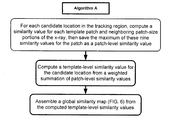
- Algorithm B produces the same template-level similarity values for the global similarity map as in Algorithm A. However, rather than computing a template-level similarity value for a candidate location before moving to the next candidate location, Algorithm B computes a similarity value for a template patch at each candidate location to produce a similarity map over all candidate locations for that template patch. Similar “patch-level similarity maps” are assembled for the remaining template patches. After a patch-level similarity map has been assembled for each of the template patches, the patch-level similarity maps are combined to produce the global similarity map.
- FIG. 5B One embodiment of the Algorithm B steps is summarized in FIG. 5B . Other embodiments are also disclosed.
- the patch-level similarity values that create the patch-level similarity maps are computed with Eq. 1, above, using the patch and the corresponding image intensity values at a candidate location. Only this normalized cross-correlation, or another suitable similarity measure, is computed at the candidate location. The same patch-level similarity value is then computed for the next candidate location, and so on, until a patch-level similarity value has been computed for all candidate locations. These similarity values are saved in the patch-level similarity map for the patch.
- Each patch-level similarity map contains similarity values for all candidate locations, e.g., a similarity value for each pixel coordinate when candidate locations are considered for each pixel coordinate in the tracking region.
- similarity values for patch-size images located directly above, below, to the right, to the left and at the four corners of a patch location that were computed in Algorithm A are already contained in the previously assembled patch-level similarity map.
- Changes to the target shape are accounted for in Algorithm B by saving the maximum of the corresponding nine patch-level similarity values for each of the patch's locations, i.e., the maximum of the similarity value at the patch's location and the similarity values for the locations directly above, below, to the right, to the left and at the four corners, for each of the patch's locations in the patch-level similarity map.
- a “final” patch-level similarity map contains this maximum, or MAX-filter of the similarity values at each candidate location for the patch.
- a mean or median similarity value (as compared to a maximum similarity value) may be saved in the final patch-level similarity map.
- the global similarity map is a weighted summation of the final patch-level similarity maps.
- the sum is normalized (as in Algorithm A) to produce template-level similarity values ranging between ⁇ 1 and 1.
- the summation is made according to the spatial relationship among the patches in the template.
- PLSM 51 (i, j) and PLSM 54 (i, j) are patch-level similarity values at candidate location i, j from the patch 51 map and patch 54 map, respectively; and ⁇ 51 and ⁇ 54 are the standard deviations for patch 51 and patch 54 , respectively.
- a value at a location (i, j ⁇ 2) in PLSM 54 is added to the value at location (i, j) in PLSM 51 .
- a value at location i, j in the final patch-level similarity map for patch 57 PLSM 57 (i, j) is added to PLSM 51+54 (i, j) to create PLSM 51+54+57 (i, j) by adding PLSM 57 (i+2, j ⁇ 1) to PLSM 51+54 (i, j).
- 3D image registration similarity values are computed across three dimensions, rather than two dimensions as described above.
- a 3D MAX-filter of the similarity values computes similarity values for each of a 3D patch-size image portion surrounding a patch in three-dimensional space.
- template-level similarity values are computed for template locations in three-dimensional space.
- the resulting global similarity map therefore, can be thought of as a four-dimensional map of template-level similarity values, in contrast to the three-dimensional contour map produced for a 2D image registration, e.g., as shown in FIG. 6 .
- Image registration processes according to the present disclosure are particularly useful in registering a pre-operative DRR with a live x-ray image of a patient. This type of image registration is often used to assist with locating, or tracking the body of a tumor within a patient during radiation treatment. Depending on the treatment approach, DRR images are registered against one or more live x-rays of the patient.
- DRR images are registered with more than one X-ray image.
- the image-guided, robotic-based radiation treatment CyberKnife System developed by Accu ray Incorporated of California is one example of a treatment system that registers two x-ray images with corresponding DRR images when locating a tumor body in three-dimensional space. Aspects of this system are described in US Pub. No. 2011/0050692.
- Other useful applications for image registration include image guided treatment systems such as gantry based (isocentric) intensity modulated radiotherapy (“IMRT”) systems and 3D conformal radiation treatments.
- IMRT intensity modulated radiotherapy
- Image registration processes according to the present disclosure are also useful in registering pre-operative 3D reference images (e.g., CT image data) or DRR images rendered from those 3D models with live 3D images (e.g., tomosynthetic CBCT or MVCT images) of the patient during an image-guided procedure.
- pre-operative 3D reference images e.g., CT image data
- DRR images rendered from those 3D models e.g., DRR images rendered from those 3D models
- live 3D images e.g., tomosynthetic CBCT or MVCT images
- FIG. 7 shows a geometric relationship between the location of a tumor body 70 in 3D space to two orthogonal projections of that tumor body onto images planes A and B.
- Planes A and B in FIG. 7 represent the orientation of x-ray images generated by x-ray sources S A and S B , respectively.
- DRR images registered with each of the live x-ray images in image planes A and B are used to track motion of the tumor body 70 in three-dimensional space.
- the tumor body 70 location is expressed in terms of a coordinate system having axes Xo, Yo, and Zo with the coordinate system origin at the center of the tumor body 70 .
- the location of the projection of tumor body 70 in the x-ray image planes A and B, i.e., tumor body 70 A and 70 B, respectively, in FIG. 7 is expressed in terms of coordinate systems Xa, Ya, and Za and Xb, Yb, and Zb as shown.
- Image planes A and B are oriented at +/ ⁇ 45 degrees to the Zo or Yo axes, although they may alternatively be oriented at any non-zero angle to these axes.
- the coordinate axes Xo, Xa and Xb are all approximately parallel to each other (each extend normal to the paper) which imposes a constraint on the x-coordinate of the tumor location between the two x-ray images. Since the Xa and Xb axes are parallel to each other, the true x-coordinate for the tumor body must be the same for each image plane. This shared x-coordinate requirement may be exploited during the image registration process.
- the shared x-coordinate requirement may be enforced after global similarity maps have been generated for each image plane, as a way to confirm the location of the tumor body or to resolve situations where there are no distinct maximums in one or both global similarity maps.
- a comparison of the Y-axis projections of the global similarity maps onto Z-X planes can be used to resolve these situations by choosing the x-coordinate where a maximum is found in both global similarity maps, or where the combined maps yield an x-coordinate having a distinct maximum.
- FIGS. 8A and 8B show Y-axis projections onto the Z-X planes for global similarity maps generated from image planes A and B, respectively.
- There are two maximums appearing in FIG. 8B namely the maximums at x-coordinates xb 1 and xb 2 . Since these template-level similarity values are very similar to each other, the actual tumor body location may be at either xb 1 or xb 2 .
- FIG. 8A shows the x-coordinates for image plane A. Here there is a distinct maximum shown at xa 2 , but there alternatively may be two similar maximums at xa 1 and xa 2 as in the case of FIG. 8B .
- the ambiguity in x-coordinate location for the tumor body 70 can be resolved by choosing the x-coordinate where there is a maximum in both of the Y-axis projected maps, i.e., x-coordinates xb 2 , xa 2 .
- x-coordinates xb 2 , xa 2 when there is no discernable maximum in either image, or no shared x-coordinate, a distinct maximum may be revealed from the combined maps.
- the true x-coordinate for the tumor body may be found from the sum of z-coordinates for the two maps.
- the shared x-coordinate requirement may alternatively be enforced after only one of the global similarity maps has been generated.
- the x-coordinate extracted from the global similarity map for one image plane is used to restrict the search space for the maximum similarity value in the other image plane (image plane B). Since the x-coordinate must be the same for both images, the candidate locations in image plane B can be limited to those that fall along the x-coordinate extracted from image plane A.
- the search for the tumor body in image plane B can amount to essentially a 1D search over y-coordinate values.
- an image registration that takes into account a shared-axis constraint can be applied to other imaging geometries, and is not limited to the stereoscopic geometry illustrated in FIG. 7 .
- Such other uses are contemplated, using either a search algorithm that computes similarity values according to the disclosure, or other image registration algorithms that seek to register multiple images where the image planes are arranged in such a manner as to impose one or more geometric constraints on the target's location in image planes.
- a visual depiction of the global probability map may be made in terms of either a 3D contoured surface ( FIG. 6 ) or as a two-dimensional plot with the distribution of template-level similarity values (TSV) differentiated by color.
- TSV template-level similarity values
- the TSV distribution in the global probability map may be expressed in a manner analogous to a 2D thermal image, which displays different colors to reflect a temperature distribution.
- higher TSV are depicted using shades of orange and yellow, with shades of white (the “hot spots”) corresponding to the maximum TSV.
- lower TSV values may be depicted as shades of blue and black.
- a global probability map displayed in terms of different colors will hereinafter be referred to as a “thermal image of the TSV”.
- a thermal image of the TSV permits a visual comparison between the expected location for a structure (i.e., the maximum TSV or “hot spot”) and the structure that appears at both the corresponding location and nearby locations in the 2D image, e.g., an x-ray.
- the visual comparison with the thermal image of the TSV facilitates a confidence measure when concluding that the target's actual location was found, or more quickly identifies situations where the maximum TSV should not be relied on to locate the target.
- an operator uses a computer monitor connected to a processor, an operator displays the 2D image (or selects a 2D view from a 3D image by rotating the image or moving along a coordinate axis in 3D space) of the patient on the monitor.
- the thermal image of the TSV is aligned with the 2D image. For example, when candidate locations are spaced by a pixel distance each pixel coordinate in the x-ray is aligned with the corresponding TSV color.
- a semi-transparent color is displayed so that both the x-ray and thermal image of the TSV can be seen at the same time on the monitor.
- This arrangement provides the operator with a visual display of the tracking region showing a distribution of colors over the grayscale x-ray image.
- the operator searches for the hot spots and compares the hot spots to the underlying structure and nearby structure depicted in the x-ray. If the expected location of the target were to correspond to the actual location of the target, then the hot spot would appear on the x-ray at the same location of the target as the reference location chosen for the target in the reference image, e.g., the target's geometric center in the DRR. This type of visual comparison provides an additional confidence measure that the true location of the target was found. Conversely, if a hot spot does not match-up with the grayscale image expected at or nearby the hot spot, this may quickly indicate that the computed maximum TSV is not a reliable indicator of the target's location.
- the methods described herein are not limited to use only with medical diagnostic imaging and treatment.
- the methods and apparatus herein may be used in applications outside of the medical technology field, such as industrial imaging and non-destructive testing of materials (e.g., motor blocks in the automotive industry, airframes in the aviation industry, welds in the construction industry and drill cores in the petroleum industry) and seismic surveying.
- treatment may refer generally to the application of radiation beam(s).
- the disclosure is intended to apply to computer software and/or hardware adapted for, in addition to methods of image registration.
- the techniques described may constitute machine-executable instructions embodied within a machine (e.g., computer) readable storage medium, that when executed by a machine will cause the machine to perform the operations described. Additionally, the processes may be embodied within hardware, such as an application specific integrated circuit (“ASIC”) or the like.
- ASIC application specific integrated circuit
- a computer-readable storage medium includes any mechanism that provides (i.e., stores) information in a non-transient form accessible by a machine (e.g., a computer, network device, personal digital assistant, mobile device, manufacturing tool, any device with a set of one or more processors, etc.).
- a computer-readable storage medium includes recordable/non-recordable media (e.g., read only memory (ROM), random access memory (RAM), magnetic disk storage media, optical storage media, flash memory devices, etc.).
Abstract
Description
Σ[(f(x,y)−F)(t(x,y)−T)](δfδt)−1 (Eq. 1)
TSV=ΣδiPSVi[Σδi]−1 , i=1 . . . m (Eq. 2)
PLSM51+54(i,j)=[δ51δ54]−1(δ51PLSM51(i,j)+δ54PLSM54(i,j−2)) (Eq. 3)
Claims (26)
Priority Applications (2)
| Application Number | Priority Date | Filing Date | Title |
|---|---|---|---|
| US13/183,305 US8818105B2 (en) | 2011-07-14 | 2011-07-14 | Image registration for image-guided surgery |
| PCT/US2012/042267 WO2013009427A2 (en) | 2011-07-14 | 2012-06-13 | Image registration for image-guided surgery |
Applications Claiming Priority (1)
| Application Number | Priority Date | Filing Date | Title |
|---|---|---|---|
| US13/183,305 US8818105B2 (en) | 2011-07-14 | 2011-07-14 | Image registration for image-guided surgery |
Publications (2)
| Publication Number | Publication Date |
|---|---|
| US20130016889A1 US20130016889A1 (en) | 2013-01-17 |
| US8818105B2 true US8818105B2 (en) | 2014-08-26 |
Family
ID=46551848
Family Applications (1)
| Application Number | Title | Priority Date | Filing Date |
|---|---|---|---|
| US13/183,305 Active 2033-04-03 US8818105B2 (en) | 2011-07-14 | 2011-07-14 | Image registration for image-guided surgery |
Country Status (2)
| Country | Link |
|---|---|
| US (1) | US8818105B2 (en) |
| WO (1) | WO2013009427A2 (en) |
Cited By (110)
| Publication number | Priority date | Publication date | Assignee | Title |
|---|---|---|---|---|
| US9078685B2 (en) | 2007-02-16 | 2015-07-14 | Globus Medical, Inc. | Method and system for performing invasive medical procedures using a surgical robot |
| US9782229B2 (en) | 2007-02-16 | 2017-10-10 | Globus Medical, Inc. | Surgical robot platform |
| US10080615B2 (en) | 2015-08-12 | 2018-09-25 | Globus Medical, Inc. | Devices and methods for temporary mounting of parts to bone |
| US10117632B2 (en) | 2016-02-03 | 2018-11-06 | Globus Medical, Inc. | Portable medical imaging system with beam scanning collimator |
| US10136954B2 (en) | 2012-06-21 | 2018-11-27 | Globus Medical, Inc. | Surgical tool systems and method |
| CN109344329A (en) * | 2018-10-17 | 2019-02-15 | 中山大学 | A kind of user preference collaborative recommendation method for improveing Widrow-Hoff network |
| US10231791B2 (en) | 2012-06-21 | 2019-03-19 | Globus Medical, Inc. | Infrared signal based position recognition system for use with a robot-assisted surgery |
| US10292778B2 (en) | 2014-04-24 | 2019-05-21 | Globus Medical, Inc. | Surgical instrument holder for use with a robotic surgical system |
| US10342996B2 (en) | 2016-08-29 | 2019-07-09 | Accuray Incorporated | Online angle selection in rotational imaging and tracking systems |
| US10350013B2 (en) | 2012-06-21 | 2019-07-16 | Globus Medical, Inc. | Surgical tool systems and methods |
| US10357257B2 (en) | 2014-07-14 | 2019-07-23 | KB Medical SA | Anti-skid surgical instrument for use in preparing holes in bone tissue |
| US10357184B2 (en) | 2012-06-21 | 2019-07-23 | Globus Medical, Inc. | Surgical tool systems and method |
| US10420616B2 (en) | 2017-01-18 | 2019-09-24 | Globus Medical, Inc. | Robotic navigation of robotic surgical systems |
| US10448910B2 (en) | 2016-02-03 | 2019-10-22 | Globus Medical, Inc. | Portable medical imaging system |
| US10532224B2 (en) | 2016-08-29 | 2020-01-14 | Accuray Incorporated | Offline angle selection in rotational imaging and tracking systems |
| US10546423B2 (en) | 2015-02-03 | 2020-01-28 | Globus Medical, Inc. | Surgeon head-mounted display apparatuses |
| US10548620B2 (en) | 2014-01-15 | 2020-02-04 | Globus Medical, Inc. | Notched apparatus for guidance of an insertable instrument along an axis during spinal surgery |
| US10555782B2 (en) | 2015-02-18 | 2020-02-11 | Globus Medical, Inc. | Systems and methods for performing minimally invasive spinal surgery with a robotic surgical system using a percutaneous technique |
| US10573023B2 (en) | 2018-04-09 | 2020-02-25 | Globus Medical, Inc. | Predictive visualization of medical imaging scanner component movement |
| US10569794B2 (en) | 2015-10-13 | 2020-02-25 | Globus Medical, Inc. | Stabilizer wheel assembly and methods of use |
| US10624710B2 (en) | 2012-06-21 | 2020-04-21 | Globus Medical, Inc. | System and method for measuring depth of instrumentation |
| US10646280B2 (en) | 2012-06-21 | 2020-05-12 | Globus Medical, Inc. | System and method for surgical tool insertion using multiaxis force and moment feedback |
| US10646283B2 (en) | 2018-02-19 | 2020-05-12 | Globus Medical Inc. | Augmented reality navigation systems for use with robotic surgical systems and methods of their use |
| US10646298B2 (en) | 2015-07-31 | 2020-05-12 | Globus Medical, Inc. | Robot arm and methods of use |
| US10653497B2 (en) | 2006-02-16 | 2020-05-19 | Globus Medical, Inc. | Surgical tool systems and methods |
| US10660712B2 (en) | 2011-04-01 | 2020-05-26 | Globus Medical Inc. | Robotic system and method for spinal and other surgeries |
| US10675094B2 (en) | 2017-07-21 | 2020-06-09 | Globus Medical Inc. | Robot surgical platform |
| US10687905B2 (en) | 2015-08-31 | 2020-06-23 | KB Medical SA | Robotic surgical systems and methods |
| US10758315B2 (en) | 2012-06-21 | 2020-09-01 | Globus Medical Inc. | Method and system for improving 2D-3D registration convergence |
| US10765438B2 (en) | 2014-07-14 | 2020-09-08 | KB Medical SA | Anti-skid surgical instrument for use in preparing holes in bone tissue |
| US10799298B2 (en) | 2012-06-21 | 2020-10-13 | Globus Medical Inc. | Robotic fluoroscopic navigation |
| US10806471B2 (en) | 2017-01-18 | 2020-10-20 | Globus Medical, Inc. | Universal instrument guide for robotic surgical systems, surgical instrument systems, and methods of their use |
| US10813704B2 (en) | 2013-10-04 | 2020-10-27 | Kb Medical, Sa | Apparatus and systems for precise guidance of surgical tools |
| US10828120B2 (en) | 2014-06-19 | 2020-11-10 | Kb Medical, Sa | Systems and methods for performing minimally invasive surgery |
| US10842453B2 (en) | 2016-02-03 | 2020-11-24 | Globus Medical, Inc. | Portable medical imaging system |
| US10842461B2 (en) | 2012-06-21 | 2020-11-24 | Globus Medical, Inc. | Systems and methods of checking registrations for surgical systems |
| US10866119B2 (en) | 2016-03-14 | 2020-12-15 | Globus Medical, Inc. | Metal detector for detecting insertion of a surgical device into a hollow tube |
| US10864057B2 (en) | 2017-01-18 | 2020-12-15 | Kb Medical, Sa | Universal instrument guide for robotic surgical systems, surgical instrument systems, and methods of their use |
| US10874466B2 (en) | 2012-06-21 | 2020-12-29 | Globus Medical, Inc. | System and method for surgical tool insertion using multiaxis force and moment feedback |
| US10893912B2 (en) | 2006-02-16 | 2021-01-19 | Globus Medical Inc. | Surgical tool systems and methods |
| US10898252B2 (en) | 2017-11-09 | 2021-01-26 | Globus Medical, Inc. | Surgical robotic systems for bending surgical rods, and related methods and devices |
| US10925681B2 (en) | 2015-07-31 | 2021-02-23 | Globus Medical Inc. | Robot arm and methods of use |
| US10939968B2 (en) | 2014-02-11 | 2021-03-09 | Globus Medical Inc. | Sterile handle for controlling a robotic surgical system from a sterile field |
| US10973594B2 (en) | 2015-09-14 | 2021-04-13 | Globus Medical, Inc. | Surgical robotic systems and methods thereof |
| US11039893B2 (en) | 2016-10-21 | 2021-06-22 | Globus Medical, Inc. | Robotic surgical systems |
| US11045267B2 (en) | 2012-06-21 | 2021-06-29 | Globus Medical, Inc. | Surgical robotic automation with tracking markers |
| US11045179B2 (en) | 2019-05-20 | 2021-06-29 | Global Medical Inc | Robot-mounted retractor system |
| US11058378B2 (en) | 2016-02-03 | 2021-07-13 | Globus Medical, Inc. | Portable medical imaging system |
| US11071594B2 (en) | 2017-03-16 | 2021-07-27 | KB Medical SA | Robotic navigation of robotic surgical systems |
| US11103316B2 (en) | 2014-12-02 | 2021-08-31 | Globus Medical Inc. | Robot assisted volume removal during surgery |
| US11116576B2 (en) | 2012-06-21 | 2021-09-14 | Globus Medical Inc. | Dynamic reference arrays and methods of use |
| US11134862B2 (en) | 2017-11-10 | 2021-10-05 | Globus Medical, Inc. | Methods of selecting surgical implants and related devices |
| US11153555B1 (en) | 2020-05-08 | 2021-10-19 | Globus Medical Inc. | Extended reality headset camera system for computer assisted navigation in surgery |
| US11207150B2 (en) | 2020-02-19 | 2021-12-28 | Globus Medical, Inc. | Displaying a virtual model of a planned instrument attachment to ensure correct selection of physical instrument attachment |
| US11253327B2 (en) | 2012-06-21 | 2022-02-22 | Globus Medical, Inc. | Systems and methods for automatically changing an end-effector on a surgical robot |
| US11253216B2 (en) | 2020-04-28 | 2022-02-22 | Globus Medical Inc. | Fixtures for fluoroscopic imaging systems and related navigation systems and methods |
| US11278360B2 (en) | 2018-11-16 | 2022-03-22 | Globus Medical, Inc. | End-effectors for surgical robotic systems having sealed optical components |
| US11298196B2 (en) | 2012-06-21 | 2022-04-12 | Globus Medical Inc. | Surgical robotic automation with tracking markers and controlled tool advancement |
| US11317978B2 (en) | 2019-03-22 | 2022-05-03 | Globus Medical, Inc. | System for neuronavigation registration and robotic trajectory guidance, robotic surgery, and related methods and devices |
| US11317971B2 (en) | 2012-06-21 | 2022-05-03 | Globus Medical, Inc. | Systems and methods related to robotic guidance in surgery |
| US11317973B2 (en) | 2020-06-09 | 2022-05-03 | Globus Medical, Inc. | Camera tracking bar for computer assisted navigation during surgery |
| US11337742B2 (en) | 2018-11-05 | 2022-05-24 | Globus Medical Inc | Compliant orthopedic driver |
| US11357548B2 (en) | 2017-11-09 | 2022-06-14 | Globus Medical, Inc. | Robotic rod benders and related mechanical and motor housings |
| US11382699B2 (en) | 2020-02-10 | 2022-07-12 | Globus Medical Inc. | Extended reality visualization of optical tool tracking volume for computer assisted navigation in surgery |
| US11382700B2 (en) | 2020-05-08 | 2022-07-12 | Globus Medical Inc. | Extended reality headset tool tracking and control |
| US11382713B2 (en) | 2020-06-16 | 2022-07-12 | Globus Medical, Inc. | Navigated surgical system with eye to XR headset display calibration |
| US11382549B2 (en) | 2019-03-22 | 2022-07-12 | Globus Medical, Inc. | System for neuronavigation registration and robotic trajectory guidance, and related methods and devices |
| US11395706B2 (en) | 2012-06-21 | 2022-07-26 | Globus Medical Inc. | Surgical robot platform |
| US11399900B2 (en) | 2012-06-21 | 2022-08-02 | Globus Medical, Inc. | Robotic systems providing co-registration using natural fiducials and related methods |
| US11419616B2 (en) | 2019-03-22 | 2022-08-23 | Globus Medical, Inc. | System for neuronavigation registration and robotic trajectory guidance, robotic surgery, and related methods and devices |
| US11426178B2 (en) | 2019-09-27 | 2022-08-30 | Globus Medical Inc. | Systems and methods for navigating a pin guide driver |
| US11439444B1 (en) | 2021-07-22 | 2022-09-13 | Globus Medical, Inc. | Screw tower and rod reduction tool |
| US11464581B2 (en) | 2020-01-28 | 2022-10-11 | Globus Medical, Inc. | Pose measurement chaining for extended reality surgical navigation in visible and near infrared spectrums |
| US11483531B2 (en) | 2020-05-26 | 2022-10-25 | Unify Medical, Inc. | Generation of three-dimensional images with digital magnification |
| US11510750B2 (en) | 2020-05-08 | 2022-11-29 | Globus Medical, Inc. | Leveraging two-dimensional digital imaging and communication in medicine imagery in three-dimensional extended reality applications |
| US11510684B2 (en) | 2019-10-14 | 2022-11-29 | Globus Medical, Inc. | Rotary motion passive end effector for surgical robots in orthopedic surgeries |
| US11523785B2 (en) | 2020-09-24 | 2022-12-13 | Globus Medical, Inc. | Increased cone beam computed tomography volume length without requiring stitching or longitudinal C-arm movement |
| US11571265B2 (en) | 2019-03-22 | 2023-02-07 | Globus Medical Inc. | System for neuronavigation registration and robotic trajectory guidance, robotic surgery, and related methods and devices |
| US11571171B2 (en) | 2019-09-24 | 2023-02-07 | Globus Medical, Inc. | Compound curve cable chain |
| US11589771B2 (en) | 2012-06-21 | 2023-02-28 | Globus Medical Inc. | Method for recording probe movement and determining an extent of matter removed |
| US11602402B2 (en) | 2018-12-04 | 2023-03-14 | Globus Medical, Inc. | Drill guide fixtures, cranial insertion fixtures, and related methods and robotic systems |
| US11607149B2 (en) | 2012-06-21 | 2023-03-21 | Globus Medical Inc. | Surgical tool systems and method |
| US11628023B2 (en) | 2019-07-10 | 2023-04-18 | Globus Medical, Inc. | Robotic navigational system for interbody implants |
| US11671703B2 (en) | 2017-04-14 | 2023-06-06 | Unify Medical, Inc. | System and apparatus for co-registration and correlation between multi-modal imagery and method for same |
| US11710249B2 (en) | 2019-12-20 | 2023-07-25 | Unify Medical, Inc. | Generation of three-dimensional scans for intraoperative imaging |
| US11717350B2 (en) | 2020-11-24 | 2023-08-08 | Globus Medical Inc. | Methods for robotic assistance and navigation in spinal surgery and related systems |
| US11737831B2 (en) | 2020-09-02 | 2023-08-29 | Globus Medical Inc. | Surgical object tracking template generation for computer assisted navigation during surgical procedure |
| US11744655B2 (en) | 2018-12-04 | 2023-09-05 | Globus Medical, Inc. | Drill guide fixtures, cranial insertion fixtures, and related methods and robotic systems |
| US11786324B2 (en) | 2012-06-21 | 2023-10-17 | Globus Medical, Inc. | Surgical robotic automation with tracking markers |
| US11793588B2 (en) | 2020-07-23 | 2023-10-24 | Globus Medical, Inc. | Sterile draping of robotic arms |
| US11793570B2 (en) | 2012-06-21 | 2023-10-24 | Globus Medical Inc. | Surgical robotic automation with tracking markers |
| US11794338B2 (en) | 2017-11-09 | 2023-10-24 | Globus Medical Inc. | Robotic rod benders and related mechanical and motor housings |
| US11806084B2 (en) | 2019-03-22 | 2023-11-07 | Globus Medical, Inc. | System for neuronavigation registration and robotic trajectory guidance, and related methods and devices |
| US11850009B2 (en) | 2021-07-06 | 2023-12-26 | Globus Medical, Inc. | Ultrasonic robotic surgical navigation |
| US11861856B2 (en) | 2020-06-27 | 2024-01-02 | Shanghai United Imaging Healthcare Co., Ltd. | Systems and methods for image processing |
| US11857266B2 (en) | 2012-06-21 | 2024-01-02 | Globus Medical, Inc. | System for a surveillance marker in robotic-assisted surgery |
| US11857149B2 (en) | 2012-06-21 | 2024-01-02 | Globus Medical, Inc. | Surgical robotic systems with target trajectory deviation monitoring and related methods |
| US11864857B2 (en) | 2019-09-27 | 2024-01-09 | Globus Medical, Inc. | Surgical robot with passive end effector |
| US11864839B2 (en) | 2012-06-21 | 2024-01-09 | Globus Medical Inc. | Methods of adjusting a virtual implant and related surgical navigation systems |
| US11864745B2 (en) | 2012-06-21 | 2024-01-09 | Globus Medical, Inc. | Surgical robotic system with retractor |
| US11877807B2 (en) | 2020-07-10 | 2024-01-23 | Globus Medical, Inc | Instruments for navigated orthopedic surgeries |
| US11883217B2 (en) | 2016-02-03 | 2024-01-30 | Globus Medical, Inc. | Portable medical imaging system and method |
| US11890066B2 (en) | 2019-09-30 | 2024-02-06 | Globus Medical, Inc | Surgical robot with passive end effector |
| US11896446B2 (en) | 2012-06-21 | 2024-02-13 | Globus Medical, Inc | Surgical robotic automation with tracking markers |
| US11911112B2 (en) | 2020-10-27 | 2024-02-27 | Globus Medical, Inc. | Robotic navigational system |
| US11911115B2 (en) | 2021-12-20 | 2024-02-27 | Globus Medical Inc. | Flat panel registration fixture and method of using same |
| US11918313B2 (en) | 2019-03-15 | 2024-03-05 | Globus Medical Inc. | Active end effectors for surgical robots |
| US11941814B2 (en) | 2020-11-04 | 2024-03-26 | Globus Medical Inc. | Auto segmentation using 2-D images taken during 3-D imaging spin |
| US11944325B2 (en) | 2019-03-22 | 2024-04-02 | Globus Medical, Inc. | System for neuronavigation registration and robotic trajectory guidance, robotic surgery, and related methods and devices |
| US11963755B2 (en) | 2022-11-21 | 2024-04-23 | Globus Medical Inc. | Apparatus for recording probe movement |
Families Citing this family (11)
| Publication number | Priority date | Publication date | Assignee | Title |
|---|---|---|---|---|
| US20130101193A1 (en) * | 2011-10-20 | 2013-04-25 | Jong Beom Ra | Positron Emission Tomography and Method for Correcting Attenuation of PET Image Using Magnetic Resonance Image |
| JP6376873B2 (en) | 2014-07-16 | 2018-08-22 | キヤノン株式会社 | Image processing apparatus, image processing method, and program |
| US20160030008A1 (en) * | 2014-07-30 | 2016-02-04 | General Electric Company | System and method for registering ultrasound information to an x-ray image |
| WO2016175755A1 (en) * | 2015-04-28 | 2016-11-03 | Siemens Healthcare Gmbh | METHOD AND SYSTEM FOR SYNTHESIZING VIRTUAL HIGH DOSE OR HIGH kV COMPUTED TOMOGRAPHY IMAGES FROM LOW DOSE OR LOW kV COMPUTED TOMOGRAPHY IMAGES |
| US9727785B2 (en) * | 2015-06-18 | 2017-08-08 | The Boeing Company | Method and apparatus for tracking targets |
| US9715639B2 (en) | 2015-06-18 | 2017-07-25 | The Boeing Company | Method and apparatus for detecting targets |
| JP6456550B2 (en) * | 2015-09-01 | 2019-01-23 | コーニンクレッカ フィリップス エヌ ヴェKoninklijke Philips N.V. | Device for displaying medical image data of a body part |
| US11443441B2 (en) | 2017-02-24 | 2022-09-13 | Brainlab Ag | Deep inspiration breath-hold setup using x-ray imaging |
| CN108361020B (en) * | 2018-04-03 | 2021-04-23 | 中煤科工集团西安研究院有限公司 | Virtual instrument-based diagnosis and protection device and method for tunnel drilling machine |
| CN111932549B (en) * | 2020-06-28 | 2023-03-24 | 山东师范大学 | SP-FCN-based MRI brain tumor image segmentation system and method |
| CN114596344B (en) * | 2020-12-04 | 2024-03-19 | 杭州三坛医疗科技有限公司 | Medical image registration parameter determination method, device, equipment and storage medium |
Citations (9)
| Publication number | Priority date | Publication date | Assignee | Title |
|---|---|---|---|---|
| US6041140A (en) * | 1994-10-04 | 2000-03-21 | Synthonics, Incorporated | Apparatus for interactive image correlation for three dimensional image production |
| US7120276B1 (en) | 1999-03-19 | 2006-10-10 | Mirada Solutions Limited | Method and apparatus for image processing |
| US20070248214A1 (en) | 2006-04-25 | 2007-10-25 | Accuray Incorporated | Energy monitoring target for x-ray dose-rate control |
| US20080069453A1 (en) * | 2006-09-05 | 2008-03-20 | Hitachi High-Technologies Corporation | Inspection Apparatus Using Template Matching Method Using Similarity Distribution |
| US20080310755A1 (en) | 2007-06-14 | 2008-12-18 | Microsoft Corporation | Capturing long-range correlations in patch models |
| US20100104158A1 (en) | 2006-12-21 | 2010-04-29 | Eli Shechtman | Method and apparatus for matching local self-similarities |
| US7894649B2 (en) | 2006-11-02 | 2011-02-22 | Accuray Incorporated | Target tracking using direct target registration |
| US20110050692A1 (en) | 2009-09-01 | 2011-03-03 | Accuray Incorporated | Interpolating and rendering sub-phases of a 4d dataset |
| US7961838B2 (en) | 2005-05-17 | 2011-06-14 | Varian Medical Systems, Inc. | Computerized tomography image reconstruction |
Family Cites Families (4)
| Publication number | Priority date | Publication date | Assignee | Title |
|---|---|---|---|---|
| US7110603B2 (en) * | 2003-04-16 | 2006-09-19 | Lee Shih-Jong J | Fast invariant matching using template decomposition and synthesis |
| US7231076B2 (en) * | 2004-06-30 | 2007-06-12 | Accuray, Inc. | ROI selection in image registration |
| US8077936B2 (en) | 2005-06-02 | 2011-12-13 | Accuray Incorporated | Treatment planning software and corresponding user interface |
| US7933380B2 (en) | 2007-09-28 | 2011-04-26 | Varian Medical Systems International Ag | Radiation systems and methods using deformable image registration |
-
2011
- 2011-07-14 US US13/183,305 patent/US8818105B2/en active Active
-
2012
- 2012-06-13 WO PCT/US2012/042267 patent/WO2013009427A2/en active Application Filing
Patent Citations (9)
| Publication number | Priority date | Publication date | Assignee | Title |
|---|---|---|---|---|
| US6041140A (en) * | 1994-10-04 | 2000-03-21 | Synthonics, Incorporated | Apparatus for interactive image correlation for three dimensional image production |
| US7120276B1 (en) | 1999-03-19 | 2006-10-10 | Mirada Solutions Limited | Method and apparatus for image processing |
| US7961838B2 (en) | 2005-05-17 | 2011-06-14 | Varian Medical Systems, Inc. | Computerized tomography image reconstruction |
| US20070248214A1 (en) | 2006-04-25 | 2007-10-25 | Accuray Incorporated | Energy monitoring target for x-ray dose-rate control |
| US20080069453A1 (en) * | 2006-09-05 | 2008-03-20 | Hitachi High-Technologies Corporation | Inspection Apparatus Using Template Matching Method Using Similarity Distribution |
| US7894649B2 (en) | 2006-11-02 | 2011-02-22 | Accuray Incorporated | Target tracking using direct target registration |
| US20100104158A1 (en) | 2006-12-21 | 2010-04-29 | Eli Shechtman | Method and apparatus for matching local self-similarities |
| US20080310755A1 (en) | 2007-06-14 | 2008-12-18 | Microsoft Corporation | Capturing long-range correlations in patch models |
| US20110050692A1 (en) | 2009-09-01 | 2011-03-03 | Accuray Incorporated | Interpolating and rendering sub-phases of a 4d dataset |
Non-Patent Citations (1)
| Title |
|---|
| Kilby et al., "The CyberKnife® Robotic Radiosurgery System in 2010", Tech. in Cancer Res. and Treatment vol. 9, No. 5, pp. 433-452 (2010). |
Cited By (199)
| Publication number | Priority date | Publication date | Assignee | Title |
|---|---|---|---|---|
| US10653497B2 (en) | 2006-02-16 | 2020-05-19 | Globus Medical, Inc. | Surgical tool systems and methods |
| US11628039B2 (en) | 2006-02-16 | 2023-04-18 | Globus Medical Inc. | Surgical tool systems and methods |
| US10893912B2 (en) | 2006-02-16 | 2021-01-19 | Globus Medical Inc. | Surgical tool systems and methods |
| US9782229B2 (en) | 2007-02-16 | 2017-10-10 | Globus Medical, Inc. | Surgical robot platform |
| US10172678B2 (en) | 2007-02-16 | 2019-01-08 | Globus Medical, Inc. | Method and system for performing invasive medical procedures using a surgical robot |
| US9078685B2 (en) | 2007-02-16 | 2015-07-14 | Globus Medical, Inc. | Method and system for performing invasive medical procedures using a surgical robot |
| US11202681B2 (en) | 2011-04-01 | 2021-12-21 | Globus Medical, Inc. | Robotic system and method for spinal and other surgeries |
| US11744648B2 (en) | 2011-04-01 | 2023-09-05 | Globus Medicall, Inc. | Robotic system and method for spinal and other surgeries |
| US10660712B2 (en) | 2011-04-01 | 2020-05-26 | Globus Medical Inc. | Robotic system and method for spinal and other surgeries |
| US11109922B2 (en) | 2012-06-21 | 2021-09-07 | Globus Medical, Inc. | Surgical tool systems and method |
| US10874466B2 (en) | 2012-06-21 | 2020-12-29 | Globus Medical, Inc. | System and method for surgical tool insertion using multiaxis force and moment feedback |
| US11331153B2 (en) | 2012-06-21 | 2022-05-17 | Globus Medical, Inc. | Surgical robot platform |
| US10357184B2 (en) | 2012-06-21 | 2019-07-23 | Globus Medical, Inc. | Surgical tool systems and method |
| US11395706B2 (en) | 2012-06-21 | 2022-07-26 | Globus Medical Inc. | Surgical robot platform |
| US11864745B2 (en) | 2012-06-21 | 2024-01-09 | Globus Medical, Inc. | Surgical robotic system with retractor |
| US11864839B2 (en) | 2012-06-21 | 2024-01-09 | Globus Medical Inc. | Methods of adjusting a virtual implant and related surgical navigation systems |
| US10485617B2 (en) | 2012-06-21 | 2019-11-26 | Globus Medical, Inc. | Surgical robot platform |
| US11857149B2 (en) | 2012-06-21 | 2024-01-02 | Globus Medical, Inc. | Surgical robotic systems with target trajectory deviation monitoring and related methods |
| US10531927B2 (en) | 2012-06-21 | 2020-01-14 | Globus Medical, Inc. | Methods for performing invasive medical procedures using a surgical robot |
| US11317971B2 (en) | 2012-06-21 | 2022-05-03 | Globus Medical, Inc. | Systems and methods related to robotic guidance in surgery |
| US11399900B2 (en) | 2012-06-21 | 2022-08-02 | Globus Medical, Inc. | Robotic systems providing co-registration using natural fiducials and related methods |
| US11298196B2 (en) | 2012-06-21 | 2022-04-12 | Globus Medical Inc. | Surgical robotic automation with tracking markers and controlled tool advancement |
| US11857266B2 (en) | 2012-06-21 | 2024-01-02 | Globus Medical, Inc. | System for a surveillance marker in robotic-assisted surgery |
| US11284949B2 (en) | 2012-06-21 | 2022-03-29 | Globus Medical, Inc. | Surgical robot platform |
| US11439471B2 (en) | 2012-06-21 | 2022-09-13 | Globus Medical, Inc. | Surgical tool system and method |
| US10624710B2 (en) | 2012-06-21 | 2020-04-21 | Globus Medical, Inc. | System and method for measuring depth of instrumentation |
| US10136954B2 (en) | 2012-06-21 | 2018-11-27 | Globus Medical, Inc. | Surgical tool systems and method |
| US10646280B2 (en) | 2012-06-21 | 2020-05-12 | Globus Medical, Inc. | System and method for surgical tool insertion using multiaxis force and moment feedback |
| US11819365B2 (en) | 2012-06-21 | 2023-11-21 | Globus Medical, Inc. | System and method for measuring depth of instrumentation |
| US11253327B2 (en) | 2012-06-21 | 2022-02-22 | Globus Medical, Inc. | Systems and methods for automatically changing an end-effector on a surgical robot |
| US11589771B2 (en) | 2012-06-21 | 2023-02-28 | Globus Medical Inc. | Method for recording probe movement and determining an extent of matter removed |
| US11896446B2 (en) | 2012-06-21 | 2024-02-13 | Globus Medical, Inc | Surgical robotic automation with tracking markers |
| US11191598B2 (en) | 2012-06-21 | 2021-12-07 | Globus Medical, Inc. | Surgical robot platform |
| US11819283B2 (en) | 2012-06-21 | 2023-11-21 | Globus Medical Inc. | Systems and methods related to robotic guidance in surgery |
| US11026756B2 (en) | 2012-06-21 | 2021-06-08 | Globus Medical, Inc. | Surgical robot platform |
| US11045267B2 (en) | 2012-06-21 | 2021-06-29 | Globus Medical, Inc. | Surgical robotic automation with tracking markers |
| US10758315B2 (en) | 2012-06-21 | 2020-09-01 | Globus Medical Inc. | Method and system for improving 2D-3D registration convergence |
| US11607149B2 (en) | 2012-06-21 | 2023-03-21 | Globus Medical Inc. | Surgical tool systems and method |
| US11911225B2 (en) | 2012-06-21 | 2024-02-27 | Globus Medical Inc. | Method and system for improving 2D-3D registration convergence |
| US10799298B2 (en) | 2012-06-21 | 2020-10-13 | Globus Medical Inc. | Robotic fluoroscopic navigation |
| US11793570B2 (en) | 2012-06-21 | 2023-10-24 | Globus Medical Inc. | Surgical robotic automation with tracking markers |
| US11786324B2 (en) | 2012-06-21 | 2023-10-17 | Globus Medical, Inc. | Surgical robotic automation with tracking markers |
| US11690687B2 (en) | 2012-06-21 | 2023-07-04 | Globus Medical Inc. | Methods for performing medical procedures using a surgical robot |
| US11684433B2 (en) | 2012-06-21 | 2023-06-27 | Globus Medical Inc. | Surgical tool systems and method |
| US11135022B2 (en) | 2012-06-21 | 2021-10-05 | Globus Medical, Inc. | Surgical robot platform |
| US10835328B2 (en) | 2012-06-21 | 2020-11-17 | Globus Medical, Inc. | Surgical robot platform |
| US10835326B2 (en) | 2012-06-21 | 2020-11-17 | Globus Medical Inc. | Surgical robot platform |
| US11116576B2 (en) | 2012-06-21 | 2021-09-14 | Globus Medical Inc. | Dynamic reference arrays and methods of use |
| US10842461B2 (en) | 2012-06-21 | 2020-11-24 | Globus Medical, Inc. | Systems and methods of checking registrations for surgical systems |
| US10231791B2 (en) | 2012-06-21 | 2019-03-19 | Globus Medical, Inc. | Infrared signal based position recognition system for use with a robot-assisted surgery |
| US11103320B2 (en) | 2012-06-21 | 2021-08-31 | Globus Medical, Inc. | Infrared signal based position recognition system for use with a robot-assisted surgery |
| US10350013B2 (en) | 2012-06-21 | 2019-07-16 | Globus Medical, Inc. | Surgical tool systems and methods |
| US11103317B2 (en) | 2012-06-21 | 2021-08-31 | Globus Medical, Inc. | Surgical robot platform |
| US10639112B2 (en) | 2012-06-21 | 2020-05-05 | Globus Medical, Inc. | Infrared signal based position recognition system for use with a robot-assisted surgery |
| US11744657B2 (en) | 2012-06-21 | 2023-09-05 | Globus Medical, Inc. | Infrared signal based position recognition system for use with a robot-assisted surgery |
| US10912617B2 (en) | 2012-06-21 | 2021-02-09 | Globus Medical, Inc. | Surgical robot platform |
| US11684437B2 (en) | 2012-06-21 | 2023-06-27 | Globus Medical Inc. | Systems and methods for automatically changing an end-effector on a surgical robot |
| US11684431B2 (en) | 2012-06-21 | 2023-06-27 | Globus Medical, Inc. | Surgical robot platform |
| US11896363B2 (en) | 2013-03-15 | 2024-02-13 | Globus Medical Inc. | Surgical robot platform |
| US10813704B2 (en) | 2013-10-04 | 2020-10-27 | Kb Medical, Sa | Apparatus and systems for precise guidance of surgical tools |
| US11172997B2 (en) | 2013-10-04 | 2021-11-16 | Kb Medical, Sa | Apparatus and systems for precise guidance of surgical tools |
| US11737766B2 (en) | 2014-01-15 | 2023-08-29 | Globus Medical Inc. | Notched apparatus for guidance of an insertable instrument along an axis during spinal surgery |
| US10548620B2 (en) | 2014-01-15 | 2020-02-04 | Globus Medical, Inc. | Notched apparatus for guidance of an insertable instrument along an axis during spinal surgery |
| US10939968B2 (en) | 2014-02-11 | 2021-03-09 | Globus Medical Inc. | Sterile handle for controlling a robotic surgical system from a sterile field |
| US10828116B2 (en) | 2014-04-24 | 2020-11-10 | Kb Medical, Sa | Surgical instrument holder for use with a robotic surgical system |
| US10292778B2 (en) | 2014-04-24 | 2019-05-21 | Globus Medical, Inc. | Surgical instrument holder for use with a robotic surgical system |
| US11793583B2 (en) | 2014-04-24 | 2023-10-24 | Globus Medical Inc. | Surgical instrument holder for use with a robotic surgical system |
| US10828120B2 (en) | 2014-06-19 | 2020-11-10 | Kb Medical, Sa | Systems and methods for performing minimally invasive surgery |
| US11534179B2 (en) | 2014-07-14 | 2022-12-27 | Globus Medical, Inc. | Anti-skid surgical instrument for use in preparing holes in bone tissue |
| US10765438B2 (en) | 2014-07-14 | 2020-09-08 | KB Medical SA | Anti-skid surgical instrument for use in preparing holes in bone tissue |
| US10357257B2 (en) | 2014-07-14 | 2019-07-23 | KB Medical SA | Anti-skid surgical instrument for use in preparing holes in bone tissue |
| US10945742B2 (en) | 2014-07-14 | 2021-03-16 | Globus Medical Inc. | Anti-skid surgical instrument for use in preparing holes in bone tissue |
| US11103316B2 (en) | 2014-12-02 | 2021-08-31 | Globus Medical Inc. | Robot assisted volume removal during surgery |
| US11461983B2 (en) | 2015-02-03 | 2022-10-04 | Globus Medical, Inc. | Surgeon head-mounted display apparatuses |
| US11217028B2 (en) | 2015-02-03 | 2022-01-04 | Globus Medical, Inc. | Surgeon head-mounted display apparatuses |
| US10546423B2 (en) | 2015-02-03 | 2020-01-28 | Globus Medical, Inc. | Surgeon head-mounted display apparatuses |
| US11734901B2 (en) | 2015-02-03 | 2023-08-22 | Globus Medical, Inc. | Surgeon head-mounted display apparatuses |
| US10580217B2 (en) | 2015-02-03 | 2020-03-03 | Globus Medical, Inc. | Surgeon head-mounted display apparatuses |
| US11763531B2 (en) | 2015-02-03 | 2023-09-19 | Globus Medical, Inc. | Surgeon head-mounted display apparatuses |
| US11176750B2 (en) | 2015-02-03 | 2021-11-16 | Globus Medical, Inc. | Surgeon head-mounted display apparatuses |
| US10650594B2 (en) | 2015-02-03 | 2020-05-12 | Globus Medical Inc. | Surgeon head-mounted display apparatuses |
| US11062522B2 (en) | 2015-02-03 | 2021-07-13 | Global Medical Inc | Surgeon head-mounted display apparatuses |
| US10555782B2 (en) | 2015-02-18 | 2020-02-11 | Globus Medical, Inc. | Systems and methods for performing minimally invasive spinal surgery with a robotic surgical system using a percutaneous technique |
| US11266470B2 (en) | 2015-02-18 | 2022-03-08 | KB Medical SA | Systems and methods for performing minimally invasive spinal surgery with a robotic surgical system using a percutaneous technique |
| US10925681B2 (en) | 2015-07-31 | 2021-02-23 | Globus Medical Inc. | Robot arm and methods of use |
| US11337769B2 (en) | 2015-07-31 | 2022-05-24 | Globus Medical, Inc. | Robot arm and methods of use |
| US10646298B2 (en) | 2015-07-31 | 2020-05-12 | Globus Medical, Inc. | Robot arm and methods of use |
| US11672622B2 (en) | 2015-07-31 | 2023-06-13 | Globus Medical, Inc. | Robot arm and methods of use |
| US10786313B2 (en) | 2015-08-12 | 2020-09-29 | Globus Medical, Inc. | Devices and methods for temporary mounting of parts to bone |
| US10080615B2 (en) | 2015-08-12 | 2018-09-25 | Globus Medical, Inc. | Devices and methods for temporary mounting of parts to bone |
| US11751950B2 (en) | 2015-08-12 | 2023-09-12 | Globus Medical Inc. | Devices and methods for temporary mounting of parts to bone |
| US11872000B2 (en) | 2015-08-31 | 2024-01-16 | Globus Medical, Inc | Robotic surgical systems and methods |
| US10687905B2 (en) | 2015-08-31 | 2020-06-23 | KB Medical SA | Robotic surgical systems and methods |
| US10973594B2 (en) | 2015-09-14 | 2021-04-13 | Globus Medical, Inc. | Surgical robotic systems and methods thereof |
| US11066090B2 (en) | 2015-10-13 | 2021-07-20 | Globus Medical, Inc. | Stabilizer wheel assembly and methods of use |
| US10569794B2 (en) | 2015-10-13 | 2020-02-25 | Globus Medical, Inc. | Stabilizer wheel assembly and methods of use |
| US10849580B2 (en) | 2016-02-03 | 2020-12-01 | Globus Medical Inc. | Portable medical imaging system |
| US11801022B2 (en) | 2016-02-03 | 2023-10-31 | Globus Medical, Inc. | Portable medical imaging system |
| US11523784B2 (en) | 2016-02-03 | 2022-12-13 | Globus Medical, Inc. | Portable medical imaging system |
| US10687779B2 (en) | 2016-02-03 | 2020-06-23 | Globus Medical, Inc. | Portable medical imaging system with beam scanning collimator |
| US11883217B2 (en) | 2016-02-03 | 2024-01-30 | Globus Medical, Inc. | Portable medical imaging system and method |
| US10448910B2 (en) | 2016-02-03 | 2019-10-22 | Globus Medical, Inc. | Portable medical imaging system |
| US11058378B2 (en) | 2016-02-03 | 2021-07-13 | Globus Medical, Inc. | Portable medical imaging system |
| US10842453B2 (en) | 2016-02-03 | 2020-11-24 | Globus Medical, Inc. | Portable medical imaging system |
| US10117632B2 (en) | 2016-02-03 | 2018-11-06 | Globus Medical, Inc. | Portable medical imaging system with beam scanning collimator |
| US11920957B2 (en) | 2016-03-14 | 2024-03-05 | Globus Medical, Inc. | Metal detector for detecting insertion of a surgical device into a hollow tube |
| US11668588B2 (en) | 2016-03-14 | 2023-06-06 | Globus Medical Inc. | Metal detector for detecting insertion of a surgical device into a hollow tube |
| US10866119B2 (en) | 2016-03-14 | 2020-12-15 | Globus Medical, Inc. | Metal detector for detecting insertion of a surgical device into a hollow tube |
| US10806948B2 (en) | 2016-08-29 | 2020-10-20 | Accuray Incorporated | Online angle selection in rotational imaging and tracking systems |
| US11896850B2 (en) | 2016-08-29 | 2024-02-13 | Accuray Incorporated | Online angle selection in rotational imaging and tracking systems |
| US10532224B2 (en) | 2016-08-29 | 2020-01-14 | Accuray Incorporated | Offline angle selection in rotational imaging and tracking systems |
| US10456599B2 (en) | 2016-08-29 | 2019-10-29 | Accuray Incorporated | Online angle selection in rotational imaging and tracking systems |
| US11691029B2 (en) | 2016-08-29 | 2023-07-04 | Accuray Incorporated | Offline angle selection in rotational imaging and tracking systems |
| US10342996B2 (en) | 2016-08-29 | 2019-07-09 | Accuray Incorporated | Online angle selection in rotational imaging and tracking systems |
| US11358005B2 (en) | 2016-08-29 | 2022-06-14 | Accuray Incorporated | Offline angle selection in rotational imaging and tracking systems |
| US11331518B2 (en) | 2016-08-29 | 2022-05-17 | Accuray Incorporated | Online angle selection in rotational imaging and tracking systems |
| US11039893B2 (en) | 2016-10-21 | 2021-06-22 | Globus Medical, Inc. | Robotic surgical systems |
| US11806100B2 (en) | 2016-10-21 | 2023-11-07 | Kb Medical, Sa | Robotic surgical systems |
| US10420616B2 (en) | 2017-01-18 | 2019-09-24 | Globus Medical, Inc. | Robotic navigation of robotic surgical systems |
| US11529195B2 (en) | 2017-01-18 | 2022-12-20 | Globus Medical Inc. | Robotic navigation of robotic surgical systems |
| US10864057B2 (en) | 2017-01-18 | 2020-12-15 | Kb Medical, Sa | Universal instrument guide for robotic surgical systems, surgical instrument systems, and methods of their use |
| US11779408B2 (en) | 2017-01-18 | 2023-10-10 | Globus Medical, Inc. | Robotic navigation of robotic surgical systems |
| US10806471B2 (en) | 2017-01-18 | 2020-10-20 | Globus Medical, Inc. | Universal instrument guide for robotic surgical systems, surgical instrument systems, and methods of their use |
| US11813030B2 (en) | 2017-03-16 | 2023-11-14 | Globus Medical, Inc. | Robotic navigation of robotic surgical systems |
| US11071594B2 (en) | 2017-03-16 | 2021-07-27 | KB Medical SA | Robotic navigation of robotic surgical systems |
| US11671703B2 (en) | 2017-04-14 | 2023-06-06 | Unify Medical, Inc. | System and apparatus for co-registration and correlation between multi-modal imagery and method for same |
| US11253320B2 (en) | 2017-07-21 | 2022-02-22 | Globus Medical Inc. | Robot surgical platform |
| US11771499B2 (en) | 2017-07-21 | 2023-10-03 | Globus Medical Inc. | Robot surgical platform |
| US11135015B2 (en) | 2017-07-21 | 2021-10-05 | Globus Medical, Inc. | Robot surgical platform |
| US10675094B2 (en) | 2017-07-21 | 2020-06-09 | Globus Medical Inc. | Robot surgical platform |
| US11357548B2 (en) | 2017-11-09 | 2022-06-14 | Globus Medical, Inc. | Robotic rod benders and related mechanical and motor housings |
| US11794338B2 (en) | 2017-11-09 | 2023-10-24 | Globus Medical Inc. | Robotic rod benders and related mechanical and motor housings |
| US10898252B2 (en) | 2017-11-09 | 2021-01-26 | Globus Medical, Inc. | Surgical robotic systems for bending surgical rods, and related methods and devices |
| US11382666B2 (en) | 2017-11-09 | 2022-07-12 | Globus Medical Inc. | Methods providing bend plans for surgical rods and related controllers and computer program products |
| US11786144B2 (en) | 2017-11-10 | 2023-10-17 | Globus Medical, Inc. | Methods of selecting surgical implants and related devices |
| US11134862B2 (en) | 2017-11-10 | 2021-10-05 | Globus Medical, Inc. | Methods of selecting surgical implants and related devices |
| US10646283B2 (en) | 2018-02-19 | 2020-05-12 | Globus Medical Inc. | Augmented reality navigation systems for use with robotic surgical systems and methods of their use |
| US11100668B2 (en) | 2018-04-09 | 2021-08-24 | Globus Medical, Inc. | Predictive visualization of medical imaging scanner component movement |
| US11694355B2 (en) | 2018-04-09 | 2023-07-04 | Globus Medical, Inc. | Predictive visualization of medical imaging scanner component movement |
| US10573023B2 (en) | 2018-04-09 | 2020-02-25 | Globus Medical, Inc. | Predictive visualization of medical imaging scanner component movement |
| CN109344329A (en) * | 2018-10-17 | 2019-02-15 | 中山大学 | A kind of user preference collaborative recommendation method for improveing Widrow-Hoff network |
| CN109344329B (en) * | 2018-10-17 | 2021-11-09 | 中山大学 | User preference collaborative recommendation method for improving Widrop-Hoff network |
| US11751927B2 (en) | 2018-11-05 | 2023-09-12 | Globus Medical Inc. | Compliant orthopedic driver |
| US11832863B2 (en) | 2018-11-05 | 2023-12-05 | Globus Medical, Inc. | Compliant orthopedic driver |
| US11337742B2 (en) | 2018-11-05 | 2022-05-24 | Globus Medical Inc | Compliant orthopedic driver |
| US11278360B2 (en) | 2018-11-16 | 2022-03-22 | Globus Medical, Inc. | End-effectors for surgical robotic systems having sealed optical components |
| US11602402B2 (en) | 2018-12-04 | 2023-03-14 | Globus Medical, Inc. | Drill guide fixtures, cranial insertion fixtures, and related methods and robotic systems |
| US11744655B2 (en) | 2018-12-04 | 2023-09-05 | Globus Medical, Inc. | Drill guide fixtures, cranial insertion fixtures, and related methods and robotic systems |
| US11918313B2 (en) | 2019-03-15 | 2024-03-05 | Globus Medical Inc. | Active end effectors for surgical robots |
| US11806084B2 (en) | 2019-03-22 | 2023-11-07 | Globus Medical, Inc. | System for neuronavigation registration and robotic trajectory guidance, and related methods and devices |
| US11317978B2 (en) | 2019-03-22 | 2022-05-03 | Globus Medical, Inc. | System for neuronavigation registration and robotic trajectory guidance, robotic surgery, and related methods and devices |
| US11382549B2 (en) | 2019-03-22 | 2022-07-12 | Globus Medical, Inc. | System for neuronavigation registration and robotic trajectory guidance, and related methods and devices |
| US11744598B2 (en) | 2019-03-22 | 2023-09-05 | Globus Medical, Inc. | System for neuronavigation registration and robotic trajectory guidance, robotic surgery, and related methods and devices |
| US11737696B2 (en) | 2019-03-22 | 2023-08-29 | Globus Medical, Inc. | System for neuronavigation registration and robotic trajectory guidance, and related methods and devices |
| US11571265B2 (en) | 2019-03-22 | 2023-02-07 | Globus Medical Inc. | System for neuronavigation registration and robotic trajectory guidance, robotic surgery, and related methods and devices |
| US11419616B2 (en) | 2019-03-22 | 2022-08-23 | Globus Medical, Inc. | System for neuronavigation registration and robotic trajectory guidance, robotic surgery, and related methods and devices |
| US11944325B2 (en) | 2019-03-22 | 2024-04-02 | Globus Medical, Inc. | System for neuronavigation registration and robotic trajectory guidance, robotic surgery, and related methods and devices |
| US11850012B2 (en) | 2019-03-22 | 2023-12-26 | Globus Medical, Inc. | System for neuronavigation registration and robotic trajectory guidance, robotic surgery, and related methods and devices |
| US11045179B2 (en) | 2019-05-20 | 2021-06-29 | Global Medical Inc | Robot-mounted retractor system |
| US11628023B2 (en) | 2019-07-10 | 2023-04-18 | Globus Medical, Inc. | Robotic navigational system for interbody implants |
| US11571171B2 (en) | 2019-09-24 | 2023-02-07 | Globus Medical, Inc. | Compound curve cable chain |
| US11864857B2 (en) | 2019-09-27 | 2024-01-09 | Globus Medical, Inc. | Surgical robot with passive end effector |
| US11426178B2 (en) | 2019-09-27 | 2022-08-30 | Globus Medical Inc. | Systems and methods for navigating a pin guide driver |
| US11890066B2 (en) | 2019-09-30 | 2024-02-06 | Globus Medical, Inc | Surgical robot with passive end effector |
| US11844532B2 (en) | 2019-10-14 | 2023-12-19 | Globus Medical, Inc. | Rotary motion passive end effector for surgical robots in orthopedic surgeries |
| US11510684B2 (en) | 2019-10-14 | 2022-11-29 | Globus Medical, Inc. | Rotary motion passive end effector for surgical robots in orthopedic surgeries |
| US11710249B2 (en) | 2019-12-20 | 2023-07-25 | Unify Medical, Inc. | Generation of three-dimensional scans for intraoperative imaging |
| US11883117B2 (en) | 2020-01-28 | 2024-01-30 | Globus Medical, Inc. | Pose measurement chaining for extended reality surgical navigation in visible and near infrared spectrums |
| US11464581B2 (en) | 2020-01-28 | 2022-10-11 | Globus Medical, Inc. | Pose measurement chaining for extended reality surgical navigation in visible and near infrared spectrums |
| US11382699B2 (en) | 2020-02-10 | 2022-07-12 | Globus Medical Inc. | Extended reality visualization of optical tool tracking volume for computer assisted navigation in surgery |
| US11207150B2 (en) | 2020-02-19 | 2021-12-28 | Globus Medical, Inc. | Displaying a virtual model of a planned instrument attachment to ensure correct selection of physical instrument attachment |
| US11690697B2 (en) | 2020-02-19 | 2023-07-04 | Globus Medical, Inc. | Displaying a virtual model of a planned instrument attachment to ensure correct selection of physical instrument attachment |
| US11253216B2 (en) | 2020-04-28 | 2022-02-22 | Globus Medical Inc. | Fixtures for fluoroscopic imaging systems and related navigation systems and methods |
| US11510750B2 (en) | 2020-05-08 | 2022-11-29 | Globus Medical, Inc. | Leveraging two-dimensional digital imaging and communication in medicine imagery in three-dimensional extended reality applications |
| US11839435B2 (en) | 2020-05-08 | 2023-12-12 | Globus Medical, Inc. | Extended reality headset tool tracking and control |
| US11382700B2 (en) | 2020-05-08 | 2022-07-12 | Globus Medical Inc. | Extended reality headset tool tracking and control |
| US11838493B2 (en) | 2020-05-08 | 2023-12-05 | Globus Medical Inc. | Extended reality headset camera system for computer assisted navigation in surgery |
| US11153555B1 (en) | 2020-05-08 | 2021-10-19 | Globus Medical Inc. | Extended reality headset camera system for computer assisted navigation in surgery |
| US11800078B2 (en) | 2020-05-26 | 2023-10-24 | Unify Medical, Inc. | Generation of three-dimensional images with digital magnification |
| US11483531B2 (en) | 2020-05-26 | 2022-10-25 | Unify Medical, Inc. | Generation of three-dimensional images with digital magnification |
| US11317973B2 (en) | 2020-06-09 | 2022-05-03 | Globus Medical, Inc. | Camera tracking bar for computer assisted navigation during surgery |
| US11382713B2 (en) | 2020-06-16 | 2022-07-12 | Globus Medical, Inc. | Navigated surgical system with eye to XR headset display calibration |
| US11861856B2 (en) | 2020-06-27 | 2024-01-02 | Shanghai United Imaging Healthcare Co., Ltd. | Systems and methods for image processing |
| US11877807B2 (en) | 2020-07-10 | 2024-01-23 | Globus Medical, Inc | Instruments for navigated orthopedic surgeries |
| US11793588B2 (en) | 2020-07-23 | 2023-10-24 | Globus Medical, Inc. | Sterile draping of robotic arms |
| US11737831B2 (en) | 2020-09-02 | 2023-08-29 | Globus Medical Inc. | Surgical object tracking template generation for computer assisted navigation during surgical procedure |
| US11523785B2 (en) | 2020-09-24 | 2022-12-13 | Globus Medical, Inc. | Increased cone beam computed tomography volume length without requiring stitching or longitudinal C-arm movement |
| US11890122B2 (en) | 2020-09-24 | 2024-02-06 | Globus Medical, Inc. | Increased cone beam computed tomography volume length without requiring stitching or longitudinal c-arm movement |
| US11911112B2 (en) | 2020-10-27 | 2024-02-27 | Globus Medical, Inc. | Robotic navigational system |
| US11941814B2 (en) | 2020-11-04 | 2024-03-26 | Globus Medical Inc. | Auto segmentation using 2-D images taken during 3-D imaging spin |
| US11717350B2 (en) | 2020-11-24 | 2023-08-08 | Globus Medical Inc. | Methods for robotic assistance and navigation in spinal surgery and related systems |
| US11857273B2 (en) | 2021-07-06 | 2024-01-02 | Globus Medical, Inc. | Ultrasonic robotic surgical navigation |
| US11850009B2 (en) | 2021-07-06 | 2023-12-26 | Globus Medical, Inc. | Ultrasonic robotic surgical navigation |
| US11439444B1 (en) | 2021-07-22 | 2022-09-13 | Globus Medical, Inc. | Screw tower and rod reduction tool |
| US11622794B2 (en) | 2021-07-22 | 2023-04-11 | Globus Medical, Inc. | Screw tower and rod reduction tool |
| US11969224B2 (en) | 2021-11-11 | 2024-04-30 | Globus Medical, Inc. | Drill guide fixtures, cranial insertion fixtures, and related methods and robotic systems |
| US11911115B2 (en) | 2021-12-20 | 2024-02-27 | Globus Medical Inc. | Flat panel registration fixture and method of using same |
| US11918304B2 (en) | 2021-12-20 | 2024-03-05 | Globus Medical, Inc | Flat panel registration fixture and method of using same |
| US11963755B2 (en) | 2022-11-21 | 2024-04-23 | Globus Medical Inc. | Apparatus for recording probe movement |
Also Published As
| Publication number | Publication date |
|---|---|
| WO2013009427A2 (en) | 2013-01-17 |
| US20130016889A1 (en) | 2013-01-17 |
| WO2013009427A3 (en) | 2013-04-11 |
Similar Documents
| Publication | Publication Date | Title |
|---|---|---|
| US8818105B2 (en) | Image registration for image-guided surgery | |
| US11382588B2 (en) | Non-invasive method for using 2D angiographic images for radiosurgical target definition | |
| Khamene et al. | Automatic registration of portal images and volumetric CT for patient positioning in radiation therapy | |
| US9684961B2 (en) | Scan region determining apparatus | |
| US7204640B2 (en) | Apparatus and method for registering 2D radiographic images with images reconstructed from 3D scan data | |
| US8457372B2 (en) | Subtraction of a segmented anatomical feature from an acquired image | |
| US20080037843A1 (en) | Image segmentation for DRR generation and image registration | |
| JP6782051B2 (en) | Atlas-based automatic segmentation enhanced by online learning | |
| Akino et al. | Evaluation of potential internal target volume of liver tumors using cine‐MRI | |
| US9600856B2 (en) | Hybrid point-based registration | |
| EP2129437A2 (en) | Motion compensation in quantitative data analysis and therapy | |
| Fattori et al. | Automated fiducial localization in CT images based on surface processing and geometrical prior knowledge for radiotherapy applications | |
| Malsch et al. | An enhanced block matching algorithm for fast elastic registration in adaptive radiotherapy | |
| Huger et al. | Evaluation of the Block Matching deformable registration algorithm in the field of head-and-neck adaptive radiotherapy | |
| US20190005685A1 (en) | Systems and Methods for Generating 2D Projection from Previously Generated 3D Dataset | |
| Li et al. | Comparison of internal target volumes defined on 3-dimensional, 4-dimensonal, and cone-beam CT images of non-small-cell lung cancer | |
| Kim et al. | Comparison of similarity measures for rigid-body CT/Dual X-ray image registrations | |
| Van Der Put et al. | Contour propagation in MRI-guided radiotherapy treatment of cervical cancer: the accuracy of rigid, non-rigid and semi-automatic registrations | |
| Feng et al. | Invited Review—Image Registration in Veterinary Radiation Oncology: Indications, Implications, and Future Advances | |
| Sun et al. | Imaging study of pseudo-CT images of superposed ultrasound deformation fields acquired in radiotherapy based on step-by-step local registration | |
| Mu | A fast DRR generation scheme for 3D-2D image registration based on the block projection method | |
| Robertson et al. | A block matching‐based registration algorithm for localization of locally advanced lung tumors | |
| Piotrowski et al. | B-spline registration based on new concept of an intelligent masking procedure and GPU computations for the head and neck adaptive tomotherapy | |
| Munbodh et al. | Automated 2D–3D registration of portal images and CT data using line‐segment enhancement | |
| Lin et al. | Development of a novel post-processing treatment planning platform for 4D radiotherapy |
Legal Events
| Date | Code | Title | Description |
|---|---|---|---|
| AS | Assignment |
Owner name: ACCURAY, INC., CALIFORNIA Free format text: ASSIGNMENT OF ASSIGNORS INTEREST;ASSIGNORS:MYRONENKO, ANDRIY;JORDAN, PETR;WEST, JAY BAILEY;SIGNING DATES FROM 20110930 TO 20111010;REEL/FRAME:027110/0933 |
|
| STCF | Information on status: patent grant |
Free format text: PATENTED CASE |
|
| AS | Assignment |
Owner name: CERBERUS BUSINESS FINANCE, LLC, AS COLLATERAL AGENT, NEW YORK Free format text: ASSIGNMENT FOR SECURITY - PATENTS;ASSIGNORS:ACCURAY INCORPORATED;TOMOTHERAPY INCORPORATED;REEL/FRAME:037513/0170 Effective date: 20160111 Owner name: CERBERUS BUSINESS FINANCE, LLC, AS COLLATERAL AGEN Free format text: ASSIGNMENT FOR SECURITY - PATENTS;ASSIGNORS:ACCURAY INCORPORATED;TOMOTHERAPY INCORPORATED;REEL/FRAME:037513/0170 Effective date: 20160111 |
|
| AS | Assignment |
Owner name: MIDCAP FUNDING IV TRUST (AS SUCCESSOR BY ASSIGNMENT FROM MIDCAP FINANCIAL TRUST), MARYLAND Free format text: SECURITY INTEREST;ASSIGNORS:ACCURAY INCORPORATED;TOMOTHERAPY INCORPORATED;REEL/FRAME:042826/0358 Effective date: 20170614 Owner name: ACCURAY INCORPORATED, CALIFORNIA Free format text: RELEASE BY SECURED PARTY;ASSIGNOR:CERBERUS BUSINESS FINANCE, LLC. AS COLLATERAL AGENT;REEL/FRAME:042821/0580 Effective date: 20170614 Owner name: TOMOTHERAPY INCORPORATED, CALIFORNIA Free format text: RELEASE BY SECURED PARTY;ASSIGNOR:CERBERUS BUSINESS FINANCE, LLC. AS COLLATERAL AGENT;REEL/FRAME:042821/0580 Effective date: 20170614 Owner name: MIDCAP FUNDING IV TRUST (AS SUCCESSOR BY ASSIGNMEN Free format text: SECURITY INTEREST;ASSIGNORS:ACCURAY INCORPORATED;TOMOTHERAPY INCORPORATED;REEL/FRAME:042826/0358 Effective date: 20170614 |
|
| AS | Assignment |
Owner name: MIDCAP FINANCIAL TRUST, MARYLAND Free format text: SECURITY INTEREST;ASSIGNORS:ACCURAY INCORPORATED;TOMOTHERAPY INCORPORATED;REEL/FRAME:044910/0685 Effective date: 20171215 |
|
| MAFP | Maintenance fee payment |
Free format text: PAYMENT OF MAINTENANCE FEE, 4TH YEAR, LARGE ENTITY (ORIGINAL EVENT CODE: M1551) Year of fee payment: 4 |
|
| AS | Assignment |
Owner name: MIDCAP FUNDING IV TRUST, AS SUCCESSOR TO EXISTING Free format text: ASSIGNMENT OF SECURITY AGREEMENTS;ASSIGNOR:MIDCAP FUNDING X TRUST (AS SUCCESSOR BY ASSIGNMENT FROM MIDCAP FUNDING IV TRUST, AS SUCCESSOR BY ASSIGNMENT FROM MIDCAP FINANCIAL TRUST), AS EXISTING ADMINISTRATIVE AGENT;REEL/FRAME:048481/0804 Effective date: 20190221 Owner name: MIDCAP FUNDING IV TRUST, AS SUCCESSOR TO EXISTING ADMINISTRATIVE AGENT, MARYLAND Free format text: ASSIGNMENT OF SECURITY AGREEMENTS;ASSIGNOR:MIDCAP FUNDING X TRUST (AS SUCCESSOR BY ASSIGNMENT FROM MIDCAP FUNDING IV TRUST, AS SUCCESSOR BY ASSIGNMENT FROM MIDCAP FINANCIAL TRUST), AS EXISTING ADMINISTRATIVE AGENT;REEL/FRAME:048481/0804 Effective date: 20190221 |
|
| AS | Assignment |
Owner name: SILICON VALLEY BANK, AS ADMINISTRATIVE AND COLLATERAL AGENT, CALIFORNIA Free format text: SECURITY INTEREST;ASSIGNORS:ACCURAY INCORPORATED;TOMOTHERAPY INCORPORATED;REEL/FRAME:056247/0001 Effective date: 20210514 |
|
| AS | Assignment |
Owner name: ACCURAY INCORPORATED, CALIFORNIA Free format text: RELEASE BY SECURED PARTY;ASSIGNOR:MIDCAP FUNDING IV TRUST (AS SUCCESSOR BY ASSIGNMENT FROM MIDCAP FUNDING X TRUST, AS SUCCESSOR BY ASSIGNMENT FROM MIDCAP FUNDING IV TRUST, AS SUCCESSOR BY ASSIGNMENT FROM MIDCAP FINANCIAL TRUST);REEL/FRAME:056318/0559 Effective date: 20210514 Owner name: TOMOTHERAPY INCORPORATED, CALIFORNIA Free format text: RELEASE BY SECURED PARTY;ASSIGNOR:MIDCAP FUNDING IV TRUST (AS SUCCESSOR BY ASSIGNMENT FROM MIDCAP FUNDING X TRUST, AS SUCCESSOR BY ASSIGNMENT FROM MIDCAP FUNDING IV TRUST, AS SUCCESSOR BY ASSIGNMENT FROM MIDCAP FINANCIAL TRUST);REEL/FRAME:056318/0559 Effective date: 20210514 Owner name: ACCURAY INCORPORATED, CALIFORNIA Free format text: RELEASE BY SECURED PARTY;ASSIGNOR:MIDCAP FINANCIAL TRUST;REEL/FRAME:056318/0751 Effective date: 20210514 Owner name: TOMOTHERAPY INCORPORATED, CALIFORNIA Free format text: RELEASE BY SECURED PARTY;ASSIGNOR:MIDCAP FINANCIAL TRUST;REEL/FRAME:056318/0751 Effective date: 20210514 |
|
| MAFP | Maintenance fee payment |
Free format text: PAYMENT OF MAINTENANCE FEE, 8TH YEAR, LARGE ENTITY (ORIGINAL EVENT CODE: M1552); ENTITY STATUS OF PATENT OWNER: LARGE ENTITY Year of fee payment: 8 |