US10912617B2 - Surgical robot platform - Google Patents
Surgical robot platform Download PDFInfo
- Publication number
- US10912617B2 US10912617B2 US15/454,379 US201715454379A US10912617B2 US 10912617 B2 US10912617 B2 US 10912617B2 US 201715454379 A US201715454379 A US 201715454379A US 10912617 B2 US10912617 B2 US 10912617B2
- Authority
- US
- United States
- Prior art keywords
- robot
- markers
- axis
- effectuator
- surgical
- Prior art date
- Legal status (The legal status is an assumption and is not a legal conclusion. Google has not performed a legal analysis and makes no representation as to the accuracy of the status listed.)
- Active, expires
Links
- 230000033001 locomotion Effects 0.000 claims abstract description 160
- 210000003484 anatomy Anatomy 0.000 claims description 122
- 230000003287 optical effect Effects 0.000 claims description 44
- 238000002591 computed tomography Methods 0.000 claims description 40
- 238000003384 imaging method Methods 0.000 claims description 11
- 238000012546 transfer Methods 0.000 claims description 5
- 230000004044 response Effects 0.000 abstract description 33
- 238000004458 analytical method Methods 0.000 abstract description 5
- 238000000034 method Methods 0.000 description 324
- 239000003550 marker Substances 0.000 description 183
- 239000013598 vector Substances 0.000 description 104
- 239000000523 sample Substances 0.000 description 103
- 230000008685 targeting Effects 0.000 description 94
- 210000000988 bone and bone Anatomy 0.000 description 89
- 230000008569 process Effects 0.000 description 70
- 230000015654 memory Effects 0.000 description 51
- 210000002307 prostate Anatomy 0.000 description 51
- 210000001519 tissue Anatomy 0.000 description 46
- 230000007246 mechanism Effects 0.000 description 44
- 238000003780 insertion Methods 0.000 description 41
- 230000037431 insertion Effects 0.000 description 41
- 238000001356 surgical procedure Methods 0.000 description 41
- 239000003795 chemical substances by application Substances 0.000 description 37
- 238000002595 magnetic resonance imaging Methods 0.000 description 33
- 238000001574 biopsy Methods 0.000 description 30
- 230000000717 retained effect Effects 0.000 description 30
- 230000008859 change Effects 0.000 description 29
- 238000003860 storage Methods 0.000 description 28
- 230000009466 transformation Effects 0.000 description 27
- 238000004422 calculation algorithm Methods 0.000 description 26
- 210000005036 nerve Anatomy 0.000 description 23
- 210000004872 soft tissue Anatomy 0.000 description 23
- 239000000835 fiber Substances 0.000 description 22
- 238000004364 calculation method Methods 0.000 description 20
- 230000000007 visual effect Effects 0.000 description 20
- 230000008901 benefit Effects 0.000 description 18
- 239000011159 matrix material Substances 0.000 description 18
- 238000000844 transformation Methods 0.000 description 18
- 238000002604 ultrasonography Methods 0.000 description 17
- 230000000694 effects Effects 0.000 description 16
- 238000012545 processing Methods 0.000 description 16
- 238000002594 fluoroscopy Methods 0.000 description 15
- 210000000664 rectum Anatomy 0.000 description 15
- 230000029058 respiratory gaseous exchange Effects 0.000 description 15
- 238000013519 translation Methods 0.000 description 15
- 230000014616 translation Effects 0.000 description 15
- 238000010586 diagram Methods 0.000 description 14
- 230000007935 neutral effect Effects 0.000 description 14
- 210000003689 pubic bone Anatomy 0.000 description 14
- 238000012360 testing method Methods 0.000 description 14
- 230000000875 corresponding effect Effects 0.000 description 13
- 238000005516 engineering process Methods 0.000 description 12
- 210000003128 head Anatomy 0.000 description 12
- 230000006835 compression Effects 0.000 description 11
- 238000007906 compression Methods 0.000 description 11
- 230000006870 function Effects 0.000 description 11
- 210000003932 urinary bladder Anatomy 0.000 description 11
- 206010028980 Neoplasm Diseases 0.000 description 10
- 210000004556 brain Anatomy 0.000 description 10
- 238000004891 communication Methods 0.000 description 10
- 239000000463 material Substances 0.000 description 10
- 210000003625 skull Anatomy 0.000 description 10
- 230000001360 synchronised effect Effects 0.000 description 9
- 238000001514 detection method Methods 0.000 description 8
- 230000004807 localization Effects 0.000 description 8
- 238000012544 monitoring process Methods 0.000 description 8
- 230000000638 stimulation Effects 0.000 description 8
- 238000013500 data storage Methods 0.000 description 7
- 238000006073 displacement reaction Methods 0.000 description 7
- 238000002567 electromyography Methods 0.000 description 7
- 238000004519 manufacturing process Methods 0.000 description 7
- 238000013507 mapping Methods 0.000 description 7
- 238000012986 modification Methods 0.000 description 7
- 230000004048 modification Effects 0.000 description 7
- 238000002560 therapeutic procedure Methods 0.000 description 7
- 230000001131 transforming effect Effects 0.000 description 7
- 239000011324 bead Substances 0.000 description 6
- 238000005452 bending Methods 0.000 description 6
- 230000009286 beneficial effect Effects 0.000 description 6
- 230000008878 coupling Effects 0.000 description 6
- 238000010168 coupling process Methods 0.000 description 6
- 238000005859 coupling reaction Methods 0.000 description 6
- 238000005553 drilling Methods 0.000 description 6
- 239000007943 implant Substances 0.000 description 6
- 230000000670 limiting effect Effects 0.000 description 6
- 230000035515 penetration Effects 0.000 description 6
- 239000000243 solution Substances 0.000 description 6
- 210000003708 urethra Anatomy 0.000 description 6
- 0 C[C@]1C#CC(CCC2=CC2)[C@]1C1C=*C1 Chemical compound C[C@]1C#CC(CCC2=CC2)[C@]1C1C=*C1 0.000 description 5
- 230000003187 abdominal effect Effects 0.000 description 5
- 238000013461 design Methods 0.000 description 5
- 125000001153 fluoro group Chemical group F* 0.000 description 5
- 230000036961 partial effect Effects 0.000 description 5
- 230000000149 penetrating effect Effects 0.000 description 5
- 230000005855 radiation Effects 0.000 description 5
- 210000004761 scalp Anatomy 0.000 description 5
- 230000004913 activation Effects 0.000 description 4
- 238000013459 approach Methods 0.000 description 4
- 210000004204 blood vessel Anatomy 0.000 description 4
- 230000010405 clearance mechanism Effects 0.000 description 4
- 238000013170 computed tomography imaging Methods 0.000 description 4
- 230000001276 controlling effect Effects 0.000 description 4
- 238000005286 illumination Methods 0.000 description 4
- 210000004705 lumbosacral region Anatomy 0.000 description 4
- 210000004072 lung Anatomy 0.000 description 4
- 230000007257 malfunction Effects 0.000 description 4
- 238000005259 measurement Methods 0.000 description 4
- 230000011218 segmentation Effects 0.000 description 4
- 230000004936 stimulating effect Effects 0.000 description 4
- 238000012800 visualization Methods 0.000 description 4
- XLYOFNOQVPJJNP-UHFFFAOYSA-N water Substances O XLYOFNOQVPJJNP-UHFFFAOYSA-N 0.000 description 4
- 230000003213 activating effect Effects 0.000 description 3
- 239000005441 aurora Substances 0.000 description 3
- 230000000903 blocking effect Effects 0.000 description 3
- 210000004027 cell Anatomy 0.000 description 3
- 238000012937 correction Methods 0.000 description 3
- 230000006378 damage Effects 0.000 description 3
- 238000013503 de-identification Methods 0.000 description 3
- 238000002347 injection Methods 0.000 description 3
- 239000007924 injection Substances 0.000 description 3
- 229910052751 metal Inorganic materials 0.000 description 3
- 239000002184 metal Substances 0.000 description 3
- 230000006855 networking Effects 0.000 description 3
- 210000000056 organ Anatomy 0.000 description 3
- 210000003899 penis Anatomy 0.000 description 3
- 230000002093 peripheral effect Effects 0.000 description 3
- 125000006850 spacer group Chemical group 0.000 description 3
- GVJHHUAWPYXKBD-UHFFFAOYSA-N (±)-α-Tocopherol Chemical compound OC1=C(C)C(C)=C2OC(CCCC(C)CCCC(C)CCCC(C)C)(C)CCC2=C1C GVJHHUAWPYXKBD-UHFFFAOYSA-N 0.000 description 2
- VYZAMTAEIAYCRO-UHFFFAOYSA-N Chromium Chemical compound [Cr] VYZAMTAEIAYCRO-UHFFFAOYSA-N 0.000 description 2
- 208000027418 Wounds and injury Diseases 0.000 description 2
- 210000001015 abdomen Anatomy 0.000 description 2
- 238000002679 ablation Methods 0.000 description 2
- 230000009471 action Effects 0.000 description 2
- 239000000853 adhesive Substances 0.000 description 2
- 230000001070 adhesive effect Effects 0.000 description 2
- 239000002313 adhesive film Substances 0.000 description 2
- 238000004873 anchoring Methods 0.000 description 2
- 230000006399 behavior Effects 0.000 description 2
- 230000001413 cellular effect Effects 0.000 description 2
- 230000000295 complement effect Effects 0.000 description 2
- 238000010276 construction Methods 0.000 description 2
- 238000002607 contrast-enhanced ultrasound Methods 0.000 description 2
- 230000002596 correlated effect Effects 0.000 description 2
- 230000001054 cortical effect Effects 0.000 description 2
- 230000001419 dependent effect Effects 0.000 description 2
- 238000011161 development Methods 0.000 description 2
- 230000018109 developmental process Effects 0.000 description 2
- 238000002059 diagnostic imaging Methods 0.000 description 2
- 230000010339 dilation Effects 0.000 description 2
- 238000007598 dipping method Methods 0.000 description 2
- 230000009977 dual effect Effects 0.000 description 2
- 238000009547 dual-energy X-ray absorptiometry Methods 0.000 description 2
- 238000013213 extrapolation Methods 0.000 description 2
- 239000013305 flexible fiber Substances 0.000 description 2
- 238000007667 floating Methods 0.000 description 2
- 244000144992 flock Species 0.000 description 2
- ACGUYXCXAPNIKK-UHFFFAOYSA-N hexachlorophene Chemical compound OC1=C(Cl)C=C(Cl)C(Cl)=C1CC1=C(O)C(Cl)=CC(Cl)=C1Cl ACGUYXCXAPNIKK-UHFFFAOYSA-N 0.000 description 2
- 238000003711 image thresholding Methods 0.000 description 2
- 208000014674 injury Diseases 0.000 description 2
- 238000012804 iterative process Methods 0.000 description 2
- 208000037841 lung tumor Diseases 0.000 description 2
- 239000000203 mixture Substances 0.000 description 2
- 210000003205 muscle Anatomy 0.000 description 2
- 230000007170 pathology Effects 0.000 description 2
- 230000037361 pathway Effects 0.000 description 2
- 239000004033 plastic Substances 0.000 description 2
- 239000000700 radioactive tracer Substances 0.000 description 2
- 238000009877 rendering Methods 0.000 description 2
- 238000005070 sampling Methods 0.000 description 2
- 230000015541 sensory perception of touch Effects 0.000 description 2
- 238000000926 separation method Methods 0.000 description 2
- 230000000087 stabilizing effect Effects 0.000 description 2
- 238000005211 surface analysis Methods 0.000 description 2
- 238000013334 tissue model Methods 0.000 description 2
- 238000012795 verification Methods 0.000 description 2
- 208000008035 Back Pain Diseases 0.000 description 1
- GPYSOOCBOLRJTR-AFPNSQJFSA-N C=C[C@H](C1)C2C1CCC2 Chemical compound C=C[C@H](C1)C2C1CCC2 GPYSOOCBOLRJTR-AFPNSQJFSA-N 0.000 description 1
- 241001269524 Dura Species 0.000 description 1
- 239000004593 Epoxy Substances 0.000 description 1
- 206010073306 Exposure to radiation Diseases 0.000 description 1
- 244000208060 Lawsonia inermis Species 0.000 description 1
- 206010028347 Muscle twitching Diseases 0.000 description 1
- 208000028389 Nerve injury Diseases 0.000 description 1
- 238000002940 Newton-Raphson method Methods 0.000 description 1
- 241000270295 Serpentes Species 0.000 description 1
- 206010044565 Tremor Diseases 0.000 description 1
- 229930003427 Vitamin E Natural products 0.000 description 1
- 206010052428 Wound Diseases 0.000 description 1
- 238000002835 absorbance Methods 0.000 description 1
- 230000006978 adaptation Effects 0.000 description 1
- 239000000654 additive Substances 0.000 description 1
- 230000003466 anti-cipated effect Effects 0.000 description 1
- 210000000436 anus Anatomy 0.000 description 1
- 230000005540 biological transmission Effects 0.000 description 1
- 230000000740 bleeding effect Effects 0.000 description 1
- 239000000872 buffer Substances 0.000 description 1
- 239000002775 capsule Substances 0.000 description 1
- 239000000919 ceramic Substances 0.000 description 1
- 238000006243 chemical reaction Methods 0.000 description 1
- 229910052804 chromium Inorganic materials 0.000 description 1
- 239000011651 chromium Substances 0.000 description 1
- 238000004040 coloring Methods 0.000 description 1
- 150000001875 compounds Chemical class 0.000 description 1
- 238000004590 computer program Methods 0.000 description 1
- 238000005094 computer simulation Methods 0.000 description 1
- 238000012790 confirmation Methods 0.000 description 1
- 210000002808 connective tissue Anatomy 0.000 description 1
- 238000007796 conventional method Methods 0.000 description 1
- 238000005520 cutting process Methods 0.000 description 1
- 238000000354 decomposition reaction Methods 0.000 description 1
- 230000001934 delay Effects 0.000 description 1
- 230000000881 depressing effect Effects 0.000 description 1
- 238000002405 diagnostic procedure Methods 0.000 description 1
- 210000002249 digestive system Anatomy 0.000 description 1
- 239000003814 drug Substances 0.000 description 1
- 210000003238 esophagus Anatomy 0.000 description 1
- 238000002474 experimental method Methods 0.000 description 1
- 238000005562 fading Methods 0.000 description 1
- 238000001914 filtration Methods 0.000 description 1
- 239000012530 fluid Substances 0.000 description 1
- 230000004927 fusion Effects 0.000 description 1
- WIGCFUFOHFEKBI-UHFFFAOYSA-N gamma-tocopherol Natural products CC(C)CCCC(C)CCCC(C)CCCC1CCC2C(C)C(O)C(C)C(C)C2O1 WIGCFUFOHFEKBI-UHFFFAOYSA-N 0.000 description 1
- 238000002695 general anesthesia Methods 0.000 description 1
- 230000036541 health Effects 0.000 description 1
- 210000001624 hip Anatomy 0.000 description 1
- 210000003692 ilium Anatomy 0.000 description 1
- 238000003709 image segmentation Methods 0.000 description 1
- 230000003100 immobilizing effect Effects 0.000 description 1
- 238000002513 implantation Methods 0.000 description 1
- 230000010354 integration Effects 0.000 description 1
- 210000000936 intestine Anatomy 0.000 description 1
- 238000012977 invasive surgical procedure Methods 0.000 description 1
- 210000003734 kidney Anatomy 0.000 description 1
- 239000007788 liquid Substances 0.000 description 1
- 239000004973 liquid crystal related substance Substances 0.000 description 1
- 238000011068 loading method Methods 0.000 description 1
- 208000020816 lung neoplasm Diseases 0.000 description 1
- 230000005055 memory storage Effects 0.000 description 1
- 230000003278 mimic effect Effects 0.000 description 1
- 238000000465 moulding Methods 0.000 description 1
- 210000001087 myotubule Anatomy 0.000 description 1
- 230000008764 nerve damage Effects 0.000 description 1
- 229910001000 nickel titanium Inorganic materials 0.000 description 1
- HLXZNVUGXRDIFK-UHFFFAOYSA-N nickel titanium Chemical compound [Ti].[Ti].[Ti].[Ti].[Ti].[Ti].[Ti].[Ti].[Ti].[Ti].[Ti].[Ni].[Ni].[Ni].[Ni].[Ni].[Ni].[Ni].[Ni].[Ni].[Ni].[Ni].[Ni].[Ni].[Ni] HLXZNVUGXRDIFK-UHFFFAOYSA-N 0.000 description 1
- 230000000414 obstructive effect Effects 0.000 description 1
- 239000003973 paint Substances 0.000 description 1
- 238000002559 palpation Methods 0.000 description 1
- 230000008447 perception Effects 0.000 description 1
- 210000002640 perineum Anatomy 0.000 description 1
- 238000002360 preparation method Methods 0.000 description 1
- 230000001737 promoting effect Effects 0.000 description 1
- 239000002096 quantum dot Substances 0.000 description 1
- 230000002285 radioactive effect Effects 0.000 description 1
- 230000002829 reductive effect Effects 0.000 description 1
- 238000011160 research Methods 0.000 description 1
- 238000010845 search algorithm Methods 0.000 description 1
- 229910001285 shape-memory alloy Inorganic materials 0.000 description 1
- 230000011664 signaling Effects 0.000 description 1
- 238000004088 simulation Methods 0.000 description 1
- 210000001154 skull base Anatomy 0.000 description 1
- 239000007787 solid Substances 0.000 description 1
- 238000007711 solidification Methods 0.000 description 1
- 230000008023 solidification Effects 0.000 description 1
- 238000004611 spectroscopical analysis Methods 0.000 description 1
- 230000006641 stabilisation Effects 0.000 description 1
- 238000011105 stabilization Methods 0.000 description 1
- 239000010935 stainless steel Substances 0.000 description 1
- 229910001220 stainless steel Inorganic materials 0.000 description 1
- 239000007858 starting material Substances 0.000 description 1
- 230000003068 static effect Effects 0.000 description 1
- 150000003431 steroids Chemical class 0.000 description 1
- 210000002784 stomach Anatomy 0.000 description 1
- 239000000126 substance Substances 0.000 description 1
- 239000003826 tablet Substances 0.000 description 1
- 230000001225 therapeutic effect Effects 0.000 description 1
- 229920001169 thermoplastic Polymers 0.000 description 1
- 239000012815 thermoplastic material Substances 0.000 description 1
- 239000004416 thermosoftening plastic Substances 0.000 description 1
- 230000007704 transition Effects 0.000 description 1
- 230000008733 trauma Effects 0.000 description 1
- 210000000626 ureter Anatomy 0.000 description 1
- 229940046009 vitamin E Drugs 0.000 description 1
- 235000019165 vitamin E Nutrition 0.000 description 1
- 239000011709 vitamin E Substances 0.000 description 1
- 230000003313 weakening effect Effects 0.000 description 1
- 210000002517 zygapophyseal joint Anatomy 0.000 description 1
Images


Classifications
-
- A—HUMAN NECESSITIES
- A61—MEDICAL OR VETERINARY SCIENCE; HYGIENE
- A61B—DIAGNOSIS; SURGERY; IDENTIFICATION
- A61B34/00—Computer-aided surgery; Manipulators or robots specially adapted for use in surgery
- A61B34/30—Surgical robots
-
- A—HUMAN NECESSITIES
- A61—MEDICAL OR VETERINARY SCIENCE; HYGIENE
- A61B—DIAGNOSIS; SURGERY; IDENTIFICATION
- A61B10/00—Other methods or instruments for diagnosis, e.g. instruments for taking a cell sample, for biopsy, for vaccination diagnosis; Sex determination; Ovulation-period determination; Throat striking implements
- A61B10/02—Instruments for taking cell samples or for biopsy
- A61B10/0233—Pointed or sharp biopsy instruments
- A61B10/0266—Pointed or sharp biopsy instruments means for severing sample
- A61B10/0275—Pointed or sharp biopsy instruments means for severing sample with sample notch, e.g. on the side of inner stylet
-
- A—HUMAN NECESSITIES
- A61—MEDICAL OR VETERINARY SCIENCE; HYGIENE
- A61B—DIAGNOSIS; SURGERY; IDENTIFICATION
- A61B17/00—Surgical instruments, devices or methods, e.g. tourniquets
- A61B17/02—Surgical instruments, devices or methods, e.g. tourniquets for holding wounds open; Tractors
- A61B17/025—Joint distractors
-
- A—HUMAN NECESSITIES
- A61—MEDICAL OR VETERINARY SCIENCE; HYGIENE
- A61B—DIAGNOSIS; SURGERY; IDENTIFICATION
- A61B17/00—Surgical instruments, devices or methods, e.g. tourniquets
- A61B17/16—Bone cutting, breaking or removal means other than saws, e.g. Osteoclasts; Drills or chisels for bones; Trepans
- A61B17/1613—Component parts
- A61B17/1615—Drill bits, i.e. rotating tools extending from a handpiece to contact the worked material
-
- A—HUMAN NECESSITIES
- A61—MEDICAL OR VETERINARY SCIENCE; HYGIENE
- A61B—DIAGNOSIS; SURGERY; IDENTIFICATION
- A61B17/00—Surgical instruments, devices or methods, e.g. tourniquets
- A61B17/16—Bone cutting, breaking or removal means other than saws, e.g. Osteoclasts; Drills or chisels for bones; Trepans
- A61B17/1662—Bone cutting, breaking or removal means other than saws, e.g. Osteoclasts; Drills or chisels for bones; Trepans for particular parts of the body
- A61B17/1671—Bone cutting, breaking or removal means other than saws, e.g. Osteoclasts; Drills or chisels for bones; Trepans for particular parts of the body for the spine
-
- A—HUMAN NECESSITIES
- A61—MEDICAL OR VETERINARY SCIENCE; HYGIENE
- A61B—DIAGNOSIS; SURGERY; IDENTIFICATION
- A61B17/00—Surgical instruments, devices or methods, e.g. tourniquets
- A61B17/16—Bone cutting, breaking or removal means other than saws, e.g. Osteoclasts; Drills or chisels for bones; Trepans
- A61B17/17—Guides or aligning means for drills, mills, pins or wires
- A61B17/1703—Guides or aligning means for drills, mills, pins or wires using imaging means, e.g. by X-rays
-
- A—HUMAN NECESSITIES
- A61—MEDICAL OR VETERINARY SCIENCE; HYGIENE
- A61B—DIAGNOSIS; SURGERY; IDENTIFICATION
- A61B17/00—Surgical instruments, devices or methods, e.g. tourniquets
- A61B17/16—Bone cutting, breaking or removal means other than saws, e.g. Osteoclasts; Drills or chisels for bones; Trepans
- A61B17/17—Guides or aligning means for drills, mills, pins or wires
- A61B17/1739—Guides or aligning means for drills, mills, pins or wires specially adapted for particular parts of the body
- A61B17/1757—Guides or aligning means for drills, mills, pins or wires specially adapted for particular parts of the body for the spine
-
- A—HUMAN NECESSITIES
- A61—MEDICAL OR VETERINARY SCIENCE; HYGIENE
- A61B—DIAGNOSIS; SURGERY; IDENTIFICATION
- A61B17/00—Surgical instruments, devices or methods, e.g. tourniquets
- A61B17/56—Surgical instruments or methods for treatment of bones or joints; Devices specially adapted therefor
- A61B17/58—Surgical instruments or methods for treatment of bones or joints; Devices specially adapted therefor for osteosynthesis, e.g. bone plates, screws, setting implements or the like
- A61B17/68—Internal fixation devices, including fasteners and spinal fixators, even if a part thereof projects from the skin
- A61B17/70—Spinal positioners or stabilisers ; Bone stabilisers comprising fluid filler in an implant
- A61B17/7074—Tools specially adapted for spinal fixation operations other than for bone removal or filler handling
- A61B17/7076—Tools specially adapted for spinal fixation operations other than for bone removal or filler handling for driving, positioning or assembling spinal clamps or bone anchors specially adapted for spinal fixation
- A61B17/7082—Tools specially adapted for spinal fixation operations other than for bone removal or filler handling for driving, positioning or assembling spinal clamps or bone anchors specially adapted for spinal fixation for driving, i.e. rotating, screws or screw parts specially adapted for spinal fixation, e.g. for driving polyaxial or tulip-headed screws
-
- A—HUMAN NECESSITIES
- A61—MEDICAL OR VETERINARY SCIENCE; HYGIENE
- A61B—DIAGNOSIS; SURGERY; IDENTIFICATION
- A61B17/00—Surgical instruments, devices or methods, e.g. tourniquets
- A61B17/56—Surgical instruments or methods for treatment of bones or joints; Devices specially adapted therefor
- A61B17/58—Surgical instruments or methods for treatment of bones or joints; Devices specially adapted therefor for osteosynthesis, e.g. bone plates, screws, setting implements or the like
- A61B17/88—Osteosynthesis instruments; Methods or means for implanting or extracting internal or external fixation devices
- A61B17/8866—Osteosynthesis instruments; Methods or means for implanting or extracting internal or external fixation devices for gripping or pushing bones, e.g. approximators
-
- A—HUMAN NECESSITIES
- A61—MEDICAL OR VETERINARY SCIENCE; HYGIENE
- A61B—DIAGNOSIS; SURGERY; IDENTIFICATION
- A61B34/00—Computer-aided surgery; Manipulators or robots specially adapted for use in surgery
- A61B34/10—Computer-aided planning, simulation or modelling of surgical operations
-
- A—HUMAN NECESSITIES
- A61—MEDICAL OR VETERINARY SCIENCE; HYGIENE
- A61B—DIAGNOSIS; SURGERY; IDENTIFICATION
- A61B34/00—Computer-aided surgery; Manipulators or robots specially adapted for use in surgery
- A61B34/20—Surgical navigation systems; Devices for tracking or guiding surgical instruments, e.g. for frameless stereotaxis
-
- A—HUMAN NECESSITIES
- A61—MEDICAL OR VETERINARY SCIENCE; HYGIENE
- A61B—DIAGNOSIS; SURGERY; IDENTIFICATION
- A61B34/00—Computer-aided surgery; Manipulators or robots specially adapted for use in surgery
- A61B34/25—User interfaces for surgical systems
-
- A—HUMAN NECESSITIES
- A61—MEDICAL OR VETERINARY SCIENCE; HYGIENE
- A61B—DIAGNOSIS; SURGERY; IDENTIFICATION
- A61B34/00—Computer-aided surgery; Manipulators or robots specially adapted for use in surgery
- A61B34/30—Surgical robots
- A61B34/32—Surgical robots operating autonomously
-
- A—HUMAN NECESSITIES
- A61—MEDICAL OR VETERINARY SCIENCE; HYGIENE
- A61B—DIAGNOSIS; SURGERY; IDENTIFICATION
- A61B34/00—Computer-aided surgery; Manipulators or robots specially adapted for use in surgery
- A61B34/70—Manipulators specially adapted for use in surgery
-
- A—HUMAN NECESSITIES
- A61—MEDICAL OR VETERINARY SCIENCE; HYGIENE
- A61B—DIAGNOSIS; SURGERY; IDENTIFICATION
- A61B34/00—Computer-aided surgery; Manipulators or robots specially adapted for use in surgery
- A61B34/70—Manipulators specially adapted for use in surgery
- A61B34/74—Manipulators with manual electric input means
-
- A—HUMAN NECESSITIES
- A61—MEDICAL OR VETERINARY SCIENCE; HYGIENE
- A61B—DIAGNOSIS; SURGERY; IDENTIFICATION
- A61B34/00—Computer-aided surgery; Manipulators or robots specially adapted for use in surgery
- A61B34/70—Manipulators specially adapted for use in surgery
- A61B34/76—Manipulators having means for providing feel, e.g. force or tactile feedback
-
- A—HUMAN NECESSITIES
- A61—MEDICAL OR VETERINARY SCIENCE; HYGIENE
- A61B—DIAGNOSIS; SURGERY; IDENTIFICATION
- A61B46/00—Surgical drapes
- A61B46/20—Surgical drapes specially adapted for patients
-
- A—HUMAN NECESSITIES
- A61—MEDICAL OR VETERINARY SCIENCE; HYGIENE
- A61B—DIAGNOSIS; SURGERY; IDENTIFICATION
- A61B5/00—Measuring for diagnostic purposes; Identification of persons
- A61B5/06—Devices, other than using radiation, for detecting or locating foreign bodies ; determining position of probes within or on the body of the patient
- A61B5/061—Determining position of a probe within the body employing means separate from the probe, e.g. sensing internal probe position employing impedance electrodes on the surface of the body
- A61B5/062—Determining position of a probe within the body employing means separate from the probe, e.g. sensing internal probe position employing impedance electrodes on the surface of the body using magnetic field
-
- A—HUMAN NECESSITIES
- A61—MEDICAL OR VETERINARY SCIENCE; HYGIENE
- A61B—DIAGNOSIS; SURGERY; IDENTIFICATION
- A61B5/00—Measuring for diagnostic purposes; Identification of persons
- A61B5/06—Devices, other than using radiation, for detecting or locating foreign bodies ; determining position of probes within or on the body of the patient
- A61B5/065—Determining position of the probe employing exclusively positioning means located on or in the probe, e.g. using position sensors arranged on the probe
- A61B5/066—Superposing sensor position on an image of the patient, e.g. obtained by ultrasound or x-ray imaging
-
- A—HUMAN NECESSITIES
- A61—MEDICAL OR VETERINARY SCIENCE; HYGIENE
- A61B—DIAGNOSIS; SURGERY; IDENTIFICATION
- A61B50/00—Containers, covers, furniture or holders specially adapted for surgical or diagnostic appliances or instruments, e.g. sterile covers
- A61B50/10—Furniture specially adapted for surgical or diagnostic appliances or instruments
- A61B50/13—Trolleys, e.g. carts
-
- A—HUMAN NECESSITIES
- A61—MEDICAL OR VETERINARY SCIENCE; HYGIENE
- A61B—DIAGNOSIS; SURGERY; IDENTIFICATION
- A61B90/00—Instruments, implements or accessories specially adapted for surgery or diagnosis and not covered by any of the groups A61B1/00 - A61B50/00, e.g. for luxation treatment or for protecting wound edges
- A61B90/10—Instruments, implements or accessories specially adapted for surgery or diagnosis and not covered by any of the groups A61B1/00 - A61B50/00, e.g. for luxation treatment or for protecting wound edges for stereotaxic surgery, e.g. frame-based stereotaxis
- A61B90/14—Fixators for body parts, e.g. skull clamps; Constructional details of fixators, e.g. pins
-
- A—HUMAN NECESSITIES
- A61—MEDICAL OR VETERINARY SCIENCE; HYGIENE
- A61B—DIAGNOSIS; SURGERY; IDENTIFICATION
- A61B90/00—Instruments, implements or accessories specially adapted for surgery or diagnosis and not covered by any of the groups A61B1/00 - A61B50/00, e.g. for luxation treatment or for protecting wound edges
- A61B90/36—Image-producing devices or illumination devices not otherwise provided for
- A61B90/37—Surgical systems with images on a monitor during operation
-
- A—HUMAN NECESSITIES
- A61—MEDICAL OR VETERINARY SCIENCE; HYGIENE
- A61B—DIAGNOSIS; SURGERY; IDENTIFICATION
- A61B90/00—Instruments, implements or accessories specially adapted for surgery or diagnosis and not covered by any of the groups A61B1/00 - A61B50/00, e.g. for luxation treatment or for protecting wound edges
- A61B90/39—Markers, e.g. radio-opaque or breast lesions markers
-
- A—HUMAN NECESSITIES
- A61—MEDICAL OR VETERINARY SCIENCE; HYGIENE
- A61B—DIAGNOSIS; SURGERY; IDENTIFICATION
- A61B90/00—Instruments, implements or accessories specially adapted for surgery or diagnosis and not covered by any of the groups A61B1/00 - A61B50/00, e.g. for luxation treatment or for protecting wound edges
- A61B90/90—Identification means for patients or instruments, e.g. tags
- A61B90/94—Identification means for patients or instruments, e.g. tags coded with symbols, e.g. text
- A61B90/96—Identification means for patients or instruments, e.g. tags coded with symbols, e.g. text using barcodes
-
- A—HUMAN NECESSITIES
- A61—MEDICAL OR VETERINARY SCIENCE; HYGIENE
- A61B—DIAGNOSIS; SURGERY; IDENTIFICATION
- A61B90/00—Instruments, implements or accessories specially adapted for surgery or diagnosis and not covered by any of the groups A61B1/00 - A61B50/00, e.g. for luxation treatment or for protecting wound edges
- A61B90/90—Identification means for patients or instruments, e.g. tags
- A61B90/98—Identification means for patients or instruments, e.g. tags using electromagnetic means, e.g. transponders
-
- A—HUMAN NECESSITIES
- A61—MEDICAL OR VETERINARY SCIENCE; HYGIENE
- A61M—DEVICES FOR INTRODUCING MEDIA INTO, OR ONTO, THE BODY; DEVICES FOR TRANSDUCING BODY MEDIA OR FOR TAKING MEDIA FROM THE BODY; DEVICES FOR PRODUCING OR ENDING SLEEP OR STUPOR
- A61M5/00—Devices for bringing media into the body in a subcutaneous, intra-vascular or intramuscular way; Accessories therefor, e.g. filling or cleaning devices, arm-rests
- A61M5/14—Infusion devices, e.g. infusing by gravity; Blood infusion; Accessories therefor
- A61M5/168—Means for controlling media flow to the body or for metering media to the body, e.g. drip meters, counters ; Monitoring media flow to the body
- A61M5/172—Means for controlling media flow to the body or for metering media to the body, e.g. drip meters, counters ; Monitoring media flow to the body electrical or electronic
-
- A—HUMAN NECESSITIES
- A61—MEDICAL OR VETERINARY SCIENCE; HYGIENE
- A61N—ELECTROTHERAPY; MAGNETOTHERAPY; RADIATION THERAPY; ULTRASOUND THERAPY
- A61N1/00—Electrotherapy; Circuits therefor
- A61N1/02—Details
- A61N1/04—Electrodes
- A61N1/05—Electrodes for implantation or insertion into the body, e.g. heart electrode
- A61N1/0526—Head electrodes
- A61N1/0529—Electrodes for brain stimulation
-
- B—PERFORMING OPERATIONS; TRANSPORTING
- B25—HAND TOOLS; PORTABLE POWER-DRIVEN TOOLS; MANIPULATORS
- B25J—MANIPULATORS; CHAMBERS PROVIDED WITH MANIPULATION DEVICES
- B25J9/00—Programme-controlled manipulators
- B25J9/10—Programme-controlled manipulators characterised by positioning means for manipulator elements
- B25J9/106—Programme-controlled manipulators characterised by positioning means for manipulator elements with articulated links
- B25J9/1065—Programme-controlled manipulators characterised by positioning means for manipulator elements with articulated links with parallelograms
-
- A—HUMAN NECESSITIES
- A61—MEDICAL OR VETERINARY SCIENCE; HYGIENE
- A61B—DIAGNOSIS; SURGERY; IDENTIFICATION
- A61B17/00—Surgical instruments, devices or methods, e.g. tourniquets
- A61B17/16—Bone cutting, breaking or removal means other than saws, e.g. Osteoclasts; Drills or chisels for bones; Trepans
- A61B17/17—Guides or aligning means for drills, mills, pins or wires
-
- A—HUMAN NECESSITIES
- A61—MEDICAL OR VETERINARY SCIENCE; HYGIENE
- A61B—DIAGNOSIS; SURGERY; IDENTIFICATION
- A61B10/00—Other methods or instruments for diagnosis, e.g. instruments for taking a cell sample, for biopsy, for vaccination diagnosis; Sex determination; Ovulation-period determination; Throat striking implements
- A61B10/02—Instruments for taking cell samples or for biopsy
- A61B2010/0208—Biopsy devices with actuators, e.g. with triggered spring mechanisms
-
- A—HUMAN NECESSITIES
- A61—MEDICAL OR VETERINARY SCIENCE; HYGIENE
- A61B—DIAGNOSIS; SURGERY; IDENTIFICATION
- A61B17/00—Surgical instruments, devices or methods, e.g. tourniquets
- A61B2017/00017—Electrical control of surgical instruments
- A61B2017/00115—Electrical control of surgical instruments with audible or visual output
- A61B2017/00119—Electrical control of surgical instruments with audible or visual output alarm; indicating an abnormal situation
-
- A—HUMAN NECESSITIES
- A61—MEDICAL OR VETERINARY SCIENCE; HYGIENE
- A61B—DIAGNOSIS; SURGERY; IDENTIFICATION
- A61B17/00—Surgical instruments, devices or methods, e.g. tourniquets
- A61B2017/00017—Electrical control of surgical instruments
- A61B2017/00203—Electrical control of surgical instruments with speech control or speech recognition
-
- A—HUMAN NECESSITIES
- A61—MEDICAL OR VETERINARY SCIENCE; HYGIENE
- A61B—DIAGNOSIS; SURGERY; IDENTIFICATION
- A61B17/00—Surgical instruments, devices or methods, e.g. tourniquets
- A61B2017/00017—Electrical control of surgical instruments
- A61B2017/00207—Electrical control of surgical instruments with hand gesture control or hand gesture recognition
-
- A—HUMAN NECESSITIES
- A61—MEDICAL OR VETERINARY SCIENCE; HYGIENE
- A61B—DIAGNOSIS; SURGERY; IDENTIFICATION
- A61B17/00—Surgical instruments, devices or methods, e.g. tourniquets
- A61B2017/00831—Material properties
- A61B2017/00876—Material properties magnetic
-
- A—HUMAN NECESSITIES
- A61—MEDICAL OR VETERINARY SCIENCE; HYGIENE
- A61B—DIAGNOSIS; SURGERY; IDENTIFICATION
- A61B17/00—Surgical instruments, devices or methods, e.g. tourniquets
- A61B17/02—Surgical instruments, devices or methods, e.g. tourniquets for holding wounds open; Tractors
- A61B17/025—Joint distractors
- A61B2017/0256—Joint distractors for the spine
-
- A—HUMAN NECESSITIES
- A61—MEDICAL OR VETERINARY SCIENCE; HYGIENE
- A61B—DIAGNOSIS; SURGERY; IDENTIFICATION
- A61B34/00—Computer-aided surgery; Manipulators or robots specially adapted for use in surgery
- A61B34/10—Computer-aided planning, simulation or modelling of surgical operations
- A61B2034/107—Visualisation of planned trajectories or target regions
-
- A—HUMAN NECESSITIES
- A61—MEDICAL OR VETERINARY SCIENCE; HYGIENE
- A61B—DIAGNOSIS; SURGERY; IDENTIFICATION
- A61B34/00—Computer-aided surgery; Manipulators or robots specially adapted for use in surgery
- A61B34/20—Surgical navigation systems; Devices for tracking or guiding surgical instruments, e.g. for frameless stereotaxis
- A61B2034/2046—Tracking techniques
- A61B2034/2051—Electromagnetic tracking systems
-
- A—HUMAN NECESSITIES
- A61—MEDICAL OR VETERINARY SCIENCE; HYGIENE
- A61B—DIAGNOSIS; SURGERY; IDENTIFICATION
- A61B34/00—Computer-aided surgery; Manipulators or robots specially adapted for use in surgery
- A61B34/20—Surgical navigation systems; Devices for tracking or guiding surgical instruments, e.g. for frameless stereotaxis
- A61B2034/2046—Tracking techniques
- A61B2034/2055—Optical tracking systems
-
- A—HUMAN NECESSITIES
- A61—MEDICAL OR VETERINARY SCIENCE; HYGIENE
- A61B—DIAGNOSIS; SURGERY; IDENTIFICATION
- A61B34/00—Computer-aided surgery; Manipulators or robots specially adapted for use in surgery
- A61B34/20—Surgical navigation systems; Devices for tracking or guiding surgical instruments, e.g. for frameless stereotaxis
- A61B2034/2046—Tracking techniques
- A61B2034/2059—Mechanical position encoders
-
- A—HUMAN NECESSITIES
- A61—MEDICAL OR VETERINARY SCIENCE; HYGIENE
- A61B—DIAGNOSIS; SURGERY; IDENTIFICATION
- A61B34/00—Computer-aided surgery; Manipulators or robots specially adapted for use in surgery
- A61B34/20—Surgical navigation systems; Devices for tracking or guiding surgical instruments, e.g. for frameless stereotaxis
- A61B2034/2072—Reference field transducer attached to an instrument or patient
-
- A—HUMAN NECESSITIES
- A61—MEDICAL OR VETERINARY SCIENCE; HYGIENE
- A61B—DIAGNOSIS; SURGERY; IDENTIFICATION
- A61B34/00—Computer-aided surgery; Manipulators or robots specially adapted for use in surgery
- A61B34/30—Surgical robots
- A61B2034/301—Surgical robots for introducing or steering flexible instruments inserted into the body, e.g. catheters or endoscopes
-
- A—HUMAN NECESSITIES
- A61—MEDICAL OR VETERINARY SCIENCE; HYGIENE
- A61B—DIAGNOSIS; SURGERY; IDENTIFICATION
- A61B34/00—Computer-aided surgery; Manipulators or robots specially adapted for use in surgery
- A61B34/70—Manipulators specially adapted for use in surgery
- A61B34/74—Manipulators with manual electric input means
- A61B2034/741—Glove like input devices, e.g. "data gloves"
-
- A—HUMAN NECESSITIES
- A61—MEDICAL OR VETERINARY SCIENCE; HYGIENE
- A61B—DIAGNOSIS; SURGERY; IDENTIFICATION
- A61B34/00—Computer-aided surgery; Manipulators or robots specially adapted for use in surgery
- A61B34/70—Manipulators specially adapted for use in surgery
- A61B34/74—Manipulators with manual electric input means
- A61B2034/742—Joysticks
-
- A—HUMAN NECESSITIES
- A61—MEDICAL OR VETERINARY SCIENCE; HYGIENE
- A61B—DIAGNOSIS; SURGERY; IDENTIFICATION
- A61B34/00—Computer-aided surgery; Manipulators or robots specially adapted for use in surgery
- A61B34/70—Manipulators specially adapted for use in surgery
- A61B34/74—Manipulators with manual electric input means
- A61B2034/743—Keyboards
-
- A—HUMAN NECESSITIES
- A61—MEDICAL OR VETERINARY SCIENCE; HYGIENE
- A61B—DIAGNOSIS; SURGERY; IDENTIFICATION
- A61B34/00—Computer-aided surgery; Manipulators or robots specially adapted for use in surgery
- A61B34/70—Manipulators specially adapted for use in surgery
- A61B34/74—Manipulators with manual electric input means
- A61B2034/744—Mouse
-
- A—HUMAN NECESSITIES
- A61—MEDICAL OR VETERINARY SCIENCE; HYGIENE
- A61B—DIAGNOSIS; SURGERY; IDENTIFICATION
- A61B90/00—Instruments, implements or accessories specially adapted for surgery or diagnosis and not covered by any of the groups A61B1/00 - A61B50/00, e.g. for luxation treatment or for protecting wound edges
- A61B90/03—Automatic limiting or abutting means, e.g. for safety
- A61B2090/033—Abutting means, stops, e.g. abutting on tissue or skin
- A61B2090/034—Abutting means, stops, e.g. abutting on tissue or skin abutting on parts of the device itself
-
- A—HUMAN NECESSITIES
- A61—MEDICAL OR VETERINARY SCIENCE; HYGIENE
- A61B—DIAGNOSIS; SURGERY; IDENTIFICATION
- A61B90/00—Instruments, implements or accessories specially adapted for surgery or diagnosis and not covered by any of the groups A61B1/00 - A61B50/00, e.g. for luxation treatment or for protecting wound edges
- A61B90/06—Measuring instruments not otherwise provided for
- A61B2090/064—Measuring instruments not otherwise provided for for measuring force, pressure or mechanical tension
-
- A—HUMAN NECESSITIES
- A61—MEDICAL OR VETERINARY SCIENCE; HYGIENE
- A61B—DIAGNOSIS; SURGERY; IDENTIFICATION
- A61B90/00—Instruments, implements or accessories specially adapted for surgery or diagnosis and not covered by any of the groups A61B1/00 - A61B50/00, e.g. for luxation treatment or for protecting wound edges
- A61B90/08—Accessories or related features not otherwise provided for
- A61B2090/0807—Indication means
- A61B2090/0811—Indication means for the position of a particular part of an instrument with respect to the rest of the instrument, e.g. position of the anvil of a stapling instrument
-
- A—HUMAN NECESSITIES
- A61—MEDICAL OR VETERINARY SCIENCE; HYGIENE
- A61B—DIAGNOSIS; SURGERY; IDENTIFICATION
- A61B90/00—Instruments, implements or accessories specially adapted for surgery or diagnosis and not covered by any of the groups A61B1/00 - A61B50/00, e.g. for luxation treatment or for protecting wound edges
- A61B90/36—Image-producing devices or illumination devices not otherwise provided for
- A61B2090/364—Correlation of different images or relation of image positions in respect to the body
- A61B2090/365—Correlation of different images or relation of image positions in respect to the body augmented reality, i.e. correlating a live optical image with another image
-
- A—HUMAN NECESSITIES
- A61—MEDICAL OR VETERINARY SCIENCE; HYGIENE
- A61B—DIAGNOSIS; SURGERY; IDENTIFICATION
- A61B90/00—Instruments, implements or accessories specially adapted for surgery or diagnosis and not covered by any of the groups A61B1/00 - A61B50/00, e.g. for luxation treatment or for protecting wound edges
- A61B90/36—Image-producing devices or illumination devices not otherwise provided for
- A61B90/37—Surgical systems with images on a monitor during operation
- A61B2090/374—NMR or MRI
-
- A—HUMAN NECESSITIES
- A61—MEDICAL OR VETERINARY SCIENCE; HYGIENE
- A61B—DIAGNOSIS; SURGERY; IDENTIFICATION
- A61B90/00—Instruments, implements or accessories specially adapted for surgery or diagnosis and not covered by any of the groups A61B1/00 - A61B50/00, e.g. for luxation treatment or for protecting wound edges
- A61B90/36—Image-producing devices or illumination devices not otherwise provided for
- A61B90/37—Surgical systems with images on a monitor during operation
- A61B2090/376—Surgical systems with images on a monitor during operation using X-rays, e.g. fluoroscopy
- A61B2090/3762—Surgical systems with images on a monitor during operation using X-rays, e.g. fluoroscopy using computed tomography systems [CT]
- A61B2090/3764—Surgical systems with images on a monitor during operation using X-rays, e.g. fluoroscopy using computed tomography systems [CT] with a rotating C-arm having a cone beam emitting source
-
- A—HUMAN NECESSITIES
- A61—MEDICAL OR VETERINARY SCIENCE; HYGIENE
- A61B—DIAGNOSIS; SURGERY; IDENTIFICATION
- A61B90/00—Instruments, implements or accessories specially adapted for surgery or diagnosis and not covered by any of the groups A61B1/00 - A61B50/00, e.g. for luxation treatment or for protecting wound edges
- A61B90/36—Image-producing devices or illumination devices not otherwise provided for
- A61B90/37—Surgical systems with images on a monitor during operation
- A61B2090/378—Surgical systems with images on a monitor during operation using ultrasound
-
- A—HUMAN NECESSITIES
- A61—MEDICAL OR VETERINARY SCIENCE; HYGIENE
- A61B—DIAGNOSIS; SURGERY; IDENTIFICATION
- A61B90/00—Instruments, implements or accessories specially adapted for surgery or diagnosis and not covered by any of the groups A61B1/00 - A61B50/00, e.g. for luxation treatment or for protecting wound edges
- A61B90/39—Markers, e.g. radio-opaque or breast lesions markers
- A61B2090/3937—Visible markers
- A61B2090/3941—Photoluminescent markers
-
- A—HUMAN NECESSITIES
- A61—MEDICAL OR VETERINARY SCIENCE; HYGIENE
- A61B—DIAGNOSIS; SURGERY; IDENTIFICATION
- A61B90/00—Instruments, implements or accessories specially adapted for surgery or diagnosis and not covered by any of the groups A61B1/00 - A61B50/00, e.g. for luxation treatment or for protecting wound edges
- A61B90/39—Markers, e.g. radio-opaque or breast lesions markers
- A61B2090/3937—Visible markers
- A61B2090/3945—Active visible markers, e.g. light emitting diodes
-
- A—HUMAN NECESSITIES
- A61—MEDICAL OR VETERINARY SCIENCE; HYGIENE
- A61B—DIAGNOSIS; SURGERY; IDENTIFICATION
- A61B90/00—Instruments, implements or accessories specially adapted for surgery or diagnosis and not covered by any of the groups A61B1/00 - A61B50/00, e.g. for luxation treatment or for protecting wound edges
- A61B90/39—Markers, e.g. radio-opaque or breast lesions markers
- A61B2090/3937—Visible markers
- A61B2090/395—Visible markers with marking agent for marking skin or other tissue
-
- A—HUMAN NECESSITIES
- A61—MEDICAL OR VETERINARY SCIENCE; HYGIENE
- A61B—DIAGNOSIS; SURGERY; IDENTIFICATION
- A61B90/00—Instruments, implements or accessories specially adapted for surgery or diagnosis and not covered by any of the groups A61B1/00 - A61B50/00, e.g. for luxation treatment or for protecting wound edges
- A61B90/39—Markers, e.g. radio-opaque or breast lesions markers
- A61B2090/3966—Radiopaque markers visible in an X-ray image
-
- A—HUMAN NECESSITIES
- A61—MEDICAL OR VETERINARY SCIENCE; HYGIENE
- A61B—DIAGNOSIS; SURGERY; IDENTIFICATION
- A61B90/00—Instruments, implements or accessories specially adapted for surgery or diagnosis and not covered by any of the groups A61B1/00 - A61B50/00, e.g. for luxation treatment or for protecting wound edges
- A61B90/39—Markers, e.g. radio-opaque or breast lesions markers
- A61B2090/397—Markers, e.g. radio-opaque or breast lesions markers electromagnetic other than visible, e.g. microwave
- A61B2090/3975—Markers, e.g. radio-opaque or breast lesions markers electromagnetic other than visible, e.g. microwave active
- A61B2090/3979—Markers, e.g. radio-opaque or breast lesions markers electromagnetic other than visible, e.g. microwave active infrared
-
- A—HUMAN NECESSITIES
- A61—MEDICAL OR VETERINARY SCIENCE; HYGIENE
- A61B—DIAGNOSIS; SURGERY; IDENTIFICATION
- A61B90/00—Instruments, implements or accessories specially adapted for surgery or diagnosis and not covered by any of the groups A61B1/00 - A61B50/00, e.g. for luxation treatment or for protecting wound edges
- A61B90/39—Markers, e.g. radio-opaque or breast lesions markers
- A61B2090/3983—Reference marker arrangements for use with image guided surgery
-
- A—HUMAN NECESSITIES
- A61—MEDICAL OR VETERINARY SCIENCE; HYGIENE
- A61B—DIAGNOSIS; SURGERY; IDENTIFICATION
- A61B5/00—Measuring for diagnostic purposes; Identification of persons
- A61B5/06—Devices, other than using radiation, for detecting or locating foreign bodies ; determining position of probes within or on the body of the patient
- A61B5/061—Determining position of a probe within the body employing means separate from the probe, e.g. sensing internal probe position employing impedance electrodes on the surface of the body
- A61B5/064—Determining position of a probe within the body employing means separate from the probe, e.g. sensing internal probe position employing impedance electrodes on the surface of the body using markers
-
- A—HUMAN NECESSITIES
- A61—MEDICAL OR VETERINARY SCIENCE; HYGIENE
- A61B—DIAGNOSIS; SURGERY; IDENTIFICATION
- A61B90/00—Instruments, implements or accessories specially adapted for surgery or diagnosis and not covered by any of the groups A61B1/00 - A61B50/00, e.g. for luxation treatment or for protecting wound edges
- A61B90/10—Instruments, implements or accessories specially adapted for surgery or diagnosis and not covered by any of the groups A61B1/00 - A61B50/00, e.g. for luxation treatment or for protecting wound edges for stereotaxic surgery, e.g. frame-based stereotaxis
- A61B90/11—Instruments, implements or accessories specially adapted for surgery or diagnosis and not covered by any of the groups A61B1/00 - A61B50/00, e.g. for luxation treatment or for protecting wound edges for stereotaxic surgery, e.g. frame-based stereotaxis with guides for needles or instruments, e.g. arcuate slides or ball joints
Definitions
- the da Vinci® medical robot system (da Vinci® is a registered trademark of Intuitive Surgical) is a robot used in certain surgical applications.
- the user controls manipulators that control a robotic actuator.
- the system converts the surgeon's gross movements into micro-movements of the robotic actuator.
- the da Vinci® system eliminates hand tremor and provides the user with the ability to work through a small opening, like many of the robots commercially available today, it is expensive, obtrusive, and the setup is cumbersome. Further, for procedures such as thoracolumbar pedicle screw insertion, these conventional methods are known to be error-prone and tedious.
- a surgical robot (and optionally an imaging system) that utilizes a Cartesian positioning system that allows movement of a surgical instrument to be individually controlled in an x-axis, y-axis and z-axis.
- the surgical robot can include a base, a robot arm coupled to and configured for articulation relative to the base, as well as an end-effectuator coupled to a distal end of the robot arm.
- the effectuator element can include the surgical instrument or can be configured for operative coupling to the surgical instrument.
- Some embodiments of the invention allow the roll, pitch and yaw rotation of the end-effectuator and/or surgical instrument to be controlled without creating movement along the x-axis, y-axis, or z-axis.
- the end-effectuator can include a guide tube, a tool, and/or a penetrating shaft with a leading edge that is either beveled (shaft cross-cut at an angle) or non-beveled (shaft ending in a pointed tip).
- a non-beveled end-effectuator element can be employed to ablate a pathway through tissue to reach the target position while avoiding the mechanical forces and deflection created by a typical bevel tissue cutting system.
- Some embodiments of the surgical robot can include a motor assembly comprising three linear motors that separately control movement of the effectuator element and/or surgical instrument on the respective x-, y- and z-axes. These separate motors can provide a degree of accuracy that is not provided by conventional surgical robots, thereby giving the surgeon the capability of more exactly determining position and strike angles on a three dimensional image.
- At least one RF transmitter can be mounted on the effectuator element and/or the surgical instrument.
- Three or more RF receivers can be mounted in the vicinity of the surgical robot.
- the location of the RF transmitter and, therefore, the surgical instrument can be accurately determined by analyzing the RF signals that are emitted from the RF transmitter. For example, by measuring the time of flight of the RF signal from the transmitter to the RF receivers that are positioned at known locations, the position of the end-effectuator element with respect to a patient can be determined.
- a physician or surgeon can perform epidural injections of steroids into a patient to alleviate back pain without the use of x-rays as is currently required with x-ray fluoroscopic techniques.
- Some embodiments of the invention use RF feedback to actively control the movement of the surgical robot.
- RF signals can be sent by the RF transmitter on an iterative basis and then analyzed in an iterative process to allow the surgical robot to automatically move the effectuator element and/or surgical instrument to a desired location within a patient's body.
- the location of the effectuator element and/or surgical instrument can be dynamically updated and, optionally, can be displayed to a user in real-time.
- At least one RF transmitter can be disposed on other elements of the surgical robot, or anywhere within the room where an invasive procedure is taking place, in order to track other devices.
- Some embodiments of the invention dispose one or more RF transmitters on the anatomical part of the patient that is the target of the invasive procedure. This system can be used to correct the movement of the surgical robot in the event the anatomical target moves during the procedure.
- the system can be configured to automatically position and rigidly hold the end-effectuator and/or the surgical instrument in accurate alignment with a required trajectory, such as, for example, a selected trajectory of a pedicle screw during pedicle screw insertion procedures.
- a required trajectory such as, for example, a selected trajectory of a pedicle screw during pedicle screw insertion procedures.
- the system can be configured to automatically adjust the position of the robot to maintain desired alignment relative to an anatomical region of interest.
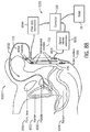
- FIG. 1 is a partial perspective view of a room in which a medical procedure is taking place by using a surgical robot, the movement of which is controlled by analysis of RF signals that are emitted from an inside the patient and received by RF receivers mounted therein.
- FIG. 2 is a perspective view of a surgical robot according to an embodiment of the invention.
- FIGS. 3A-3B are perspective views of the surgical robot illustrated in FIG. 2 , which show the movement of the base of the surgical robot in the z-axis direction in accordance with an embodiment of the invention.
- FIG. 4 is a partial perspective view of the surgical robot of FIG. 2 which shows how the robot arm can be moved in the x-axis direction.
- FIGS. 5A-5B are partial perspective views of the surgical robot of FIG. 2 , which show how the robot arm can be moved in the y-axis direction.
- FIG. 6 is a perspective view of a portion of the robot arm of FIG. 2 showing how an effectuator element can be twisted about a y-axis.
- FIG. 7 is a perspective view of a portion of a robot arm of FIG. 2 showing how an effectuator element can be pivoted about a pivot axis that is perpendicular to the y-axis.
- FIGS. 8A-8B are partial perspective views of the surgical robot of FIG. 2 , which show the movement of a surgical instrument 35 along the z-axis from an effectuator element.
- FIG. 9 is a system diagram which shows local positioning sensors, a controlling PC, and a Radiofrequency (RF) transmitter in accordance with an embodiment of the invention.
- RF Radiofrequency
- FIG. 10 is a system diagram of the controlling PC, user input, and motors for controlling the robot in accordance with an embodiment of the invention.
- FIG. 11 is a flow chart diagram for general operation of a surgical robot in accordance with one embodiment of the invention.
- FIG. 12 is a flow chart diagram for a closed screw/needle insertion performed using a surgical robot in accordance with one embodiment of the invention.
- FIG. 13 is a flow chart diagram of a safe zone surgery performed using a surgical robot as described herein in accordance with one embodiment of the invention.
- FIG. 14 is a flow chart diagram of a flexible catheter insertion procedure performed using a surgical robot as described herein in accordance with one embodiment of the invention.
- FIG. 15A shows a screenshot of a monitor display showing a set up of the anatomy in X, Y and Z views in accordance with one embodiment of the invention.
- FIG. 15B shows a screenshot of a monitor display showing what the user views during an invasive procedure in accordance with one embodiment of the invention.
- FIG. 16 depicts a surgical robot having a plurality of optical markers mounted for tracking movement in an x-direction in accordance with one embodiment of the invention.
- FIGS. 17A-17B depict surgical instruments having a stop mechanism in accordance with one embodiment of the invention.
- FIGS. 17C-17E illustrate tools for manually adjusting a drill stop with reference to drill bit markings in accordance with one embodiment of the invention.
- FIGS. 17F-J illustrate tools for locking and holding a drill bit in a set position in accordance with one embodiment of the invention.
- FIGS. 18A-18B depicts an end-effectuator having a clearance mechanism in accordance with one embodiment of the invention.
- FIG. 19A-19B depicts an end-effectuator having an attachment element for applying distraction and/or compression forces in accordance with one embodiment of the invention.
- FIGS. 20A-20E show the use of calibration frames with the guidance system in accordance with one embodiment of the invention.
- FIG. 21A depicts flexible roll configurations of a targeting fixture in accordance with one embodiment of the invention.
- FIG. 21B shows possible positions of markers along a line in space in accordance with one embodiment of the invention.
- FIG. 21C depicts flexible roll configurations of a targeting fixture in accordance with one embodiment of the invention.
- FIG. 21D shows a fixture that can be employed to provide desired stiffness to the unrolled fixture such that it maintains its position after unrolling occurs in accordance with one embodiment of the invention.
- FIGS. 22A-22D depict a targeting fixture and method configured for application to the skull of a patient in accordance with one embodiment of the invention.
- FIG. 23 depicts a dynamic tracking device mounted to the spinous process of the lumbar spine of a patient in accordance with one embodiment of the invention.
- FIGS. 24-33 illustrate methods in accordance with one embodiment of the invention.
- FIG. 34 illustrates a computing platform that enables implementation of various embodiments of the invention.
- FIGS. 35A-35B display a surgical robot in accordance with one embodiment of the invention.
- FIG. 36 illustrates a surgical robot system having a surveillance marker in accordance with one or more embodiments described herein.
- FIG. 37 illustrates an example of a methodology for tracking a visual point on a rigid body using an array of three attached markers in accordance with one embodiment of the invention.
- FIG. 38 illustrates a procedure for monitoring the location of a point of interest relative to three markers based on images received form the methodology illustrated in FIG. 37 .
- FIGS. 39A-F illustrates examples of tracking methodology based on an array of three attached markers in accordance with one embodiment of the invention.
- FIG. 40 illustrates an example of a two dimensional representation for rotation about the Y-axis in accordance with one embodiment of the invention.
- FIG. 41A illustrates an alternative representation of a two dimensional representation for rotation about an X-axis in accordance with one embodiment of the invention.
- FIG. 41B illustrates an alternative representation of a two dimensional representation for rotation about a Y-axis in accordance with one embodiment of the invention.
- FIG. 41C illustrates an alternative representation of a two dimensional representation for rotation about a Z-axis in accordance with one embodiment of the invention.
- FIG. 42 provides a depiction of a noise within a frame of data.
- FIG. 43 illustrates the depiction of a noise within a frame of data as shown in FIG. 42 with a stored point of interest.
- FIG. 44 illustrates a depiction of results of applying a least squares fitting algorithm for establishing a reference frame and transforming markers in accordance with one embodiment of the invention.
- FIG. 45 illustrates a depiction of results of applying a least squares fitting algorithm for establishing a reference frame and transforming markers as shown in FIG. 44 including noise.
- FIG. 46 illustrates a depiction of error calculation for reference frame markers in accordance with one embodiment of the invention.
- FIG. 47 illustrates a graphical representation of methods of tracking three dimensional movement of a rigid body.
- FIG. 48 shows a perspective view illustrating a bayonet mount used to removably couple the surgical instrument to the end-effectuator in accordance with one embodiment of the invention.
- FIGS. 49A-49F depict illustrations of targeting fixtures in accordance with one embodiment of the invention.
- FIG. 50A shows an example illustration of one portion of a spine with markers in accordance with one embodiment of the invention.
- FIGS. 50B-50D show various illustrations of one portion of a spine with two independent trackers with markers in accordance with one embodiment of the invention.
- FIG. 50E illustrates a representation of a display of a portion of a spine based on the location of a tracker in accordance with one embodiment of the invention.
- FIG. 50F illustrates a representation of a display of a portion of a spine based on the location of a tracker in accordance with one embodiment of the invention.
- FIGS. 50G-50H represent images of segmented CT scans in accordance with one embodiment of the invention.
- FIG. 51 shows an example of a fixture for use with fluoroscopic views in accordance with one embodiment of the invention.
- FIGS. 52A-52B illustrates expected images on anteroposterior and lateral x-rays of the spine with a misaligned fluoroscopy (x-ray) machine in accordance with one embodiment of the invention.
- FIGS. 53A-53B illustrates expected images on anteroposterior and lateral x-rays of the spine with a well aligned fluoroscopy (x-ray) machine in accordance with one embodiment of the invention.
- FIGS. 54A-54B illustrates expected images on anteroposterior and lateral x-rays of the spine with a well aligned fluoroscopy (x-ray) machine including overlaid computer-generated graphical images showing the planned trajectory and the current actual position of the robot end-effectuator in accordance with one embodiment of the invention.
- x-ray fluoroscopy
- FIGS. 55A-55B illustrates expected images on anteroposterior and lateral x-rays of the spine with a well aligned fluoroscopy (x-ray) machine showing a feature on the targeting fixture designed to eliminate ambiguity about directionality in accordance with one embodiment of the invention.
- x-ray fluoroscopy
- FIG. 56 illustrates an axial view of a spine showing how a cartoonish axial approximation of the spine can be constructed based on lateral and anteroposterior x-rays in accordance with one embodiment of the invention.
- FIGS. 57A-57B illustrates examples of targeting fixtures that facilitate desired alignment of the targeting fixture relative to the x-ray image plane in accordance with one embodiment of the invention.
- FIGS. 58A-58B illustrates expected images on anteroposterior and lateral x-rays of the spine with a well aligned fluoroscopy (x-ray) machine when parallax is present in accordance with one embodiment of the invention.
- FIG. 59A illustrates two parallel plates with identically positioned radio-opaque markers in accordance with one embodiment of the invention.
- FIG. 59B illustrates resulting expected x-ray demonstrating how marker overlay is affected due to parallax using the two parallel plates as shown in FIG. 59A in accordance with one embodiment of the invention.
- FIG. 60 shows a representation of the rendering of a computer screen with an x-ray image that is affected by parallax overlaid by graphical markers over the radio-opaque markers on two plates that have the same geometry in accordance with one embodiment of the invention.
- FIG. 61 shows a graphical overlay for the x-ray image screen intended to help the user physically line up the x-ray machine to get a view in which the markers on the two calibration plates shown in FIG. 59A in the case where parallax complicates the view in accordance with one embodiment of the invention.
- FIG. 62 illustrates a method in accordance with at least one embodiment of the invention.
- FIGS. 63A-63C illustrates various embodiments of an end-effectuator including a modified mount with a clamping piece in accordance with at least one embodiment of the invention.
- FIGS. 64-65 illustrate embodiments of clamping piece actuation on a spinous process in accordance with some embodiments of the invention.
- FIG. 66A illustrates a clamping piece modified with a targeting fixture including a temporary marker skirt in accordance with at least one embodiment of the invention.
- FIG. 66B illustrates a clamping piece modified with a targeting fixture as shown in FIG. 66A with the temporary marker skirt detached in accordance with at least one embodiment of the invention.
- FIG. 67 shows a modified Mayfield frame 6700 including one possible configuration for active and radio-opaque markers in accordance with one embodiment of the invention.
- FIG. 68 shows end-effectuator 30 that includes nested dilators in accordance with at least one embodiment of the invention.
- FIGS. 69A-69C illustrates various embodiments of an end-effectuator including cylindrical dilator tubes in accordance with at least one embodiment of the invention.
- FIG. 70 illustrates a method in accordance with at least one embodiment of the invention.
- FIG. 71A illustrates a robot end-effectuator coupled with a curved guide tube for use with a curved or straight wire or tool in accordance with at least one embodiment of the invention.
- FIG. 71B illustrates a robot end-effectuator coupled with a straight guide tube for use with a curved or straight wire or tool in accordance with at least one embodiment of the invention.
- FIG. 72 illustrates a guide tube in accordance with at least one embodiment of the invention.
- FIG. 73 illustrates a steerable and trackable needle in accordance with at least one embodiment of the invention.
- FIG. 74 illustrates one embodiment of intersecting and interlocking bone screws in accordance with at least one embodiment of the invention.
- FIG. 75A-75B illustrates configurations of a robot for positioning alongside a bed of a patient that includes a targeting fixture coupled to an end-effectuator using a snap-in post.
- FIG. 76 illustrates a surgical robot having a plurality of optical markers mounted for calibration and tracking movement in accordance with one embodiment of the invention.
- FIG. 77 illustrates a CT scan and methods in accordance with one embodiment of the invention.
- FIG. 78 illustrates a biopsy tool in accordance with one embodiment of the invention.
- FIG. 79 illustrates a deep brain stimulation electrode placement method performed by the robot system in accordance with one embodiment of the invention.
- FIG. 80 illustrates a partial view of a surgical robot system including a visual indicator comprising lights projected on the surgical field in accordance with one embodiment of the invention.
- FIG. 81 illustrates a perspective view of a robot system including a camera arm in accordance with one embodiment of the invention.
- FIG. 82A illustrates a front-side perspective view of a robot system including a camera arm in a stored position in accordance with one embodiment of the invention.
- FIG. 82B illustrates a rear-side perspective view of a robot system including a camera arm in a stored position in accordance with one embodiment of the invention.
- FIG. 83 shows a lateral illustration of a patient lying supine, showing the normal relative positions of the prostate, rectum, bladder, and pubic bone.
- FIG. 84A shows a lateral illustration of a patient lying supine, showing how inflation of a balloon can cause anterior displacement of the prostate toward the pubic bone, and a controllable amount of compression against the pubic bone in accordance with one embodiment of the invention.
- FIG. 84B shows a lateral illustration of a patient lying supine, showing how shifting of a paddle in the rectum can cause anterior displacement of the prostate toward the pubic bone, and a controllable amount of compression against the pubic bone in accordance with one embodiment of the invention.
- FIG. 85 shows a sketch of a targeting fixture and immobilization device to be used for tracking the prostate during image-guided surgical procedures in accordance with one embodiment of the invention.
- FIG. 86 shows an illustration of the device as illustrated in FIG. 85 , in place in the rectum with prostate compressed and immobilized and tracking markers visible protruding caudal to the rectum in accordance with one embodiment of the invention.
- FIG. 87 illustrates a demonstration of a fibre Bragg grating (“FBG”) interrogation technology with a flexible fiber optic cable in accordance with one embodiment of the invention.
- FBG fibre Bragg grating
- FIG. 88 illustrates a tracker attached to the surface of the skin of a patient and rigidly interconnected to a fiber optic probe to allow accurate tracking of the prostate in accordance with one embodiment of the invention.
- FIG. 89 illustrates the fiber optic probe as depicted in FIG. 88 with optically visible and MRI visible markings in accordance with one embodiment of the invention.
- FIGS. 90-93 illustrate various embodiments of a fiber optic probe tracking system to allow accurate tracking of the prostate for image-guided therapy in accordance with one embodiment of the invention.
- FIG. 94 illustrates one embodiment of a nerve sensing probe.
- a delivery conduit can include two or more such delivery conduits unless the context indicates otherwise.
- the terms “optional” or “optionally” mean that the subsequently described event or circumstance may or may not occur, and that the description includes instances where said event or circumstance occurs and instances where it does not.
- the disclosed devices and systems can comprise elements of the devices and systems described in U.S. Patent Publication Nos. 2007/0238985, 2008/0154389, and 2008/0215181, the disclosures of which are incorporated herein by reference in their entireties.
- a unit may be, but is not limited to being, a process running on a processor, a processor, an object, an executable computer program, a thread of execution, a program, a memory (e.g., a hard disc drive), and/or a computer.
- a unit can be an apparatus with specific functionality provided by mechanical parts operated by electric or electronic circuitry which is operated by a software application or a firmware application executed by a processor, wherein the processor can be internal or external to the apparatus and executes at least a part of the software or firmware application.
- a unit can provide specific functionality based on physical structure or specific arrangement of hardware elements.
- a unit can be an apparatus that provides specific functionality through electronic functional elements without mechanical parts, the electronic functional elements can include a processor therein to execute software or firmware that provides at least in part the functionality of the electronic functional elements.
- An illustration of such apparatus can be control circuitry, such as a programmable logic controller.
- the surgical robot system 1 can comprise a surgical robot 15 and one or more positioning sensors 12 .
- the surgical robot 15 can comprise a display means 29 (including for example a display 150 shown in FIG. 10 ), and a housing 27 .
- a display 150 can be attached to the surgical robot 15
- a display means 29 can be detached from surgical robot 15 , either within surgical room 10 or in a remote location.
- the housing 27 can comprise a robot arm 23 , and an end-effectuator 30 coupled to the robot arm 23 controlled by at least one motor 160 .
- the surgical robot system 1 can include a motor assembly 155 comprising at least one motor (represented as 160 in FIG. 10 ).
- the end-effectuator 30 can comprise a surgical instrument 35 .
- the end-effectuator 30 can be coupled to the surgical instrument 35 .
- the term “end-effectuator” is used interchangeably with the terms “end-effectuator,” “effectuator element,” and “effectuator element.”
- the end-effectuator 30 can comprise any known structure for effecting the movement of the surgical instrument 35 in a desired manner.
- a three-dimensional (“3D”) image scan can be taken of a desired surgical area of the patient 18 and sent to a computer platform in communication with surgical robot 15 as described herein (see for example the platform 3400 including the computing device 3401 shown in FIG. 34 ).
- a physician can then program a desired point of insertion and trajectory for surgical instrument 35 to reach a desired anatomical target within or upon the body of patient 18 .
- the desired point of insertion and trajectory can be planned on the 3D image scan, which in some embodiments, can be displayed on display means 29 .
- a physician can plan the trajectory and desired insertion point (if any) on a computed tomography scan (hereinafter referred to as “CT scan”) of a patient 18 .
- CT scan computed tomography scan
- the CT scan can be an isocentric C-arm type scan, an O-arm type scan, or intraoperative CT scan as is known in the art.
- any known 3D image scan can be used in accordance with the embodiments of the invention described herein.
- the surgical robot system 1 can comprise a local positioning system (“LPS”) subassembly to track the position of surgical instrument 35 .
- the LPS subassembly can comprise at least one radio-frequency (RF) transmitter 120 that is coupled were affixed to the end-effectuator 30 or the surgical instrument 35 at a desired location.
- the at least one RF transmitter 120 can comprise a plurality of transmitters 120 , such as, for example, at least three RF transmitters 120 .
- the LPS subassembly can comprise at least one RF receiver 110 configured to receive one or more RF signals produced by the at least one RF transmitter 120 .
- the at least one RF receiver 110 can comprise a plurality of RF receivers 110 , such as, for example, at least three RF receivers 110 .
- the RF receivers 110 can be positioned at known locations within the room 10 where the medical procedure is to take place.
- the RF receivers 110 can be positioned at known locations within the room 10 such that the RF receivers 110 are not coplanar within a plane that is parallel to the floor of the room 10 .
- the time of flight of an RF signal from each RF transmitter 120 of the at least one RF transmitter 120 to each RF receiver 110 of the at least one RF receiver 110 can be measured to calculate the position of each RF transmitter 120 . Because the velocity of the RF signal is known, the time of flight measurements result in at least three distance measurements for each RF transmitter 120 (one to each RF receiver 110 ).
- the surgical robot system 1 can comprise a control device (for example a computer 100 having a processor and a memory coupled to the processor).
- the processor of the control device 100 can be configured to perform time of flight calculations as described herein.
- the processor of the control device 100 can be configured to provide a geometrical description of the location of the at least one RF transmitter 120 with respect to an operative end of the surgical instrument 35 or end-effectuator 30 that is utilized to perform or assist in performing an invasive procedure.
- the position of the RF transmitter 120 , as well as the dimensional profile of the surgical instrument 35 or the effectuator element 30 can be displayed on a monitor (for example on a display means 29 such as the display 150 shown in FIG. 10 ).
- the end-effectuator 30 can be a tubular element (for example a guide tube 50 ) that is positioned at a desired location with respect to, for example, a patient's 18 spine to facilitate the performance of a spinal surgery.
- the guide tube 50 can be aligned with the z axis 70 defined by a corresponding robot motor 160 or, for example, can be disposed at a selected angle relative to the z-axis 70 .
- the processor of the control device i.e. the computer 100
- the memory of the control device (computer 100 for example) can store software for performing the calculations and/or analyses required to perform many of the surgical method steps set forth herein.
- Another embodiment of the disclosed surgical robot system 1 involves the utilization of a robot 15 that is capable of moving the end-effectuator 30 along x-, y-, and z-axes (see 66 , 68 , 70 in FIG. 35B ).
- the x-axis 66 can be orthogonal to the y-axis 68 and z-axis 70
- the y-axis 68 can be orthogonal to the x-axis 66 and z-axis 70
- the z-axis 70 can be orthogonal to the x-axis 66 and the y-axis 68 .
- the robot 15 can be configured to effect movement of the end-effectuator 30 along one axis independently of the other axes. For example, in some embodiments, the robot 15 can cause the end-effectuator 30 to move a given distance along the x-axis 66 without causing any significant movement of the end-effectuator 30 along the y-axis 68 or z-axis 70 .
- the end-effectuator 30 can be configured for selective rotation about one or more of the x-axis 66 , y-axis 68 , and z-axis 70 (such that one or more of the Cardanic Euler Angles (e.g., roll, pitch, and/or yaw) associated with the end-effectuator 30 can be selectively controlled).
- the end-effectuator 30 and/or surgical instrument 35 can be aligned with a selected orientation axis (labeled “Z Tube” in FIG. 35B ) that can be selectively varied and monitored by an agent (for example computer 100 and platform 3400 ) that can operate the surgical robot system 1 .
- selective control of the axial rotation and orientation of the end-effectuator 30 can permit performance of medical procedures with significantly improved accuracy compared to conventional robots that utilize, for example, a six degree of freedom robot arm 23 comprising only rotational axes.
- the robot arm 23 that can be positioned above the body of the patient 18 , with the end-effectuator 30 selectively angled relative to the z-axis toward the body of the patient 18 .
- the robotic surgical system 1 can comprise systems for stabilizing the robotic arm 23 , the end-effectuator 30 , and/or the surgical instrument 35 at their respective positions in the event of power failure.
- the robotic arm 23 , end-effectuator 30 , and/or surgical instrument 35 can comprise a conventional worm-drive mechanism (not shown) coupled to the robotic arm 23 , configured to effect movement of the robotic arm along the z-axis 70 .
- the system for stabilizing the robotic arm 23 , end-effectuator 30 , and/or surgical instrument 35 can comprise a counterbalance coupled to the robotic arm 23 .
- the means for maintaining the robotic arm 23 , end-effectuator 30 , and/or surgical instrument 35 can comprise a conventional brake mechanism (not shown) that is coupled to at least a portion of the robotic arm 23 , such as, for example, the end-effectuator 30 , and that is configured for activation in response to a loss of power or “power off” condition of the surgical robot 15 .
- the surgical robot system 1 can comprise a plurality of positioning sensors 12 configured to receive RF signals from the at least one conventional RF transmitter (not shown) located within room 10 .
- the at least one RF transmitter 120 can be disposed on various points on the surgical robot 15 and/or on patient 18 .
- the at least one RF transmitter 120 can be attached to one or more of the housing 27 , robot arm 23 , end-effectuator 30 , and surgical instrument 35 .
- Some embodiments include positioning sensors 12 that in some embodiments comprise RF receivers 110 .
- RF receivers 110 are in communication with a computer platform as described herein (see for example 3400 comprising a computing device 3401 FIG.
- each transmitter 120 of the at least one RF transmitter 120 can transmit RF energy on a different frequency so that the identity of each transmitter 120 in the room 10 can be determined.
- the location of the at least one RF transmitter 120 , and, consequently, the objects to which the transmitters 120 are attached, are calculated by the computer (e.g., computing device 3401 in FIG. 34 ) using time-of-flight processes.
- the computer (not shown in FIG. 1 ) is also in communication with surgical robot 15 .
- a conventional processor (not shown) of the computer 100 of the computing device 3401 can be configured to effect movement of the surgical robot 15 according to a preplanned trajectory selected prior to the procedure.
- the computer 100 of the computing device 3401 can use robotic guidance software 3406 and robotic guidance data storage 3407 (shown in FIG. 34 ) to effect movement of the surgical robot 15 .
- the position of surgical instrument 35 can be dynamically updated so that surgical robot 15 is aware of the location of surgical instrument 35 at all times during the procedure. Consequently, in some embodiments, the surgical robot 15 can move the surgical instrument 35 to the desired position quickly, with minimal damage to patient 18 , and without any further assistance from a physician (unless the physician so desires). In some further embodiments, the surgical robot 15 can be configured to correct the path of surgical instrument 35 if the surgical instrument 35 strays from the selected, preplanned trajectory.
- the surgical robot 15 can be configured to permit stoppage, modification, and/or manual control of the movement of the end-effectuator 30 and/or surgical instrument 35 .
- an agent e.g., a physician or other user
- tolerance controls can be preprogrammed into the surgical robot 15 and/or processor of the computer platform 3400 (such that the movement of the end-effectuator 30 and/or surgical instrument 35 is adjusted in response to specified conditions being met).
- the surgical robot 15 can be configured to stop movement of end-effectuator 30 and/or surgical instrument 35 .
- the surgical robot 15 detects a resistance, such as a force resistance or a torque resistance above a tolerance level, then the surgical robot 15 can be configured to stop movement of end-effectuator 30 and/or surgical instrument 35 .
- the computer 100 for use in the system can be located within surgical robot 15 , or, alternatively, in another location within surgical room 10 or in a remote location. In some embodiments, the computer 100 can be positioned in operative communication with positioning sensors 12 and surgical robot 15 .
- the surgical robot 15 can also be used with existing conventional guidance systems.
- alternative conventional guidance systems beyond those specifically disclosed herein are within the scope and spirit of the invention.
- a conventional optical tracking system 3417 for tracking the location of the surgical device or a commercially available infrared optical tracking system 3417 , such as Optotrak® (Optotrak® is a registered trademark of Northern Digital Inc. Northern Digital, Waterloo, Ontario, Canada), can be used to track the patient 18 movement and the robot's base 25 location and/or intermediate axis location, and used with the surgical robot system 1 .
- Optotrak® is a registered trademark of Northern Digital Inc. Northern Digital, Waterloo, Ontario, Canada
- the surgical robot system 1 can comprise conventional optical markers attached to selected locations on the end-effectuator 30 and/or the surgical instrument 35 that are configured to emit or reflect light.
- the light emitted from and/or reflected by the markers can be read by cameras (for example with cameras 8200 shown in FIG. 81 ) and/or optical sensors and the location of the object can be calculated through triangulation methods (such as stereo-photogrammetry).
- the surgical robot 15 can comprise a base 25 connected to wheels 31 .
- the size and mobility of these embodiments can enable the surgical robot to be readily moved from patient to patient and room to room as desired.
- the surgical robot 15 can further comprise a case 40 that is slidably attached to base 25 such that the case 40 can slide up and down along the z-axis 70 substantially perpendicular to the surface on which base 25 sits.
- the surgical robot 15 can include a display means 29 , and a housing 27 which contains robot arm 23 .
- the end-effectuator 30 can comprise a surgical instrument 35 , whereas in other embodiments, the end-effectuator 30 can be coupled to the surgical instrument 35 . In some embodiments, it is arm 23 can be connected to the end-effectuator 30 , with surgical instrument 35 being removably attached to the end-effectuator 30 .
- the effectuator element 30 can include an outer surface 30 d , and can comprise a distal end 30 a defining a beveled leading edge 30 b and a non-beveled leading edge 30 c .
- the surgical instrument 35 can be any known conventional instrument, device, hardware component, and/or attachment that is used during performance of an invasive or non-invasive medical procedure (including surgical, therapeutic, and diagnostic procedures).
- the surgical instrument 35 can be embodied in or can comprise a needle 7405 , 7410 , a conventional probe, a conventional screw, a conventional drill, a conventional tap, a conventional catheter, a conventional scalpel forceps, or the like.
- the surgical instrument 35 can be a biological delivery device, such as, for example and without limitation, a conventional syringe, which can distribute biologically acting compounds throughout the body of a patient 18 .
- the surgical instrument 35 can comprise a guide tube 50 (also referred to herein as a “Z-tube 50 ”) that defines a central bore configured for receipt of one or more additional surgical instruments 35 .
- the surgical robot 15 is moveable in a plurality of axes (for instance x-axis 66 , y-axis 68 , and z-axis 70 ) in order to improve the ability to accurately and precisely reach a target location.
- Some embodiments include a robot 15 that moves on a Cartesian positioning system; that is, movements in different axes can occur relatively independently of one another instead of at the end of a series of joints.
- case 40 can be configured to be raised and lowered relative to the base 25 along the z-axis.
- Some embodiments include a housing 27 that can be attached to case 40 and be configured to move in the z-direction (defined by z-frame 72 ) with case 40 when case 40 is raised and lowered. Consequently, in some embodiments, arm 23 , the end-effectuator 30 , and surgical instrument 35 can be configured to move with case 40 as case 40 is raised and lowered relative to base 25 .
- housing 27 can be slidably attached to case 40 so that it can extend and retract along the x-axis 66 relative to case 40 and substantially perpendicularly to the direction case 40 moves relative to base 25 . Consequently, in some embodiments, the robot arm 23 , the end-effectuator 30 , and surgical instrument 35 can be configured to move with housing 27 as housing 27 is extended and retracted relative to case 40 .
- robot arm 23 can be extendable along the y-axis 68 relative to case 40 , base 25 , and housing 27 . Consequently, in some embodiments, the end-effectuator 30 and surgical instrument 35 can be configured to move with arm 23 as arm 23 is extended and retracted relative to housing 27 .
- arm 23 can be attached to a low profile rail system (not shown) which is encased by housing 27 .
- FIG. 6 shows an embodiment of an end-effectuator 30 that is configured to rotate about the y-axis 68 , performing a rotation having a specific roll 62 .
- FIG. 7 shows an embodiment of an end-effectuator 30 that is configured to rotate about the x-axis 66 , performing a rotation having a specific pitch 60 .
- FIG. 8 shows an embodiment of an end-effectuator 30 that is configured to raise and lower surgical instrument 35 along a substantially vertical axis, which can be a secondary movable axis 64 , referred to as “Z-tube axis 64 ”.
- the orientation of the guide tube 50 can be initially aligned with z-axis 70 , but such orientation can change in response to changes in roll 62 and/or pitch 60 .
- FIG. 9 shows a system diagram of the 3D positioning sensors 110 , computer 100 , and RF transmitters 120 in accordance with some embodiments of the invention is provided.
- computer 100 is in communication with positioning sensors 110 .
- RF transmitters 120 are attached to various points on the surgical robot 15 .
- the RF transmitters 120 can also be attached to various points on or around an anatomical target of a patient 18 .
- computer 100 can be configured to send a signal to the RF transmitters 120 , prompting the RF transmitters 120 to transmit RF signals that are read by the positioning sensors 110 .
- the computer 100 can be coupled to the RF transmitters 120 using any conventional communication means, whether wired or wireless.
- the positioning sensors 110 can be in communication with computer 100 , which can be configured to calculate the location of the positions of all the RF transmitters 120 based on time-of-flight information received from the positioning sensors 110 .
- computer 100 can be configured to dynamically update the calculated location of the surgical instrument 35 and/or end-effectuator 30 being used in the procedure, which can be displayed to the agent.
- Some embodiments can include a system diagram of surgical robot system 1 having a computer 100 , a display means 29 comprising a display 150 , user input 170 , and motors 160 , provided as illustrated in FIG. 10 .
- motors 160 can be installed in the surgical robot 15 and control the movement of the end-effectuator 30 and/or surgical instrument 35 as described above.
- computer 100 can be configured to dynamically update the location of the surgical instrument 35 being used in the procedure, and can be configured to send appropriate signals to the motors 160 such that the surgical robot 15 has a corresponding response to the information received by computer 100 .
- the computer 100 in response to information received by computer 100 , the computer 100 can be configured to prompt the motors 160 to move the surgical instrument 35 along a preplanned trajectory.
- user input 170 can be used to plan the trajectory for a desired navigation.
- a user can use the user input 170 to input the desired changes, and the computer 100 can be configured to transmit corresponding signals to the motors 160 in response to the user input 170 .
- the motors 160 can be or can comprise conventional pulse motors.
- the pulse motors can be in a conventional direct drive configuration or a belt drive and pulley combination attached to the surgical instrument 35 .
- the motors 160 can be conventional pulse motors that are attached to a conventional belt drive rack-and-pinion system or equivalent conventional power transmission component.
- the use of conventional linear pulse motors within the surgical robot 15 can permit establishment of a non-rigid position for the end-effectuator 30 and/or surgical instrument 35 .
- the end-effectuator 30 and/or surgical instrument 35 will not be fixed in a completely rigid position, but rather the end-effectuator 30 and/or the surgical instrument 35 can be configured such that an agent (e.g., a surgeon or other user) can overcome the x-axis 66 and y-axis 68 , and force the end-effectuator 30 and/or surgical instrument 35 from its current position.
- an agent e.g., a surgeon or other user
- the amount of force necessary to overcome such axes can be adjusted and configured automatically or by an agent.
- the surgical robot 15 can comprise circuitry configured to monitor one or more of: (a) the position of the robot arm 23 , the end-effectuator 30 , and/or the surgical instrument 35 along the x-axis 66 , y-axis 68 , and z-axis 70 ; (b) the rotational position (e.g., roll 62 and pitch 60 ) of the robot arm 23 , the end-effectuator 30 , and/or the surgical instrument 35 relative to the x-( 66 ), y-( 68 ), and z-( 70 ) axes; and (c) the position of the end-effectuator 30 , and/or the surgical instrument 35 along the travel of the re-orientable axis that is parallel at all times to the end-effectuator 30 and surgical instrument 35 (the Z-tube axis 64 ).
- the rotational position e.g., roll 62 and pitch 60
- circuitry for monitoring the positions of the x-axis 66 , y-axis 68 , z-axis 70 , Z-tube axis 64 , roll 62 , and/or pitch 60 can comprise relative or absolute conventional encoder units (also referred to as encoders) embedded within or functionally coupled to conventional actuators and/or bearings of at least one of the motors 160 .
- the circuitry of the surgical robot 15 can be configured to provide auditory, visual, and/or tactile feedback to the surgeon or other user when the desired amount of positional tolerance (e.g., rotational tolerance, translational tolerance, a combination thereof, or the like) for the trajectory has been exceeded.
- the positional tolerance can be configurable and defined, for example, in units of degrees and/or millimeters.
- the robot 15 moves into a selected position, ready for the surgeon to deliver a selected surgical instrument 35 , such as, for example and without limitation, a conventional screw, a biopsy needle 8110 , and the like.
- a selected surgical instrument 35 such as, for example and without limitation, a conventional screw, a biopsy needle 8110 , and the like.
- the system 1 can be configured to provide an audible warning and/or a visual warning.
- the system 1 can produce audible beeps and/or display a warning message on the display means 29 , such as “Warning: Off Trajectory,” while also displaying the axes for which an acceptable tolerance has been exceeded.
- a light illumination may be directed to the end-effectuator 30 , the guide tube 50 , the operation area (i.e. the surgical field 17 ) of the patient 18 , or a combination of these regions.
- some embodiments include at least one visual indication 900 capable of illuminating a surgical field 17 of a patient 18 .
- Some embodiments include at least one visual indication 900 capable of indicating a target lock by projecting an illumination on a surgical field 17 .
- the system 1 can provide feedback to the user regarding whether the robot 15 is locked on target.
- the system 1 can provide an alert to the user regarding whether at least one marker 720 is blocked, or whether the system 1 is actively seeking one or more markers 720 .
- the visual indication 900 can be projected by one or more conventional light emitting diodes mounted on or near the robot end-effectuator 30 .
- the visual indication can comprise lights projected on the surgical field 17 including a color indicative of the current situation (see for example, FIG. 80 ).
- a green projected light could represent a locked-on-target situation
- a red illumination could indicate a trajectory error, or obscured markers 720 .
- a yellow illumination could indicate the system 1 is actively seeking one or more markers 720 .
- the robot 15 can be configured to provide mechanical resistance (“push back” or haptic feedback) to the movement of the end-effectuator 30 and/or surgical instrument 35 in this manner, thereby promoting movement of the end-effectuator 30 and/or surgical instrument 35 back to the correct, selected orientation.
- the robot 15 can be configured to substantially immediately return the end-effectuator 30 and/or surgical instrument 35 back to the desired trajectory, at which time the audible and visual warnings and alerts can be configured to cease.
- the visual warning could include a visual indication 900 that may include a green light if no tolerances have been exceeded, or a red light if tolerances are about to, or have been exceeded.
- a conventional worm-drive system would be absolutely rigid, and a robot 15 having such a worm-drive system would be unable to be passively moved (without breaking the robot 15 ) no matter how hard the surgeon pushed.
- a completely rigid articulation system can be inherently unsafe to a patient 18 .
- a robot 15 were moving toward the patient 18 and inadvertently collided with tissues, then these tissues could be damaged.
- conventional sensors can be placed on the surface of such a robot 15 to compensate for these risks, such sensors can add considerable complexity to the overall system 1 and would be difficult to operate in a fail-safe mode.
- the end-effectuator 30 and/or surgical instrument 35 inadvertently collides with tissues of the patient 18 , a collision would occur with a more tolerable force that would be unlikely to damage such tissues.
- auditory and/or visual feedback as described above can be provided to indicate an increase in the current required to overcome the obstacle.
- the end-effectuator 30 of the robot 15 can be configured to displace itself (move away) from the inadvertently contacted tissue if a threshold required motor 160 current is encountered. In some embodiments, this threshold could be configured (by a control component, for example) for each axis such that the moderate forces associated with engagement between the tissue and the end-effectuator 30 can be recognized and/or avoided.
- the amount of rigidity associated with the positioning and orientation of the end-effectuator 30 and/or the surgical instrument 35 can be selectively varied.
- the robot 15 can be configured to shift between a high-rigidity mode and a low-rigidity mode.
- the robot 15 can be programmed so that it automatically shifts to the low-rigidity mode as the end-effectuator 30 and surgical instrument 35 are shifted from one trajectory to another, from a starting position as they approach a target trajectory and/or target position.
- the robot 15 can be configured to shift to the high-rigidity mode. In some embodiments, this mechanism may improve safety because the robot 15 would be unlikely to cause injury if it inadvertently collided with the patient 18 while in the low-rigidity mode.
- Some embodiments include a robot 15 that can be configured to effect movement of the end-effectuator 30 and/or surgical instrument 35 in a selected sequence of distinct movements.
- the x-axis 66 , y-axis 68 , roll 62 , and 60 pitch 60 orientations are all changed simultaneously, and the speed of movement of the end-effectuator 30 can be increased. Consequently, because of the range of positions through which the end-effectuator 30 travels, the likelihood of a collision with the tissue of the patient 18 can also be increased.
- the robot 15 can be configured to effect movement of the end-effectuator 30 and/or surgical instrument 35 such that the position of the end-effectuator 30 and/or surgical instrument 35 within the x-axis 66 and the y-axis 68 are adjusted before the roll 62 and pitch 60 of the end-effectuator 30 and/or surgical instrument 35 are adjusted.
- the robot 15 can be configured to effect movement of the end-effectuator 30 and/or surgical instrument 35 so that the roll 62 and pitch 60 are shifted to 0°. The position of the end-effectuator 30 and/or surgical instrument 35 within the x-axis 66 and the y-axis 68 are adjusted, and then the roll 62 and pitch 60 of the end-effectuator 30 and/or surgical instrument 35 are adjusted.
- Some embodiments include a robot 15 that can be optionally configured to ensure that the end-effectuator 30 and/or surgical instrument 35 are moved vertically along the z-axis 70 (away from the patient 18 ) by a selected amount before a change in the position and/or trajectory of the end-effectuator 30 and/or surgical instrument 35 is affected.
- the robot 15 when an agent (for example, a surgeon or other user, or equipment) changes the trajectory of the end-effectuator 30 and/or surgical instrument 35 from a first trajectory to a second trajectory, the robot 15 can be configured to vertically displace the end-effectuator 30 and/or surgical instrument 35 from the body of the patient 18 along the z-axis 70 by the selected amount (while adjusting x-axis 66 and y-axis 68 configurations to remain on the first trajectory vector, for example), and then effecting the change in position and/or orientation of the end-effectuator 30 and/or surgical instrument 35 . This ensures that the end-effectuator 30 and/or surgical instrument 35 do not move laterally while embedded within the tissue of the patient 18 .
- an agent for example, a surgeon or other user, or equipment
- the robot 15 can be configured to produce a warning message that seeks confirmation from the agent (for example, a surgeon or other user, or equipment) that it is safe to proceed with a change in the trajectory of the end-effectuator 30 and/or surgical instrument 35 without first displacing the end-effectuator 30 and/or surgical instrument 35 along the z-axis.
- the agent for example, a surgeon or other user, or equipment
- At least one conventional force sensor can be coupled to the end-effectuator 30 and/or surgical instrument 35 such that the at least one force sensor receives forces applied along the orientation axis (Z-tube axis 64 ) to the surgical instrument 35 .
- the at least one force sensor can be configured to produce a digital signal.
- the digital signal can be indicative of the force that is applied in the direction of the Z-tube axis 64 to the surgical instrument 35 by the body of the patient 18 as the surgical instrument 35 advances into the tissue of the patient 18 .
- the at least one force sensor can be a small conventional uniaxial load cell based on a conventional strain gauge mechanism.
- the uniaxial load cell can be coupled to, for example, analog-to-digital filtering to supply a continuous digital data stream to the system 1 .
- the at least one force sensor can be configured to substantially continuously produce signals indicative of the force that is currently being applied to the surgical instrument 35 .
- the surgical instrument 35 can be advanced into the tissue of the patient 18 by lowering the z-axis 70 while the position of the end-effectuator 30 and/or surgical instrument 35 along the x-axis 66 and y-axes 68 is adjusted such that alignment with the selected trajectory vector is substantially maintained.
- the roll 62 and pitch 60 orientations can remain constant or self-adjust during movement of the x-( 66 ), y-( 68 ), and z-( 70 ) axes such that the surgical instrument 35 remains oriented along the selected trajectory vector.
- the position of the end-effectuator 30 along the z-axis 70 can be locked at a selected mid-range position (spaced a selected distance from the patient 18 ) as the surgical instrument 35 advances into the tissue of the patient 18 .
- the stiffness of the end-effectuator 30 and/or the surgical instrument 35 can be set at a selected level as further described herein.
- the stiffness of the Z-tube axis 64 position of the end-effectuator 30 and/or the surgical instrument 35 can be coupled to a conventional mechanical lock (not shown) configured to impart desired longitudinal stiffness characteristics to the end-effectuator 30 and/or surgical instrument 35 .
- the counterforce applied by the tissue of the patient 18 during penetration of the surgical instrument 35 can oppose the direction of advancement of the surgical instrument 35 such that the surgical instrument 35 cannot advance along the selected trajectory vector.
- the Z-tube axis 64 can be forced up and there can be no net advancement of the surgical instrument 35 .
- the at least one force sensor can permit an agent (for example, a surgeon or other user, or equipment) to determine, (based on sudden increase in the level of applied force monitored by the force sensor at the end-effectuator 30 and/or the surgical instrument 35 ), when the surgical instrument 35 has encountered a bone or other specific structure within the body of the patient 18 .
- an agent for example, a surgeon or other user, or equipment
- the orientation angle of the end-effectuator 30 and/or surgical instrument 35 and the x-axis 66 and y-axis 68 can be configured to align the Z-tube axis 64 with the desired trajectory vector at a fully retracted Z-tube position, while a z-axis 70 position is set in which the distal tip of the surgical instrument 35 is poised to enter tissue.
- the end-effectuator 30 can be positioned in a manner that the end-effectuator 30 can move, for example, exactly or substantially exactly down the trajectory vector if it were advanced only along guide tube 50 .
- advancing the Z-tube axis 64 can cause the guide tube 50 to enter into tissue, and an agent (a surgeon or other user, equipment, etc.) can monitor change in force from the load sensor. Advancement can continue until a sudden increase in applied force is detected at the time the surgical instrument 35 contacts bone.
- an agent a surgeon or other user, equipment, etc.
- the robot 15 can be configured to deactivate the one or more motors 160 that advance the Z-tube axis 64 such that the end-effectuator 30 and/or the surgical instrument 35 can move freely in the Z-tube axis 64 direction while the position of the end-effectuator 30 and/or the surgical instrument 35 continues to be monitored.
- the surgeon can then push the end-effectuator 30 down along the Z-tube axis 64 , (which coincides with the desired trajectory vector) by hand.
- the position of the surgical instrument 35 can be corrected by adjustment along the x-( 66 ) and/or y-( 68 ) axes and/or in the roll 62 and/or pitch 60 directions.
- the agent for example, a surgeon or other user, or equipment
- the surgical instrument 35 can manually force the surgical instrument 35 to advance until a tactile sense of the surgical instrument 35 contacts bone, or another known region of the body).
- the robotic surgical system 1 can comprise a plurality of conventional tracking markers 720 configured to track the movement of the robot arm 23 , the end-effectuator 30 , and/or the surgical instrument 35 in three dimensions. It should be appreciated that three dimensional positional information from tracking markers 720 can be used in conjunction with the one dimensional linear positional information from absolute or relative conventional linear encoders on each axis of the robot 15 to maintain a high degree of accuracy.
- the plurality of tracking markers 720 can be mounted (or otherwise secured) thereon an outer surface of the robot 15 , such as, for example and without limitation, on the base 25 of the robot 15 , or the robot arm 23 .
- the plurality of tracking markers 720 can be configured to track the movement of the robot 15 arm, the end-effectuator 30 , and/or the surgical instrument 35 .
- the computer 100 can utilize the tracking information to calculate the orientation and coordinates of the distal tip 30 a of the surgical instrument 35 based on encoder counts along the x-axis 66 , y-axis 68 , z-axis 70 , the Z-tube axis 64 , and the roll 62 and pitch 60 axes.
- the plurality of tracking markers 720 can be positioned on the base 25 of the robot 15 spaced from the surgical field 17 to reduce the likelihood of being obscured by the surgeon, surgical tools, or other parts of the robot 15 .
- At least one tracking marker 720 of the plurality of tracking markers 720 can be mounted or otherwise secured to the end-effectuator 30 .
- the positioning of one or more tracking markers 720 on the end-effectuator 30 can maximize the accuracy of the positional measurements by serving to check or verify the end-effectuator 30 position (calculated from the positional information from the markers on the base 25 of the robot 15 and the encoder counts of the x-( 66 ), y-( 68 ), roll 62 , pitch 60 , and Z-tube axes 64 ).
- At least one optical marker of the plurality of optical tracking markers 720 can be positioned on the robot 15 between the base 25 of the robot 15 and the end-effectuator 30 instead of, or in addition to, the markers 720 on the base 25 of the robot 15 , (see FIG. 16 ).
- the at least one tracking marker 720 can be mounted to a portion of the robot 15 that effects movement of the end-effectuator 30 and/or surgical instrument 35 along the x-axis to enable the tracking marker 720 to move along the x-axis 66 as the end-effectuator 30 and surgical instrument 35 move along the x-axis 66 (see FIG. 76 ).
- the placement of the tracking markers 720 in this way can reduce the likelihood of a surgeon blocking the tracking marker 720 from the cameras or detection device, or the tracking marker 720 becoming an obstruction to surgery.
- the tracking marker 720 because of the high accuracy in calculating the orientation and position of the end-effectuator 30 based on the tracking marker 720 outputs and/or encoder counts from each axis, it can be possible to very accurately determine the position of the end-effectuator 30 .
- the placement of markers 720 on any intermediate axis of the robot 15 can permit the exact position of the end-effectuator 30 to be calculated based on location of such markers 720 and counts of encoders on axes ( 66 , 62 , 60 , 64 ) between the markers 720 and the end-effectuator 30 .
- the order of axes from the base 25 to the end-effectuator 30 is z-( 70 ) then x-( 66 ) then y-( 68 ) then roll 62 then pitch 60 then Z-tube 64 .
- tracking markers 720 are placed on the housing 27 of the robot 15 that moves with the roll 62 axis, the locations of such tracking markers 720 and the encoder counts of the pitch 60 and Z-tube axes 64 can be sufficient to calculate the end-effectuator 30 position.
- the surgical instrument 35 when the surgical instrument 35 is advanced into the tissue of the patient 18 with the assistance of a guide tube 50 , the surgical instrument 35 can comprise a stop mechanism 52 that is configured to prevent the surgical instrument 35 from advancing when it reaches a predetermined amount of protrusion (see for example, FIGS. 17A-B ).
- a stop mechanism 52 that is configured to prevent the surgical instrument 35 from advancing when it reaches a predetermined amount of protrusion (see for example, FIGS. 17A-B ).
- the robot 15 can substantially continuously monitor the protrusion distance, and in some embodiments, the distance can be displayed on a display (such as display means 29 ).
- protrusion distance can be substantially continuously monitored using a spring-loaded plunger 54 including a spring-loaded mechanism 55 a and sensor pad 55 b that has a coupled wiper 56 (see for example FIG. 17B ).
- the stop mechanism 52 on the surgical instrument 35 can be configured to contact the spring-loaded mechanism 55 well before it encounters the end of the guide tube 50 .
- any conventional linear encoding mechanism can be used to monitor the plunger's depth of depression and transmit that information to the computer 100 as further described herein.
- FIGS. 17C-17E depict tools for manually adjusting a drill stop 46 with reference to drill bit markings 44 in accordance with one embodiment of the invention.
- the drill bit 42 can include release mechanisms 48 on each end of the drill stop 46 .
- the release 48 on one end of the drill stop 46 is pulled, it is possible to move the drill stop 46 up the shaft of the drill bit 42 .
- the release 48 on the other end of the drill stop 46 is pulled, it is possible to move the drill stop 46 down the shaft (see the direction of movement in FIGS. 17D and 17E ).
- neither release mechanism 48 is pulled, the drill stop 46 will not move in either direction, even if bumped.
- Some embodiments include the ability to lock and hold the drill bit 42 in a set position relative to the tube 50 in which it is housed.
- the drill bit 42 can be locked by locking the drill stop 46 relative to the tube 50 using a locking mechanism.
- FIGS. 17F-J illustrates tools for locking and holding a drill bit 42 in a set position in accordance with one embodiment of the invention.
- the locking mechanism 49 shown in FIG. 17H can comprise two clam shells 49 (shown in FIG. 17F ).
- a drill bit 42 can be locked into position by assembling the clam shells around the drill stop 46 (shown in FIG. 17G ).
- This feature allows the user to lock the drill bit 42 in a position such that the tip slightly protrudes past the end of the tube 50 (see FIGS. 17I and 17J ). In this position, the user can force the tube 50 to penetrate through soft tissues to force the tube 50 to contact bone (for example during a percutaneous spine screw insertion).
- the end-effectuator 30 can be configured not block the tracking optical markers 720 or interfere with the surgeon.
- the end-effectuator 30 can comprise a clearance mechanism 33 including an actuator 33 a that permits this configuration, as depicted in FIGS. 18A and 18B .
- the guide tube 50 can be secured within a housing of the end-effectuator 30 with two shafts 32 .
- the shafts 32 move relative to one other, due to a parallelogram effect of the clearance mechanism 33 , the position of the guide tube 50 can mimic the position of the end-effectuator 30 (see FIG. 18B ).
- the end-effectuator 30 can comprise an attachment element 37 that is configured to apply such forces (see for example FIGS. 19A-B ).
- the end-effectuator 30 attachment element 37 can be configured for coupling to the end-effectuator 30 at substantially the same location as the clearance mechanism 33 .
- the end-effectuator 30 with attachment element 37 snaps into the same place as the end-effectuator 30 without the attachment element 37 .
- the relative movement of the two shafts 32 caused by angulation 30 e will not cause movement in the pitch 60 direction and will instead cause distraction (illustrated as moving from an attachment element 37 distance 37 a in FIG. 19A to distance 37 b in FIG. 19B ).
- distraction illustrated as moving from an attachment element 37 distance 37 a in FIG. 19A to distance 37 b in FIG. 19B .
- shaft 32 movement as shown in FIGS. 19A-B would cause distraction
- rotation of the actuator 33 a in the opposite direction to that represented by 30 e would cause compression (i.e. the distance 37 b in FIG. 19B would move towards the distance 37 a in FIG. 19A ).
- the methods disclosed in the various embodiments described throughout the subject specification can be stored on an article of manufacture, or computer-readable medium, to facilitate transporting and transferring such methods to a computing device (e.g., a desktop computer, a mobile computer, a mobile telephone, a blade computer, a programmable logic controller, and the like) for execution, and thus implementation, by a processor of the computing device or for storage in a memory thereof.
- a computing device e.g., a desktop computer, a mobile computer, a mobile telephone, a blade computer, a programmable logic controller, and the like
- the surgical robot 15 can adjust its position automatically continuously or substantially continuously in order to move the end-effectuator 30 to an intended (i.e. planned) position.
- the surgical robot 15 can adjust its position automatically continuously or substantially continuously based on the current position of the end-effectuator 30 and surgical target as provided by a current snapshot of tracking markers, LPS, or other tracking data. It should further be appreciated that certain position adjustment strategies can be inefficient.
- an inefficient strategy for the robot 15 to find a target location can be an iterative algorithm to estimate the necessary direction of movement, move toward the target location, and then assess a mismatch between a current location and the target location (the mismatch referred to as an error), and estimate a new direction, repeating the cycle of estimate-movement-assessment until the target location is reached within a satisfactory error.
- the position adjustment strategies in accordance with some embodiments of the invention are substantively more efficient than iterative strategies.
- a surgical robot 15 can make movements and adjust its location by calibrating the relative directions of motions in each axis (permitting computation via execution of software or firmware with the computer 100 ) at each frame of tracking data, of a unique set of necessary motor encoder counts that can cause each of the individual axes to move to the correct location.
- the Cartesian design of the disclosed robot 15 can permit such a calibration to be made by establishing a coordinate system for the robot 15 and determining key axes of rotation.
- methods for calibrating the relative directions of the robot's 15 axes can utilize a sequence of carefully planned movements, each in a single axis.
- temporary tracking markers 720 are attached to the end-effectuator 30 to capture the motion of the end-effectuator 30 . It should be appreciated that the disclosed methods do not require the axes of the robot 15 to be exactly or substantially perpendicular, nor do they require the vector along which a particular axis moves (such as the x-axis 66 ) to coincide with the vector about which rotation occurs (such as pitch 60 , which occurs primarily about the x-axis 66 ).
- the disclosed methods include motion along a specific robot 15 axis that occurs in a straight line.
- the disclosed methods for calibrating the relative directions of movement of the robot's 15 axes can utilize one or more frames of tracking data captured at the ends of individual moves made in x-( 66 ), y-( 68 ), roll ( 62 ), pitch ( 60 ), and Z-tube axes 64 from markers 720 temporarily attached to the end-effectuator's 30 guide tube 50 .
- all other axes can be configured at the zero position (for example, the position where the encoder for the axis reads 0 counts).
- one or more frames of tracking data with all robot 15 axes at 0 counts may be necessary, and one or more frames of data with the temporary markers 720 rotated to a different position about the longitudinal axis of the guide tube 50 may be necessary.
- the marker 720 positions from these moves can be used to establish a Cartesian coordinate system for the robot 15 in which the origin (0,0,0) is through the center of the end-effectuator 30 and is at the location along the end-effectuator 30 closest to where pitch 60 occurs.
- this coordinate system can be rotated to an alignment in which y-axis 68 movement of the robot 15 can occur exactly or substantially along the coordinate system's y-axis 68 , while x-axis 66 movement of the robot 15 occurs substantially perpendicular to the y-axis 68 , but by construction of the coordinate system, without resulting in any change in the z-axis 70 coordinate.
- the steps for establishing the robot's 15 coordinate system based at least on the foregoing individual moves can comprise the following: First, from the initial and final positions of the manual rotation of tracking markers 720 about the long axis of the end-effectuator 30 , a finite helical axis of motion is calculated, which can be represented by a vector that is centered in and aligned with the end-effectuator 30 . It should be appreciated that methods for calculating a finite helical axis of motion from two positions of three or more markers are described in the literature, for example, by Spoor and Veldpaus (Spoor, C. W. and F. E.
- the vector that is centered in and aligned with the end-effectuator 30 can be defined, or constructed, by interconnecting two points that are attached to two separate rigid bodies that can be temporarily affixed to the entry and exit of the guide tube 50 on the Z-tube axis 64 .
- each of the two rigid bodies can include at least one tracking marker 720 (e.g., one tracking marker 720 , two tracking markers 720 , three tracking markers 720 , more than three tracking markers 720 , etc.), and a calibration can be performed that provides information indicative of the locations on the rigid bodies that are adjacent to the entry and exit of the guide tube 50 relative to the tracking markers.
- a tracking marker 720 e.g., one tracking marker 720 , two tracking markers 720 , three tracking markers 720 , more than three tracking markers 720 , etc.
- a second helical axis can be calculated from the pitch 60 movements, providing a vector substantially parallel to the x-axis of the robot 15 but also close to perpendicular with the first helical axis calculated.
- the closest point on the first helical axis to the second helical axis (or vector aligned with the end-effectuator 30 ) is calculated using simple geometry and used to define the origin of the robot's coordinate system (0,0,0).
- a third helical axis is calculated from the two positions of the roll 62 axis. In certain scenarios, it cannot be assumed that the vector about which roll occurs (third helical axis) and the vector along which the y-axis 68 moves are exactly or substantially parallel.
- Vectors for x-axis 66 and y-axis 68 motion can be determined from neutral and extended positions of x-axis 66 and y-axis 68 and stored separately.
- the coordinate system can be realigned to enable y-axis movement of the robot 15 to occur exactly or substantially in the y-axis 68 direction of the coordinate system, and x-axis 66 movement of the robot 15 without any change in the z-coordinate ( 70 ).
- a series of rotations about a coordinate axis is performed and applied to every point of interest in the current coordinate system. Each point is then considered to be represented in the new coordinate system.
- the vector can be pre-multiplied by a 3 ⁇ 3 rotation matrix.
- the 3 ⁇ 3 rotation matrix for a rotation of Rx degrees about the x-axis is:
- a series of three rotations can be performed.
- a sequence of three rotations can comprise (1) a rotation about x using an R x value appropriate to rotate the y-movement vector until its z coordinate equal 0, followed by (2) a rotation about z using an R z value appropriate to rotate the y-movement vector until its x coordinate equal 0, followed by (3) a rotation about y using an R y value appropriate to rotate the x-movement vector until its z coordinate equals 0.
- the arctangent function can be utilized.
- the new coordinate system is aligned such that the y-movement axis of the surgical robot 15 is exactly or substantially exactly aligned with the coordinate system's y-axis 68
- the roll 62 rotation movement of the robot 15 should not be assumed to occur exactly or substantially exactly about a vector aligned with the coordinate system's y-axis 68
- the pitch 60 movement of the surgical robot 15 should not be assumed to occur exactly or substantially exactly about a vector aligned with the coordinate system's x-axis.
- rotational movement there can be linear and orientational “offsets” from the helical axis of motion to the nearest coordinate axis.
- offsets can be calculated and retained (e.g., stored in a computing device's memory) so that for any rotation occurring during operation, the offsets can be applied, rotation can be performed, and then negative offsets can be applied so that positional change occurring with rotation motion accounts for the true center of rotation.
- the desired trajectory can be first calculated in the medical image coordinate system, then transformed to the robot 15 coordinate system based at least on known relative locations of active markers.
- active markers for example, in some embodiments, conventional light-emitting markers and/or conventional reflective markers associated with an optical tracking system 3417 can be used (see for example active markers 720 in FIG. 20A ).
- conventional electromagnetic sensors associated with an electromagnetic tracking system can be used.
- radio-opaque markers for example markers 730 shown in FIG. 20A
- radio-opaque markers 730 (spheres formed, at least in part from metal or other dense material), can be used to provide a marker 730 that can at least partially absorb x-rays to produce a highly contrasted image of the sphere in a CT scan image.
- the number of counts necessary to achieve the desired pitch 60 can be determined, keeping track of how this pitch 60 can affect roll 62 .
- the change in pitch angle 60 can be multiplied by the previously calibrated motor counts per degree for pitch.
- the change in roll 62 caused by this change in pitch 60 can be calculated from the orientation of the helical axis and the rotation angle (pitch) about the helical axis. Then, the necessary roll 62 to get to the desired roll 62 to reach the planned trajectory alignment can be calculated, with the benefit that applying roll 62 does not, by definition of the coordinate system, result in any further change in pitch.
- the coordinate system is then shifted back to the previously described robot 15 coordinate system by the inverse of the three rotations applied above. Then the necessary counts to reach the desired x-axis 66 position can be calculated, also keeping track of how this x-axis 66 position change will affect y-axis 68 position. Then the necessary y-axis 68 counts to reach the desired y-axis position can be readily calculated with the benefit that changing the y-axis 68 coordinate can have no effect on any other axis since the y-axis motion vector is by definition aligned with the robot's y-axis 68 .
- the orientation of the Z-tube 50 movement vector is adjusted when adjusting roll 62 and pitch 60 and the counts necessary to move it to the desired position along the trajectory vector is calculated from the offset.
- these counts can be sent as computer-accessible instructions (e.g., computer-readable and/or computer-executable instructions) to respective controllers for each axis in order to move the axes to the computed positions.
- FIG. 24 is a flowchart of a method 2400 for positioning and advancing through soft tissue in accordance with one or more aspects according to one embodiment of the invention.
- a medical image is accessed (e.g., received, retrieved, or otherwise acquired).
- the medical image can be a 3D anatomical image scan including, but not limited to a CT scan, a magnetic resonance imaging scan (hereinafter referred to as an “MRI scan”), an X-ray image, or other anatomical scan. It should be appreciated that any 3D anatomical scan may be utilized with the surgical robot 15 and is within the scope of the present invention.
- a targeting fixture 690 is calibrated to the medical image.
- the calibration can be semi-automated or automated.
- data indicative of an intended trajectory associated with the medical image is received.
- a robot 15 is substantially maintained on the intended trajectory.
- a control platform for example, platform 3400 shown in FIG. 34 ) can adjust movement of the robot 15 in order to substantially maintain the intended trajectory.
- FIGS. 25-26 are flowcharts of methods for calibrating a targeting fixture 690 to a medical image in accordance with one or more embodiments of the invention.
- the method 2500 can embody a semi-automated calibration method and can be implemented (e.g., executed) as part of block 2420 in certain scenarios.
- data indicative of a medical image having a representation of a plurality of radio-opaque markers is received.
- such plurality can contain four radio-opaque markers 730 .
- a geometrical center for each radio-opaque marker 730 is determined in a coordinate system associated with the medical image.
- image thresholding can be utilized to define one or more edges of each radio-opaque marker 730 and a geometrical center thereof. Thresholding refers to an image processing technique in which pixel intensity within a 2D region can be monitored. For example, the x, y positions (for instance expressed in mm) of pixels of an intensity that reach a predetermined value can be retrieved. Stated similarly, the threshold refers to the transition pixel intensity from light to dark.
- the radio-opaque marker 730 can appear light and the adjacent space (such as tissue or air) can appear dark. In some embodiments, displaying pixels that satisfy a thresholding criterion at an intensity encountered at the edge of a radio-opaque marker can yield a largely circular trace outlining the marker on the medical image. Since in some embodiments, markers 730 can be spherical, a method for finding the center of the marker 730 in a 2D view can include firstly restricting the 2D view to a sampling region with the high-intensity image of the sphere toward the center of the region and pixels of lower intensity toward the outer edges of the region.
- the method can include finding the mean x threshold position (e.g., the maximum x coordinate of pixels satisfying the threshold criterion plus minimum x coordinate of pixels satisfying the threshold criterion divided by two), and finding the mean y threshold position using a similar method.
- the center of the sphere can be found by determining 2D centers of slices through the same marker 730 in two orthogonal views.
- the method can include finding mean x and mean y from an xy slice, then finding mean x and mean z from an xz slice to get a mean x, y, and z axis coordinate representing the center of the marker 730 .
- new xy and xz slices can be evaluated again and the maximum and minimum x, y, and z threshold values can be again determined to evaluate the dimensions of the thresholded object in each view.
- a non-spherical object of high intensity such as a small process of cortical bone extending away from the side of the spine, may fail to satisfy (1) a condition where there is high intensity near the middle of the region, but low intensity all around, since the process may extend out of the region in one or more directions; or (2) a condition where the dimensions in x, y, and z of the centered object do not match each other (e.g., non-spherical case).
- each centered sphere is determined for each radio-opaque marker 730 for the fixture being calibrated. In some embodiments, when at least one such sphere is not determined, or identified, the threshold setting is adjusted and flow is directed to block 2510 . In some embodiments, at block 2540 , each centered sphere is mapped to each radio-opaque marker 730 of the plurality of radio-opaque markers 730 .
- block 2540 can represent a mapping action which, in some embodiments, can comprise implementing a sorting process to establish a specific centered sphere is associated with a specific one of the plurality of radio-opaque markers 730 .
- a plurality of radio-opaque markers 730 contains four radio-opaque markers 730 (represented, for example, as OP 1 , OP 2 , OP 3 , and OP 4 ).
- the sorting process can map each one of four centered markers 730 to one of OP 1 , OP 2 , OP 3 , or OP 4 .
- the sorting process can distinguish a specific marker 730 by measuring inter-marker distances from mean positions of the four unidentified markers 730 , and comparing such distances to extant inter-marker distances (for example, those that are pre-measured and retained in memory, such as mass storage device 3404 ) for each marker 730 on a marker fixture.
- the opaque markers 730 on the fixture 690 can be placed asymmetrically, each marker 730 can be identified from a unique set of inter-marker distances corresponding to such marker 730 .
- a single physical marker 730 (one of OP 1 , OP 2 , OP 3 , or OP 4 ) can have a matching inter-marker distance sum within a specified tolerance (such as ⁇ 1 mm) of D.
- coordinates of each centered sphere can be retained (for example in memory of a computer platform 3400 ). As described herein, in some embodiments, such coordinates can be utilized in a process for tracking movement of a robot 15 .
- Some embodiments include method 2600 (shown as a flowchart in FIG. 26 ) that can embody an automated calibration method and can be implemented (e.g., executed) as part of block 2420 in certain scenarios.
- an x-y grid of test area squares is created at block 2605 .
- each test area square can be larger than the diameter of a sphere (a radio-opaque marker 730 ) associated with a targeting fixture 690 comprised of material that, when imaged, appears as opaque.
- each test area square can be at least partially overlapping with at least one adjacent test area square.
- a nearly half the surface of a test area square can overlap with the surface of an adjacent test area square.
- borders of a medical image within a first test area square are determined. It should be appreciated that in some embodiments, a sphere can be rendered as a circular area, but a section of bone represented in the medical image can be asymmetrical.
- a thresholding process in accordance with one or more aspects described herein can be implemented to exclude one or more invalid markers 730 by assessing if the x, y, and z axes boundaries of the object are of substantially equivalent dimensions, consistent with the shape being spherical.
- a maximum (max) border coordinate is less than the maximum coordinate of the test area, and a minimum (min) border coordinate is greater than the minimum coordinate of the test area, and vertical span of features rendered in the image are equal or substantially equal to horizontal span of such features.
- flow is directed to block 2645 , at which the first test area is moved to next grid location and next Z plane.
- flow is directed to block 2625 , at which X coordinate and Y coordinate are centered at the center of the current test area.
- Z coordinate is probed by creating a second test area square spanning upwards and downwards in XZ plane and/or YZ plane to determine one or more borders of an object.
- borders are of different spacing, flow is directed to block 2645 .
- a sphere having a center at X coordinate, Y coordinate, and Z coordinate is identified at block 2640 and flow is directed to block 2645 .
- the flow is directed to block 2615 , in which the first area is the updated instance of a prior first area, with the flow reiterating one or more of blocks 2620 through 2645 .
- flow is directed to block 2655 at which invalid marker(s) 730 can be excluded.
- a paring process can be implemented to exclude one or more invalid markers 730 .
- the known spacings between each of the N radio-opaque markers 730 (with N a natural number) on the targeting fixture 690 and each other radio-opaque marker 730 on the targeting fixture 690 can be compared to the markers 730 that have been found on the medical image.
- any sphere found on the medical image that does not have spacings relative to N ⁇ 1 other markers 730 that are within an acceptable tolerance of known spacings retained, for example, on a list can be considered to be invalid.
- a targeting fixture 690 has four radio-opaque markers 730 , there are six known spacings, with each marker 730 having a quantifiable spacing relative to three other markers 730 : the inter-marker spacings for markers 1-2, 1-3, 1-4, 2-3, 2-4, and 3-4.
- the inter-marker spacings for markers 1-2, 1-3, 1-4, 2-3, 2-4, and 3-4.
- their inter-marker spacings can be calculated.
- each of the five potential markers 730 individually, if any one of such five markers 730 does not have three of its four inter-marker spacings within a very small distance of the spacings on the list of six previously quantified known spacings, it is considered invalid.
- each centered radio-opaque marker 730 can be mapped to each radio-opaque marker 730 of a plurality of radio-opaque markers 730 .
- a sorting process in accordance with one or more aspects described herein can be implemented to map such markers 730 to radio opaque markers 730 .
- coordinates of each centered sphere can be retained (e.g., in memory of a computer platform 3400 ). As described herein, in some embodiments, such coordinates can be utilized in a process for tracking movement of a robot 15 .
- the established (e.g., calibrated) spatial relationship between active markers 720 and radio-opaque markers 730 can be utilized to transform the coordinate system from the coordinate system of the medical image to the coordinate system of the tracking system 3417 , or vice versa.
- Some embodiments include a process for transforming coordinates from the medical image's coordinate system to the tracking system's coordinate system can include a fixture 690 comprising four radio-opaque markers OP 1 , OP 2 , OP 3 , and OP 4 (for example radio-opaque markers 730 ) in a rigidly fixed position relative to four active markers AM 1 , AM 2 , AM 3 , AM 4 (for example, active markers 720 ).
- this positional relationship can be retained in a computer memory (e.g., system memory 3412 ) for later access on real-time or substantially on real-time in a set of four arbitrary reference Cartesian coordinate systems that can be readily reachable through transformations at any later frame of data.
- each reference coordinate system can utilize an unambiguous positioning of three of the active markers 720 .
- AM 1 can be positioned at the origin (e.g., the three-dimensional vector (0,0,0))
- the information retained for later access can be the coordinates of AM 1 -AM 3 and OP 1 -OP 4 in such reference coordinate system.
- another such reference coordinate system can transform OP 1 -OP 4 by utilizing AM 2 , AM 3 , and AM 4 .
- another such reference coordinate system can transform OP 1 -OP 4 by utilizing AM 1 , AM 3 , and AM 4 .
- another such reference coordinate system can transform OP 1 -OP 4 by utilizing AM 1 , AM 2 , and AM 4 .
- the coordinates of the active markers AM 1 -AM 4 can be provided by the tracking system 3417 .
- transformations suitable to reach the conditions of the reference coordinate system can be applied.
- such transformations can position AM 1 , AM 2 , and AM 3 on the x-y plane in a position in proximity to the position that was earlier stored in computer memory for this reference coordinate system.
- a least squares algorithm can be utilized to apply an offset and rotation to the triad of markers 720 .
- the least squares algorithm can be implemented as described by Sneath (Sneath P. H. A., Trend-surface analysis of transformation grids, J. Zoology 151, 65-122 (1967)).
- transformations suitable to reach the reference coordinate system can be retained in memory (e.g., system memory 3412 and/or mass storage device 3404 ).
- the retained coordinates of OP 1 -OP 4 in such reference coordinate system can be retrieved and the inverse of the retained transformations to reach the reference coordinate system can be applied to such coordinates.
- the new coordinates of OP 1 -OP 4 are in the coordinate system of the tracking system 3417 .
- the coordinates of OP 1 -OP 4 can be retrieved.
- the four sets of OP 1 -OP 4 coordinates in the tracking system's coordinate system that can be calculated from different triads of active markers 720 are contemplated to have coordinates that are approximately equivalent.
- the data set can be analyzed to determine which of the active markers 720 provides non-suitable (or poor) data by assessing how accurately each triad of active markers 720 at the current frame overlays onto the retained positions of active markers 720 .
- a mean value obtained from the four sets can be utilized for each radio-opaque marker 730 .
- the same transformations can be applied to the data.
- the tip and tail of a trajectory vector can be transformed to the four reference coordinate systems and then retrieved with triads of active markers 720 at any frame of data and transformed to the tracking system's coordinate system.
- FIG. 27 is a flowchart of a method 2700 for automatically maintaining a surgical robot 15 substantially on a trajectory in accordance some embodiments of the invention.
- data indicative of position of one or more of Z-frame 72 or Z-tube 50 are received.
- data indicative of each robot 15 joint in the surgical robot 15 such as encoder counts from each axis motor 160 , are accessed.
- a current robot 15 position on a planned trajectory is accessed (the position being represented in a camera coordinate system or the coordinate system of other tracking device).
- the planned trajectory can be generated by an operator.
- the operator e.g., a surgeon
- the operator can scroll and rotate through the image slices until the desired anatomy can be viewed on three windows representing three orthogonal planes (typically sagittal, coronal, and axial slices).
- the operator can then draw a line at the desired slope and location on one window; the line simultaneously is calculated and appears on the other two windows, constrained by the views of the screens and orientation on the window on which it was drawn.
- a line (e.g., referred to as line t) that is fixed on the image both in angle and position represents the desired trajectory; the surgeon has to rotate and scroll the images to align this trajectory to the desired location and orientation on the anatomy.
- a planned trajectory can be retained in a memory of a computing device (for example, computing device 3401 ) that controls the surgical robot 15 or is coupled thereto for use during a specific procedure.
- each planned trajectory can be associated with a descriptor that can be retained in memory with the planned trajectory.
- the descriptor can be the level and side of the spine where screw insertion is planned.
- the line t that is (fixed on the image both in angle and position representing the desired trajectory) is dictated by the current position of the robot's end effectuator 30 , or by an extrapolation of the end effectuator guide tube 50 if an instrument 35 were to extend from it along the same vector.
- the position of this extrapolated line is updated on the medical image, based on markers 720 attached to the robot, conventional encoders showing current position of an axis, or a combination of these registers.
- that vector's position in the medical image coordinate system is stored into the computer memory (for example in memory of a computer platform 3400 ) so that later, when recalled, the robot 15 will move automatically in the horizontal plane to intersect with this vector.
- the robot's axes can be put in a passive state.
- the markers 720 in the passive state, continue to collect data on the robot arm 23 position and encoders on each axis 64 , 66 , 68 , 70 continue to provide information regarding the position of the axis; therefore the position of an extrapolated line can be updated on the medical image as the passive robot 15 is dragged into any orientation and position in the horizontal plane.
- the position when a desired trajectory is reached, the position can be stored into the computer memory.
- Some embodiments include conventional software control or a conventional switch activation capable of placing the robot 15 into an active state to immediately rigidly hold the position or trajectory, and to begin compensating for movement of the patient 18 .
- the computing device that implements the method 2700 or that is coupled to the surgical robot 15 can render one or more planned trajectories. Such information can permit confirming that the trajectories planned are within the range of the robot's 15 reach by calculating the necessary motor 160 encoder counts to reach each desired trajectory, and assessing if the counts are within the range of possible counts of each axis.
- information including whether each trajectory is in range, and how close each trajectory is to being out of range can be provided to an agent (such as a surgeon or other user, or equipment).
- a display means 29 (such as a display device 3411 ) can render (i.e. display) the limits of axis counts or linear or angular positions of one or more axes and the position on each axis where each targeted trajectory is currently located.
- the display device 3411 (for example, a display 150 ) can render a view of the horizontal work field as a rectangle with the robot's x-axis 66 movement and y-axis 68 movement ranges defining the horizontal and vertical dimensions of the rectangle, respectively.
- marks (for example, circles) on the rectangle can represent the position of each planned trajectory at the current physical location of the robot 15 relative to the patient 18 .
- a 3D Cartesian volume can represent the x-axis 66 movement, y-axis 68 movement and z-axis 70 movement ranges of the robot 15 .
- line segments or cylinders rendered in the volume can represent the position of each planned trajectory at the current location of the robot 15 relative to the patient 18 . Repositioning of the robot 15 or a patient 18 is performed at this time to a location that is within range of the desired trajectories.
- the surgeon can adjust the Z Frame 72 position, which can affect the x-axis 66 range and the y-axis 68 range of trajectories that the robot 15 is capable of reaching (for example, converging trajectories require less x-axis 66 or y-axis reach the lower the robot 15 is in the z-axis 70 ).
- a screen shows whether tracking markers on the patient 18 and robot 15 are in view of the detection device of the tracking system (for example, optical tracking system 3417 shown in FIG. 34 and cameras 8200 in FIG. 81 ). Repositioning of the cameras 8200 , if necessary, is also performed at this time for good visibility or optimal detection of tracking sensors.
- the detection device of the tracking system for example, optical tracking system 3417 shown in FIG. 34 and cameras 8200 in FIG. 81 .
- orientation of an end-effectuator 30 in a robot 15 coordinate system is calculated.
- position of the end-effectuator 30 in the robot 15 coordinate system is calculated.
- a line t defining the planned trajectory in the robot 15 coordinate system is determined.
- robot 15 position is locked on the planned trajectory at a current Z level.
- information indicative of quality of the trajectory lock can be supplied.
- actual coordinate(s) of the surgical robot 15 can be rendered in conjunction with respective coordinate(s) of the planned trajectory.
- aural indicia can be provided based on such quality.
- a high-frequency and/or high-amplitude noise can embody aural indicia suitable to represent a low-quality lock.
- a brief melody may be repeatedly played, such as the sound associated with successful recognition of a USB memory device by a computer, to indicate successful lock on the planned trajectory.
- a buzz or other warning noise may be played if the robot 15 is unable to reach its target due to the axis being mechanically overpowered, or if the tracking markers 720 are undetectable by cameras 8200 or other marker position sensors.
- the flow is directed to block 2710 .
- the method 2700 can be implemented (i.e., executed) as part of block 2440 in certain scenarios. It should be appreciated that in some embodiments, the method 2700 also can be implemented for any robot 15 having at least one feature that enable movement of the robot 15 .
- FIG. 28A is a flowchart of a method 2800 a for calculating position and/or orientation of an end-effectuator 30 in a robot 15 according to one at least one embodiment of the invention.
- the position and/or orientation can be calculated based at least on monitored position of a tracking array 690 mounted on the robot's x-axis 66 and monitored counts of encoders on the y-axis 68 , roll 62 , pitch 60 , and Z-tube axis 64 actuators.
- position and/or orientation are calculated in a robot 15 coordinate system.
- the method 2800 a can embody one or more of blocks 2740 or 2750 .
- the current position (i.e., 3D position) of x-axis 66 mounted robot 15 tracking markers is accessed.
- the current position of the tracking array 690 mounted to the robot 15 is transformed to neutral position. This is a position that was previously stored and represents the position of the tracking array 690 when the robot 15 was at zero counts on each axis between the tracker 690 and the robot 15 base (x-axis 66 and z-axis 70 in this configuration).
- the set of transformations (T 1 ) to transform from the current position to the neutral position can be retained in computer memory (for example, the system memory 3412 and/or mass storage device 3404 ).
- a tip and tail of a line segment representing the vector in line with the end-effectuator 30 can be computed based at least on the process described herein. In some embodiments, this process can establish a robot 15 coordinate system and calibrate the relative orientations of the axes of movement of the robot 15 where tracking markers 720 can be attached temporarily to the end-effectuator 30 . In some embodiments, the vector's position in space can be determined by finding the finite helical axis of motion of markers 720 manually rotated to two positions around the guide tube 50 .
- the vector's position in space can be determined by connecting a point located at the entry of the guide tube 50 (identified by a temporarily mounted rigid body 690 with tracking markers 720 ) to a point located at the exit of the guide tube 50 (identified by a second temporarily mounted rigid body 690 with tracking markers 720 ).
- the tip of the line segment can be obtained as the point along the vector that is closest to the vector representing the helical axis of motion during pitch.
- the tail of the line segment can be set an arbitrary distance (for example about 100 mm) up the vector aligned with the guide tube 50 and/or first helical axis.
- the Cartesian coordinates of such tip and tail positions can be transformed to a coordinate system described herein in which the y-axis 68 movement can coincide with the y-axis 68 of the coordinate system, and the x-axis 66 can be aligned such that x-axis 66 movement can cause the greatest change in direction in the x-axis 66 , moderate change in the y-axis 68 , and no change in the z-axis 70 .
- these coordinates can be retained in a computer memory (for example system memory 3412 ) for later retrieval.
- tip and tail coordinates for neutral are accessed (i.e., retrieved).
- tip and tail are translated along Z-tube 50 neutral unit vector by monitored Z-tube 50 counts.
- an instantaneous axis of rotation (“IAR”) is accessed.
- the IAR is the same as the helical axis of motion ignoring the element of translation along the helical axis for pitch 60 for neutral.
- the vectors for this IAR were previously stored in computer memory at the time the coordinate system of the robot 15 was calibrated.
- tip coordinate, tail coordinate, and IAR vector direction and location coordinates are transformed (for example, iteratively transformed) to a new coordinate system in which IAR is aligned with X axis.
- data indicative of such transformations can be stored.
- tip coordinate and tail coordinate are rotated about X axis by pitch 60 angle.
- tip coordinate and tail coordinate are transformed back by inverse of T 2 to the previous coordinate system.
- previously stored vectors that represent the IAR for roll 62 are accessed.
- tip coordinate, tail coordinate, IAR coordinate are transformed (for example, iteratively transformed) to a new coordinate system in which IAR is aligned with y-axis 68 .
- data indicative of such transformation(s) (T 3 ) can be retained in memory.
- tip coordinate and tail coordinate are rotated about y-axis 68 by roll 62 angle.
- tip coordinate and tail coordinate are transformed back by inverse of T 3 to the previous coordinate system.
- tip coordinate and tail coordinate are translated along a y-axis 68 unit vector (e.g., a vector aligned in this coordinate system with the y-axis 68 ) by monitored counts.
- tip coordinate and tail coordinate are transformed back by inverse of T 1 to the current coordinate system monitored by the tracking system 3417 .
- FIG. 28B is a flowchart of a method 2800 b for calculating position and/or orientation of an end-effectuator 30 in a robot 15 in accordance with one embodiment of the invention.
- the position and/or the orientation can be calculated based at least on monitored position of a tracking array 690 mounted on the robot's 15 roll 62 axis and monitored counts of encoders on the pitch 60 and Z-tube 50 actuators.
- position and/or orientation can be calculated in a robot 15 coordinate system.
- the method 2800 B can embody one or more of blocks 2740 or 2750 .
- current position of an array of one or more robot 15 tracking markers 720 is accessed.
- the current position is a 3D position and the array of robot 15 tracking markers 720 can be mounted to the roll 62 axis of the robot 15 .
- the current position of the array of robot 15 tracking markers 720 mounted to the robot 15 is transformed to neutral position.
- the neutral position can be a position that was previously stored and can represent the position of the robot 15 tracking array 690 when the robot 15 had zero counts on each axis between the tracker 690 and the robot base 25 (e.g., z-axis 70 , x-axis 68 , y-axis 66 , and roll 62 axis in this configuration).
- data indicative of a set of transformations (T 1 ) to go from the current position to the neutral position can be stored in a computer memory (for example, mass storage device 3404 or system memory 3412 ).
- a tip and tail of a line segment representing the vector in line with the end-effectuator 30 with temporarily attached tracking markers 720 is located.
- the vector's position in space can be determined by finding the finite helical axis of motion of markers manually rotated to two positions around the guide tube 50 .
- the vector's position in space can be determined by connecting a point located at the entry of the guide tube 50 (identified by a temporarily mounted rigid body 690 with tracking markers 720 ) to a point located at the exit of the guide tube 50 (identified by a second temporarily mounted rigid body 690 with tracking markers 720 ).
- the tip of the line segment can be found as the point along the vector that is closest to the vector representing the helical axis of motion during pitch.
- the tail of the line segment can be set an arbitrary distance (for example, nearly 100 mm) up the vector aligned with the guide tube/first helical axis.
- the Cartesian coordinates of these tip and tail positions can be transformed to a coordinate system described herein in which the y-axis 68 movement substantially coincides with the y-axis 68 of the coordinate system, and the x-axis 66 movement is aligned in a manner that, in some embodiments, x-axis 66 movement causes the greatest change in direction in the x-axis 66 , slight change in y-axis 68 , and no change in the z-axis 70 . It should be appreciated that such coordinates can be retained in memory (for example system memory 3412 ) for later retrieval.
- tip and tail coordinates for the neutral position are accessed (i.e., retrieved or otherwise obtained).
- tip and tail are translated along Z-tube 50 neutral unit vector by monitored Z-tube 50 counts.
- IAR is accessed.
- the vectors for this IAR may be available in a computer memory, for example, such vectors may be retained in the computer memory at the time the coordinate system of the robot 15 is calibrated in accordance with one or more embodiments described herein.
- tip coordinate, tail coordinate, and IAR vector direction and location coordinates are transformed to a new coordinate system in which IAR is aligned with x-axis 66 .
- data indicative of the applied transformations (T 2 ) can be retained in a computer memory.
- tip coordinate and tail coordinate are rotated about x-axis 66 by pitch 60 angle.
- tip coordinate and tail coordinate are transformed back by applying the inverse of T 2 to the previous coordinate system.
- tip coordinate and tail coordinate are transformed back by applying the inverse of T 1 to the current coordinate system monitored by the tracking system 3417 .
- FIG. 29 is a flowchart of a method 2900 for determining a line indicative of a trajectory in a robot 15 coordinate system in accordance with one embodiment of the invention.
- the trajectory can be a planned trajectory associated with a surgical procedure.
- respective opaque marker 730 positions are accessed from a rigid body source (such as a fixture 690 ).
- an opaque marker 730 position is transformed from a representation in an image coordinate system to a representation in a current active marker 720 coordinate system.
- a planned trajectory is transformed from a representation in the image coordinate system to a representation in the current active maker 720 coordinate system.
- a set of current marker 720 positions on a robot 15 is transformed to a representation in a robot 15 coordinate system.
- the planned trajectory is transformed from a representation in the current active marker 720 coordinate system to the robot 15 coordinate system.
- FIG. 30 is a flowchart of a method 3000 for adjusting a robot 15 position to lock on a trajectory in accordance in accordance with one embodiment of the invention.
- the trajectory can be locked at a current Z plane, or level above the surgical field 17 .
- an instruction to move a roll 62 axis is transmitted at block 3010 and flow is directed to block 3015 .
- flow is directed to block 3015 where it is determined if the pitch 60 of the end-effectuator 30 has matched the pitch of the trajectory.
- an instruction to move a pitch 60 axis is transmitted at block 3020 and flow is directed to block 3025 .
- flow is directed to block 3025 where it is determined if x-axis 66 coordinates of points on the vector of the end-effectuator 30 intercept the x-axis 66 coordinates of the desired trajectory vector.
- an instruction to move the x-axis 66 can be transmitted and flow is directed to 3035 .
- flow is directed to block 3035 where it is determined if y-axis 68 coordinates of points on the vector of the end-effectuator 30 intercept the y-axis 68 coordinates of the desired trajectory vector.
- an instruction to move the y-axis 68 can be transmitted at block 3040 and flow is directed to block 3045 .
- flow is directed to block 3045 in which it is determined if a Z-tube 50 is being adjusted.
- an end-user can configure information (i.e., data or metadata) indicative of the Z-tube 50 being adjusted to control it to a desired position, for example.
- flow is terminated.
- flow is directed to block 3050 where it is determined if the Z-tube 50 is positioned at a predetermined distance from anatomy.
- flow terminates and the Z-tube 50 is located at a desired position with respect to a target location in the anatomy (bone, biopsy site, etc.).
- an instruction to move the Z-tube axis 64 is transmitted at block 3055 and the flow is directed to block 3050 .
- the subject method 3000 in some embodiments, but not all embodiments, may require that movement in each of the indicated axes (x-axis 66 , y-axis 68 , Z-tube axis 64 , roll 62 , and pitch 60 ) occurs without affecting the other axes earlier in the method flow.
- the y-axis 68 movement at block 3040 should not cause change in the position of x-axis 66 coordinate, which was already checked at block 3025 .
- the method 3000 can be implemented iteratively in order to reach a desired final position in instances where the axes do not move completely independently.
- the method 3000 can account for all axis positions nearly simultaneously, and can determine the exact amount of movement necessary in each axis, and thus it can be more efficient.
- FIG. 31 is a flowchart of a method 3100 for positioning an end-effectuator 30 in space in accordance with one embodiment of the invention.
- the positioning can comprise positioning the end-effectuator 30 in a first plane (for example, the x-y plane or horizontal plane) and moving the end-effectuator 30 along a direction substantially normal to the first plane.
- FIGS. 32-33 are flowcharts of methods for driving an end-effectuator 30 to a procedure location in accordance with one embodiment of the invention.
- the procedure location can be a position at the surface of a bone into which a conventional screw of other piece of hardware is to be inserted.
- the end-effectuator 30 can be fitted with a guide tube 50 or conventional dilator.
- the method 3200 can be implemented (i.e., executed).
- the surgeon may want to move the end-effectuator tip 30 , fitted with a guide tube 50 or a conventional dilator, all the way down to the bone (see for example FIG. 62 described below). It should be appreciated that in some embodiments, since the first lateral movement occurs above the level where the patient 18 is lying, the methods depicted in FIGS.
- the method can also utilize the robot's Cartesian architecture, and the ease with which a coordinated movement down the infinite trajectory vector can be made. That is, in some embodiments, to move down this vector, the roll 62 and pitch 60 axes need no adjustment, while the x-axis 66 , y-axis 68 , and Z-frame 72 axes are moved at a fixed rate. In certain embodiments, for an articular robot 15 to make such a move, the multiple angular axes would have to be synchronized nonlinearly, with all axes simultaneously moved at varying rates.
- FIG. 34 illustrates a block diagram of a computer platform 3400 having a computing device 3401 that enables various features of the invention, and performance of the various methods disclosed herein in accordance with some embodiments of the invention.
- the computing device 3401 can control operation of a surgical robot 15 and an optical tracking system 3417 in accordance with aspects described herein.
- control can comprise calibration of relative systems of coordinates, generation of planned trajectories, monitoring of position of various units of the surgical robots 15 and/or units functionally coupled thereto, and implementation of safety protocols, and the like.
- computing device 3401 can embody a programmable controller that can control operation of a surgical robot 15 as described herein.
- the operating environment 3400 is only an example of an operating environment and is not intended to suggest any limitation as to the scope of use or functionality of operating environment architecture.
- the operating environment 3400 should not be interpreted as having any dependency or requirement relating to any one functional element or combination of functional elements (e.g., units, components, adapters, or the like).
- the various embodiments of the invention can be operational with numerous other general purpose or special purpose computing system environments or configurations.
- Examples of well-known computing systems, environments, and/or configurations that can be suitable for use with the systems and methods of the invention comprise personal computers, server computers, laptop devices or handheld devices, and multiprocessor systems. Additional examples comprise mobile devices, programmable consumer electronics, network PCs, minicomputers, mainframe computers, distributed computing environments that comprise any of the above systems or devices, and the like.
- the processing effected in the disclosed systems and methods can be performed by software components.
- the disclosed systems and methods can be described in the general context of computer-executable instructions, such as program modules, being executed by one or more computers, such as computing device 3401 , or other computing devices.
- program modules comprise computer code, routines, programs, objects, components, data structures, etc., that perform particular tasks or implement particular abstract data types.
- the disclosed methods also can be practiced in grid-based and distributed computing environments where tasks are performed by remote processing devices that are linked through a communications network.
- program modules can be located in both local and remote computer storage media including memory storage devices.
- the components of the computing device 3401 can comprise, but are not limited to, one or more processors 3403 , or processing units 3403 , a system memory 3412 , and a system bus 3413 that couples various system components including the processor 3403 to the system memory 3412 .
- the system in the case of multiple processing units 3403 , the system can utilize parallel computing.
- a processor 3403 or a processing unit 3403 refers to any computing processing unit or processing device comprising, but not limited to, single-core processors; single-processors with software multithread execution capability; multi-core processors; multi-core processors with software multithread execution capability; multi-core processors with hardware multithread technology; parallel platforms; and parallel platforms with distributed shared memory.
- a processor 3403 or processing unit 3403 can refer to an integrated circuit, an application specific integrated circuit (ASIC), a digital signal processor (DSP), a field programmable gate array (FPGA), a programmable logic controller (PLC), a complex programmable logic device (CPLD), a discrete gate or transistor logic, discrete hardware components, or any combination thereof designed to perform the functions described herein.
- ASIC application specific integrated circuit
- DSP digital signal processor
- FPGA field programmable gate array
- PLC programmable logic controller
- CPLD complex programmable logic device
- processors or processing units referred to herein can exploit nano-scale architectures such as, molecular and quantum-dot based transistors, switches and gates, in order to optimize space usage or enhance performance of the computing devices that can implement the various aspects of the subject invention.
- processor 3403 or processing unit 3403 also can be implemented as a combination of computing processing units.
- the system bus 3413 represents one or more of several possible types of bus structures, including a memory bus or memory controller, a peripheral bus, an accelerated graphics port, and a processor or local bus using any of a variety of bus architectures.
- bus architectures can comprise an Industry Standard Architecture (ISA) bus, a Micro Channel Architecture (MCA) bus, an Enhanced ISA (EISA) bus, a Video Electronics Standards Association (VESA) local bus, an Accelerated Graphics Port (AGP) bus, and a Peripheral Component Interconnects (PCI), a PCI-Express bus, a Personal Computer Memory Card Industry Association (PCMCIA), Universal Serial Bus (USB) and the like.
- ISA Industry Standard Architecture
- MCA Micro Channel Architecture
- EISA Enhanced ISA
- VESA Video Electronics Standards Association
- AGP Accelerated Graphics Port
- PCI Peripheral Component Interconnects
- PCI-Express PCI-Express
- PCMCIA Personal Computer Memory Card Industry Association
- USB Universal Serial Bus
- the bus 3413 and all buses specified in this specification and annexed drawings also can be implemented over a wired or wireless network connection and each of the subsystems, including the processor 3403 , a mass storage device 3404 , an operating system 3405 , robotic guidance software 3406 , robotic guidance data storage 3407 , a network adapter 3408 , system memory 3412 , an input/output interface 3410 , a display adapter 3409 , a display device 3411 , and a human machine interface 3402 , can be contained within one or more remote computing devices 3414 a,b at physically separate locations, functionally coupled (e.g., communicatively coupled) through buses of this form, in effect implementing a fully distributed system.
- functionally coupled e.g., communicatively coupled
- robotic guidance software 3406 can configure the computing device 3401 , or a processor thereof, to perform the automated control of position of the local robot 3416 (for example, surgical robot 15 ) in accordance with aspects of the invention. Such control can be enabled, at least in part, by a tracking system 3417 .
- robotic guidance software 3406 can configure such computer 100 to perform the functionality described in the subject invention.
- robotic guidance software 3406 can be retained in a memory as a group of computer-accessible instructions (for instance, computer-readable instructions, computer-executable instructions, or computer-readable computer-executable instructions).
- the group of computer-accessible instructions can encode the methods of the invention (such as the methods illustrated in FIGS. 24-33 in accordance with some embodiments of the invention).
- the group of computer-accessible instructions can encode various formalisms (e.g., image segmentation) for computer vision tracking.
- robotic guidance software 3406 can include a compiled instance of such computer-accessible instructions, a linked instance of such computer-accessible instructions, a compiled and linked instance of such computer-executable instructions, or an otherwise executable instance of the group of computer-accessible instructions.
- robotic guidance data storage 3407 can comprise various types of data that can permit implementation (e.g., compilation, linking, execution, and combinations thereof) of the robotic guidance software 3406 .
- robotic guidance data storage 3407 can comprise data associated with intraoperative imaging, automated adjustment of position of the local robot 3416 and/or remote robot 3422 , or the like.
- the data retained in the robotic guidance data storage 3407 can be formatted according to any image data in industry standard format.
- a remote tracking system 3424 can enable, at least in part, control of the remote robot 3422 .
- the information can comprise tracking information, trajectory information, surgical procedure information, safety protocols, and so forth.
- the computing device 3401 typically comprises a variety of computer readable media.
- the readable media can be any available media that is accessible by the computer 3401 and comprises, for example and not meant to be limiting, both volatile and non-volatile media, removable and non-removable media.
- the system memory 3412 comprises computer readable media in the form of volatile memory, such as random access memory (RAM), and/or non-volatile memory, such as read only memory (ROM).
- the system memory 3412 typically contains data (such as a group of tokens employed for code buffers) and/or program modules such as operating system 3405 and robotic guidance software 3406 that are immediately accessible to, and/or are presently operated-on by the processing unit 3403 .
- operating system 3405 can comprise operating systems such as Windows operating system, Unix, Linux, Symbian, Android, Apple iOS operating system, Chromium, and substantially any operating system for wireless computing devices or tethered computing devices.
- Apple® is a trademark of Apple Computer, Inc., registered in the United States and other countries.
- iOS® is a registered trademark of Cisco and used under license by Apple Inc.
- Microsoft® and Windows® are either registered trademarks or trademarks of Microsoft Corporation in the United States and/or other countries.
- Android® and Chrome® operating system are a registered trademarks of Google Inc.
- Symbian® is a registered trademark of Symbian Ltd.
- Linux® is a registered trademark of Linus Torvalds.
- UNIX® is a registered trademark of The Open Group.
- computing device 3401 can comprise other removable/non-removable, volatile/non-volatile computer storage media. As illustrated, in some embodiments, computing device 3401 comprises a mass storage device 3404 which can provide non-volatile storage of computer code (e.g., computer-executable instructions), computer-readable instructions, data structures, program modules, and other data for the computing device 3401 .
- computer code e.g., computer-executable instructions
- computer-readable instructions e.g., data structures, program modules, and other data for the computing device 3401 .
- a mass storage device 3404 can be a hard disk, a removable magnetic disk, a removable optical disk, magnetic cassettes or other magnetic storage devices, flash memory cards, CD-ROM, digital versatile disks (DVD) or other optical storage, random access memories (RAM), read only memories (ROM), electrically erasable programmable read-only memory (EEPROM), and the like.
- any number of program modules can be stored on the mass storage device 3404 , including by way of example, an operating system 3405 , and tracking software 3406 .
- each of the operating system 3405 and tracking software 3406 (or some combination thereof) can comprise elements of the programming and the tracking software 3406 .
- data and code (for example, computer-executable instructions, patient-specific trajectories, and patient 18 anatomical data) can be retained as part of tracking software 3406 and stored on the mass storage device 3404 .
- tracking software 3406 , and related data and code can be stored in any of one or more databases known in the art. Examples of such databases comprise, DB2®, Microsoft® Access, Microsoft® SQL Server, Oracle®, mySQL, PostgreSQL, and the like. Further examples include membase databases and flat file databases. The databases can be centralized or distributed across multiple systems.
- DB2® is a registered trademark of IBM in the United States.
- Microsoft®, Microsoft® Access®, and Microsoft® SQL ServerTM are either registered trademarks or trademarks of Microsoft Corporation in the United States and/or other countries.
- Oracle® is a registered trademark of Oracle Corporation and/or its affiliates.
- MySQL® is a registered trademark of MySQL AB in the United States, the European Union and other countries.
- PostgreSQL® and the PostgreSQL® logo are trademarks or registered trademarks of The PostgreSQL Global Development Group, in the U.S. and other countries.
- an agent for example, a surgeon or other user, or equipment
- an input device can comprise, but are not limited to, a camera (or other detection device for non-optical tracking markers), a keyboard, a pointing device (for example, a mouse), a microphone, a joystick, a scanner (for example, a barcode scanner), a reader device such as a radiofrequency identification (RFID) readers or magnetic stripe readers, gesture-based input devices such as tactile input devices (for example, touch screens, gloves and other body coverings or wearable devices), speech recognition devices, or natural interfaces, and the like.
- RFID radiofrequency identification
- these and other input devices can be connected to the processing unit 3403 via a human machine interface 3402 that is coupled to the system bus 3413 .
- they can be connected by other interface and bus structures, such as a parallel port, game port, an IEEE 1394 port (also known as a firewire port), a serial port, or a universal serial bus (USB).
- a display device 3411 can also be functionally coupled to the system bus 3413 via an interface, such as a display adapter 3409 .
- the computer 3401 can have more than one display adapter 3409 and the computer 3401 can have more than one display device 3411 .
- a display device 3411 can be a monitor, a liquid crystal display, or a projector.
- some embodiments can include other output peripheral devices that can comprise components such as speakers (not shown) and a printer (not shown) capable of being connected to the computer 3401 via input/output Interface 3410 .
- the input/output interface 3410 can be a pointing device, either tethered to, or wirelessly coupled to the computing device 3410 .
- any step and/or result of the methods can be output in any form to an output device.
- the output can be any form of visual representation, including, but not limited to, textual, graphical, animation, audio, tactile, and the like.
- one or more cameras can be contained or functionally coupled to the tracking system 3417 , which is functionally coupled to the system bus 3413 via an input/output interface of the one or more input/output interfaces 3410 .
- Such functional coupling can permit the one or more camera(s) to be coupled to other functional elements of the computing device 3401 .
- the input/output interface, at least a portion of the system bus 3413 , and the system memory 3412 can embody a frame grabber unit that can permit receiving imaging data acquired by at least one of the one or more cameras.
- the frame grabber can be an analog frame grabber, a digital frame grabber, or a combination thereof.
- the processor 3403 can provide analog-to-digital conversion functionality and decoder functionality to enable the frame grabber to operate with medical imaging data.
- the input/output interface can include circuitry to collect the analog signal received from at least one camera of the one or more cameras.
- tracking software 3406 in response to execution by processor 3403 , can operate the frame grabber to receive imaging data in accordance with various aspects described herein.
- Some embodiments include a computing device 3401 that can operate in a networked environment (for example, an industrial environment) using logical connections to one or more remote computing devices 3414 a,b , a remote robot 3422 , and a tracking system 3424 .
- a remote computing device can be a personal computer, portable computer, a mobile telephone, a server, a router, a network computer, a peer device or other common network node, and so on.
- an agent for example, a surgeon or other user, or equipment
- logical connections between the computer 3401 and a remote computing device 3414 a,b can be made via a local area network (LAN) and a general wide area network (WAN).
- the network connections can be implemented through a network adapter 3408 .
- the network adapter 3408 can be implemented in both wired and wireless environments.
- Some embodiments include networking environments that can be conventional and commonplace in offices, enterprise-wide computer networks, intranets.
- the networking environments generally can be embodied in wire-line networks or wireless networks (for example, cellular networks, such as third generation (“3G”) and fourth generation (“4G”) cellular networks, facility-based networks (for example, femtocell, picocell, wifi networks).
- a group of one or more networks 3415 can provide such networking environments.
- the one or more network(s) can comprise a LAN deployed in an industrial environment comprising the system 1 described herein.
- application programs and other executable program components such as the operating system 3405 are illustrated herein as discrete blocks, although it is recognized that such programs and components reside at various times in different storage components of the computing device 3401 , and are executed by the data processor(s) of the computer 100 .
- Some embodiments include an implementation of tracking software 3406 that can be stored on or transmitted across some form of computer readable media. Any of the disclosed methods can be performed by computer readable instructions embodied on computer readable media.
- Computer readable media can be any available media that can be accessed by a computer.
- Computer-readable media can comprise “computer storage media,” or “computer-readable storage media,” and “communications media.”
- “Computer storage media” comprise volatile and non-volatile, removable and non-removable media implemented in any methods or technology for storage of information such as computer readable instructions, data structures, program modules, or other data.
- computer storage media comprises, but is not limited to, RAM, ROM, EEPROM, flash memory or other memory technology, CD-ROM, digital versatile disks (DVD) or other optical storage, magnetic cassettes, magnetic tape, magnetic disk storage or other magnetic storage devices, or any other medium which can be used to store the desired information and which can be accessed by a computer.
- some embodiments include the computing device 3401 that can control operation of local robots 3416 and/or remote robots 3422 .
- the computing device 3401 can execute robotic guidance software 3407 to control such robots 3416 , 3422 , 15 .
- the robotic guidance software 3407 in response to execution, can utilize trajectories (such as, tip and tail coordinates) that can be planned and/or configured remotely or locally.
- the robotic guidance software 3407 in response to execution, can implement one or more of the methods described herein in a local robot's computer or a remote robot's computer to cause movement of the remote robot 15 or the local robot 15 according to one or more trajectories.
- the computing device 3401 can enable pre-operative planning of the surgical procedure.
- the computing device 3401 can permit spatial positioning and orientation of a surgical tool (for example, instrument 35 ) during intraoperative procedures. In some further embodiments, the computing device 3401 can enable open procedures. In some other embodiments, the computing device 3401 can enable percutaneous procedures.
- the computing device 3401 and the robotic guidance software 3407 can embody a 3D tracking system 3417 to simultaneously monitor the positions of the device and the anatomy of the patient 18 .
- the 3D tracking system 3417 can be configured to cast the patient's anatomy and the end-effectuator 30 in a common coordinate system.
- the computing device 3401 can access (i.e., load) image data from a conventional static storage device. In some embodiments, the computing device 3401 can permit a 3D volumetric representation of patient 18 anatomy to be loaded into memory (for example, system memory 3412 ) and displayed (for example, via display device 3411 ).
- the computing device 3401 in response to execution of the robotic guidance software 3407 can enable navigation through the 3D volume representation of a patient's anatomy.
- the computing device 3401 can operate with a conventional power source required to offer the device for sale in the specified country.
- a conventional power cable that supplies power can be a sufficient length to access conventional hospital power outlets.
- the computing device 3401 in the event of a power loss, can hold the current end-effectuator 30 in a position unless an agent (for example, a surgeon or other user, or equipment) manually moves the end-effectuator 30 .
- the computing device 3401 can monitor system physical condition data. In some embodiments, the computing device 3401 can report to an operator (for example, a surgeon) each of the physical condition data and indicate an out-of-range value.
- the computing device 3401 can enable entry and storage of manufacturing calibration values for end-effectuator 30 positioning using, for example, the input/output interface 3410 .
- the computing device 3401 can enable access to manufacturing calibration values by an agent (for example, a surgeon or other user, or equipment) authenticated to an appropriate access level.
- the data can be retained in robotic guidance data storage 3407 , or can be accessed via network(s) 3415 when the data is retained in a remote computing device 3414 a.
- the computing device 3401 can render (using for example display device 3411 ) a technical screen with a subset of the end-effectuator 30 positioning calibration and system health data.
- the information is only accessible to an agent (for example, a surgeon or other user, or equipment) authenticated to an appropriate level.
- the computing device 3401 can enable field calibration of end-effectuator 30 positioning only by an agent (for example, a surgeon or other user, or equipment) authenticated to an appropriate access level.
- an agent for example, a surgeon or other user, or equipment
- the computing device 3401 can convey the status of local robot 3416 , remote robot 3422 , and/or other device being locked in position using a visual or aural alert.
- the computing device 3401 can include an emergency stop control that upon activation, disables power to the device's motors 160 but not to the processor 3403 .
- the emergency stop control can be accessible by the operator of computing device 3401 .
- the computing device 3401 can monitor the emergency stop status and indicate to the operator that the emergency stop has been activated.
- the computing device 3401 can be operated in a mode that permits manual positioning of the end-effectuator 30 .
- the computing device 3401 can boot directly to an application representing the robotic guidance software 3406 . In some embodiments, computing device 3401 can perform a system check prior to each use. In scenarios in which the system check fails, the computing device 3401 can notify an operator.
- the computing device 3401 can generate an indicator for reporting system status.
- Some embodiments include the computing device 3401 that can minimize or can mitigate delays in processing, and in the event of a delay in processing, notify an agent (for example, a surgeon or other user, or equipment). For example, in some embodiments, a delay may occur while a system scan is being performed to assess system status, and consequently the computing device 3401 can schedule (for example, generate a process queue) system scans to occur at low usage times. In some embodiments, a system clock of the computing device 3401 can be read before and after key processes to assess the length of time required to complete computation of a process. In some embodiments, the actual time to complete the process can be compared to the expected time.
- a discrepancy if a discrepancy is found to be beyond an acceptable tolerance, the agent can be notified, and/or concurrently running non-essential computational tasks can be terminated.
- a conventional system clock (not shown) can be part of processor 3403 .
- the computing device 3401 can generate a display that follows a standardized workflow.
- the computing device 3401 can render or ensure that text is rendered in a font of sufficient size and contrast to be readable from an appropriate distance.
- the computing device 3401 can enable an operator to locate the intended position of a surgical implant or tool.
- the computing device 3401 can determine the relative position of the end-effectuator 30 to the anatomy of the patient 18 . For example, to at least such end, the computing device 3401 can collect data the optical tracking system 3417 , and can analyze the data to generate data indicative of such relative position.
- the computing device 3401 can indicate the end-effectuator 30 position and orientation.
- the computing device 3401 can enable continuous control of end-effectuator 30 position relative to the anatomy of a patient 18 .
- the computing device 3401 can enable an agent (for example, a surgeon or other user, or equipment) to mark the intended position of a surgical implant or tool (for example, instrument 35 ).
- an agent for example, a surgeon or other user, or equipment
- the computing device 3401 can allow the position and orientation of a conventional hand-held probe (or an instrument 35 ) to be displayed overlaid on images of the patient's anatomy.
- the computing device 3401 can enable an agent (for example, a surgeon or other user, or equipment) to position conventional surgical screws. In some embodiments, the computing device 3401 can enable selection of the length and diameter of surgical screws by the agent. In yet another aspect, the computing device can ensure that the relative position, size and scale of screws are maintained on the display 3411 when in graphical representation. In some embodiments, the computing device 3401 can verify screw path plans against an operation envelope and reject screw path plans outside this envelope. In still another aspect, the computing device 3401 can enable hiding of a graphical screw representation.
- an agent for example, a surgeon or other user, or equipment
- the computing device 3401 can enable a function that allows the current view to be stored. In some embodiments, the computing device 3401 can enable a view reset function that sets the current view back to a previously stored view.
- the computing device 3401 can enable an authentication based tiered access system.
- the computing device 3401 can log and store system activity. In some embodiments, the computing device 3401 can enable access to the system activity log to an agent authorized to an appropriate level.
- the computing device 3401 can enable entry and storage of patient 18 data.
- the computing device 3401 can enable the appropriate disposition of patient 18 data and/or procedure data. For example, in a scenario in which such data are being collected for research, the computing device 3401 can implement de-identification of the data in order to meet patient 18 privacy requirements. In some embodiments, the de-identification can be implemented in response to execution of computer-executable instruction(s) retained in memory 3412 or any other memory accessible to the computing device 3401 . In some embodiments, the de-identification can be performed automatically before the patient 18 data and/or procedure data are sent to a repository or any other data storage (including mass storage device 3404 , for example).
- indicia e.g., a dialog box
- an agent e.g., machine or human
- FIG. 11 shows a flow chart diagram 1100 for general operation of the robot 15 according to some embodiments is shown.
- the local positioning system (herein referred to as “LPS”) establishes a spatial coordinate measuring system for the room 10 where the invasive procedure is to occur; in other words, the LPS is calibrated.
- a conventional mechanical fixture that includes a plurality of attached calibrating transmitters 120 is placed within the room 10 where positioning sensors 12 are located.
- at least three calibrating transmitters 120 are required, but any number of calibrating transmitters 120 above three is within the scope of the invention.
- at least three positioning sensors 12 are required, but any number of positioning sensors 12 above three is also within the scope of the invention, and the accuracy of the system is increased with the addition of more positioning sensors.
- the distance between each of the calibrating transmitters 120 relative to each other is measured prior to calibration step 210 .
- Each calibrating transmitter 120 transmits RF signals on a different frequency so that the positioning sensors 12 can determine which transmitter 120 emitted a particular RF signal.
- the signal of each of these transmitters 120 is received by positioning sensors 12 .
- the positioning sensors 12 are able to calculate the spatial distance of each of the positioning sensors 12 relative to each other.
- the system 1 is now calibrated. As a result, in some embodiments, the positioning sensors 12 can now determine the spatial position of any new RF transmitter 120 introduced into the room 10 relative to the positioning sensors 12 .
- a step 220 a in which a 3D anatomical image scan, such as a CT scan, is taken of the anatomical target is taken of the anatomical target.
- a 3D anatomical image scan such as a CT scan
- Any 3D anatomical image scan may be used with the surgical robot 15 and is within the scope of the present invention.
- the positions of the RF transmitters 120 tracking the anatomical target are read by positioning sensors 110 . These transmitters 120 identify the initial position of the anatomical target and any changes in position during the procedure.
- any RF transmitters 120 must transmit through a medium that changes the RF signal characteristics, then the system will compensate for these changes when determining the transmitter's 120 position.
- the positions of the transmitters 120 on the anatomy are calibrated relative to the LPS coordinate system.
- the LPS provides a reference system, and the location of the anatomical target is calculated relative to the LPS coordinates.
- the positions of transmitters 120 affixed to the anatomical target are recorded at the same time as positions of temporary transmitters 120 placed on precisely known anatomical landmarks also identified on the anatomical image. This calculation is performed by a computer 100 .
- the positions of the RF transmitters 120 that track the anatomical target are read. Since the locations of the transmitters 120 on the anatomical target have already been calibrated, the system can easily determine if there has been any change in position of the anatomical target.
- Some embodiments include a step 260 , where the positions of the transmitters 120 on the surgical instrument 35 are read.
- the transmitters 120 may be located on the surgical instrument 35 itself, and/or there may be transmitters 120 attached to various points of the surgical robot 15 .
- the surgical robot 15 can also include a plurality of attached conventional position encoders that help determine the position of the surgical instrument 35 .
- the position encoders can be devices used to generate an electronic signal that indicates a position or movement relative to a reference position.
- a position signal can be generated using conventional magnetic sensors, conventional capacitive sensors, and conventional optical sensors.
- position data read from the position encoders may be used to determine the position of the surgical instrument 35 used in the procedure.
- the data may be redundant of position data calculated from RF transmitters 120 located on the surgical instrument 35 . Therefore, in some embodiments, position data from the position encoders may be used to double-check the position being read from the LPS.
- the coordinates of the positions of the transmitters 120 on the surgical instrument 35 , and/or the positions read from the position encoders is calibrated relative to the anatomical coordinate system.
- the position data of the surgical instrument 35 is synchronized into the same coordinate system as the patient's anatomy. In some embodiments, this calculation is performed automatically by the computer 100 since the positions of the transmitters 120 on the anatomical target and the positions of the transmitters 120 on the surgical instrument 35 are in the same coordinate system, and the positions of the transmitters 120 on the anatomical target are already calibrated relative to the anatomy.
- the computer 100 superimposes a representation of the location calculated in step 270 of the surgical device on the 3D anatomical image of the patient 18 taken in step 220 .
- the superimposed image can be displayed to an agent.
- the computer 100 sends the appropriate signals to the motors 160 to drive the surgical robot 15 .
- the robot 15 is driven so that the surgical instrument 35 follows the preprogrammed trajectory if there is no further input from the agent.
- the computer 100 drives the robot 15 in response to the agent input.
- the computer 100 determines whether the anatomy needs to be recalibrated.
- the agent may choose to recalibrate the anatomy, in which case the computer 100 responds to agent input.
- the computer 100 may be programmed to recalibrate the anatomy in response to certain events. For instance, in some embodiments, the computer 100 may be programmed to recalibrate the anatomy if the RF transmitters 120 on the anatomical target indicate that the location of the anatomical target has shifted relative to the RF transmitters 120 (i.e. this spatial relationship should be fixed).
- an indicator that the anatomical target location has shifted relative to the transmitters 120 is if the computer 100 calculates that the surgical instrument 35 appears to be inside bone when no drilling or penetration is actually occurring.
- the process beginning at step 230 is repeated. In some embodiments, if the anatomy does not need to be recalibrated, then the process beginning at step 250 is repeated.
- certain fault conditions may cause the computer 100 to interrupt the program and respond accordingly. For instance, in some embodiments, if the signal from the RF transmitters 120 cannot be read, then the computer 100 may be programmed to stop the movement of the robot 15 , or remove the surgical instrument 35 from the patient 18 . Another example of a fault condition is if the robot 15 encounters a resistance above a preprogrammed tolerance level.
- FIG. 12 shows a flow chart diagram 1200 for a closed screw/needle insertion procedure according to an embodiment of the invention is shown.
- the robot 15 holds a guide tube 50 adjacent to the patient 18 in the correct angular orientation at the point where a conventional pedicle screw is to be inserted through the tissue and into the bone of the patient 18 .
- the distance between each of the calibrating transmitters 120 relative to each other is measured prior to calibration step 300 .
- each calibrating transmitter 120 transmits RF signals on a different frequency so the positioning sensors 12 can determine which transmitter 120 emitted a particular RF signal.
- the signal of each of these transmitters 120 is received by positioning sensors 12 . Since the distance between each of the calibrating transmitters 120 is known, and the sensors 12 can identify the signals from each of the calibrating transmitters 120 based on the known frequency, using time of flight calculation, in some embodiments, the positioning sensors 12 are able to calculate the spatial distance of each of the positioning sensors 12 relative to each other.
- the system 1 is now calibrated. As a result, in some embodiments, the positioning sensors 12 can now determine the spatial position of any new RF transmitter 120 introduced into the room 10 relative to the positioning sensors 12 .
- a 3D anatomical image scan such as a CT scan, is taken of the anatomical target. Any 3D anatomical image scan may be used with the surgical robot 15 and is within the scope of the present invention.
- the operator selects a desired trajectory and insertion point of the surgical instrument 35 on the anatomical image captured at step 310 .
- the desired trajectory and insertion point is programmed into the computer 100 so that the robot 15 can drive a guide tube 50 automatically to follow the trajectory.
- the positions of the RF transmitters 120 tracking the anatomical target are read by positioning sensors 110 .
- these transmitters 120 identify the initial position of the anatomical target and any changes in position during the procedure.
- any RF transmitters 120 must transmit through a medium that changes the RF signal characteristics, the system will compensate for these changes when determining the transmitter's 120 position.
- the positions of the transmitters 120 on the anatomy are calibrated relative to the LPS coordinate system.
- the LPS provides a reference system, and the location of the anatomical target is calculated relative to the LPS coordinates.
- the positions of transmitters 120 affixed to the anatomical target are recorded at the same time as positions of temporary transmitters 120 on precisely known anatomical landmarks also identified on the anatomical image. This calculation is performed by a computer.
- the positions of the RF transmitters 120 that track the anatomical target are read. Since the locations of the transmitters 120 on the anatomical target have already been calibrated, in some embodiments, the system can easily determine if there has been any change in position of the anatomical target.
- the positions of the transmitters 120 on the surgical instrument 35 are read.
- the transmitters 120 may be located on the surgical instrument 35 , and/or attached to various points of the surgical robot 15 .
- the coordinates of the positions of the transmitters 120 on the surgical instrument 35 , and/or the positions read from the position encoders, are calibrated relative to the anatomical coordinate system.
- the position data of the surgical instrument 35 is synchronized into the same coordinate system as the anatomy. This calculation is performed automatically by the computer 100 since the positions of the transmitters 120 on the anatomical target and the positions of the transmitters 120 on the surgical instrument 35 are in the same coordinate system and the positions of the transmitters 120 on the anatomical target are already calibrated relative to the anatomy.
- the computer 100 superimposes a representation of the location calculated in step 370 of the surgical device on the 3D anatomical image of the patient 18 taken in step 310 .
- the superimposed image can be displayed to the user.
- the computer 100 determines whether the guide tube 50 is in the correct orientation and position to follow the trajectory planned at step 320 . If it is not, then step 393 is reached. If it is in the correct orientation and position to follow the trajectory, then step 395 is reached.
- the computer 100 determines what adjustments it needs to make in order to make the guide tube 50 follow the preplanned trajectory.
- the computer 100 sends the appropriate signals to drive the motors 160 in order to correct the movement of the guide tube.
- step 395 the computer 100 determines whether the procedure has been completed. If the procedure has not been completed, then the process beginning at step 350 is repeated.
- certain fault conditions may cause the computer 100 to interrupt the program and respond accordingly. For instance, if the signal from the RF transmitters 120 cannot be read, then the computer 100 may be programmed to stop the movement of the robot 15 or lift the guide tube 50 away from the patient 18 . Another example of a fault condition is if the robot 15 encounters a resistance above a preprogrammed tolerance level. Another example of a fault condition is if the RF transmitters 120 on the anatomical target shift so that actual and calculated positions of the anatomy no longer match. One indicator that the anatomical target location has shifted relative to the transmitters 120 is if the computer 100 calculates that the surgical instrument 35 appears to be inside bone when no drilling or penetration is actually occurring.
- the proper response to each condition may be programmed into the system, or a specific response may be user-initiated.
- the computer 100 may determine that in response to an anatomy shift, the anatomy would have to be recalibrated, and the process beginning at step 330 should be repeated.
- a fault condition may require the flowchart to repeat from step 300 .
- the user may decide that recalibration from step 330 is desired, and initiate that step himself.
- a flow chart diagram 1300 for a safe zone surgical procedure performed using the system described herein is shown in accordance with some embodiments of the invention.
- a safe zone surgical procedure there is a defined safe zone around the surgical area within which the surgical device must stay.
- the physician manually controls the surgical device that is attached to the end-effectuator 30 of the surgical robot 15 . If the physician moves the surgical device outside of the safe zone, then the surgical robot 15 stiffens the arm 23 so that the physician cannot move the instrument 35 in any direction that would move the surgical instrument 35 outside the safe zone.
- the distance between each of the calibrating transmitters 120 relative to each other is measured prior to calibration step 400 .
- Each calibrating transmitter 120 transmits RF signals on a different frequency so the positioning sensors 12 can determine which transmitter 120 emitted a particular RF signal.
- the signal of each of these transmitters 120 is received by positioning sensors 12 . Since the distance between each of the calibrating transmitters 120 is known, and the sensors 12 can identify the signals from each of the calibrating transmitters 120 based on the known frequency, the positioning sensors 12 are able to calculate, using time of flight calculation, the spatial distance of each of the positioning sensors 12 relative to each other.
- the system 1 is now calibrated. As a result, the positioning sensors 12 can now determine the spatial position of any new RF transmitter 120 introduced into the room 10 relative to the positioning sensors 12 .
- a 3D anatomical image scan such as a CT scan, is taken of the anatomical target. Any 3D anatomical image scan may be used with the surgical robot 15 and is within the scope of the present invention.
- the operator inputs a desired safe zone on the anatomical image taken in step 410 .
- the operator uses an input to the computer 100 to draw a safe zone on a CT scan taken of the patient 18 in step 410 .
- the positions of the RF transmitters 120 tracking the anatomical target are read by positioning sensors. These transmitters 120 identify the initial position of the anatomical target and any changes in position during the procedure.
- any RF transmitters 120 must transmit through a medium that changes the RF signal characteristics, then the system will compensate for these changes when determining the transmitter's 120 position.
- the positions of the transmitters 120 on the anatomy are calibrated relative to the LPS coordinate system.
- the LPS provides a reference system, and the location of the anatomical target is calculated relative to the LPS coordinates.
- the positions of transmitters 120 affixed to the anatomical target are recorded at the same time as positions of temporary transmitters 120 on precisely known landmarks on the anatomy that can also be identified on the anatomical image. This calculation is performed by a computer 100 .
- the positions of the RF transmitters 120 that track the anatomical target are read. Since the locations of the transmitters 120 on the anatomical target have already been calibrated, the system can easily determine if there has been any change in position of the anatomical target.
- the positions of the transmitters 120 on the surgical instrument 35 are read.
- the transmitters 120 may be located on the surgical instrument 35 itself, and/or there may be transmitters 120 attached to various points of the surgical robot 15 .
- the coordinates of the positions of the transmitters 120 on the surgical instrument 35 , and/or the positions read from the position encoders, are calibrated relative to the anatomical coordinate system.
- the position data of the surgical instrument 35 is synchronized into the same coordinate system as the anatomy. This calculation is performed automatically by the computer 100 since the positions of the transmitters 120 on the anatomical target and the positions of the transmitters 120 on the surgical instrument 35 are in the same coordinate system and the positions of the transmitters 120 on the anatomical target are already calibrated relative to the anatomy.
- the computer 100 superimposes a representation of the location calculated in step 470 of the surgical device on the 3D anatomical image of the patient 18 taken in step 410 .
- the superimposed image can be displayed to the user.
- the computer 100 determines whether the surgical device attached to the end-effectuator 30 of the surgical robot 15 is within a specified range of the safe zone boundary (for example, within 1 millimeter of reaching the safe zone boundary). In some embodiments, if the end-effectuator 30 is almost to the boundary, then step 493 is reached. In some embodiments, if it is well within the safe zone boundary, then step 495 is reached.
- the computer 100 stiffens the arm of the surgical robot 15 in any direction that would allow the user to move the surgical device closer to the safe zone boundary.
- the computer 100 determines whether the anatomy needs to be recalibrated. In some embodiments, the user may choose to recalibrate the anatomy, in which case the computer 100 responds to user input. Alternatively, in some embodiments, the computer 100 may be programmed to recalibrate the anatomy in response to certain events. For instance, in some embodiments, the computer 100 may be programmed to recalibrate the anatomy if the RF transmitters 120 on the anatomical target indicate that the location of the anatomical target has shifted relative to the RF transmitters 120 (i.e. this spatial relationship should be fixed.) In some embodiments, an indicator that the anatomical target location has shifted relative to the transmitters 120 is if the computer 100 calculates that the surgical instrument 35 appears to be inside bone when no drilling or penetration is actually occurring.
- the process beginning at step 430 is repeated. In some embodiments, if the anatomy does not need to be recalibrated, then the process beginning at step 450 is repeated.
- certain fault conditions may cause the computer 100 to interrupt the program and respond accordingly. For instance, in some embodiments, if the signal from the RF transmitters 120 cannot be read, then the computer 100 may be programmed to stop the movement of the robot 15 or remove the surgical instrument 35 from the patient 18 . Another example of a fault condition is if the robot 15 encounters a resistance above a preprogrammed tolerance level.
- FIG. 14 a flow chart diagram 1400 for a conventional flexible catheter or wire insertion procedure according to an embodiment of the invention is shown.
- Catheters are used in a variety of medical procedures to deliver medicaments to a specific site in a patient's body. Often, delivery to a specific location is needed so a targeted diseased area can then be treated. Sometimes instead of inserting the catheter directly, a flexible wire is first inserted, over which the flexible catheter can be slid.
- the distance between each of the calibrating transmitters 120 relative to each other is measured prior to calibration step 500 .
- each calibrating transmitter 120 transmits RF signals on a different frequency so the positioning sensors 12 , 110 can determine which transmitter 120 emitted a particular RF signal.
- the signal from each of these transmitters 120 is received by positioning sensors 12 , 110 . Since the distance between each of the calibrating transmitters 120 is known, and the sensors can identify the signals from each of the calibrating transmitters 120 based on the known frequency, in some embodiments, using time of flight calculation, the positioning sensors 12 , 110 are able to calculate the spatial distance of each of the positioning sensors 12 , 110 relative to each other. The system is now calibrated. As a result, in some embodiments, the positioning sensors 12 , 110 can now determine the spatial position of any new RF transmitter 120 introduced into the room 10 relative to the positioning sensors 12 , 110 .
- reference needles that contain the RF transmitters 120 are inserted into the body.
- the purpose of these needles is to track movement of key regions of soft tissue that will deform during the procedure or with movement of the patient 18 .
- a 3D anatomical image scan (such as a CT scan) is taken of the anatomical target. Any 3D anatomical image scan may be used with the surgical robot 15 and is within the scope of the present invention.
- the anatomical image capture area includes the tips of the reference needles so that their transmitters' 120 positions can be determined relative to the anatomy.
- the RF signals from the catheter tip and reference needles are read.
- the position of the catheter tip is calculated. Because the position of the catheter tip relative to the reference needles and the positions of the reference needles relative to the anatomy are known, the computer 100 can calculate the position of the catheter tip relative to the anatomy.
- the superimposed catheter tip and the shaft representation is displayed on the anatomical image taken in step 520 .
- the computer 100 determines whether the catheter tip is advancing toward the anatomical target. If it is not moving to the anatomical target, then step 563 is reached. If it is correctly moving, then step 570 is reached.
- the robot 15 arm is adjusted to guide the catheter tip in the desired direction. If the anatomy needs to be calibrated, then in some embodiments, the process beginning at step 520 is repeated. If the anatomy does not need to be recalibrated, then the process beginning at step 540 is repeated.
- the computer 100 determines whether the procedure has been completed. If the procedure has not been completed, then the process beginning at step 540 is repeated.
- certain fault conditions may cause the computer 100 to interrupt the program and respond accordingly. For instance, in some embodiments, if the signal from the RF transmitter's 120 cannot be read, then the computer 100 may be programmed to stop the movement of the robot 15 or remove the flexible catheter from the patient 18 . Another example of a fault condition is if the robot 15 encounters a resistance above a preprogrammed tolerance level. A further example of a fault condition is if the RF transmitter's 120 on the anatomical target indicate the location of the anatomical target shift so that actual and calculated positions of the anatomy no longer match. In some embodiments, one indicator that the anatomical target location has shifted relative to the transmitter's 120 is if the computer 100 calculates that the surgical instrument 35 appears to be inside bone when no drilling or penetration is actually occurring.
- the proper response to each condition may be programmed into the system, or a specific response may be user-initiated.
- the computer 100 may determine that in response to an anatomy shift, the anatomy would have to be recalibrated, and the process beginning at step 520 should be repeated.
- a fault condition may require the flowchart to repeat from step 500 .
- the user may decide that recalibration from step 520 is desired, and initiate that step himself.
- the software provides the method to select the target area of surgery, plan the surgical path, check the planned trajectory of the surgical path, synchronize the medical images to the positioning system and precisely control the positioning system during surgery.
- the surgical positioning system and navigation software includes an optical guidance system or RF Local Positioning System (RF-LPS), which are in communication with the positioning system.
- RF-LPS RF Local Positioning System
- FIG. 15A shows a screen shot 600 of the selection step for a user using a software program as described herein in accordance with some embodiments of the invention.
- Screen shot 600 includes windows 615 , 625 , and 635 , which show a 3D anatomical image of surgical target 630 on different planes.
- the user selects the appropriate 3D image corresponding to anatomical location of where the procedure will occur.
- the user uses a graphic control to change the perspective of the image in order to more easily view the image from different angles.
- the user can view the surgical target 630 within separate coordinated views for each of the x-axis, y-axis and z-axis coordinates for each anatomical location in the database in each window 615 , 625 and 635 , respectively.
- an input control is used with the software in order to plan the trajectory of the surgical instrument 35 .
- the input control is in the shape of a biopsy needle 8110 for which the user can plan a trajectory.
- FIG. 15B shows a screen shot 650 during the medical procedure in accordance with some embodiments of the invention.
- the user can still view the anatomical target 630 in different x-axis, y-axis and z-axis coordinate views on windows 615 , 625 , and 635 .
- the user can see the planned trajectory line 670 in multiple windows 615 and 625 .
- the actual trajectory and location of the surgical instrument 35 is superimposed on the image (shown as line segment 660 ).
- the actual trajectory and location of the surgical instrument 35 is dynamically updated and displayed, and is shown as a line segment 660 .
- the actual trajectory and location of the surgical instrument 35 could be shown as a trapezoid or a solid central line surrounded by a blurred or semi-transparent fringe to represent the region of uncertainty.
- the tracking system 3417 and robot 15 encoders calculate that the surgical instrument 35 should be located at the solid line or center of the trapezoid.
- the size of this edge could be estimated knowing the stiffness and tolerance of the surgical instrument 35 within the guide tube 50 , and by using experimental data collected for the same instrument 35 under previous controlled conditions. In some embodiments, displaying this region of uncertainty helps prevent the user from expecting the system to deliver a tool to a target trajectory with a physically impossible level of precision.
- the surgical robot 15 can be used with alternate guidance systems other than an LPS.
- the surgical robot system 1 can comprise a targeting fixture 690 for use with a guidance system.
- one targeting fixture 690 comprises a calibration frame 700 , as shown in FIGS. 20A-20E .
- a calibration frame 700 can be used in connection with many invasive procedures; for example, it can be used in thoracolumbar pedicle screw insertion in order to help achieve a more accurate trajectory position.
- the use of the calibration frame 700 can simplify the calibration procedure.
- the calibration frame 700 can be temporarily affixed to the skin of a patient 18 surrounding a selected site for a medical procedure, and then the medical procedure can be performed through a window defined by the calibration frame.
- the calibration frame 700 can comprise a combination of radio-opaque markers 730 and infrared, or “active,” markers 720 .
- the radio-opaque markers 730 can be located within the CT scan region 710
- the active markers 720 can be located outside of the CT scan region 710 .
- a surgical field 17 i.e., the area where the invasive procedure will occur
- the actual distances of the radio-opaque 730 and active markers 720 relative to each other can be measured from a high-precision laser scan of the calibration frame.
- the actual relative distances can be measured by actively measuring the positions of active markers 720 while nearly simultaneously or simultaneously pointing with a pointing device, such as a conventional digitizing probe, to one or more locations on the surface of the radio-opaque markers 730 .
- digitizing probes can comprise active markers 720 embedded in a rigid body 690 and a tip extending from the rigid body.
- the location of the probe tip relative to the rigid body of the probe can be established. In some embodiments, it can then be possible to calculate the location of the probe's tip from the probe's active markers 720 . In some embodiments, for a probe with a concave tip that is calibrated as previously described, the point in space returned during operation of the probe can represent a point distal to the tip of the probe at the center of the tip's concavity.
- the probe when a probe (configured with a concave tip and calibrated to marker 730 of the same or nearly the same diameter as the targeting fixture's radio-opaque marker 730 ) is touched to the radio-opaque marker 730 , the probe can register the center of the sphere.
- active markers 720 can also be placed on the robot in order to monitor a position of the robot 15 and calibration frame 700 simultaneously or nearly simultaneously.
- the calibration frame 700 is mounted on the patient's skin before surgery/biopsy, and will stay mounted during the entire procedure. Surgery/biopsy takes place through the center of the frame 700 .
- the CT scan contains both the medical images of the patient's bony anatomy, and spherical representations of the radio-opaque markers 730 .
- software is used to determine the locations of the centers of the markers 730 relative to the trajectories defined by the surgeon on the medical images.
- the pixel spacing of the CT scan can be conveyed within encoded headers in DICOM images, or can be otherwise available to a tracking software (for example, the robotic guidance software 3406 ), it can, in some embodiments, be possible to register locations of the centers of the markers 730 in Cartesian coordinates (in millimeters, for example, or other length units). In some embodiments, it can be possible to register the Cartesian coordinates of the tip and tail of each trajectory in the same length units.
- the system knows the positions of the trajectories relative to the radio-opaque markers 730 , the positions of the radio-opaque markers 730 relative to the active markers 720 , and the positions of the active markers 720 on the calibration frame 700 relative to the active markers on the robot 15 (not shown), the system has all information necessary to position the robot's end-effectuator 30 relative to the defined trajectories.
- the calibration frame 700 can comprise at least three radio-opaque markers 730 embedded in the periphery of the calibration frame 700 .
- the at least three radio-opaque markers 730 can be positioned asymmetrically about the periphery of the calibration frame 700 such that the software, as described herein, can sort the at least three radio-opaque markers 730 based only on the geometric coordinates of each marker 730 .
- the calibration frame 700 can comprise at least one bank of active markers 720 .
- each bank of the at least one bank can comprise at least three active markers 720 .
- the at least one bank of active markers 720 can comprise four banks of active markers 720 .
- the calibration frame 700 can comprise a plurality of leveling posts 77 coupled to respective corner regions of the calibration frame 700 .
- the corner regions of the calibration frame 700 can include leveling posts 77 that can comprise radiolucent materials.
- the plurality of leveling posts 77 can be configured to promote uniform, rigid contact between the calibration frame 700 and the skin of the patient 18 .
- a surgical-grade adhesive film such as, for example and without limitation, IobanTM from 3MTM, can be used to temporarily adhere the calibration frame 700 to the skin of the patient 18 .
- 3MTM and IobanTM are registered trademarks of 3M Company.
- the calibration frame 700 can comprise a plurality of upright posts 75 that are angled away from the frame 700 (see FIG. 20B ).
- the plurality of active markers 720 can be mounted on the plurality of upright posts 75 .
- radio-opaque markers 730 there are four radio-opaque markers 730 (non-metallic BBs from an air gun) embedded in the periphery of the frame, labeled OP 1 , OP 2 , OP 3 , OP 4 .
- markers 730 are needed for determining the orientation of a rigid body in space (the 4th marker is there for added accuracy).
- the radio-opaque markers 730 are placed in an asymmetrical configuration (notice how OP 1 and OP 2 are separated from each other by more distance than OP 3 and OP 4 , and OP 1 and OP 4 are aligned with each other across the gap, however OP 3 is positioned more toward the center than OP 2 ).
- the reason for this arrangement is so that a computer algorithm can automatically sort the markers to determine which is which if only given the raw coordinates of the four markers and not their identification.
- there are four banks of active markers 720 (three markers 720 per bank). Only one bank of three markers 720 is needed (redundancy is for added accuracy and so that the system will still work if the surgeon, tools, or robot are blocking some of the markers.
- the angulation of the upright posts can permit the active markers 720 to face toward the cameras (for example cameras 8200 shown in FIG. 81 ). or detection devices of the tracking system (for example, the tracking system 3417 ).
- the upright posts can be angled away from the calibration frame by about 10°.
- a conventional digitizing probe such as a 6-marker probe, embedded with active markers 720 in a known relationship to the probe's tip (see for example FIG. 20C ) can be used to point to each of the radio-opaque markers 730 .
- the probe can point to locations on two opposite surfaces of the spherical radio-opaque markers 730 while recording the position of the probe tip and the active markers 720 on the frame 700 simultaneously. Then, the average position of the two surface coordinates can be taken, corresponding to the center of the sphere.
- An image of the robot 15 used with this targeting fixture 690 is shown in FIG. 20D .
- the robot 15 can work through the window formed by the frame 700 .
- the working portal is kept on the interior of the frame 700 and the markers 720 on the exterior of the frame 700 can improve accuracy over a system where fiducials are mounted away from the area where surgery is being performed.
- simulation, and/or modeling it is believed that a reason for improved accuracy is that optimal accuracy of tracking markers 720 can be achieved if tracking markers 720 are placed around the perimeter of the frame 700 being tracked.
- FIG. 20E illustrating a calibration frame 700 .
- This fixture 690 is simplified to make it less obstructive to the surgeon.
- the calibration frame 700 can comprise four active markers 720 having a lower profile than the active markers 720 described above and depicted in FIGS. 20A-20D .
- the calibration frame 700 can comprise a plurality of upright posts 75 that are angled away from the calibration frame by about 10°.
- the active markers 720 are mounted on the posts 75 that are angled back by 10°, and this angulation keeps the markers 720 facing toward the cameras despite the patient being horizontal.
- the front markers 720 can have less chance of obscuring the rear markers 720 .
- posts 75 that are farthest away from the camera or farthest from a detection device of the tracking system 3417 can be taller and spaced farther laterally than the posts 75 closest to the camera.
- the calibration frame 700 can comprise markers 730 that are both radio-opaque for detection by a medical imaging scanner, and visible by the cameras or otherwise detectable by the real-time tracking system 3417 .
- the relationship between radio-opaque 730 and active markers ( 730 , 720 ) does not need to be measured or established because they are one in the same. Therefore, in some embodiments, as soon as the position is determined from the CT scan (or other imaging scan), the spatial relationship between the robot 15 and anatomy of the patient 18 can be defined.
- the targeting fixture 690 can comprise a flexible roll configuration.
- the targeting fixture 690 can comprise three or more radio-opaque markers 730 that define a rigid outer frame and nine or more active markers 720 embedded in a flexible roll of material (for example, the flexible roll 705 in FIG. 21A ).
- radio-opaque markers 730 are visible on CT scans and/or other medical diagnostic images, such as MRI, or reconstructions from O-arm or Iso-C scans, and their centroids can be determined from the 3D image.
- Active markers 720 include tracked markers 720 that have 3D coordinates that are detectable in real-time using cameras or other means.
- Some embodiments can utilize active marker systems based on reflective optical systems such as Motion Analysis Inc., or Peak Performance.
- Other suitable technologies include infrared-emitting marker systems such as Optotrak, electromagnetic systems such as Medtronic's Axiem®, or Flock of Birds®, or a local positioning system (“LPS”) described by Smith et al. in U.S. Patent Publication No. 2007/0238985.
- LPS local positioning system
- Flock Of Birds® is a registered trademark of Ascension Technology Corporation.
- Axiem is a trademark of Medtronic, Inc., and its affiliated companies.
- Medtronic® is a registered trademark used for Surgical and Medical Apparatus, Appliances and Instruments.
- At least a portion of the flexible roll 705 can comprise self-adhering film, such as, for example and without limitation, 3MTMIobanTM adhesive film (iodine-impregnated transparent surgical drape) similar to routinely used operating room product model 6651 EZ (3M, St. Paul, Minn.). IobanTM is a trademark of 3M company.
- the radio-opaque and active markers ( 730 , 720 ) can be rigidly coupled to each other, with each radio-opaque marker 730 coupled to three or more active markers 720 .
- the markers can simultaneously serve as radio-opaque and active markers (for example, an active marker 720 whose position can be detected from cameras or other sensors), and the position determined from the 3D medical image can substantially exactly correspond to the center of the marker 720 .
- as few as three such markers 720 could be embedded in the flexible roll 705 and still permit determination of the spatial relationship between the robot 15 and the anatomy of the patient 18 .
- radio-opaque markers 730 and active markers 720 are not one in the same, in some embodiments the at least three active markers 720 must be rigidly connected to each radio-opaque marker 730 because three separate non-collinear points are needed to unambiguously define the relative positions of points on a rigid body. That is, if only one or 2 active markers 720 are viewed, there is more than one possible calculated position where a rigidly coupled radio-opaque marker could be.
- other considerations can be used to permit the use of two active markers 720 per radio-opaque marker 730 .
- the location of the radio-opaque marker 730 can be determined as the mean location of the two active markers 720 .
- the two active markers 720 and the radio-opaque marker 730 are intentionally positioned collinearly but with the radio-opaque marker 730 closer to one active marker 720 than the other (see for example FIG.
- the radio-opaque marker 730 must be at one of two possible positions along the line in space formed by the two active markers 720 (see FIG. 21B ).
- the flexible roll 705 is configured so that each pair of active markers 720 is oriented (when in its final position) with one marker 720 more toward the center of the flexible roll 705 , then it can be determined from the orientations of all markers or certain combinations of markers from different regions which of the two possible positions within each region is the correct position for the radio-opaque marker 730 (see FIG. 21C showing flexible roll 705 showed rolled on a torso and shown unrolled on a torso with markers 720 , 730 in place).
- the radio-opaque markers 730 can be positioned toward the inside of the frame 705 ), with marker groups nearer to the top of the figure having the radio-opaque marker 730 positioned below the active markers 720 and marker groups near the bottom of the figure having the radio-opaque marker positioned above the active markers 720 .
- the flexible roll 705 can be positioned across the patient's back or other area, and adhered to the skin of the patient 18 as it is unrolled. In some embodiments, knowing the spatial relationship between each triad of active markers 720 and the rigidly coupled radio-opaque marker 730 , it is possible to establish the relationship between the robot 15 (position established by its own active markers 720 ) and the anatomy (visualized together with radio-opaque markers 730 on MRI, CT, or other 3D scan). In some embodiments, the flexible roll 705 can be completely disposable.
- the flexible roll 705 can comprise reusable marker groups integrated with a disposable roll with medical grade adhesive on each side to adhere to the patient 18 and the marker groups 720 , 730 .
- the flexible roll 705 can comprise a drape incorporated into the flexible roll 705 for covering the patient 18 , with the drape configured to fold outwardly from the roll 705 .
- the roll 705 can have a desired stiffness such that the roll 705 does not substantially change its position relative to the bony anatomy of the patient 18 .
- a conventional radiolucent wire can be embedded in the perimeter of the frame 700 .
- a chain of plastic beads such as the commercially available tripods shown in FIG. 21D , or a commercially available “snake light” type fixture, can be employed to provide desired stiffness to the unrolled fixture such that it maintains its position after unrolling occurs.
- the beads of the chain of plastic beads as shown can be affixed to each other with a high friction so that they hold their position once shifted.
- chains of beads can be incorporated into, and define, a perimeter of the frame 700 .
- this type of frame could be loaded with conventional chemicals that mix at the time of application.
- components of a conventional two-part epoxy could be held in separate fragile baggies within the frame that pop open when the user first starts to manipulate the beads.
- the user would attach the frame to the patient 18 , and mold it to the contours of the patient's body. After a short period of time, the frame 700 would solidify to form a very rigid frame, locking the beads in their current orientation.
- the targeting fixture 690 can be an adherable fixture, configured for temporary attachment to the skin of a patient 18 .
- the targeting fixture 690 can be temporarily adhered to the patient 18 during imaging, removed, and then subsequently reattached during a follow-up medical procedure, such as a surgery.
- the targeting fixture 690 can be applied to the skull of a patient 18 for use in placement of electrodes for deep brain stimulation.
- this method can use a single fixture 690 , or two related fixtures. In this instance, the two related fixtures can share the same surface shape.
- one fixture 690 can be temporarily attached at the time of medical image scanning, and can include radio-opaque markers 730 (but not active markers 720 ), and the second fixture 690 can be attached at the time of surgery, and can include active markers 720 (but not radio-opaque markers 730 ).
- the first fixture (for scanning) can comprise a frame 690 with three or more embedded radio-opaque markers 730 , and two or more openings 740 for application of markings (the markings shown as 750 in FIG. 22B ).
- the device 690 can be adhered to the scalp of a patient 18 , and the openings 740 can be used to paint marks on the scalp with, for example, henna or dye (shown as “+” marks 750 in FIG. 22B ).
- the patient 18 can receive a 3D scan (for example an MRI or CT scan) in which the radio-opaque markers 730 are captured. As illustrated by FIG.
- the fixture 690 can then be removed, leaving the dye marks 750 on the scalp.
- the patient 18 can return, and the surgeon or technician can attach the 2nd fixture (for surgery) containing active markers 720 for intraoperative tracking (see FIG. 22C-22D ).
- the fixture 690 shown in FIG. 22C can be mounted to the scalp, spatially positioned and oriented in the same position as the previously adhered first fixture (shown in FIG. 22A ) by ensuring that the previously placed dye marks 750 line up with holes in the second fixture 690 (see the alignment arrows depicted in FIG. 22C ).
- the fixture 690 can have a transparent frame for good visualization.
- the above-described method assumes that the locations of the marks 750 do not change over the period of time between the scan and the return of the patient 18 for surgery. Since the relative positions between the radio-opaque markers 730 from the temporary (first) fixture 690 (which appear in the scan) and the active markers 720 on the second applied fixture 690 are known through a calibration and/or by careful manufacturing of the fixtures 690 , the coordinate system of the anatomy and the coordinate system of the active markers 720 can be synchronized so that the robot 15 can target any planned trajectory on the 3D image as described further herein.
- this method can enable image guidance with only one pre-op scan and without requiring the patient 18 to go home after a pre-op scan. This circumvents the need for a patient 18 to take care of wounds from targeting screws that are invasively drilled into the skull of the patient 18 .
- the targeting fixture 690 can comprise a conventional clamping mechanism for securely attaching the targeting fixture 690 to the patient 18 .
- the targeting fixture 690 can be configured to clamp to the spinous process 6301 of a patient 18 after the surgeon has surgically exposed the spinous process.
- FIG. 23 shows a dynamic tracking device 2300 mounted to the spinous process 2310 in the lumbar spine of a patient 18 in accordance with some embodiments of the invention. This targeting fixture is used with Medtronic's StealthStation.
- StealthStation® is a trademark of Medtronic, Inc., and its affiliated companies.
- the relationship between the markers 720 , 730 and the bony anatomy of the patient 18 can be established using a registration process wherein known landmarks are touched with a digitizing probe at the same time that the markers on the tracker are visible.
- the probe itself can have a shaft protruding from a group of markers 720 , 730 , thereby permitting the tracking system 3417 to calculate the coordinates of the probe tip relative to the markers 720 , 730 .
- the clamping mechanism of the targeting fixture 690 can be configured for clamping to the spinous process 2310 , or can be configured for anchoring to bone of the patient 18 such that the fixture 690 is substantially stationary and not easily moved.
- the targeting fixture 690 can comprise at least three active markers 720 and distinct radio-opaque markers 730 that are detected on the CT or other 3D image, preferably near the clamp (to be close to bone).
- the active markers 720 themselves must be configured to be visualized accurately on CT or other 3D image.
- the portion of the fixture 690 containing a radio-opaque marker 730 can be made to be detachable to enable removal from the fixture after the 3D image is obtained.
- a combination of radio-opaque 730 and active markers 720 can allow tracking with the robot 15 in the same way that is possible with the frame-type targeting fixtures 690 described above.
- one aspect of the software and/or firmware disclosed herein is a unique process for locating the center of the above-described markers 730 that takes advantage of the fact that a CT scan can comprise slices, typically spaced 1.5 mm or more apart in the z direction, and sampled with about 0.3 mm resolution in the x-axis and y-axis directions.
- a CT scan can comprise slices, typically spaced 1.5 mm or more apart in the z direction, and sampled with about 0.3 mm resolution in the x-axis and y-axis directions.
- the diameter of the radio-opaque markers 730 is several times larger than this slice spacing, different z slices of the sphere will appear as circles of different diameters on each successive x-y planar slice.
- a z slice substantially exactly through the center of the sphere can yield a circle with a radius R that is substantially the same as that of the sphere.
- a z slice through a point at the top or bottom of the sphere can yield a circle with a radius R approximating zero.
- a calibration frame 700 is attached to the patient's 18 skin, substantially within the region at which surgery/biopsy is to take place.
- the patient 18 receives a CT scan either supine or prone, whichever positioning orients the calibration frame 700 upward.
- the surgeon subsequently manipulates three planar views of the patient's 18 CT images with rotations and translations.
- the surgeon then draws trajectories on the images that define the desired position, and strike angle of the end-effectuator 30 .
- automatic calibration can be performed in order to obtain the centers of radio-opaque makers 730 of the calibration frame 700 , and to utilize the stored relationship between the active markers 720 and radio-opaque markers 730 . This procedure permits the robot 15 to move in the coordinate system of the anatomy and/or drawn trajectories.
- the robot 15 then will move to the desired position. In some embodiments, if forceful resistance beyond a pre-set tolerance is exceeded, the robot 15 will halt. In some further embodiments, the robot 15 can hold the guide tube 50 at the desired position and strike angle to allow the surgeon to insert a conventional screw or needle (for example, needle 7405 , 7410 or biopsy needle 8110 ). In some embodiments, if tissues move in response to applied force or due to breathing, the movement will be tracked by optical markers 720 , and the robot's position will automatically be adjusted.
- a conventional screw or needle for example, needle 7405 , 7410 or biopsy needle 8110
- a targeting fixture 690 comprising a small tree of optical markers, for example, can be attached to a bony prominence in the area of interest.
- conventional calibration procedures for image guidance can be utilized to establish the anatomy relative to the optical tracking system 3417 and medical images.
- the targeting fixture 690 can contain rigidly mounted, substantially permanent or detachable radio-opaque markers 730 that can be imaged with a CT scan.
- the calibration procedures consistent with those stated for the calibration frame 700 can be utilized to establish the anatomy relative to the robot 15 and the medical image.
- the surgeon manipulates three planar views of the patient's CT images with rotations and translations. In some embodiments, the surgeon then draws trajectories on the images that define the desired position and strike angle of the end-effectuator 30 . In some embodiments, the robot 15 moves to the desired position. In some embodiments, if forceful resistance beyond a pre-set tolerance is exceeded, the robot 15 will halt. In some embodiments, the robot 15 holds the guide tube 50 at the desired position and strike angle to allow the surgeon to insert a conventional screw. In some embodiments, if tissues move in response to applied force or due to breathing, the movement will be tracked by optical markers 720 , and the robot's position will automatically be adjusted.
- FIG. 36 illustrates an example embodiment 3600 of surgical robot system 1 that utilizes a surveillance marker 710 in accordance with one or more aspects of the invention.
- the example embodiment 3600 comprises a 4-marker tracker array 3610 attached to the patient 18 and having a surveillance marker, and a 4-marker tracker array 3620 on the robot 15 .
- a tracker array, or tracker 3610 in FIG. 36
- a conventional clamp positioned on a patient's 18 spinous process 2310 where the tracker 3610 is attached can be bumped by the surgeon's arm and move (i.e., bend or translate) to a new position relative to the spinous process 2310 .
- a tracker 3610 that is mounted to the skin of the patient 18 can move gradually with the skin, as the skin settles or stretches over time. In this instance, the accuracy of the robot 15 movement can be lost because the tracker 3610 can reference bony anatomy from a medical image that no longer is in the same position relative to the tracker as it had been during the medical image scan.
- some embodiments of the invention provide a surveillance marker 710 as illustrated in FIG. 36 .
- the surveillance marker 710 can be embodied or can comprise one or more markers 710 rigidly affixed to a patient 18 in a location different than the location in which a primary tracker array 3610 is affixed; for example, a different spinous process 2310 , on the skin, or on a small post drilled into the ilium. Accordingly, in some embodiments, the surveillance marker 710 can be located on the same rigid body as the primary tracker array 3610 but at a different location on the rigid body.
- execution of a control software application can permit an agent (e.g., a surgeon, a nurse, a diagnostician) to select “set surveillance marker”.
- agent e.g., a surgeon, a nurse, a diagnostician
- the vector (3D) distances between the surveillance marker 710 , and each of the markers 3611 , 3612 , 3613 , and 3614 on the primary tracker array 3610 can be acquired and retained in computer 100 memory (such as a memory of a computing device 3401 executing the control software application).
- a 4-marker tracker array 3610 is utilized ( FIG.
- the surgical robot system 1 can calculate updated distances between each of the markers 3611 , 3612 , 3613 , and 3614 on the primary tracker array 3610 and the surveillance marker 710 .
- the system 1 can then compare the updated distances or a metric thereof (for example, the sum of the magnitude of each distance) to the available values (for example, values retained in the computer 100 memory).
- the updated distances and/or the metric thereof can remain substantially fixed unless one or more of the tracker array 3610 or the surveillance marker 710 shifts.
- a notification in response to a shift of the tracker array 3610 or the surveillance marker 710 , or both, a notification can be issued to alert an agent of a loss in movement accuracy.
- operation of the surgical robot system 1 can be halted.
- execution of the control software application in response to a user intentionally shifting the tracker array 3610 or the surveillance marker 710 to a new position, execution of the control software application can permit overwriting a set of one or more stored distances with new values for comparison to subsequent frames.
- embodiment 3600 of surgical robot system 1 utilizes a surveillance marker 710 , a 4-marker tracker array 3610 attached to the patient 18 , and a 4-marker tracker array 3620 on the robot 15 .
- the 4-marker tracker array 3620 on the robot 15 can experience an unintentional shift in a manner similar to that for the 4-marker array tracker 3610 on the patient 18 . Consequently, in certain embodiments, a surveillance marker (not shown) can be attached to a different position on the robot 15 arm than the robot's 4-marker tracker array 3620 to control, at least in part, such unintentional shift.
- a surveillance marker on the robot 15 may provide lesser efficiencies than a surveillance marker 710 on the patient 18 in view that the robot 15 arm can be manufactured with negligible or minimal likelihood of the robot's tracker array 3620 or surveillance marker (not shown) shifting.
- other embodiments can include means for registering whether the tracker 3620 has shifted can be contemplated for the robot's tracker array 3620 .
- the means for registering may not include a surveillance marker, but may comprise the extant robot 15 tracking system 3417 and one or more of the available conventional encoders.
- the system 1 and encoder(s) can compare movement registered from the tracker 3620 to movement registered from counts of encoders (not shown) on each robot 15 axis.
- the robot's tracker array 3620 is mounted on the housing 27 that rotates with the roll 62 axis (which can be farther away from the base 25 than the z-axis 70 , x-axis 66 , y-axis 68 , and roll 62 axis) then changes in z-axis 70 , x-axis 66 , y-axis 68 , and roll 62 axis encoder counts can provide highly predictable changes in the position of the robot's tracker array 3620 in the coordinate systems of the tracking system 3417 and robot 15 .
- the predicted movement based on encoder counts and tracked 3D position of the tracker array 3620 after application of known counts can be compared and, if the values differ substantially (or values are above a predetermined threshold), the agent can be alerted to the existence of that an operational issue or malfunction.
- the operational issue can originate from one or more of a malfunction in the registration of counts (i.e., electromechanical problem), malfunction in registration of the tracker's markers 3621 , 3622 , 3623 , 3624 (for example, outside of tracking system's optimum volume), or shift in the position of the tracker 3620 on the robot's 15 surface during the move.
- marker reconstruction can be implemented for steadier tracking.
- marker reconstruction can maintain the robot end-effectuator 30 steady even if an agent partially blocks markers during operation of the disclosed surgical robot system 1 .
- At least some features of tracking movement of the robot's end-effectuator 30 can comprise tracking a virtual point on a rigid body utilizing an array of one or more markers 720 , such tracking comprising one or more sequences of translations and rotations.
- FIG. 37 illustrates an example of a methodology for tracking a visual point 4010 on a rigid body using an array of three attached markers 4001 , 4002 , 4003 .
- the method includes contemplating a reference data-frame.
- the reference data-frame can be associated with a set of reproducible conditions for the relative positions of the markers 4001 , 4002 , 4003 , but not necessarily defined locations.
- FIG. 38 illustrates a procedure for monitoring the location of a point of interest 4010 relative to three markers 4001 , 4001 , 4003 based on images received form the methodology illustrated in FIG. 37 in accordance with some embodiments of the invention.
- the method includes translation and rotating the markers 4001 , 4002 , 4003 and point of interest 4010 with the conditions as shown.
- the method can include saving the x-axis, y-axis, and z-axis coordinates of the point of interest 4010 in this reference frame for future use.
- the method can include the steps of; 1). transform the markers 4001 , 4002 , 4003 using the conditions defined for the reference frame (keeping track of the rotations and translations), 2).
- the disclosed method can permit the markers 4001 , 4002 , 4003 to get as close as possible to their original relative spacing.
- FIGS. 39A-F illustrate examples of tracking methodology based on an array of three attached markers 4001 , 4002 , and 4003 in accordance with some embodiments of the invention.
- the goal can be marker 4001 on the origin, marker 4002 on the positive x-axis, and marker 4003 in the x-y plan in a positive y direction (shown in FIG. 39A ).
- the method can include translating the rigid body so that marker 4001 is at the origin as shown in FIG. 39C .
- a record of the translations and rotations can be retained in order to utilize the negative values to transform position(s) back after adding the point of interest.
- the vector to add to each marker's position vector is simply the negative 4001 position vector.
- a counterclockwise rotation is positive and a clockwise rotation is negative.
- the axis was going into the page surface, thus a clockwise rotation was positive.
- FIGS. 41A-C illustrates an alternative representation of two dimensional representations for rotations about the axis, depicting how each plane can be drawn for counterclockwise positive and clockwise negative in accordance with some embodiments of the invention.
- FIG. 41A illustrates an alternative representation of a two dimensional representation for rotation about an X-axis.
- FIG. 41B illustrates an alternative representation of a two dimensional representation for rotation about a Y-axis.
- FIG. 41C illustrates an alternative representation of a two dimensional representation for rotation about a Z-axis
- ⁇ y + tan - 1 ⁇ ( 4002 z 4002 x )
- ⁇ z - tan - 1 ⁇ ( 4002 y 4002 x )
- ⁇ x - tan - 1 ⁇ ( 4003 z 4003 y )
- a method to reach the same reference can comprise: 1). translate the rigid body so that 4001 is at the origin (0,0,0), and 2).
- the transformations when the transformations are done to align the apparent markers “as close as possible” to their stored reference position, they will be offset. For example, when the stored point of interest is added, it will be misplaced in a direction on which marker was chosen as 4001 in the algorithm (see 4003 , 4003 a and 4002 , 4002 a for example in FIG. 43 ).
- Some embodiments provide additional or alternative methods for tracking points of interest that can involve more symmetrical ways of overlaying the actual marker positions with the stored reference positions.
- a two-dimensional fitting method typically utilized in zoology can be implemented.
- the method can include a least squares fitting algorithm for establishing a reference frame and transforming markers to lie as close as possible to the reference.
- the reference frame is the same as described earlier except that the common mean point (hereinafter referred to as “CMP”) is at the origin instead of marker 4001 .
- CMP common mean point
- the CMP after forcing the markers into the x-y plane is defined in the following equation (and can be represented in FIG. 44 ):
- the markers can be translated by subtracting the CMP from 4001 , 4002 , and 4003 . It should be noted that the point of interest being tracked is not included in determining CMP ref .
- steps 1-5 are done for the original set of markers for which the position of the point of interest was known and for the new set for which you are adding the point of interest.
- a further step can be included for the new set, for example, 6). rotate about the z-axis to best overlay the stored reference markers.
- the rotation angle ⁇ is found using the formula from Sneath:
- this rotation angle can be small (e.g., smaller than about 1°).
- some embodiments of the invention can include adding the point of interest then transforming the point of interest back to its true present location in the current frame of data.
- negative values saved from the forward transformation steps 1-6 as discussed above can be utilized. That is, for instance, go from step 6 to step 5 by rotating by negative ⁇ , go from step 5 to step 4 by adding the CMP, etc.
- noise is manifested more symmetrically and the point of interest will probably be calculated to be closer to its actual location.
- FIG. 45 illustrates a depiction of results of applying a least squares fitting algorithm for establishing a reference frame and transforming markers 4001 , 4002 , 4003 as shown in FIG. 44 including noise.
- the method can include calculating and sum the vector distances of each marker and report the value in mm.
- FIG. 46 for example illustrates a depiction of error calculation for reference frame markers in accordance with some embodiments of the invention.
- the agent can be alerted if markers 4001 , 4002 , 4003 have become partially obscured, or if a marker 4001 , 4002 , 4003 is no longer securely or rigidly attached to the rigid body.
- markers 4001 , 4002 , 4003 when performing a best fit on more than 3 markers, they cannot be forced into a plane, and therefore the problem becomes much more difficult.
- one solution is to inspect all or nearly all possible triangles formed by groups of 3 markers 4001 , 4002 , 4003 and evaluate which one gives the least standard deviation of the angles of the vertices.
- the method can include calculating a least squares fit of the vertices of the geometric shape, requiring iteration to perform matrix decomposition (i.e., Newton-Raphson method). For example, see Veldpaus F E, Woltring H J, Spotifymans L J M G, ‘ A least - squares algorithm for the equiform transformation from spatial marker co - ordinates ’, Journal of Biomechanics 21(1), 45-54 (1988).
- one example method for quantifying motion can include determining the transformations (translation and rotations) for the movement from a first (neutral) position (defined here as “A”) to second (current frame) position (herein referred to as “B”).
- the rotations may be convenient to describe the rotations as a three by three orientation matrix (direction cosines) of the rigid body in the position B, and to treat the three translation values as a 3 ⁇ 1 vector containing the x, y, z coordinates of the origin of the position A coordinate system transformed to position B.
- the direction cosine matrix is a 3 ⁇ 3 matrix, the columns of which contain unit vectors that originally were aligned with the x, y, and z axes, respectively, of the neutral coordinate system.
- a 3 ⁇ 3 matrix, A can be defined in a manner that its columns are unit vectors, i, j, and k, aligned with the x, y, and z axes, respectively:
- the new matrix (which is the direction cosine matrix, A′) is as follows, where the unit vectors i′, j′, and k′ represent the new orientations of the unit vectors that were initially aligned with the coordinate axes:
- a ′ [ i x ′ j x ′ k x ′ i y ′ j y ′ k y ′ i z ′ j z ′ k z ′ ]
- the origin and unit vectors can be treated as aligned with the coordinate axes as four tracked points of interest in the manner described herein. For example, if the origin (o) and three unit vectors (i, j, k) are aligned with the coordinate axes, they are treated as virtual tracked points of interest with coordinates of:
- these points of interest can provide the direction cosines and translation for the movement when moved along with the three markers from position A to position B.
- the matrix is as follows in position A:
- the matrix is as follows in position B:
- the direction cosine matrix is
- the vector o′ represents the new position of the origin.
- the translation of the origin is described by the first column.
- the new angular orientation of the axes can be obtained by subtracting the origin from the 2 nd , 3 rd , and 4 th columns.
- markers 4001 , 4002 , 4003 are utilized for tracking the movement of a rigid body
- the same method can be implemented repeatedly for as many triads of markers as are present.
- markers M 1 , M 2 , M 3 , and M 4
- each of these triads can be used independently in the method described hereinbefore in order to calculate the rigid body motion.
- the final values of the translations and rotations can then be the average of the values determined using the four triads.
- other methods for achieving a best fit when using more than 3 markers may be used.
- the robot 15 when tracking with four markers, in a scenario in which one of the four markers becomes obscured, it can desirable to switch to tracking the rigid body with the remaining three markers instead of four.
- this change in tracking modality can cause a sudden variation in the results of one or more calculations utilized for tracking.
- the variation can occur because the solution from the one remaining triad may be substantially different than the average of 4 triads.
- the sudden variation in results of the calculation can be manifested as a physical sudden shift in the position of the robot 15 end-effectuator 30 . In some embodiments, this behavior is undesirable because the robot 15 is intended to hold a guide tube 50 steady with very high accuracy.
- Some embodiments include an example method for addressing the issue of sudden variation that occurs when one of the four markers M 1 , M 2 , M 3 , M 4 is blocked, thereby causing the position to be calculated from a single triad instead of the average of four triads, can include reconstructing the blocked marker as a virtual marker.
- the most recent frame of data in which all four markers M 1 , M 2 , M 3 , M 4 are visible can be retained substantially continuously or nearly continuously (for example in a memory of a computing device implementing the subject example method).
- the x-axis, y-axis, and z-axis coordinates of each of the four markers M 1 , M 2 , M 3 , and M 4 are stored in computer 100 memory. It should be appreciated that in some embodiments, it may unnecessary to log all or substantially all frames and is sufficient to overwrite the same memory block with the most recent marker coordinates from a full visible frame. Then, in some embodiments, at a frame of data in which one of the four markers M 1 , M 2 , M 3 , and M 4 is lost, the lost marker's position can be calculated based on the remaining triad, using the example method described herein for remaining three markers.
- the triad (the three visible markers) is transformed to a reference.
- the stored set of markers is then transformed to the same reference using the corresponding triad with the fourth marker now acting as a virtual landmark.
- the recovered position of the lost fourth marker can then be transformed back to the current position in space using the inverse of the transformations that took it to the reference position.
- calculation of the rigid body movement can be performed as before, based on the average of the fourth triads, or other best fit method for transforming the rigid body from position A to position B.
- an extension to the methods for reconstructing markers 720 is to use multiple ambiguous synchronized lines of sight via multiple cameras 8200 tracking the same markers 720 .
- two or more cameras 8200 (such as Optotrak® or Polaris®) could be set up from different perspectives focused on the tracking markers 720 on the targeting fixture 690 or robot 15 .
- one camera unit could be placed at the foot of a patient's bed, and another could be attached to the robot 15 .
- another camera unit could be mounted to the ceiling.
- coordinates could be transformed to a common coordinate system, and the position of any of the markers 720 would be considered to be the average (mean) of that marker's three dimensional position from all cameras used. In some embodiments, even with extremely accurate cameras, an average is needed because with system noise, the coordinates as perceived from different cameras would not be exactly equal. However, when one line of sight is obscured, the lines of sight from other cameras 8200 (where markers 720 can still be viewed) could be used to track the robot 15 and targeting fixture 690 .
- the marker 720 positions from the obscured line of sight could be reconstructed using methods as previously described based on an assumed fixed relationship between the last stored positions of the markers 720 relative to the unobstructed lines of sight. Further, in some embodiments, at every frame, the position of a marker 720 from camera 1 relative to its position from camera 2 would be stored; then if camera 1 is obstructed, and until the line of sight is restored, this relative position is recalled from computer memory (for example in memory of a computer platform 3400 ) and a reconstruction of the marker 720 from camera 1 would be inserted based on the recorded position of the marker from camera 2 . In some embodiments, the method could compensate for temporary obstructions of line of sight such as a person standing or walking in front of one camera unit.
- the marker that has been reconstructed can be rendered in a display device 3411 .
- circles representing each marker can be rendered graphically, coloring the circles for markers M 1 , M 2 , M 3 , M 4 that are successfully tracked in green, markers M 1 , M 2 , M 3 , M 4 that are successfully reconstructed in blue, and markers M 1 , M 2 , M 3 , M 4 that cannot be tracked or reconstructed in red.
- warning for the agent can serve to indicate that conditions are not optimal for tracking and that it is prudent to make an effort for all four tracking markers to be made fully visible, for example, by repositioning the cameras or standing in a different position where the marker is not blocked.
- Other formats and/or indicia can be utilized to render a virtual marker and/or distinguish such marker from successfully tracked markers.
- the average position of the rigid body is calculated from the average of the 10 possible triads, ⁇ M 1 ,M 2 ,M 3 ⁇ , ⁇ M 1 ,M 2 ,M 4 ⁇ , ⁇ M 1 ,M 2 ,M 5 ⁇ , ⁇ M 1 ,M 3 ,M 4 ⁇ , ⁇ M 1 ,M 3 ,M 5 ⁇ , ⁇ M 1 ,M 4 ,M 5 ⁇ , ⁇ M 2 ,M 3 ,M 4 ⁇ , ⁇ M 2 ,M 3 ,M 5 ⁇ , ⁇ M 2 ,M 4 ,M 5 ⁇ , and ⁇ M 3 ,M 4 ,M 5 ⁇ or from another method for best fit of 5 markers from position A to position B.
- the end-effectuator 30 can be operatively coupled to the surgical instrument 35 .
- This operative coupling can be accomplished in a wide variety of manners using a wide variety of structures.
- a bayonet mount 5000 is used to removably couple the surgical instrument 35 to the end-effectuator 30 as shown in FIG. 48 .
- FIG. 48 shows a perspective view illustrating a bayonet mount 5000 used to removably couple the surgical instrument 35 to the end-effectuator 30 .
- the bayonet mount 5000 securely holds the surgical instrument 35 in place with respect to the end-effectuator 30 , enabling repeatable and predictable location of operational edges or tips of the surgical instrument 35 .
- the bayonet mount 5000 can include ramps 5010 which allow identification of the surgical instrument 35 and ensure compatible connections as well.
- the ramps 5010 can be sized consistently or differently around a circumference of the bayonet mount 5000 coupled to or integral with the surgical instrument 35 .
- the differently sized ramps 5010 can engage complementary slots 5020 coupled to or integral with the end-effectuator 30 as shown in FIG. 48 .
- different surgical instruments 35 can include different ramps 5010 and complementary slots 5020 to uniquely identify the particular surgical instrument 35 being installed. Additionally, in some embodiments, the different ramps 5010 and slots 5020 configurations can help ensure that only the correct surgical instruments 35 are installed for a particular procedure.
- conventional axial projections can be mounted to or adjacent the ramps 5010 in order to provide automatic identification of the surgical instruments 35 .
- other additional structures can be mounted to or adjacent the ramps 5010 in order to provide automatic identification of the surgical instruments 35 .
- the axial projections can contact microswitches or a wide variety of other conventional proximity sensors in order to communicate the identity of the particular surgical instrument 35 to the computing device 3401 or other desired user interface.
- the identity of the particular surgical instrument 35 can be entered manually into the computing device 3401 or other desired user interface.
- a targeting fixture 690 instead of a targeting fixture 690 consisting of a combination of radio-opaque 730 and active markers 720 , it is possible to register the targeting fixture 690 through an intermediate calibration.
- an example of such a calibration method could include attaching a temporary rigid plate 780 that contains radio-opaque markers 730 , open mounts 785 (such as snaps, magnets, Velcro, or other features) to which active markers 720 can later be attached in a known position.
- FIGS. 49A-F depict illustrations of targeting fixtures 690 coupled to a spine portion 19 of a patient 18 in accordance with one embodiment of the invention).
- the method can then include scanning the subject (using for example CT, MRI, etc.), followed by attaching a percutaneous tracker 795 such as those described earlier or other array of 3 or more active markers 720 rigidly affixed to the anatomy 19 as for example in FIG. 49B , and then attaching active markers 720 to the temporary plate 780 in the known positions dictated by the snaps, magnets, velcro, etc., as illustrated in FIG. 49C .
- a further step can include activating the cameras 8200 to read the position of the tracker 795 rigidly affixed to the anatomy 19 at the same time as the active markers 720 on the temporary plate 780 .
- This step establishes the position of the active markers 720 on the temporary plate 780 relative to the radio-opaque markers 730 on the temporary plate 780 as well as the positions of the active markers 720 on the tracker 795 relative to the active markers 720 on the temporary plate 780 , and therefore establishes the position of the anatomy relative to the active markers 720 on the tracker 795 .
- the temporary plate 780 can be removed (as illustrated in FIG. 49D ), including the active markers 720 and radio-opaque markers 730 . These markers are no longer needed because registration has been performed relative to the active markers on the rigidly affixed tracker 795 .
- variants of the order of the above described steps may also be used.
- the active markers 720 could already be attached at the time of the scan.
- This method has advantage that the radio-opaque markers 730 can be positioned close to the anatomy of interest without concern about how they are attached to the tracker 795 with active markers 720 .
- it has the disadvantage that an extra step is required in the registration process.
- a variant of this method can also be used for improved accuracy in which two trackers of active markers 720 are attached above and below the region of interest.
- a tracker rostral to the region of interest could be a spinous process 2310 clamp in the upper lumbar spine and a tracker caudal to the region of interest (shown as 800 ) could be a rigid array of active markers 720 screwed into the sacrum (see for example FIG. 49E ).
- the temporary plate 780 is removed and the area between the two trackers (within the region 805 ) is registered (see for example FIG. 49F ).
- Some embodiments can include methods for transferring registration. For example, a registration performed to establish the transformations in order to transpose from a medical image coordinate system (such as the CT-scanned spine) to the coordinate system of the cameras, can later be transferred to a different reference.
- a temporary fixture 780 with radio-opaque markers 730 and active markers 720 is placed on the patient 18 and registered. Then, a different fixture 795 is attached to the patient with active markers 720 only. Then the cameras (for example, camera 8200 ) are activated, and the active markers 720 on the temporary plate 780 are viewed simultaneously with the active markers 720 on the new tracking fixture 795 .
- the necessary transformations to get from the temporary markers (those on the temporary plate 780 ) to the new markers (i.e. the markers on fixture 795 ) are established, after which the temporary plate 780 can be removed.
- the registration was transferred to a new reference (fixture 795 ).
- one registration can also be duplicated and transferred to multiple references.
- transferal of registration to multiple references would provide a means for tracking relative motion of two rigid bodies.
- a temporary targeting fixture may be used to register the anatomy to the cameras 8200 . Then, two new targeting fixtures may be placed on separate bones that are both included in the medical image used for registration.
- both of these bones may be tracked simultaneously, and the position of the robot end effectuator 30 or any other tracked probe or tool relative to both bones can be visualized. If one bone then moves relative to the other, the end effectuator's position would be located differently relative to the two trackers and the two medical images (for example, see FIGS. 50B-50D showing the two trackers 796 and 797 positioned on a portion of spine 19 ).
- the robot end effectuator 30 may be perceived by both trackers 796 , 797 to be positioned as shown.
- the perception by the tracking system 3417 and software would be that the spine 19 was positioned in two possible relative locations, depending on which tracker is followed (see for example, the representation in FIG. 50D ).
- segmentation could involve identifying bordering walls on the 3D image volume or bordering curves on 2D slices comprising the medical image. In some embodiments, by segmenting simple six-sided volumes, enough separation of critical elements could be visualized for the task.
- bones on the slice from a CT scans depicted in FIGS. 50G and 50H are shown with segmentation into region 20 a , corresponding to the bone regions 19 a referred to in FIGS. 50E and 50F, and 20 b , corresponding to region 19 b .
- the regions 20 a and 20 b can be represented in different shades of color (for example, blue for 20 a and yellow for 20 b ).
- the segmentation as displayed is depicted to proceed in and out of the page to include the entire CT volume. Moreover, although it goes right through the disc space, this segmentation cuts through one spinous process 2310 in the image in FIG. 50G , and does not follow the facet joint articulations to segment independently moving bones, as shown in a different slice represented in FIG. 50H . However, the re-sliced images of these overlapped volumes should still be useful when placing, for example, pedicle screws since the pedicles are properly segmented in the images.
- An example of transferal of registration to multiple trackers includes conventional pedicle screw placement followed by compression or distraction of the vertebrae. For example, if pedicle screws are being placed at lumbar vertebrae L4 and L5, a tracker could be placed on L3 and registered. In some embodiments, conventional pedicle screws could then be placed at L4 and L5, with extensions coming off of each screw head remaining after placement. In some embodiments, two new trackers (for example, trackers substantially similar to 796 , 797 ) could then be attached to the extensions on the screw heads, one at L4 and one at L5. Then, the registration could be transferred to both of these new trackers and a tracker at L3 could be removed or thereafter ignored.
- the medical image is segmented so that L4 and rostral anatomy is shown relative to the tracker on L4 (while L5 and caudal anatomy is shown relative to the tracker on L5), then it can be possible to see how the L4 and L5 vertebrae move relative to one another, as compressive or distractive forces are applied across that joint.
- compression or distraction might be applied by the surgeon when preparing the disc space for an inter-body spacer, or inserting the spacer, or when compressing the vertebrae together using a surgical tool after the inter-body spacer is in place, and before locking the pedicle screw interconnecting rod.
- the two marker trees will move (illustrated as 795 a for tracker 795 and 800 a for tracker 800 ) by different amounts and to different orientations (illustrated in FIG. 50A ).
- the altered orientations and positions of the trackers 795 , 800 can be used to calculate how the spine has snaked and adjust the perceived position of the robot 15 or probe to compensate.
- knowledge of how the two trackers' orientations shift does not allow a single unique solution.
- experiments tracking how cadaveric spines respond to focal forces can be used to collect data that will help to predict how the two ends of the lumbar spine would respond during particular types of external loading.
- the surgical robot 15 it is possible to use the same surgical robot 15 already described for navigation with 3D imaging in a different setting where only 2 fluoroscopic views are obtained.
- the surgical robot 15 will be able to accurately move to a desired position that is pre-planned on these two fluoroscopic views. Since the two fluoroscopic views can represent views to which the surgeon or radiologist is already accustomed, planning trajectories on these views should be straightforward.
- a method is needed to establish the position of the coordinate system of the anatomy relative to the robot's 15 coordinate system.
- a way to fulfill this registration is to obtain the fluoroscopic views while a targeting fixture 690 that includes features that are identifiable on the fluoroscopic images is attached to the patient 18 .
- FIG. 51 shows an example of a fixture for use with fluoroscopic views in accordance with one embodiment of the invention.
- the targeting fixture 690 as shown can include features that will appear on 2 fluoroscopic views and active markers 720 for real-time tracking.
- This targeting fixture 690 has properties that will aid in the ability to set up the coordinate system of the anatomy from the two fluoroscopic images.
- the posts 75 as shown are symmetrically spaced around the frame 700 so that posts 75 and/or their embedded markers 730 would overlay on an x-ray image.
- two posts 75 in an aligned position would appear as a single line segment instead of two, or two posts 75 , each with two embedded radio-opaque markers 730 , would appear as two dots instead of four dots on an x-ray image.
- These features allow and facilitate the patient 18 or fluoroscopy machine's position to be adjusted until such overlapping is achieved.
- the posts 75 and/or their embedded markers 730 would overlap, with a single post appearing as a dot instead of a line segment or two embedded markers 730 in one post appearing as one dot instead of two once the fluoroscopy machine and patient 18 are adjusted to be aligned as desired.
- the posts 75 may be designed to be temporarily inserted (i.e., they are present during the scan but are later unplugged from the frame during the procedure so they are not in the way of the user).
- the active markers 720 are necessary for later tracking but do not necessarily need to be present during the scan as long as they can be attached with precision to a known position on the frame 700 relative to the radio-opaque makers 730 .
- conventional sockets on the fixture 690 could later allow the active markers 720 to be snapped in to a location dictated by the manufacturing of the frame 700 or calibrated using a digitizing probe.
- the goal is not necessarily to get perfect lateral and anteroposterior anatomical views of the spine or other anatomy.
- the goal is to get alignment of the fixture 700 on the x-ray view. Although it may be beneficial in understanding what it being visualized to also achieve alignment with the anatomical planes, it is unnecessary for registration.
- An example of how the targeting fixture 690 might appear on anteroposterior or “A-P” and lateral x-rays when affixed to the patient's back but not yet aligned with the x-ray projection is shown in FIGS. 52A-52B .
- FIGS. 53A-B illustrates expected images on anteroposterior and lateral x-rays of the spine with a well aligned fluoroscopy (x-ray) machine in accordance with one embodiment of the invention.
- the fluoroscopic images do not need the frame 700 to be positioned exactly aligned with the anatomy or rotated to be vertical and horizontal.
- the fluoroscopically obtained images are not required to have the correct aspect ratio such that the image properly represents a calibrated coordinate system.
- the image it is possible to rescale the image to adjust the aspect ratio using known distances between posts 75 or between markers 730 , x-ray visible lengths of posts 75 , or assuming the image should be perfectly circular or square. These distances are known in advance of obtaining the images by the manufacturing process, or by calibration using a digitizing probe or other means.
- the ratio of known inter-marker distances can be compared to the ratio of inter-marker distances measured on planar images and used to scale the planar image to achieve the correct aspect ratio.
- the comparison can also be used to determine the number of pixels per mm on the image for use in determining relative position of radio-opaque markers 730 and planned trajectory tip and tail.
- rescaling facilitates equations for mapping between 2D and 3D space because the pixels per mm in the x and y direction are the same value.
- the two images can be used to construct a 3D Cartesian coordinate system because they represent images of the same thing (the fixture) from two orthogonal views.
- the A-P image could be used to represent the X-Z plane
- the lateral image could be used to represent the Y-Z plane.
- Radio-opaque markers 730 on the A-P image have known x-axis and z-axis coordinates (as recorded from the manufacturing process or by calibration using a digitizing probe or other means), and the same radio-opaque markers 730 have known y-axis and z-axis coordinates on the lateral image.
- the x-axis, y-axis, and z-axis coordinates of the markers 730 can be found on the two images, and the positions of the anatomy and planned trajectories relative to these reference points can be related to these reference positions.
- the mapping of a point from 3D space to the 2D image and vice versa can be performed knowing the constant mm per pixel, C, on coronal or sagittal images, and multiplying or dividing points by these constants if the center of the image and coordinate system have been shifted to overlap.
- FIGS. 54A-B illustrates expected images on anteroposterior and lateral x-rays of the spine with a well aligned fluoroscopy (x-ray) machine in accordance with one embodiment of the invention.
- FIGS. 54A-B include overlaid computer-generated graphical images showing the planned trajectory (red 6001 ) and the current actual position of the robot 15 end-effectuator 30 (light blue 6003 ).
- the red circle in 6001 is provided for the user to identify the tail of the planned trajectory (as opposed to the tip).
- the line segment could have different colored ends or different shapes on each end (pointed vs. blunt) for distinguishing tip from tail.
- the algorithm for planning a trajectory and relating this planned trajectory to the robot 15 coordinate system can include the following steps; 1). Draw a line on the A-P and lateral x-ray views representing where the desired trajectory should be positioned (see for example FIGS. 54A-54B ).
- the next step can include; 2). from the A-P view, find the X and Z coordinates of the reference opaque markers and of the tip and tail of the desired trajectory, and 3). from the lateral view, find the Y and Z coordinates of the reference opaque markers and of the tip and tail of the desired trajectory, and 4).
- the method can include store the locations of tip and tail in this coordinate system in computer 100 memory for later retrieval.
- the next steps of the method can include; 5). at any frame in real time, retrieve the active marker 720 locations in the coordinate system of the cameras 8200 , and 6). based on the stored coordinates of the tip and tail relative to the active markers 720 and the current location of the active markers 720 in the coordinate system of the cameras 8200 , calculate the current location of the desired tip and tail in the coordinate system of the cameras 8200 .
- the next steps of the method can include; 7). transform the active marker 720 locations and the trajectory tip/tail locations into the coordinate system of the robot 15 using methods described before in which markers on the robot 15 are utilized as references, and 8). send the robot 15 to the desired tip/tail locations using methods described previously.
- a method that can include; 1). retrieve current location of the robot 15 guide tube 50 in the coordinate system of the cameras 8200 based on active markers 720 attached to the robot, and 2). transform the guide tip and tail to the coordinate system of the medical images based on the locations of active markers on the targeting fixture 690 , and 3). represent the current positions of tip/tail of the guide tube 50 on the A-P image by a line segment (or other suitable graphical representation) connecting the X,Z coordinates of the tip to the X,Z coordinates of the tail (see for example FIGS. 54A-B ), and 4). represent the current positions of tip/tail of the guide tube 50 on the lateral image by a line segment (or other suitable graphical representation) connecting the Y,Z coordinates of the tip to the Y,Z coordinates of the tail.
- an x-ray image of the X-Z plane could show positive X to the right and negative X to the left or vice versa. In some embodiments, it could show positive Z upward and negative Z downward or vice versa. In some embodiments, an x-ray image of the Y-Z plane could show positive Y to the right and negative Y to the left or vice versa. In some embodiments, it could show positive Z upward and negative Z downward or vice versa.
- one way of ensuring the correct directionality is to query to the user requesting verification of directionality on the images and/or allowing them to flip (mirror) the images on the display 29 , 150 , 3401 .
- another way of ensuring the correct directionality is to design the targeting fixture 690 so that the radio-opaque markers 730 are spaced asymmetrically.
- FIGS. 55A-55B illustrates expected images on anteroposterior and lateral x-rays of the spine with a well aligned fluoroscopy (x-ray) machine.
- the targeting fixture 690 illustrated in FIGS. 55A-B includes a feature 755 designed to substantially eliminate ambiguity about directionality in accordance with one embodiment of the invention.
- the feature 755 could reveal a “L”, “T”, or other symbol on the x-ray when the view is correct so as to substantially eliminate directional ambiguity.
- the “T” feature could be drawn in script (e.g., ) or other asymmetric letter or symbol used so that if an inverted or mirrored x-ray image is presented, the inverted nature is clear and can be compensated.
- the algorithm described here provides the user with two perpendicular x-ray views from which to plan a trajectory, and provides a visual feedback of the current location of a probe.
- these two views might be lateral and anteroposterior (A-P) views.
- A-P anteroposterior
- a third plane for example, an axial plane.
- the cartoon may help the user understand the approximate current location of the robot 15 or probe.
- FIG. 56 shows how such a cartoon can be generated from the x-rays.
- FIG. 56 illustrates an axial view of a spine showing how a cartoonish axial approximation of the spine 5601 can be constructed based on a lateral x-ray 5602 and an anteroposterior x-ray 5603 in accordance with one embodiment of the invention. As shown, locations where key landmarks on the adjacent x-ray views intersect the cartoon can be identified with horizontal or vertical lines overlapping the cartoon and x-rays.
- the user positions these lines using a software interface or software automatically recognizes these features on the x-rays so that the lines intersect the key landmarks, such as a line just tangent to the vertebral body left border 5604 , vertebral body right border 5605 , vertebral body anterior wall 5606 , vertebral body posterior wall 5607 , posterior spinal canal 5608 , left inner pedicle border 5609 , left outer pedicle border 5610 , tip of spinous process 5611 , etc.
- the software can then stretch and morph the cartoon as needed to fit these anatomical limits.
- a view on the computer display of the axial plane showing this cartoon and the planned trajectory and current position of robot or probe can be generated by the software to provide additional visual feedback for the user.
- one possible method is trial and error.
- the user can try to get the x-ray machine aligned to the targeting fixture 690 , attempt to assess alignment by eye, then shoot an x-ray and see how it looks.
- dots are misaligned (for example as shown in FIGS. 52A-52B )
- adjustments would be made and a new x-ray image can be prepared. This method can be effective but can be dependent on the skill of the operator in assessing alignment and making corrections, and therefore can result in x-ray exposure to the patient 18 and staff.
- the tool could be a conventional laser that can be attached to the emitter or collector panel of the x-ray machine, capable of passing a laser beam parallel to the direction that the x-rays will travel.
- the laser could be attached temporarily (using a conventional magnet or adhesive) or permanently, connected to an arm extending from the x-ray machine and oriented in the correct direction, enabling the directed beam to shine down toward the fixture 690 .
- FIGS. 57A-B illustrates examples of targeting fixtures 690 that facilitate desired alignment of the targeting fixture 690 relative to the x-ray image plane in accordance with one embodiment of the invention.
- some embodiments include a feature 765 temporarily added to the targeting fixture 690
- feature 765 facilitates desired alignment of the targeting fixture 690 relative to the x-ray image plane from an AP view when a laser (attached to the face of the x-ray emitter or collector) is directed through the opening 766 and toward the crosshairs 767 at the base. In some embodiments, if the laser light does not strike the crosshairs 767 dead center, further adjustment of the x-ray unit's orientation is needed.
- the temporarily added feature 765 that facilitates desired alignment of the targeting fixture 690 relative to the x-ray image plane from a lateral view when a laser (attached to the face of the x-ray emitter or collector) is directed through the opening and toward the crosshairs at the opposite face. In some embodiments, if the laser light does not strike the crosshairs dead center, further adjustment of the x-ray unit's orientation is needed.
- this method for aligning the radio-opaque markers 730 would have the advantage over trial-and-error methods that are affected by parallax effects, and as described below, do not confound the ability to align markers as needed. For example, with parallax, it may not be clear to the user when good alignment of the markers 730 is achieved, depending on how symmetrically spaced the markers 730 are about the center of the image.
- the x-rays may not pass through the subject in a straight line and instead travel from emitter to receiver in a conical pattern.
- This conical path can produce an image where the details of anatomy on the 2D x-ray that are closer to the emitter of the x-rays will appear farther apart laterally than details of the anatomy that are closer to the receiver plate.
- the radio-opaque markers 730 may appear as shown in FIGS. 58A-B .
- FIGS. 58A-B For example, FIGS.
- 58A-B illustrates expected images on anteroposterior and lateral x-rays of the spine with a well aligned fluoroscopy (x-ray) machine when parallax is present in accordance with one embodiment of the invention.
- parallax affects spacing symmetrically about the x,y center of the image, with locations of markers 730 closer to the receiver plate of the x-ray unit appearing closer to the center of the image.
- near plane and “far plane”—these terms refer to markers in the 2D views that appear farther apart or closer together because of parallax. The reason markers are farther apart or closer together is because of their proximity to the emitter or collector of the x-ray machine, with markers nearer the emitter appearing farther apart and markers nearer the collector closer together.
- near plane refers to markers that appear magnified (nearer to the eye) and “far plane” refers to markers that appear more distant.
- Parallax will affect the image symmetrically about the center of the image.
- two markers 730 one in near plane and one in far plane
- markers 730 in the near plane and far plane that are in the same projected position, but are close to the edge of the image may appear separated by a substantial distance.
- FIG. 59A illustrates two parallel plates with identically positioned radio-opaque markers 730 in accordance with one embodiment of the invention. As shown, this illustrates possible marker 730 separation on an x-ray from markers 730 on two plates that are in the same projected line of sight.
- FIG. 59B illustrates resulting expected x-ray demonstrating how marker overlay is affected due to parallax using the two parallel plates as shown in FIG. 59A in accordance with one embodiment of the invention.
- an algorithm can be implemented to account for this parallax effect. By doing so, the graphical image indicating the position of the probe or robot 15 can be adjusted to more accurately account for the perceived shift caused by parallax.
- the algorithm requires information to be gathered on the near and far plane positions of the markers 730 on the image. That is, the user can indicate, using software or an automatic scan of the image, the spacing between markers 730 , as shown in FIG. 60 , which shows a representation of the rendering of a computer screen with an x-ray image that is affected by parallax overlaid by graphical markers 732 , 734 over the radio-opaque markers 730 on two plates that have the same geometry in accordance with one embodiment of the invention.
- the spacing between near plane and far plane markers 730 is known because of earlier calibration of the plates 700 in which the markers 730 are embedded, and the horizontal and vertical positions of the markers 730 are detectable relative to the center of the image.
- the parallax shift of the markers 730 can be calculated and applied to the mapping of any calculated three dimensional points on to the two dimensional image, and application of any necessary positional shift. For example, in some embodiments, it might be of interest to display a line segment on the two dimensional image representing how the shaft of a probe or robot 15 guide tube 50 (that is being tracked using optical tracking) would appear following x-ray imaging. In some embodiments, the x-axis, y-axis, and z-axis location of each end of the line segment (which has been calculated from optical tracking data) can be shifted based on the known parallax. Further, in some embodiments, a new line segment can be displayed that better represents how this projected object should appear on the 2D x-ray image.
- a method of implementing this system of two orthogonal fluoroscopy images to control a robot 15 can involve combining a robot 15 and fluoroscopy unit into a single interconnected device.
- a conventional rotating turntable mechanism could be incorporated that could swing the fluoro arm into place, while at the same time swinging the robot arm 23 out of place (since the robot 15 would typically not be in the surgical field 17 at the same time as the fluoro arm).
- the size of the robot arm 23 could be reduced compared to the stand-alone robot 15 because the fluoro arm's mass would serve as a counter-balance weight to help stabilize the robot arm 23 .
- the fluoroscopy unit can more quickly transfer the image to the computer 100 and overlay with a graphical plot, for instance, as line segments starting at the center of the image and extending radially (similar to pie slices) around the image to facilitate appropriate marker 730 overlay.
- a graphical plot for instance, as line segments starting at the center of the image and extending radially (similar to pie slices) around the image to facilitate appropriate marker 730 overlay.
- overlaid near and far plane markers 730 should always fall on the same ray if the plates 690 with embedded markers 730 on the subject are aligned substantially parallel (see for example FIG. 61 which shows a graphical overlay for the x-ray image screen intended to help the user physically line up the x-ray machine).
- the graphical overlay for the x-ray image screen can help the user physically line up the x-ray machine to avoid parallax.
- any pair of corresponding markers on the 2 plates should lie on the same radial line, although the one in the far plane will lie closer to the middle of the image.
- this overlay could be a physical object such as transparent film, or a computer-generated graphical image.
- lines are spaced radially by 10 degrees, but actual spacing (frequency of lines) and regions in which lines are drawn could be user selectable.
- Some embodiments can include mapping a 3D anatomical coordinate system on to two 2D orthogonal views (and vice versa) while considering parallax.
- a rigid frame is mounted to the patient and two perpendicular x-rays are taken to create a 3D coordinate system.
- a method is needed to map points from the 2D views (each with parallax) to the 3D volume and vice versa.
- the 3D coordinate system has coordinates x, y, z while the two 2D coordinate systems have coordinates x AP ,z AP and x Lat ,z Lat (“AP” for “anteroposterior” and “Lat” for “lateral” views).
- the x-ray path from emitter to receiver is conical, and therefore linear interpolation/extrapolation can be used to adjust the positions of represented points.
- software can calculate the distance of each landmark from the center of the image (indicated by dashed or dotted arrows). These distances, together with the known distance between near plane and far plane plates, can provide the necessary information to account for the parallax shift when mapping graphical objects whose positions are known in 3D back on to this 2D image.
- Some embodiments can include solving to map x,y,z onto x AP ,z AP and x Lat ,x Lat .
- x ta ( x ⁇ x oa ) s AP
- z ta ( z ⁇ z oa ) s AP
- y tl ( y ⁇ y ol ) s
- Lat z tl ( z ⁇ z ol ) s Lat
- x ta and z ta can be called temporary scaled values of x and z in the AP plane
- y tl and z tl are temporary scaled values of y and z in the Lat plane
- s AP is the scaling factor in the AP plane, determined from the known near plane 1 marker spacing.
- s Lat is the scaling factor in the Lat plane, determined from the known near plane marker spacing of the lateral markers
- x oa ,z oa ,y ol , and z ol are offsets in AP and Lat planes that position the markers such that they are as they appear centered about the image determined from registered positions of the markers on the images.
- to find x oa ,z oa ,y ol , and z ol consider pairs of points on the x-rays, because the ratio of distance from center on the x-ray is the same as the ratio of distance from center on the temporary scaled values. For example:
- k a is a function of y and k l is a function of x.
- y n ,y f , x n , and x f are in a coordinate system with the origin at the center of the image.
- k a 1 - ( y tl - y n y f - y n ) ⁇ ( 1 - r a )
- k l 1 - ( x ta - x n x f - x n ) ⁇ ( 1 - r l )
- x AP x ta ⁇ [ 1 - ( y tl - y n y f - y n ) ⁇ ( 1 - r a ) ]
- z AP z ta ⁇ [ 1 - ( y tl - y n y f - y n ) ⁇ ( 1 - r a ) ]
- y Lat y tl ⁇ [ 1 - ( x ta - x n x f - x n ) ⁇ ( 1 - r l ) ]
- z Lat z tl ⁇ [ 1 - ( x ta - x n x f - x n ) ⁇ ( 1 - r l ) ]
- y tl ( 1 - x AP x ta ) ⁇ ( y f - y n 1 - r a ) + y n
- z ta z AP / [ 1 - ( y tl - y n y f - y n ) ⁇ ( 1 - r a ) ]
- x AP x ta ⁇ [ 1 - ( y tl - y n y f - y n ) ⁇ ( 1 - r a ) ]
- x AP [ ( 1 - y Lat y tl ) ⁇ ( x f - x n 1 - r l ) + x n ] ⁇ [ 1 - ( y tl - y n y f - y n ) ⁇ ( 1 - r a ) ]
- additional measurement hardware for example, conventional ultrasound, laser, optical tracking, or a physical extension like a tape measure
- the identity of the surgical instrument 35 can be used by the control system for the computing device 3401 or other controller for the surgical robot system 1 .
- the control system 3401 can automatically adjust axial insertion and/or forces and applied torques depending upon the identity of the surgical instrument 35 .
- a targeting fixture 690 when performing a typical procedure for needle 7405 , 7410 or probe insertion (for biopsy, facet injection, tumor ablation, deep brain stimulation, etc.) a targeting fixture 690 is first attached by the surgeon or technician to the patient 18 .
- the targeting fixture 690 is either clamped to bone (open or percutaneously), adhered as a rigid object to the skin, or unrolled and adhered to the skin (for example using the flexible roll shown as 705 in FIG. 21A ).
- the roll 705 could have a disposable drape incorporated. If a flexible roll 705 is used, reflective markers 720 will then be snapped into place in some embodiments.
- the patient 18 can receive an intraoperative 3D image (Iso-C, O-Arm, or intraoperative CT) with radio-opaque markers 730 included in the field of view along with the region of interest.
- an intraoperative 3D image Iso-C, O-Arm, or intraoperative CT
- CT intraoperative 3D image
- the 3D scan has to include the radio-opaque markers 730 and the anatomy of interest; not including both would disallow calibration to the robot 15 .
- the 3D image series is transferred to (or acquired directly to) the computer 100 of the robot 15 .
- the 3D image has to be calibrated to the robot's position in space using the locations on the 3D image of the radio-opaque markers 730 that are embedded in the targeting fixture 690 .
- this calibration can be done by the technician scrolling through image slices and marking them using the software, or by an algorithm that automatically checks each slice of the medical image, finds the markers 730 , verifying that they are the markers 730 of interest based on their physical spacing (the algorithm is documented herein).
- image thresholding is used to help define the edges of the radio-opaque marker 730 , and then to find the center of the marker 730 (the program is documented herein).
- Some embodiments of the software can do the necessary spatial transformations to determine the location in the room of the robot's markers relative to anatomy through standard rigid body calculations. For example, by knowing the locations of the radio-opaque markers 730 in the coordinate system of the medical image, and knowing the locations of the active markers 720 on the calibration frame 700 relative to these radio-opaque markers 730 , and monitoring the locations of the active markers on the robot 15 and targeting fixture 690 .
- Some embodiments allow the surgeon to use the software to plan the trajectories for needles/probes 7405 , 7410 .
- the software will allow any number of trajectories to be stored for use during the procedure, with each trajectory accompanied by a descriptor.
- the robot 15 is moved next to the procedure table and cameras 8200 for tracking robot 15 and patient 18 are activated.
- the cameras 8200 and robot 15 are positioned wherever is convenient for the surgeon to access the site of interest.
- the marker mounts on the robot 15 have adjustable positions to allow the markers 720 to face toward the cameras 8200 in each possible configuration.
- a screen can be accessed to show where the robot 15 is located for the current Z-frame 72 position, relative to all the trajectories that are planned.
- the use of this screen can confirm that the trajectories planned are within the range of the robot's reach.
- repositioning of the robot 15 is performed at this time to a location that is within range of all trajectories.
- the surgeon can adjust the Z-frame 72 position, which will affect the range of trajectories that the robot 15 is capable of reaching (converging trajectories require less x-y reach the lower the robot 15 is in the z-axis 70 ).
- a screen shows whether markers 720 , 730 on the patient 18 and robot 15 are in view of the cameras 8200 . Repositioning of the cameras 8200 , if necessary, is also performed at this time for good visibility.
- the surgeon then selects the first planned trajectory and he/she (or assistant) presses “go”.
- the robot 15 moves in the x-y (horizontal) plane and angulates roll 62 and pitch 60 until the end-effectuator 30 tube intersects the trajectory vector (see FIGS. 3A and 3B ).
- a small laser light will indicate end-effectuator 30 position by projecting a beam down the trajectory vector toward the patient 18 . This laser simply snaps into the top of the end-effectuator 30 tube.
- auditory feedback is provided to indicate that the desired trajectory has been achieved and is being held.
- light of a meaningful color is projected on the surgical field 17 .
- movement of the patient 18 or robot 15 is detected by optical markers 720 and the necessary x-axis 66 , y-axis 68 , roll 62 , and pitch 60 axes are adjusted to maintain alignment.
- the surgeon then drives Z-frame 72 down until the tip of the end-effectuator 30 reaches the desired distance from the probe's or needle's target (typically the skin surface). While moving, the projected laser beam point should remain at a fixed location since movement is occurring along the trajectory vector. Once at the desired Z-frame 72 location, in some embodiments, the surgeon or other user can select an option to lock the Z-tube 50 position to remain at the fixed distance from the skin during breathing or other movement. At this point, the surgeon is ready to insert the probe or needle 7405 , 7410 .
- the ultimate location of the tip of the probe/needle 7405 , 7410 can be calculated and displayed on the medical image in some embodiments.
- a mechanism at the entry of the guide tube 50 that is comprised of a spring-loaded plunger 54 with a through-hole, and measures electronically the depth of depression of the plunger 54 , corresponding to the amount by which the probe or needle 7405 , 7410 currently protrudes from the tip of the guide tube 50 .
- the “E-stop” button can be pressed on the robot 15 , at which point all axes except the Z-frame axis 72 become free-floating and the robot's end-effectuator 30 can be manually removed from the field by pushing against the end-effectuator 30 .
- Some embodiments can include a bone screw or hardware procedure.
- a bone screw or hardware procedure For example, during a typical procedure for conventional screw or hardware insertion in the spine, the patient 18 is positioned prone (or other position) on the procedure table, and is supported.
- a targeting fixture 690 is attached to the patient's spine by the surgeon or technician.
- the targeting fixture 690 is either clamped to bone (open or percutaneously) or unrolled and adhered to the skin (for example using roll 705 ).
- the roll 705 could have a disposable drape incorporated. If a flexible roll 705 is used, reflective markers 720 will then be snapped into place in some embodiments.
- the patient 18 can undergo an intraoperative 3D image (Iso-C, O-Arm, or intraoperative CT) with radio-opaque markers 730 included in the field of view along with the bony region of interest.
- an intraoperative 3D image Iso-C, O-Arm, or intraoperative CT
- radio-opaque markers 730 included in the field of view along with the bony region of interest.
- the 3D scan in some embodiments has to include the radio-opaque markers 730 and the bony anatomy; not including both would disallow calibration to the robot 15 .
- the 3D image series is transferred to (or acquired directly to) the computer 100 of the robot 15 , and the 3D image is calibrated in the same way as described above for needle 7405 , 7410 or probe insertion.
- the surgeon uses the software to plan the trajectories for hardware instrumentation (e.g., pedicle screw, facet screw).
- hardware instrumentation e.g., pedicle screw, facet screw.
- the robot 15 is moved next to the table and cameras 8200 for tracking robot 15 and patient 18 are activated.
- the cameras 8200 are positioned near the patient's head.
- the markers for the robot 15 are facing toward the cameras 8200 , typically in the positive y-axis 68 direction of the robot's coordinate system.
- a screen can be accessed to show where the robot 15 is located relative to all the trajectories that are planned for the current Z-frame 72 position. Using this screen it can be confirmed that the trajectories planned are within the range of the robot's reach.
- repositioning of the robot 15 to a location that is within range of all trajectories is performed at this time.
- the surgeon can adjust the Z-frame 72 position, which will affect the range of trajectories that the robot 15 is capable of reaching (converging trajectories require less x-y reach the lower the robot 15 is in Z).
- a screen shows whether markers 720 on the patient 18 and robot 15 are in view of the cameras 8200 . Repositioning of the cameras 8200 , if necessary, is also performed at this time for good visibility.
- the surgeon then selects the first planned trajectory and he/she (or assistant) presses “go”.
- the robot 15 moves in the x-y (horizontal) plane and angulates roll 62 and pitch 60 until the end-effectuator 30 tube intersects the trajectory vector.
- a small laser light will indicate end-effectuator 30 position by projecting a beam down the trajectory vector toward the patient 18 . This laser simply snaps into the top of the end-effectuator guide tube 50 .
- auditory feedback is provided in some embodiments to indicate that the desired trajectory has been achieved and is being held.
- movement of the patient 18 or robot 15 is detected by optical markers 720 and the necessary x-axis 66 , y-axis 68 , roll 62 , and pitch 60 axes are adjusted to maintain alignment.
- the surgeon then drives Z-frame 72 down until the tip of the end-effectuator 30 reaches a reasonable starting distance from the site of operation, typically just proximal to the skin surface or the first tissues encountered within the surgical field 17 . While moving, the projected laser beam point should remain at a fixed location since movement is occurring along the trajectory vector. Once at the desired location, the user may or may not select an option to lock the Z-tube 50 position to remain at the fixed distance from the anatomy during breathing or other movement.
- the screw or wire may sometimes deflect, wander, or “skive” off of the bone in a trajectory that is not desired if it does not meet the bone with a trajectory orthogonal to the bone surface.
- some embodiments can use a specially designed and coated screw specifically intended for percutaneous insertion.
- Some other embodiments can use an end-effectuator 30 tip fitted with a guide tube 50 or dilator, capable of being driven all the way down to the bone.
- the guide tube 50 needs to have a sharp (beveled) leading edge 30 b , and may need teeth or another feature to secure it well to the bone once in contact.
- This beveled tube 50 i.e. guide tube 50 that includes beveled leading edge 30 b
- This beveled tube 50 is driven through soft tissue and next to bone through one of two different methods using the surgical robot system 1 as described.
- the surgeon may want to move the end-effectuator tip 30 , fitted with a guide tube 50 or a conventional dilator, all the way down to the bone.
- steps 6210 , 6215 , 6220 , 6225 , 6230 , 6235 , 6240 , 6245 , and either 6250 , 6255 , 6260 , and 6260 , or 6270 , 6275 , 6280 and 6285 two embodiments address this need.
- the user can insert the tube 50 and force it down the axis Z-tube axis 64 by hand, or with the robot 15 until a peak in force is registered by tactile feel or by a conventional force sensor on the end-effectuator 30 (signaling contact with bone). At this point, it is no longer necessary for the tip of the drill bit 42 to be positioned past the tip of the tube 50 (in fact be better to have it slightly retracted).
- a drill bit 42 can include a drill stop 46 , and the drill bit 42 can be locked and held (see for example FIGS. 17C-17E and 17F-17J ). In some embodiments, the stop 46 on the drill bit 42 can then be adjusted by pulling one of the releases 48 and slightly adjusting its position.
- the tube 50 can be brought up against bone and locked there. Now, the stop 46 can be adjusted to show how much the drill bit 42 would protrude beyond the tip. This same value can be used to offset (extrapolate) the tip of the tube 50 on the software, showing the user where the tip of the drill bit 42 will end up.
- the Z-tube axis 64 is fitted with a conventional force sensor with continuous force readings being displayed on the screen (such as display means 29 ).
- the Z-frame 72 is then driven down into tissue while continuously adjusting the x-axis 66 and y-axis 68 to keep the tube 50 aligned with the trajectory vector.
- the steps of 6210 , 6215 , 6220 , 6225 , 6230 , 6235 , 6240 , 6245 , 6250 and 6255 can be used to drive the tube 50 toward the target.
- roll 62 and pitch 60 should not change while moving x-axis 66 , y-axis 68 , and the Z-frame 72 as Z-axis 70 along this vector, while holding Z-tube 50 rigidly locked at mid-range.
- the Z-tube 50 stiffness must be set very high, and may require a conventional mechanical lock to be implemented.
- a counter force from the tissues being penetrated may cause it to move back in the opposite direction of Z-frame 72 , and the tube 50 will not have any net advancement.
- Z-frame 72 is driven down until a force level from the monitored force on Z-tube 50 matches the force typical for collision with bone (step 6260 ).
- Z-tube 50 is positioned near the top of its range and Z-frame 72 is advanced (while adjusting x-axis 66 and y-axis 68 to stay on the trajectory vector) until the tube 50 tip is near the outermost border of dissected tissue (i.e. skin during percutaneous procedures).
- the Z-tube's motor 160 is then deactivated to allow it to move freely while still monitoring its position (step 6270 ).
- the surgeon then pushes the end-effectuator 30 down while x-axis 66 , y-axis 68 , roll 62 , and pitch 60 adjustments can allow the tube 50 to be aligned with the trajectory vector (step 6275 ).
- the surgeon can manually force the tube 50 to advance until he/she experiences the tactile sense of the tube hitting bone, at which point the Z-tube 50 position is locked (motor 160 activated) by the surgeon or assistant (step 6280 , 6285 ).
- the guide tube 50 is adjacent to bone and the surgeon may wish to drill into the bone with a conventional guide-wire or drill bit, or insert a screw.
- the surgeon either uses a method that incorporates guide-wires, or a method that does not use guide-wires.
- Some embodiments include a guide-wire method.
- a guide-wire is drilled into bone through the guide tube 50 .
- Z-frame 72 and tube 50 are driven upward along the trajectory vector until outside the body.
- the tube is then released with a quick release from the robot's end-effectuator 30 so it can be positioned at the next trajectory.
- a cannulated screw already commonly used in spine surgery, can then be driven in place over the guide-wire.
- Some embodiments include a non-guide-wire method. For example, a pilot hole may or may not be drilled first. In some embodiments, a screw is then driven into bone directly through the guide tube 50 , which abuts bone. In some embodiments, the tip of the screw may have the special non-skiving design mentioned above.
- a dilated path would enable larger and/or more tools and implants to be inserted.
- dilation is performed by sliding a series of larger and larger diameter tubes over the initial central shaft or tube.
- a series of dilators, specially designed to integrate to the robot's end-effectuator 30 sequentially snap on to each other for this purpose.
- the surgeon drives the robot 15 back up the trajectory vector away from the patient 18 .
- the next trajectory is selected and the robot 15 repeats the above steps.
- a special conventional dilator tube (not shown) that can be used with the robot 15 .
- the dilator tube can include multiple electrodes at its tip that can be sequentially activated to find not only whether a nerve is nearby, but also to find which radial direction is the nearest direction toward the nerve.
- this guide tube 50 can identify, warn or incorporate automatic algorithms to steer clear of the nerve.
- pairs of bone screws such as pedicle screws have better resistance to screw pullout if they are oriented so that they converge toward each other.
- a two-screw surgical construct can consist of specially designed conventional screws that would interconnect in the X Z plane (not shown). That is, one screw can have a socket to accept a threaded portion of the other screw so that the screws interconnect at their tips. A procedure such as this requires exceptional accuracy, otherwise the screw tips would not properly intersect, and is therefore especially well-suited for a surgical robot 15 . This type of hardware is useful with certain embodiments of the invention.
- the surgeon has several options for trajectory planning—straight, curved or boundary for safe-zone surgery.
- trajectory planning in some embodiments, the surgeon can draw a path on the medical image that has curvature of a user-selectable radius. In some embodiments, special conventional needles and housings can be used to execute these curved paths.
- safe zone surgery in some embodiments, the surgeon first plans a box or sphere around the region on the medical image within which the probe tip, incorporating a drill or ablation instrument, will be allowed to reside.
- the robot 15 is driven down along a trajectory vector either automatically or manually as described above to position the tip of the probe to be in the center of the safe zone.
- the surgeon would then be able pick the tool's axis of rotation (orthogonal to the long axis) based on the desired impact he/she would like for the purpose of preserving tissue and maximizing efficiency and effectiveness for the task at hand.
- an axis of rotation at the surface of the skin could be selected to minimize the amount by which the tool travels laterally and rips the skin.
- the end-effectuator 30 can include a bayonet mount 5000 is used to removably couple the surgical instrument 35 to the end-effectuator 30 as shown in FIG. 48 .
- Some embodiments can include a modification to the mount 5000 allowing the ability to slide a clamping piece 6300 over the spinous process 6301 without full exposure of the spinous process 6301 .
- FIGS. 63A-63B illustrating various embodiments of an end-effectuator 30 including a modified mount 5000 with a clamping piece 6300 in accordance with at least one embodiment of the invention.
- the clamping piece 6300 comprises clamps 6302 including at least one beveled edge 6310 , and clamp teeth 6330 .
- the surgeon would make a stab incision in the midline and then slide the clamps 6302 of the clamping piece 6300 down along the sides of the spinous process 6301 , pushing tissue away as the tip of the clamping piece is advanced.
- the leading edge of the clamping mechanism 6300 would be beveled (see the leading edges 6305 of each clamp 6302 of the clamping mechanism 6300 ), and have a shape similar to a periosteal elevator. This allows the clamping mechanism 6300 to separate the muscle tissue from the bony spinous process 6301 as it is advanced.
- the leading edges 6305 of the clamping mechanism 6300 can be electrified to enable it to more easily slide through muscle and connective tissues to prevent excessive bleeding.
- a mechanism activated from farther back on the shaft can be activated to deploy clamp teeth 6330 on the clamps 6302 .
- the same mechanism or another mechanism would close and compress the clamps 6302 together to firmly secure the clamping mechanism 6300 to the spinous process 6301 (see FIGS. 63B-63C ).
- a screw 6340 aligned with the handle 6350 could deploy to thread into the spinous process 6301 (see for example, FIG. 63C ).
- FIGS. 63A-63C would be especially well suited to percutaneous pedicle screw-rod surgery because the hole made for mounting the clamping mechanism 6300 could also be used as the hole for inserting the conventional rod to interconnect the conventional pedicle screw heads. Further, the embodiments as described above and shown in FIGS. 63A-63C could also be useful for mounting a marker tree (for example marker tree 795 shown in FIG. 50A ) to other bony prominences, such as transverse processes, long bones, skull base, or others.
- a marker tree for example marker tree 795 shown in FIG. 50A
- FIGS. 64 and 65 illustrate embodiments of clamping piece 6300 actuation on a spinous process 6301 in accordance with some embodiments of the invention.
- the mechanism for deploying the clamp teeth 6330 could be comprised of a hollow tool tip 6360 containing teeth 6330 that are to one side of the hollow cavity 6370 during insertion, but are forced toward the opposite side when the mechanism is deployed, such that the embedded teeth penetrate the bone (see the illustration of penetrated teeth 6330 a in FIG. 64 ).
- FIG. 65 shows an alternative embodiment of the clamping piece 6300 actuation on a spinous process 6301 .
- the groups of teeth 6330 are attached to rods 6365 that run down the hollow cavities 6360 a of the hollow tool tips 6360 .
- These rods 6365 pivot farther up the handle 6350 (pivot point not pictured) and the clamp teeth 6330 are forced together.
- rods 6365 are driven into the hollow cavity 6360 a of the hollow tool tip 6360 on the side away from the bone, forcing the clamp teeth 6330 against and into the bone (for example, see the penetrated teeth 6330 a in FIG. 65 ).
- the temporary marker skirt 6600 includes radio-opaque markers 730 in a temporary “skirt” around the base of the clamping device 6300 .
- the design of the temporary marker skirt 6600 and clamping device 6300 must be such that the markers 730 in the skirt 6600 have known locations relative to the markers 720 for tracking that are farther away. Once the scan is taken, the opaque markers 730 are not needed. Therefore, in some embodiments, by depressing a conventional release, the skirt 6600 can be removed so it will not be in the way of the surgeon (see for example FIG. 66B ).
- the targeting fixture 690 may also be desirable to mount the targeting fixture 690 to another piece that is already rigidly attached to the patient 18 .
- the head holder could serve as an attachment point for the targeting fixture 690 . Since the head holder 6700 and skull form a rigid body, it is possible to track the head holder 6700 under the assumption that the skull moves the same amount as the head holder 6700 .
- a surveillance marker such as surveillance marker 710 as illustrated in FIG. 36 ) could be used.
- active 720 and radio-opaque 730 markers would be rigidly attached to the head holder 6700 .
- the radio-opaque markers 730 need only be in position when the scan (CT, MRI, etc.) is taken and could subsequently be removed.
- the active markers 720 need not be in position when the scan is taken but could instead be snapped in place when it is necessary to begin tracking.
- FIG. 67 shows one possible configuration for active 720 and radio-opaque markers 730 attached to a Mayfield frame 6700 in accordance with one embodiment of the invention. As with other targeting fixtures 690 , it is required that three or more radio-opaque markers 730 and three or more active markers 720 are attached to same rigid body.
- dilators can be placed over the central guide-tube 50 without removing the robot end-effectuator 30 .
- some embodiments can include an end-effectuator 30 that includes at least one dilator tube 6800 , 6810 .
- FIG. 68 shows end-effectuator 30 that includes nested dilators 6805 in accordance with at least one embodiment of the invention.
- a nested set 6805 of two or more disposable or non-disposable dilators 6800 , 6810 can be mounted onto the robot's end-effectuator 30 .
- each dilator 6800 , 6810 may have its own removable conventional handle that allows a surgeon or an automated mechanism to force the dilator down into soft tissue.
- Some embodiments could include additional dilators, for example, a nested set of three dilators of 7 mm, 11 mm, and 14 mm diameter (not shown) may be useful for creating a portal for minimally invasive screw insertion or application of a surgical implant.
- each dilator 6800 , 6810 can have greater length as it is closer to the central guide tube 50 , allowing the more central tube 50 to be advanced without radially advancing the dilator tubes 6800 , 6810 out further.
- the system 1 can include an end-effectuator 30 that is coupled with at least one cylindrical dilator tube 6900 .
- FIGS. 69A-69C illustrate various embodiments of an end-effectuator 30 including cylindrical dilator tubes 6900 in accordance with at least one embodiment of the invention.
- the cylindrical dilator tubes 6900 can be formed from two-halves that snap together.
- the cylindrical dilator tubes 6900 can be formed from two-halves that snap together, and in some embodiments, the two-halves snap together over a previous dilator tube 6900 .
- the tubes 6900 can be fashioned so that they are strong in resisting radial compression, but not necessarily strong in resisting radial expansion (since their opposing force will be the resisting soft tissues).
- the tubes 6900 can also benefit from a mechanism for temporarily attaching a conventional handle at the proximal end for easy insertion then removal of the handle following insertion.
- some embodiments include a mechanism for grasping and extracting each tube 6900 or a cluster of tubes 6900 , or for attaching one or more tubes 6900 to the central guide tube 50 . As depicted in FIGS. 69B and 69C , when the robot's end-effectuator 30 is raised (following the tube 6900 insertion depicted in FIG.
- the tube 6900 or cluster of tubes 6900 is extracted with it, leaving behind the outermost dilator 6910 a and forming a corridor for surgery.
- the surgeon can send the robot's end-effectuator 30 to coincide with the infinite vector defining the desired trajectory, but above the patient 18 .
- the surgeon then sends the robot's end-effectuator 30 down this vector until the tip of the central guide pin or tube 50 is ready to penetrate soft tissue.
- a starter incision may be made to help the central guide tube 50 penetrate the tissue surface.
- the surgeon continues to send the robot's end-effectuator 30 down the trajectory vector, penetrating soft tissue, until the target is reached (for example, when the tube 50 abuts bone of a target region). Then, in some embodiments, while the robot 15 holds the central tube 50 steady, each sequential dilator 6900 is slid down the central tube 50 over the previous dilator 6900 .
- the proximal end of the dilator tube 6900 may be secured to the patient 18 (or external assembly), and the central tube 50 and all but the outermost dilator tube 6910 would be removed.
- tubes 6900 that comprise a polymeric material.
- the tubes 6900 can include at least one either radiolucent or radio-opaque material.
- dilators 6900 may be radio-opaque so that their position may be easily confirmed by x-ray.
- the outermost dilator 6910 may be radiolucent so that the position of pathology drawn out through the tube, or implants, or materials passed into the patient through the tube, may be visualized by x-ray.
- the use of conventional linear pulse motors 160 within the surgical robot 15 can permit establishment of a non-rigid position for the end-effectuator 30 and/or surgical instrument 35 .
- the use of linear pulse motors 160 instead of motors with worm gear drive enables the robot 15 to quickly switch between active and passive modes.
- the ability to be able to quickly switch between active and passive modes can be important for various embodiments. For example, if there is a need to position the robot 15 in the operative field, or remove the robot 15 from the operative field. Instead of having to drive the robot 15 in or out of the operative field, in some embodiments, the user can simply deactivate the motors 160 , making the robot 15 passive. The user can then manually drag it where it is needed, and then re-activate the motors 160 .
- the user can outline a region with pathology (for example a tumor 7300 ) on the medical images (see for example FIG. 70 showing the displayed tumor 7310 on display means 29 ).
- algorithms may then be implemented where the robot 15 switches from active to passive mode when the boundary of the region is encountered.
- FIG. 70 shows the boundary region 7320 within the patient 18 displayed as region 7325 on the display means. Anywhere outside the boundary 7320 , the robot becomes active and tries to force the end-effectuator 30 back toward the safe zone (i.e. within the boundary 7320 ). Within the boundary 7320 , the robot 15 remains passive, allowing the surgeon to move the tool (such as drill bit 42 ) attached to the end-effectuator 30 .
- the user can place restrictions (through software) on the range of orientations allowed by the tool within the safe zone (for example, boundary 7320 , and displayed as boundary 7325 in FIG. 70 ).
- the tool can only pivot about a point along the shaft that is exactly at the level of the skin. In this instance, the robot 15 freely permits the surgeon to move in and out and pivot the end-effectuator 30 , but does not allow left-right or front-back movement without pivoting.
- the surgeon if the surgeon wants to reach a far left point on the tumor 7300 , the surgeon must pivot the tool about the pivot point and push it to the appropriate depth of insertion to satisfy the boundary 7320 conditions and force the tip (for example, the tip of the drill bit 42 ) to that location.
- This type of limitation can be valuable because it can prevent the surgeon from “ripping” tissue as the drill is moved around to destroy the tumor 7320 . Further, it also allows the surgeon to access a safe zone farther distal while keeping clear of a critical structure farther proximal.
- FIG. 71A illustrates a robot end-effectuator 30 coupled with a curved guide tube 7400 for use with a curved or straight wire or tool 7410 in accordance with at least one embodiment of the invention.
- a robot end-effectuator 30 coupled with a curved guide tube 7400 for use with a curved or straight wire or tool 7410 in accordance with at least one embodiment of the invention.
- at least some curvature will be imparted to the wire or tool 7410 .
- the curved or straight wire or tool 7410 may comprise a compliant wire capable of forming to the curvature of the guide tube 7400 .
- the curved or straight wire or tool 7410 may comprise a non-compliant wire, capable of substantially retaining its shape after entering and exiting the guide tube 7400 .
- a disadvantage of using a very compliant wire is that the tissues that it encounters may easily force it off the desired path.
- a disadvantage of using a very non-compliant wire is that it would be difficult to achieve a useful amount of curvature. Further, forcing a straight wire of intermediate compliance through a curved guide tube 7400 may produce some curvature of the wire, but less curvature than that of the guide tube 7400 .
- the robot may be used to accurately guide the curved wire 7410 to a desired target by using computerized planning to predict where the wire 7410 would end up as it traveled through tissue.
- a very non-compliant wire or tool 7410 can be manufactured in the shape of an arc with a specific radius of curvature, and then fed through a guide tube 7400 with the same radius of curvature.
- computerized planning can be used to predict where the wire or tool 7410 would end up as it traveled through tissue.
- FIG. 71B illustrates a robot end-effectuator 30 coupled with a straight guide tube 50 for use with a curved or straight wire or tool 7405 , 7410 in accordance with at least one embodiment of the invention.
- Some surgical methods may use curved needles 7410 that are manually positioned.
- the needles consist of a rigid, straight outer guide tube through which is forced an inner needle 7405 with tendency to take on a curved shape.
- the inner needle 7405 is comprised of nitinol, a shape memory alloy, and is formed with significant curvature.
- This curved needle 7410 is flattened and then fed through the outer guide tube. When it exits the other end of the guide tube, it bends with significant force back toward its original curved configuration.
- Such a system could be adapted for use with the robot 15 if the curvature of the exiting portion of the needle per unit measure exiting is known, if the radial position of the curved needle 7410 relative to the straight housing is known.
- the radial position of the curved needle 7410 can be determined by using marks placed on the curved and straight portions, or through a non-circular cross-section of the straight guide tube and curved needle 7410 (for example, square cross-section of each).
- the system 1 can include the ability to electrically stimulate distally while advancing a wire (for example, such as wire 7405 , 7410 ) through soft tissue.
- a guide tube 7500 capable of being coupled to the robot 15 by end-effectuator 30 that is insulated along its entire shaft but has an electrode 7510 on or near the tip (see for example FIG. 72 ).
- the use of the tube 7500 to perform electromygraphy (“EMG”) can enable the system 1 to detect whether nerves come in contact with the guide tube 7500 as the guide tube 7500 is advanced.
- EMG electromygraphy
- Some alternative embodiments can include a conventional pin (for example, stainless steel pins such as Kirschner-wires) instead of a tube 7500 , insulated along its shaft but not at the tip.
- the wire could be connected to a stimulator outside the body and would have the ability to stimulate distally while advancing the pin through soft tissue.
- stimulation would allow the ability to identify critical tissue structures (i.e., nerves, plexus).
- a portion of the leading edge of the guide tube 7500 may be insulated (i.e. comprise a substantially non-electrically conductive area), and a portion of the leading edge may be uninsulated (i.e. the region is inherently electrically conductive area).
- a portion of the leading edge may be uninsulated (i.e. the region is inherently electrically conductive area).
- this modified tube 7500 could have a conventional fan-like retractor (not shown) that can be deployed to gently spread the underlying muscle fibers, thereby making an entry point for disk removal, or screw insertion.
- the combination of EMG and gentle retraction can enhance the safety and outcomes of robotic assisted spinal surgery.
- the tube 7500 can be to continuously oscillated back and forth, rotating about its axis while potentials are monitored.
- the leading edge of the tube 7500 could have conductive sections that could be automatically sequentially activated while monitoring potentials.
- an array of two, three, four, or more electrodes 7510 can be positioned around the circumference of the leading edge of the tube 7500 . As shown in FIG.
- regions 7511 between the electrodes 7510 are insulated from each other (because the outer surface of 7500 is insulated).
- the electrodes 7510 can be sequentially activated at a very high rate while recording potentials, and correlating which electrode produces the greatest response.
- Some embodiments can include a steerable needle capable of being tracked inside the body.
- a steerable needle capable of being tracked inside the body.
- U.S. Pat. No. 8,010,181 “System utilizing radio frequency signals for tracking and improving navigation of slender instruments during insertion in the body”, herein incorporated by reference, describes a steerable flexible catheter with two or more RF electrodes on the tip, which are used for steering. According to the method described in U.S. Pat. No. 8,010,181, the side or sides of the tip where the electrodes emit RF have less friction and therefore the probe will steer away from these sides.
- a steerable needle 7600 can be coupled with the system 1 .
- the system 1 can include a steerable needle 7600 coupled with the robot 15 through a coupled end-effectuator 30 , the steerable needle 7600 capable of being tracked inside the body of a patient 18 .
- FIG. 73 illustrates a steerable needle 7600 in accordance with at least one embodiment of the invention.
- steerable needle 7600 can comprise a plurality of flattened angled bevels 7605 (i.e. facets) on the tip of the probe, with each flat face of each bevel 7605 having an RF electrode 7610 .
- a magnetic coil sensor 7620 embedded within the needle 7600 can enable localization of the tip adjacent to the electrodes 7610 .
- RF using for example RF transmitters 120 described earlier
- localization would use electrodes 7610 with the magnetic coil sensor 7620 .
- Some embodiments as described may use off-the-shelf electromagnetic localization system such as the Aurora® from Northern Digital, Inc. (http://www.ndigital.com), which has miniature coils capable of fitting inside a catheter.
- some embodiments can include intersecting and interlocking bone screws 7700 such as those illustrated in FIG. 74 , illustrating one embodiment of intersecting and interlocking bone screws 7700 in accordance with at least one embodiment of the invention. As shown, bone screws 7700 can be coupled and can intersect and interlock 7720 . In some embodiments, the intersecting and interlocking bone screws 7700 as shown can be removed without destroying a large area of bone.
- Some embodiments of the system 1 can include conventional tracking cameras with dual regions of focus.
- camera units such as Optotrak® or Polaris® from Northern Digital, Inc.
- Optotrak® or Polaris® are registered trademarks of Northern Digital, Inc (see for example FIG. 81 showing camera bar 8200 ).
- maintaining markers 720 within the center of the volume can provide the best focus.
- both the targeting fixture's 690 markers and the robot's 15 markers can be substantially centered simultaneously, and therefore both are offset from center by substantially the same distance.
- one solution to this issue is to set up two pairs of cameras 8200 with one camera shared, that is, cameras 1 and 2 form one pair, and cameras 2 and 3 form another pair.
- This configuration is the same as the Optotrak® system (i.e., three cameras in a single bar), however, the Optotrak® only has one volume and one common focal point.
- some embodiments of the invention would be tuned to have two focal points and two volumes that would allow both the targeting fixture 690 and the robot 15 to be centered at the same time.
- the orientations of the lateral cameras can be adjusted by known amounts with predictable impact on the focal point and volume.
- two separate camera units can be mounted to a customized conventional bracket fixture including adjustment features (not shown).
- this fixture would be calibrated so that the vectors defining the directions of the volumes and distance to focal point can be adjustable by known amounts.
- the user could then point one Polaris® unit at the robot's markers, and the other Polaris® unit at the targeting fixture's 690 markers 720 .
- the position of the adjustment features on the bracket would tell the computer what the transformation is required to go from one camera's coordinate system to the other.
- the cameras 8200 (such as Optotrak® or Polaris®) focused on a particular region could be further improved by a conventional automated mechanism to direct the cameras 8200 at the center of the target. Such a method would improve accuracy because in general, image quality is better toward the center of focus than toward the fringes.
- conventional motorized turrets could be utilized to adjust azimuth and elevation of a conventional bracket assembly for aiming the cameras 8200 (and/or in conjunction with movement of cameras 8200 on camera arm 8210 as shown in FIG. 81 ).
- feedback from the current location of active markers 720 within the field of view would be used to adjust the azimuth and elevation until the camera 8200 points directly at the target, regardless of whether the target is the center (mean) of the markers 720 on the robot 15 , the center of markers 720 on the targeting fixture 720 , or the center of all markers 720 .
- such a method would allow the center of focus of the cameras 8200 to continuously move automatically as the patient 18 or robot move, ensuring the optimal orientation at all times during the procedure.
- Some embodiments can include a snap-in end-effectuator 30 with attached tracking fixtures 690 (including active markers 720 ).
- some embodiments include snap-in posts 7800 attached to the end-effectuator 30 and tracking fixtures 690 .
- the snap-in posts 7800 can facilitate orienting tracking markers 720 to face cameras 8200 in different setups by allowing markers 720 to be mounted to each end-effectuator 30 .
- FIG. 75A-75B illustrates configurations of a robot 15 for positioning alongside a bed of a patient 18 that includes a targeting fixture 690 coupled to an end-effectuator 30 using a snap-in post 7800 .
- one end-effectuator 30 could have right-facing markers 720 (fixture 690 ) (illustrated in FIG. 75A ) for cameras 8200 positioned at the foot of the bed.
- the same type of end-effectuator 30 could have left-facing markers 720 (fixture 690 ) for cameras 8200 positioned at the head of the bed (illustrated in FIG. 75B ).
- the fixtures 690 are mounted where they would be closer to the cameras 8200 than the end-effectuator 30 so that the surgeon does not block obscure the markers 720 from the camera when using the tube 50 .
- each interchangeable end-effectuator 30 could include conventional identification electronics.
- each interchangeable end-effectuator 30 could include an embedded conventional chip and a press-fit electrical connector.
- the computer 100 may recognize which end-effectuator is currently attached using the identification electronics.
- the computer 100 may recognize which end-effectuator is currently attached using the identification electronics, and apply stored calibration settings.
- an initial step includes a calibration of each coordinate axis of the end-effectuator 30 .
- the robot 15 goes through a sequence of individual moves while recording the movement of active markers 720 that are temporarily attached to the end-effectuator (see FIG. 76 ). From these individual moves, which do not have to fall in a coordinate system with orthogonal axes, the required combination of necessary moves on all axes is calculated.
- optical markers 720 for tracking the movement of the robot 15 on the base of the robot 15 , then to calculate the orientation and coordinates of the guide tube 50 based on the movement of sequential axes (see earlier description related to FIG. 16 ).
- the advantage of mounting markers 720 on the base of the robot 15 is that they are out of the way and are less likely to be obscured by the surgeon, tools, or parts of the robot. However, the farther away the markers 720 are from the end-effectuator 30 , the more the error is amplified at each joint. At the other extreme, it is possible to mount the optical markers 720 on the end-effectuator 30 (as illustrated in FIG. 76 ).
- the advantage of mounting markers 720 on the end-effectuator is that accuracy is maximized because the markers 720 provide feedback on exactly where the end-effectuator 30 is currently positioned.
- a disadvantage is that the surgeon, tools, or parts of the robot 15 can easily obscure the markers 720 and then the end-effectuator's 30 position in space cannot be determined.
- the markers 720 can be mounted at either extreme or at an intermediate axis.
- the markers 720 can be mounted on the x-axis 66 .
- the optical markers 720 In this location, there is less chance that the surgeon will block them from the cameras 8200 or that they would become an obstruction to surgery. Because of the high accuracy in calculating the orientation and position of the end-effectuator 30 based on the encoder outputs from each axis, it is possible to very accurately determine the position of the end-effectuator 30 knowing only the position of the markers on the x-axis 66 .
- Some embodiments include an algorithm for automatically detecting the centers of the radio-opaque markers 730 on the medical image. This algorithm scans the medical image in its entirety looking for regions bounded on all sides by a border of sufficient gradient. If further markers 730 are found, they are checked against the stored locations and thrown out if outside tolerance.
- Some biopsy procedures can be affected by the breathing process of a patient, for example when performing a lung biopsy. In some procedures, it is difficult for the clinician to obtain a sample during the correct breathing phase. The use of tracking markers 720 coupled to a bone of the patient cannot alone compensate for the breathing induced movement of the target biopsy region. Some embodiments include a method of performing a lung biopsy with breathing correction using the system 1 .
- breathing is monitored during CT scan acquisition using a “bellows” belt (see for example CT scanner 8000 in FIG. 77 , with bellows image 8010 . The bellows monitors the phase of breathing, and when the clinician tells the patient to hold their breath, CT scan of the patient 18 is performed.
- the bellows output 8010 shows the phase in which the CT was taken. Later, targeted radiation bursts can be applied when the lung is in the right position as monitored by the bellows during the treatment phase.
- a CT scan is taken while the bellows monitors the breathing phase and when the patient held their breath during the CT scan. Later, radiation bursts are applied instantaneously when that same phase is reached without requiring the patient 18 to hold their breath again.
- Some embodiments include a method of performing a lung biopsy with breathing correction using the system 1 .
- a tracking fixture 690 is attached to the patient 18 near biopsy site and bellows belt on the patient's 18 waist.
- a CT scan of the patient 18 is performed with the patient holding their breath, and while monitoring the breathing phase.
- a clinician locates the target (for example, a tumor) on the CT volume, and configures the robot 15 to the target using at least one of the embodiments as described earlier.
- the robot 15 calibrates according to at least one embodiment described earlier.
- the robot 15 moves into position above the biopsy site based the location of at least one tracking marker 720 , 730 .
- the bellows belt remains in place, whereas in other embodiments, the markers 720 , 730 on the patient 18 can track the breathing phase.
- the computer 100 of the computing device 3401 within platform 3400 can use robotic guidance software 3406 to send a trigger during the calibrated breathing phase to deploy a biopsy gun to rapidly extract a biopsy of the target (such as a tumor).
- a conventional biopsy gun or tool, such as biopsy gun tip 8100 in FIG. 78
- a conventional biopsy gun could be mounted in the robot's end-effectuator 30 and activated by a conventional mechanism (such as for example, by a toggled digital output port).
- the biopsy gun tip 8100 can comprise a biopsy needle 8110 including a stroke length 8120 , a sampling window 8130 and a biopsy tip 8140 .
- the biopsy needle 8110 in the biopsy gun tip 8100 can be mounted to the end-effectuator 30 .
- the biopsy needle 8110 can be inserted (under guidance by the robot 15 ) at least partially into the superficial tissues near the target (for example, the moving lung tumor).
- the biopsy gun tip 8100 can fire as directed by a software 3406 trigger, requiring only a small penetration to retrieve the biopsy.
- Deep brain stimulation requires electrodes to be placed precisely at targets in the brain.
- Current technology allows CT and MRI scans to be merged for visualizing the brain anatomy relative to the bony anatomy (skull). It is therefore possible to plan trajectories for electrodes using a 3D combined CT/MRI volume, or from CT or MRI alone.
- Some embodiments include robot 15 electrode placement for asleep deep brain stimulation using the system 1 where the acquired volume can then be used to calibrate the robot 15 and move the robot 15 into position to hold a guide 50 for electrode implantation.
- a Mayfield frame 6700 modified including one possible configuration for active and radio-opaque markers can be used for electrode placement for asleep deep brain stimulation.
- the active markers 720 do not need to be attached at the time of the scan as long as their eventual position is unambiguously fixed.
- the radio-opaque markers 730 can be removed after the scan as long as the relative position of the active markers 720 remains unchanged from the time of the scan.
- the marker 730 can be a ceramic or metallic sphere, and for MRI, a suitable marker is a spherical vitamin E capsule.
- the end-effectuator 30 can include an interface for feeding in a conventional electrode cannula and securing the electrode housing to the skull of the patient 18 (for example, using a Medtronic StimLoc® lead anchoring device to the skull).
- StimLoc® is a trademark of Medtronic, Inc., and its affiliated companies.
- the system 1 can perform the method steps 7910 - 7990 as outlined in FIG. 79 for DBS electrode placement.
- the patient 18 can receive an MRI 7910 , and the target and trajectory can be planned 7915 .
- Surgery can be initiated under general anesthesia 7920 , and the head frame (as shown in FIG. 67 ) can be attached to the patient 18 with three screws in the skull 7925 .
- a CT scan can be performed 7930 , and the previously obtained MRI 7910 can be merged with the CT scan 7935 .
- software can automatically register the anatomy relative to the markers 720 , 730 that are mounted on the head holder.
- the robot 15 can direct a laser at the skin of the patient 18 to mark flaps 7940 .
- the skin of the patient 18 can be prepared and draped 7945 , and scalp flaps can be prepared 7950 .
- the robot 15 can laser drill entry holes 7955 , and the StimLoc can be secured bilaterally 7960 (permanent implant, 2 screws per electrode).
- the robot 15 can auto-position a conventional electrode guide adjacent to entry point at a fixed (known) distance from target 7965 .
- the dura can be opened, a cannula and electrode inserted, and a StimLoc clip can be positioned 7970 .
- steps 7965 , 7970 are repeated for the other side of the patient's skull 7975 .
- a verification CT scan is performed 7980 , a cap is placed over the StimLoc, and the flaps are closed.
- the robot system 1 includes at least one mounted camera.
- FIG. 81 illustrates a perspective view of a robot system including a camera arm in accordance with one embodiment of the invention.
- the arm 8210 is coupled to a camera arm 8200 via a joint 8210 a
- the arm 8210 is coupled to the system 1 via joint 8210 b .
- the camera arm 8200 can be positioned above a patient (for example, above a patient 18 lying on a bed or stretcher as shown in FIG. 81 ).
- the joints 8210 a , 8210 b can be used to sense the current position of the cameras (i.e. the position of the camera arm 8200 ).
- the exact position of the end-effectuator 30 in the camera's coordinate system can be calculated based on monitored counts on each robot axis 66 , 68 , 70 , 64 , and in some embodiments, the cameras 8200 would therefore only have to track markers 720 on the patient 18 .
- FIG. 82A illustrates a front-side perspective view of a robot system including a camera arm in a stored position
- FIG. 82B illustrates a rear-side perspective view of a robot system including a camera arm in a stored position in accordance with one embodiment of the invention.
- Some embodiments can include methods for prostate 8330 immobilization with tracking for imaged-guided therapy.
- a needle 7405 , 7410 , 7600 , 8110 for example
- a 3D scan of the prostate 8330 relative to reference markers 720 , 730 or other tracking system 3417 is needed.
- the prostate 8330 is relatively mobile and can shift with movement of the patient 18 .
- the prostate 8330 is anatomically positioned adjacent to the bladder 8320 , the pubic bone 8310 , and the rectum 8340 (see for example FIG. 83 showing a lateral illustration of a patient lying supine, depicting the normal relative positions of the prostate 8330 , rectum 8340 , bladder 8320 , and pubic bone 8310 ).
- This position facilitates entrapment of the prostate 8330 , especially when it is enlarged, against the bladder 8320 and pubic bone 8310 via anterior displacement applied within the rectum 8340 .
- displacement could be applied using a balloon 8410 , a paddle 8420 , or a combination of the two elements.
- FIG. 83 showing a lateral illustration of a patient lying supine, depicting the normal relative positions of the prostate 8330 , rectum 8340 , bladder 8320 , and pubic bone 8310 .
- This position facilitates entrapment of the prostate 8330 , especially when it is enlarged, against the bladder 8320 and pub
- FIG. 84A shows a lateral illustration of a patient lying supine, showing how inflation of a balloon can cause anterior displacement of the prostate 8330 toward the pubic bone 8310 , and a controllable amount of compression against the pubic bone 8310 in accordance with one embodiment of the invention.
- FIG. 84B shows a lateral illustration of a patient lying supine, showing how shifting of a paddle in the rectum 8340 can cause anterior displacement of the prostate 8330 toward the pubic bone 8310 , and a controllable amount of compression against the pubic bone 8310 in accordance with one embodiment of the invention.
- the balloon 8410 has the advantage that it can be inserted into the rectum 8340 un-inflated, and then when inflated. In some embodiments, it will displace the wall of the rectum 8340 and prostate 8330 laterally toward the pubic bone 8310 . In some embodiments, a paddle 8420 can cause lateral displacement of the rectal wall and prostate 8330 if a pivot point near the anus is used.
- FIG. 85 shows a sketch of a targeting fixture and immobilization device to be used for tracking the prostate 8330 during image-guided surgical procedures in accordance with one embodiment of the invention.
- active tracking markers 720 can be rigidly interconnected to the paddle element 8420 such that these tracking markers 720 protrude from the rectum 8340 and are visible to tracking cameras (for example, 8200 ) during the medical procedure.
- FIG. 86 shows an illustration of the device as illustrated in FIG. 85 , in place in the rectum 8340 with prostate 8330 compressed and immobilized and tracking markers visible protruding caudal to the rectum 8340 in accordance with one embodiment of the invention.
- this secondary lateral force used in conjunction with the force from the rectal wall, may assist in keeping the prostate 8330 immobilized. Additionally, it can serve as a support to which the tracking markers 720 are attached, and can serve as a support to which the rectal paddle/balloon 8420 , 8410 can be attached for better stabilization.
- the abdominal support can consist of a piece that presses from anterior toward posterior/inferior to press against the top of the bladder 8320 region. For example, conventional straps or pieces that encircle the legs can provide additional support.
- adjustable straps and supports made of thermoplastic material could be utilized for customization.
- commercially available thermoplastic supports for example, from Aquaplast Inc
- the supports are formed by first dipping the support material in hot water to soften it, then applying the support to the patient's skin and molding it. After removing the support material from the hot water, the temperature is low enough that it does not burn the skin, but is warm enough that the support material remains soft for 1-5 minutes. In some embodiments, when the support cools, it maintains the skin contours against which it has been formed.
- this type of support could be made for immobilizing the prostate 8330 shaped like moldable briefs.
- the support would be dipped in hot water and then external straps and/or manual pressure would be applied to force the support device to press down toward the prostate 8330 .
- the support could be manufactured in two halves, formed so that it is molded while two halves are tied together, and then removed (untied) when cool (so that it can later be reattached in the same configuration during the procedure).
- the combination of the elements as described above enables real-time tracking of the prostate 8330 , and manual or robotically assisted insertion of needles (for example, 7405 , 7410 , 7600 , 8110 ) into the prostate 8330 based on targeting under image guidance.
- the procedure can include the conventional abdominal support device as described above. The device would be prepared by dipping in hot water until soft, then applying to the patient such that gentle pressure is maintained from anterior to posterior/inferior against the bladder 8320 region and prostate 8330 .
- the tracking device (paddle 8420 with coupled fixture 690 including markers 720 illustrated in FIG.
- the abdominal device 85 would be inserted into the rectum 8340 with the paddle 8420 and radio-opaque markers 730 adjacent to the prostate 8330 .
- gentle pressure can be manually applied to the protruding handle by the surgeon to maintain the position of the interior paddle 8420 .
- the balloon 8410 is inflated to maintain gentle compression against the prostate 8330 , and to immobilize the prostate 8330 against the pubic bone 8310 .
- the abdominal device is interconnected to the rectal device at this point for additional stability.
- an MRI is obtained. During the MRI, the active tracking markers 720 are not attached since they are metallic.
- sockets or other conventional quick-connect mechanical device are present in the locations where the markers 720 or marker tree (fixture 690 ) will later be inserted.
- the MRI captures an image of the prostate 8330 , and the radio-opaque markers 730 embedded in the handle 8425 .
- the MRI can be captured with the patient's legs down to allow the patient 18 to fit into the gantry of the scanner.
- the patient 18 is positioned on the procedure table with legs raised. Tracking markers 730 are snapped into the sockets on the protruding handle or the marker tree 690 with markers 720 is otherwise fastened.
- registration of the markers 730 , 720 is achieved by software (for example, using one or more modules of the software 3406 using the computing device 3401 ), which automatically detects the positions of the radio-opaque markers 730 on the medical image.
- the known relative positions of the active tracking markers 720 and the radio-opaque marker 730 fiducials synchronizes the coordinate systems of the anatomy of the patient 18 , tracking system 3417 and software 3406 , and robot 15 .
- the surgeon plans trajectories for needle 7405 insertion into the prostate 8330 on the medical image, and the robot 15 moves the guide tube 50 to the desired 3D location for a needle 7405 of known length to be inserted to the desired depth.
- Some embodiments can use a dual mode prostate 8330 tracking for image-guided therapy. For example, in some embodiments, it is possible to accurately track the prostate 8330 using a combination of two tracking modalities, including fiber optic tracking. For this alternate method to be used, an optical tracker (fiber optic probe 8700 ) would first be applied externally. This probe 8700 would be registered to the 3D medical image (for example, using an MRI scan) in substantially the same way as previously described, such as for the spine tracking using CT imaging. In some embodiments, after registering and calibrating so that the coordinate systems of the medical image and cameras 8200 are synchronized, a means of updating and correcting for movement of the prostate 8330 can be used.
- an optical tracker fiber optic probe 8700
- the probe 8700 can comprise a fiber optic sensor with a Bragg grating.
- FIG. 87 illustrates a demonstration of a fibre Bragg grating (“FBG”) interrogation technology with a flexible fiber optic cable in accordance with one embodiment of the invention.
- FBG fibre Bragg grating
- the technology is available from Technobis Fibre Technologies, Uitgeest, Holland.
- the system accurately senses the position to which the cable deforms.
- the probe 8700 could be inserted into the urethra with the tip of the sensor positioned at the prostate 8330 .
- a sensor such as probe 8700 positioned in the urethra should show very accurately how the prostate 8330 moves.
- the probe 8700 can be coupled with the fixture 690 including markers 720 , 730 , and coupled to the computer 100 with optical tracker electronics 8810 and fiber optic electronics 800 coupled to the computer 100 , coupled to the robot 15 .
- markings 8910 capable of being visualized on Mill can be placed on the outer shaft of the probe 8700 (see for example, FIG. 89 ).
- the Mill is obtained while the probe 8700 is in position in the urethra, it is possible to determine which point or points along the length of the probe 8700 represent key landmarks within the prostate 8330 (e.g., distal entry, proximal exit, midpoint). In some embodiments, these points can then be tracked by the fiber optic electronics 8800 during the procedure.
- the points can then be used to adjust the coordinate system of the prostate 8330 so that the local coordinate system remains properly synchronized with the coordinate system of the optical tracking system 3417 even if the surrounding anatomy (specifically the anatomy to which the tracking markers 720 , 730 are attached) shifts relative to the prostate 8330 .
- the position of the tracking markers 720 , 740 on the patient's skin surface gives an approximate estimate of where the prostate 8330 is currently located, and the fiber optic probe 8700 (which is rigidly interconnected to the tracking fixture 690 ) corrects this position to substantially improve accuracy and account for shifting of the prostate 8330 .
- image-guided therapy can be performed using one or more of the embodiments as described.
- the fiber optic probe as depicted in FIG. 88 can include optically visible 8900 and MRI visible 8910 .
- the probe 8700 is inserted into the penis and advanced until the tip passes into the bladder 8320 (shown in FIG. 89 ).
- the marking 8900 , 8910 will provide information about what section of the fiber optic is positioned within the prostate 8330 .
- the depth of insertion is recorded based on visible markings 8900 on the proximal end that has not entered the penis is recorded.
- this information can be used to check whether the probe 8700 has moved, or to reposition the probe 8700 if it is intentionally moved.
- the proximal end may be secured (taped) to the penis to prevent advancement or withdrawal with patient 18 movement.
- the distal end may have a feature to prevent it from easily sliding back out of the bladder 8320 .
- some embodiments include a probe 8700 that comprises an inflatable tip 8920 .
- the inflatable tip 8920 can be enlarged or flared in the area near the tip.
- the tip 8920 comprises a balloon that is inflatable after the tip has passed into the bladder 8320
- the tip 8920 comprises conventional soft wings that deploy after the tip has passed into the bladder 8320
- a targeting fixture 690 is attached to the patient 18 in the region of the perineum (or abdomen or other suitable surface).
- the targeting fixture has embedded radio-opaque fiducial markers 730 that will show up on the MRI (or other 3D scan), and is equipped with a conventional quick-connect interface that will later accept an attachment with active tracking markers 720 . These tracking markers 720 do not need to be present yet, especially if they are not Mill compatible.
- the targeting fixture 690 can be rigidly interconnected with the proximal end of the fiber optic probe 8700 .
- the patient 18 is positioned outside or in the gantry of the MRI scanner before scanning.
- the fiber optic tracking system 9100 is briefly activated to record position of the fiber optic probe 8700 along its entire length for later reference (see FIG. 91 ). Once recorded, the electronic interface ( 8800 ) for the fiber optic tracking system 9100 may be disconnected and removed from the Mill area.
- an MRI scan is obtained.
- the scan must visualize the prostate 8330 , the radio-opaque fiducials 730 on the targeting fixture 690 , and the markings 8910 that are present along the urethral tube that will be tracked with fiber optic probe 8700 .
- the position of the prostate 8330 along the fiber optic probe 8700 at the time of the scan is recorded from the radio-opaque markings 8910 on its surface.
- the patient is positioned on the procedure table, and optical tracking markers 720 are snapped into the targeting fixture (see FIG. 92 ) and activated.
- registration of the markers 720 is achieved by software (for example by one or more modules within the device 3401 ), which automatically detects the positions of the radio-opaque markers 730 on the medical image.
- the known relative positions of the active tracking markers 720 and the radio-opaque fiducials 730 synchronizes the coordinate systems of the anatomy, tracking system 3417 , and robot 15 .
- the fiber optic tracking system 9100 is activated.
- the offset of the prostate 8330 from the position recorded on the MRI scan is determined as the offset of the prostate 8330 in the optically sensed position of the probe 8700 relative to the position at the time of the MRI scan.
- the surgeon plans trajectories for insertion of the needle 7405 into the prostate 8330 (from the medical image), and the robot 15 moves the guide tube 50 to the desired 3D location for a needle 7405 to be inserted to the desired depth (see FIG. 93 ).
- an offset necessary to ensure that the correct region of the prostate 8330 is targeted is determined from the probe 8700 sensed offset, and the position of the guide tube 50 .
- the probe 8700 could be inserted down the esophagus to track movement of the stomach, intestines, or any portion of the digestive system. In some embodiments, it could be inserted into a blood vessel to track the position of major vessels inside the body. In some embodiments, it could be inserted through the urethra into the bladder, ureters, or kidney. In all cases, it would help localize internal points for better targeting for therapy.
- the probe 8700 could be combined with a conventional catheter for other uses.
- fluid could be injected or withdrawn through a hollow conventional catheter that is attached along its length to the probe 8700 .
- a conventional balloon catheter could also be utilized. The balloon could be temporarily inflated to secure a portion of the probe 8700 within the urethra, or other position inside the body, ensuring that the probe 8700 does not move forward or backward once positioned where desired.
- a number of technologies for real-time 3D visualization of deforming soft tissue and bony anatomy without the radiation are available and/or are in development.
- the surgical robot 15 can use these technologies during surgery, or other image-guided therapy.
- the use of real-time 3D visualization, automated non-linear path planning and automated steering and advancement of flexible catheters or wires (for example wires 7405 , 7410 , 8600 , or 8110 ) in a non-linear path becomes increasingly important.
- MRI magnetic resonance imaging
- CEUS contrast enhanced ultrasound
- an MRI scan and a baseline ultrasound scan would be obtained of the anatomy of interest.
- landmarks visualized on the ultrasound would be correlated to the MRI (for example, borders of organs, blood vessels, bone, etc.).
- a discrete set of key landmarks could be correlated such that the movement of other points of interest between these landmarks could be interpolated.
- a computerized geometric model (with its unmoved baseline position corresponding to the anatomy seen on the MRI) would be created.
- the ultrasound would be allowed to run continuously, providing real-time data on the positions of the landmarks.
- changes in landmark position would be used to update the model in real time, providing an accurate 3D representation of the soft tissues without exposure to radiation.
- optical tracking markers 720 attached to the conventional ultrasound probes could provide data on the movement of the probes relative to the anatomy, which would affect the model calibration.
- the ultrasound probes can be synchronized so that their relative positions are known or can be extracted.
- optical markers 720 on multiple conventional ultrasound probes would allow registration of the multiple ultrasound probe orientations in the same coordinate system.
- other methods for assessing distance to tissues of interest such as electrical conductivity, capacitance, or inductance of the tissues as mild electrical current is applied.
- tissue modeling helps ensure that the model is accurate.
- tissue modeling to predict deformation of the non-tracked parts of the model becomes increasingly important.
- tissue modeling the elasticity and other mechanical qualities of the tissues are needed. It may be possible to assess the status of the tissues through a mechanism such as spectroscopy, where absorbance of light passed through tissue might provide information on the composition of tissues, electrical conductivity, DEXA scan, MRI scan, CT scan or other means. This information could be provided to the computer model to allow better estimation of soft tissue deformation.
- Another possible mechanism for visualizing soft tissues can include injecting a conventional liquid tracer into the patient 18 that causes different tissues to become temporarily detectable by an external scan.
- the tracer could comprise a radioactive isotope that is attracted more to certain types of cells than others. Then, when the patient is placed near an array of conventional radiation sensors, the sensors could detect the concentrations of the isotope in different spatial locations.
- Some embodiments include a mechanism to allow the user to control the advancement and direction of a flexible catheter or wire (for example wire 7405 , 7410 , 7600 , or 8110 ) through an interface with the robot 15 .
- this mechanism can snap or lock into the robot's end-effectuator 30 .
- the guide tube 50 on the robot's end-effectuator 30 provides accurately controlled orientation and position of the catheter or wire at the point where it enters the patient.
- the mechanism would then allow the user to control the rate and amount of advancement of the tube 50 , the rate and amount of rotation of the tube 50 , and activation of steering RF energy (for example, as described earlier with regard to steerable needle 7600 in FIG. 73 ).
- a non-linear path is planned by the software 3406 with parameters under the user's control.
- the method can include a command sequence such as “advance 5 mm, activate steering toward an azimuth of +35°, continue advancing 5 mm while rotating at 1° per second,” etc.
- the real-time location of the tip is tracked using LPS or other visualization means.
- the path plan is recalculated based on divergence from the expected path and advancement continues.
- this advancing/turning snap-in mechanism can also be used with beveled needles, taking advantage of the direction of the bevel, and the beveled face deflection force that moves the needle laterally away from the face when advanced.
- software 3406 would plan which direction the bevel should be oriented during different phases of needle advancement.
- a mechanism similar to the one described above can also be used for automatic hole preparation and insertion of screws.
- the end-effectuator 30 could have a conventional mechanism that would allow a tool to be retrieved from a conventional tool repository located somewhere outside the surgical field 17
- features on the tool holder would allow easy automated engagement and disengagement of the tool.
- the end effectuator 30 after retrieving the tool, the end effectuator 30 would move to the planned screw location and drill a pilot hole by rotating the assembly at an optimal drilling speed while advancing.
- the system 1 would then guide the robot 15 to replace the drill in the repository, and retrieve a driver with appropriately sized screw.
- the screw would then be automatically positioned and inserted.
- thrust and torque should be coordinated to provide good bite of the screw into bone. That is, the appropriate amount of forward thrust should be applied during rotation so the screw will not strip the hole.
- Some embodiments of the method also include algorithms for automatically positioning conventional screws. For example, in some embodiments, different considerations may dictate the decision of where the screw should be placed. In some embodiments, it may be desirable to place the screw into the bone such that the screw is surrounded by the thickest, strongest bone. In some embodiments, algorithms can be used to locate the best quality bone from CT or DEXA scans, and to find an optimized trajectory such that the width of bone around the screw is thickest, or remains within cortical instead of cancellous bone for the greatest proportion. In some embodiments, it may be desirable to place the screw into the bone at an entry point that is most perpendicular to the screw, or is at a “valley” instead of a peak or slope on the bony articulations.
- the screw by placing the screw in this way, it is less likely to skive or rotate during insertion and therefore likely to end up in a more accurate inserted location.
- algorithms can be used to assess the surface and find the best entry point to guide the screw to the target, while penetrating the bone perpendicular to the bone surface.
- by aligning screw heads in this way the amount by which the surgeon must bend the interconnecting rod is minimized, reducing the time of the procedure, and reducing weakening of the metal rod due to repeated bending.
- algorithms can be used that keep track of anticipated head locations as they are planned, and suggest adjustments to trajectories that provide comparable bony purchase, but better rod alignment.
- Some embodiments of the invention can use an LPS system that uses time-of-flight of RF signals from an emitter to an array of receivers to localize the position of the emitter.
- an enhancement to the robot 15 could include inserting a conventional ultrasound probe into the guide tube 50 .
- the ultrasound probe could be used as the guide tube 50 penetrates through soft tissue to help visualize what is ahead. As the guide tube 50 advances, penetrating soft tissue and approaching bone, the ultrasound probe would be able to detect contours of the bone being approached. In some embodiments, this information could be used as a visual reference to verify that the actual anatomy being approached is the same as the anatomy currently being shown on the 3D re-sliced medical image over which the robot is navigating.
- the region in the center of the ultrasound field representing the raised bone should show a short distance to bone, while the regions toward the perimeter should show a longer distance to bone.
- this misalignment could be used to adjust the registration of the robot 15 relative to the medical image.
- the distance of the probe tip to bone does not match the distance perceived on the medical image, the registration could also be adjusted.
- this method may also be useful for indicating when relative movement of internal soft tissues, organs, blood vessels, and nerves occurs.
- Some embodiments can include a nerve sensing probe.
- an electromyography (“EMG”) response to applied current could be used, enabling the ability of the robot 15 to steer around nerves.
- EMG electromyography
- a probe 9400 could be used, with 1 or more cannulation offset from the probe's 9400 central axis that would enable a thin wire 9410 to extend from the tip 9405 , ahead and to one side of the tip 9405 .
- a beveled tip 9405 (or a conical or rounded tip) could be used.
- the probe 9400 could be advanced manually or automatically and stopped, then the stimulating wire 9410 could be extended and current applied.
- the EMG could be checked to verify whether a nerve is in proximity.
- the simulating wire 9410 could be retracted, and probe 9400 rotated so that the portal for the stimulating wire 9410 is positioned at a different azimuth index.
- the probe 9400 could again be extended to check for the presence of nerves in a different region ahead. In some embodiments, if a nerve is encountered, it would be known which direction the nerve is located, and which direction the probe 9400 would need to be steered to avoid it.
- wires 9410 instead of a single wire 9410 extending and checking for a nerve, multiple wires 9410 could simultaneously be extended from several portals around the probe 9400 .
- the wires 9410 could be activated in sequence, checking for EMG signals and identifying which wire 9410 caused a response to identify the direction to avoid or steer.
- it could be necessary to fully retract the stimulating wires 9410 before attempting to further advance the probe 9400 to avoid blocking progress of the probe 9400 .
- the stimulating wires 9410 would have a small enough diameter so as to be able to penetrate a nerve without causing nerve damage.
- the robot 15 executed trajectories for paths into a patient 18 are planned using software (for example, at least one module of the software 3406 running on the computing device 3401 including computer 100 ) where the desired vectors are defined relative to radio opaque markers 730 on the image and therefore relative to active markers 720 on the targeting fixture 690 .
- these trajectories can be planned at any time after the image is acquired, before or after registration is performed.
- this trajectory planning can be done on another computerized device.
- a conventional portable device such as a tablet computer, or a laptop computer, or a smartphone computer could be used.
- the 3D image volume would be transferred to the portable device, and the user would then plan and save the desired trajectories.
- this same image volume could be loaded on the console that controls the robot 15 and the trajectory plan could be transferred from the portable device.
- using this algorithm it would therefore be possible for a series of patients 18 to each to have a targeting fixture 690 applied and an imaging scan, such as a CT scan.
- the 3D volume for each patient 18 could be exported to different portable devices, and the same or different surgeons could plan trajectories for each patient 18 .
- the same or different robot 15 could then move from room to room.
- the robot 15 in each room, the robot 15 would be sterilized (or have sterile draping applied, and would receive the scan and trajectory plan. The robot 15 would then execute the plan, and then move to the next room to repeat the process. Similarly, the portion of the registration process in which the 3D image volume is searched for radio-opaque markers 730 could be performed on the portable device. Then, in some embodiments, when the robot 15 arrives, the registration information and the trajectories are both transferred to the robot 15 console. In some embodiments, by following this procedure, the time of computation of the image search algorithm on the robot 15 console is eliminated, increasing efficiency of the overall process when the robot 15 is required in multiple rooms.
Abstract
A medical robot system, including a robot coupled to an effectuator element with the robot configured for controlled movement and positioning. The system may include a transmitter configured to emit one or more signals, and the transmitter is coupled to an instrument coupled to the effectuator element. The system may further include a motor assembly coupled to the robot and a plurality of receivers configured to receive the one or more signals emitted by the transmitter. A control unit is coupled to the motor assembly and the plurality of receivers, and the control unit is configured to supply one or more instruction signals to the motor assembly. The instruction signals can be configured to cause the motor assembly to selectively move the effectuator element and is further configured to (i) calculate a position of the at least one transmitter by analysis of the signals received by the plurality of receivers; (ii) display the position of the at least one transmitter with respect to the body of the patient; and (iii) selectively control actuation of the motor assembly in response to the signals received by the plurality of receivers.
Description
This application is continuation of U.S. patent application Ser. No. 13/924,505 filed on Jun. 21, 2013 (originally published as U.S. Patent Publication No. 2013/0345718 and subsequently as corrected U.S. Patent Publication No. 2016/0242849) which claims priority under 35 U.S.C. § 119 to U.S. Provisional Patent Application No. 61/662,702 filed on Jun. 21, 2012 and U.S. Provisional Patent Application No. 61/800,527 filed on Mar. 15, 2013, which are incorporated herein by reference in their entirety.
Various medical procedures require the precise localization of a three-dimensional position of a surgical instrument within the body in order to effect optimized treatment. For example, some surgical procedures to fuse vertebrae require that a surgeon drill multiple holes into the bone structure at specific locations. To achieve high levels of mechanical integrity in the fusing system, and to balance the forces created in the bone structure, it is necessary that the holes are drilled at the correct location. Vertebrae, like most bone structures, have complex shapes made up of non-planar curved surfaces making precise and perpendicular drilling difficult. Conventionally, a surgeon manually holds and positions a drill guide tube by using a guidance system to overlay the drill tube's position onto a three dimensional image of the bone structure. This manual process is both tedious and time consuming. The success of the surgery is largely dependent upon the dexterity of the surgeon who performs it.
Limited robotic assistance for surgical procedures is currently available. For example, the da Vinci® medical robot system (da Vinci® is a registered trademark of Intuitive Surgical) is a robot used in certain surgical applications. In the da Vinci® system, the user controls manipulators that control a robotic actuator. The system converts the surgeon's gross movements into micro-movements of the robotic actuator. Although the da Vinci® system eliminates hand tremor and provides the user with the ability to work through a small opening, like many of the robots commercially available today, it is expensive, obtrusive, and the setup is cumbersome. Further, for procedures such as thoracolumbar pedicle screw insertion, these conventional methods are known to be error-prone and tedious.
One of the characteristics of many of the current robots used in surgical applications which make them error prone is that they use an articular arm based on a series of rotational joints. The use of an articular system may create difficulties in arriving at an accurately targeted location because the level of any error is increased over each joint in the articular system.
Some embodiments of the invention provide a surgical robot (and optionally an imaging system) that utilizes a Cartesian positioning system that allows movement of a surgical instrument to be individually controlled in an x-axis, y-axis and z-axis. In some embodiments, the surgical robot can include a base, a robot arm coupled to and configured for articulation relative to the base, as well as an end-effectuator coupled to a distal end of the robot arm. The effectuator element can include the surgical instrument or can be configured for operative coupling to the surgical instrument. Some embodiments of the invention allow the roll, pitch and yaw rotation of the end-effectuator and/or surgical instrument to be controlled without creating movement along the x-axis, y-axis, or z-axis.
In some embodiments, the end-effectuator can include a guide tube, a tool, and/or a penetrating shaft with a leading edge that is either beveled (shaft cross-cut at an angle) or non-beveled (shaft ending in a pointed tip). In some embodiments, a non-beveled end-effectuator element can be employed to ablate a pathway through tissue to reach the target position while avoiding the mechanical forces and deflection created by a typical bevel tissue cutting system.
Some embodiments of the surgical robot can include a motor assembly comprising three linear motors that separately control movement of the effectuator element and/or surgical instrument on the respective x-, y- and z-axes. These separate motors can provide a degree of accuracy that is not provided by conventional surgical robots, thereby giving the surgeon the capability of more exactly determining position and strike angles on a three dimensional image.
In some embodiments, at least one RF transmitter can be mounted on the effectuator element and/or the surgical instrument. Three or more RF receivers can be mounted in the vicinity of the surgical robot. The location of the RF transmitter and, therefore, the surgical instrument, can be accurately determined by analyzing the RF signals that are emitted from the RF transmitter. For example, by measuring the time of flight of the RF signal from the transmitter to the RF receivers that are positioned at known locations, the position of the end-effectuator element with respect to a patient can be determined. In some embodiments, a physician or surgeon can perform epidural injections of steroids into a patient to alleviate back pain without the use of x-rays as is currently required with x-ray fluoroscopic techniques.
Some embodiments of the invention use RF feedback to actively control the movement of the surgical robot. For example, RF signals can be sent by the RF transmitter on an iterative basis and then analyzed in an iterative process to allow the surgical robot to automatically move the effectuator element and/or surgical instrument to a desired location within a patient's body. The location of the effectuator element and/or surgical instrument can be dynamically updated and, optionally, can be displayed to a user in real-time.
In some embodiments, at least one RF transmitter can be disposed on other elements of the surgical robot, or anywhere within the room where an invasive procedure is taking place, in order to track other devices.
Some embodiments of the invention dispose one or more RF transmitters on the anatomical part of the patient that is the target of the invasive procedure. This system can be used to correct the movement of the surgical robot in the event the anatomical target moves during the procedure.
In some embodiments, the system can be configured to automatically position and rigidly hold the end-effectuator and/or the surgical instrument in accurate alignment with a required trajectory, such as, for example, a selected trajectory of a pedicle screw during pedicle screw insertion procedures. In case of movement of the patient, the system can be configured to automatically adjust the position of the robot to maintain desired alignment relative to an anatomical region of interest.
Before any embodiments of the invention are explained in detail, it is to be understood that the invention is not limited in its application to the details of construction and the arrangement of components set forth in the following description or illustrated in the following drawings. The invention is capable of other embodiments and of being practiced or of being carried out in various ways. Also, it is to be understood that the phraseology and terminology used herein is for the purpose of description and should not be regarded as limiting. The use of “including,” “comprising,” or “having” and variations thereof herein is meant to encompass the items listed thereafter and equivalents thereof as well as additional items. Unless specified or limited otherwise, the terms “mounted,” “connected,” “supported,” and “coupled” and variations thereof are used broadly and encompass both direct and indirect mountings, connections, supports, and couplings. Further, “connected” and “coupled” are not restricted to physical or mechanical connections or couplings.
The following discussion is presented to enable a person skilled in the art to make and use embodiments of the invention. Various modifications to the illustrated embodiments will be readily apparent to those skilled in the art, and the generic principles herein can be applied to other embodiments and applications without departing from embodiments of the invention. Thus, embodiments of the invention are not intended to be limited to embodiments shown, but are to be accorded the widest scope consistent with the principles and features disclosed herein. The following detailed description is to be read with reference to the figures, in which like elements in different figures have like reference numerals. The figures, which are not necessarily to scale, depict selected embodiments and are not intended to limit the scope of embodiments of the invention. Skilled artisans will recognize the examples provided herein have many useful alternatives and fall within the scope of embodiments of the invention.
The present invention can be understood more readily by reference to the following detailed description, examples, drawings, and claims, and their previous and following description. However, before the present devices, systems, and/or methods are disclosed and described, it is to be understood that this invention is not limited to the specific devices, systems, and/or methods disclosed unless otherwise specified, and, as such, can, of course, vary. It is also to be understood that the terminology used herein is for the purpose of describing particular aspects only and is not intended to be limiting.
The following description is provided as an enabling teaching of the invention in its best, currently known embodiment. To this end, those skilled in the relevant art will recognize and appreciate that many changes can be made to the various aspects of the invention described herein, while still obtaining the beneficial results of the present invention. It will also be apparent that some of the desired benefits of the present invention can be obtained by selecting some of the features of the present invention without utilizing other features. Accordingly, those who work in the art will recognize that many modifications and adaptations to the present invention are possible and can even be desirable in certain circumstances and are a part of the present invention. Thus, the following description is provided as illustrative of the principles of the present invention and not in limitation thereof.
As used throughout, the singular forms “a,” “an” and “the” include plural referents unless the context clearly dictates otherwise. Thus, for example, reference to “a delivery conduit” can include two or more such delivery conduits unless the context indicates otherwise.
As used herein, the terms “optional” or “optionally” mean that the subsequently described event or circumstance may or may not occur, and that the description includes instances where said event or circumstance occurs and instances where it does not.
In some embodiments, the disclosed devices and systems can comprise elements of the devices and systems described in U.S. Patent Publication Nos. 2007/0238985, 2008/0154389, and 2008/0215181, the disclosures of which are incorporated herein by reference in their entireties.
As employed in this specification and annexed drawings, the terms “unit,” “component,” “interface,” “system,” “platform,” and the like are intended to include a computer-related entity or an entity related to an operational apparatus with one or more specific functionalities, wherein the computer-related entity or the entity related to the operational apparatus can be either hardware, a combination of hardware and software, software, or software in execution. One or more of such entities are also referred to as “functional elements.” As an example, a unit may be, but is not limited to being, a process running on a processor, a processor, an object, an executable computer program, a thread of execution, a program, a memory (e.g., a hard disc drive), and/or a computer. As another example, a unit can be an apparatus with specific functionality provided by mechanical parts operated by electric or electronic circuitry which is operated by a software application or a firmware application executed by a processor, wherein the processor can be internal or external to the apparatus and executes at least a part of the software or firmware application. In addition, or in the alternative, a unit can provide specific functionality based on physical structure or specific arrangement of hardware elements. As yet another example, a unit can be an apparatus that provides specific functionality through electronic functional elements without mechanical parts, the electronic functional elements can include a processor therein to execute software or firmware that provides at least in part the functionality of the electronic functional elements. An illustration of such apparatus can be control circuitry, such as a programmable logic controller. The foregoing example and related illustrations are but a few examples and are not intended to be limiting. Moreover, while such illustrations are presented for a unit, the foregoing examples also apply to a component, a system, a platform, and the like. It is noted that in certain embodiments, or in connection with certain aspects or features thereof, the terms “unit,” “component,” “system,” “interface,” “platform” can be utilized interchangeably.
Throughout the description and claims of this specification, the word “comprise” and variations of the word, such as “comprising” and “comprises,” means “including but not limited to,” and is not intended to exclude, for example, other additives, components, integers or steps.
Referring now to FIGS. 1 and 35A , some embodiments include a surgical robot system 1 is disclosed in a room 10 where a medical procedure is occurring. In some embodiments, the surgical robot system 1 can comprise a surgical robot 15 and one or more positioning sensors 12. In this aspect, the surgical robot 15 can comprise a display means 29 (including for example a display 150 shown in FIG. 10 ), and a housing 27. In some embodiments a display 150 can be attached to the surgical robot 15, whereas in other embodiments, a display means 29 can be detached from surgical robot 15, either within surgical room 10 or in a remote location. In some embodiments, the housing 27 can comprise a robot arm 23, and an end-effectuator 30 coupled to the robot arm 23 controlled by at least one motor 160. For example, in some embodiments, the surgical robot system 1 can include a motor assembly 155 comprising at least one motor (represented as 160 in FIG. 10 ). In some embodiments, the end-effectuator 30 can comprise a surgical instrument 35. In other embodiments, the end-effectuator 30 can be coupled to the surgical instrument 35. As used herein, the term “end-effectuator” is used interchangeably with the terms “end-effectuator,” “effectuator element,” and “effectuator element.” In some embodiments, the end-effectuator 30 can comprise any known structure for effecting the movement of the surgical instrument 35 in a desired manner.
In some embodiments, prior to performance of an invasive procedure, a three-dimensional (“3D”) image scan can be taken of a desired surgical area of the patient 18 and sent to a computer platform in communication with surgical robot 15 as described herein (see for example the platform 3400 including the computing device 3401 shown in FIG. 34 ). In some embodiments, a physician can then program a desired point of insertion and trajectory for surgical instrument 35 to reach a desired anatomical target within or upon the body of patient 18. In some embodiments, the desired point of insertion and trajectory can be planned on the 3D image scan, which in some embodiments, can be displayed on display means 29. In some embodiments, a physician can plan the trajectory and desired insertion point (if any) on a computed tomography scan (hereinafter referred to as “CT scan”) of a patient 18. In some embodiments, the CT scan can be an isocentric C-arm type scan, an O-arm type scan, or intraoperative CT scan as is known in the art. However, in some embodiments, any known 3D image scan can be used in accordance with the embodiments of the invention described herein.
In some embodiments, the surgical robot system 1 can comprise a local positioning system (“LPS”) subassembly to track the position of surgical instrument 35. The LPS subassembly can comprise at least one radio-frequency (RF) transmitter 120 that is coupled were affixed to the end-effectuator 30 or the surgical instrument 35 at a desired location. In some embodiments, the at least one RF transmitter 120 can comprise a plurality of transmitters 120, such as, for example, at least three RF transmitters 120. In another embodiment, the LPS subassembly can comprise at least one RF receiver 110 configured to receive one or more RF signals produced by the at least one RF transmitter 120. In some embodiments, the at least one RF receiver 110 can comprise a plurality of RF receivers 110, such as, for example, at least three RF receivers 110. In these embodiments, the RF receivers 110 can be positioned at known locations within the room 10 where the medical procedure is to take place. In some embodiments, the RF receivers 110 can be positioned at known locations within the room 10 such that the RF receivers 110 are not coplanar within a plane that is parallel to the floor of the room 10.
In some embodiments, during use, the time of flight of an RF signal from each RF transmitter 120 of the at least one RF transmitter 120 to each RF receiver 110 of the at least one RF receiver 110 (e.g., one RF receiver, two RF receivers, three RF receivers, etc.) can be measured to calculate the position of each RF transmitter 120. Because the velocity of the RF signal is known, the time of flight measurements result in at least three distance measurements for each RF transmitter 120 (one to each RF receiver 110).
In some embodiments, the surgical robot system 1 can comprise a control device (for example a computer 100 having a processor and a memory coupled to the processor). In some embodiments, the processor of the control device 100 can be configured to perform time of flight calculations as described herein. Further, in some embodiments, can be configured to provide a geometrical description of the location of the at least one RF transmitter 120 with respect to an operative end of the surgical instrument 35 or end-effectuator 30 that is utilized to perform or assist in performing an invasive procedure. In some further embodiments, the position of the RF transmitter 120, as well as the dimensional profile of the surgical instrument 35 or the effectuator element 30 can be displayed on a monitor (for example on a display means 29 such as the display 150 shown in FIG. 10 ). In one embodiment, the end-effectuator 30 can be a tubular element (for example a guide tube 50) that is positioned at a desired location with respect to, for example, a patient's 18 spine to facilitate the performance of a spinal surgery. In some embodiments, the guide tube 50 can be aligned with the z axis 70 defined by a corresponding robot motor 160 or, for example, can be disposed at a selected angle relative to the z-axis 70. In either case, the processor of the control device (i.e. the computer 100) can be configured to account for the orientation of the tubular element and the position of the RF transmitter 120. As further described herein, in some embodiments, the memory of the control device (computer 100 for example) can store software for performing the calculations and/or analyses required to perform many of the surgical method steps set forth herein.
Another embodiment of the disclosed surgical robot system 1 involves the utilization of a robot 15 that is capable of moving the end-effectuator 30 along x-, y-, and z-axes (see 66, 68, 70 in FIG. 35B ). In this embodiment, the x-axis 66 can be orthogonal to the y-axis 68 and z-axis 70, the y-axis 68 can be orthogonal to the x-axis 66 and z-axis 70, and the z-axis 70 can be orthogonal to the x-axis 66 and the y-axis 68. In some embodiments, the robot 15 can be configured to effect movement of the end-effectuator 30 along one axis independently of the other axes. For example, in some embodiments, the robot 15 can cause the end-effectuator 30 to move a given distance along the x-axis 66 without causing any significant movement of the end-effectuator 30 along the y-axis 68 or z-axis 70.
In some further embodiments, the end-effectuator 30 can be configured for selective rotation about one or more of the x-axis 66, y-axis 68, and z-axis 70 (such that one or more of the Cardanic Euler Angles (e.g., roll, pitch, and/or yaw) associated with the end-effectuator 30 can be selectively controlled). In some embodiments, during operation, the end-effectuator 30 and/or surgical instrument 35 can be aligned with a selected orientation axis (labeled “Z Tube” in FIG. 35B ) that can be selectively varied and monitored by an agent (for example computer 100 and platform 3400) that can operate the surgical robot system 1. In some embodiments, selective control of the axial rotation and orientation of the end-effectuator 30 can permit performance of medical procedures with significantly improved accuracy compared to conventional robots that utilize, for example, a six degree of freedom robot arm 23 comprising only rotational axes.
In some embodiments, as shown in FIG. 1 , the robot arm 23 that can be positioned above the body of the patient 18, with the end-effectuator 30 selectively angled relative to the z-axis toward the body of the patient 18. In this aspect, in some embodiments, the robotic surgical system 1 can comprise systems for stabilizing the robotic arm 23, the end-effectuator 30, and/or the surgical instrument 35 at their respective positions in the event of power failure. In some embodiments, the robotic arm 23, end-effectuator 30, and/or surgical instrument 35 can comprise a conventional worm-drive mechanism (not shown) coupled to the robotic arm 23, configured to effect movement of the robotic arm along the z-axis 70. In some embodiments, the system for stabilizing the robotic arm 23, end-effectuator 30, and/or surgical instrument 35 can comprise a counterbalance coupled to the robotic arm 23. In another embodiment, the means for maintaining the robotic arm 23, end-effectuator 30, and/or surgical instrument 35 can comprise a conventional brake mechanism (not shown) that is coupled to at least a portion of the robotic arm 23, such as, for example, the end-effectuator 30, and that is configured for activation in response to a loss of power or “power off” condition of the surgical robot 15.
Referring to FIG. 1 , in some embodiments, the surgical robot system 1 can comprise a plurality of positioning sensors 12 configured to receive RF signals from the at least one conventional RF transmitter (not shown) located within room 10. In some embodiments, the at least one RF transmitter 120 can be disposed on various points on the surgical robot 15 and/or on patient 18. For example, in some embodiments, the at least one RF transmitter 120 can be attached to one or more of the housing 27, robot arm 23, end-effectuator 30, and surgical instrument 35. Some embodiments include positioning sensors 12 that in some embodiments comprise RF receivers 110. In some embodiments, RF receivers 110 are in communication with a computer platform as described herein (see for example 3400 comprising a computing device 3401 FIG. 34 ) that receives the signal from the RF transmitters 120. In some embodiments, each transmitter 120 of the at least one RF transmitter 120 can transmit RF energy on a different frequency so that the identity of each transmitter 120 in the room 10 can be determined. In some embodiments, the location of the at least one RF transmitter 120, and, consequently, the objects to which the transmitters 120 are attached, are calculated by the computer (e.g., computing device 3401 in FIG. 34 ) using time-of-flight processes.
In some embodiments, the computer (not shown in FIG. 1 ) is also in communication with surgical robot 15. In some embodiments, a conventional processor (not shown) of the computer 100 of the computing device 3401 can be configured to effect movement of the surgical robot 15 according to a preplanned trajectory selected prior to the procedure. For example, in some embodiments, the computer 100 of the computing device 3401 can use robotic guidance software 3406 and robotic guidance data storage 3407 (shown in FIG. 34 ) to effect movement of the surgical robot 15.
In some embodiments, the position of surgical instrument 35 can be dynamically updated so that surgical robot 15 is aware of the location of surgical instrument 35 at all times during the procedure. Consequently, in some embodiments, the surgical robot 15 can move the surgical instrument 35 to the desired position quickly, with minimal damage to patient 18, and without any further assistance from a physician (unless the physician so desires). In some further embodiments, the surgical robot 15 can be configured to correct the path of surgical instrument 35 if the surgical instrument 35 strays from the selected, preplanned trajectory.
In some embodiments, the surgical robot 15 can be configured to permit stoppage, modification, and/or manual control of the movement of the end-effectuator 30 and/or surgical instrument 35. Thus, in use, in some embodiments, an agent (e.g., a physician or other user) that can operate the system 1 has the option to stop, modify, or manually control the autonomous movement of end-effectuator 30 and/or surgical instrument 35. Further, in some embodiments, tolerance controls can be preprogrammed into the surgical robot 15 and/or processor of the computer platform 3400 (such that the movement of the end-effectuator 30 and/or surgical instrument 35 is adjusted in response to specified conditions being met). For example, in some embodiments, if the surgical robot 15 cannot detect the position of surgical instrument 35 because of a malfunction in the at least one RF transmitter 120, then the surgical robot 15 can be configured to stop movement of end-effectuator 30 and/or surgical instrument 35. In some embodiments, if surgical robot 15 detects a resistance, such as a force resistance or a torque resistance above a tolerance level, then the surgical robot 15 can be configured to stop movement of end-effectuator 30 and/or surgical instrument 35.
In some embodiments, the computer 100 for use in the system (for example represented by computing device 3401), as further described herein, can be located within surgical robot 15, or, alternatively, in another location within surgical room 10 or in a remote location. In some embodiments, the computer 100 can be positioned in operative communication with positioning sensors 12 and surgical robot 15.
In some further embodiments, the surgical robot 15 can also be used with existing conventional guidance systems. Thus, alternative conventional guidance systems beyond those specifically disclosed herein are within the scope and spirit of the invention. For instance, a conventional optical tracking system 3417 for tracking the location of the surgical device, or a commercially available infrared optical tracking system 3417, such as Optotrak® (Optotrak® is a registered trademark of Northern Digital Inc. Northern Digital, Waterloo, Ontario, Canada), can be used to track the patient 18 movement and the robot's base 25 location and/or intermediate axis location, and used with the surgical robot system 1. In some embodiments in which the surgical robot system 1 comprises a conventional infrared optical tracking system 3417, the surgical robot system 1 can comprise conventional optical markers attached to selected locations on the end-effectuator 30 and/or the surgical instrument 35 that are configured to emit or reflect light. In some embodiments, the light emitted from and/or reflected by the markers can be read by cameras (for example with cameras 8200 shown in FIG. 81 ) and/or optical sensors and the location of the object can be calculated through triangulation methods (such as stereo-photogrammetry).
Referring now to FIG. 2 , it is seen that, in some embodiments, the surgical robot 15 can comprise a base 25 connected to wheels 31. The size and mobility of these embodiments can enable the surgical robot to be readily moved from patient to patient and room to room as desired. As shown, in some embodiments, the surgical robot 15 can further comprise a case 40 that is slidably attached to base 25 such that the case 40 can slide up and down along the z-axis 70 substantially perpendicular to the surface on which base 25 sits. In some embodiments, the surgical robot 15 can include a display means 29, and a housing 27 which contains robot arm 23.
As described earlier, the end-effectuator 30 can comprise a surgical instrument 35, whereas in other embodiments, the end-effectuator 30 can be coupled to the surgical instrument 35. In some embodiments, it is arm 23 can be connected to the end-effectuator 30, with surgical instrument 35 being removably attached to the end-effectuator 30.
Referring now to FIGS. 2, 3A-3B, 4, 5A-5B, 6, 7, and 8A-8B , in some embodiments, the effectuator element 30 can include an outer surface 30 d, and can comprise a distal end 30 a defining a beveled leading edge 30 b and a non-beveled leading edge 30 c. In some embodiments, the surgical instrument 35 can be any known conventional instrument, device, hardware component, and/or attachment that is used during performance of an invasive or non-invasive medical procedure (including surgical, therapeutic, and diagnostic procedures). For example and without limitation, in some embodiments, the surgical instrument 35 can be embodied in or can comprise a needle 7405, 7410, a conventional probe, a conventional screw, a conventional drill, a conventional tap, a conventional catheter, a conventional scalpel forceps, or the like. In addition or in the alternative, in some embodiments, the surgical instrument 35 can be a biological delivery device, such as, for example and without limitation, a conventional syringe, which can distribute biologically acting compounds throughout the body of a patient 18. In some embodiments, the surgical instrument 35 can comprise a guide tube 50 (also referred to herein as a “Z-tube 50”) that defines a central bore configured for receipt of one or more additional surgical instruments 35.
In some embodiments, the surgical robot 15 is moveable in a plurality of axes (for instance x-axis 66, y-axis 68, and z-axis 70) in order to improve the ability to accurately and precisely reach a target location. Some embodiments include a robot 15 that moves on a Cartesian positioning system; that is, movements in different axes can occur relatively independently of one another instead of at the end of a series of joints.
Referring now to FIGS. 3A and 3B , the movement of case 40 relative to base 25 of surgical robot 15 is represented as a change of height of the system 1 and the position of the case 40 with respect to the base 25. As illustrated, in some embodiments, case 40 can be configured to be raised and lowered relative to the base 25 along the z-axis. Some embodiments include a housing 27 that can be attached to case 40 and be configured to move in the z-direction (defined by z-frame 72) with case 40 when case 40 is raised and lowered. Consequently, in some embodiments, arm 23, the end-effectuator 30, and surgical instrument 35 can be configured to move with case 40 as case 40 is raised and lowered relative to base 25.
In a further embodiment, referring now to FIG. 4 , housing 27 can be slidably attached to case 40 so that it can extend and retract along the x-axis 66 relative to case 40 and substantially perpendicularly to the direction case 40 moves relative to base 25. Consequently, in some embodiments, the robot arm 23, the end-effectuator 30, and surgical instrument 35 can be configured to move with housing 27 as housing 27 is extended and retracted relative to case 40.
Referring now to FIGS. 5A and 5B , the extension of arm 23 along the y-axis 68 is shown. In some embodiments, robot arm 23 can be extendable along the y-axis 68 relative to case 40, base 25, and housing 27. Consequently, in some embodiments, the end-effectuator 30 and surgical instrument 35 can be configured to move with arm 23 as arm 23 is extended and retracted relative to housing 27. In some embodiments, arm 23 can be attached to a low profile rail system (not shown) which is encased by housing 27.
Referring now to FIGS. 6, 7 and FIGS. 8A-B , the movement of the end-effectuator 30 is shown. FIG. 6 shows an embodiment of an end-effectuator 30 that is configured to rotate about the y-axis 68, performing a rotation having a specific roll 62. FIG. 7 shows an embodiment of an end-effectuator 30 that is configured to rotate about the x-axis 66, performing a rotation having a specific pitch 60. FIG. 8 shows an embodiment of an end-effectuator 30 that is configured to raise and lower surgical instrument 35 along a substantially vertical axis, which can be a secondary movable axis 64, referred to as “Z-tube axis 64”. In some embodiments, the orientation of the guide tube 50 can be initially aligned with z-axis 70, but such orientation can change in response to changes in roll 62 and/or pitch 60.
Some embodiments can include a system diagram of surgical robot system 1 having a computer 100, a display means 29 comprising a display 150, user input 170, and motors 160, provided as illustrated in FIG. 10 . In some embodiments, motors 160 can be installed in the surgical robot 15 and control the movement of the end-effectuator 30 and/or surgical instrument 35 as described above. In some embodiments, computer 100 can be configured to dynamically update the location of the surgical instrument 35 being used in the procedure, and can be configured to send appropriate signals to the motors 160 such that the surgical robot 15 has a corresponding response to the information received by computer 100. For example, in some embodiments, in response to information received by computer 100, the computer 100 can be configured to prompt the motors 160 to move the surgical instrument 35 along a preplanned trajectory.
In some embodiments, prior to performance of a medical procedure, such as, for example, an invasive surgical procedure, user input 170 can be used to plan the trajectory for a desired navigation. After the medical procedure has commenced, if changes in the trajectory and/or movement of the end-effectuator 30 and/or surgical instrument 35 are desired, a user can use the user input 170 to input the desired changes, and the computer 100 can be configured to transmit corresponding signals to the motors 160 in response to the user input 170.
In some embodiments, the motors 160 can be or can comprise conventional pulse motors. In this aspect, in some embodiments, the pulse motors can be in a conventional direct drive configuration or a belt drive and pulley combination attached to the surgical instrument 35. Alternatively, in other embodiments, the motors 160 can be conventional pulse motors that are attached to a conventional belt drive rack-and-pinion system or equivalent conventional power transmission component.
In some embodiments, the use of conventional linear pulse motors within the surgical robot 15 can permit establishment of a non-rigid position for the end-effectuator 30 and/or surgical instrument 35. Thus, in some embodiments, the end-effectuator 30 and/or surgical instrument 35 will not be fixed in a completely rigid position, but rather the end-effectuator 30 and/or the surgical instrument 35 can be configured such that an agent (e.g., a surgeon or other user) can overcome the x-axis 66 and y-axis 68, and force the end-effectuator 30 and/or surgical instrument 35 from its current position. For example, in some embodiments, the amount of force necessary to overcome such axes can be adjusted and configured automatically or by an agent. In some embodiments, the surgical robot 15 can comprise circuitry configured to monitor one or more of: (a) the position of the robot arm 23, the end-effectuator 30, and/or the surgical instrument 35 along the x-axis 66, y-axis 68, and z-axis 70; (b) the rotational position (e.g., roll 62 and pitch 60) of the robot arm 23, the end-effectuator 30, and/or the surgical instrument 35 relative to the x-(66), y-(68), and z-(70) axes; and (c) the position of the end-effectuator 30, and/or the surgical instrument 35 along the travel of the re-orientable axis that is parallel at all times to the end-effectuator 30 and surgical instrument 35 (the Z-tube axis 64).
In one embodiment, circuitry for monitoring the positions of the x-axis 66, y-axis 68, z-axis 70, Z-tube axis 64, roll 62, and/or pitch 60 can comprise relative or absolute conventional encoder units (also referred to as encoders) embedded within or functionally coupled to conventional actuators and/or bearings of at least one of the motors 160. Optionally, in some embodiments, the circuitry of the surgical robot 15 can be configured to provide auditory, visual, and/or tactile feedback to the surgeon or other user when the desired amount of positional tolerance (e.g., rotational tolerance, translational tolerance, a combination thereof, or the like) for the trajectory has been exceeded. In some embodiments, the positional tolerance can be configurable and defined, for example, in units of degrees and/or millimeters.
In some embodiments, the robot 15 moves into a selected position, ready for the surgeon to deliver a selected surgical instrument 35, such as, for example and without limitation, a conventional screw, a biopsy needle 8110, and the like. In some embodiments, as the surgeon works, if the surgeon inadvertently forces the end-effectuator 30 and/or surgical instrument 35 off of the desired trajectory, then the system 1 can be configured to provide an audible warning and/or a visual warning. For example, in some embodiments, the system 1 can produce audible beeps and/or display a warning message on the display means 29, such as “Warning: Off Trajectory,” while also displaying the axes for which an acceptable tolerance has been exceeded.
In some embodiments, in addition to, or in place of the audible warning, a light illumination may be directed to the end-effectuator 30, the guide tube 50, the operation area (i.e. the surgical field 17) of the patient 18, or a combination of these regions. For example, some embodiments include at least one visual indication 900 capable of illuminating a surgical field 17 of a patient 18. Some embodiments include at least one visual indication 900 capable of indicating a target lock by projecting an illumination on a surgical field 17. In some embodiments, the system 1 can provide feedback to the user regarding whether the robot 15 is locked on target. In some other embodiments, the system 1 can provide an alert to the user regarding whether at least one marker 720 is blocked, or whether the system 1 is actively seeking one or more markers 720.
In some embodiments, the visual indication 900 can be projected by one or more conventional light emitting diodes mounted on or near the robot end-effectuator 30. In some embodiments, the visual indication can comprise lights projected on the surgical field 17 including a color indicative of the current situation (see for example, FIG. 80 ). In some embodiments, a green projected light could represent a locked-on-target situation, whereas in some embodiments, a red illumination could indicate a trajectory error, or obscured markers 720. In some other embodiments, a yellow illumination could indicate the system 1 is actively seeking one or more markers 720.
In some embodiments, if the surgeon attempts to exceed the acceptable tolerances, the robot 15 can be configured to provide mechanical resistance (“push back” or haptic feedback) to the movement of the end-effectuator 30 and/or surgical instrument 35 in this manner, thereby promoting movement of the end-effectuator 30 and/or surgical instrument 35 back to the correct, selected orientation. In some embodiments, when the surgeon then begins to correct the improper position, the robot 15 can be configured to substantially immediately return the end-effectuator 30 and/or surgical instrument 35 back to the desired trajectory, at which time the audible and visual warnings and alerts can be configured to cease. For example, in some embodiments, the visual warning could include a visual indication 900 that may include a green light if no tolerances have been exceeded, or a red light if tolerances are about to, or have been exceeded.
As one will appreciate, a conventional worm-drive system would be absolutely rigid, and a robot 15 having such a worm-drive system would be unable to be passively moved (without breaking the robot 15) no matter how hard the surgeon pushed. Furthermore, a completely rigid articulation system can be inherently unsafe to a patient 18. For example, if such a robot 15 were moving toward the patient 18 and inadvertently collided with tissues, then these tissues could be damaged. Although conventional sensors can be placed on the surface of such a robot 15 to compensate for these risks, such sensors can add considerable complexity to the overall system 1 and would be difficult to operate in a fail-safe mode. In contrast, during use of the robot 15 described herein, if the end-effectuator 30 and/or surgical instrument 35 inadvertently collides with tissues of the patient 18, a collision would occur with a more tolerable force that would be unlikely to damage such tissues. Additionally, in some embodiments, auditory and/or visual feedback as described above can be provided to indicate an increase in the current required to overcome the obstacle. Furthermore, in some embodiments, the end-effectuator 30 of the robot 15 can be configured to displace itself (move away) from the inadvertently contacted tissue if a threshold required motor 160 current is encountered. In some embodiments, this threshold could be configured (by a control component, for example) for each axis such that the moderate forces associated with engagement between the tissue and the end-effectuator 30 can be recognized and/or avoided.
In some embodiments, the amount of rigidity associated with the positioning and orientation of the end-effectuator 30 and/or the surgical instrument 35 can be selectively varied. For example, in some embodiments, the robot 15 can be configured to shift between a high-rigidity mode and a low-rigidity mode. In some embodiments, the robot 15 can be programmed so that it automatically shifts to the low-rigidity mode as the end-effectuator 30 and surgical instrument 35 are shifted from one trajectory to another, from a starting position as they approach a target trajectory and/or target position. Moreover, in some embodiment, once the end-effectuator 30 and/or surgical instrument 35 is within a selected distance of the target trajectory and/or target position, such as, for example, within about 1° and about 1 mm of the target, the robot 15 can be configured to shift to the high-rigidity mode. In some embodiments, this mechanism may improve safety because the robot 15 would be unlikely to cause injury if it inadvertently collided with the patient 18 while in the low-rigidity mode.
Some embodiments include a robot 15 that can be configured to effect movement of the end-effectuator 30 and/or surgical instrument 35 in a selected sequence of distinct movements. In some embodiments, during movement of the end-effectuator 30 and/or surgical instrument 35 from one trajectory to another trajectory, the x-axis 66, y-axis 68, roll 62, and 60 pitch 60 orientations are all changed simultaneously, and the speed of movement of the end-effectuator 30 can be increased. Consequently, because of the range of positions through which the end-effectuator 30 travels, the likelihood of a collision with the tissue of the patient 18 can also be increased. Hence, in some embodiments, the robot 15 can be configured to effect movement of the end-effectuator 30 and/or surgical instrument 35 such that the position of the end-effectuator 30 and/or surgical instrument 35 within the x-axis 66 and the y-axis 68 are adjusted before the roll 62 and pitch 60 of the end-effectuator 30 and/or surgical instrument 35 are adjusted. In some alternative embodiments, the robot 15 can be configured to effect movement of the end-effectuator 30 and/or surgical instrument 35 so that the roll 62 and pitch 60 are shifted to 0°. The position of the end-effectuator 30 and/or surgical instrument 35 within the x-axis 66 and the y-axis 68 are adjusted, and then the roll 62 and pitch 60 of the end-effectuator 30 and/or surgical instrument 35 are adjusted.
Some embodiments include a robot 15 that can be optionally configured to ensure that the end-effectuator 30 and/or surgical instrument 35 are moved vertically along the z-axis 70 (away from the patient 18) by a selected amount before a change in the position and/or trajectory of the end-effectuator 30 and/or surgical instrument 35 is affected. For example, in some embodiments, when an agent (for example, a surgeon or other user, or equipment) changes the trajectory of the end-effectuator 30 and/or surgical instrument 35 from a first trajectory to a second trajectory, the robot 15 can be configured to vertically displace the end-effectuator 30 and/or surgical instrument 35 from the body of the patient 18 along the z-axis 70 by the selected amount (while adjusting x-axis 66 and y-axis 68 configurations to remain on the first trajectory vector, for example), and then effecting the change in position and/or orientation of the end-effectuator 30 and/or surgical instrument 35. This ensures that the end-effectuator 30 and/or surgical instrument 35 do not move laterally while embedded within the tissue of the patient 18. Optionally, in some embodiments, the robot 15 can be configured to produce a warning message that seeks confirmation from the agent (for example, a surgeon or other user, or equipment) that it is safe to proceed with a change in the trajectory of the end-effectuator 30 and/or surgical instrument 35 without first displacing the end-effectuator 30 and/or surgical instrument 35 along the z-axis.
In some embodiments, at least one conventional force sensor (not shown) can be coupled to the end-effectuator 30 and/or surgical instrument 35 such that the at least one force sensor receives forces applied along the orientation axis (Z-tube axis 64) to the surgical instrument 35. In some embodiments, the at least one force sensor can be configured to produce a digital signal. In some embodiments for example, the digital signal can be indicative of the force that is applied in the direction of the Z-tube axis 64 to the surgical instrument 35 by the body of the patient 18 as the surgical instrument 35 advances into the tissue of the patient 18. In some embodiments, the at least one force sensor can be a small conventional uniaxial load cell based on a conventional strain gauge mechanism. In some embodiments, the uniaxial load cell can be coupled to, for example, analog-to-digital filtering to supply a continuous digital data stream to the system 1. Optionally, in some embodiments, the at least one force sensor can be configured to substantially continuously produce signals indicative of the force that is currently being applied to the surgical instrument 35. In some embodiments, the surgical instrument 35 can be advanced into the tissue of the patient 18 by lowering the z-axis 70 while the position of the end-effectuator 30 and/or surgical instrument 35 along the x-axis 66 and y-axes 68 is adjusted such that alignment with the selected trajectory vector is substantially maintained. Furthermore, in some embodiments, the roll 62 and pitch 60 orientations can remain constant or self-adjust during movement of the x-(66), y-(68), and z-(70) axes such that the surgical instrument 35 remains oriented along the selected trajectory vector. In some embodiments, the position of the end-effectuator 30 along the z-axis 70 can be locked at a selected mid-range position (spaced a selected distance from the patient 18) as the surgical instrument 35 advances into the tissue of the patient 18. In some embodiments, the stiffness of the end-effectuator 30 and/or the surgical instrument 35 can be set at a selected level as further described herein. For example, in some embodiments, the stiffness of the Z-tube axis 64 position of the end-effectuator 30 and/or the surgical instrument 35 can be coupled to a conventional mechanical lock (not shown) configured to impart desired longitudinal stiffness characteristics to the end-effectuator 30 and/or surgical instrument 35. In some embodiments, if the end-effectuator 30 and/or surgical instrument 35 lack sufficient longitudinal stiffness, then the counterforce applied by the tissue of the patient 18 during penetration of the surgical instrument 35 can oppose the direction of advancement of the surgical instrument 35 such that the surgical instrument 35 cannot advance along the selected trajectory vector. In other words, as the z-axis 70 advances downwards, the Z-tube axis 64 can be forced up and there can be no net advancement of the surgical instrument 35. In some embodiments, the at least one force sensor can permit an agent (for example, a surgeon or other user, or equipment) to determine, (based on sudden increase in the level of applied force monitored by the force sensor at the end-effectuator 30 and/or the surgical instrument 35), when the surgical instrument 35 has encountered a bone or other specific structure within the body of the patient 18.
In some alternative embodiments, the orientation angle of the end-effectuator 30 and/or surgical instrument 35 and the x-axis 66 and y-axis 68 can be configured to align the Z-tube axis 64 with the desired trajectory vector at a fully retracted Z-tube position, while a z-axis 70 position is set in which the distal tip of the surgical instrument 35 is poised to enter tissue. In this configuration, in some embodiments, the end-effectuator 30 can be positioned in a manner that the end-effectuator 30 can move, for example, exactly or substantially exactly down the trajectory vector if it were advanced only along guide tube 50. In such scenario, in some embodiments, advancing the Z-tube axis 64 can cause the guide tube 50 to enter into tissue, and an agent (a surgeon or other user, equipment, etc.) can monitor change in force from the load sensor. Advancement can continue until a sudden increase in applied force is detected at the time the surgical instrument 35 contacts bone.
In some embodiments, the robot 15 can be configured to deactivate the one or more motors 160 that advance the Z-tube axis 64 such that the end-effectuator 30 and/or the surgical instrument 35 can move freely in the Z-tube axis 64 direction while the position of the end-effectuator 30 and/or the surgical instrument 35 continues to be monitored. In some embodiments, the surgeon can then push the end-effectuator 30 down along the Z-tube axis 64, (which coincides with the desired trajectory vector) by hand. In some embodiments, if the end-effectuator 30 position has been forced out of alignment with the trajectory vector, the position of the surgical instrument 35 can be corrected by adjustment along the x-(66) and/or y-(68) axes and/or in the roll 62 and/or pitch 60 directions. In some embodiments, when motor 160 associated with the Z-tube 50 movement of the surgical instrument 35 is deactivated, the agent (for example, a surgeon or other user, or equipment) can manually force the surgical instrument 35 to advance until a tactile sense of the surgical instrument 35 contacts bone, or another known region of the body).
In some further embodiments, the robotic surgical system 1 can comprise a plurality of conventional tracking markers 720 configured to track the movement of the robot arm 23, the end-effectuator 30, and/or the surgical instrument 35 in three dimensions. It should be appreciated that three dimensional positional information from tracking markers 720 can be used in conjunction with the one dimensional linear positional information from absolute or relative conventional linear encoders on each axis of the robot 15 to maintain a high degree of accuracy. In some embodiments, the plurality of tracking markers 720 can be mounted (or otherwise secured) thereon an outer surface of the robot 15, such as, for example and without limitation, on the base 25 of the robot 15, or the robot arm 23. In some embodiments, the plurality of tracking markers 720 can be configured to track the movement of the robot 15 arm, the end-effectuator 30, and/or the surgical instrument 35. In some embodiments, the computer 100 can utilize the tracking information to calculate the orientation and coordinates of the distal tip 30 a of the surgical instrument 35 based on encoder counts along the x-axis 66, y-axis 68, z-axis 70, the Z-tube axis 64, and the roll 62 and pitch 60 axes. Further, in some embodiments, the plurality of tracking markers 720 can be positioned on the base 25 of the robot 15 spaced from the surgical field 17 to reduce the likelihood of being obscured by the surgeon, surgical tools, or other parts of the robot 15. In some embodiments, at least one tracking marker 720 of the plurality of tracking markers 720 can be mounted or otherwise secured to the end-effectuator 30. In some embodiments, the positioning of one or more tracking markers 720 on the end-effectuator 30 can maximize the accuracy of the positional measurements by serving to check or verify the end-effectuator 30 position (calculated from the positional information from the markers on the base 25 of the robot 15 and the encoder counts of the x-(66), y-(68), roll 62, pitch 60, and Z-tube axes 64).
In some further embodiments, at least one optical marker of the plurality of optical tracking markers 720 can be positioned on the robot 15 between the base 25 of the robot 15 and the end-effectuator 30 instead of, or in addition to, the markers 720 on the base 25 of the robot 15, (see FIG. 16 ). In some embodiments, the at least one tracking marker 720 can be mounted to a portion of the robot 15 that effects movement of the end-effectuator 30 and/or surgical instrument 35 along the x-axis to enable the tracking marker 720 to move along the x-axis 66 as the end-effectuator 30 and surgical instrument 35 move along the x-axis 66 (see FIG. 76 ). The placement of the tracking markers 720 in this way can reduce the likelihood of a surgeon blocking the tracking marker 720 from the cameras or detection device, or the tracking marker 720 becoming an obstruction to surgery. In certain embodiments, because of the high accuracy in calculating the orientation and position of the end-effectuator 30 based on the tracking marker 720 outputs and/or encoder counts from each axis, it can be possible to very accurately determine the position of the end-effectuator 30. For example, in some embodiments, without requiring knowledge of the counts of axis encoders for the z-axis 70, which is between the x-axis 66 and the base 25, knowing only the position of the markers 720 on the x-axis 66 and the counts of encoders on the y-(68), roll 62, pitch 60, and Z-tube axes 64 can enable computation of the position of the end-effectuator 30. In some embodiments, the placement of markers 720 on any intermediate axis of the robot 15 can permit the exact position of the end-effectuator 30 to be calculated based on location of such markers 720 and counts of encoders on axes (66, 62, 60, 64) between the markers 720 and the end-effectuator 30. In some embodiments, from the configuration of the robot 15 (see for example, FIG. 2 ), the order of axes from the base 25 to the end-effectuator 30 is z-(70) then x-(66) then y-(68) then roll 62 then pitch 60 then Z-tube 64. Therefore, for example, within embodiments in which tracking markers 720 are placed on the housing 27 of the robot 15 that moves with the roll 62 axis, the locations of such tracking markers 720 and the encoder counts of the pitch 60 and Z-tube axes 64 can be sufficient to calculate the end-effectuator 30 position.
In some embodiments, when the surgical instrument 35 is advanced into the tissue of the patient 18 with the assistance of a guide tube 50, the surgical instrument 35 can comprise a stop mechanism 52 that is configured to prevent the surgical instrument 35 from advancing when it reaches a predetermined amount of protrusion (see for example, FIGS. 17A-B ). In some embodiments, by knowing the lengths of the guide tube 50 and the surgical instrument 35, the distance between the respective ends of the surgical instrument 35, and the location where the stop mechanism 52 is attached, it is possible to determine the maximum distance past the end of the guide tube 50 that the surgical instrument 35 can protrude.
In some embodiments, it can be desirable to monitor not just the maximum protrusion distance of the surgical instrument 35, but also the actual protrusion distance at any instant during the insertion process. Therefore, in some embodiments, the robot 15 can substantially continuously monitor the protrusion distance, and in some embodiments, the distance can be displayed on a display (such as display means 29). In some embodiments, protrusion distance can be substantially continuously monitored using a spring-loaded plunger 54 including a spring-loaded mechanism 55 a and sensor pad 55 b that has a coupled wiper 56 (see for example FIG. 17B ). In some embodiments, the stop mechanism 52 on the surgical instrument 35 can be configured to contact the spring-loaded mechanism 55 well before it encounters the end of the guide tube 50. In some embodiments, when the wiper 56 moves across the position sensor pad 55 b, its linear position is sampled, thereby permitting calculation of the distance by which the surgical instrument 35 protrudes past the end of the guide tube 50 substantially in real-time. In some embodiments, any conventional linear encoding mechanism can be used to monitor the plunger's depth of depression and transmit that information to the computer 100 as further described herein.
Some embodiments include instruments that enable the stop on a drill bit 42 to be manually adjusted with reference to markings 44 on the drill bit 42. For example, FIGS. 17C-17E depict tools for manually adjusting a drill stop 46 with reference to drill bit markings 44 in accordance with one embodiment of the invention. As shown, in some embodiments, the drill bit 42 can include release mechanisms 48 on each end of the drill stop 46. In some embodiments, if the release 48 on one end of the drill stop 46 is pulled, it is possible to move the drill stop 46 up the shaft of the drill bit 42. In some embodiments, if the release 48 on the other end of the drill stop 46 is pulled, it is possible to move the drill stop 46 down the shaft (see the direction of movement in FIGS. 17D and 17E ). In some embodiments, if neither release mechanism 48 is pulled, the drill stop 46 will not move in either direction, even if bumped.
Some embodiments include the ability to lock and hold the drill bit 42 in a set position relative to the tube 50 in which it is housed. For example, in some embodiments, the drill bit 42 can be locked by locking the drill stop 46 relative to the tube 50 using a locking mechanism. FIGS. 17F-J illustrates tools for locking and holding a drill bit 42 in a set position in accordance with one embodiment of the invention. In some embodiments, the locking mechanism 49 shown in FIG. 17H can comprise two clam shells 49 (shown in FIG. 17F ). In some embodiments, a drill bit 42 can be locked into position by assembling the clam shells around the drill stop 46 (shown in FIG. 17G ). This feature allows the user to lock the drill bit 42 in a position such that the tip slightly protrudes past the end of the tube 50 (see FIGS. 17I and 17J ). In this position, the user can force the tube 50 to penetrate through soft tissues to force the tube 50 to contact bone (for example during a percutaneous spine screw insertion).
In some further embodiments, the end-effectuator 30 can be configured not block the tracking optical markers 720 or interfere with the surgeon. For example, in some embodiments, the end-effectuator 30 can comprise a clearance mechanism 33 including an actuator 33 a that permits this configuration, as depicted in FIGS. 18A and 18B . As shown, the guide tube 50 can be secured within a housing of the end-effectuator 30 with two shafts 32. In some embodiments, the shafts 32 move relative to one other, due to a parallelogram effect of the clearance mechanism 33, the position of the guide tube 50 can mimic the position of the end-effectuator 30 (see FIG. 18B ).
In applications such as cervical or lumbar fusion surgery, it can be beneficial to apply distraction or compression across one or more levels of the spine (anteriorly or posteriorly) before locking hardware in place. In some embodiments, the end-effectuator 30 can comprise an attachment element 37 that is configured to apply such forces (see for example FIGS. 19A-B ). In some embodiments, the end-effectuator 30 attachment element 37 can be configured for coupling to the end-effectuator 30 at substantially the same location as the clearance mechanism 33. In some embodiments, the end-effectuator 30 with attachment element 37 snaps into the same place as the end-effectuator 30 without the attachment element 37. In some embodiments, during use of the end-effectuator 30 attachment element 37, the relative movement of the two shafts 32 caused by angulation 30 e will not cause movement in the pitch 60 direction and will instead cause distraction (illustrated as moving from an attachment element 37 distance 37 a in FIG. 19A to distance 37 b in FIG. 19B ). Further, although shaft 32 movement as shown in FIGS. 19A-B would cause distraction, rotation of the actuator 33 a in the opposite direction to that represented by 30 e would cause compression (i.e. the distance 37 b in FIG. 19B would move towards the distance 37 a in FIG. 19A ).
In view of the embodiments described hereinbefore, some embodiments that can be implemented in accordance with the disclosed subject matter can be better appreciated with reference to the flowcharts in FIGS. 24-33 . For purposes of simplicity of explanation, the method disclosed by the embodiments described herein is presented and described as a series of steps; however, it is to be understood and appreciated that the claimed subject matter is not limited by the order of acts, as some acts may occur in different orders and/or concurrently with other acts from that shown and described herein. For example, the various methods or processes of some embodiments of the invention can alternatively be represented as a series of interrelated states or events, such as in a state diagram. Furthermore, not all illustrated acts may be required to implement a method in accordance with some embodiments of the invention. Further yet, two or more of the disclosed methods or processes can be implemented in combination with each other, to accomplish one or more features or advantages herein described.
It should be further appreciated that the methods disclosed in the various embodiments described throughout the subject specification can be stored on an article of manufacture, or computer-readable medium, to facilitate transporting and transferring such methods to a computing device (e.g., a desktop computer, a mobile computer, a mobile telephone, a blade computer, a programmable logic controller, and the like) for execution, and thus implementation, by a processor of the computing device or for storage in a memory thereof.
In some embodiments, the surgical robot 15 can adjust its position automatically continuously or substantially continuously in order to move the end-effectuator 30 to an intended (i.e. planned) position. For example, in some embodiments, the surgical robot 15 can adjust its position automatically continuously or substantially continuously based on the current position of the end-effectuator 30 and surgical target as provided by a current snapshot of tracking markers, LPS, or other tracking data. It should further be appreciated that certain position adjustment strategies can be inefficient. For example, an inefficient strategy for the robot 15 to find a target location can be an iterative algorithm to estimate the necessary direction of movement, move toward the target location, and then assess a mismatch between a current location and the target location (the mismatch referred to as an error), and estimate a new direction, repeating the cycle of estimate-movement-assessment until the target location is reached within a satisfactory error. Conversely, the position adjustment strategies in accordance with some embodiments of the invention are substantively more efficient than iterative strategies. For example, in some embodiments, a surgical robot 15 can make movements and adjust its location by calibrating the relative directions of motions in each axis (permitting computation via execution of software or firmware with the computer 100) at each frame of tracking data, of a unique set of necessary motor encoder counts that can cause each of the individual axes to move to the correct location. In some embodiments, the Cartesian design of the disclosed robot 15 can permit such a calibration to be made by establishing a coordinate system for the robot 15 and determining key axes of rotation.
As described in greater detail below, in some embodiments, methods for calibrating the relative directions of the robot's 15 axes can utilize a sequence of carefully planned movements, each in a single axis. In some embodiments, during these moves, temporary tracking markers 720 are attached to the end-effectuator 30 to capture the motion of the end-effectuator 30. It should be appreciated that the disclosed methods do not require the axes of the robot 15 to be exactly or substantially perpendicular, nor do they require the vector along which a particular axis moves (such as the x-axis 66) to coincide with the vector about which rotation occurs (such as pitch 60, which occurs primarily about the x-axis 66). In certain embodiments, the disclosed methods include motion along a specific robot 15 axis that occurs in a straight line. In some embodiments, the disclosed methods for calibrating the relative directions of movement of the robot's 15 axes can utilize one or more frames of tracking data captured at the ends of individual moves made in x-(66), y-(68), roll (62), pitch (60), and Z-tube axes 64 from markers 720 temporarily attached to the end-effectuator's 30 guide tube 50. In some embodiments, when moving individual axes, all other axes can be configured at the zero position (for example, the position where the encoder for the axis reads 0 counts). Additionally, or alternatively, one or more frames of tracking data with all robot 15 axes at 0 counts (neutral position) may be necessary, and one or more frames of data with the temporary markers 720 rotated to a different position about the longitudinal axis of the guide tube 50 may be necessary. In some embodiments, the marker 720 positions from these moves can be used to establish a Cartesian coordinate system for the robot 15 in which the origin (0,0,0) is through the center of the end-effectuator 30 and is at the location along the end-effectuator 30 closest to where pitch 60 occurs. Additionally, or alternatively, in some embodiments, this coordinate system can be rotated to an alignment in which y-axis 68 movement of the robot 15 can occur exactly or substantially along the coordinate system's y-axis 68, while x-axis 66 movement of the robot 15 occurs substantially perpendicular to the y-axis 68, but by construction of the coordinate system, without resulting in any change in the z-axis 70 coordinate. In certain embodiments, the steps for establishing the robot's 15 coordinate system based at least on the foregoing individual moves can comprise the following: First, from the initial and final positions of the manual rotation of tracking markers 720 about the long axis of the end-effectuator 30, a finite helical axis of motion is calculated, which can be represented by a vector that is centered in and aligned with the end-effectuator 30. It should be appreciated that methods for calculating a finite helical axis of motion from two positions of three or more markers are described in the literature, for example, by Spoor and Veldpaus (Spoor, C. W. and F. E. Veldpaus, “Rigid body motion calculated from spatial co-ordinates of markers,” J Biomech 13(4): 391-393 (1980)). In some embodiments, rather than calculating the helical axis, the vector that is centered in and aligned with the end-effectuator 30 can be defined, or constructed, by interconnecting two points that are attached to two separate rigid bodies that can be temporarily affixed to the entry and exit of the guide tube 50 on the Z-tube axis 64. In this instance, each of the two rigid bodies can include at least one tracking marker 720 (e.g., one tracking marker 720, two tracking markers 720, three tracking markers 720, more than three tracking markers 720, etc.), and a calibration can be performed that provides information indicative of the locations on the rigid bodies that are adjacent to the entry and exit of the guide tube 50 relative to the tracking markers.
A second helical axis can be calculated from the pitch 60 movements, providing a vector substantially parallel to the x-axis of the robot 15 but also close to perpendicular with the first helical axis calculated. In some embodiments, the closest point on the first helical axis to the second helical axis (or vector aligned with the end-effectuator 30) is calculated using simple geometry and used to define the origin of the robot's coordinate system (0,0,0). A third helical axis is calculated from the two positions of the roll 62 axis. In certain scenarios, it cannot be assumed that the vector about which roll occurs (third helical axis) and the vector along which the y-axis 68 moves are exactly or substantially parallel. Moreover, it cannot be assumed that the vector about which pitch 60 occurs and the vector along which x-axis 66 motion occurs are exactly or substantially parallel. Vectors for x-axis 66 and y-axis 68 motion can be determined from neutral and extended positions of x-axis 66 and y-axis 68 and stored separately. As described herein, in some embodiments, the coordinate system can be realigned to enable y-axis movement of the robot 15 to occur exactly or substantially in the y-axis 68 direction of the coordinate system, and x-axis 66 movement of the robot 15 without any change in the z-coordinate (70). In general, to perform such a transformation of coordinate systems, a series of rotations about a coordinate axis is performed and applied to every point of interest in the current coordinate system. Each point is then considered to be represented in the new coordinate system. In some embodiments, to apply a rotation of a point represented by a 3×1 vector about a particular axis, the vector can be pre-multiplied by a 3×3 rotation matrix. The 3×3 rotation matrix for a rotation of Rx degrees about the x-axis is:
The 3×3 rotation matrix for a rotation of Ry degrees about the y-axis is:
The 3×3 rotation matrix for a rotation of Rz degrees about the z-axis is:
In some embodiments, to transform coordinate systems, a series of three rotations can be performed. For example, such rotations can be applied to all vectors and points of interest in the current coordinate system, including the x-movement vector, y-movement vector and each of the helical axe, to align the y movement vector with the new coordinate system's y-axis, and to align the x movement vector as closely as possible to the new coordinate system's x-axis at z=0. It should be appreciated that more than one possible sequence of three rotations can be performed to achieve substantially the same goal. For example, in some embodiments, a sequence of three rotations can comprise (1) a rotation about x using an Rx value appropriate to rotate the y-movement vector until its z coordinate equal 0, followed by (2) a rotation about z using an Rz value appropriate to rotate the y-movement vector until its x coordinate equal 0, followed by (3) a rotation about y using an Ry value appropriate to rotate the x-movement vector until its z coordinate equals 0. In some embodiments, to find the rotation angle appropriate to achieve a given rotation, the arctangent function can be utilized. For example, in some embodiments, the angle needed to rotate a point or vector (x1,y1,z1) about the z axis to y1=0 is −arctan(y1/x1).
It should be appreciated that after transformation of the coordinate system, in some embodiments, although the new coordinate system is aligned such that the y-movement axis of the surgical robot 15 is exactly or substantially exactly aligned with the coordinate system's y-axis 68, the roll 62 rotation movement of the robot 15 should not be assumed to occur exactly or substantially exactly about a vector aligned with the coordinate system's y-axis 68. Similarly, in some embodiments, the pitch 60 movement of the surgical robot 15 should not be assumed to occur exactly or substantially exactly about a vector aligned with the coordinate system's x-axis. In some embodiments, in roll 62 and pitch 60 rotational movement there can be linear and orientational “offsets” from the helical axis of motion to the nearest coordinate axis. In some embodiments, from the helical axes determined above using tracked markers, such offsets can be calculated and retained (e.g., stored in a computing device's memory) so that for any rotation occurring during operation, the offsets can be applied, rotation can be performed, and then negative offsets can be applied so that positional change occurring with rotation motion accounts for the true center of rotation.
In some embodiments, during tracking, the desired trajectory can be first calculated in the medical image coordinate system, then transformed to the robot 15 coordinate system based at least on known relative locations of active markers. For example, in some embodiments, conventional light-emitting markers and/or conventional reflective markers associated with an optical tracking system 3417 can be used (see for example active markers 720 in FIG. 20A ). In other embodiments, conventional electromagnetic sensors associated with an electromagnetic tracking system can be used. In some other embodiments, radio-opaque markers (for example markers 730 shown in FIG. 20A ) can be used with a CT imaging system. In some embodiments, radio-opaque markers 730 (spheres formed, at least in part from metal or other dense material), can be used to provide a marker 730 that can at least partially absorb x-rays to produce a highly contrasted image of the sphere in a CT scan image.
In some embodiments, the necessary counts for the end-effectuator 30 to reach the desired position in the robot's 15 coordinate system can be calculated based on the following example process. First the necessary counts to reach the desired angular orientation can be calculated. In some embodiments, a series of three rotations can be applied to shift the coordinate system temporarily to a new coordinate system in which the y-axis 68 coincides or substantially coincides with the helical axis of motion for roll 62, and the x-axis 66 is largely aligned with the helical axis of motion for pitch 60 and by definition, and the helical axis of motion for pitch 60 has constant z=0. Then, the number of counts necessary to achieve the desired pitch 60 can be determined, keeping track of how this pitch 60 can affect roll 62. In one implementation, to find the necessary counts to achieve the desired pitch, the change in pitch angle 60 can be multiplied by the previously calibrated motor counts per degree for pitch. The change in roll 62 caused by this change in pitch 60 can be calculated from the orientation of the helical axis and the rotation angle (pitch) about the helical axis. Then, the necessary roll 62 to get to the desired roll 62 to reach the planned trajectory alignment can be calculated, with the benefit that applying roll 62 does not, by definition of the coordinate system, result in any further change in pitch. The coordinate system is then shifted back to the previously described robot 15 coordinate system by the inverse of the three rotations applied above. Then the necessary counts to reach the desired x-axis 66 position can be calculated, also keeping track of how this x-axis 66 position change will affect y-axis 68 position. Then the necessary y-axis 68 counts to reach the desired y-axis position can be readily calculated with the benefit that changing the y-axis 68 coordinate can have no effect on any other axis since the y-axis motion vector is by definition aligned with the robot's y-axis 68. In a scenario in which the Z-tube 50 position is being actively controlled, the orientation of the Z-tube 50 movement vector is adjusted when adjusting roll 62 and pitch 60 and the counts necessary to move it to the desired position along the trajectory vector is calculated from the offset. In some embodiments, after the necessary counts to achieve the desired positions in all axes are calculated as described, these counts can be sent as computer-accessible instructions (e.g., computer-readable and/or computer-executable instructions) to respective controllers for each axis in order to move the axes to the computed positions.
As shown in FIG. 25 , in some embodiments, at block 2530, it is ascertained if one centered sphere is determined for each radio-opaque marker 730 for the fixture being calibrated. In some embodiments, when at least one such sphere is not determined, or identified, the threshold setting is adjusted and flow is directed to block 2510. In some embodiments, at block 2540, each centered sphere is mapped to each radio-opaque marker 730 of the plurality of radio-opaque markers 730. As shown, in some embodiments, block 2540 can represent a mapping action which, in some embodiments, can comprise implementing a sorting process to establish a specific centered sphere is associated with a specific one of the plurality of radio-opaque markers 730. In some embodiments, a plurality of radio-opaque markers 730 contains four radio-opaque markers 730 (represented, for example, as OP1, OP2, OP3, and OP4). In some embodiments, the sorting process can map each one of four centered markers 730 to one of OP1, OP2, OP3, or OP4. In some embodiments, the sorting process can distinguish a specific marker 730 by measuring inter-marker distances from mean positions of the four unidentified markers 730, and comparing such distances to extant inter-marker distances (for example, those that are pre-measured and retained in memory, such as mass storage device 3404) for each marker 730 on a marker fixture. In some embodiments, the opaque markers 730 on the fixture 690 can be placed asymmetrically, each marker 730 can be identified from a unique set of inter-marker distances corresponding to such marker 730. For example, in some embodiments where the sum of inter-marker distances of one unknown marker 730 relative to the other threes markers 730 measured from the medical image is D, a single physical marker 730 (one of OP1, OP2, OP3, or OP4) can have a matching inter-marker distance sum within a specified tolerance (such as ±1 mm) of D. In some embodiments, at block 2550, coordinates of each centered sphere can be retained (for example in memory of a computer platform 3400). As described herein, in some embodiments, such coordinates can be utilized in a process for tracking movement of a robot 15.
Some embodiments include method 2600 (shown as a flowchart in FIG. 26 ) that can embody an automated calibration method and can be implemented (e.g., executed) as part of block 2420 in certain scenarios. In some embodiments, at block 2605, for a Z position, an x-y grid of test area squares is created. In some embodiments, each test area square can be larger than the diameter of a sphere (a radio-opaque marker 730) associated with a targeting fixture 690 comprised of material that, when imaged, appears as opaque. In some embodiments, each test area square can be at least partially overlapping with at least one adjacent test area square. In one embodiment of the invention, a nearly half the surface of a test area square can overlap with the surface of an adjacent test area square. In some embodiments, at block 2610, calibration is initiated at place Z=0, x-y grid row 0, x-y grid column 0. In some embodiments, at block 2615, borders of a medical image within a first test area square are determined. It should be appreciated that in some embodiments, a sphere can be rendered as a circular area, but a section of bone represented in the medical image can be asymmetrical. In some embodiments, a thresholding process in accordance with one or more aspects described herein can be implemented to exclude one or more invalid markers 730 by assessing if the x, y, and z axes boundaries of the object are of substantially equivalent dimensions, consistent with the shape being spherical.
In some embodiments, at block 2620, it is determined if a maximum (max) border coordinate is less than the maximum coordinate of the test area, and a minimum (min) border coordinate is greater than the minimum coordinate of the test area, and vertical span of features rendered in the image are equal or substantially equal to horizontal span of such features. As shown in FIG. 26 , in some embodiments, in the negative case, flow is directed to block 2645, at which the first test area is moved to next grid location and next Z plane. Conversely, in case the three foregoing conditions are fulfilled, flow is directed to block 2625, at which X coordinate and Y coordinate are centered at the center of the current test area. In some embodiments, at block 2630, Z coordinate is probed by creating a second test area square spanning upwards and downwards in XZ plane and/or YZ plane to determine one or more borders of an object. In some embodiments, at block 2635, it is determined if borders of the object observed in XZ plane are of substantially equivalent relative spacing (vertically and horizontally) to borders in the x-y plane, consistent with the shape of the object being spherical. In some embodiments, when such borders are of different spacing, flow is directed to block 2645. Conversely, when spacing of such borders is substantially equivalent between views, a sphere having a center at X coordinate, Y coordinate, and Z coordinate is identified at block 2640 and flow is directed to block 2645.
In some embodiments, at block 2650, it is determined if last row and column in x-y grid are reached and last Z plane is reached as a result of updating the first test area at block 2645. In some embodiments, in the negative case, flow is directed to block 2615, in which the first area is the updated instance of a prior first area, with the flow reiterating one or more of blocks 2620 through 2645. Conversely, in the affirmative case, flow is directed to block 2655 at which invalid marker(s) 730 can be excluded. In some embodiments, a paring process can be implemented to exclude one or more invalid markers 730. For this paring process, in some embodiments, the known spacings between each of the N radio-opaque markers 730 (with N a natural number) on the targeting fixture 690 and each other radio-opaque marker 730 on the targeting fixture 690 can be compared to the markers 730 that have been found on the medical image. In a scenario in which more than N number of markers 730 can be found on the medical image, any sphere found on the medical image that does not have spacings relative to N−1 other markers 730 that are within an acceptable tolerance of known spacings retained, for example, on a list can be considered to be invalid. For example, if a targeting fixture 690 has four radio-opaque markers 730, there are six known spacings, with each marker 730 having a quantifiable spacing relative to three other markers 730: the inter-marker spacings for markers 1-2, 1-3, 1-4, 2-3, 2-4, and 3-4. On the 3D medical image of the targeting fixture 690, in some embodiments, if five potential markers 730 are found on the medical image, their inter-marker spacings can be calculated. In this scenario, there are 10 inter-marker spacings: 1-2, 1-3, 1-4, 1-5, 2-3, 2-4, 2-5, 3-4, 3-5, and 4-5, with each sphere having a quantifiable spacing relative to four other markers 730. Considering each of the five potential markers 730 individually, if any one of such five markers 730 does not have three of its four inter-marker spacings within a very small distance of the spacings on the list of six previously quantified known spacings, it is considered invalid.
In some embodiments, at block 2660, each centered radio-opaque marker 730, identified at block 2640, can be mapped to each radio-opaque marker 730 of a plurality of radio-opaque markers 730. In some embodiments, a sorting process in accordance with one or more aspects described herein can be implemented to map such markers 730 to radio opaque markers 730. In some embodiments, at block 2665, coordinates of each centered sphere can be retained (e.g., in memory of a computer platform 3400). As described herein, in some embodiments, such coordinates can be utilized in a process for tracking movement of a robot 15. In some embodiments, during tracking, the established (e.g., calibrated) spatial relationship between active markers 720 and radio-opaque markers 730 can be utilized to transform the coordinate system from the coordinate system of the medical image to the coordinate system of the tracking system 3417, or vice versa. Some embodiments include a process for transforming coordinates from the medical image's coordinate system to the tracking system's coordinate system can include a fixture 690 comprising four radio-opaque markers OP1, OP2, OP3, and OP4 (for example radio-opaque markers 730) in a rigidly fixed position relative to four active markers AM1, AM2, AM3, AM4 (for example, active markers 720). In some embodiments, at the time the calibration of the fixture 690 occurred, this positional relationship can be retained in a computer memory (e.g., system memory 3412) for later access on real-time or substantially on real-time in a set of four arbitrary reference Cartesian coordinate systems that can be readily reachable through transformations at any later frame of data. In some embodiments, each reference coordinate system can utilize an unambiguous positioning of three of the active markers 720. Some embodiments can include a reference coordinate system for AM1, AM2, and AM3 can be coordinate system in which AM1 can be positioned at the origin (e.g., the three-dimensional vector (0,0,0)); AM2 can be positioned on the x-axis (e.g., x-coordinate AM2 x>0, y-coordinate AM2 y=0, and z-coordinate AM2 z=0); and AM3 can be positioned on the x-y plane (e.g., x-coordinate AM3 x unrestricted, y-coordinate AM3 y>0, and z-coordinated AM3 z=0). Some embodiments include a method to generate a transformation to such coordinate system can comprise (1) translation of AM1, AM2, AM3, OP1, OP2, OP3, and OP4 in a manner that AM1 vector position is (0,0,0); (2) rotation about the x-axis by an angle suitable to position AM2 at z=0 (e.g., rotation applied to AM2, AM3 and OP1-OP4); (3) rotation about the z-axis by an angle suitable to position AM2 at y=0 and x>0 (e.g., rotation applied to AM2, AM3 and OP1-OP4); (4) rotation about the x-axis by an angle suitable to position AM3 at z=0 and y>0 (e.g., rotation applied to AM3 and OP1-OP4). It should be appreciated that, in some embodiments, it is unnecessary to retain these transformations in computer memory, for example; rather, the information retained for later access can be the coordinates of AM1-AM3 and OP1-OP4 in such reference coordinate system. In some embodiments, another such reference coordinate system can transform OP1-OP4 by utilizing AM2, AM3, and AM4. In some embodiments, another such reference coordinate system can transform OP1-OP4 by utilizing AM1, AM3, and AM4. In some further embodiments, another such reference coordinate system can transform OP1-OP4 by utilizing AM1, AM2, and AM4.
In some embodiments, at the time of tracking, during any given frame of data, the coordinates of the active markers AM1-AM4 can be provided by the tracking system 3417. In some embodiments, by utilizing markers AM1, AM2, and AM3, transformations suitable to reach the conditions of the reference coordinate system can be applied. In some embodiments, such transformations can position AM1, AM2, and AM3 on the x-y plane in a position in proximity to the position that was earlier stored in computer memory for this reference coordinate system. In some embodiments, for example, to achieve a best fit of the triad of active markers 720 on their stored location, a least squares algorithm can be utilized to apply an offset and rotation to the triad of markers 720. In one implementation, the least squares algorithm can be implemented as described by Sneath (Sneath P. H. A., Trend-surface analysis of transformation grids, J. Zoology 151, 65-122 (1967)). In some embodiments, transformations suitable to reach the reference coordinate system, including the least squares adjustment, can be retained in memory (e.g., system memory 3412 and/or mass storage device 3404). In some embodiments, the retained coordinates of OP1-OP4 in such reference coordinate system can be retrieved and the inverse of the retained transformations to reach the reference coordinate system can be applied to such coordinates. It should be appreciated that the new coordinates of OP1-OP4 (the coordinates resulting from application of the inverse of the transformations) are in the coordinate system of the tracking system 3417. Similarly, in some embodiments, by utilizing the remaining three triads of active markers 720, the coordinates of OP1-OP4 can be retrieved.
In some embodiments, the four sets of OP1-OP4 coordinates in the tracking system's coordinate system that can be calculated from different triads of active markers 720 are contemplated to have coordinates that are approximately equivalent. In some embodiments, when coordinates are not equivalent, the data set can be analyzed to determine which of the active markers 720 provides non-suitable (or poor) data by assessing how accurately each triad of active markers 720 at the current frame overlays onto the retained positions of active markers 720. In some other embodiments, when the coordinates are nearly equivalent, a mean value obtained from the four sets can be utilized for each radio-opaque marker 730. In some embodiments, to transform coordinates of other data (such as trajectories from the medical image coordinate system) to the tracking system's coordinate system, the same transformations can be applied to the data. For example, in some embodiments, the tip and tail of a trajectory vector can be transformed to the four reference coordinate systems and then retrieved with triads of active markers 720 at any frame of data and transformed to the tracking system's coordinate system.
In another embodiment, a line (e.g., referred to as line t) that is fixed on the image both in angle and position represents the desired trajectory; the surgeon has to rotate and scroll the images to align this trajectory to the desired location and orientation on the anatomy. At least one advantage of such embodiment is that it can provide a more complete, holistic picture of the anatomy in relationship to the desired trajectory that may not require the operator to erase and start over or nudge the line after it is drawn, and this process was therefore adopted. In some embodiments, a planned trajectory can be retained in a memory of a computing device (for example, computing device 3401) that controls the surgical robot 15 or is coupled thereto for use during a specific procedure. In some embodiments, each planned trajectory can be associated with a descriptor that can be retained in memory with the planned trajectory. As an example, the descriptor can be the level and side of the spine where screw insertion is planned.
In another embodiment, the line t that is (fixed on the image both in angle and position representing the desired trajectory) is dictated by the current position of the robot's end effectuator 30, or by an extrapolation of the end effectuator guide tube 50 if an instrument 35 were to extend from it along the same vector. In some embodiments, as the robot 15 is driven manually out over the patient 18 by activating motors 160 controlling individual or combined axes 64, 66, 68, 70, the position of this extrapolated line (robot's end effectuator 30) is updated on the medical image, based on markers 720 attached to the robot, conventional encoders showing current position of an axis, or a combination of these registers. In some embodiments, when the desired trajectory is reached, that vector's position in the medical image coordinate system is stored into the computer memory (for example in memory of a computer platform 3400) so that later, when recalled, the robot 15 will move automatically in the horizontal plane to intersect with this vector. In some embodiments, instead of manually driving the robot 15 by activating motors 160, the robot's axes can be put in a passive state. In some embodiments, in the passive state, the markers 720 continue to collect data on the robot arm 23 position and encoders on each axis 64, 66, 68, 70 continue to provide information regarding the position of the axis; therefore the position of an extrapolated line can be updated on the medical image as the passive robot 15 is dragged into any orientation and position in the horizontal plane. In some embodiments, when a desired trajectory is reached, the position can be stored into the computer memory. Some embodiments include conventional software control or a conventional switch activation capable of placing the robot 15 into an active state to immediately rigidly hold the position or trajectory, and to begin compensating for movement of the patient 18.
In some further embodiments, the computing device that implements the method 2700 or that is coupled to the surgical robot 15 can render one or more planned trajectories. Such information can permit confirming that the trajectories planned are within the range of the robot's 15 reach by calculating the necessary motor 160 encoder counts to reach each desired trajectory, and assessing if the counts are within the range of possible counts of each axis.
In some embodiments, information including whether each trajectory is in range, and how close each trajectory is to being out of range can be provided to an agent (such as a surgeon or other user, or equipment). For example, in some embodiments, a display means 29 (such as a display device 3411) can render (i.e. display) the limits of axis counts or linear or angular positions of one or more axes and the position on each axis where each targeted trajectory is currently located.
In another embodiment, the display device 3411 (for example, a display 150) can render a view of the horizontal work field as a rectangle with the robot's x-axis 66 movement and y-axis 68 movement ranges defining the horizontal and vertical dimensions of the rectangle, respectively. In some embodiments, marks (for example, circles) on the rectangle can represent the position of each planned trajectory at the current physical location of the robot 15 relative to the patient 18. In another embodiment, a 3D Cartesian volume can represent the x-axis 66 movement, y-axis 68 movement and z-axis 70 movement ranges of the robot 15. In some embodiments, line segments or cylinders rendered in the volume can represent the position of each planned trajectory at the current location of the robot 15 relative to the patient 18. Repositioning of the robot 15 or a patient 18 is performed at this time to a location that is within range of the desired trajectories. In other embodiments, the surgeon can adjust the Z Frame 72 position, which can affect the x-axis 66 range and the y-axis 68 range of trajectories that the robot 15 is capable of reaching (for example, converging trajectories require less x-axis 66 or y-axis reach the lower the robot 15 is in the z-axis 70). During this time, simultaneously, a screen shows whether tracking markers on the patient 18 and robot 15 are in view of the detection device of the tracking system (for example, optical tracking system 3417 shown in FIG. 34 and cameras 8200 in FIG. 81 ). Repositioning of the cameras 8200, if necessary, is also performed at this time for good visibility or optimal detection of tracking sensors.
In some embodiments, at block 2740, orientation of an end-effectuator 30 in a robot 15 coordinate system is calculated. In some embodiments, at block 2750, position of the end-effectuator 30 in the robot 15 coordinate system is calculated. In some embodiments, at block 2760, a line t defining the planned trajectory in the robot 15 coordinate system is determined. In some embodiments, at block 2770, robot 15 position is locked on the planned trajectory at a current Z level. In some embodiments, at block 2780, information indicative of quality of the trajectory lock can be supplied. In some embodiments, actual coordinate(s) of the surgical robot 15 can be rendered in conjunction with respective coordinate(s) of the planned trajectory. In some embodiments, aural indicia can be provided based on such quality. For instance, in some embodiments, a high-frequency and/or high-amplitude noise can embody aural indicia suitable to represent a low-quality lock. In some alternative embodiments, a brief melody may be repeatedly played, such as the sound associated with successful recognition of a USB memory device by a computer, to indicate successful lock on the planned trajectory. In other embodiments, a buzz or other warning noise may be played if the robot 15 is unable to reach its target due to the axis being mechanically overpowered, or if the tracking markers 720 are undetectable by cameras 8200 or other marker position sensors.
In some embodiments, at block 2790, it is determined if a surgical procedure is finished and, in the affirmative case, the flow terminates. In other embodiments, the flow is directed to block 2710. In some embodiments, the method 2700 can be implemented (i.e., executed) as part of block 2440 in certain scenarios. It should be appreciated that in some embodiments, the method 2700 also can be implemented for any robot 15 having at least one feature that enable movement of the robot 15.
In some embodiments, the tip of the line segment can be obtained as the point along the vector that is closest to the vector representing the helical axis of motion during pitch. In some embodiments, the tail of the line segment can be set an arbitrary distance (for example about 100 mm) up the vector aligned with the guide tube 50 and/or first helical axis. In some embodiments, the Cartesian coordinates of such tip and tail positions can be transformed to a coordinate system described herein in which the y-axis 68 movement can coincide with the y-axis 68 of the coordinate system, and the x-axis 66 can be aligned such that x-axis 66 movement can cause the greatest change in direction in the x-axis 66, moderate change in the y-axis 68, and no change in the z-axis 70. In some embodiments, these coordinates can be retained in a computer memory (for example system memory 3412) for later retrieval. In some embodiments, at block 2815 a, tip and tail coordinates for neutral are accessed (i.e., retrieved). In some embodiments, at block 2820 a, tip and tail are translated along Z-tube 50 neutral unit vector by monitored Z-tube 50 counts. In some embodiments, at block 2825 a, an instantaneous axis of rotation (“IAR”) is accessed. The IAR is the same as the helical axis of motion ignoring the element of translation along the helical axis for pitch 60 for neutral. As described earlier, in some embodiments, the vectors for this IAR were previously stored in computer memory at the time the coordinate system of the robot 15 was calibrated. In some embodiments, at block 2830 a, tip coordinate, tail coordinate, and IAR vector direction and location coordinates are transformed (for example, iteratively transformed) to a new coordinate system in which IAR is aligned with X axis. In some embodiments, data indicative of such transformations (T2) can be stored. In some embodiments, at block 2835 a, tip coordinate and tail coordinate are rotated about X axis by pitch 60 angle. In some embodiments, at block 2840 a, tip coordinate and tail coordinate are transformed back by inverse of T2 to the previous coordinate system. In some embodiments, at block 2845 a, previously stored vectors that represent the IAR for roll 62 are accessed. In some embodiments, at block 2850 a, tip coordinate, tail coordinate, IAR coordinate are transformed (for example, iteratively transformed) to a new coordinate system in which IAR is aligned with y-axis 68. In some embodiments, data indicative of such transformation(s) (T3) can be retained in memory. In some embodiments, at block 2855 a, tip coordinate and tail coordinate are rotated about y-axis 68 by roll 62 angle. In some embodiments, at block 2860 a, tip coordinate and tail coordinate are transformed back by inverse of T3 to the previous coordinate system. In some embodiments, at block 2865 a, tip coordinate and tail coordinate are translated along a y-axis 68 unit vector (e.g., a vector aligned in this coordinate system with the y-axis 68) by monitored counts. In some embodiments, at block 2870 a, tip coordinate and tail coordinate are transformed back by inverse of T1 to the current coordinate system monitored by the tracking system 3417.
In some embodiments, in order to establish a robot 15 coordinate system and calibrate the relative orientations of the axes of movement of the robot 15, a tip and tail of a line segment representing the vector in line with the end-effectuator 30 with temporarily attached tracking markers 720 is located. In some embodiments, the vector's position in space can be determined by finding the finite helical axis of motion of markers manually rotated to two positions around the guide tube 50. In other embodiments, the vector's position in space can be determined by connecting a point located at the entry of the guide tube 50 (identified by a temporarily mounted rigid body 690 with tracking markers 720) to a point located at the exit of the guide tube 50 (identified by a second temporarily mounted rigid body 690 with tracking markers 720).
In some embodiments, the tip of the line segment can be found as the point along the vector that is closest to the vector representing the helical axis of motion during pitch. In some embodiments, the tail of the line segment can be set an arbitrary distance (for example, nearly 100 mm) up the vector aligned with the guide tube/first helical axis. In some embodiments, the Cartesian coordinates of these tip and tail positions can be transformed to a coordinate system described herein in which the y-axis 68 movement substantially coincides with the y-axis 68 of the coordinate system, and the x-axis 66 movement is aligned in a manner that, in some embodiments, x-axis 66 movement causes the greatest change in direction in the x-axis 66, slight change in y-axis 68, and no change in the z-axis 70. It should be appreciated that such coordinates can be retained in memory (for example system memory 3412) for later retrieval. In some embodiments, at block 2815 b, tip and tail coordinates for the neutral position are accessed (i.e., retrieved or otherwise obtained). In some embodiments, at block 2820 b, tip and tail are translated along Z-tube 50 neutral unit vector by monitored Z-tube 50 counts. In some embodiments, at block 2825 b, IAR is accessed. In one implementation, the vectors for this IAR may be available in a computer memory, for example, such vectors may be retained in the computer memory at the time the coordinate system of the robot 15 is calibrated in accordance with one or more embodiments described herein. In some embodiments, at block 2830 b, tip coordinate, tail coordinate, and IAR vector direction and location coordinates are transformed to a new coordinate system in which IAR is aligned with x-axis 66. In some embodiments, data indicative of the applied transformations (T2) can be retained in a computer memory. In some embodiments, at block 2835 b, tip coordinate and tail coordinate are rotated about x-axis 66 by pitch 60 angle. In some embodiments, at block 2840 b, tip coordinate and tail coordinate are transformed back by applying the inverse of T2 to the previous coordinate system. In some embodiments, at block 2870 b, tip coordinate and tail coordinate are transformed back by applying the inverse of T1 to the current coordinate system monitored by the tracking system 3417.
The various embodiments of the invention can be operational with numerous other general purpose or special purpose computing system environments or configurations. Examples of well-known computing systems, environments, and/or configurations that can be suitable for use with the systems and methods of the invention comprise personal computers, server computers, laptop devices or handheld devices, and multiprocessor systems. Additional examples comprise mobile devices, programmable consumer electronics, network PCs, minicomputers, mainframe computers, distributed computing environments that comprise any of the above systems or devices, and the like.
In some embodiments, the processing effected in the disclosed systems and methods can be performed by software components. In some embodiments, the disclosed systems and methods can be described in the general context of computer-executable instructions, such as program modules, being executed by one or more computers, such as computing device 3401, or other computing devices. Generally, program modules comprise computer code, routines, programs, objects, components, data structures, etc., that perform particular tasks or implement particular abstract data types. The disclosed methods also can be practiced in grid-based and distributed computing environments where tasks are performed by remote processing devices that are linked through a communications network. In a distributed computing environment, program modules can be located in both local and remote computer storage media including memory storage devices.
Further, one skilled in the art will appreciate that the systems and methods disclosed herein can be implemented via a general-purpose computing device in the form of the computing device 3401. In some embodiments, the components of the computing device 3401 can comprise, but are not limited to, one or more processors 3403, or processing units 3403, a system memory 3412, and a system bus 3413 that couples various system components including the processor 3403 to the system memory 3412. In some embodiments, in the case of multiple processing units 3403, the system can utilize parallel computing.
In general, a processor 3403 or a processing unit 3403 refers to any computing processing unit or processing device comprising, but not limited to, single-core processors; single-processors with software multithread execution capability; multi-core processors; multi-core processors with software multithread execution capability; multi-core processors with hardware multithread technology; parallel platforms; and parallel platforms with distributed shared memory. Additionally or alternatively, a processor 3403 or processing unit 3403 can refer to an integrated circuit, an application specific integrated circuit (ASIC), a digital signal processor (DSP), a field programmable gate array (FPGA), a programmable logic controller (PLC), a complex programmable logic device (CPLD), a discrete gate or transistor logic, discrete hardware components, or any combination thereof designed to perform the functions described herein. Processors or processing units referred to herein can exploit nano-scale architectures such as, molecular and quantum-dot based transistors, switches and gates, in order to optimize space usage or enhance performance of the computing devices that can implement the various aspects of the subject invention. In some embodiments, processor 3403 or processing unit 3403 also can be implemented as a combination of computing processing units.
The system bus 3413 represents one or more of several possible types of bus structures, including a memory bus or memory controller, a peripheral bus, an accelerated graphics port, and a processor or local bus using any of a variety of bus architectures. By way of example, such architectures can comprise an Industry Standard Architecture (ISA) bus, a Micro Channel Architecture (MCA) bus, an Enhanced ISA (EISA) bus, a Video Electronics Standards Association (VESA) local bus, an Accelerated Graphics Port (AGP) bus, and a Peripheral Component Interconnects (PCI), a PCI-Express bus, a Personal Computer Memory Card Industry Association (PCMCIA), Universal Serial Bus (USB) and the like. The bus 3413, and all buses specified in this specification and annexed drawings also can be implemented over a wired or wireless network connection and each of the subsystems, including the processor 3403, a mass storage device 3404, an operating system 3405, robotic guidance software 3406, robotic guidance data storage 3407, a network adapter 3408, system memory 3412, an input/output interface 3410, a display adapter 3409, a display device 3411, and a human machine interface 3402, can be contained within one or more remote computing devices 3414 a,b at physically separate locations, functionally coupled (e.g., communicatively coupled) through buses of this form, in effect implementing a fully distributed system.
In some embodiments, robotic guidance software 3406 can configure the computing device 3401, or a processor thereof, to perform the automated control of position of the local robot 3416 (for example, surgical robot 15) in accordance with aspects of the invention. Such control can be enabled, at least in part, by a tracking system 3417. In some embodiments, when the computing device 3401 embodies the computer 100 functionally coupled to surgical robot 15, robotic guidance software 3406 can configure such computer 100 to perform the functionality described in the subject invention. In some embodiments, robotic guidance software 3406 can be retained in a memory as a group of computer-accessible instructions (for instance, computer-readable instructions, computer-executable instructions, or computer-readable computer-executable instructions). In some embodiments, the group of computer-accessible instructions can encode the methods of the invention (such as the methods illustrated in FIGS. 24-33 in accordance with some embodiments of the invention). In some embodiments, the group of computer-accessible instructions can encode various formalisms (e.g., image segmentation) for computer vision tracking. Some embodiments include robotic guidance software 3406 that can include a compiled instance of such computer-accessible instructions, a linked instance of such computer-accessible instructions, a compiled and linked instance of such computer-executable instructions, or an otherwise executable instance of the group of computer-accessible instructions.
Some embodiments include robotic guidance data storage 3407 that can comprise various types of data that can permit implementation (e.g., compilation, linking, execution, and combinations thereof) of the robotic guidance software 3406. In some embodiments, robotic guidance data storage 3407 can comprise data associated with intraoperative imaging, automated adjustment of position of the local robot 3416 and/or remote robot 3422, or the like. In some embodiments, the data retained in the robotic guidance data storage 3407 can be formatted according to any image data in industry standard format. As illustrated, in some embodiments, a remote tracking system 3424 can enable, at least in part, control of the remote robot 3422. In some embodiments, the information can comprise tracking information, trajectory information, surgical procedure information, safety protocols, and so forth.
In some embodiments of the invention, the computing device 3401 typically comprises a variety of computer readable media. The readable media can be any available media that is accessible by the computer 3401 and comprises, for example and not meant to be limiting, both volatile and non-volatile media, removable and non-removable media. In some embodiments, the system memory 3412 comprises computer readable media in the form of volatile memory, such as random access memory (RAM), and/or non-volatile memory, such as read only memory (ROM). In some embodiments, the system memory 3412 typically contains data (such as a group of tokens employed for code buffers) and/or program modules such as operating system 3405 and robotic guidance software 3406 that are immediately accessible to, and/or are presently operated-on by the processing unit 3403. In some embodiments, operating system 3405 can comprise operating systems such as Windows operating system, Unix, Linux, Symbian, Android, Apple iOS operating system, Chromium, and substantially any operating system for wireless computing devices or tethered computing devices. Apple® is a trademark of Apple Computer, Inc., registered in the United States and other countries. iOS® is a registered trademark of Cisco and used under license by Apple Inc. Microsoft® and Windows® are either registered trademarks or trademarks of Microsoft Corporation in the United States and/or other countries. Android® and Chrome® operating system are a registered trademarks of Google Inc. Symbian® is a registered trademark of Symbian Ltd. Linux® is a registered trademark of Linus Torvalds. UNIX® is a registered trademark of The Open Group.
In some embodiments, computing device 3401 can comprise other removable/non-removable, volatile/non-volatile computer storage media. As illustrated, in some embodiments, computing device 3401 comprises a mass storage device 3404 which can provide non-volatile storage of computer code (e.g., computer-executable instructions), computer-readable instructions, data structures, program modules, and other data for the computing device 3401. For instance, in some embodiments, a mass storage device 3404 can be a hard disk, a removable magnetic disk, a removable optical disk, magnetic cassettes or other magnetic storage devices, flash memory cards, CD-ROM, digital versatile disks (DVD) or other optical storage, random access memories (RAM), read only memories (ROM), electrically erasable programmable read-only memory (EEPROM), and the like.
In some embodiments, optionally, any number of program modules can be stored on the mass storage device 3404, including by way of example, an operating system 3405, and tracking software 3406. In some embodiments, each of the operating system 3405 and tracking software 3406 (or some combination thereof) can comprise elements of the programming and the tracking software 3406. In some embodiments, data and code (for example, computer-executable instructions, patient-specific trajectories, and patient 18 anatomical data) can be retained as part of tracking software 3406 and stored on the mass storage device 3404. In some embodiments, tracking software 3406, and related data and code, can be stored in any of one or more databases known in the art. Examples of such databases comprise, DB2®, Microsoft® Access, Microsoft® SQL Server, Oracle®, mySQL, PostgreSQL, and the like. Further examples include membase databases and flat file databases. The databases can be centralized or distributed across multiple systems.
DB2® is a registered trademark of IBM in the United States.
Microsoft®, Microsoft® Access®, and Microsoft® SQL Server™ are either registered trademarks or trademarks of Microsoft Corporation in the United States and/or other countries.
Oracle® is a registered trademark of Oracle Corporation and/or its affiliates.
MySQL® is a registered trademark of MySQL AB in the United States, the European Union and other countries.
PostgreSQL® and the PostgreSQL® logo are trademarks or registered trademarks of The PostgreSQL Global Development Group, in the U.S. and other countries.
In some embodiments, an agent (for example, a surgeon or other user, or equipment) can enter commands and information into the computing device 3401 via an input device (not shown). Examples of such input devices can comprise, but are not limited to, a camera (or other detection device for non-optical tracking markers), a keyboard, a pointing device (for example, a mouse), a microphone, a joystick, a scanner (for example, a barcode scanner), a reader device such as a radiofrequency identification (RFID) readers or magnetic stripe readers, gesture-based input devices such as tactile input devices (for example, touch screens, gloves and other body coverings or wearable devices), speech recognition devices, or natural interfaces, and the like. In some embodiments, these and other input devices can be connected to the processing unit 3403 via a human machine interface 3402 that is coupled to the system bus 3413. In some other embodiments, they can be connected by other interface and bus structures, such as a parallel port, game port, an IEEE 1394 port (also known as a firewire port), a serial port, or a universal serial bus (USB).
In some further embodiments, a display device 3411 can also be functionally coupled to the system bus 3413 via an interface, such as a display adapter 3409. In some embodiments, the computer 3401 can have more than one display adapter 3409 and the computer 3401 can have more than one display device 3411. For example, in some embodiments, a display device 3411 can be a monitor, a liquid crystal display, or a projector. Further, in addition to the display device 3411, some embodiments can include other output peripheral devices that can comprise components such as speakers (not shown) and a printer (not shown) capable of being connected to the computer 3401 via input/output Interface 3410. In some embodiments, the input/output interface 3410 can be a pointing device, either tethered to, or wirelessly coupled to the computing device 3410. In some embodiments, any step and/or result of the methods can be output in any form to an output device. In some embodiments, the output can be any form of visual representation, including, but not limited to, textual, graphical, animation, audio, tactile, and the like.
In certain embodiments, one or more cameras (for example, camera 8200 shown in FIG. 81 ) can be contained or functionally coupled to the tracking system 3417, which is functionally coupled to the system bus 3413 via an input/output interface of the one or more input/output interfaces 3410. Such functional coupling can permit the one or more camera(s) to be coupled to other functional elements of the computing device 3401. In one embodiment, the input/output interface, at least a portion of the system bus 3413, and the system memory 3412 can embody a frame grabber unit that can permit receiving imaging data acquired by at least one of the one or more cameras. In some embodiments, the frame grabber can be an analog frame grabber, a digital frame grabber, or a combination thereof. In some embodiments, where the frame grabber is an analog frame grabber, the processor 3403 can provide analog-to-digital conversion functionality and decoder functionality to enable the frame grabber to operate with medical imaging data. Further, in some embodiments, the input/output interface can include circuitry to collect the analog signal received from at least one camera of the one or more cameras. In some embodiments, in response to execution by processor 3403, tracking software 3406 can operate the frame grabber to receive imaging data in accordance with various aspects described herein.
Some embodiments include a computing device 3401 that can operate in a networked environment (for example, an industrial environment) using logical connections to one or more remote computing devices 3414 a,b, a remote robot 3422, and a tracking system 3424. By way of example, in some embodiments, a remote computing device can be a personal computer, portable computer, a mobile telephone, a server, a router, a network computer, a peer device or other common network node, and so on. In particular, in some embodiments, an agent (for example, a surgeon or other user, or equipment) can point to other tracked structures, including anatomy of a patient 18, using a remote computing device 3414 such as a hand-held probe that is capable of being tracked and sterilized. In some embodiments, logical connections between the computer 3401 and a remote computing device 3414 a,b can be made via a local area network (LAN) and a general wide area network (WAN). In some embodiments, the network connections can be implemented through a network adapter 3408. In some embodiments, the network adapter 3408 can be implemented in both wired and wireless environments. Some embodiments include networking environments that can be conventional and commonplace in offices, enterprise-wide computer networks, intranets. In some embodiments, the networking environments generally can be embodied in wire-line networks or wireless networks (for example, cellular networks, such as third generation (“3G”) and fourth generation (“4G”) cellular networks, facility-based networks (for example, femtocell, picocell, wifi networks). In some embodiments, a group of one or more networks 3415 can provide such networking environments. In some embodiments of the invention, the one or more network(s) can comprise a LAN deployed in an industrial environment comprising the system 1 described herein.
As an illustration, in some embodiments, application programs and other executable program components such as the operating system 3405 are illustrated herein as discrete blocks, although it is recognized that such programs and components reside at various times in different storage components of the computing device 3401, and are executed by the data processor(s) of the computer 100. Some embodiments include an implementation of tracking software 3406 that can be stored on or transmitted across some form of computer readable media. Any of the disclosed methods can be performed by computer readable instructions embodied on computer readable media. Computer readable media can be any available media that can be accessed by a computer. By way of example and not meant to be limiting, computer-readable media can comprise “computer storage media,” or “computer-readable storage media,” and “communications media.” “Computer storage media” comprise volatile and non-volatile, removable and non-removable media implemented in any methods or technology for storage of information such as computer readable instructions, data structures, program modules, or other data. In some embodiments of the invention, computer storage media comprises, but is not limited to, RAM, ROM, EEPROM, flash memory or other memory technology, CD-ROM, digital versatile disks (DVD) or other optical storage, magnetic cassettes, magnetic tape, magnetic disk storage or other magnetic storage devices, or any other medium which can be used to store the desired information and which can be accessed by a computer.
As described herein, some embodiments include the computing device 3401 that can control operation of local robots 3416 and/or remote robots 3422. Within embodiments in which the local robot 3416 or the remote robot 3422 are surgical robots 15, the computing device 3401 can execute robotic guidance software 3407 to control such robots 3416, 3422, 15. In some embodiments, the robotic guidance software 3407, in response to execution, can utilize trajectories (such as, tip and tail coordinates) that can be planned and/or configured remotely or locally. In an additional or alternative aspect, in response to execution, the robotic guidance software 3407 can implement one or more of the methods described herein in a local robot's computer or a remote robot's computer to cause movement of the remote robot 15 or the local robot 15 according to one or more trajectories.
In some embodiments, the computing device 3401 can enable pre-operative planning of the surgical procedure.
In some embodiments, the computing device 3401 can permit spatial positioning and orientation of a surgical tool (for example, instrument 35) during intraoperative procedures. In some further embodiments, the computing device 3401 can enable open procedures. In some other embodiments, the computing device 3401 can enable percutaneous procedures.
In certain embodiments, the computing device 3401 and the robotic guidance software 3407 can embody a 3D tracking system 3417 to simultaneously monitor the positions of the device and the anatomy of the patient 18. In some embodiments, the 3D tracking system 3417 can be configured to cast the patient's anatomy and the end-effectuator 30 in a common coordinate system.
In some embodiments, the computing device 3401 can access (i.e., load) image data from a conventional static storage device. In some embodiments, the computing device 3401 can permit a 3D volumetric representation of patient 18 anatomy to be loaded into memory (for example, system memory 3412) and displayed (for example, via display device 3411).
In some embodiments, the computing device 3401, in response to execution of the robotic guidance software 3407 can enable navigation through the 3D volume representation of a patient's anatomy.
In some embodiments, the computing device 3401 can operate with a conventional power source required to offer the device for sale in the specified country. A conventional power cable that supplies power can be a sufficient length to access conventional hospital power outlets. In some embodiments, in the event of a power loss, the computing device 3401 can hold the current end-effectuator 30 in a position unless an agent (for example, a surgeon or other user, or equipment) manually moves the end-effectuator 30.
In some embodiments, the computing device 3401 can monitor system physical condition data. In some embodiments, the computing device 3401 can report to an operator (for example, a surgeon) each of the physical condition data and indicate an out-of-range value.
In some embodiments, the computing device 3401 can enable entry and storage of manufacturing calibration values for end-effectuator 30 positioning using, for example, the input/output interface 3410.
In some embodiments, the computing device 3401 can enable access to manufacturing calibration values by an agent (for example, a surgeon or other user, or equipment) authenticated to an appropriate access level. In some embodiments, the data can be retained in robotic guidance data storage 3407, or can be accessed via network(s) 3415 when the data is retained in a remote computing device 3414 a.
In some embodiments, the computing device 3401 can render (using for example display device 3411) a technical screen with a subset of the end-effectuator 30 positioning calibration and system health data. The information is only accessible to an agent (for example, a surgeon or other user, or equipment) authenticated to an appropriate level.
In some embodiments, the computing device 3401 can enable field calibration of end-effectuator 30 positioning only by an agent (for example, a surgeon or other user, or equipment) authenticated to an appropriate access level.
In some embodiments, the computing device 3401 can convey the status of local robot 3416, remote robot 3422, and/or other device being locked in position using a visual or aural alert.
In some further embodiments, the computing device 3401 can include an emergency stop control that upon activation, disables power to the device's motors 160 but not to the processor 3403. In some embodiments, the emergency stop control can be accessible by the operator of computing device 3401. In some embodiments, the computing device 3401 can monitor the emergency stop status and indicate to the operator that the emergency stop has been activated.
In some other embodiments, the computing device 3401 can be operated in a mode that permits manual positioning of the end-effectuator 30.
In some embodiments, the computing device 3401 can boot directly to an application representing the robotic guidance software 3406. In some embodiments, computing device 3401 can perform a system check prior to each use. In scenarios in which the system check fails, the computing device 3401 can notify an operator.
In some embodiments, the computing device 3401 can generate an indicator for reporting system status.
Some embodiments include the computing device 3401 that can minimize or can mitigate delays in processing, and in the event of a delay in processing, notify an agent (for example, a surgeon or other user, or equipment). For example, in some embodiments, a delay may occur while a system scan is being performed to assess system status, and consequently the computing device 3401 can schedule (for example, generate a process queue) system scans to occur at low usage times. In some embodiments, a system clock of the computing device 3401 can be read before and after key processes to assess the length of time required to complete computation of a process. In some embodiments, the actual time to complete the process can be compared to the expected time. In some embodiments, if a discrepancy is found to be beyond an acceptable tolerance, the agent can be notified, and/or concurrently running non-essential computational tasks can be terminated. In one embodiment, a conventional system clock (not shown) can be part of processor 3403.
In some embodiments, the computing device 3401 can generate a display that follows a standardized workflow.
In some embodiments, the computing device 3401 can render or ensure that text is rendered in a font of sufficient size and contrast to be readable from an appropriate distance.
In some embodiments, the computing device 3401 can enable an operator to locate the intended position of a surgical implant or tool.
In some further embodiments, the computing device 3401 can determine the relative position of the end-effectuator 30 to the anatomy of the patient 18. For example, to at least such end, the computing device 3401 can collect data the optical tracking system 3417, and can analyze the data to generate data indicative of such relative position.
In some embodiments, the computing device 3401 can indicate the end-effectuator 30 position and orientation.
In some embodiments, the computing device 3401 can enable continuous control of end-effectuator 30 position relative to the anatomy of a patient 18.
In some embodiments, the computing device 3401 can enable an agent (for example, a surgeon or other user, or equipment) to mark the intended position of a surgical implant or tool (for example, instrument 35).
In some embodiments, the computing device 3401 can allow the position and orientation of a conventional hand-held probe (or an instrument 35) to be displayed overlaid on images of the patient's anatomy.
In some embodiments, the computing device 3401 can enable an agent (for example, a surgeon or other user, or equipment) to position conventional surgical screws. In some embodiments, the computing device 3401 can enable selection of the length and diameter of surgical screws by the agent. In yet another aspect, the computing device can ensure that the relative position, size and scale of screws are maintained on the display 3411 when in graphical representation. In some embodiments, the computing device 3401 can verify screw path plans against an operation envelope and reject screw path plans outside this envelope. In still another aspect, the computing device 3401 can enable hiding of a graphical screw representation.
In some embodiments, the computing device 3401 can enable a function that allows the current view to be stored. In some embodiments, the computing device 3401 can enable a view reset function that sets the current view back to a previously stored view.
In some embodiments, the computing device 3401 can enable an authentication based tiered access system.
In some embodiments, the computing device 3401 can log and store system activity. In some embodiments, the computing device 3401 can enable access to the system activity log to an agent authorized to an appropriate level.
In some embodiments, the computing device 3401 can enable entry and storage of patient 18 data.
In some embodiments, the computing device 3401 can enable the appropriate disposition of patient 18 data and/or procedure data. For example, in a scenario in which such data are being collected for research, the computing device 3401 can implement de-identification of the data in order to meet patient 18 privacy requirements. In some embodiments, the de-identification can be implemented in response to execution of computer-executable instruction(s) retained in memory 3412 or any other memory accessible to the computing device 3401. In some embodiments, the de-identification can be performed automatically before the patient 18 data and/or procedure data are sent to a repository or any other data storage (including mass storage device 3404, for example). In some embodiments, indicia (e.g., a dialog box) can be rendered (for example, at display device 3411) to prompt an agent (e.g., machine or human) to permanently delete patient 18 data and/or procedure data at the end of a procedure.
In some embodiments, the distance between each of the calibrating transmitters 120 relative to each other is measured prior to calibration step 210. Each calibrating transmitter 120 transmits RF signals on a different frequency so that the positioning sensors 12 can determine which transmitter 120 emitted a particular RF signal. In some embodiments, the signal of each of these transmitters 120 is received by positioning sensors 12. In some embodiments, since the distance between each of the calibrating transmitters 120 is known, and the sensors 12 can identify the signals from each of the calibrating transmitters 120 based on the known frequency, using time of flight calculation, the positioning sensors 12 are able to calculate the spatial distance of each of the positioning sensors 12 relative to each other. The system 1 is now calibrated. As a result, in some embodiments, the positioning sensors 12 can now determine the spatial position of any new RF transmitter 120 introduced into the room 10 relative to the positioning sensors 12.
In some embodiments, a step 220 a in which a 3D anatomical image scan, such as a CT scan, is taken of the anatomical target. Any 3D anatomical image scan may be used with the surgical robot 15 and is within the scope of the present invention.
In some embodiments, at step 230, the positions of the RF transmitters 120 tracking the anatomical target are read by positioning sensors 110. These transmitters 120 identify the initial position of the anatomical target and any changes in position during the procedure.
In some embodiments, if any RF transmitters 120 must transmit through a medium that changes the RF signal characteristics, then the system will compensate for these changes when determining the transmitter's 120 position.
In some embodiments, at step 240, the positions of the transmitters 120 on the anatomy are calibrated relative to the LPS coordinate system. In other words, the LPS provides a reference system, and the location of the anatomical target is calculated relative to the LPS coordinates. In some embodiments, to calibrate the anatomy relative to the LPS, the positions of transmitters 120 affixed to the anatomical target are recorded at the same time as positions of temporary transmitters 120 placed on precisely known anatomical landmarks also identified on the anatomical image. This calculation is performed by a computer 100.
In some embodiments, at step 250, the positions of the RF transmitters 120 that track the anatomical target are read. Since the locations of the transmitters 120 on the anatomical target have already been calibrated, the system can easily determine if there has been any change in position of the anatomical target.
Some embodiments include a step 260, where the positions of the transmitters 120 on the surgical instrument 35 are read. The transmitters 120 may be located on the surgical instrument 35 itself, and/or there may be transmitters 120 attached to various points of the surgical robot 15.
In some embodiments of the invention, the surgical robot 15 can also include a plurality of attached conventional position encoders that help determine the position of the surgical instrument 35. In some embodiments, the position encoders can be devices used to generate an electronic signal that indicates a position or movement relative to a reference position. In some other embodiments, a position signal can be generated using conventional magnetic sensors, conventional capacitive sensors, and conventional optical sensors.
In some embodiments, position data read from the position encoders may be used to determine the position of the surgical instrument 35 used in the procedure. In some embodiments, the data may be redundant of position data calculated from RF transmitters 120 located on the surgical instrument 35. Therefore, in some embodiments, position data from the position encoders may be used to double-check the position being read from the LPS.
In some embodiments, at step 270, the coordinates of the positions of the transmitters 120 on the surgical instrument 35, and/or the positions read from the position encoders, is calibrated relative to the anatomical coordinate system. In other words, in some embodiments, the position data of the surgical instrument 35 is synchronized into the same coordinate system as the patient's anatomy. In some embodiments, this calculation is performed automatically by the computer 100 since the positions of the transmitters 120 on the anatomical target and the positions of the transmitters 120 on the surgical instrument 35 are in the same coordinate system, and the positions of the transmitters 120 on the anatomical target are already calibrated relative to the anatomy.
In some embodiments, at step 280, the computer 100 superimposes a representation of the location calculated in step 270 of the surgical device on the 3D anatomical image of the patient 18 taken in step 220. In some embodiments, the superimposed image can be displayed to an agent.
In some embodiments, at step 290, the computer 100 sends the appropriate signals to the motors 160 to drive the surgical robot 15. In some embodiments, if the agent preprogrammed a trajectory, then the robot 15 is driven so that the surgical instrument 35 follows the preprogrammed trajectory if there is no further input from the agent. In some embodiments, if there is agent input, then the computer 100 drives the robot 15 in response to the agent input.
In some embodiments, at step 295, the computer 100 determines whether the anatomy needs to be recalibrated. In some embodiments, the agent may choose to recalibrate the anatomy, in which case the computer 100 responds to agent input. Alternatively, in some embodiments, the computer 100 may be programmed to recalibrate the anatomy in response to certain events. For instance, in some embodiments, the computer 100 may be programmed to recalibrate the anatomy if the RF transmitters 120 on the anatomical target indicate that the location of the anatomical target has shifted relative to the RF transmitters 120 (i.e. this spatial relationship should be fixed). In some embodiments, an indicator that the anatomical target location has shifted relative to the transmitters 120 is if the computer 100 calculates that the surgical instrument 35 appears to be inside bone when no drilling or penetration is actually occurring.
In some embodiments, if the anatomy needs to be calibrated, then the process beginning at step 230 is repeated. In some embodiments, if the anatomy does not need to be recalibrated, then the process beginning at step 250 is repeated.
In some embodiments, at any time during the procedure, certain fault conditions may cause the computer 100 to interrupt the program and respond accordingly. For instance, in some embodiments, if the signal from the RF transmitters 120 cannot be read, then the computer 100 may be programmed to stop the movement of the robot 15, or remove the surgical instrument 35 from the patient 18. Another example of a fault condition is if the robot 15 encounters a resistance above a preprogrammed tolerance level.
In some embodiments, the distance between each of the calibrating transmitters 120 relative to each other is measured prior to calibration step 300. In some embodiments, each calibrating transmitter 120 transmits RF signals on a different frequency so the positioning sensors 12 can determine which transmitter 120 emitted a particular RF signal. In some embodiments, the signal of each of these transmitters 120 is received by positioning sensors 12. Since the distance between each of the calibrating transmitters 120 is known, and the sensors 12 can identify the signals from each of the calibrating transmitters 120 based on the known frequency, using time of flight calculation, in some embodiments, the positioning sensors 12 are able to calculate the spatial distance of each of the positioning sensors 12 relative to each other. The system 1 is now calibrated. As a result, in some embodiments, the positioning sensors 12 can now determine the spatial position of any new RF transmitter 120 introduced into the room 10 relative to the positioning sensors 12.
In some embodiments, at step 310, a 3D anatomical image scan, such as a CT scan, is taken of the anatomical target. Any 3D anatomical image scan may be used with the surgical robot 15 and is within the scope of the present invention.
In some embodiments, at step 320, the operator selects a desired trajectory and insertion point of the surgical instrument 35 on the anatomical image captured at step 310. In some embodiments, the desired trajectory and insertion point is programmed into the computer 100 so that the robot 15 can drive a guide tube 50 automatically to follow the trajectory.
In some embodiments, at step 330, the positions of the RF transmitters 120 tracking the anatomical target are read by positioning sensors 110. In some embodiments, these transmitters 120 identify the initial position of the anatomical target and any changes in position during the procedure.
In some embodiments, if any RF transmitters 120 must transmit through a medium that changes the RF signal characteristics, the system will compensate for these changes when determining the transmitter's 120 position.
In some embodiments, at step 340, the positions of the transmitters 120 on the anatomy are calibrated relative to the LPS coordinate system. In other words, the LPS provides a reference system, and the location of the anatomical target is calculated relative to the LPS coordinates. In some embodiments, to calibrate the anatomy relative to the LPS, the positions of transmitters 120 affixed to the anatomical target are recorded at the same time as positions of temporary transmitters 120 on precisely known anatomical landmarks also identified on the anatomical image. This calculation is performed by a computer.
In some embodiments, at step 350, the positions of the RF transmitters 120 that track the anatomical target are read. Since the locations of the transmitters 120 on the anatomical target have already been calibrated, in some embodiments, the system can easily determine if there has been any change in position of the anatomical target.
In some embodiments, at step 360, the positions of the transmitters 120 on the surgical instrument 35 are read. In some embodiments, the transmitters 120 may be located on the surgical instrument 35, and/or attached to various points of the surgical robot 15.
In some embodiments, at step 370, the coordinates of the positions of the transmitters 120 on the surgical instrument 35, and/or the positions read from the position encoders, are calibrated relative to the anatomical coordinate system. In other words, the position data of the surgical instrument 35 is synchronized into the same coordinate system as the anatomy. This calculation is performed automatically by the computer 100 since the positions of the transmitters 120 on the anatomical target and the positions of the transmitters 120 on the surgical instrument 35 are in the same coordinate system and the positions of the transmitters 120 on the anatomical target are already calibrated relative to the anatomy.
In some embodiments, at step 380, the computer 100 superimposes a representation of the location calculated in step 370 of the surgical device on the 3D anatomical image of the patient 18 taken in step 310. The superimposed image can be displayed to the user.
In some embodiments, at step 390, the computer 100 determines whether the guide tube 50 is in the correct orientation and position to follow the trajectory planned at step 320. If it is not, then step 393 is reached. If it is in the correct orientation and position to follow the trajectory, then step 395 is reached.
In some embodiments, at step 393, the computer 100 determines what adjustments it needs to make in order to make the guide tube 50 follow the preplanned trajectory. The computer 100 sends the appropriate signals to drive the motors 160 in order to correct the movement of the guide tube.
In some embodiments, at step 395, the computer 100 determines whether the procedure has been completed. If the procedure has not been completed, then the process beginning at step 350 is repeated.
In some embodiments, at any time during the procedure, certain fault conditions may cause the computer 100 to interrupt the program and respond accordingly. For instance, if the signal from the RF transmitters 120 cannot be read, then the computer 100 may be programmed to stop the movement of the robot 15 or lift the guide tube 50 away from the patient 18. Another example of a fault condition is if the robot 15 encounters a resistance above a preprogrammed tolerance level. Another example of a fault condition is if the RF transmitters 120 on the anatomical target shift so that actual and calculated positions of the anatomy no longer match. One indicator that the anatomical target location has shifted relative to the transmitters 120 is if the computer 100 calculates that the surgical instrument 35 appears to be inside bone when no drilling or penetration is actually occurring.
In some embodiments, the proper response to each condition may be programmed into the system, or a specific response may be user-initiated. For example, the computer 100 may determine that in response to an anatomy shift, the anatomy would have to be recalibrated, and the process beginning at step 330 should be repeated. Alternatively, a fault condition may require the flowchart to repeat from step 300. Another alternative is the user may decide that recalibration from step 330 is desired, and initiate that step himself.
Referring now to FIG. 13 , a flow chart diagram 1300 for a safe zone surgical procedure performed using the system described herein is shown in accordance with some embodiments of the invention. In a safe zone surgical procedure, there is a defined safe zone around the surgical area within which the surgical device must stay. The physician manually controls the surgical device that is attached to the end-effectuator 30 of the surgical robot 15. If the physician moves the surgical device outside of the safe zone, then the surgical robot 15 stiffens the arm 23 so that the physician cannot move the instrument 35 in any direction that would move the surgical instrument 35 outside the safe zone.
In some embodiments, the distance between each of the calibrating transmitters 120 relative to each other is measured prior to calibration step 400. Each calibrating transmitter 120 transmits RF signals on a different frequency so the positioning sensors 12 can determine which transmitter 120 emitted a particular RF signal. The signal of each of these transmitters 120 is received by positioning sensors 12. Since the distance between each of the calibrating transmitters 120 is known, and the sensors 12 can identify the signals from each of the calibrating transmitters 120 based on the known frequency, the positioning sensors 12 are able to calculate, using time of flight calculation, the spatial distance of each of the positioning sensors 12 relative to each other. The system 1 is now calibrated. As a result, the positioning sensors 12 can now determine the spatial position of any new RF transmitter 120 introduced into the room 10 relative to the positioning sensors 12.
In some embodiments, at step 410, a 3D anatomical image scan, such as a CT scan, is taken of the anatomical target. Any 3D anatomical image scan may be used with the surgical robot 15 and is within the scope of the present invention.
In some embodiments, at step 420, the operator inputs a desired safe zone on the anatomical image taken in step 410. In an embodiment of the invention, the operator uses an input to the computer 100 to draw a safe zone on a CT scan taken of the patient 18 in step 410.
In some embodiments, at step 430, the positions of the RF transmitters 120 tracking the anatomical target are read by positioning sensors. These transmitters 120 identify the initial position of the anatomical target and any changes in position during the procedure.
In some embodiments, if any RF transmitters 120 must transmit through a medium that changes the RF signal characteristics, then the system will compensate for these changes when determining the transmitter's 120 position.
In some embodiments, at step 440, the positions of the transmitters 120 on the anatomy are calibrated relative to the LPS coordinate system. In other words, the LPS provides a reference system, and the location of the anatomical target is calculated relative to the LPS coordinates. To calibrate the anatomy relative to the LPS, the positions of transmitters 120 affixed to the anatomical target are recorded at the same time as positions of temporary transmitters 120 on precisely known landmarks on the anatomy that can also be identified on the anatomical image. This calculation is performed by a computer 100.
In some embodiments, at step 450, the positions of the RF transmitters 120 that track the anatomical target are read. Since the locations of the transmitters 120 on the anatomical target have already been calibrated, the system can easily determine if there has been any change in position of the anatomical target.
In some embodiments, at step 460, the positions of the transmitters 120 on the surgical instrument 35 are read. The transmitters 120 may be located on the surgical instrument 35 itself, and/or there may be transmitters 120 attached to various points of the surgical robot 15.
In some embodiments, at step 470, the coordinates of the positions of the transmitters 120 on the surgical instrument 35, and/or the positions read from the position encoders, are calibrated relative to the anatomical coordinate system. In other words, the position data of the surgical instrument 35 is synchronized into the same coordinate system as the anatomy. This calculation is performed automatically by the computer 100 since the positions of the transmitters 120 on the anatomical target and the positions of the transmitters 120 on the surgical instrument 35 are in the same coordinate system and the positions of the transmitters 120 on the anatomical target are already calibrated relative to the anatomy.
In some embodiments, at step 480, the computer 100 superimposes a representation of the location calculated in step 470 of the surgical device on the 3D anatomical image of the patient 18 taken in step 410. In some embodiments, the superimposed image can be displayed to the user.
In some embodiments, at step 490, the computer 100 determines whether the surgical device attached to the end-effectuator 30 of the surgical robot 15 is within a specified range of the safe zone boundary (for example, within 1 millimeter of reaching the safe zone boundary). In some embodiments, if the end-effectuator 30 is almost to the boundary, then step 493 is reached. In some embodiments, if it is well within the safe zone boundary, then step 495 is reached.
In some embodiments, at step 493, the computer 100 stiffens the arm of the surgical robot 15 in any direction that would allow the user to move the surgical device closer to the safe zone boundary.
In some embodiments, at step 495, the computer 100 determines whether the anatomy needs to be recalibrated. In some embodiments, the user may choose to recalibrate the anatomy, in which case the computer 100 responds to user input. Alternatively, in some embodiments, the computer 100 may be programmed to recalibrate the anatomy in response to certain events. For instance, in some embodiments, the computer 100 may be programmed to recalibrate the anatomy if the RF transmitters 120 on the anatomical target indicate that the location of the anatomical target has shifted relative to the RF transmitters 120 (i.e. this spatial relationship should be fixed.) In some embodiments, an indicator that the anatomical target location has shifted relative to the transmitters 120 is if the computer 100 calculates that the surgical instrument 35 appears to be inside bone when no drilling or penetration is actually occurring.
In some embodiments, if the anatomy needs to be calibrated, then the process beginning at step 430 is repeated. In some embodiments, if the anatomy does not need to be recalibrated, then the process beginning at step 450 is repeated.
In some embodiments, at any time during the procedure, certain fault conditions may cause the computer 100 to interrupt the program and respond accordingly. For instance, in some embodiments, if the signal from the RF transmitters 120 cannot be read, then the computer 100 may be programmed to stop the movement of the robot 15 or remove the surgical instrument 35 from the patient 18. Another example of a fault condition is if the robot 15 encounters a resistance above a preprogrammed tolerance level.
Referring now to FIG. 14 , a flow chart diagram 1400 for a conventional flexible catheter or wire insertion procedure according to an embodiment of the invention is shown. Catheters are used in a variety of medical procedures to deliver medicaments to a specific site in a patient's body. Often, delivery to a specific location is needed so a targeted diseased area can then be treated. Sometimes instead of inserting the catheter directly, a flexible wire is first inserted, over which the flexible catheter can be slid.
In some embodiments, the distance between each of the calibrating transmitters 120 relative to each other is measured prior to calibration step 500. In some embodiments, each calibrating transmitter 120 transmits RF signals on a different frequency so the positioning sensors 12, 110 can determine which transmitter 120 emitted a particular RF signal. In some embodiments, the signal from each of these transmitters 120 is received by positioning sensors 12, 110. Since the distance between each of the calibrating transmitters 120 is known, and the sensors can identify the signals from each of the calibrating transmitters 120 based on the known frequency, in some embodiments, using time of flight calculation, the positioning sensors 12, 110 are able to calculate the spatial distance of each of the positioning sensors 12, 110 relative to each other. The system is now calibrated. As a result, in some embodiments, the positioning sensors 12, 110 can now determine the spatial position of any new RF transmitter 120 introduced into the room 10 relative to the positioning sensors 12, 110.
In some embodiments, at step 510, reference needles that contain the RF transmitters 120 are inserted into the body. The purpose of these needles is to track movement of key regions of soft tissue that will deform during the procedure or with movement of the patient 18.
In some embodiments, at step 520, a 3D anatomical image scan (such as a CT scan) is taken of the anatomical target. Any 3D anatomical image scan may be used with the surgical robot 15 and is within the scope of the present invention. In some embodiments, the anatomical image capture area includes the tips of the reference needles so that their transmitters' 120 positions can be determined relative to the anatomy.
In some embodiments, at step 530, the RF signals from the catheter tip and reference needles are read.
In some embodiments, at step 540, the position of the catheter tip is calculated. Because the position of the catheter tip relative to the reference needles and the positions of the reference needles relative to the anatomy are known, the computer 100 can calculate the position of the catheter tip relative to the anatomy.
In some embodiments, at step 550, the superimposed catheter tip and the shaft representation is displayed on the anatomical image taken in step 520.
In some embodiments, at step 560, the computer 100 determines whether the catheter tip is advancing toward the anatomical target. If it is not moving to the anatomical target, then step 563 is reached. If it is correctly moving, then step 570 is reached.
In some embodiments, at step 563, the robot 15 arm is adjusted to guide the catheter tip in the desired direction. If the anatomy needs to be calibrated, then in some embodiments, the process beginning at step 520 is repeated. If the anatomy does not need to be recalibrated, then the process beginning at step 540 is repeated.
In some embodiments, at step 570, the computer 100 determines whether the procedure has been completed. If the procedure has not been completed, then the process beginning at step 540 is repeated.
In some embodiments, at any time during the procedure, certain fault conditions may cause the computer 100 to interrupt the program and respond accordingly. For instance, in some embodiments, if the signal from the RF transmitter's 120 cannot be read, then the computer 100 may be programmed to stop the movement of the robot 15 or remove the flexible catheter from the patient 18. Another example of a fault condition is if the robot 15 encounters a resistance above a preprogrammed tolerance level. A further example of a fault condition is if the RF transmitter's 120 on the anatomical target indicate the location of the anatomical target shift so that actual and calculated positions of the anatomy no longer match. In some embodiments, one indicator that the anatomical target location has shifted relative to the transmitter's 120 is if the computer 100 calculates that the surgical instrument 35 appears to be inside bone when no drilling or penetration is actually occurring.
In some embodiments, the proper response to each condition may be programmed into the system, or a specific response may be user-initiated. For example, in some embodiments, the computer 100 may determine that in response to an anatomy shift, the anatomy would have to be recalibrated, and the process beginning at step 520 should be repeated. Alternatively, in some embodiments, a fault condition may require the flowchart to repeat from step 500. In other embodiments, the user may decide that recalibration from step 520 is desired, and initiate that step himself.
Referring now to FIGS. 15A & 15B , screenshots of software for use with the described system is provided in accordance with some embodiments of the invention. The software provides the method to select the target area of surgery, plan the surgical path, check the planned trajectory of the surgical path, synchronize the medical images to the positioning system and precisely control the positioning system during surgery. The surgical positioning system and navigation software includes an optical guidance system or RF Local Positioning System (RF-LPS), which are in communication with the positioning system.
In some embodiments, after selecting the desired 3D image of the surgical target 630, the user will plan the appropriate trajectory on the selected image. In some embodiments, an input control is used with the software in order to plan the trajectory of the surgical instrument 35. In one embodiment of the invention, the input control is in the shape of a biopsy needle 8110 for which the user can plan a trajectory.
As described earlier, in some embodiments, the surgical robot 15 can be used with alternate guidance systems other than an LPS. In some embodiments, the surgical robot system 1 can comprise a targeting fixture 690 for use with a guidance system. In some embodiments, one targeting fixture 690 comprises a calibration frame 700, as shown in FIGS. 20A-20E . A calibration frame 700 can be used in connection with many invasive procedures; for example, it can be used in thoracolumbar pedicle screw insertion in order to help achieve a more accurate trajectory position. In some embodiments, the use of the calibration frame 700 can simplify the calibration procedure. In some embodiments of the invention, the calibration frame 700 can be temporarily affixed to the skin of a patient 18 surrounding a selected site for a medical procedure, and then the medical procedure can be performed through a window defined by the calibration frame.
As shown in FIGS. 20A and 20B , in some embodiments of the invention, the calibration frame 700 can comprise a combination of radio-opaque markers 730 and infrared, or “active,” markers 720. In some embodiments, the radio-opaque markers 730 can be located within the CT scan region 710, and the active markers 720 can be located outside of the CT scan region 710. In some embodiments, a surgical field 17 (i.e., the area where the invasive procedure will occur) can be located within the perimeter created by radio-opaque markers 730. In some embodiments, the actual distances of the radio-opaque 730 and active markers 720 relative to each other can be measured from a high-precision laser scan of the calibration frame. Additionally or alternatively, in some embodiments, the actual relative distances can be measured by actively measuring the positions of active markers 720 while nearly simultaneously or simultaneously pointing with a pointing device, such as a conventional digitizing probe, to one or more locations on the surface of the radio-opaque markers 730. In certain embodiments, digitizing probes can comprise active markers 720 embedded in a rigid body 690 and a tip extending from the rigid body.
In some embodiments, through factory calibration or other calibration method(s), such as pivoting calibration, the location of the probe tip relative to the rigid body of the probe can be established. In some embodiments, it can then be possible to calculate the location of the probe's tip from the probe's active markers 720. In some embodiments, for a probe with a concave tip that is calibrated as previously described, the point in space returned during operation of the probe can represent a point distal to the tip of the probe at the center of the tip's concavity. Therefore, in some embodiments, when a probe (configured with a concave tip and calibrated to marker 730 of the same or nearly the same diameter as the targeting fixture's radio-opaque marker 730) is touched to the radio-opaque marker 730, the probe can register the center of the sphere. In some embodiments, active markers 720 can also be placed on the robot in order to monitor a position of the robot 15 and calibration frame 700 simultaneously or nearly simultaneously.
In some embodiments, the calibration frame 700 is mounted on the patient's skin before surgery/biopsy, and will stay mounted during the entire procedure. Surgery/biopsy takes place through the center of the frame 700.
In some embodiments, when the region of the plate with the radio-opaque markers 730 is scanned intra-operatively or prior to surgery (for example, using a CT scanner), the CT scan contains both the medical images of the patient's bony anatomy, and spherical representations of the radio-opaque markers 730. In some embodiments, software is used to determine the locations of the centers of the markers 730 relative to the trajectories defined by the surgeon on the medical images. Because the pixel spacing of the CT scan can be conveyed within encoded headers in DICOM images, or can be otherwise available to a tracking software (for example, the robotic guidance software 3406), it can, in some embodiments, be possible to register locations of the centers of the markers 730 in Cartesian coordinates (in millimeters, for example, or other length units). In some embodiments, it can be possible to register the Cartesian coordinates of the tip and tail of each trajectory in the same length units.
In some embodiments, because the system knows the positions of the trajectories relative to the radio-opaque markers 730, the positions of the radio-opaque markers 730 relative to the active markers 720, and the positions of the active markers 720 on the calibration frame 700 relative to the active markers on the robot 15 (not shown), the system has all information necessary to position the robot's end-effectuator 30 relative to the defined trajectories.
In some other embodiments of the invention, the calibration frame 700 can comprise at least three radio-opaque markers 730 embedded in the periphery of the calibration frame 700. In some embodiments, the at least three radio-opaque markers 730 can be positioned asymmetrically about the periphery of the calibration frame 700 such that the software, as described herein, can sort the at least three radio-opaque markers 730 based only on the geometric coordinates of each marker 730. In some embodiments, the calibration frame 700 can comprise at least one bank of active markers 720. In some embodiments, each bank of the at least one bank can comprise at least three active markers 720. In some embodiments, the at least one bank of active markers 720 can comprise four banks of active markers 720. In yet another aspect, the calibration frame 700 can comprise a plurality of leveling posts 77 coupled to respective corner regions of the calibration frame 700. In some embodiments, the corner regions of the calibration frame 700 can include leveling posts 77 that can comprise radiolucent materials. In some embodiments, the plurality of leveling posts 77 can be configured to promote uniform, rigid contact between the calibration frame 700 and the skin of the patient 18. In some embodiments, a surgical-grade adhesive film, such as, for example and without limitation, Ioban™ from 3M™, can be used to temporarily adhere the calibration frame 700 to the skin of the patient 18. 3M™ and Ioban™ are registered trademarks of 3M Company. In some further embodiments, the calibration frame 700 can comprise a plurality of upright posts 75 that are angled away from the frame 700 (see FIG. 20B ). In some embodiments, the plurality of active markers 720 can be mounted on the plurality of upright posts 75.
As shown in FIG. 20B , in some embodiments, there are four radio-opaque markers 730 (non-metallic BBs from an air gun) embedded in the periphery of the frame, labeled OP1, OP2, OP3, OP4. In some embodiments, only three markers 730 are needed for determining the orientation of a rigid body in space (the 4th marker is there for added accuracy).
In some embodiments, the radio-opaque markers 730 are placed in an asymmetrical configuration (notice how OP1 and OP2 are separated from each other by more distance than OP3 and OP4, and OP1 and OP4 are aligned with each other across the gap, however OP3 is positioned more toward the center than OP2). The reason for this arrangement is so that a computer algorithm can automatically sort the markers to determine which is which if only given the raw coordinates of the four markers and not their identification.
In some embodiments, there are four banks of active markers 720 (three markers 720 per bank). Only one bank of three markers 720 is needed (redundancy is for added accuracy and so that the system will still work if the surgeon, tools, or robot are blocking some of the markers.
In some embodiments, despite the horizontal orientation of the patient 18, the angulation of the upright posts can permit the active markers 720 to face toward the cameras (for example cameras 8200 shown in FIG. 81 ). or detection devices of the tracking system (for example, the tracking system 3417). In some embodiments, the upright posts can be angled away from the calibration frame by about 10°.
In some applications, to establish the spatial relationship between the active 720 and radio-opaque markers 730, a conventional digitizing probe, such as a 6-marker probe, embedded with active markers 720 in a known relationship to the probe's tip (see for example FIG. 20C ) can be used to point to each of the radio-opaque markers 730. In some embodiments, the probe can point to locations on two opposite surfaces of the spherical radio-opaque markers 730 while recording the position of the probe tip and the active markers 720 on the frame 700 simultaneously. Then, the average position of the two surface coordinates can be taken, corresponding to the center of the sphere. An image of the robot 15 used with this targeting fixture 690 is shown in FIG. 20D . For placement of conventional surgical screws, a biopsy, injection, or other procedures, in some embodiments, the robot 15 can work through the window formed by the frame 700. During a surgical procedure, in some embodiments, the working portal is kept on the interior of the frame 700 and the markers 720 on the exterior of the frame 700 can improve accuracy over a system where fiducials are mounted away from the area where surgery is being performed. Without wishing to be bound by theory, simulation, and/or modeling, it is believed that a reason for improved accuracy is that optimal accuracy of tracking markers 720 can be achieved if tracking markers 720 are placed around the perimeter of the frame 700 being tracked.
Further embodiments of the invention are shown in FIG. 20E illustrating a calibration frame 700. This fixture 690 is simplified to make it less obstructive to the surgeon. In some embodiments, the calibration frame 700 can comprise four active markers 720 having a lower profile than the active markers 720 described above and depicted in FIGS. 20A-20D . For example, the calibration frame 700 can comprise a plurality of upright posts 75 that are angled away from the calibration frame by about 10°. In some embodiments, the active markers 720 are mounted on the posts 75 that are angled back by 10°, and this angulation keeps the markers 720 facing toward the cameras despite the patient being horizontal.
Moreover, in some embodiments, the front markers 720 can have less chance of obscuring the rear markers 720. For example, posts 75 that are farthest away from the camera or farthest from a detection device of the tracking system 3417 can be taller and spaced farther laterally than the posts 75 closest to the camera.
In some further embodiments of the invention, the calibration frame 700 can comprise markers 730 that are both radio-opaque for detection by a medical imaging scanner, and visible by the cameras or otherwise detectable by the real-time tracking system 3417. In some embodiments, the relationship between radio-opaque 730 and active markers (730, 720) does not need to be measured or established because they are one in the same. Therefore, in some embodiments, as soon as the position is determined from the CT scan (or other imaging scan), the spatial relationship between the robot 15 and anatomy of the patient 18 can be defined.
In other embodiments, the targeting fixture 690 can comprise a flexible roll configuration. In some embodiments, the targeting fixture 690 can comprise three or more radio-opaque markers 730 that define a rigid outer frame and nine or more active markers 720 embedded in a flexible roll of material (for example, the flexible roll 705 in FIG. 21A ). As described earlier, radio-opaque markers 730 are visible on CT scans and/or other medical diagnostic images, such as MRI, or reconstructions from O-arm or Iso-C scans, and their centroids can be determined from the 3D image. Active markers 720 include tracked markers 720 that have 3D coordinates that are detectable in real-time using cameras or other means. Some embodiments can utilize active marker systems based on reflective optical systems such as Motion Analysis Inc., or Peak Performance. Other suitable technologies include infrared-emitting marker systems such as Optotrak, electromagnetic systems such as Medtronic's Axiem®, or Flock of Birds®, or a local positioning system (“LPS”) described by Smith et al. in U.S. Patent Publication No. 2007/0238985.
Flock Of Birds® is a registered trademark of Ascension Technology Corporation.
Axiem is a trademark of Medtronic, Inc., and its affiliated companies.
Medtronic® is a registered trademark used for Surgical and Medical Apparatus, Appliances and Instruments.
In some embodiments of the invention, at least a portion of the flexible roll 705 can comprise self-adhering film, such as, for example and without limitation, 3M™Ioban™ adhesive film (iodine-impregnated transparent surgical drape) similar to routinely used operating room product model 6651 EZ (3M, St. Paul, Minn.). Ioban™ is a trademark of 3M company.
In some embodiments, within the flexible roll 705, the radio-opaque and active markers (730, 720) can be rigidly coupled to each other, with each radio-opaque marker 730 coupled to three or more active markers 720. Alternatively, in some embodiments, the markers can simultaneously serve as radio-opaque and active markers (for example, an active marker 720 whose position can be detected from cameras or other sensors), and the position determined from the 3D medical image can substantially exactly correspond to the center of the marker 720. In some embodiments, as few as three such markers 720 could be embedded in the flexible roll 705 and still permit determination of the spatial relationship between the robot 15 and the anatomy of the patient 18. If radio-opaque markers 730 and active markers 720 are not one in the same, in some embodiments the at least three active markers 720 must be rigidly connected to each radio-opaque marker 730 because three separate non-collinear points are needed to unambiguously define the relative positions of points on a rigid body. That is, if only one or 2 active markers 720 are viewed, there is more than one possible calculated position where a rigidly coupled radio-opaque marker could be.
In some embodiments of the invention, other considerations can be used to permit the use of two active markers 720 per radio-opaque marker 730. For example, in some embodiments, if two active markers 720 and one radio-opaque marker 730 are intentionally positioned collinearly, with the radio-opaque marker 730 exactly at the midpoint between the two active markers 720, the location of the radio-opaque marker 730 can be determined as the mean location of the two active markers 720. Alternatively, in some embodiments, if the two active markers 720 and the radio-opaque marker 730 are intentionally positioned collinearly but with the radio-opaque marker 730 closer to one active marker 720 than the other (see for example FIG. 21B ), then in some embodiments, the radio-opaque marker 730 must be at one of two possible positions along the line in space formed by the two active markers 720 (see FIG. 21B ). In this case, in some embodiments, if the flexible roll 705 is configured so that each pair of active markers 720 is oriented (when in its final position) with one marker 720 more toward the center of the flexible roll 705, then it can be determined from the orientations of all markers or certain combinations of markers from different regions which of the two possible positions within each region is the correct position for the radio-opaque marker 730 (see FIG. 21C showing flexible roll 705 showed rolled on a torso and shown unrolled on a torso with markers 720, 730 in place). As shown, the radio-opaque markers 730 can be positioned toward the inside of the frame 705), with marker groups nearer to the top of the figure having the radio-opaque marker 730 positioned below the active markers 720 and marker groups near the bottom of the figure having the radio-opaque marker positioned above the active markers 720.
In some embodiments, the flexible roll 705 can be positioned across the patient's back or other area, and adhered to the skin of the patient 18 as it is unrolled. In some embodiments, knowing the spatial relationship between each triad of active markers 720 and the rigidly coupled radio-opaque marker 730, it is possible to establish the relationship between the robot 15 (position established by its own active markers 720) and the anatomy (visualized together with radio-opaque markers 730 on MRI, CT, or other 3D scan). In some embodiments, the flexible roll 705 can be completely disposable. Alternatively, in some other embodiments, the flexible roll 705 can comprise reusable marker groups integrated with a disposable roll with medical grade adhesive on each side to adhere to the patient 18 and the marker groups 720, 730. In some further embodiments, the flexible roll 705 can comprise a drape incorporated into the flexible roll 705 for covering the patient 18, with the drape configured to fold outwardly from the roll 705.
In some embodiments, after the roll 705 has been unrolled, the roll 705 can have a desired stiffness such that the roll 705 does not substantially change its position relative to the bony anatomy of the patient 18. In some embodiments of the invention, a conventional radiolucent wire can be embedded in the perimeter of the frame 700. In some embodiments, it a chain of plastic beads, such as the commercially available tripods shown in FIG. 21D , or a commercially available “snake light” type fixture, can be employed to provide desired stiffness to the unrolled fixture such that it maintains its position after unrolling occurs. For example, in some embodiments, the beads of the chain of plastic beads as shown can be affixed to each other with a high friction so that they hold their position once shifted. Further, in some embodiments, chains of beads can be incorporated into, and define, a perimeter of the frame 700. In some embodiments, this type of frame could be loaded with conventional chemicals that mix at the time of application. For example, in some embodiments, components of a conventional two-part epoxy could be held in separate fragile baggies within the frame that pop open when the user first starts to manipulate the beads. In some embodiments, the user would attach the frame to the patient 18, and mold it to the contours of the patient's body. After a short period of time, the frame 700 would solidify to form a very rigid frame, locking the beads in their current orientation.
In some embodiments of the invention, the targeting fixture 690 can be an adherable fixture, configured for temporary attachment to the skin of a patient 18. For example, in some embodiments, the targeting fixture 690 can be temporarily adhered to the patient 18 during imaging, removed, and then subsequently reattached during a follow-up medical procedure, such as a surgery. In some embodiments, the targeting fixture 690 can be applied to the skull of a patient 18 for use in placement of electrodes for deep brain stimulation. In some embodiments, this method can use a single fixture 690, or two related fixtures. In this instance, the two related fixtures can share the same surface shape. However, one fixture 690 can be temporarily attached at the time of medical image scanning, and can include radio-opaque markers 730 (but not active markers 720), and the second fixture 690 can be attached at the time of surgery, and can include active markers 720 (but not radio-opaque markers 730).
In some embodiments, the first fixture (for scanning) can comprise a frame 690 with three or more embedded radio-opaque markers 730, and two or more openings 740 for application of markings (the markings shown as 750 in FIG. 22B ). In some embodiments, the device 690 can be adhered to the scalp of a patient 18, and the openings 740 can be used to paint marks on the scalp with, for example, henna or dye (shown as “+” marks 750 in FIG. 22B ). With this fixture 690 in place, in some embodiments, the patient 18 can receive a 3D scan (for example an MRI or CT scan) in which the radio-opaque markers 730 are captured. As illustrated by FIG. 22B , in some embodiments, the fixture 690 can then be removed, leaving the dye marks 750 on the scalp. In some embodiments, on a later date (before the dye marks 750 wear off), the patient 18 can return, and the surgeon or technician can attach the 2nd fixture (for surgery) containing active markers 720 for intraoperative tracking (see FIG. 22C-22D ). In some embodiments, the fixture 690 shown in FIG. 22C can be mounted to the scalp, spatially positioned and oriented in the same position as the previously adhered first fixture (shown in FIG. 22A ) by ensuring that the previously placed dye marks 750 line up with holes in the second fixture 690 (see the alignment arrows depicted in FIG. 22C ). Optionally, in some embodiments, the fixture 690 can have a transparent frame for good visualization. The above-described method assumes that the locations of the marks 750 do not change over the period of time between the scan and the return of the patient 18 for surgery. Since the relative positions between the radio-opaque markers 730 from the temporary (first) fixture 690 (which appear in the scan) and the active markers 720 on the second applied fixture 690 are known through a calibration and/or by careful manufacturing of the fixtures 690, the coordinate system of the anatomy and the coordinate system of the active markers 720 can be synchronized so that the robot 15 can target any planned trajectory on the 3D image as described further herein. Further, in some embodiments, this method can enable image guidance with only one pre-op scan and without requiring the patient 18 to go home after a pre-op scan. This circumvents the need for a patient 18 to take care of wounds from targeting screws that are invasively drilled into the skull of the patient 18.
In some embodiments of the invention, the targeting fixture 690 can comprise a conventional clamping mechanism for securely attaching the targeting fixture 690 to the patient 18. For example, in some embodiments, the targeting fixture 690 can be configured to clamp to the spinous process 6301 of a patient 18 after the surgeon has surgically exposed the spinous process. FIG. 23 shows a dynamic tracking device 2300 mounted to the spinous process 2310 in the lumbar spine of a patient 18 in accordance with some embodiments of the invention. This targeting fixture is used with Medtronic's StealthStation. This figure is reprinted from Bartolomei J, Henn J S, Lemole G M Jr., Lynch J, Dickman C A, Sonntag V K H, Application of frameless stereotaxy to spinal surgery, Barrow Quarterly 17(1), 35-43 (2001).
StealthStation® is a trademark of Medtronic, Inc., and its affiliated companies.
In some embodiments, during use of a targeting fixture 690 having a conventional clamping mechanism with image guidance, the relationship between the markers 720, 730 and the bony anatomy of the patient 18 can be established using a registration process wherein known landmarks are touched with a digitizing probe at the same time that the markers on the tracker are visible. In some embodiments of the invention, the probe itself can have a shaft protruding from a group of markers 720, 730, thereby permitting the tracking system 3417 to calculate the coordinates of the probe tip relative to the markers 720, 730.
In some embodiments, the clamping mechanism of the targeting fixture 690 can be configured for clamping to the spinous process 2310, or can be configured for anchoring to bone of the patient 18 such that the fixture 690 is substantially stationary and not easily moved. In some further embodiments, the targeting fixture 690 can comprise at least three active markers 720 and distinct radio-opaque markers 730 that are detected on the CT or other 3D image, preferably near the clamp (to be close to bone). In some alternative embodiments, the active markers 720 themselves must be configured to be visualized accurately on CT or other 3D image. In certain embodiments, the portion of the fixture 690 containing a radio-opaque marker 730 can be made to be detachable to enable removal from the fixture after the 3D image is obtained. In some further embodiments, a combination of radio-opaque 730 and active markers 720 can allow tracking with the robot 15 in the same way that is possible with the frame-type targeting fixtures 690 described above.
In some embodiments, one aspect of the software and/or firmware disclosed herein is a unique process for locating the center of the above-described markers 730 that takes advantage of the fact that a CT scan can comprise slices, typically spaced 1.5 mm or more apart in the z direction, and sampled with about 0.3 mm resolution in the x-axis and y-axis directions. In some embodiments, since the diameter of the radio-opaque markers 730 is several times larger than this slice spacing, different z slices of the sphere will appear as circles of different diameters on each successive x-y planar slice. In some embodiments, since the diameter of the sphere is defined beforehand, the necessary z position of the center of the sphere relative to the slices can be calculated to provide the given set of circles of various diameters. Stated similarly, in some embodiments, a z slice substantially exactly through the center of the sphere can yield a circle with a radius R that is substantially the same as that of the sphere. In some embodiments, a z slice through a point at the top or bottom of the sphere can yield a circle with a radius R approximating zero. In some other embodiments, a z slice through a z-axis coordinate Z1 between the center and top or bottom of the sphere can yield a circle with a radius R1=R cos(arcsin(Z1/R)).
In some embodiments of the invention, the observed radii of circles on z slices of known inter-slice spacing can be analyzed using the equation defined by R1=R cos(arcsin(Z1/R)). This provides a unique mathematical solution permitting the determination of the distance of each slice away from the center of the sphere. In cases in which a sphere has a diameter small enough that only a few slices through the sphere appear on a medical image, this process can provide a more precise the center of a sphere.
Some embodiments of the use of the calibration frame 700 are described to further clarify the methods of use. For example, some embodiments include the steps of a conventional closed screw or conventional needle (for example, a biopsy needle 8110) insertion procedure utilizing a calibration frame 700 as follows. In some embodiments, a calibration frame 700 is attached to the patient's 18 skin, substantially within the region at which surgery/biopsy is to take place. In some embodiments, the patient 18 receives a CT scan either supine or prone, whichever positioning orients the calibration frame 700 upward. In some embodiments, the surgeon subsequently manipulates three planar views of the patient's 18 CT images with rotations and translations. In some embodiments, the surgeon then draws trajectories on the images that define the desired position, and strike angle of the end-effectuator 30. In some embodiments, automatic calibration can be performed in order to obtain the centers of radio-opaque makers 730 of the calibration frame 700, and to utilize the stored relationship between the active markers 720 and radio-opaque markers 730. This procedure permits the robot 15 to move in the coordinate system of the anatomy and/or drawn trajectories.
In some embodiments, the robot 15 then will move to the desired position. In some embodiments, if forceful resistance beyond a pre-set tolerance is exceeded, the robot 15 will halt. In some further embodiments, the robot 15 can hold the guide tube 50 at the desired position and strike angle to allow the surgeon to insert a conventional screw or needle (for example, needle 7405, 7410 or biopsy needle 8110). In some embodiments, if tissues move in response to applied force or due to breathing, the movement will be tracked by optical markers 720, and the robot's position will automatically be adjusted.
As a further illustration of a procedure using an alternate guidance system, in some embodiments, the steps of an open screw insertion procedure utilizing an optical guidance system is described. In some embodiments, after surgical exposure, a targeting fixture 690 comprising a small tree of optical markers, for example, can be attached to a bony prominence in the area of interest. In some embodiments, conventional calibration procedures for image guidance can be utilized to establish the anatomy relative to the optical tracking system 3417 and medical images. For another example, the targeting fixture 690 can contain rigidly mounted, substantially permanent or detachable radio-opaque markers 730 that can be imaged with a CT scan. In some embodiments, the calibration procedures consistent with those stated for the calibration frame 700 can be utilized to establish the anatomy relative to the robot 15 and the medical image.
In some embodiments, the surgeon manipulates three planar views of the patient's CT images with rotations and translations. In some embodiments, the surgeon then draws trajectories on the images that define the desired position and strike angle of the end-effectuator 30. In some embodiments, the robot 15 moves to the desired position. In some embodiments, if forceful resistance beyond a pre-set tolerance is exceeded, the robot 15 will halt. In some embodiments, the robot 15 holds the guide tube 50 at the desired position and strike angle to allow the surgeon to insert a conventional screw. In some embodiments, if tissues move in response to applied force or due to breathing, the movement will be tracked by optical markers 720, and the robot's position will automatically be adjusted.
In one embodiment, in response to placement of the surveillance marker 710, execution of a control software application (e.g., robotic guidance software 3406) can permit an agent (e.g., a surgeon, a nurse, a diagnostician) to select “set surveillance marker”. At this time, the vector (3D) distances between the surveillance marker 710, and each of the markers 3611, 3612, 3613, and 3614 on the primary tracker array 3610 can be acquired and retained in computer 100 memory (such as a memory of a computing device 3401 executing the control software application). In an embodiment in which a 4-marker tracker array 3610 is utilized (FIG. 36 ), four distances 3611 a, 3612 a, 3613 a, and 3614 a can be acquired and retained, representing the distances between the surveillance marker 710 and markers 3611, 3612, 3613, and 3614. In such embodiment, at each frame of real-time data during a procedure, the surgical robot system 1 disclosed herein can calculate updated distances between each of the markers 3611, 3612, 3613, and 3614 on the primary tracker array 3610 and the surveillance marker 710. The system 1 can then compare the updated distances or a metric thereof (for example, the sum of the magnitude of each distance) to the available values (for example, values retained in the computer 100 memory). In some embodiments, in view that the surveillance marker 710 and tracker array 3610 can be on the same rigid body, the updated distances and/or the metric thereof (such as their sum) can remain substantially fixed unless one or more of the tracker array 3610 or the surveillance marker 710 shifts. In some embodiments, in response to a shift of the tracker array 3610 or the surveillance marker 710, or both, a notification can be issued to alert an agent of a loss in movement accuracy. In some embodiments, if the surveillance marker 710 offset exceeds a pre-set amount, operation of the surgical robot system 1 can be halted. In some embodiments, in response to a user intentionally shifting the tracker array 3610 or the surveillance marker 710 to a new position, execution of the control software application can permit overwriting a set of one or more stored distances with new values for comparison to subsequent frames.
In some embodiments, as illustrated in FIG. 36 , embodiment 3600 of surgical robot system 1 utilizes a surveillance marker 710, a 4-marker tracker array 3610 attached to the patient 18, and a 4-marker tracker array 3620 on the robot 15. It should be appreciated that in some embodiments, the 4-marker tracker array 3620 on the robot 15 can experience an unintentional shift in a manner similar to that for the 4-marker array tracker 3610 on the patient 18. Consequently, in certain embodiments, a surveillance marker (not shown) can be attached to a different position on the robot 15 arm than the robot's 4-marker tracker array 3620 to control, at least in part, such unintentional shift. In some embodiments, a surveillance marker on the robot 15 may provide lesser efficiencies than a surveillance marker 710 on the patient 18 in view that the robot 15 arm can be manufactured with negligible or minimal likelihood of the robot's tracker array 3620 or surveillance marker (not shown) shifting. In addition or in the alternative, other embodiments can include means for registering whether the tracker 3620 has shifted can be contemplated for the robot's tracker array 3620. For instance, in some embodiments, the means for registering may not include a surveillance marker, but may comprise the extant robot 15 tracking system 3417 and one or more of the available conventional encoders. In some embodiments, the system 1 and encoder(s) can compare movement registered from the tracker 3620 to movement registered from counts of encoders (not shown) on each robot 15 axis. For example, in some embodiments where the robot's tracker array 3620 is mounted on the housing 27 that rotates with the roll 62 axis (which can be farther away from the base 25 than the z-axis 70, x-axis 66, y-axis 68, and roll 62 axis) then changes in z-axis 70, x-axis 66, y-axis 68, and roll 62 axis encoder counts can provide highly predictable changes in the position of the robot's tracker array 3620 in the coordinate systems of the tracking system 3417 and robot 15. In some embodiments, the predicted movement based on encoder counts and tracked 3D position of the tracker array 3620 after application of known counts can be compared and, if the values differ substantially (or values are above a predetermined threshold), the agent can be alerted to the existence of that an operational issue or malfunction. The operational issue can originate from one or more of a malfunction in the registration of counts (i.e., electromechanical problem), malfunction in registration of the tracker's markers 3621, 3622, 3623, 3624 (for example, outside of tracking system's optimum volume), or shift in the position of the tracker 3620 on the robot's 15 surface during the move.
It should be appreciated that other techniques (for example, methods, systems, and combinations thereof, or the like) can be implemented in order to respond to operational issues that may prevent tracking of the movement of a robot 15 in the surgical robot system 1. In one embodiment, marker reconstruction can be implemented for steadier tracking. In some embodiments, marker reconstruction can maintain the robot end-effectuator 30 steady even if an agent partially blocks markers during operation of the disclosed surgical robot system 1.
As described herein, in some embodiments, at least some features of tracking movement of the robot's end-effectuator 30 can comprise tracking a virtual point on a rigid body utilizing an array of one or more markers 720, such tracking comprising one or more sequences of translations and rotations. As an illustration, an example methodology for tracking a visual point on a rigid body using an array of three attached markers is described in greater detail herein, such methodology can be utilized to implement marker reconstruction technique in accordance with one or more aspects of the invention. FIG. 37 , for example, illustrates an example of a methodology for tracking a visual point 4010 on a rigid body using an array of three attached markers 4001, 4002, 4003. In some embodiments, the method includes contemplating a reference data-frame. In some embodiments, the reference data-frame can be associated with a set of reproducible conditions for the relative positions of the markers 4001, 4002, 4003, but not necessarily defined locations.
In some embodiments, to rotate the rigid body about the y-axis so that 4002 is in the x-y plane (z=0):
In some embodiments, to rotate the rigid body about the z-axis so that 4002 is at y=0,
In some embodiments, to rotate the rigid body about the x-axis so that 4003 is at z=0:
As described herein, the example method to transform markers 4001, 4002, 4003 as close as possible to the reference frame can comprise; 1). translate the rigid body so that 4001 is at the origin (0,0,0), and 2). rotate about the y-axis so that 4002 is in the x-y plane (i.e., z=0), and 3). rotate about the z-axis so that 4002 is at y=0, x coordinate positive, and 4). rotate about the x-axis so that 4003 is at z=0, y coordinate positive. In other embodiments, a method to reach the same reference can comprise: 1). translate the rigid body so that 4001 is at the origin (0,0,0), and 2). rotate about the x-axis so that 4002 is in the x-y plane (i.e., z=0), and 3). rotate about the z-axis so that 4002 is at y=0, x coordinate positive, 4). rotate about the x-axis so that 4003 is at z=0, y coordinate positive. It should be appreciated that there are other possible methods and related actions, both in the reference frame chosen and in how the rigid body is manipulated to get it there. The described method is simple, but does not treat markers equally. The reference frame requires 4001 to be restricted the most (forced to a point), 4002 less (forced to a line), and 4003 the least (forced to a plane). As a result, errors from noise in markers are manifested asymmetrically. For example, consider a case where in a certain frame of data, noise causes each of the three markers to appear farther outward than they actually are or were (represented by 4001 a, 4002 a, and 4003 a) when the reference frame was stored (as depicted in FIG. 42 .)
In some embodiments, when the transformations are done to align the apparent markers “as close as possible” to their stored reference position, they will be offset. For example, when the stored point of interest is added, it will be misplaced in a direction on which marker was chosen as 4001 in the algorithm (see 4003, 4003 a and 4002, 4002 a for example in FIG. 43 ).
Some embodiments provide additional or alternative methods for tracking points of interest that can involve more symmetrical ways of overlaying the actual marker positions with the stored reference positions. For example, in some embodiments, for three markers 4001, 4002, 4003, a two-dimensional fitting method typically utilized in zoology can be implemented. (See, e.g., Sneath P. H. A., “Trend-surface analysis of transformation grids,” J. Zoology 151, 65-122 (1967)). The method can include a least squares fitting algorithm for establishing a reference frame and transforming markers to lie as close as possible to the reference. In this case, the reference frame is the same as described earlier except that the common mean point (hereinafter referred to as “CMP”) is at the origin instead of marker 4001. In some embodiments, the CMP after forcing the markers into the x-y plane is defined in the following equation (and can be represented in FIG. 44 ):
In some embodiments, for the markers to be centered around CMP, the markers can be translated by subtracting the CMP from 4001, 4002, and 4003. It should be noted that the point of interest being tracked is not included in determining CMPref.
In some embodiments, the method to transform markers as close as possible to this reference frame can comprise; 1). translating the rigid body so that 4001 is at the origin (0,0,0), and 2). rotating about the y-axis so that 4002 is in the x-y plane (i.e., z=0), and 3). rotating about the z-axis so that 4002 is at y=0, x coordinate positive into the x-ray plane, and 4). rotating about the x-axis so that 4003 is at z=0, y coordinate positive, and finally 5). calculate the CMP for the markers 4001, 4002, 4003 and translating the rigid body so that the CMP is at the origin (i.e., subtract the CMP from each point transformed). In some embodiments, steps 1-5 are done for the original set of markers for which the position of the point of interest was known and for the new set for which you are adding the point of interest. A further step can be included for the new set, for example, 6). rotate about the z-axis to best overlay the stored reference markers. In some embodiments, the rotation angle θ is found using the formula from Sneath:
In some embodiments, if M1, M2, M3 denote the stored reference markers and M′1, M′2, M′3 denote the position being tracked in this data-frame, the equation can be written:
It should be noted that this rotation angle can be small (e.g., smaller than about 1°). In some embodiments, after the markers 4001, 4002, 4003 are overlaid, some embodiments of the invention can include adding the point of interest then transforming the point of interest back to its true present location in the current frame of data. In some embodiments, to transform back, negative values saved from the forward transformation steps 1-6 as discussed above can be utilized. That is, for instance, go from step 6 to step 5 by rotating by negative θ, go from step 5 to step 4 by adding the CMP, etc.)
In some embodiments, using this least-squares algorithm, noise is manifested more symmetrically and the point of interest will probably be calculated to be closer to its actual location. This can be illustrated in FIG. 45 , which illustrates a depiction of results of applying a least squares fitting algorithm for establishing a reference frame and transforming markers 4001, 4002, 4003 as shown in FIG. 44 including noise. Regardless of which method is used, it can be beneficial to monitor the error between the marker locations at a given frame of data and the reference marker locations. In some embodiments, the method can include calculating and sum the vector distances of each marker and report the value in mm.
In some embodiments, when tracking 3D movement of a rigid body (for example, a robot 15 end-effectuator 30 or a targeted bone) using an array of 3 tracking markers 4001, 4002, 4003 that are rigidly attached to the rigid body, one example method for quantifying motion can include determining the transformations (translation and rotations) for the movement from a first (neutral) position (defined here as “A”) to second (current frame) position (herein referred to as “B”). In some embodiments, it may be convenient to describe the rotations as a three by three orientation matrix (direction cosines) of the rigid body in the position B, and to treat the three translation values as a 3×1 vector containing the x, y, z coordinates of the origin of the position A coordinate system transformed to position B. In some embodiments, the direction cosine matrix is a 3×3 matrix, the columns of which contain unit vectors that originally were aligned with the x, y, and z axes, respectively, of the neutral coordinate system. In some embodiments, to build a direction cosine matrix, a 3×3 matrix, A, can be defined in a manner that its columns are unit vectors, i, j, and k, aligned with the x, y, and z axes, respectively:
Upon or after rotations of the coordinate system occur, in some embodiments, the new matrix (which is the direction cosine matrix, A′) is as follows, where the unit vectors i′, j′, and k′ represent the new orientations of the unit vectors that were initially aligned with the coordinate axes:
In some embodiments, to determine the direction cosines and translation vector, the origin and unit vectors can be treated as aligned with the coordinate axes as four tracked points of interest in the manner described herein. For example, if the origin (o) and three unit vectors (i, j, k) are aligned with the coordinate axes, they are treated as virtual tracked points of interest with coordinates of:
In some embodiments, these points of interest can provide the direction cosines and translation for the movement when moved along with the three markers from position A to position B. In some embodiments, it may be convenient to implement (for example execute) the method for moving the virtual points to these four points placed into a 3×4 matrix, P.
In some embodiments, the matrix is as follows in position A:
In some embodiments, the matrix is as follows in position B:
In some embodiments, after movement, the direction cosine matrix is
In some embodiments, the vector o′ represents the new position of the origin. In some embodiments, after moving the three markers 4001, 4002, 4003 from position A to position B, and bringing the four points (as a 3×4 matrix) along with the three markers 4001, 4002, 4003, the translation of the origin is described by the first column. Further, in some embodiments, the new angular orientation of the axes can be obtained by subtracting the origin from the 2nd, 3rd, and 4th columns. These methods should be readily apparent from the following graphic representation in FIG. 47 , which illustrates a graphical representation of methods of tracking three dimensional movement of a rigid body.
In some embodiments, if more than three markers 4001, 4002, 4003 are utilized for tracking the movement of a rigid body, the same method can be implemented repeatedly for as many triads of markers as are present. For example, in a scenario in which four markers, M1, M2, M3, and M4, are attached to the rigid body, there can be four triads: those formed by {M1, M2, M3}, {M1, M2, M4}, {M1, M3, M4}, and {M2, M3, M4}. In some embodiments, each of these triads can be used independently in the method described hereinbefore in order to calculate the rigid body motion. In some embodiments, the final values of the translations and rotations can then be the average of the values determined using the four triads. In some embodiments, in the alternative or in addition, other methods for achieving a best fit when using more than 3 markers may be used.
In some embodiments, when tracking with four markers, in a scenario in which one of the four markers becomes obscured, it can desirable to switch to tracking the rigid body with the remaining three markers instead of four. However, this change in tracking modality can cause a sudden variation in the results of one or more calculations utilized for tracking. In some embodiments, the variation can occur because the solution from the one remaining triad may be substantially different than the average of 4 triads. In some embodiments, if using the tracked position of the rigid body in a feedback loop to control the position of a robot 15 end-effectuator, the sudden variation in results of the calculation can be manifested as a physical sudden shift in the position of the robot 15 end-effectuator 30. In some embodiments, this behavior is undesirable because the robot 15 is intended to hold a guide tube 50 steady with very high accuracy.
Some embodiments include an example method for addressing the issue of sudden variation that occurs when one of the four markers M1, M2, M3, M4 is blocked, thereby causing the position to be calculated from a single triad instead of the average of four triads, can include reconstructing the blocked marker as a virtual marker. In some embodiments, to implement such reconstructing step with high accuracy, the most recent frame of data in which all four markers M1, M2, M3, M4 are visible can be retained substantially continuously or nearly continuously (for example in a memory of a computing device implementing the subject example method). In some embodiments, if all four markers M1, M2, M3, M4 are in view, the x-axis, y-axis, and z-axis coordinates of each of the four markers M1, M2, M3, and M4 are stored in computer 100 memory. It should be appreciated that in some embodiments, it may unnecessary to log all or substantially all frames and is sufficient to overwrite the same memory block with the most recent marker coordinates from a full visible frame. Then, in some embodiments, at a frame of data in which one of the four markers M1, M2, M3, and M4 is lost, the lost marker's position can be calculated based on the remaining triad, using the example method described herein for remaining three markers. That is, the triad (the three visible markers) is transformed to a reference. The stored set of markers is then transformed to the same reference using the corresponding triad with the fourth marker now acting as a virtual landmark. The recovered position of the lost fourth marker can then be transformed back to the current position in space using the inverse of the transformations that took it to the reference position. In some embodiments, after the lost marker's position is reconstructed, calculation of the rigid body movement can be performed as before, based on the average of the fourth triads, or other best fit method for transforming the rigid body from position A to position B.
In some embodiments, an extension to the methods for reconstructing markers 720 is to use multiple ambiguous synchronized lines of sight via multiple cameras 8200 tracking the same markers 720. For example, two or more cameras 8200 (such as Optotrak® or Polaris®) could be set up from different perspectives focused on the tracking markers 720 on the targeting fixture 690 or robot 15. In some embodiments, one camera unit could be placed at the foot of a patient's bed, and another could be attached to the robot 15. In some embodiments, another camera unit could be mounted to the ceiling. In some embodiments, when all cameras 8200 substantially simultaneously view the markers 720, coordinates could be transformed to a common coordinate system, and the position of any of the markers 720 would be considered to be the average (mean) of that marker's three dimensional position from all cameras used. In some embodiments, even with extremely accurate cameras, an average is needed because with system noise, the coordinates as perceived from different cameras would not be exactly equal. However, when one line of sight is obscured, the lines of sight from other cameras 8200 (where markers 720 can still be viewed) could be used to track the robot 15 and targeting fixture 690. In some embodiments, to mitigate twitching movements of the robot 15 when one line of sight is lost, it is possible that the marker 720 positions from the obscured line of sight could be reconstructed using methods as previously described based on an assumed fixed relationship between the last stored positions of the markers 720 relative to the unobstructed lines of sight. Further, in some embodiments, at every frame, the position of a marker 720 from camera 1 relative to its position from camera 2 would be stored; then if camera 1 is obstructed, and until the line of sight is restored, this relative position is recalled from computer memory (for example in memory of a computer platform 3400) and a reconstruction of the marker 720 from camera 1 would be inserted based on the recorded position of the marker from camera 2. In some embodiments, the method could compensate for temporary obstructions of line of sight such as a person standing or walking in front of one camera unit.
In certain embodiments, when a marker M1, M2, M3, M4 is lost but is successfully reconstructed in accordance with one or more aspect described herein, the marker that has been reconstructed can be rendered in a display device 3411. In one example implementation, circles representing each marker can be rendered graphically, coloring the circles for markers M1, M2, M3, M4 that are successfully tracked in green, markers M1, M2, M3, M4 that are successfully reconstructed in blue, and markers M1, M2, M3, M4 that cannot be tracked or reconstructed in red. It should be appreciated that such warning for the agent can serve to indicate that conditions are not optimal for tracking and that it is prudent to make an effort for all four tracking markers to be made fully visible, for example, by repositioning the cameras or standing in a different position where the marker is not blocked. Other formats and/or indicia can be utilized to render a virtual marker and/or distinguish such marker from successfully tracked markers. In some embodiments, it is possible to extend the method described herein to situations relying on more than four markers. For example, in embodiments in which five markers are utilized on one rigid body, and one of the five markers is blocked, it is possible to reconstruct the blocked marker from the average of the four remaining triads or from another method for best fit of the 4 remaining markers on the stored last visible position of all 5 markers. In some embodiments, once reconstructed, the average position of the rigid body is calculated from the average of the 10 possible triads, {M1,M2,M3}, {M1,M2,M4}, {M1,M2,M5}, {M1,M3,M4}, {M1,M3,M5}, {M1,M4,M5}, {M2,M3,M4}, {M2,M3,M5}, {M2,M4,M5}, and {M3,M4,M5} or from another method for best fit of 5 markers from position A to position B.
As discussed above, in some embodiments, the end-effectuator 30 can be operatively coupled to the surgical instrument 35. This operative coupling can be accomplished in a wide variety of manners using a wide variety of structures. In some embodiments, a bayonet mount 5000 is used to removably couple the surgical instrument 35 to the end-effectuator 30 as shown in FIG. 48 . For example, FIG. 48 shows a perspective view illustrating a bayonet mount 5000 used to removably couple the surgical instrument 35 to the end-effectuator 30. In some embodiments, the bayonet mount 5000 securely holds the surgical instrument 35 in place with respect to the end-effectuator 30, enabling repeatable and predictable location of operational edges or tips of the surgical instrument 35.
In some embodiments, the bayonet mount 5000 can include ramps 5010 which allow identification of the surgical instrument 35 and ensure compatible connections as well. In some embodiments, the ramps 5010 can be sized consistently or differently around a circumference of the bayonet mount 5000 coupled to or integral with the surgical instrument 35. In some embodiments, the differently sized ramps 5010 can engage complementary slots 5020 coupled to or integral with the end-effectuator 30 as shown in FIG. 48 .
In some embodiments, different surgical instruments 35 can include different ramps 5010 and complementary slots 5020 to uniquely identify the particular surgical instrument 35 being installed. Additionally, in some embodiments, the different ramps 5010 and slots 5020 configurations can help ensure that only the correct surgical instruments 35 are installed for a particular procedure.
In some embodiments, conventional axial projections (such as those shown in U.S. Pat. No. 6,949,189 which is incorporated herein as needed to show details of the interface) can be mounted to or adjacent the ramps 5010 in order to provide automatic identification of the surgical instruments 35. In some embodiments, other additional structures can be mounted to or adjacent the ramps 5010 in order to provide automatic identification of the surgical instruments 35. In some embodiments, the axial projections can contact microswitches or a wide variety of other conventional proximity sensors in order to communicate the identity of the particular surgical instrument 35 to the computing device 3401 or other desired user interface. Alternatively, in some other embodiments of the invention, the identity of the particular surgical instrument 35 can be entered manually into the computing device 3401 or other desired user interface.
In some embodiments, instead of a targeting fixture 690 consisting of a combination of radio-opaque 730 and active markers 720, it is possible to register the targeting fixture 690 through an intermediate calibration. For example, in some embodiments, an example of such a calibration method could include attaching a temporary rigid plate 780 that contains radio-opaque markers 730, open mounts 785 (such as snaps, magnets, Velcro, or other features) to which active markers 720 can later be attached in a known position. For example, see FIGS. 49A-F which depict illustrations of targeting fixtures 690 coupled to a spine portion 19 of a patient 18 in accordance with one embodiment of the invention). The method can then include scanning the subject (using for example CT, MRI, etc.), followed by attaching a percutaneous tracker 795 such as those described earlier or other array of 3 or more active markers 720 rigidly affixed to the anatomy 19 as for example in FIG. 49B , and then attaching active markers 720 to the temporary plate 780 in the known positions dictated by the snaps, magnets, velcro, etc., as illustrated in FIG. 49C . In some embodiments, a further step can include activating the cameras 8200 to read the position of the tracker 795 rigidly affixed to the anatomy 19 at the same time as the active markers 720 on the temporary plate 780. This step establishes the position of the active markers 720 on the temporary plate 780 relative to the radio-opaque markers 730 on the temporary plate 780 as well as the positions of the active markers 720 on the tracker 795 relative to the active markers 720 on the temporary plate 780, and therefore establishes the position of the anatomy relative to the active markers 720 on the tracker 795. The temporary plate 780 can be removed (as illustrated in FIG. 49D ), including the active markers 720 and radio-opaque markers 730. These markers are no longer needed because registration has been performed relative to the active markers on the rigidly affixed tracker 795.
In some alternative embodiments, variants of the order of the above described steps may also be used. For instance, the active markers 720 could already be attached at the time of the scan. This method has advantage that the radio-opaque markers 730 can be positioned close to the anatomy of interest without concern about how they are attached to the tracker 795 with active markers 720. However, it has the disadvantage that an extra step is required in the registration process. In some embodiments, a variant of this method can also be used for improved accuracy in which two trackers of active markers 720 are attached above and below the region of interest. For example, a tracker rostral to the region of interest (shown as 795) could be a spinous process 2310 clamp in the upper lumbar spine and a tracker caudal to the region of interest (shown as 800) could be a rigid array of active markers 720 screwed into the sacrum (see for example FIG. 49E ). After calibration, the temporary plate 780 is removed and the area between the two trackers (within the region 805) is registered (see for example FIG. 49F ).
Some embodiments can include methods for transferring registration. For example, a registration performed to establish the transformations in order to transpose from a medical image coordinate system (such as the CT-scanned spine) to the coordinate system of the cameras, can later be transferred to a different reference. In the example described in the above related to FIGS. 49A-F , a temporary fixture 780 with radio-opaque markers 730 and active markers 720 is placed on the patient 18 and registered. Then, a different fixture 795 is attached to the patient with active markers 720 only. Then the cameras (for example, camera 8200) are activated, and the active markers 720 on the temporary plate 780 are viewed simultaneously with the active markers 720 on the new tracking fixture 795. The necessary transformations to get from the temporary markers (those on the temporary plate 780) to the new markers (i.e. the markers on fixture 795) are established, after which the temporary plate 780 can be removed. In other words, the registration was transferred to a new reference (fixture 795). In some embodiments, it should be possible to repeat this transferal any number of times. Importantly, in some embodiments, one registration can also be duplicated and transferred to multiple references. In some embodiments, transferal of registration to multiple references would provide a means for tracking relative motion of two rigid bodies. For example, a temporary targeting fixture may be used to register the anatomy to the cameras 8200. Then, two new targeting fixtures may be placed on separate bones that are both included in the medical image used for registration. If the registration from the temporary targeting fixture is transferred to both of the new targeting fixtures, both of these bones may be tracked simultaneously, and the position of the robot end effectuator 30 or any other tracked probe or tool relative to both bones can be visualized. If one bone then moves relative to the other, the end effectuator's position would be located differently relative to the two trackers and the two medical images (for example, see FIGS. 50B-50D showing the two trackers 796 and 797 positioned on a portion of spine 19).
In some embodiments, after registration is transferred to both trackers 796, 797, the robot end effectuator 30 may be perceived by both trackers 796, 797 to be positioned as shown. In some embodiments, it is possible that one of the bones to which a tracker is mounted moves relative to the other, as shown in exaggerated fashion in FIG. 50C . In some embodiments, if the end effectuator 30 is considered fixed, the perception by the tracking system 3417 and software would be that the spine 19 was positioned in two possible relative locations, depending on which tracker is followed (see for example, the representation in FIG. 50D ). Therefore, in some embodiments, by overlaying representations of both medical images, it becomes possible to visualize the relative movement of the bones on which the trackers 796, 797 are attached. For example, instead of displaying the re-sliced medical image on the screen and showing the position of the robot end effectuator 30 relative to that image, two re-sliced medical images could be overlapped (each allowing some transparency) and simultaneously displayed, showing one position where the robot end effectuator currently is positioned relative to both images (see FIGS. 50E-50F ). However, the duplication of bones would make the representation cluttered, and therefore in some embodiments, it can be possible to automatically or manually segment the medical image such that only bones that do not move relative to a particular tracker 796, 797 are represented on the image (shown in FIG. 50E with the bones 19 a highlighted as in relation to bone regions meaningful to tracker 796 with regions 19 b faded, and FIG. 50F with the bones 19 a highlighted in relation to bone regions meaningful to tracker 797, with regions 19 b faded). Segmenting would mean hiding, fading, or cropping out the portion of the 3D medical image volume that the user does not want to see (represented as the faded regions 19 b in FIGS. 50E and 50F ).
In some embodiments, segmentation could involve identifying bordering walls on the 3D image volume or bordering curves on 2D slices comprising the medical image. In some embodiments, by segmenting simple six-sided volumes, enough separation of critical elements could be visualized for the task. In some embodiments, bones on the slice from a CT scans depicted in FIGS. 50G and 50H are shown with segmentation into region 20 a, corresponding to the bone regions 19 a referred to in FIGS. 50E and 50F, and 20 b, corresponding to region 19 b. In some embodiments, the regions 20 a and 20 b can be represented in different shades of color (for example, blue for 20 a and yellow for 20 b). Furthermore, as shown, the segmentation as displayed is depicted to proceed in and out of the page to include the entire CT volume. Moreover, although it goes right through the disc space, this segmentation cuts through one spinous process 2310 in the image in FIG. 50G , and does not follow the facet joint articulations to segment independently moving bones, as shown in a different slice represented in FIG. 50H . However, the re-sliced images of these overlapped volumes should still be useful when placing, for example, pedicle screws since the pedicles are properly segmented in the images.
An example of transferal of registration to multiple trackers includes conventional pedicle screw placement followed by compression or distraction of the vertebrae. For example, if pedicle screws are being placed at lumbar vertebrae L4 and L5, a tracker could be placed on L3 and registered. In some embodiments, conventional pedicle screws could then be placed at L4 and L5, with extensions coming off of each screw head remaining after placement. In some embodiments, two new trackers (for example, trackers substantially similar to 796, 797) could then be attached to the extensions on the screw heads, one at L4 and one at L5. Then, the registration could be transferred to both of these new trackers and a tracker at L3 could be removed or thereafter ignored. In some embodiments, if the medical image is segmented so that L4 and rostral anatomy is shown relative to the tracker on L4 (while L5 and caudal anatomy is shown relative to the tracker on L5), then it can be possible to see how the L4 and L5 vertebrae move relative to one another, as compressive or distractive forces are applied across that joint. In some embodiments, such compression or distraction might be applied by the surgeon when preparing the disc space for an inter-body spacer, or inserting the spacer, or when compressing the vertebrae together using a surgical tool after the inter-body spacer is in place, and before locking the pedicle screw interconnecting rod.
In some embodiments, if there is snaking of the spine, for example, when conventional screws are driven in place or the surgeon applies a focal force on one portion of the spine, the two marker trees will move (illustrated as 795 a for tracker 795 and 800 a for tracker 800) by different amounts and to different orientations (illustrated in FIG. 50A ). The altered orientations and positions of the trackers 795, 800 can be used to calculate how the spine has snaked and adjust the perceived position of the robot 15 or probe to compensate. In some embodiments, because there are multiple degrees of freedom of the vertebrae, knowledge of how the two trackers' orientations shift does not allow a single unique solution. However, it can be assumed that the bending is symmetrical among all the vertebrae to calculate the new position, and even if this assumption is not perfect, it should provide a reasonably accurate solution. In some embodiments, experiments tracking how cadaveric spines respond to focal forces can be used to collect data that will help to predict how the two ends of the lumbar spine would respond during particular types of external loading.
In some embodiments, it is possible to use the same surgical robot 15 already described for navigation with 3D imaging in a different setting where only 2 fluoroscopic views are obtained. In this instance, the surgical robot 15 will be able to accurately move to a desired position that is pre-planned on these two fluoroscopic views. Since the two fluoroscopic views can represent views to which the surgeon or radiologist is already accustomed, planning trajectories on these views should be straightforward. In obtaining the fluoroscopic views, a method is needed to establish the position of the coordinate system of the anatomy relative to the robot's 15 coordinate system. In some embodiments, a way to fulfill this registration is to obtain the fluoroscopic views while a targeting fixture 690 that includes features that are identifiable on the fluoroscopic images is attached to the patient 18. For example, FIG. 51 shows an example of a fixture for use with fluoroscopic views in accordance with one embodiment of the invention. In some embodiments, the targeting fixture 690 as shown can include features that will appear on 2 fluoroscopic views and active markers 720 for real-time tracking. This targeting fixture 690 has properties that will aid in the ability to set up the coordinate system of the anatomy from the two fluoroscopic images. For example, in some embodiments, the posts 75 as shown are symmetrically spaced around the frame 700 so that posts 75 and/or their embedded markers 730 would overlay on an x-ray image. That is, if there is no parallax, two posts 75 in an aligned position would appear as a single line segment instead of two, or two posts 75, each with two embedded radio-opaque markers 730, would appear as two dots instead of four dots on an x-ray image. These features allow and facilitate the patient 18 or fluoroscopy machine's position to be adjusted until such overlapping is achieved. Similarly, from top or bottom view, the posts 75 and/or their embedded markers 730 would overlap, with a single post appearing as a dot instead of a line segment or two embedded markers 730 in one post appearing as one dot instead of two once the fluoroscopy machine and patient 18 are adjusted to be aligned as desired. In some embodiments, the posts 75 may be designed to be temporarily inserted (i.e., they are present during the scan but are later unplugged from the frame during the procedure so they are not in the way of the user). In some embodiments, the active markers 720 are necessary for later tracking but do not necessarily need to be present during the scan as long as they can be attached with precision to a known position on the frame 700 relative to the radio-opaque makers 730. For example, in some embodiments, conventional sockets on the fixture 690 could later allow the active markers 720 to be snapped in to a location dictated by the manufacturing of the frame 700 or calibrated using a digitizing probe. Furthermore, note that the goal is not necessarily to get perfect lateral and anteroposterior anatomical views of the spine or other anatomy. The goal is to get alignment of the fixture 700 on the x-ray view. Although it may be beneficial in understanding what it being visualized to also achieve alignment with the anatomical planes, it is unnecessary for registration. An example of how the targeting fixture 690 might appear on anteroposterior or “A-P” and lateral x-rays when affixed to the patient's back but not yet aligned with the x-ray projection is shown in FIGS. 52A-52B .
In some embodiments, after adjusting the position of the patient 18 and fluoroscopy unit, an overlay with good certainty may be obtained for images with radio-opaque markers 730. FIGS. 53A-B for example illustrates expected images on anteroposterior and lateral x-rays of the spine with a well aligned fluoroscopy (x-ray) machine in accordance with one embodiment of the invention. As shown, the fluoroscopic images do not need the frame 700 to be positioned exactly aligned with the anatomy or rotated to be vertical and horizontal. In some embodiments, the fluoroscopically obtained images are not required to have the correct aspect ratio such that the image properly represents a calibrated coordinate system. In some embodiments, it is possible to rescale the image to adjust the aspect ratio using known distances between posts 75 or between markers 730, x-ray visible lengths of posts 75, or assuming the image should be perfectly circular or square. These distances are known in advance of obtaining the images by the manufacturing process, or by calibration using a digitizing probe or other means. In some embodiments, provided parallax is considered, the ratio of known inter-marker distances can be compared to the ratio of inter-marker distances measured on planar images and used to scale the planar image to achieve the correct aspect ratio. In some embodiments, it is not necessary to rescale the image, but it may help the user to better visualize the image and anatomy when it is displayed in the appropriate aspect ratio. In some embodiments, the comparison can also be used to determine the number of pixels per mm on the image for use in determining relative position of radio-opaque markers 730 and planned trajectory tip and tail. In some embodiments, rescaling facilitates equations for mapping between 2D and 3D space because the pixels per mm in the x and y direction are the same value.
In some embodiments, after obtaining two images, the two images can be used to construct a 3D Cartesian coordinate system because they represent images of the same thing (the fixture) from two orthogonal views. For example, the A-P image could be used to represent the X-Z plane, and the lateral image could be used to represent the Y-Z plane. Radio-opaque markers 730 on the A-P image have known x-axis and z-axis coordinates (as recorded from the manufacturing process or by calibration using a digitizing probe or other means), and the same radio-opaque markers 730 have known y-axis and z-axis coordinates on the lateral image. Therefore, in some embodiments, the x-axis, y-axis, and z-axis coordinates of the markers 730 can be found on the two images, and the positions of the anatomy and planned trajectories relative to these reference points can be related to these reference positions. In some embodiments, the mapping of a point from 3D space to the 2D image and vice versa can be performed knowing the constant mm per pixel, C, on coronal or sagittal images, and multiplying or dividing points by these constants if the center of the image and coordinate system have been shifted to overlap.
In some embodiments, assuming the A-P x-ray represents the X-Z plane and the lateral x-ray represents the Y-Z plane, the algorithm for planning a trajectory and relating this planned trajectory to the robot 15 coordinate system can include the following steps; 1). Draw a line on the A-P and lateral x-ray views representing where the desired trajectory should be positioned (see for example FIGS. 54A-54B ). In some embodiments, the next step can include; 2). from the A-P view, find the X and Z coordinates of the reference opaque markers and of the tip and tail of the desired trajectory, and 3). from the lateral view, find the Y and Z coordinates of the reference opaque markers and of the tip and tail of the desired trajectory, and 4). based on the known coordinates of the active markers relative to the opaque markers, transform the X,Y,Z coordinates of the tip/tail into the coordinate system of the active markers. In some embodiments, the method can include store the locations of tip and tail in this coordinate system in computer 100 memory for later retrieval. In some embodiments, the next steps of the method can include; 5). at any frame in real time, retrieve the active marker 720 locations in the coordinate system of the cameras 8200, and 6). based on the stored coordinates of the tip and tail relative to the active markers 720 and the current location of the active markers 720 in the coordinate system of the cameras 8200, calculate the current location of the desired tip and tail in the coordinate system of the cameras 8200. In some embodiments, the next steps of the method can include; 7). transform the active marker 720 locations and the trajectory tip/tail locations into the coordinate system of the robot 15 using methods described before in which markers on the robot 15 are utilized as references, and 8). send the robot 15 to the desired tip/tail locations using methods described previously.
In some embodiments, while the robot 15 moves to position itself in the desired orientation and position, it is possible to overlay a graphical representation of the current location of the robot 15 on the fluoroscopic images by a method that can include; 1). retrieve current location of the robot 15 guide tube 50 in the coordinate system of the cameras 8200 based on active markers 720 attached to the robot, and 2). transform the guide tip and tail to the coordinate system of the medical images based on the locations of active markers on the targeting fixture 690, and 3). represent the current positions of tip/tail of the guide tube 50 on the A-P image by a line segment (or other suitable graphical representation) connecting the X,Z coordinates of the tip to the X,Z coordinates of the tail (see for example FIGS. 54A-B ), and 4). represent the current positions of tip/tail of the guide tube 50 on the lateral image by a line segment (or other suitable graphical representation) connecting the Y,Z coordinates of the tip to the Y,Z coordinates of the tail.
In some embodiments, in constructing the Cartesian coordinate system based on the two images, it is important to consider directionality. That is, in some embodiments, an x-ray image of the X-Z plane could show positive X to the right and negative X to the left or vice versa. In some embodiments, it could show positive Z upward and negative Z downward or vice versa. In some embodiments, an x-ray image of the Y-Z plane could show positive Y to the right and negative Y to the left or vice versa. In some embodiments, it could show positive Z upward and negative Z downward or vice versa. In some embodiments, if an incorrect assumption is made about the directionality of one of the axes, it would mean that the constructed 3D coordinate system has one or more of its axes pointing in the wrong direction. In some embodiments, this may send the robot 15 to an incorrect position. In some embodiments, one way of ensuring the correct directionality is to query to the user requesting verification of directionality on the images and/or allowing them to flip (mirror) the images on the display 29, 150, 3401. In some embodiments, another way of ensuring the correct directionality is to design the targeting fixture 690 so that the radio-opaque markers 730 are spaced asymmetrically. In some other embodiments, another way of ensuring the correct directionality is to design the targeting fixture 690 with additional radio-opaque features that unambiguously identify top, bottom, left, right, front and rear on images. For example, FIGS. 55A-55B illustrates expected images on anteroposterior and lateral x-rays of the spine with a well aligned fluoroscopy (x-ray) machine. As shown, the targeting fixture 690 illustrated in FIGS. 55A-B includes a feature 755 designed to substantially eliminate ambiguity about directionality in accordance with one embodiment of the invention. As shown, the feature 755 could reveal a “L”, “T”, or other symbol on the x-ray when the view is correct so as to substantially eliminate directional ambiguity. Furthermore, the “T” feature could be drawn in script (e.g.,  ) or other asymmetric letter or symbol used so that if an inverted or mirrored x-ray image is presented, the inverted nature is clear and can be compensated.
In some embodiments, the algorithm described here provides the user with two perpendicular x-ray views from which to plan a trajectory, and provides a visual feedback of the current location of a probe. Typically, these two views might be lateral and anteroposterior (A-P) views. In some embodiments, it might also be desirable for the user to see a third plane (for example, an axial plane). Based on knowledge of the anatomy and landmarks visible on the x-rays, in some embodiments, it is possible to create a rough “cartoon” showing an axial view. In some embodiments, the cartoon may help the user understand the approximate current location of the robot 15 or probe. FIG. 56 shows how such a cartoon can be generated from the x-rays. Note that the cartoon will be imperfect with respect to details such as the curvature of the vertebral body, but key landmarks such as the pedicle boundaries should be reasonably well defined. Such an approach would be based on how a typical vertebra is shaped. For example, FIG. 56 illustrates an axial view of a spine showing how a cartoonish axial approximation of the spine 5601 can be constructed based on a lateral x-ray 5602 and an anteroposterior x-ray 5603 in accordance with one embodiment of the invention. As shown, locations where key landmarks on the adjacent x-ray views intersect the cartoon can be identified with horizontal or vertical lines overlapping the cartoon and x-rays. The user positions these lines using a software interface or software automatically recognizes these features on the x-rays so that the lines intersect the key landmarks, such as a line just tangent to the vertebral body left border 5604, vertebral body right border 5605, vertebral body anterior wall 5606, vertebral body posterior wall 5607, posterior spinal canal 5608, left inner pedicle border 5609, left outer pedicle border 5610, tip of spinous process 5611, etc. After using the software to move these lines so that they intersect correct locations on the x-rays, the software can then stretch and morph the cartoon as needed to fit these anatomical limits. A view on the computer display of the axial plane showing this cartoon and the planned trajectory and current position of robot or probe can be generated by the software to provide additional visual feedback for the user.
In some embodiments, in order to achieve well aligned x-rays like those shown in FIGS. 53A-B , one possible method is trial and error. For example, the user can try to get the x-ray machine aligned to the targeting fixture 690, attempt to assess alignment by eye, then shoot an x-ray and see how it looks. In some embodiments, if dots are misaligned (for example as shown in FIGS. 52A-52B ), adjustments would be made and a new x-ray image can be prepared. This method can be effective but can be dependent on the skill of the operator in assessing alignment and making corrections, and therefore can result in x-ray exposure to the patient 18 and staff. In some embodiments, it is possible to create a tool to assist in the alignment of the targeting fixture 690. In some embodiments, the tool could be a conventional laser that can be attached to the emitter or collector panel of the x-ray machine, capable of passing a laser beam parallel to the direction that the x-rays will travel. In some embodiments, the laser could be attached temporarily (using a conventional magnet or adhesive) or permanently, connected to an arm extending from the x-ray machine and oriented in the correct direction, enabling the directed beam to shine down toward the fixture 690. In some embodiments, if the fixture 690 has a geometric, electronic, or other features capable of visual or other feedback to the user regarding the vector direction of this laser light, it would allow alignment of the x-ray arm without taking any x-rays. An example of such a feature is shown in FIG. 57A and FIG. 57B . FIGS. 57A-B illustrates examples of targeting fixtures 690 that facilitate desired alignment of the targeting fixture 690 relative to the x-ray image plane in accordance with one embodiment of the invention. As shown, some embodiments include a feature 765 temporarily added to the targeting fixture 690 In some embodiments, feature 765 facilitates desired alignment of the targeting fixture 690 relative to the x-ray image plane from an AP view when a laser (attached to the face of the x-ray emitter or collector) is directed through the opening 766 and toward the crosshairs 767 at the base. In some embodiments, if the laser light does not strike the crosshairs 767 dead center, further adjustment of the x-ray unit's orientation is needed. The temporarily added feature 765 that facilitates desired alignment of the targeting fixture 690 relative to the x-ray image plane from a lateral view when a laser (attached to the face of the x-ray emitter or collector) is directed through the opening and toward the crosshairs at the opposite face. In some embodiments, if the laser light does not strike the crosshairs dead center, further adjustment of the x-ray unit's orientation is needed.
In some embodiments, this method for aligning the radio-opaque markers 730 would have the advantage over trial-and-error methods that are affected by parallax effects, and as described below, do not confound the ability to align markers as needed. For example, with parallax, it may not be clear to the user when good alignment of the markers 730 is achieved, depending on how symmetrically spaced the markers 730 are about the center of the image.
With parallax error, the x-rays may not pass through the subject in a straight line and instead travel from emitter to receiver in a conical pattern. This conical path can produce an image where the details of anatomy on the 2D x-ray that are closer to the emitter of the x-rays will appear farther apart laterally than details of the anatomy that are closer to the receiver plate. In the case of x-ray images in FIGS. 53A-B , instead of the radio-opaque markers 730 appearing overlaid, they may appear as shown in FIGS. 58A-B . For example, FIGS. 58A-B illustrates expected images on anteroposterior and lateral x-rays of the spine with a well aligned fluoroscopy (x-ray) machine when parallax is present in accordance with one embodiment of the invention. As shown, parallax affects spacing symmetrically about the x,y center of the image, with locations of markers 730 closer to the receiver plate of the x-ray unit appearing closer to the center of the image.
Further, in the description, two terms used are “near plane” and “far plane”—these terms refer to markers in the 2D views that appear farther apart or closer together because of parallax. The reason markers are farther apart or closer together is because of their proximity to the emitter or collector of the x-ray machine, with markers nearer the emitter appearing farther apart and markers nearer the collector closer together. However, rather than referencing distance from emitter and collector, “near plane” refers to markers that appear magnified (nearer to the eye) and “far plane” refers to markers that appear more distant.
Parallax will affect the image symmetrically about the center of the image. For example, in some embodiments, two markers 730 (one in near plane and one in far plane) that are in the same projected position, and are at the center of the image, may appear to be exactly on top of each other, whereas markers 730 in the near plane and far plane that are in the same projected position, but are close to the edge of the image may appear separated by a substantial distance.
In some embodiments, the algorithm requires information to be gathered on the near and far plane positions of the markers 730 on the image. That is, the user can indicate, using software or an automatic scan of the image, the spacing between markers 730, as shown in FIG. 60 , which shows a representation of the rendering of a computer screen with an x-ray image that is affected by parallax overlaid by graphical markers 732, 734 over the radio-opaque markers 730 on two plates that have the same geometry in accordance with one embodiment of the invention. In some embodiments, the spacing between near plane and far plane markers 730 is known because of earlier calibration of the plates 700 in which the markers 730 are embedded, and the horizontal and vertical positions of the markers 730 are detectable relative to the center of the image. Therefore, in some embodiments, the parallax shift of the markers 730 can be calculated and applied to the mapping of any calculated three dimensional points on to the two dimensional image, and application of any necessary positional shift. For example, in some embodiments, it might be of interest to display a line segment on the two dimensional image representing how the shaft of a probe or robot 15 guide tube 50 (that is being tracked using optical tracking) would appear following x-ray imaging. In some embodiments, the x-axis, y-axis, and z-axis location of each end of the line segment (which has been calculated from optical tracking data) can be shifted based on the known parallax. Further, in some embodiments, a new line segment can be displayed that better represents how this projected object should appear on the 2D x-ray image.
In some embodiments, a method of implementing this system of two orthogonal fluoroscopy images to control a robot 15 can involve combining a robot 15 and fluoroscopy unit into a single interconnected device. There could be some advantages of this combination. For example, a conventional rotating turntable mechanism could be incorporated that could swing the fluoro arm into place, while at the same time swinging the robot arm 23 out of place (since the robot 15 would typically not be in the surgical field 17 at the same time as the fluoro arm). Furthermore, in some embodiments, the size of the robot arm 23 could be reduced compared to the stand-alone robot 15 because the fluoro arm's mass would serve as a counter-balance weight to help stabilize the robot arm 23. Moreover, in some embodiments, with integration, the fluoroscopy unit can more quickly transfer the image to the computer 100 and overlay with a graphical plot, for instance, as line segments starting at the center of the image and extending radially (similar to pie slices) around the image to facilitate appropriate marker 730 overlay. In some embodiments, overlaid near and far plane markers 730 should always fall on the same ray if the plates 690 with embedded markers 730 on the subject are aligned substantially parallel (see for example FIG. 61 which shows a graphical overlay for the x-ray image screen intended to help the user physically line up the x-ray machine). In some embodiments, the graphical overlay for the x-ray image screen can help the user physically line up the x-ray machine to avoid parallax. With parallax, any pair of corresponding markers on the 2 plates should lie on the same radial line, although the one in the far plane will lie closer to the middle of the image. In some embodiments, this overlay could be a physical object such as transparent film, or a computer-generated graphical image. In some embodiments, lines are spaced radially by 10 degrees, but actual spacing (frequency of lines) and regions in which lines are drawn could be user selectable.
Some embodiments can include mapping a 3D anatomical coordinate system on to two 2D orthogonal views (and vice versa) while considering parallax. For example, in some embodiments, a rigid frame is mounted to the patient and two perpendicular x-rays are taken to create a 3D coordinate system. To define this 3D coordinate system, a method is needed to map points from the 2D views (each with parallax) to the 3D volume and vice versa. The 3D coordinate system has coordinates x, y, z while the two 2D coordinate systems have coordinates xAP,zAP and xLat,zLat (“AP” for “anteroposterior” and “Lat” for “lateral” views).
In some embodiments, it can be assumed that the x-ray path from emitter to receiver is conical, and therefore linear interpolation/extrapolation can be used to adjust the positions of represented points. In some embodiments, software can calculate the distance of each landmark from the center of the image (indicated by dashed or dotted arrows). These distances, together with the known distance between near plane and far plane plates, can provide the necessary information to account for the parallax shift when mapping graphical objects whose positions are known in 3D back on to this 2D image.
Some embodiments can include solving to map x,y,z onto xAP,zAP and xLat,xLat. For example, consider two intermediate 2D AP and lateral views represented as follows:
x ta=(x−x oa)s AP
z ta=(z−z oa)s AP
y tl=(y−y ol)s Lat
z tl=(z−z ol)s Lat
x ta=(x−x oa)s AP
z ta=(z−z oa)s AP
y tl=(y−y ol)s Lat
z tl=(z−z ol)s Lat
Where xta and zta can be called temporary scaled values of x and z in the AP plane, ytl and ztl are temporary scaled values of y and z in the Lat plane, sAP is the scaling factor in the AP plane, determined from the known near plane1 marker spacing. sLat is the scaling factor in the Lat plane, determined from the known near plane marker spacing of the lateral markers, and xoa,zoa,yol, and zol are offsets in AP and Lat planes that position the markers such that they are as they appear centered about the image determined from registered positions of the markers on the images. In other words, (xta, zta)=(0,0) represents the center of the AP image and (ytl, ztl)=(0,0) represents the center of the lateral image. These planar values would be enough to display a 2D representation if no parallax were present or near plane markers were only being displayed.
In some embodiments, to find xoa,zoa,yol, and zol consider pairs of points on the x-rays, because the ratio of distance from center on the x-ray is the same as the ratio of distance from center on the temporary scaled values. For example:
In some embodiments, it can be seen from this equation that it is important to stay away from points where xAP1≈xAP2 because it would result in a divide by zero error. Similar equations can be written for zoa,yol, and zol as follows:
This mapping to temporary scaled values gets the near plane markers mapped correctly, but adjustment is needed to account for any position other than near plane as follows:
x AP =x ta k a(y)
z AP =z ta k a(y)
y Lat =y tl k l(x)
z Lat =z tl k l(x)
x AP =x ta k a(y)
z AP =z ta k a(y)
y Lat =y tl k l(x)
z Lat =z tl k l(x)
As specified, ka is a function of y and kl is a function of x. For ka, this function is a linear interpolation function, in which if y is the y position of the near plane (yn), then ka=1 and if y is the y position of the far plane (yf), then ka is the ratio of far plane spacing to near plane spacing, ra. For kl, this function is a linear interpolation function, in which if x is the x position of the near plane (xn), then kl=1 and if x is the x position of the far plane (xf), then kl is the ratio of far plane spacing to near plane spacing, rl. Note that yn,yf, xn, and xf are in a coordinate system with the origin at the center of the image.
Combining equations,
It should also be possible to map xAP, zAP, yLat, and zLat onto x,y,z. Having 4 equations and 4 unknowns:
Then substitute into this equation:
And solve for xta:
Quadratic Formula:
Where:
Then plug into this equation to solve for ytl:
Then plug into this equation to solve for ztl:
Then plug into this equation to solve for zta:
Solve differently to give another option for z:
Substitute into:
And solve for ytl:
Quadratic Formula:
Where:
From these equations, it is possible to go from a known x,y,z coordinate to the perceived xAP,zAP and xLat,xLat coordinates on the two views, or to go from known xAP,zAP and xLat,xLat coordinates on the two views to an x,y,z coordinate in the 3D coordinate system. It is therefore possible to plan a trajectory on the xAP,zAP and xLat,xLat views and determine what the tip and tail of this trajectory are, and it is also possible to display on the xAP,zAP and xLat,xLat views the current location of the robot's end effectuator.
In some embodiments, additional measurement hardware (for example, conventional ultrasound, laser, optical tracking, or a physical extension like a tape measure) can be attached to the fluoro unit to measure distance to the attached plates, or other points on the anatomy to ensure that plates are parallel when fluoro images are obtained.
In some embodiments, the identity of the surgical instrument 35 can be used by the control system for the computing device 3401 or other controller for the surgical robot system 1. In some embodiments, the control system 3401 can automatically adjust axial insertion and/or forces and applied torques depending upon the identity of the surgical instrument 35.
In some embodiments, when performing a typical procedure for needle 7405, 7410 or probe insertion (for biopsy, facet injection, tumor ablation, deep brain stimulation, etc.) a targeting fixture 690 is first attached by the surgeon or technician to the patient 18. The targeting fixture 690 is either clamped to bone (open or percutaneously), adhered as a rigid object to the skin, or unrolled and adhered to the skin (for example using the flexible roll shown as 705 in FIG. 21A ). In some embodiments, the roll 705 could have a disposable drape incorporated. If a flexible roll 705 is used, reflective markers 720 will then be snapped into place in some embodiments.
In some embodiments, once a targeting fixture 690 is attached, the patient 18 can receive an intraoperative 3D image (Iso-C, O-Arm, or intraoperative CT) with radio-opaque markers 730 included in the field of view along with the region of interest. In some embodiments, for best accuracy and resolution, a fine-slice image is preferred (CT slice spacing=1 mm or less). The 3D scan has to include the radio-opaque markers 730 and the anatomy of interest; not including both would disallow calibration to the robot 15.
In some embodiments, the 3D image series is transferred to (or acquired directly to) the computer 100 of the robot 15. The 3D image has to be calibrated to the robot's position in space using the locations on the 3D image of the radio-opaque markers 730 that are embedded in the targeting fixture 690. In some embodiments, this calibration can be done by the technician scrolling through image slices and marking them using the software, or by an algorithm that automatically checks each slice of the medical image, finds the markers 730, verifying that they are the markers 730 of interest based on their physical spacing (the algorithm is documented herein). In some embodiments, to ensure accuracy, limit subjectivity, and to speed up the process, image thresholding is used to help define the edges of the radio-opaque marker 730, and then to find the center of the marker 730 (the program is documented herein). Some embodiments of the software can do the necessary spatial transformations to determine the location in the room of the robot's markers relative to anatomy through standard rigid body calculations. For example, by knowing the locations of the radio-opaque markers 730 in the coordinate system of the medical image, and knowing the locations of the active markers 720 on the calibration frame 700 relative to these radio-opaque markers 730, and monitoring the locations of the active markers on the robot 15 and targeting fixture 690.
Some embodiments allow the surgeon to use the software to plan the trajectories for needles/ probes 7405, 7410. In some embodiments, the software will allow any number of trajectories to be stored for use during the procedure, with each trajectory accompanied by a descriptor.
In some embodiments, the robot 15 is moved next to the procedure table and cameras 8200 for tracking robot 15 and patient 18 are activated. The cameras 8200 and robot 15 are positioned wherever is convenient for the surgeon to access the site of interest. The marker mounts on the robot 15 have adjustable positions to allow the markers 720 to face toward the cameras 8200 in each possible configuration. In some embodiments, a screen can be accessed to show where the robot 15 is located for the current Z-frame 72 position, relative to all the trajectories that are planned. In some embodiments, the use of this screen can confirm that the trajectories planned are within the range of the robot's reach. In some embodiments, repositioning of the robot 15 is performed at this time to a location that is within range of all trajectories. Alternately or additionally, in some embodiments, the surgeon can adjust the Z-frame 72 position, which will affect the range of trajectories that the robot 15 is capable of reaching (converging trajectories require less x-y reach the lower the robot 15 is in the z-axis 70). During this time, substantially simultaneously, a screen shows whether markers 720, 730 on the patient 18 and robot 15 are in view of the cameras 8200. Repositioning of the cameras 8200, if necessary, is also performed at this time for good visibility.
In some embodiments, the surgeon then selects the first planned trajectory and he/she (or assistant) presses “go”. The robot 15 moves in the x-y (horizontal) plane and angulates roll 62 and pitch 60 until the end-effectuator 30 tube intersects the trajectory vector (see FIGS. 3A and 3B ). In some embodiments, during the process of driving to this location, a small laser light will indicate end-effectuator 30 position by projecting a beam down the trajectory vector toward the patient 18. This laser simply snaps into the top of the end-effectuator 30 tube. In some embodiments, when the robot's end-effectuator 30 tube coincides with the trajectory vector to within the specified tolerance, auditory feedback is provided to indicate that the desired trajectory has been achieved and is being held. Alternately or additionally, in some embodiments, light of a meaningful color is projected on the surgical field 17. For example, in some embodiments, movement of the patient 18 or robot 15 is detected by optical markers 720 and the necessary x-axis 66, y-axis 68, roll 62, and pitch 60 axes are adjusted to maintain alignment.
In some embodiments, the surgeon then drives Z-frame 72 down until the tip of the end-effectuator 30 reaches the desired distance from the probe's or needle's target (typically the skin surface). While moving, the projected laser beam point should remain at a fixed location since movement is occurring along the trajectory vector. Once at the desired Z-frame 72 location, in some embodiments, the surgeon or other user can select an option to lock the Z-tube 50 position to remain at the fixed distance from the skin during breathing or other movement. At this point, the surgeon is ready to insert the probe or needle 7405, 7410. If the length of the guide tube 50 has been specified and a stop on the needle 7405, 7410 or probe is present to limit the guide tube 50 after some length has been passed, the ultimate location of the tip of the probe/ needle 7405, 7410 can be calculated and displayed on the medical image in some embodiments. As described earlier, Additionally, in some embodiments, it is possible to incorporate a mechanism at the entry of the guide tube 50 that is comprised of a spring-loaded plunger 54 with a through-hole, and measures electronically the depth of depression of the plunger 54, corresponding to the amount by which the probe or needle 7405, 7410 currently protrudes from the tip of the guide tube 50.
In some embodiments, at any time during the procedure, if there is an emergency and the robot 15 is in the way of the surgeon, the “E-stop” button can be pressed on the robot 15, at which point all axes except the Z-frame axis 72 become free-floating and the robot's end-effectuator 30 can be manually removed from the field by pushing against the end-effectuator 30.
Some embodiments can include a bone screw or hardware procedure. For example, during a typical procedure for conventional screw or hardware insertion in the spine, the patient 18 is positioned prone (or other position) on the procedure table, and is supported. In some embodiments, a targeting fixture 690 is attached to the patient's spine by the surgeon or technician. In some embodiments, the targeting fixture 690 is either clamped to bone (open or percutaneously) or unrolled and adhered to the skin (for example using roll 705). The roll 705 could have a disposable drape incorporated. If a flexible roll 705 is used, reflective markers 720 will then be snapped into place in some embodiments.
In some embodiments, once a targeting fixture 690 is attached, the patient 18 can undergo an intraoperative 3D image (Iso-C, O-Arm, or intraoperative CT) with radio-opaque markers 730 included in the field of view along with the bony region of interest. In some embodiments, for best accuracy and resolution, a fine-slice image is preferred (where the CT slice spacing=1 mm or less). The 3D scan in some embodiments has to include the radio-opaque markers 730 and the bony anatomy; not including both would disallow calibration to the robot 15.
In some embodiments, the 3D image series is transferred to (or acquired directly to) the computer 100 of the robot 15, and the 3D image is calibrated in the same way as described above for needle 7405, 7410 or probe insertion. The surgeon then uses the software to plan the trajectories for hardware instrumentation (e.g., pedicle screw, facet screw). Some embodiments of the software will allow any number of trajectories to be stored for use during the procedure, with each trajectory accompanied by a descriptor that may just be the level and side of the spine where screw insertion is planned.
In some embodiments, the robot 15 is moved next to the table and cameras 8200 for tracking robot 15 and patient 18 are activated. The cameras 8200 are positioned near the patient's head. In some embodiments, the markers for the robot 15 are facing toward the cameras 8200, typically in the positive y-axis 68 direction of the robot's coordinate system. In some embodiments, a screen can be accessed to show where the robot 15 is located relative to all the trajectories that are planned for the current Z-frame 72 position. Using this screen it can be confirmed that the trajectories planned are within the range of the robot's reach. In some embodiments, repositioning of the robot 15 to a location that is within range of all trajectories is performed at this time. Alternately or additionally, in some embodiments, the surgeon can adjust the Z-frame 72 position, which will affect the range of trajectories that the robot 15 is capable of reaching (converging trajectories require less x-y reach the lower the robot 15 is in Z). During this time, simultaneously in some embodiments, a screen shows whether markers 720 on the patient 18 and robot 15 are in view of the cameras 8200. Repositioning of the cameras 8200, if necessary, is also performed at this time for good visibility.
In some embodiments, the surgeon then selects the first planned trajectory and he/she (or assistant) presses “go”. The robot 15 moves in the x-y (horizontal) plane and angulates roll 62 and pitch 60 until the end-effectuator 30 tube intersects the trajectory vector. During the process of driving to this location, in some embodiments, a small laser light will indicate end-effectuator 30 position by projecting a beam down the trajectory vector toward the patient 18. This laser simply snaps into the top of the end-effectuator guide tube 50. When the robot's end-effectuator guide tube 50 coincides with the trajectory vector to within the specified tolerance, auditory feedback is provided in some embodiments to indicate that the desired trajectory has been achieved and is being held. In some embodiments, movement of the patient 18 or robot 15 is detected by optical markers 720 and the necessary x-axis 66, y-axis 68, roll 62, and pitch 60 axes are adjusted to maintain alignment.
In some embodiments of the invention, the surgeon then drives Z-frame 72 down until the tip of the end-effectuator 30 reaches a reasonable starting distance from the site of operation, typically just proximal to the skin surface or the first tissues encountered within the surgical field 17. While moving, the projected laser beam point should remain at a fixed location since movement is occurring along the trajectory vector. Once at the desired location, the user may or may not select an option to lock the Z-tube 50 position to remain at the fixed distance from the anatomy during breathing or other movement.
One problem with inserting conventional guide-wires and screws into bone through any amount of soft tissue is that the screw or wire may sometimes deflect, wander, or “skive” off of the bone in a trajectory that is not desired if it does not meet the bone with a trajectory orthogonal to the bone surface. To overcome this difficulty, some embodiments can use a specially designed and coated screw specifically intended for percutaneous insertion. Some other embodiments can use an end-effectuator 30 tip fitted with a guide tube 50 or dilator, capable of being driven all the way down to the bone. In this instance, the guide tube 50 needs to have a sharp (beveled) leading edge 30 b, and may need teeth or another feature to secure it well to the bone once in contact. This beveled tube 50 (i.e. guide tube 50 that includes beveled leading edge 30 b) is driven through soft tissue and next to bone through one of two different methods using the surgical robot system 1 as described.
In applications where conventional screws are to be driven into bone, the surgeon may want to move the end-effectuator tip 30, fitted with a guide tube 50 or a conventional dilator, all the way down to the bone. Referring to FIG. 62 showing steps 6210, 6215, 6220, 6225, 6230, 6235, 6240, 6245, and either 6250, 6255, 6260, and 6260, or 6270, 6275, 6280 and 6285, two embodiments address this need. In some embodiments, the user can insert the tube 50 and force it down the axis Z-tube axis 64 by hand, or with the robot 15 until a peak in force is registered by tactile feel or by a conventional force sensor on the end-effectuator 30 (signaling contact with bone). At this point, it is no longer necessary for the tip of the drill bit 42 to be positioned past the tip of the tube 50 (in fact be better to have it slightly retracted). As described earlier, a drill bit 42 can include a drill stop 46, and the drill bit 42 can be locked and held (see for example FIGS. 17C-17E and 17F-17J ). In some embodiments, the stop 46 on the drill bit 42 can then be adjusted by pulling one of the releases 48 and slightly adjusting its position. Then, the tube 50 can be brought up against bone and locked there. Now, the stop 46 can be adjusted to show how much the drill bit 42 would protrude beyond the tip. This same value can be used to offset (extrapolate) the tip of the tube 50 on the software, showing the user where the tip of the drill bit 42 will end up.
In some embodiments, the Z-tube axis 64 is fitted with a conventional force sensor with continuous force readings being displayed on the screen (such as display means 29). In some embodiments, the Z-frame 72 is then driven down into tissue while continuously adjusting the x-axis 66 and y-axis 68 to keep the tube 50 aligned with the trajectory vector. In some embodiments, the steps of 6210, 6215, 6220, 6225, 6230, 6235, 6240, 6245, 6250 and 6255 can be used to drive the tube 50 toward the target. In this instance, roll 62 and pitch 60, defining orientation, should not change while moving x-axis 66, y-axis 68, and the Z-frame 72 as Z-axis 70 along this vector, while holding Z-tube 50 rigidly locked at mid-range. For this procedure, in some embodiments, the Z-tube 50 stiffness must be set very high, and may require a conventional mechanical lock to be implemented. In some embodiments, if Z-tube 50 is not stiff enough, a counter force from the tissues being penetrated may cause it to move back in the opposite direction of Z-frame 72, and the tube 50 will not have any net advancement. In some embodiments, based on the surgeon's previous experience and lab testing, Z-frame 72 is driven down until a force level from the monitored force on Z-tube 50 matches the force typical for collision with bone (step 6260).
In some alternative embodiments, Z-tube 50 is positioned near the top of its range and Z-frame 72 is advanced (while adjusting x-axis 66 and y-axis 68 to stay on the trajectory vector) until the tube 50 tip is near the outermost border of dissected tissue (i.e. skin during percutaneous procedures). In some embodiments, the Z-tube's motor 160 is then deactivated to allow it to move freely while still monitoring its position (step 6270). In some embodiments, the surgeon then pushes the end-effectuator 30 down while x-axis 66, y-axis 68, roll 62, and pitch 60 adjustments can allow the tube 50 to be aligned with the trajectory vector (step 6275). Moreover, since the Z-tube 50 is passive, in some embodiments, the surgeon can manually force the tube 50 to advance until he/she experiences the tactile sense of the tube hitting bone, at which point the Z-tube 50 position is locked (motor 160 activated) by the surgeon or assistant (step 6280, 6285).
At this point, in some embodiments, the guide tube 50 is adjacent to bone and the surgeon may wish to drill into the bone with a conventional guide-wire or drill bit, or insert a screw. For screw prep and insertion, in some embodiments, the surgeon either uses a method that incorporates guide-wires, or a method that does not use guide-wires.
Some embodiments include a guide-wire method. For example, in some embodiments, a guide-wire is drilled into bone through the guide tube 50. After the guide-wire is in place, Z-frame 72 and tube 50 are driven upward along the trajectory vector until outside the body. In some embodiments, the tube is then released with a quick release from the robot's end-effectuator 30 so it can be positioned at the next trajectory. In some embodiments, a cannulated screw, already commonly used in spine surgery, can then be driven in place over the guide-wire.
Some embodiments include a non-guide-wire method. For example, a pilot hole may or may not be drilled first. In some embodiments, a screw is then driven into bone directly through the guide tube 50, which abuts bone. In some embodiments, the tip of the screw may have the special non-skiving design mentioned above.
In some embodiments, if hardware other than a screw is being inserted, the surgeon may wish to dilate soft tissue. In some embodiments, a dilated path would enable larger and/or more tools and implants to be inserted. In some embodiments, dilation is performed by sliding a series of larger and larger diameter tubes over the initial central shaft or tube. In some embodiments, a series of dilators, specially designed to integrate to the robot's end-effectuator 30, sequentially snap on to each other for this purpose.
In some embodiments, after the screw or hardware has been inserted in the first trajectory, the surgeon drives the robot 15 back up the trajectory vector away from the patient 18. In some embodiments, after the end-effectuator 30 is clear of the patient 18 in the Z direction, the next trajectory is selected and the robot 15 repeats the above steps.
In some embodiments, at any time during the procedure, if there is an emergency and the robot 15 is in the way of the surgeon, the “E-stop” button can be pressed on the robot 15, at which point all axes except Z-frame 72 become free-floating, and the robot's end-effectuator 30 can be manually removed from the field by pushing against the end-effectuator.
In some embodiments, for nerve avoidance during medical procedures, a special conventional dilator tube (not shown) that can be used with the robot 15. In some embodiments, the dilator tube can include multiple electrodes at its tip that can be sequentially activated to find not only whether a nerve is nearby, but also to find which radial direction is the nearest direction toward the nerve. Some embodiments incorporate this guide tube 50 and can identify, warn or incorporate automatic algorithms to steer clear of the nerve.
In some embodiments, it is known that pairs of bone screws such as pedicle screws have better resistance to screw pullout if they are oriented so that they converge toward each other. In some embodiments, for the best potential biomechanical stability, a two-screw surgical construct can consist of specially designed conventional screws that would interconnect in the X Z plane (not shown). That is, one screw can have a socket to accept a threaded portion of the other screw so that the screws interconnect at their tips. A procedure such as this requires exceptional accuracy, otherwise the screw tips would not properly intersect, and is therefore especially well-suited for a surgical robot 15. This type of hardware is useful with certain embodiments of the invention.
In some embodiments, instead of only straight lines, the surgeon has several options for trajectory planning—straight, curved or boundary for safe-zone surgery. For curved pathway planning, in some embodiments, the surgeon can draw a path on the medical image that has curvature of a user-selectable radius. In some embodiments, special conventional needles and housings can be used to execute these curved paths. In safe zone surgery (tumor or trauma), in some embodiments, the surgeon first plans a box or sphere around the region on the medical image within which the probe tip, incorporating a drill or ablation instrument, will be allowed to reside. In some embodiments, the robot 15 is driven down along a trajectory vector either automatically or manually as described above to position the tip of the probe to be in the center of the safe zone. In some embodiments, the surgeon would then be able pick the tool's axis of rotation (orthogonal to the long axis) based on the desired impact he/she would like for the purpose of preserving tissue and maximizing efficiency and effectiveness for the task at hand. For example, in some embodiments, an axis of rotation at the surface of the skin could be selected to minimize the amount by which the tool travels laterally and rips the skin.
In some embodiments, the robot 15 uses optical markers for tracking. Some embodiments are able to provide accurate localization of the robot 15 relative to the patient 18, and utilize the LPS because of the advantage of not being limited to line-of-sight. Additionally, in some embodiments, probes utilizing RF emitters on the tip (capable of being tracked by the LPS) can be used for steering flexible probes inside the body. In some embodiments, if the LPS is not yet functional for localization, then localization can be performed using an electromagnetic system such as the Aurora by Northern Digital. Aurora® is a registered trademark of Northern Digital Inc. For example, in this instance, an electromagnetic coil and RF emitters are both present in the probe tip. Some embodiments can offer the option of LPS or electromagnetic localization with steerable needles 7600. In this embodiment of the invention, the surgeon can monitor the current location on the medical image where the probe tip is currently positioned in real-time and activate RF electrodes to advance and steer the probe tip in the desired direction using a joystick.
As discussed earlier, in some embodiments, the end-effectuator 30 can include a bayonet mount 5000 is used to removably couple the surgical instrument 35 to the end-effectuator 30 as shown in FIG. 48 . Some embodiments can include a modification to the mount 5000 allowing the ability to slide a clamping piece 6300 over the spinous process 6301 without full exposure of the spinous process 6301. See example FIGS. 63A-63B illustrating various embodiments of an end-effectuator 30 including a modified mount 5000 with a clamping piece 6300 in accordance with at least one embodiment of the invention. As shown, the clamping piece 6300 comprises clamps 6302 including at least one beveled edge 6310, and clamp teeth 6330.
In some embodiments, the surgeon would make a stab incision in the midline and then slide the clamps 6302 of the clamping piece 6300 down along the sides of the spinous process 6301, pushing tissue away as the tip of the clamping piece is advanced. In some embodiments, the leading edge of the clamping mechanism 6300 would be beveled (see the leading edges 6305 of each clamp 6302 of the clamping mechanism 6300), and have a shape similar to a periosteal elevator. This allows the clamping mechanism 6300 to separate the muscle tissue from the bony spinous process 6301 as it is advanced. In some embodiments, the leading edges 6305 of the clamping mechanism 6300 can be electrified to enable it to more easily slide through muscle and connective tissues to prevent excessive bleeding.
In some embodiments, a mechanism activated from farther back on the shaft (for example a turn screw 6320, or conventional spring, etc.) can be activated to deploy clamp teeth 6330 on the clamps 6302. The same mechanism or another mechanism would close and compress the clamps 6302 together to firmly secure the clamping mechanism 6300 to the spinous process 6301 (see FIGS. 63B-63C ). Additionally, in some embodiments, a screw 6340 aligned with the handle 6350 could deploy to thread into the spinous process 6301 (see for example, FIG. 63C ).
The embodiments as described above and shown in FIGS. 63A-63C would be especially well suited to percutaneous pedicle screw-rod surgery because the hole made for mounting the clamping mechanism 6300 could also be used as the hole for inserting the conventional rod to interconnect the conventional pedicle screw heads. Further, the embodiments as described above and shown in FIGS. 63A-63C could also be useful for mounting a marker tree (for example marker tree 795 shown in FIG. 50A ) to other bony prominences, such as transverse processes, long bones, skull base, or others.
As described above, the opaque markers 730 must be included in a CT scan of the anatomy. However, it is desirable to crop CT scans as close as possible to the spine to improve resolution. In some embodiments, instead of using markers 730 near where the active markers 720 are located, an alternative is to have a rigid extension containing opaque markers 730 that are temporarily attached near the spine when the scan is taken. In some embodiments, the clamping piece 6300 can be coupled with, or otherwise modified with a targeting fixture 690. For example, FIG. 66A illustrates a clamping piece 6300 modified with a targeting fixture 690 including a temporary marker skirt 6600 in accordance with at least one embodiment of the invention, and FIG. 66B illustrates a clamping piece 6300 modified with a targeting fixture 690 as shown in FIG. 66A with the temporary marker skirt 6600 detached in accordance with at least one embodiment of the invention. As shown, the temporary marker skirt 6600 includes radio-opaque markers 730 in a temporary “skirt” around the base of the clamping device 6300. The design of the temporary marker skirt 6600 and clamping device 6300 must be such that the markers 730 in the skirt 6600 have known locations relative to the markers 720 for tracking that are farther away. Once the scan is taken, the opaque markers 730 are not needed. Therefore, in some embodiments, by depressing a conventional release, the skirt 6600 can be removed so it will not be in the way of the surgeon (see for example FIG. 66B ).
In some embodiments, it may also be desirable to mount the targeting fixture 690 to another piece that is already rigidly attached to the patient 18. For example, for deep brain stimulation or other brain procedure where the patient 18 is positioned in a Mayfield head holder, the head holder could serve as an attachment point for the targeting fixture 690. Since the head holder 6700 and skull form a rigid body, it is possible to track the head holder 6700 under the assumption that the skull moves the same amount as the head holder 6700. Further, in some embodiments of the invention, a surveillance marker (such as surveillance marker 710 as illustrated in FIG. 36 ) could be used. For this targeting fixture 690, active 720 and radio-opaque 730 markers would be rigidly attached to the head holder 6700. The radio-opaque markers 730 need only be in position when the scan (CT, MRI, etc.) is taken and could subsequently be removed. The active markers 720 need not be in position when the scan is taken but could instead be snapped in place when it is necessary to begin tracking. For example, FIG. 67 shows one possible configuration for active 720 and radio-opaque markers 730 attached to a Mayfield frame 6700 in accordance with one embodiment of the invention. As with other targeting fixtures 690, it is required that three or more radio-opaque markers 730 and three or more active markers 720 are attached to same rigid body.
One problem with some robotic procedures is that the guide tube 50 must be physically rigidly mounted to the robot's end-effectuator, and therefore mounting one or more dilator tubes can be challenging. To address this problem, in some embodiments, dilators can be placed over the central guide-tube 50 without removing the robot end-effectuator 30. For example, some embodiments can include an end-effectuator 30 that includes at least one dilator tube 6800, 6810. For example, FIG. 68 shows end-effectuator 30 that includes nested dilators 6805 in accordance with at least one embodiment of the invention. As shown, a nested set 6805 of two or more disposable or non-disposable dilators 6800, 6810 can be mounted onto the robot's end-effectuator 30. In some embodiments, each dilator 6800, 6810 may have its own removable conventional handle that allows a surgeon or an automated mechanism to force the dilator down into soft tissue. Some embodiments could include additional dilators, for example, a nested set of three dilators of 7 mm, 11 mm, and 14 mm diameter (not shown) may be useful for creating a portal for minimally invasive screw insertion or application of a surgical implant. In some embodiments, each dilator 6800, 6810 can have greater length as it is closer to the central guide tube 50, allowing the more central tube 50 to be advanced without radially advancing the dilator tubes 6800, 6810 out further.
In some further embodiments, the system 1 can include an end-effectuator 30 that is coupled with at least one cylindrical dilator tube 6900. For example, FIGS. 69A-69C illustrate various embodiments of an end-effectuator 30 including cylindrical dilator tubes 6900 in accordance with at least one embodiment of the invention. As shown, in some embodiments, the cylindrical dilator tubes 6900 can be formed from two-halves that snap together. In some embodiments, the cylindrical dilator tubes 6900 can be formed from two-halves that snap together, and in some embodiments, the two-halves snap together over a previous dilator tube 6900. In some embodiments, the tubes 6900 can be fashioned so that they are strong in resisting radial compression, but not necessarily strong in resisting radial expansion (since their opposing force will be the resisting soft tissues). In some embodiments, the tubes 6900 can also benefit from a mechanism for temporarily attaching a conventional handle at the proximal end for easy insertion then removal of the handle following insertion. Moreover, some embodiments include a mechanism for grasping and extracting each tube 6900 or a cluster of tubes 6900, or for attaching one or more tubes 6900 to the central guide tube 50. As depicted in FIGS. 69B and 69C , when the robot's end-effectuator 30 is raised (following the tube 6900 insertion depicted in FIG. 69B ), the tube 6900 or cluster of tubes 6900 is extracted with it, leaving behind the outermost dilator 6910 a and forming a corridor for surgery. Further, in some embodiments, the surgeon can send the robot's end-effectuator 30 to coincide with the infinite vector defining the desired trajectory, but above the patient 18. In some embodiments, the surgeon then sends the robot's end-effectuator 30 down this vector until the tip of the central guide pin or tube 50 is ready to penetrate soft tissue. In some embodiments, a starter incision may be made to help the central guide tube 50 penetrate the tissue surface. In some embodiments, the surgeon continues to send the robot's end-effectuator 30 down the trajectory vector, penetrating soft tissue, until the target is reached (for example, when the tube 50 abuts bone of a target region). Then, in some embodiments, while the robot 15 holds the central tube 50 steady, each sequential dilator 6900 is slid down the central tube 50 over the previous dilator 6900. When desired dilation is complete, in some embodiments, the proximal end of the dilator tube 6900 may be secured to the patient 18 (or external assembly), and the central tube 50 and all but the outermost dilator tube 6910 would be removed.
Some embodiments include tubes 6900 that comprise a polymeric material. In some embodiments, the tubes 6900 can include at least one either radiolucent or radio-opaque material. In some embodiments, dilators 6900 may be radio-opaque so that their position may be easily confirmed by x-ray. Further, in some embodiments, the outermost dilator 6910 may be radiolucent so that the position of pathology drawn out through the tube, or implants, or materials passed into the patient through the tube, may be visualized by x-ray.
As described earlier, in some embodiments, the use of conventional linear pulse motors 160 within the surgical robot 15 can permit establishment of a non-rigid position for the end-effectuator 30 and/or surgical instrument 35. In some embodiments, the use of linear pulse motors 160 instead of motors with worm gear drive enables the robot 15 to quickly switch between active and passive modes.
The ability to be able to quickly switch between active and passive modes can be important for various embodiments. For example, if there is a need to position the robot 15 in the operative field, or remove the robot 15 from the operative field. Instead of having to drive the robot 15 in or out of the operative field, in some embodiments, the user can simply deactivate the motors 160, making the robot 15 passive. The user can then manually drag it where it is needed, and then re-activate the motors 160.
The ability to be able to quickly switch between active and passive modes can be important for safe zone surgery. In some embodiments, the user can outline a region with pathology (for example a tumor 7300) on the medical images (see for example FIG. 70 showing the displayed tumor 7310 on display means 29). In some embodiments, algorithms may then be implemented where the robot 15 switches from active to passive mode when the boundary of the region is encountered. For example, FIG. 70 shows the boundary region 7320 within the patient 18 displayed as region 7325 on the display means. Anywhere outside the boundary 7320, the robot becomes active and tries to force the end-effectuator 30 back toward the safe zone (i.e. within the boundary 7320). Within the boundary 7320, the robot 15 remains passive, allowing the surgeon to move the tool (such as drill bit 42) attached to the end-effectuator 30.
In some further embodiments, the user can place restrictions (through software) on the range of orientations allowed by the tool within the safe zone (for example, boundary 7320, and displayed as boundary 7325 in FIG. 70 ). In some embodiments, the tool can only pivot about a point along the shaft that is exactly at the level of the skin. In this instance, the robot 15 freely permits the surgeon to move in and out and pivot the end-effectuator 30, but does not allow left-right or front-back movement without pivoting. For example, in some embodiments, if the surgeon wants to reach a far left point on the tumor 7300, the surgeon must pivot the tool about the pivot point and push it to the appropriate depth of insertion to satisfy the boundary 7320 conditions and force the tip (for example, the tip of the drill bit 42) to that location. This type of limitation can be valuable because it can prevent the surgeon from “ripping” tissue as the drill is moved around to destroy the tumor 7320. Further, it also allows the surgeon to access a safe zone farther distal while keeping clear of a critical structure farther proximal.
Some embodiments include curved and/or sheathed needles for nonlinear trajectory to a target (for example, such as a tumor 7320 described earlier). In some embodiments, with a curved trajectory, it is possible to approach targets inside the body of a patient 18 that might otherwise be impossible to reach via a straight-line trajectory. For example, FIG. 71A illustrates a robot end-effectuator 30 coupled with a curved guide tube 7400 for use with a curved or straight wire or tool 7410 in accordance with at least one embodiment of the invention. In some embodiments, by forcing a curved or straight wire or tool 7410 through the curved guide tube 7400, at least some curvature will be imparted to the wire or tool 7410. In some embodiments, the curved or straight wire or tool 7410 may comprise a compliant wire capable of forming to the curvature of the guide tube 7400. In some other embodiments, the curved or straight wire or tool 7410 may comprise a non-compliant wire, capable of substantially retaining its shape after entering and exiting the guide tube 7400. A disadvantage of using a very compliant wire is that the tissues that it encounters may easily force it off the desired path. A disadvantage of using a very non-compliant wire is that it would be difficult to achieve a useful amount of curvature. Further, forcing a straight wire of intermediate compliance through a curved guide tube 7400 may produce some curvature of the wire, but less curvature than that of the guide tube 7400. It is possible to mathematically or experimentally model the mechanical behavior of the wire 7410 to determine how much curvature will be imparted. For example, by knowing the orientation of the guide tube 7400, in some embodiments, the robot may be used to accurately guide the curved wire 7410 to a desired target by using computerized planning to predict where the wire 7410 would end up as it traveled through tissue. Further, in some embodiments a very non-compliant wire or tool 7410 can be manufactured in the shape of an arc with a specific radius of curvature, and then fed through a guide tube 7400 with the same radius of curvature. By knowing the orientation of the guide tube 7400 (i.e. substantially the same as wire or tool 7410), computerized planning can be used to predict where the wire or tool 7410 would end up as it traveled through tissue.
Some other embodiments may use a straight guide tube 50 with a wire or tool 7410 that may be curved or straight. For example, FIG. 71B illustrates a robot end-effectuator 30 coupled with a straight guide tube 50 for use with a curved or straight wire or tool 7405, 7410 in accordance with at least one embodiment of the invention. Some surgical methods may use curved needles 7410 that are manually positioned. In general, the needles consist of a rigid, straight outer guide tube through which is forced an inner needle 7405 with tendency to take on a curved shape. In existing manual devices, the inner needle 7405 is comprised of nitinol, a shape memory alloy, and is formed with significant curvature. This curved needle 7410 is flattened and then fed through the outer guide tube. When it exits the other end of the guide tube, it bends with significant force back toward its original curved configuration. Such a system could be adapted for use with the robot 15 if the curvature of the exiting portion of the needle per unit measure exiting is known, if the radial position of the curved needle 7410 relative to the straight housing is known. In some embodiments, the radial position of the curved needle 7410 can be determined by using marks placed on the curved and straight portions, or through a non-circular cross-section of the straight guide tube and curved needle 7410 (for example, square cross-section of each). In this instance, in some embodiments, it would then be possible to preoperatively plan the path to the target (such as a tumor 7300) and then adjust the robot 15 to guide the curved wire or tool 7410 through this path. In some embodiments, the system 1 can include the ability to electrically stimulate distally while advancing a wire (for example, such as wire 7405, 7410) through soft tissue. For example, some embodiments include a guide tube 7500 capable of being coupled to the robot 15 by end-effectuator 30 that is insulated along its entire shaft but has an electrode 7510 on or near the tip (see for example FIG. 72 ). In some embodiments, the use of the tube 7500 to perform electromygraphy (“EMG”) can enable the system 1 to detect whether nerves come in contact with the guide tube 7500 as the guide tube 7500 is advanced. Some alternative embodiments can include a conventional pin (for example, stainless steel pins such as Kirschner-wires) instead of a tube 7500, insulated along its shaft but not at the tip. In some embodiments, the wire could be connected to a stimulator outside the body and would have the ability to stimulate distally while advancing the pin through soft tissue. In some embodiments, stimulation would allow the ability to identify critical tissue structures (i.e., nerves, plexus).
In some further embodiments, a portion of the leading edge of the guide tube 7500 may be insulated (i.e. comprise a substantially non-electrically conductive area), and a portion of the leading edge may be uninsulated (i.e. the region is inherently electrically conductive area). In this instance, it can be possible to determine the radial direction of the tube 7500 that is closest to the nerve by watching the response as the tube 7500 is rotated. That is, as the tube 7500 is rotated, the EMG nerve detection will have the most pronounced response when the uninsulated portion is nearest the nerve, and the least pronounced response when the uninsulated portion is farthest from the nerve. In some embodiments, it would then be possible for the user to manually steer the robot 15 to automatically steer the tube 7500 farther away from the nerve. In addition, this modified tube 7500 could have a conventional fan-like retractor (not shown) that can be deployed to gently spread the underlying muscle fibers, thereby making an entry point for disk removal, or screw insertion. In some embodiments, the combination of EMG and gentle retraction can enhance the safety and outcomes of robotic assisted spinal surgery.
As described above, one way of taking advantage of the directional electromyographic response is for the user to manually rotate the tube 7500. In some other embodiments, the tube 7500 can be to continuously oscillated back and forth, rotating about its axis while potentials are monitored. In some embodiments, to achieve the same function without rotating the tube 7500, the leading edge of the tube 7500 could have conductive sections that could be automatically sequentially activated while monitoring potentials. For example, in some embodiments, an array of two, three, four, or more electrodes 7510 (shown in FIG. 72 ) can be positioned around the circumference of the leading edge of the tube 7500. As shown in FIG. 72 , regions 7511 between the electrodes 7510 are insulated from each other (because the outer surface of 7500 is insulated). In some embodiments, the electrodes 7510 can be sequentially activated at a very high rate while recording potentials, and correlating which electrode produces the greatest response.
Some embodiments can include a steerable needle capable of being tracked inside the body. For example, U.S. Pat. No. 8,010,181, “System utilizing radio frequency signals for tracking and improving navigation of slender instruments during insertion in the body”, herein incorporated by reference, describes a steerable flexible catheter with two or more RF electrodes on the tip, which are used for steering. According to the method described in U.S. Pat. No. 8,010,181, the side or sides of the tip where the electrodes emit RF have less friction and therefore the probe will steer away from these sides.
In some embodiments of the invention, a steerable needle 7600 can be coupled with the system 1. In some embodiments, the system 1 can include a steerable needle 7600 coupled with the robot 15 through a coupled end-effectuator 30, the steerable needle 7600 capable of being tracked inside the body of a patient 18. For example, FIG. 73 illustrates a steerable needle 7600 in accordance with at least one embodiment of the invention. In some embodiments, steerable needle 7600 can comprise a plurality of flattened angled bevels 7605 (i.e. facets) on the tip of the probe, with each flat face of each bevel 7605 having an RF electrode 7610. A magnetic coil sensor 7620 embedded within the needle 7600 can enable localization of the tip adjacent to the electrodes 7610. In some embodiments, RF (using for example RF transmitters 120 described earlier) can be used for steering, whereas localization would use electrodes 7610 with the magnetic coil sensor 7620. Some embodiments as described may use off-the-shelf electromagnetic localization system such as the Aurora® from Northern Digital, Inc. (http://www.ndigital.com), which has miniature coils capable of fitting inside a catheter.
During surgical procedures, pedicle screws or anterior body screws are inserted in two locations. However, there is a chance of failure due to screw pullout. To enhance resistance to pullout, screws are angled toward each other. For example, some embodiments can include intersecting and interlocking bone screws 7700 such as those illustrated in FIG. 74 , illustrating one embodiment of intersecting and interlocking bone screws 7700 in accordance with at least one embodiment of the invention. As shown, bone screws 7700 can be coupled and can intersect and interlock 7720. In some embodiments, the intersecting and interlocking bone screws 7700 as shown can be removed without destroying a large area of bone.
Some embodiments of the system 1 can include conventional tracking cameras with dual regions of focus. For example, camera units such as Optotrak® or Polaris® from Northern Digital, Inc., can be mounted in a bar so that their calibration volume and area of focus are set. Optotrak® or Polaris® are registered trademarks of Northern Digital, Inc (see for example FIG. 81 showing camera bar 8200). In some embodiments, when tracking the robot 15 and targeting fixture 690 with optical trackers (for example, active markers 720), maintaining markers 720 within the center of the volume can provide the best focus. However, it is not possible for both the targeting fixture's 690 markers and the robot's 15 markers to be substantially centered simultaneously, and therefore both are offset from center by substantially the same distance.
In some embodiments, one solution to this issue is to set up two pairs of cameras 8200 with one camera shared, that is, cameras 1 and 2 form one pair, and cameras 2 and 3 form another pair. This configuration is the same as the Optotrak® system (i.e., three cameras in a single bar), however, the Optotrak® only has one volume and one common focal point. Conversely, some embodiments of the invention would be tuned to have two focal points and two volumes that would allow both the targeting fixture 690 and the robot 15 to be centered at the same time. In some embodiments, the orientations of the lateral cameras can be adjusted by known amounts with predictable impact on the focal point and volume.
In a further embodiment of the invention, two separate camera units (for example, two Polaris® units) can be mounted to a customized conventional bracket fixture including adjustment features (not shown). In some embodiments, this fixture would be calibrated so that the vectors defining the directions of the volumes and distance to focal point can be adjustable by known amounts. In some embodiments, the user could then point one Polaris® unit at the robot's markers, and the other Polaris® unit at the targeting fixture's 690 markers 720. The position of the adjustment features on the bracket would tell the computer what the transformation is required to go from one camera's coordinate system to the other.
In some further embodiments, the cameras 8200 (such as Optotrak® or Polaris®) focused on a particular region could be further improved by a conventional automated mechanism to direct the cameras 8200 at the center of the target. Such a method would improve accuracy because in general, image quality is better toward the center of focus than toward the fringes. In some embodiments, conventional motorized turrets could be utilized to adjust azimuth and elevation of a conventional bracket assembly for aiming the cameras 8200 (and/or in conjunction with movement of cameras 8200 on camera arm 8210 as shown in FIG. 81 ). In some embodiments, feedback from the current location of active markers 720 within the field of view would be used to adjust the azimuth and elevation until the camera 8200 points directly at the target, regardless of whether the target is the center (mean) of the markers 720 on the robot 15, the center of markers 720 on the targeting fixture 720, or the center of all markers 720. In some embodiments, such a method would allow the center of focus of the cameras 8200 to continuously move automatically as the patient 18 or robot move, ensuring the optimal orientation at all times during the procedure.
Some embodiments can include a snap-in end-effectuator 30 with attached tracking fixtures 690 (including active markers 720). For example, some embodiments include snap-in posts 7800 attached to the end-effectuator 30 and tracking fixtures 690. In some embodiments, the snap-in posts 7800 can facilitate orienting tracking markers 720 to face cameras 8200 in different setups by allowing markers 720 to be mounted to each end-effectuator 30. FIG. 75A-75B illustrates configurations of a robot 15 for positioning alongside a bed of a patient 18 that includes a targeting fixture 690 coupled to an end-effectuator 30 using a snap-in post 7800. In some embodiments, with the robot 15 in a typical configuration alongside a bed with the patient's 18 head toward the left, one end-effectuator 30 could have right-facing markers 720 (fixture 690) (illustrated in FIG. 75A ) for cameras 8200 positioned at the foot of the bed. In some embodiments, the same type of end-effectuator 30 could have left-facing markers 720 (fixture 690) for cameras 8200 positioned at the head of the bed (illustrated in FIG. 75B ). In some embodiments, the fixtures 690 are mounted where they would be closer to the cameras 8200 than the end-effectuator 30 so that the surgeon does not block obscure the markers 720 from the camera when using the tube 50. In some further embodiments, each interchangeable end-effectuator 30 could include conventional identification electronics. For example, in some embodiments, each interchangeable end-effectuator 30 could include an embedded conventional chip and a press-fit electrical connector. In some embodiments, when the system 1 includes a snap-in end-effectuator 30 with attached tracking fixtures 690, the computer 100 may recognize which end-effectuator is currently attached using the identification electronics. In some embodiments, when the system 1 includes a snap-in end-effectuator 30 with attached tracking fixtures 690, the computer 100 may recognize which end-effectuator is currently attached using the identification electronics, and apply stored calibration settings.
The robot system 1 contains several unique software algorithms to enable precise movement to a target location without requiring an iterative process. In some embodiments, an initial step includes a calibration of each coordinate axis of the end-effectuator 30. During the calibration, the robot 15 goes through a sequence of individual moves while recording the movement of active markers 720 that are temporarily attached to the end-effectuator (see FIG. 76 ). From these individual moves, which do not have to fall in a coordinate system with orthogonal axes, the required combination of necessary moves on all axes is calculated.
In some embodiments, it is possible to mount optical markers 720 for tracking the movement of the robot 15 on the base of the robot 15, then to calculate the orientation and coordinates of the guide tube 50 based on the movement of sequential axes (see earlier description related to FIG. 16 ). The advantage of mounting markers 720 on the base of the robot 15 is that they are out of the way and are less likely to be obscured by the surgeon, tools, or parts of the robot. However, the farther away the markers 720 are from the end-effectuator 30, the more the error is amplified at each joint. At the other extreme, it is possible to mount the optical markers 720 on the end-effectuator 30 (as illustrated in FIG. 76 ). The advantage of mounting markers 720 on the end-effectuator is that accuracy is maximized because the markers 720 provide feedback on exactly where the end-effectuator 30 is currently positioned. A disadvantage is that the surgeon, tools, or parts of the robot 15 can easily obscure the markers 720 and then the end-effectuator's 30 position in space cannot be determined.
In some embodiments, it is possible to mount markers 720 at either extreme or at an intermediate axis. For example, in some embodiments, the markers 720 can be mounted on the x-axis 66. Thus, when the x-axis 66 moves, so do the optical markers 720. In this location, there is less chance that the surgeon will block them from the cameras 8200 or that they would become an obstruction to surgery. Because of the high accuracy in calculating the orientation and position of the end-effectuator 30 based on the encoder outputs from each axis, it is possible to very accurately determine the position of the end-effectuator 30 knowing only the position of the markers on the x-axis 66.
Some embodiments include an algorithm for automatically detecting the centers of the radio-opaque markers 730 on the medical image. This algorithm scans the medical image in its entirety looking for regions bounded on all sides by a border of sufficient gradient. If further markers 730 are found, they are checked against the stored locations and thrown out if outside tolerance.
Some biopsy procedures can be affected by the breathing process of a patient, for example when performing a lung biopsy. In some procedures, it is difficult for the clinician to obtain a sample during the correct breathing phase. The use of tracking markers 720 coupled to a bone of the patient cannot alone compensate for the breathing induced movement of the target biopsy region. Some embodiments include a method of performing a lung biopsy with breathing correction using the system 1. Currently, for radiation treatment of lung tumors, breathing is monitored during CT scan acquisition using a “bellows” belt (see for example CT scanner 8000 in FIG. 77 , with bellows image 8010. The bellows monitors the phase of breathing, and when the clinician tells the patient to hold their breath, CT scan of the patient 18 is performed. The bellows output 8010 shows the phase in which the CT was taken. Later, targeted radiation bursts can be applied when the lung is in the right position as monitored by the bellows during the treatment phase. A CT scan is taken while the bellows monitors the breathing phase and when the patient held their breath during the CT scan. Later, radiation bursts are applied instantaneously when that same phase is reached without requiring the patient 18 to hold their breath again.
Some embodiments include a method of performing a lung biopsy with breathing correction using the system 1. In some embodiments, a tracking fixture 690 is attached to the patient 18 near biopsy site and bellows belt on the patient's 18 waist. In some embodiments, a CT scan of the patient 18 is performed with the patient holding their breath, and while monitoring the breathing phase. In some embodiments, a clinician locates the target (for example, a tumor) on the CT volume, and configures the robot 15 to the target using at least one of the embodiments as described earlier. In some embodiments, the robot 15 calibrates according to at least one embodiment described earlier. In some embodiments, the robot 15 moves into position above the biopsy site based the location of at least one tracking marker 720, 730. In some embodiments, the bellows belt remains in place, whereas in other embodiments, the markers 720, 730 on the patient 18 can track the breathing phase. In some embodiments, based on the bellows or tracking markers 720, 730, the computer 100 of the computing device 3401 within platform 3400 can use robotic guidance software 3406 to send a trigger during the calibrated breathing phase to deploy a biopsy gun to rapidly extract a biopsy of the target (such as a tumor). In some embodiments, a conventional biopsy gun (or tool, such as biopsy gun tip 8100 in FIG. 78 ) could be mounted in the robot's end-effectuator 30 and activated by a conventional mechanism (such as for example, by a toggled digital output port). For example, as shown, the biopsy gun tip 8100 can comprise a biopsy needle 8110 including a stroke length 8120, a sampling window 8130 and a biopsy tip 8140. In some embodiments, the biopsy needle 8110 in the biopsy gun tip 8100 can be mounted to the end-effectuator 30. In some embodiments, the biopsy needle 8110 can be inserted (under guidance by the robot 15) at least partially into the superficial tissues near the target (for example, the moving lung tumor). In some embodiments, the biopsy gun tip 8100 can fire as directed by a software 3406 trigger, requiring only a small penetration to retrieve the biopsy.
Deep brain stimulation (“DBS”) requires electrodes to be placed precisely at targets in the brain. Current technology allows CT and MRI scans to be merged for visualizing the brain anatomy relative to the bony anatomy (skull). It is therefore possible to plan trajectories for electrodes using a 3D combined CT/MRI volume, or from CT or MRI alone. Some embodiments include robot 15 electrode placement for asleep deep brain stimulation using the system 1 where the acquired volume can then be used to calibrate the robot 15 and move the robot 15 into position to hold a guide 50 for electrode implantation.
In some embodiments, a Mayfield frame 6700 modified including one possible configuration for active and radio-opaque markers (shown in FIG. 67 in accordance with one embodiment of the invention) can be used for electrode placement for asleep deep brain stimulation. In some embodiments, the active markers 720 do not need to be attached at the time of the scan as long as their eventual position is unambiguously fixed. In some embodiments, the radio-opaque markers 730 can be removed after the scan as long as the relative position of the active markers 720 remains unchanged from the time of the scan. In some embodiments, the marker 730 can be a ceramic or metallic sphere, and for MRI, a suitable marker is a spherical vitamin E capsule. In some embodiments, the end-effectuator 30 can include an interface for feeding in a conventional electrode cannula and securing the electrode housing to the skull of the patient 18 (for example, using a Medtronic StimLoc® lead anchoring device to the skull). StimLoc® is a trademark of Medtronic, Inc., and its affiliated companies.
In some embodiments, the system 1 can perform the method steps 7910-7990 as outlined in FIG. 79 for DBS electrode placement. As show, in some embodiments, the patient 18 can receive an MRI 7910, and the target and trajectory can be planned 7915. Surgery can be initiated under general anesthesia 7920, and the head frame (as shown in FIG. 67 ) can be attached to the patient 18 with three screws in the skull 7925. In some embodiments, a CT scan can be performed 7930, and the previously obtained MRI 7910 can be merged with the CT scan 7935. During the CT scan, software can automatically register the anatomy relative to the markers 720, 730 that are mounted on the head holder. In some embodiments, the robot 15 can direct a laser at the skin of the patient 18 to mark flaps 7940. In some embodiments, the skin of the patient 18 can be prepared and draped 7945, and scalp flaps can be prepared 7950. As shown, in some embodiments, the robot 15 can laser drill entry holes 7955, and the StimLoc can be secured bilaterally 7960 (permanent implant, 2 screws per electrode). In some embodiments, the robot 15 can auto-position a conventional electrode guide adjacent to entry point at a fixed (known) distance from target 7965. In some embodiments, the dura can be opened, a cannula and electrode inserted, and a StimLoc clip can be positioned 7970. In some embodiments, steps 7965, 7970 are repeated for the other side of the patient's skull 7975. In some embodiments, a verification CT scan is performed 7980, a cap is placed over the StimLoc, and the flaps are closed.
In some embodiments, the robot system 1 includes at least one mounted camera. For example, FIG. 81 illustrates a perspective view of a robot system including a camera arm in accordance with one embodiment of the invention. In some embodiments, to overcome issues with line of sight, it is possible to mount cameras for tracking the patient 18 and robot 15 on an arm 8210 extending from the robot. As shown in FIG. 81 , in some embodiments, the arm 8210 is coupled to a camera arm 8200 via a joint 8210 a, and the arm 8210 is coupled to the system 1 via joint 8210 b. In some embodiments, the camera arm 8200 can be positioned above a patient (for example, above a patient 18 lying on a bed or stretcher as shown in FIG. 81 ). In this position, in some embodiments, it might be less likely for the surgeon to block the camera when the system 1 is in use (for example, during a surgery and/or patient examination). Further, in some embodiments, the joints 8210 a, 8210 b can be used to sense the current position of the cameras (i.e. the position of the camera arm 8200). Moreover, in some embodiments, the exact position of the end-effectuator 30 in the camera's coordinate system can be calculated based on monitored counts on each robot axis 66, 68, 70, 64, and in some embodiments, the cameras 8200 would therefore only have to track markers 720 on the patient 18.
Some embodiments include an arm 8210 and camera arm 8200 that can fold into a compact configuration for transportation of the robot system 1. For example, FIG. 82A illustrates a front-side perspective view of a robot system including a camera arm in a stored position, and FIG. 82B illustrates a rear-side perspective view of a robot system including a camera arm in a stored position in accordance with one embodiment of the invention.
Some embodiments can include methods for prostate 8330 immobilization with tracking for imaged-guided therapy. In some embodiments, to enable the insertion of a needle (7405, 7410, 7600, 8110 for example) into the prostate 8330 utilizing 3D image guidance, a 3D scan of the prostate 8330 relative to reference markers 720, 730 or other tracking system 3417 is needed. However, the prostate 8330 is relatively mobile and can shift with movement of the patient 18. In some embodiments, it may be possible to immobilize the prostate 8330 while also positioning and securing tracking markers 720 in close proximity to improve tracking and image guidance in the prostate 8330.
The prostate 8330 is anatomically positioned adjacent to the bladder 8320, the pubic bone 8310, and the rectum 8340 (see for example FIG. 83 showing a lateral illustration of a patient lying supine, depicting the normal relative positions of the prostate 8330, rectum 8340, bladder 8320, and pubic bone 8310). This position facilitates entrapment of the prostate 8330, especially when it is enlarged, against the bladder 8320 and pubic bone 8310 via anterior displacement applied within the rectum 8340. In some embodiments, displacement could be applied using a balloon 8410, a paddle 8420, or a combination of the two elements. For example, FIG. 84A shows a lateral illustration of a patient lying supine, showing how inflation of a balloon can cause anterior displacement of the prostate 8330 toward the pubic bone 8310, and a controllable amount of compression against the pubic bone 8310 in accordance with one embodiment of the invention. Further, FIG. 84B shows a lateral illustration of a patient lying supine, showing how shifting of a paddle in the rectum 8340 can cause anterior displacement of the prostate 8330 toward the pubic bone 8310, and a controllable amount of compression against the pubic bone 8310 in accordance with one embodiment of the invention.
In some embodiments, the balloon 8410 has the advantage that it can be inserted into the rectum 8340 un-inflated, and then when inflated. In some embodiments, it will displace the wall of the rectum 8340 and prostate 8330 laterally toward the pubic bone 8310. In some embodiments, a paddle 8420 can cause lateral displacement of the rectal wall and prostate 8330 if a pivot point near the anus is used.
In some embodiments, it is possible to configure a device consisting of a balloon 8410 and paddle 8420 such that fiducials are embedded in the device, with these fiducials being detectable on the 3D medical image (for instance, such as MRI). For example, FIG. 85 shows a sketch of a targeting fixture and immobilization device to be used for tracking the prostate 8330 during image-guided surgical procedures in accordance with one embodiment of the invention. As shown, active tracking markers 720 can be rigidly interconnected to the paddle element 8420 such that these tracking markers 720 protrude from the rectum 8340 and are visible to tracking cameras (for example, 8200) during the medical procedure. For example, FIG. 86 shows an illustration of the device as illustrated in FIG. 85 , in place in the rectum 8340 with prostate 8330 compressed and immobilized and tracking markers visible protruding caudal to the rectum 8340 in accordance with one embodiment of the invention.
In some embodiments, in addition to applying lateral force from the side of the rectum 8340, it is also possible to apply lateral force from the side of the abdomen of the patient 18. In some embodiments, this secondary lateral force, used in conjunction with the force from the rectal wall, may assist in keeping the prostate 8330 immobilized. Additionally, it can serve as a support to which the tracking markers 720 are attached, and can serve as a support to which the rectal paddle/ balloon 8420, 8410 can be attached for better stabilization. In some embodiments, the abdominal support can consist of a piece that presses from anterior toward posterior/inferior to press against the top of the bladder 8320 region. For example, conventional straps or pieces that encircle the legs can provide additional support. Since the abdominal shape and leg shape varies among patients, some customization would be beneficial. In some embodiments, adjustable straps and supports made of thermoplastic material could be utilized for customization. In some embodiments, commercially available thermoplastic supports (for example, from Aquaplast Inc) can be used. In some embodiments, the supports are formed by first dipping the support material in hot water to soften it, then applying the support to the patient's skin and molding it. After removing the support material from the hot water, the temperature is low enough that it does not burn the skin, but is warm enough that the support material remains soft for 1-5 minutes. In some embodiments, when the support cools, it maintains the skin contours against which it has been formed. In some embodiments, this type of support could be made for immobilizing the prostate 8330 shaped like moldable briefs. In this instance, the support would be dipped in hot water and then external straps and/or manual pressure would be applied to force the support device to press down toward the prostate 8330. Further, in some embodiments, the support could be manufactured in two halves, formed so that it is molded while two halves are tied together, and then removed (untied) when cool (so that it can later be reattached in the same configuration during the procedure).
In some embodiments, the combination of the elements as described above (including balloon 8410 and/or paddle 8420, enables real-time tracking of the prostate 8330, and manual or robotically assisted insertion of needles (for example, 7405, 7410, 7600, 8110) into the prostate 8330 based on targeting under image guidance. In some embodiments, the procedure can include the conventional abdominal support device as described above. The device would be prepared by dipping in hot water until soft, then applying to the patient such that gentle pressure is maintained from anterior to posterior/inferior against the bladder 8320 region and prostate 8330. In some embodiments, under palpation, the tracking device (paddle 8420 with coupled fixture 690 including markers 720 illustrated in FIG. 85 ) would be inserted into the rectum 8340 with the paddle 8420 and radio-opaque markers 730 adjacent to the prostate 8330. In this instance, gentle pressure can be manually applied to the protruding handle by the surgeon to maintain the position of the interior paddle 8420. In some embodiments, the balloon 8410 is inflated to maintain gentle compression against the prostate 8330, and to immobilize the prostate 8330 against the pubic bone 8310. In some embodiments, if the conventional abdominal device is used, the abdominal device is interconnected to the rectal device at this point for additional stability. In some embodiments, an MRI is obtained. During the MRI, the active tracking markers 720 are not attached since they are metallic. In some embodiments, sockets or other conventional quick-connect mechanical device are present in the locations where the markers 720 or marker tree (fixture 690) will later be inserted. In some embodiments, the MRI captures an image of the prostate 8330, and the radio-opaque markers 730 embedded in the handle 8425. In some embodiments, the MRI can be captured with the patient's legs down to allow the patient 18 to fit into the gantry of the scanner. In some embodiments, the patient 18 is positioned on the procedure table with legs raised. Tracking markers 730 are snapped into the sockets on the protruding handle or the marker tree 690 with markers 720 is otherwise fastened. In some embodiments, registration of the markers 730, 720 is achieved by software (for example, using one or more modules of the software 3406 using the computing device 3401), which automatically detects the positions of the radio-opaque markers 730 on the medical image. In some embodiments, the known relative positions of the active tracking markers 720 and the radio-opaque marker 730 fiducials synchronizes the coordinate systems of the anatomy of the patient 18, tracking system 3417 and software 3406, and robot 15. In some embodiments, the surgeon plans trajectories for needle 7405 insertion into the prostate 8330 on the medical image, and the robot 15 moves the guide tube 50 to the desired 3D location for a needle 7405 of known length to be inserted to the desired depth.
Some embodiments can use a dual mode prostate 8330 tracking for image-guided therapy. For example, in some embodiments, it is possible to accurately track the prostate 8330 using a combination of two tracking modalities, including fiber optic tracking. For this alternate method to be used, an optical tracker (fiber optic probe 8700) would first be applied externally. This probe 8700 would be registered to the 3D medical image (for example, using an MRI scan) in substantially the same way as previously described, such as for the spine tracking using CT imaging. In some embodiments, after registering and calibrating so that the coordinate systems of the medical image and cameras 8200 are synchronized, a means of updating and correcting for movement of the prostate 8330 can be used. In some embodiments, the probe 8700 can comprise a fiber optic sensor with a Bragg grating. For example, FIG. 87 . illustrates a demonstration of a fibre Bragg grating (“FBG”) interrogation technology with a flexible fiber optic cable in accordance with one embodiment of the invention. As shown the technology is available from Technobis Fibre Technologies, Uitgeest, Holland. As the fiber optic cable is bent by hand, the system accurately senses the position to which the cable deforms. As depicted in FIG. 88 , in some embodiments, the probe 8700 could be inserted into the urethra with the tip of the sensor positioned at the prostate 8330. Since the prostate 8330 surrounds the urethra, a sensor such as probe 8700 positioned in the urethra should show very accurately how the prostate 8330 moves. As shown, the probe 8700 can be coupled with the fixture 690 including markers 720, 730, and coupled to the computer 100 with optical tracker electronics 8810 and fiber optic electronics 800 coupled to the computer 100, coupled to the robot 15.
In some embodiments, markings 8910 (gradations) capable of being visualized on Mill can be placed on the outer shaft of the probe 8700 (see for example, FIG. 89 ). In some embodiments, if the Mill is obtained while the probe 8700 is in position in the urethra, it is possible to determine which point or points along the length of the probe 8700 represent key landmarks within the prostate 8330 (e.g., distal entry, proximal exit, midpoint). In some embodiments, these points can then be tracked by the fiber optic electronics 8800 during the procedure. In some embodiments, the points can then be used to adjust the coordinate system of the prostate 8330 so that the local coordinate system remains properly synchronized with the coordinate system of the optical tracking system 3417 even if the surrounding anatomy (specifically the anatomy to which the tracking markers 720, 730 are attached) shifts relative to the prostate 8330. In other words, the position of the tracking markers 720, 740 on the patient's skin surface gives an approximate estimate of where the prostate 8330 is currently located, and the fiber optic probe 8700 (which is rigidly interconnected to the tracking fixture 690) corrects this position to substantially improve accuracy and account for shifting of the prostate 8330.
In some embodiments, image-guided therapy can be performed using one or more of the embodiments as described. For example, in some embodiments, the fiber optic probe as depicted in FIG. 88 can include optically visible 8900 and MRI visible 8910. In some embodiments, the probe 8700 is inserted into the penis and advanced until the tip passes into the bladder 8320 (shown in FIG. 89 ). In some embodiments, the marking 8900, 8910 will provide information about what section of the fiber optic is positioned within the prostate 8330. In some embodiments, the depth of insertion is recorded based on visible markings 8900 on the proximal end that has not entered the penis is recorded. In some embodiments, this information can be used to check whether the probe 8700 has moved, or to reposition the probe 8700 if it is intentionally moved. In some embodiments, the proximal end may be secured (taped) to the penis to prevent advancement or withdrawal with patient 18 movement. In some embodiments, the distal end may have a feature to prevent it from easily sliding back out of the bladder 8320. For example, as shown in FIG. 90 , some embodiments include a probe 8700 that comprises an inflatable tip 8920. In some embodiments, the inflatable tip 8920 can be enlarged or flared in the area near the tip. In some embodiments the tip 8920 comprises a balloon that is inflatable after the tip has passed into the bladder 8320, whereas in other embodiments, the tip 8920 comprises conventional soft wings that deploy after the tip has passed into the bladder 8320. As shown in FIG. 90 , in some embodiments, a targeting fixture 690 is attached to the patient 18 in the region of the perineum (or abdomen or other suitable surface). The targeting fixture has embedded radio-opaque fiducial markers 730 that will show up on the MRI (or other 3D scan), and is equipped with a conventional quick-connect interface that will later accept an attachment with active tracking markers 720. These tracking markers 720 do not need to be present yet, especially if they are not Mill compatible. The targeting fixture 690 can be rigidly interconnected with the proximal end of the fiber optic probe 8700.
In some embodiments, the patient 18 is positioned outside or in the gantry of the MRI scanner before scanning. In some embodiments, the fiber optic tracking system 9100 is briefly activated to record position of the fiber optic probe 8700 along its entire length for later reference (see FIG. 91 ). Once recorded, the electronic interface (8800) for the fiber optic tracking system 9100 may be disconnected and removed from the Mill area.
In some embodiments, an MRI scan is obtained. The scan must visualize the prostate 8330, the radio-opaque fiducials 730 on the targeting fixture 690, and the markings 8910 that are present along the urethral tube that will be tracked with fiber optic probe 8700. In some embodiments, the position of the prostate 8330 along the fiber optic probe 8700 at the time of the scan is recorded from the radio-opaque markings 8910 on its surface.
In some embodiments, the patient is positioned on the procedure table, and optical tracking markers 720 are snapped into the targeting fixture (see FIG. 92 ) and activated. In some embodiments, registration of the markers 720 is achieved by software (for example by one or more modules within the device 3401), which automatically detects the positions of the radio-opaque markers 730 on the medical image. The known relative positions of the active tracking markers 720 and the radio-opaque fiducials 730 synchronizes the coordinate systems of the anatomy, tracking system 3417, and robot 15. The fiber optic tracking system 9100 is activated.
In some embodiments, the offset of the prostate 8330 from the position recorded on the MRI scan is determined as the offset of the prostate 8330 in the optically sensed position of the probe 8700 relative to the position at the time of the MRI scan. In some embodiments, the surgeon plans trajectories for insertion of the needle 7405 into the prostate 8330 (from the medical image), and the robot 15 moves the guide tube 50 to the desired 3D location for a needle 7405 to be inserted to the desired depth (see FIG. 93 ). In some embodiments, an offset necessary to ensure that the correct region of the prostate 8330 is targeted, is determined from the probe 8700 sensed offset, and the position of the guide tube 50.
In some other embodiments, the probe 8700 could be inserted down the esophagus to track movement of the stomach, intestines, or any portion of the digestive system. In some embodiments, it could be inserted into a blood vessel to track the position of major vessels inside the body. In some embodiments, it could be inserted through the urethra into the bladder, ureters, or kidney. In all cases, it would help localize internal points for better targeting for therapy.
In some further embodiments, the probe 8700 could be combined with a conventional catheter for other uses. For example, fluid could be injected or withdrawn through a hollow conventional catheter that is attached along its length to the probe 8700. Further, in some embodiments, a conventional balloon catheter could also be utilized. The balloon could be temporarily inflated to secure a portion of the probe 8700 within the urethra, or other position inside the body, ensuring that the probe 8700 does not move forward or backward once positioned where desired.
A number of technologies for real-time 3D visualization of deforming soft tissue and bony anatomy without the radiation are available and/or are in development. In some embodiments, the surgical robot 15 can use these technologies during surgery, or other image-guided therapy. In some embodiments, the use of real-time 3D visualization, automated non-linear path planning and automated steering and advancement of flexible catheters or wires (for example wires 7405, 7410, 8600, or 8110) in a non-linear path becomes increasingly important.
In some embodiments, it may be possible to visualize soft tissues in real time by combining MRI (magnetic resonance imaging) and ultrasound or contrast enhanced ultrasound (“CEUS”). For example, in some embodiments, an MRI scan and a baseline ultrasound scan would be obtained of the anatomy of interest. In some embodiments, landmarks visualized on the ultrasound would be correlated to the MRI (for example, borders of organs, blood vessels, bone, etc.). In some embodiments, a discrete set of key landmarks could be correlated such that the movement of other points of interest between these landmarks could be interpolated. In some embodiments, a computerized geometric model (with its unmoved baseline position corresponding to the anatomy seen on the MRI) would be created. Then, when movements of the landmark points are detected on ultrasound, the positions of the corresponding tissues visualized on the model can be adjusted. In some embodiments, the ultrasound would be allowed to run continuously, providing real-time data on the positions of the landmarks. In some embodiments, changes in landmark position would be used to update the model in real time, providing an accurate 3D representation of the soft tissues without exposure to radiation. In some embodiments, optical tracking markers 720 attached to the conventional ultrasound probes could provide data on the movement of the probes relative to the anatomy, which would affect the model calibration. In some embodiments, for accurate 3D positions of the points on the soft tissues, it may be necessary to utilize several conventional ultrasound probes locked in a rigid orientation relative to each other. In other embodiments, the ultrasound probes can be synchronized so that their relative positions are known or can be extracted. In some embodiments, optical markers 720 on multiple conventional ultrasound probes would allow registration of the multiple ultrasound probe orientations in the same coordinate system.
In some further embodiments of the invention, other methods for assessing distance to tissues of interest, such as electrical conductivity, capacitance, or inductance of the tissues as mild electrical current is applied.
In the modeling approach described above for visualizing soft tissues, it should be recognized that tracking a large number of landmarks helps ensure that the model is accurate. However, there is a trade-off that tracking a large number of landmarks may slow down the process, and disallow real-time updating or require a lengthy registration process. In some embodiments, as fewer landmarks are tracked, tissue modeling to predict deformation of the non-tracked parts of the model becomes increasingly important. In some embodiments, for tissue modeling, the elasticity and other mechanical qualities of the tissues are needed. It may be possible to assess the status of the tissues through a mechanism such as spectroscopy, where absorbance of light passed through tissue might provide information on the composition of tissues, electrical conductivity, DEXA scan, MRI scan, CT scan or other means. This information could be provided to the computer model to allow better estimation of soft tissue deformation.
Another possible mechanism for visualizing soft tissues can include injecting a conventional liquid tracer into the patient 18 that causes different tissues to become temporarily detectable by an external scan. For example, the tracer could comprise a radioactive isotope that is attracted more to certain types of cells than others. Then, when the patient is placed near an array of conventional radiation sensors, the sensors could detect the concentrations of the isotope in different spatial locations.
Some embodiments include a mechanism to allow the user to control the advancement and direction of a flexible catheter or wire (for example wire 7405, 7410, 7600, or 8110) through an interface with the robot 15. In some embodiments, this mechanism can snap or lock into the robot's end-effectuator 30. In some embodiments, the guide tube 50 on the robot's end-effectuator 30 provides accurately controlled orientation and position of the catheter or wire at the point where it enters the patient. In some embodiments, the mechanism would then allow the user to control the rate and amount of advancement of the tube 50, the rate and amount of rotation of the tube 50, and activation of steering RF energy (for example, as described earlier with regard to steerable needle 7600 in FIG. 73 ). In some embodiments, based on assumptions about the condition of the soft tissues, and locations of obstacles such as blood vessels, nerves, or organs between entry into the patient and the target, a non-linear path is planned by the software 3406 with parameters under the user's control. For example, in some embodiments, the method can include a command sequence such as “advance 5 mm, activate steering toward an azimuth of +35°, continue advancing 5 mm while rotating at 1° per second,” etc. In some embodiments, during advancement of the catheter or wire 7600 (or other wire 7405, 7410, or 8110), the real-time location of the tip is tracked using LPS or other visualization means. In some embodiments, the path plan is recalculated based on divergence from the expected path and advancement continues. In some embodiments, this advancing/turning snap-in mechanism can also be used with beveled needles, taking advantage of the direction of the bevel, and the beveled face deflection force that moves the needle laterally away from the face when advanced. In some embodiments, software 3406 would plan which direction the bevel should be oriented during different phases of needle advancement.
In some embodiments, a mechanism similar to the one described above can also be used for automatic hole preparation and insertion of screws. For example, in some embodiments, the end-effectuator 30 could have a conventional mechanism that would allow a tool to be retrieved from a conventional tool repository located somewhere outside the surgical field 17 In some embodiments, features on the tool holder would allow easy automated engagement and disengagement of the tool. In some embodiments, after retrieving the tool, the end effectuator 30 would move to the planned screw location and drill a pilot hole by rotating the assembly at an optimal drilling speed while advancing. In some embodiments, the system 1 would then guide the robot 15 to replace the drill in the repository, and retrieve a driver with appropriately sized screw. In some embodiments, the screw would then be automatically positioned and inserted. In some embodiments, during insertion of the screw, thrust and torque should be coordinated to provide good bite of the screw into bone. That is, the appropriate amount of forward thrust should be applied during rotation so the screw will not strip the hole.
Some embodiments of the method also include algorithms for automatically positioning conventional screws. For example, in some embodiments, different considerations may dictate the decision of where the screw should be placed. In some embodiments, it may be desirable to place the screw into the bone such that the screw is surrounded by the thickest, strongest bone. In some embodiments, algorithms can be used to locate the best quality bone from CT or DEXA scans, and to find an optimized trajectory such that the width of bone around the screw is thickest, or remains within cortical instead of cancellous bone for the greatest proportion. In some embodiments, it may be desirable to place the screw into the bone at an entry point that is most perpendicular to the screw, or is at a “valley” instead of a peak or slope on the bony articulations. In some embodiments, by placing the screw in this way, it is less likely to skive or rotate during insertion and therefore likely to end up in a more accurate inserted location. In some embodiments, algorithms can be used to assess the surface and find the best entry point to guide the screw to the target, while penetrating the bone perpendicular to the bone surface. In other embodiments, it may be desirable to place screws in a multi-level case such that all the screw heads line up in a straight line or along a predictable curve. In some embodiments, by aligning screw heads in this way, the amount by which the surgeon must bend the interconnecting rod is minimized, reducing the time of the procedure, and reducing weakening of the metal rod due to repeated bending. In some embodiments, algorithms can be used that keep track of anticipated head locations as they are planned, and suggest adjustments to trajectories that provide comparable bony purchase, but better rod alignment.
Some embodiments of the invention can use an LPS system that uses time-of-flight of RF signals from an emitter to an array of receivers to localize the position of the emitter. In some embodiments, it may be possible to improve the accuracy of the LPS system by combining it with other modalities. For example, in some embodiments, it may be possible use a magnetic field, ultrasound scan, laser scan, CT, MRI or other means to assess the density and position of tissues and other media in the region where the RF will travel. Since RF travels at different rates through different media (air, tissue, metal, etc.), knowledge of the spatial orientation of the media through which the RF will travel will improve the accuracy of the time-of-flight calculations.
In some embodiments, an enhancement to the robot 15 could include inserting a conventional ultrasound probe into the guide tube 50. In some embodiments, the ultrasound probe could be used as the guide tube 50 penetrates through soft tissue to help visualize what is ahead. As the guide tube 50 advances, penetrating soft tissue and approaching bone, the ultrasound probe would be able to detect contours of the bone being approached. In some embodiments, this information could be used as a visual reference to verify that the actual anatomy being approached is the same as the anatomy currently being shown on the 3D re-sliced medical image over which the robot is navigating. For example, in some embodiments, if a small protrusion of bone is being approached dead center on the probe/guide tube 50 as it is pushed forward, the region in the center of the ultrasound field representing the raised bone should show a short distance to bone, while the regions toward the perimeter should show a longer distance to bone. In some embodiments, if the position of the bony articulation on the re-sliced medical image does not appear to be lined up with the 2D ultrasound view of where the probe is approaching, this misalignment could be used to adjust the registration of the robot 15 relative to the medical image. Similarly, in some embodiments, if the distance of the probe tip to bone does not match the distance perceived on the medical image, the registration could also be adjusted. In some embodiments, where the guide tube 50 is approaching something other than bone, this method may also be useful for indicating when relative movement of internal soft tissues, organs, blood vessels, and nerves occurs.
Some embodiments can include a nerve sensing probe. For example, in some embodiments, for sensing whether a penetrating probe is near a nerve, an electromyography (“EMG”) response to applied current could be used, enabling the ability of the robot 15 to steer around nerves. For example, as shown in FIG. 94 , a probe 9400 could be used, with 1 or more cannulation offset from the probe's 9400 central axis that would enable a thin wire 9410 to extend from the tip 9405, ahead and to one side of the tip 9405. A beveled tip 9405 (or a conical or rounded tip) could be used.
In some embodiments, the probe 9400 could be advanced manually or automatically and stopped, then the stimulating wire 9410 could be extended and current applied. In some embodiments, the EMG could be checked to verify whether a nerve is in proximity. In some embodiments, the simulating wire 9410 could be retracted, and probe 9400 rotated so that the portal for the stimulating wire 9410 is positioned at a different azimuth index. In some embodiments, the probe 9400 could again be extended to check for the presence of nerves in a different region ahead. In some embodiments, if a nerve is encountered, it would be known which direction the nerve is located, and which direction the probe 9400 would need to be steered to avoid it. In some embodiments, instead of a single wire 9410 extending and checking for a nerve, multiple wires 9410 could simultaneously be extended from several portals around the probe 9400. In some embodiments, the wires 9410 could be activated in sequence, checking for EMG signals and identifying which wire 9410 caused a response to identify the direction to avoid or steer. In some embodiments, it could be necessary to fully retract the stimulating wires 9410 before attempting to further advance the probe 9400 to avoid blocking progress of the probe 9400. In some embodiments, the stimulating wires 9410 would have a small enough diameter so as to be able to penetrate a nerve without causing nerve damage.
As noted elsewhere in this application, the robot 15 executed trajectories for paths into a patient 18 are planned using software (for example, at least one module of the software 3406 running on the computing device 3401 including computer 100) where the desired vectors are defined relative to radio opaque markers 730 on the image and therefore relative to active markers 720 on the targeting fixture 690. In some embodiments, these trajectories can be planned at any time after the image is acquired, before or after registration is performed. In some embodiments, it is possible that this trajectory planning can be done on another computerized device. For example, in some embodiments, a conventional portable device (such as a tablet computer, or a laptop computer, or a smartphone computer) could be used. In some embodiments, the 3D image volume would be transferred to the portable device, and the user would then plan and save the desired trajectories. In some embodiments, when robotic control is needed, this same image volume could be loaded on the console that controls the robot 15 and the trajectory plan could be transferred from the portable device. In some embodiments, using this algorithm, it would therefore be possible for a series of patients 18 to each to have a targeting fixture 690 applied and an imaging scan, such as a CT scan. In some embodiments, the 3D volume for each patient 18 could be exported to different portable devices, and the same or different surgeons could plan trajectories for each patient 18. In some embodiments, the same or different robot 15 could then move from room to room. In some embodiments, in each room, the robot 15 would be sterilized (or have sterile draping applied, and would receive the scan and trajectory plan. The robot 15 would then execute the plan, and then move to the next room to repeat the process. Similarly, the portion of the registration process in which the 3D image volume is searched for radio-opaque markers 730 could be performed on the portable device. Then, in some embodiments, when the robot 15 arrives, the registration information and the trajectories are both transferred to the robot 15 console. In some embodiments, by following this procedure, the time of computation of the image search algorithm on the robot 15 console is eliminated, increasing efficiency of the overall process when the robot 15 is required in multiple rooms.
Although several embodiments of the invention have been disclosed in the foregoing specification, it is understood that many modifications and other embodiments of the invention will come to mind to which the invention pertains, having the benefit of the teaching presented in the foregoing description and associated drawings. It is thus understood that the invention is not limited to the specific embodiments disclosed hereinabove, and that many modifications and other embodiments are intended to be included within the scope of the appended claims. Moreover, although specific terms are employed herein, as well as in the claims which follow, they are used only in a generic and descriptive sense, and not for the purposes of limiting the described invention, nor the claims which follow.
It will be appreciated by those skilled in the art that while the invention has been described above in connection with particular embodiments and examples, the invention is not necessarily so limited, and that numerous other embodiments, examples, uses, modifications and departures from the embodiments, examples and uses are intended to be encompassed by the claims attached hereto. The entire disclosure of each patent and publication cited herein is incorporated by reference, as if each such patent or publication were individually incorporated by reference herein. Various features and advantages of the invention are set forth in the following claims.
Claims (20)
1. A surgical robot system comprising:
a robot base;
a robot arm coupled to the robot base;
a robot end effectuator coupled to the robot arm, including end effectuator active markers trackable by a camera system in a camera coordinate system;
a temporary registration fixture, configured to be temporarily secured to a patient proximate to a target anatomical structure, wherein the temporary registration fixture comprises registration active markers trackable by the camera system indicating a location of the target anatomical structure in the camera coordinate system, and registration radiopaque markers indicating a location of the target anatomical structure in an image coordinate system defined by an imaging system;
a first reference fixture including a first set of active markers, which are configured to be tracked by the camera system, indicating a location of a first anatomical structure in the camera coordinate system;
a second reference fixture including a second set of active markers, which are configured to be tracked by the camera system, indicating a location of a second anatomical structure in the camera coordinate system;
wherein the surgical robot system is configured to transfer registration of the temporary registration fixture in the image coordinate system to first reference fixture and the second reference fixture such that the location of the first anatomical structure in the image coordinate system may be tracked by the first set of active makers and the location of second anatomical structure in the image coordinate system may be tracked by the second set of active markers,
wherein the surgical robot system is configured to
wherein the surgical robot system is configured to display movement of the first reference fixture or the second reference fixture relative to the end effectuator.
2. The surgical robot system of claim 1 , wherein the temporary registration fixture is configured to be removed from the patient prior to transfer of the registration.
3. The surgical robot system of claim 2 , wherein the registration active markers are optical markers.
4. The surgical robot system of claim 2 , wherein the first registration fixture is configured to be attached to a first pedicle screw.
5. The surgical robot system of claim 4 , wherein the second registration fixture is configured to be attached to a second pedicle screw.
6. The surgical robot system of claim 1 , wherein the camera system is one or more infrared cameras.
7. The surgical robot system of claim 1 , wherein the temporary registration fixture device comprises a non-co-planar arrangement of the radiopaque markers of the registration fixture device.
8. The surgical robot system of claim 1 , further configured to combine multiple images of the patient anatomy to display movement of the first anatomical structure relative to the second anatomical structure.
9. The surgical robot system of claim 8 further configured to segment the multiple images such that patient anatomy that has not moved is displayed differently than patient anatomy that has moved.
10. The surgical robot system of claim 1 , wherein the image coordinate system is based upon CT scans of the target anatomy of the patient.
11. A surgical robot system comprising:
a robot end effectuator, including end effectuator active markers trackable by a camera system in a camera coordinate system;
a temporary registration fixture, wherein the temporary registration fixture comprises registration active markers trackable by the camera system indicating a location of the target anatomical structure in the camera coordinate system, and registration radiopaque markers indicating a location of the target anatomical structure in an image coordinate system defined by an imaging system;
a first reference fixture including a first set of active markers, which are configured to be tracked by the camera system, indicating a location of a first anatomical structure in the camera coordinate system;
a second reference fixture including a second set of active markers, which are configured to be tracked by the camera system, indicating a location of a second anatomical structure in the camera coordinate system;
wherein the surgical robot system is configured to transfer registration of the temporary registration fixture in the image coordinate system to first reference fixture and the second reference fixture such that the location of the first anatomical structure in the image coordinate system may be tracked by the first set of active makers and the location of second anatomical structure in the image coordinate system may be tracked by the second set of active markers,
wherein the surgical robot system is configured to
wherein the surgical robot system is configured to display movement of the first reference fixture or the second reference fixture relative to the end effectuator.
12. The surgical robot system of claim 11 , wherein the temporary registration fixture is configured to be removed from the patient prior to transfer of the registration.
13. The surgical robot system of claim 12 , wherein the registration active markers are optical markers.
14. The surgical robot system of claim 12 , wherein the first registration fixture is configured to be attached to a first pedicle screw.
15. The surgical robot system of claim 14 , wherein the second registration fixture is configured to be attached to a second pedicle screw.
16. The surgical robot system of claim 11 , wherein the camera system is one or more infrared cameras.
17. The surgical robot system of claim 11 , wherein the temporary registration fixture device comprises a non-co-planar arrangement of the radiopaque markers of the registration fixture device.
18. The surgical robot system of claim 11 , further configured to combine multiple images of the patient anatomy to display movement of the first anatomical structure relative to the second anatomical structure.
19. The surgical robot system of claim 18 further configured to segment the multiple images such that patient anatomy that has not moved is displayed differently than patient anatomy that has moved.
20. The surgical robot system of claim 11 , wherein the image coordinate system is based upon CT scans of the target anatomy of the patient.
Priority Applications (1)
| Application Number | Priority Date | Filing Date | Title |
|---|---|---|---|
| US15/454,379 US10912617B2 (en) | 2012-06-21 | 2017-03-09 | Surgical robot platform |
Applications Claiming Priority (4)
| Application Number | Priority Date | Filing Date | Title |
|---|---|---|---|
| US201261662702P | 2012-06-21 | 2012-06-21 | |
| US201361800527P | 2013-03-15 | 2013-03-15 | |
| US13/924,505 US9782229B2 (en) | 2007-02-16 | 2013-06-21 | Surgical robot platform |
| US15/454,379 US10912617B2 (en) | 2012-06-21 | 2017-03-09 | Surgical robot platform |
Related Parent Applications (1)
| Application Number | Title | Priority Date | Filing Date |
|---|---|---|---|
| US13/924,505 Continuation US9782229B2 (en) | 2006-02-16 | 2013-06-21 | Surgical robot platform |
Publications (2)
| Publication Number | Publication Date |
|---|---|
| US20170239003A1 US20170239003A1 (en) | 2017-08-24 |
| US10912617B2 true US10912617B2 (en) | 2021-02-09 |
Family
ID=49769457
Family Applications (24)
| Application Number | Title | Priority Date | Filing Date |
|---|---|---|---|
| US13/924,505 Active 2027-08-27 US9782229B2 (en) | 2006-02-16 | 2013-06-21 | Surgical robot platform |
| US14/476,101 Active 2036-02-21 US10531927B2 (en) | 2012-06-21 | 2014-09-03 | Methods for performing invasive medical procedures using a surgical robot |
| US15/448,830 Abandoned US20170239002A1 (en) | 2012-06-21 | 2017-03-03 | Surgical robot platform |
| US15/449,260 Active 2036-02-18 US11135022B2 (en) | 2012-06-21 | 2017-03-03 | Surgical robot platform |
| US15/454,379 Active 2036-03-25 US10912617B2 (en) | 2012-06-21 | 2017-03-09 | Surgical robot platform |
| US15/455,662 Active 2036-06-20 US11103317B2 (en) | 2012-06-21 | 2017-03-10 | Surgical robot platform |
| US15/460,974 Active 2033-11-20 US11284949B2 (en) | 2012-06-21 | 2017-03-16 | Surgical robot platform |
| US15/462,280 Active US10485617B2 (en) | 2012-06-21 | 2017-03-17 | Surgical robot platform |
| US15/466,937 Active 2033-10-18 US11331153B2 (en) | 2012-06-21 | 2017-03-23 | Surgical robot platform |
| US15/467,005 Active 2036-03-15 US11684431B2 (en) | 2012-06-21 | 2017-03-23 | Surgical robot platform |
| US15/473,698 Active 2036-03-29 US11026756B2 (en) | 2012-06-21 | 2017-03-30 | Surgical robot platform |
| US15/609,305 Active 2034-02-16 US11191598B2 (en) | 2006-02-16 | 2017-05-31 | Surgical robot platform |
| US15/609,322 Pending US20170265949A1 (en) | 2012-06-21 | 2017-05-31 | Surgical robot platform |
| US15/648,621 Active US10835326B2 (en) | 2012-06-21 | 2017-07-13 | Surgical robot platform |
| US15/697,943 Abandoned US20170360517A1 (en) | 2006-02-16 | 2017-09-07 | Surgical robot platform |
| US15/704,636 Active US10835328B2 (en) | 2012-06-21 | 2017-09-14 | Surgical robot platform |
| US16/267,833 Pending US20190167362A1 (en) | 2006-02-16 | 2019-02-05 | Surgical robot platform |
| US16/595,578 Pending US20200155243A1 (en) | 2012-06-21 | 2019-10-08 | Surgical robot platform |
| US16/708,545 Active 2034-09-28 US11690687B2 (en) | 2012-06-21 | 2019-12-10 | Methods for performing medical procedures using a surgical robot |
| US17/071,307 Pending US20210022814A1 (en) | 2012-06-21 | 2020-10-15 | Surgical robot platform |
| US17/520,196 Pending US20230021298A9 (en) | 2012-06-21 | 2021-11-05 | Surgical robot platform |
| US17/652,723 Pending US20220409306A1 (en) | 2012-06-21 | 2022-02-28 | Surgical robot platform |
| US17/724,092 Pending US20220233262A1 (en) | 2012-06-21 | 2022-04-19 | Surgical robot platform |
| US17/727,013 Pending US20220241037A1 (en) | 2012-06-21 | 2022-04-22 | Surgical robot platform |
Family Applications Before (4)
| Application Number | Title | Priority Date | Filing Date |
|---|---|---|---|
| US13/924,505 Active 2027-08-27 US9782229B2 (en) | 2006-02-16 | 2013-06-21 | Surgical robot platform |
| US14/476,101 Active 2036-02-21 US10531927B2 (en) | 2012-06-21 | 2014-09-03 | Methods for performing invasive medical procedures using a surgical robot |
| US15/448,830 Abandoned US20170239002A1 (en) | 2012-06-21 | 2017-03-03 | Surgical robot platform |
| US15/449,260 Active 2036-02-18 US11135022B2 (en) | 2012-06-21 | 2017-03-03 | Surgical robot platform |
Family Applications After (19)
| Application Number | Title | Priority Date | Filing Date |
|---|---|---|---|
| US15/455,662 Active 2036-06-20 US11103317B2 (en) | 2012-06-21 | 2017-03-10 | Surgical robot platform |
| US15/460,974 Active 2033-11-20 US11284949B2 (en) | 2012-06-21 | 2017-03-16 | Surgical robot platform |
| US15/462,280 Active US10485617B2 (en) | 2012-06-21 | 2017-03-17 | Surgical robot platform |
| US15/466,937 Active 2033-10-18 US11331153B2 (en) | 2012-06-21 | 2017-03-23 | Surgical robot platform |
| US15/467,005 Active 2036-03-15 US11684431B2 (en) | 2012-06-21 | 2017-03-23 | Surgical robot platform |
| US15/473,698 Active 2036-03-29 US11026756B2 (en) | 2012-06-21 | 2017-03-30 | Surgical robot platform |
| US15/609,305 Active 2034-02-16 US11191598B2 (en) | 2006-02-16 | 2017-05-31 | Surgical robot platform |
| US15/609,322 Pending US20170265949A1 (en) | 2012-06-21 | 2017-05-31 | Surgical robot platform |
| US15/648,621 Active US10835326B2 (en) | 2012-06-21 | 2017-07-13 | Surgical robot platform |
| US15/697,943 Abandoned US20170360517A1 (en) | 2006-02-16 | 2017-09-07 | Surgical robot platform |
| US15/704,636 Active US10835328B2 (en) | 2012-06-21 | 2017-09-14 | Surgical robot platform |
| US16/267,833 Pending US20190167362A1 (en) | 2006-02-16 | 2019-02-05 | Surgical robot platform |
| US16/595,578 Pending US20200155243A1 (en) | 2012-06-21 | 2019-10-08 | Surgical robot platform |
| US16/708,545 Active 2034-09-28 US11690687B2 (en) | 2012-06-21 | 2019-12-10 | Methods for performing medical procedures using a surgical robot |
| US17/071,307 Pending US20210022814A1 (en) | 2012-06-21 | 2020-10-15 | Surgical robot platform |
| US17/520,196 Pending US20230021298A9 (en) | 2012-06-21 | 2021-11-05 | Surgical robot platform |
| US17/652,723 Pending US20220409306A1 (en) | 2012-06-21 | 2022-02-28 | Surgical robot platform |
| US17/724,092 Pending US20220233262A1 (en) | 2012-06-21 | 2022-04-19 | Surgical robot platform |
| US17/727,013 Pending US20220241037A1 (en) | 2012-06-21 | 2022-04-22 | Surgical robot platform |
Country Status (4)
| Country | Link |
|---|---|
| US (24) | US9782229B2 (en) |
| EP (1) | EP2863827B1 (en) |
| JP (1) | JP2015528713A (en) |
| WO (1) | WO2013192598A1 (en) |
Cited By (1)
| Publication number | Priority date | Publication date | Assignee | Title |
|---|---|---|---|---|
| US20190167362A1 (en) * | 2006-02-16 | 2019-06-06 | Globus Medical, Inc. | Surgical robot platform |
Families Citing this family (463)
| Publication number | Priority date | Publication date | Assignee | Title |
|---|---|---|---|---|
| US8010180B2 (en) * | 2002-03-06 | 2011-08-30 | Mako Surgical Corp. | Haptic guidance system and method |
| US9155544B2 (en) * | 2002-03-20 | 2015-10-13 | P Tech, Llc | Robotic systems and methods |
| US8361067B2 (en) | 2002-09-30 | 2013-01-29 | Relievant Medsystems, Inc. | Methods of therapeutically heating a vertebral body to treat back pain |
| US8219178B2 (en) * | 2007-02-16 | 2012-07-10 | Catholic Healthcare West | Method and system for performing invasive medical procedures using a surgical robot |
| US10357184B2 (en) | 2012-06-21 | 2019-07-23 | Globus Medical, Inc. | Surgical tool systems and method |
| US10653497B2 (en) | 2006-02-16 | 2020-05-19 | Globus Medical, Inc. | Surgical tool systems and methods |
| US10893912B2 (en) * | 2006-02-16 | 2021-01-19 | Globus Medical Inc. | Surgical tool systems and methods |
| US9204923B2 (en) | 2008-07-16 | 2015-12-08 | Intuitive Surgical Operations, Inc. | Medical instrument electronically energized using drive cables |
| WO2016037137A1 (en) * | 2014-09-05 | 2016-03-10 | Procept Biorobotics Corporation | Physician controlled tissue resection integrated with treatment mapping of target organ images |
| US8672837B2 (en) | 2010-06-24 | 2014-03-18 | Hansen Medical, Inc. | Methods and devices for controlling a shapeable medical device |
| US9921712B2 (en) | 2010-12-29 | 2018-03-20 | Mako Surgical Corp. | System and method for providing substantially stable control of a surgical tool |
| US9119655B2 (en) | 2012-08-03 | 2015-09-01 | Stryker Corporation | Surgical manipulator capable of controlling a surgical instrument in multiple modes |
| WO2012131660A1 (en) | 2011-04-01 | 2012-10-04 | Ecole Polytechnique Federale De Lausanne (Epfl) | Robotic system for spinal and other surgeries |
| US20150127154A1 (en) * | 2011-06-02 | 2015-05-07 | Brain Corporation | Reduced degree of freedom robotic controller apparatus and methods |
| US9566710B2 (en) | 2011-06-02 | 2017-02-14 | Brain Corporation | Apparatus and methods for operating robotic devices using selective state space training |
| CA3082073C (en) | 2011-07-11 | 2023-07-25 | Board Of Regents Of The University Of Nebraska | Robotic surgical devices, systems, and related methods |
| EP3213697B1 (en) * | 2011-09-02 | 2020-03-11 | Stryker Corporation | Surgical instrument including a housing, a cutting accessory that extends from the housing and actuators that establish the position of the cutting accessory relative to the housing |
| US20130072982A1 (en) * | 2011-09-19 | 2013-03-21 | Peter Melott Simonson | Spinal assembly load gauge |
| WO2013049534A1 (en) * | 2011-09-29 | 2013-04-04 | ArthroCAD, Inc. | System and method for precise prosthesis positioning in hip arthroplasty |
| JP5893330B2 (en) * | 2011-10-18 | 2016-03-23 | オリンパス株式会社 | Operation input device and method for initializing operation input device |
| US10390877B2 (en) | 2011-12-30 | 2019-08-27 | Relievant Medsystems, Inc. | Systems and methods for treating back pain |
| US9498292B2 (en) | 2012-05-01 | 2016-11-22 | Board Of Regents Of The University Of Nebraska | Single site robotic device and related systems and methods |
| US11135026B2 (en) | 2012-05-11 | 2021-10-05 | Peter L. Bono | Robotic surgical system |
| EP2861173B1 (en) * | 2012-06-19 | 2016-04-06 | Brainlab AG | Method and apparatus for detecting undesirable rotation of medical markers |
| US10136954B2 (en) | 2012-06-21 | 2018-11-27 | Globus Medical, Inc. | Surgical tool systems and method |
| US11857266B2 (en) | 2012-06-21 | 2024-01-02 | Globus Medical, Inc. | System for a surveillance marker in robotic-assisted surgery |
| US10874466B2 (en) | 2012-06-21 | 2020-12-29 | Globus Medical, Inc. | System and method for surgical tool insertion using multiaxis force and moment feedback |
| US11864839B2 (en) | 2012-06-21 | 2024-01-09 | Globus Medical Inc. | Methods of adjusting a virtual implant and related surgical navigation systems |
| US11864745B2 (en) | 2012-06-21 | 2024-01-09 | Globus Medical, Inc. | Surgical robotic system with retractor |
| US11786324B2 (en) * | 2012-06-21 | 2023-10-17 | Globus Medical, Inc. | Surgical robotic automation with tracking markers |
| US11896446B2 (en) | 2012-06-21 | 2024-02-13 | Globus Medical, Inc | Surgical robotic automation with tracking markers |
| US10350013B2 (en) | 2012-06-21 | 2019-07-16 | Globus Medical, Inc. | Surgical tool systems and methods |
| US11793570B2 (en) * | 2012-06-21 | 2023-10-24 | Globus Medical Inc. | Surgical robotic automation with tracking markers |
| US11589771B2 (en) * | 2012-06-21 | 2023-02-28 | Globus Medical Inc. | Method for recording probe movement and determining an extent of matter removed |
| US10799298B2 (en) | 2012-06-21 | 2020-10-13 | Globus Medical Inc. | Robotic fluoroscopic navigation |
| US11045267B2 (en) | 2012-06-21 | 2021-06-29 | Globus Medical, Inc. | Surgical robotic automation with tracking markers |
| US20170172669A1 (en) * | 2012-06-21 | 2017-06-22 | Globus Medical, Inc. | System and method for a surveillance marker in robotic-assisted surgery |
| US11395706B2 (en) | 2012-06-21 | 2022-07-26 | Globus Medical Inc. | Surgical robot platform |
| US11399900B2 (en) | 2012-06-21 | 2022-08-02 | Globus Medical, Inc. | Robotic systems providing co-registration using natural fiducials and related methods |
| US20170258535A1 (en) * | 2012-06-21 | 2017-09-14 | Globus Medical, Inc. | Surgical robotic automation with tracking markers |
| US11253327B2 (en) | 2012-06-21 | 2022-02-22 | Globus Medical, Inc. | Systems and methods for automatically changing an end-effector on a surgical robot |
| US10842461B2 (en) | 2012-06-21 | 2020-11-24 | Globus Medical, Inc. | Systems and methods of checking registrations for surgical systems |
| US11116576B2 (en) * | 2012-06-21 | 2021-09-14 | Globus Medical Inc. | Dynamic reference arrays and methods of use |
| US10624710B2 (en) | 2012-06-21 | 2020-04-21 | Globus Medical, Inc. | System and method for measuring depth of instrumentation |
| US10758315B2 (en) | 2012-06-21 | 2020-09-01 | Globus Medical Inc. | Method and system for improving 2D-3D registration convergence |
| US11857149B2 (en) | 2012-06-21 | 2024-01-02 | Globus Medical, Inc. | Surgical robotic systems with target trajectory deviation monitoring and related methods |
| US10646280B2 (en) | 2012-06-21 | 2020-05-12 | Globus Medical, Inc. | System and method for surgical tool insertion using multiaxis force and moment feedback |
| US11317971B2 (en) | 2012-06-21 | 2022-05-03 | Globus Medical, Inc. | Systems and methods related to robotic guidance in surgery |
| US11298196B2 (en) | 2012-06-21 | 2022-04-12 | Globus Medical Inc. | Surgical robotic automation with tracking markers and controlled tool advancement |
| US11607149B2 (en) | 2012-06-21 | 2023-03-21 | Globus Medical Inc. | Surgical tool systems and method |
| EP4316409A2 (en) | 2012-08-03 | 2024-02-07 | Stryker Corporation | Systems for robotic surgery |
| US9226796B2 (en) | 2012-08-03 | 2016-01-05 | Stryker Corporation | Method for detecting a disturbance as an energy applicator of a surgical instrument traverses a cutting path |
| CA2880622C (en) | 2012-08-08 | 2021-01-12 | Board Of Regents Of The University Of Nebraska | Robotic surgical devices, systems and related methods |
| US10588691B2 (en) | 2012-09-12 | 2020-03-17 | Relievant Medsystems, Inc. | Radiofrequency ablation of tissue within a vertebral body |
| US20160164976A1 (en) * | 2012-09-24 | 2016-06-09 | Suitable Technologies, Inc. | Systems and methods for remote presence |
| US9008757B2 (en) | 2012-09-26 | 2015-04-14 | Stryker Corporation | Navigation system including optical and non-optical sensors |
| US9724156B2 (en) * | 2012-10-09 | 2017-08-08 | Mohammadreza Meymanat | System for detecting, actively targeting and selectively treating malignant cells in human body by non-invasive procedure |
| KR101433242B1 (en) * | 2012-11-16 | 2014-08-25 | 경북대학교 산학협력단 | Reduction surgical robot and method for driving control thereof |
| EP2936445A2 (en) * | 2012-12-20 | 2015-10-28 | Accenture Global Services Limited | Context based augmented reality |
| WO2014107494A1 (en) * | 2013-01-04 | 2014-07-10 | DePuy Synthes Products, LLC | Method for designing and manufacturing a bone implant |
| EP2945559B1 (en) * | 2013-01-16 | 2018-09-05 | Stryker Corporation | Navigation systems and methods for indicating and reducing line-of-sight errors |
| US9993273B2 (en) | 2013-01-16 | 2018-06-12 | Mako Surgical Corp. | Bone plate and tracking device using a bone plate for attaching to a patient's anatomy |
| US9057600B2 (en) | 2013-03-13 | 2015-06-16 | Hansen Medical, Inc. | Reducing incremental measurement sensor error |
| US9014851B2 (en) | 2013-03-15 | 2015-04-21 | Hansen Medical, Inc. | Systems and methods for tracking robotically controlled medical instruments |
| US9271663B2 (en) | 2013-03-15 | 2016-03-01 | Hansen Medical, Inc. | Flexible instrument localization from both remote and elongation sensors |
| US9629595B2 (en) | 2013-03-15 | 2017-04-25 | Hansen Medical, Inc. | Systems and methods for localizing, tracking and/or controlling medical instruments |
| US9764468B2 (en) | 2013-03-15 | 2017-09-19 | Brain Corporation | Adaptive predictor apparatus and methods |
| US10274553B2 (en) | 2013-03-15 | 2019-04-30 | Canon U.S.A., Inc. | Needle placement manipulator with attachment for RF-coil |
| US9037396B2 (en) * | 2013-05-23 | 2015-05-19 | Irobot Corporation | Simultaneous localization and mapping for a mobile robot |
| US11020016B2 (en) | 2013-05-30 | 2021-06-01 | Auris Health, Inc. | System and method for displaying anatomy and devices on a movable display |
| US9242372B2 (en) | 2013-05-31 | 2016-01-26 | Brain Corporation | Adaptive robotic interface apparatus and methods |
| WO2014198796A1 (en) | 2013-06-11 | 2014-12-18 | Minmaxmedical | System for positioning a surgical device |
| JP6010225B2 (en) | 2013-06-13 | 2016-10-19 | テルモ株式会社 | Medical manipulator |
| US9179051B1 (en) * | 2013-06-13 | 2015-11-03 | Clara Stoudt | Voice-activated hands-free camera holder systems |
| US9792546B2 (en) | 2013-06-14 | 2017-10-17 | Brain Corporation | Hierarchical robotic controller apparatus and methods |
| US9314924B1 (en) | 2013-06-14 | 2016-04-19 | Brain Corporation | Predictive robotic controller apparatus and methods |
| DE102013213727A1 (en) * | 2013-07-12 | 2015-01-15 | Siemens Aktiengesellschaft | Interventional imaging system |
| JP6479790B2 (en) | 2013-07-17 | 2019-03-06 | ボード オブ リージェンツ オブ ザ ユニバーシティ オブ ネブラスカ | Robotic surgical device, system and related methods |
| KR101534097B1 (en) * | 2013-08-13 | 2015-07-06 | 삼성전자주식회사 | Apparatus for obtaining medical image and method for adjusting location of table by using the same |
| FR3010628B1 (en) | 2013-09-18 | 2015-10-16 | Medicrea International | METHOD FOR REALIZING THE IDEAL CURVATURE OF A ROD OF A VERTEBRAL OSTEOSYNTHESIS EQUIPMENT FOR STRENGTHENING THE VERTEBRAL COLUMN OF A PATIENT |
| US10595899B2 (en) * | 2013-09-22 | 2020-03-24 | Mazor Robotics Ltd. | Automatic dilator |
| US9579789B2 (en) | 2013-09-27 | 2017-02-28 | Brain Corporation | Apparatus and methods for training of robotic control arbitration |
| US9283048B2 (en) * | 2013-10-04 | 2016-03-15 | KB Medical SA | Apparatus and systems for precise guidance of surgical tools |
| FR3012030B1 (en) | 2013-10-18 | 2015-12-25 | Medicrea International | METHOD FOR REALIZING THE IDEAL CURVATURE OF A ROD OF A VERTEBRAL OSTEOSYNTHESIS EQUIPMENT FOR STRENGTHENING THE VERTEBRAL COLUMN OF A PATIENT |
| JP7107635B2 (en) * | 2013-10-24 | 2022-07-27 | グローバス メディカル インコーポレイティッド | Surgical tool system and method |
| US9597797B2 (en) | 2013-11-01 | 2017-03-21 | Brain Corporation | Apparatus and methods for haptic training of robots |
| US9463571B2 (en) | 2013-11-01 | 2016-10-11 | Brian Corporation | Apparatus and methods for online training of robots |
| KR20150053860A (en) * | 2013-11-08 | 2015-05-19 | 삼성전자주식회사 | Method and apparatus for controlling a movement of a medical device |
| DE102013112375A1 (en) * | 2013-11-11 | 2015-05-13 | Aesculap Ag | Surgical referencing device, surgical navigation system and method |
| US20150157197A1 (en) * | 2013-12-09 | 2015-06-11 | Omer Aslam Ilahi | Endoscopic image overlay |
| CN105745392B (en) * | 2013-12-10 | 2018-08-14 | 哈利伯顿能源服务公司 | Continuous live tracking system for placing cutting element |
| US9066755B1 (en) * | 2013-12-13 | 2015-06-30 | DePuy Synthes Products, Inc. | Navigable device recognition system |
| US9358685B2 (en) | 2014-02-03 | 2016-06-07 | Brain Corporation | Apparatus and methods for control of robot actions based on corrective user inputs |
| EP3104803B1 (en) | 2014-02-11 | 2021-09-15 | KB Medical SA | Sterile handle for controlling a robotic surgical system from a sterile field |
| EP3107478B1 (en) | 2014-02-20 | 2020-12-09 | Intuitive Surgical Operations, Inc. | Limited movement of a surgical mounting platform controlled by manual motion of robotic arms |
| US9867667B2 (en) | 2014-02-27 | 2018-01-16 | Canon Usa Inc. | Placement apparatus |
| WO2015129474A1 (en) | 2014-02-28 | 2015-09-03 | ソニー株式会社 | Robot arm apparatus, robot arm control method, and program |
| EP3566672B1 (en) * | 2014-03-17 | 2023-08-23 | Intuitive Surgical Operations, Inc. | Methods for offscreen indication of instruments in a teleoperational medical system |
| WO2015142762A1 (en) * | 2014-03-17 | 2015-09-24 | Brown Roy A | Surgical targeting systems and methods |
| CN111184577A (en) * | 2014-03-28 | 2020-05-22 | 直观外科手术操作公司 | Quantitative three-dimensional visualization of an instrument in a field of view |
| DE102014104800A1 (en) | 2014-04-03 | 2015-10-08 | Aesculap Ag | Medical fastening device and referencing device and medical instruments |
| US20150282735A1 (en) * | 2014-04-04 | 2015-10-08 | Izi Medical Products,Llc | Reference device for surgical navigation system |
| EP3131491B1 (en) * | 2014-04-17 | 2018-01-03 | Koninklijke Philips N.V. | Method and system for detecting a fast moving surgical device |
| US10004562B2 (en) | 2014-04-24 | 2018-06-26 | Globus Medical, Inc. | Surgical instrument holder for use with a robotic surgical system |
| US9346167B2 (en) | 2014-04-29 | 2016-05-24 | Brain Corporation | Trainable convolutional network apparatus and methods for operating a robotic vehicle |
| US10251670B2 (en) | 2014-05-09 | 2019-04-09 | Canon U.S.A., Inc. | Positioning apparatus |
| EP2944283B1 (en) | 2014-05-14 | 2018-08-15 | Stryker European Holdings I, LLC | Navigation system for tracking the position of a work target |
| US10836038B2 (en) | 2014-05-21 | 2020-11-17 | Fanuc America Corporation | Learning path control |
| KR101633774B1 (en) * | 2014-05-29 | 2016-06-28 | 주식회사 고영테크놀러지 | Assistance robot for vertebra surgery |
| WO2015184146A1 (en) * | 2014-05-30 | 2015-12-03 | Sameh Mesallum | Systems for automated biomechanical computerized surgery |
| US9717443B2 (en) * | 2014-06-12 | 2017-08-01 | Coloplast A/S | Surgical tool and method for identifying an incision site |
| US10828120B2 (en) * | 2014-06-19 | 2020-11-10 | Kb Medical, Sa | Systems and methods for performing minimally invasive surgery |
| US9603668B2 (en) * | 2014-07-02 | 2017-03-28 | Covidien Lp | Dynamic 3D lung map view for tool navigation inside the lung |
| USD823312S1 (en) * | 2014-08-11 | 2018-07-17 | Sony Corporation | Display panel or screen with graphical user interface |
| JP2016045874A (en) * | 2014-08-26 | 2016-04-04 | ソニー株式会社 | Information processor, method for information processing, and program |
| US9993177B2 (en) | 2014-08-28 | 2018-06-12 | DePuy Synthes Products, Inc. | Systems and methods for intraoperatively measuring anatomical orientation |
| WO2016040817A1 (en) | 2014-09-12 | 2016-03-17 | Canon U.S.A., Inc. | Needle positioning apparatus |
| CA2961079A1 (en) * | 2014-09-24 | 2016-03-31 | 7D Surgical Inc. | Tracking marker support structure and surface registration methods employing the same for performing navigated surgical procedures |
| US9630318B2 (en) | 2014-10-02 | 2017-04-25 | Brain Corporation | Feature detection apparatus and methods for training of robotic navigation |
| EP3009091A1 (en) * | 2014-10-17 | 2016-04-20 | Imactis | Medical system for use in interventional radiology |
| JP6894839B2 (en) * | 2014-10-17 | 2021-06-30 | コーニンクレッカ フィリップス エヌ ヴェKoninklijke Philips N.V. | A system for real-time organ segmentation and instrument navigation during instrument insertion within interventional treatment, and how it operates |
| EP3009095A1 (en) * | 2014-10-17 | 2016-04-20 | Imactis | Method for planning the introduction of a needle in a patient's body |
| EP3009096A1 (en) * | 2014-10-17 | 2016-04-20 | Imactis | Method and system for displaying the position and orientation of a linear instrument navigated with respect to a 3D medical image |
| WO2016114834A2 (en) * | 2014-10-22 | 2016-07-21 | Think Surgical, Inc. | Actively controlled optical tracker with a robot |
| US20160119593A1 (en) * | 2014-10-24 | 2016-04-28 | Nurep, Inc. | Mobile console |
| US10555777B2 (en) | 2014-10-27 | 2020-02-11 | Intuitive Surgical Operations, Inc. | System and method for registering to a surgical table |
| US10682190B2 (en) | 2014-10-27 | 2020-06-16 | Intuitive Surgical Operations, Inc. | System and method for monitoring control points during reactive motion |
| WO2016069659A1 (en) | 2014-10-27 | 2016-05-06 | Intuitive Surgical Operations, Inc. | System and method for instrument disturbance compensation |
| KR102623373B1 (en) | 2014-10-27 | 2024-01-11 | 인튜어티브 서지컬 오퍼레이션즈 인코포레이티드 | System and method for integrated surgical table motion |
| KR20230096131A (en) | 2014-10-27 | 2023-06-29 | 인튜어티브 서지컬 오퍼레이션즈 인코포레이티드 | System and method for integrated surgical table |
| JP6644061B2 (en) | 2014-10-27 | 2020-02-12 | インテュイティブ サージカル オペレーションズ, インコーポレイテッド | Medical device with active brake release control device |
| EP3226781B1 (en) | 2014-12-02 | 2018-08-01 | KB Medical SA | Robot assisted volume removal during surgery |
| DE102014226240A1 (en) * | 2014-12-17 | 2016-06-23 | Kuka Roboter Gmbh | System for robot-assisted medical treatment |
| CA2974996C (en) * | 2015-02-02 | 2023-02-28 | The University Of Western Ontario | Navigation by bending forces |
| CN107405137B (en) * | 2015-02-17 | 2020-10-09 | 皇家飞利浦有限公司 | Device for locating a marker in a 3D ultrasound image volume |
| EP3258872B1 (en) * | 2015-02-18 | 2023-04-26 | KB Medical SA | Systems for performing minimally invasive spinal surgery with a robotic surgical system using a percutaneous technique |
| AU2016222790B2 (en) | 2015-02-25 | 2020-04-02 | Mako Surgical Corp. | Navigation systems and methods for reducing tracking interruptions during a surgical procedure |
| US9717387B1 (en) | 2015-02-26 | 2017-08-01 | Brain Corporation | Apparatus and methods for programming and training of robotic household appliances |
| US11576645B2 (en) | 2015-03-02 | 2023-02-14 | Shanghai United Imaging Healthcare Co., Ltd. | Systems and methods for scanning a patient in an imaging system |
| CN104644205A (en) | 2015-03-02 | 2015-05-27 | 上海联影医疗科技有限公司 | Method and system for positioning patient during diagnostic imaging |
| US11576578B2 (en) | 2015-03-02 | 2023-02-14 | Shanghai United Imaging Healthcare Co., Ltd. | Systems and methods for scanning a patient in an imaging system |
| JP6749930B2 (en) * | 2015-03-11 | 2020-09-02 | コヴィディエン リミテッド パートナーシップ | Surgical robot cart immobilizer |
| US10959783B2 (en) | 2015-04-15 | 2021-03-30 | Mobius Imaging, Llc | Integrated medical imaging and surgical robotic system |
| WO2016181317A2 (en) | 2015-05-12 | 2016-11-17 | Navix International Limited | Calculation of an ablation plan |
| US9622831B2 (en) * | 2015-05-20 | 2017-04-18 | Siemens Healthcare Gmbh | Method and apparatus to provide updated patient images during robotic surgery |
| US10376335B2 (en) * | 2015-05-20 | 2019-08-13 | Siemens Healthcare Gmbh | Method and apparatus to provide updated patient images during robotic surgery |
| FR3036279B1 (en) | 2015-05-21 | 2017-06-23 | Medtech Sa | NEUROSURGICAL ASSISTANCE ROBOT |
| KR102371053B1 (en) * | 2015-06-04 | 2022-03-10 | 큐렉소 주식회사 | Surgical robot system |
| GB201509887D0 (en) * | 2015-06-08 | 2015-07-22 | Univ Strathclyde | Remote operations system |
| DE102015109371A1 (en) * | 2015-06-12 | 2016-12-15 | avateramedical GmBH | Apparatus and method for robotic surgery |
| US9867673B2 (en) | 2015-07-14 | 2018-01-16 | Canon U.S.A, Inc. | Medical support device |
| US10639065B2 (en) | 2015-07-21 | 2020-05-05 | Canon U.S.A., Inc. | Medical assist device |
| US10646298B2 (en) * | 2015-07-31 | 2020-05-12 | Globus Medical, Inc. | Robot arm and methods of use |
| WO2017024081A1 (en) | 2015-08-03 | 2017-02-09 | Board Of Regents Of The University Of Nebraska | Robotic surgical devices systems and related methods |
| US10702226B2 (en) * | 2015-08-06 | 2020-07-07 | Covidien Lp | System and method for local three dimensional volume reconstruction using a standard fluoroscope |
| EP3337419B1 (en) * | 2015-08-19 | 2020-08-12 | Brainlab AG | Reference array holder |
| WO2017037127A1 (en) * | 2015-08-31 | 2017-03-09 | KB Medical SA | Robotic surgical systems and methods |
| US10034716B2 (en) * | 2015-09-14 | 2018-07-31 | Globus Medical, Inc. | Surgical robotic systems and methods thereof |
| JP6824967B2 (en) | 2015-09-18 | 2021-02-03 | オーリス ヘルス インコーポレイテッド | Tubular net navigation |
| EP3147086B1 (en) * | 2015-09-22 | 2020-11-04 | Airbus Defence and Space GmbH | Automation of robot operations in aircraft construction |
| DE112016004725B4 (en) * | 2015-10-14 | 2021-09-16 | Kawasaki Jukogyo Kabushiki Kaisha | Method for teaching a robot and robot arm control device |
| FI20155784A (en) * | 2015-11-02 | 2017-05-03 | Cryotech Nordic Oü | Automated system for laser-assisted dermatological treatment and control procedure |
| EP3200719B1 (en) | 2015-11-02 | 2019-05-22 | Brainlab AG | Determining a configuration of a medical robotic arm |
| WO2017079655A2 (en) | 2015-11-04 | 2017-05-11 | Mcafee Paul C | Methods and apparatus for spinal reconstructive surgery and measuring spinal length and intervertebral spacing, tension and rotation |
| GB2544752B (en) * | 2015-11-24 | 2020-10-21 | Cmr Surgical Ltd | Port control |
| US10143526B2 (en) | 2015-11-30 | 2018-12-04 | Auris Health, Inc. | Robot-assisted driving systems and methods |
| CN105616004B (en) * | 2015-12-09 | 2018-10-26 | 北京工业大学 | A kind of surgical robot system and operating method of radioactive particle interventional treatment tumour |
| CN106913383B (en) * | 2015-12-25 | 2020-04-21 | 先健科技(深圳)有限公司 | Developing structure and implantable medical device with same |
| US10806523B2 (en) | 2015-12-28 | 2020-10-20 | Xact Robotics Ltd. | Adjustable registration frame |
| WO2017115235A1 (en) * | 2015-12-29 | 2017-07-06 | Koninklijke Philips N.V. | Image-based adaptive path planning for a robot |
| US10335241B2 (en) | 2015-12-30 | 2019-07-02 | DePuy Synthes Products, Inc. | Method and apparatus for intraoperative measurements of anatomical orientation |
| US9554411B1 (en) | 2015-12-30 | 2017-01-24 | DePuy Synthes Products, Inc. | Systems and methods for wirelessly powering or communicating with sterile-packed devices |
| US10888483B2 (en) | 2016-01-12 | 2021-01-12 | Virginia Commonwealth University | Systems, devices, and methods for position monitoring and motion compensation |
| US10765489B2 (en) | 2016-01-29 | 2020-09-08 | Canon U.S.A., Inc. | Tool placement manipulator |
| US11883217B2 (en) | 2016-02-03 | 2024-01-30 | Globus Medical, Inc. | Portable medical imaging system and method |
| US11464596B2 (en) * | 2016-02-12 | 2022-10-11 | Medos International Sarl | Systems and methods for intraoperatively measuring anatomical orientation |
| WO2017141184A1 (en) * | 2016-02-17 | 2017-08-24 | Dupont Authentication, Inc | Method for determining authenticity using images that exhibit parallax |
| GB2578422B (en) * | 2016-02-25 | 2021-09-15 | Noel Dyer Kelly | System and method for automatic muscle movement detection |
| US11064904B2 (en) | 2016-02-29 | 2021-07-20 | Extremity Development Company, Llc | Smart drill, jig, and method of orthopedic surgery |
| US11185373B2 (en) * | 2016-03-02 | 2021-11-30 | Think Surgical, Inc. | Method for recovering a registration of a bone |
| US11353326B2 (en) * | 2016-03-06 | 2022-06-07 | Arizona Board Of Regents On Behalf Of The University Of Arizona | Traverse and trajectory optimization and multi-purpose tracking |
| CN105536093B (en) * | 2016-03-10 | 2019-05-03 | 京东方科技集团股份有限公司 | Transfusion system and the infusion method for using transfusion system |
| US9918799B2 (en) | 2016-03-13 | 2018-03-20 | Synaptive Medical (Barbados) Inc. | Method for sensing tissue deformation |
| EP3429475B1 (en) * | 2016-03-13 | 2021-12-15 | Vuze Medical Ltd. | Apparatus for use with skeletal procedures |
| JP6733239B2 (en) * | 2016-03-18 | 2020-07-29 | セイコーエプソン株式会社 | Controller and robot system |
| EP3437810B1 (en) * | 2016-03-30 | 2022-07-13 | Panasonic Intellectual Property Management Co., Ltd. | Data storage device, robot system, and data storage method |
| US20170281976A1 (en) * | 2016-04-01 | 2017-10-05 | Varian Medical Systems International Ag | Systems and methods for detecting and/or measuring motion and position associated with a patient |
| US20170312033A1 (en) * | 2016-04-27 | 2017-11-02 | Metal Industries Research&Development Centre | Surgery navigation system |
| CN105997250B (en) * | 2016-04-27 | 2018-11-20 | 中国科学院深圳先进技术研究院 | A kind of spinal lamina grinding attachment |
| WO2017197170A1 (en) * | 2016-05-12 | 2017-11-16 | The Regents Of The University Of California | Safely controlling an autonomous entity in presence of intelligent agents |
| EP3457951B1 (en) | 2016-05-18 | 2024-03-06 | Virtual Incision Corporation | Robotic surgical devices and systems |
| US10537395B2 (en) | 2016-05-26 | 2020-01-21 | MAKO Surgical Group | Navigation tracker with kinematic connector assembly |
| US10331138B2 (en) * | 2016-07-05 | 2019-06-25 | Baidu Usa Llc | Standard scene-based planning control methods for operating autonomous vehicles |
| US10695133B2 (en) | 2016-07-12 | 2020-06-30 | Mobius Imaging Llc | Multi-stage dilator and cannula system and method |
| US10646726B2 (en) | 2016-07-13 | 2020-05-12 | Sensus Healthcare, Inc. | Robotic intraoperative radiation therapy |
| EP3484362A1 (en) | 2016-07-14 | 2019-05-22 | Navix International Limited | Characteristic track catheter navigation |
| US10052163B2 (en) * | 2016-07-19 | 2018-08-21 | Hcl Technologies Limited | Assisting a surgeon to operate a surgical device |
| DE102016214319A1 (en) * | 2016-08-03 | 2018-02-08 | Siemens Healthcare Gmbh | biopsy unit |
| WO2018024342A1 (en) * | 2016-08-05 | 2018-02-08 | Brainlab Ag | Automatic image registration of scans for image-guided surgery |
| US11058496B2 (en) * | 2016-08-15 | 2021-07-13 | Biosense Webster (Israel) Ltd. | Registering probe and sheath images on a display |
| KR101848027B1 (en) * | 2016-08-16 | 2018-04-12 | 주식회사 고영테크놀러지 | Surgical robot system for stereotactic surgery and method for controlling a stereotactic surgery robot |
| KR101861176B1 (en) * | 2016-08-16 | 2018-05-28 | 주식회사 고영테크놀러지 | Surgical robot for stereotactic surgery and method for controlling a stereotactic surgery robot |
| CN106241686B (en) * | 2016-08-31 | 2019-07-05 | 山东新华医疗器械股份有限公司 | Raw material explosive barrel automatic cap fastening machine |
| WO2018049196A1 (en) | 2016-09-09 | 2018-03-15 | GYS Tech, LLC d/b/a Cardan Robotics | Methods and systems for display of patient data in computer-assisted surgery |
| US10993771B2 (en) * | 2016-09-12 | 2021-05-04 | Synaptive Medical Inc. | Trackable apparatuses and methods |
| US10650621B1 (en) | 2016-09-13 | 2020-05-12 | Iocurrents, Inc. | Interfacing with a vehicular controller area network |
| WO2018053282A1 (en) * | 2016-09-16 | 2018-03-22 | GYS Tech, LLC d/b/a Cardan Robotics | System and method for mounting a robotic arm in a surgical robotic system |
| US11350995B2 (en) * | 2016-10-05 | 2022-06-07 | Nuvasive, Inc. | Surgical navigation systems and methods |
| CN206062123U (en) * | 2016-10-10 | 2017-04-05 | 韩力 | A kind of gas heating type smoking product |
| JP6948389B2 (en) | 2016-10-19 | 2021-10-13 | キヤノン ユーエスエイ, インコーポレイテッドCanon U.S.A., Inc | Placement manipulators and attachments for positioning puncture devices |
| EP3528735A4 (en) | 2016-10-21 | 2020-04-29 | Mobius Imaging LLC | Methods and systems for setting trajectories and target locations for image guided surgery |
| FR3057757B1 (en) | 2016-10-21 | 2021-04-16 | Medtech | AUTOMATIC REGISTRATION DEVICE AND METHOD FOR 3D INTRA-OPERATIVE IMAGES |
| WO2018081136A2 (en) | 2016-10-25 | 2018-05-03 | Eugene Gregerson | Methods and systems for robot-assisted surgery |
| DE102016221222A1 (en) | 2016-10-27 | 2018-05-03 | Siemens Healthcare Gmbh | A method of operating a collision protection system for a medical surgical device, medical surgical device, computer program and data carrier |
| AU2017348662B2 (en) * | 2016-10-28 | 2019-08-29 | Orthosoft Ulc | Robotic cutting workflow |
| JP7029932B2 (en) * | 2016-11-04 | 2022-03-04 | グローバス メディカル インコーポレイティッド | Systems and methods for measuring the depth of instruments |
| US20190254759A1 (en) * | 2016-11-04 | 2019-08-22 | Intuitive Surgical Operations, Inc. | Reconfigurable display in computer-assisted tele-operated surgery |
| EP3320874A1 (en) * | 2016-11-10 | 2018-05-16 | Globus Medical, Inc. | Systems and methods of checking registration for surgical systems |
| US10350010B2 (en) * | 2016-11-14 | 2019-07-16 | Intai Technology Corp. | Method and system for verifying panoramic images of implants |
| WO2018092071A1 (en) | 2016-11-16 | 2018-05-24 | Navix International Limited | Estimators for ablation effectiveness |
| US10709507B2 (en) | 2016-11-16 | 2020-07-14 | Navix International Limited | Real-time display of treatment-related tissue changes using virtual material |
| CN110177500B (en) | 2016-11-16 | 2022-03-04 | 纳维斯国际有限公司 | Dynamic visual rendering of tissue models |
| WO2018092062A1 (en) | 2016-11-16 | 2018-05-24 | Navix International Limited | Real-time display of tissue deformation by interactions with an intra-body probe |
| US11331029B2 (en) | 2016-11-16 | 2022-05-17 | Navix International Limited | Esophagus position detection by electrical mapping |
| WO2018109556A1 (en) | 2016-12-12 | 2018-06-21 | Medicrea International | Systems and methods for patient-specific spinal implants |
| WO2018112025A1 (en) * | 2016-12-16 | 2018-06-21 | Mako Surgical Corp. | Techniques for modifying tool operation in a surgical robotic system based on comparing actual and commanded states of the tool relative to a surgical site |
| US10918445B2 (en) | 2016-12-19 | 2021-02-16 | Ethicon Llc | Surgical system with augmented reality display |
| US10244926B2 (en) | 2016-12-28 | 2019-04-02 | Auris Health, Inc. | Detecting endolumenal buckling of flexible instruments |
| US11173003B2 (en) | 2017-01-10 | 2021-11-16 | Intuitive Surgical Operations, Inc. | Systems and methods for using a robotic medical system |
| EP3582711A1 (en) * | 2017-02-14 | 2019-12-25 | Atracsys Sàrl | High-speed optical tracking with compression and/or cmos windowing |
| US11158415B2 (en) * | 2017-02-16 | 2021-10-26 | Mako Surgical Corporation | Surgical procedure planning system with multiple feedback loops |
| US10010379B1 (en) * | 2017-02-21 | 2018-07-03 | Novarad Corporation | Augmented reality viewing and tagging for medical procedures |
| EP3369394B1 (en) * | 2017-03-03 | 2020-06-10 | Globus Medical, Inc. | System for a surveillance marker in robotic-assisted surgery |
| US10687863B2 (en) * | 2017-03-10 | 2020-06-23 | Board Of Trustees Of Michigan State University | Apparatus and method for minimally invasive osteosynthesis of sacroiliac luxations/fractures |
| JP7018604B2 (en) * | 2017-03-16 | 2022-02-14 | 東芝エネルギーシステムズ株式会社 | Subject positioning device, subject positioning method, subject positioning program and radiation therapy system |
| US10682129B2 (en) | 2017-03-23 | 2020-06-16 | Mobius Imaging, Llc | Robotic end effector with adjustable inner diameter |
| KR102488780B1 (en) | 2017-03-31 | 2023-01-13 | 엠피리언 메디컬 시스템스, 인코포레이티드 | 3D Beam Forming X-Ray Source |
| WO2018183727A1 (en) | 2017-03-31 | 2018-10-04 | Auris Health, Inc. | Robotic systems for navigation of luminal networks that compensate for physiological noise |
| US10349986B2 (en) | 2017-04-20 | 2019-07-16 | Warsaw Orthopedic, Inc. | Spinal implant system and method |
| EP4108201B1 (en) | 2017-04-21 | 2024-03-27 | Medicrea International | A system for developing one or more patient-specific spinal implants |
| US10471605B2 (en) * | 2017-04-26 | 2019-11-12 | Ready Robotics | Programmable adapters for detachably connecting robotic peripherals to adaptively retool robots |
| EP3621545B1 (en) * | 2017-05-10 | 2024-02-21 | MAKO Surgical Corp. | Robotic spine surgery system |
| US11033341B2 (en) | 2017-05-10 | 2021-06-15 | Mako Surgical Corp. | Robotic spine surgery system and methods |
| EP3622911B1 (en) * | 2017-05-12 | 2023-10-11 | Cyber Surgery, S.L. | Surgical robot for orthopaedic interventions |
| JP7197511B2 (en) * | 2017-05-25 | 2022-12-27 | コヴィディエン リミテッド パートナーシップ | Systems and methods for detecting objects within the field of view of an image capture device |
| TWI670681B (en) * | 2017-06-04 | 2019-09-01 | 鈦隼生物科技股份有限公司 | Method and system of determining one or more points on operation pathway |
| US11109898B2 (en) * | 2017-06-09 | 2021-09-07 | K2M, Inc. | Fixation systems and methods of repairing a pars fracture |
| US10022192B1 (en) | 2017-06-23 | 2018-07-17 | Auris Health, Inc. | Automatically-initialized robotic systems for navigation of luminal networks |
| JP7317723B2 (en) | 2017-06-28 | 2023-07-31 | オーリス ヘルス インコーポレイテッド | Electromagnetic field distortion detection |
| US11395703B2 (en) | 2017-06-28 | 2022-07-26 | Auris Health, Inc. | Electromagnetic distortion detection |
| US10695132B2 (en) * | 2017-07-07 | 2020-06-30 | Canon U.S.A., Inc. | Multiple probe ablation planning |
| EP3651678A4 (en) | 2017-07-08 | 2021-04-14 | Vuze Medical Ltd. | Apparatus and methods for use with image-guided skeletal procedures |
| CN111148547A (en) | 2017-07-18 | 2020-05-12 | 胜赛斯医疗有限责任公司 | Real-time X-ray dosimetry in intraoperative radiation therapy |
| US20210361357A1 (en) * | 2017-07-21 | 2021-11-25 | Globus Medical, Inc. | Robot surgical platform |
| US10675094B2 (en) * | 2017-07-21 | 2020-06-09 | Globus Medical Inc. | Robot surgical platform |
| US10448978B2 (en) * | 2017-07-27 | 2019-10-22 | Warsaw Orthopedic, Inc. | Spinal implant system and method |
| JP2019025572A (en) * | 2017-07-28 | 2019-02-21 | セイコーエプソン株式会社 | Control device of robot, the robot, robot system, and method of checking abnormality of the robot |
| EP3664741B1 (en) | 2017-08-11 | 2023-02-22 | Mobius Imaging LLC | Apparatus for attaching a reference marker to a patient |
| CN107551387B (en) * | 2017-08-17 | 2020-05-15 | 济南优科医疗技术有限公司 | Multifunctional auxiliary treatment robot |
| US20190059850A1 (en) * | 2017-08-25 | 2019-02-28 | Neural Analytics, Inc. | Portable headset |
| US10605875B2 (en) * | 2017-08-28 | 2020-03-31 | Synaptive Medical (Barbados) Inc. | Contrast system and methods for reflective markers |
| CA3076625A1 (en) | 2017-09-27 | 2019-04-04 | Virtual Incision Corporation | Robotic surgical devices with tracking camera technology and related systems and methods |
| WO2019070997A1 (en) | 2017-10-04 | 2019-04-11 | GYS Tech, LLC d/b/a Cardan Robotics | Systems and methods for performing lateral-access spine surgery |
| AU2018346790A1 (en) | 2017-10-05 | 2020-04-30 | Mobius Imaging, Llc | Methods and systems for performing computer assisted surgery |
| US11197723B2 (en) | 2017-10-09 | 2021-12-14 | Canon U.S.A., Inc. | Medical guidance system and method using localized insertion plane |
| US10555778B2 (en) | 2017-10-13 | 2020-02-11 | Auris Health, Inc. | Image-based branch detection and mapping for navigation |
| US11058493B2 (en) | 2017-10-13 | 2021-07-13 | Auris Health, Inc. | Robotic system configured for navigation path tracing |
| WO2019075719A1 (en) * | 2017-10-20 | 2019-04-25 | 深圳华大智造科技有限公司 | Ultrasonic detection device, ultrasonic control device, ultrasonic system and ultrasonic imaging method |
| CA3080151A1 (en) | 2017-10-23 | 2019-05-02 | Peter L. BONO | Rotary oscillating/reciprocating surgical tool |
| EP3476358B8 (en) * | 2017-10-27 | 2020-10-21 | Siemens Healthcare GmbH | System for tracking a position of a target object |
| CN110383336B (en) * | 2017-11-15 | 2022-11-01 | 深圳市瑞立视多媒体科技有限公司 | Rigid body configuration method, device, terminal equipment and computer storage medium |
| US10918422B2 (en) | 2017-12-01 | 2021-02-16 | Medicrea International | Method and apparatus for inhibiting proximal junctional failure |
| CN111343940B (en) * | 2017-12-14 | 2023-05-23 | 直观外科手术操作公司 | Medical tool with tension band |
| JP7322026B2 (en) | 2017-12-14 | 2023-08-07 | オーリス ヘルス インコーポレイテッド | System and method for instrument localization |
| WO2019125964A1 (en) | 2017-12-18 | 2019-06-27 | Auris Health, Inc. | Methods and systems for instrument tracking and navigation within luminal networks |
| EP3510927A1 (en) * | 2018-01-10 | 2019-07-17 | Globus Medical, Inc. | Surgical robotic systems with target trajectory deviation monitoring |
| AU2019207913A1 (en) | 2018-01-12 | 2020-09-03 | Capstone Surgical Technologies, Llc | Robotic surgical control system |
| EP3737323A1 (en) * | 2018-01-12 | 2020-11-18 | Bono, Peter L. | Surgical sensor anchor system |
| EP3743004A1 (en) | 2018-01-26 | 2020-12-02 | Mako Surgical Corp. | End effectors, systems, and methods for impacting prosthetics guided by surgical robots |
| US20190254753A1 (en) * | 2018-02-19 | 2019-08-22 | Globus Medical, Inc. | Augmented reality navigation systems for use with robotic surgical systems and methods of their use |
| US10856942B2 (en) * | 2018-03-02 | 2020-12-08 | Ethicon Llc | System and method for closed-loop surgical tool homing |
| KR102060998B1 (en) * | 2018-03-23 | 2019-12-31 | 주식회사 제이엘유 | Laser medical treatment |
| CN110891469B (en) | 2018-03-28 | 2023-01-13 | 奥瑞斯健康公司 | System and method for registration of positioning sensors |
| US10827913B2 (en) | 2018-03-28 | 2020-11-10 | Auris Health, Inc. | Systems and methods for displaying estimated location of instrument |
| JP6810087B2 (en) * | 2018-03-29 | 2021-01-06 | ファナック株式会社 | Machine learning device, robot control device and robot vision system using machine learning device, and machine learning method |
| US11672491B2 (en) | 2018-03-30 | 2023-06-13 | Empyrean Medical Systems, Inc. | Validation of therapeutic radiation treatment |
| CN111989061A (en) | 2018-04-13 | 2020-11-24 | 卡尔史托斯两合公司 | Guidance system, method and device thereof |
| US11039894B2 (en) | 2018-04-20 | 2021-06-22 | Verb Surgical Inc. | Robotic port placement guide and method of use |
| EP3787543A4 (en) * | 2018-05-02 | 2022-01-19 | Augmedics Ltd. | Registration of a fiducial marker for an augmented reality system |
| TWI740138B (en) * | 2018-05-04 | 2021-09-21 | 醫百科技股份有限公司 | Composite surgical probe device |
| EP3566669A1 (en) | 2018-05-10 | 2019-11-13 | Globus Medical, Inc. | Systems and methods related to robotic guidance in surgery |
| CN112074235A (en) * | 2018-05-10 | 2020-12-11 | 美国西门子医疗系统股份有限公司 | Visual indicator system for hospital beds |
| US10966736B2 (en) * | 2018-05-21 | 2021-04-06 | Warsaw Orthopedic, Inc. | Spinal implant system and methods of use |
| DE102018208203B4 (en) * | 2018-05-24 | 2020-02-13 | Carl Zeiss Industrielle Messtechnik Gmbh | Target body, arrangement with target body and method for determining a position and / or an orientation of a target body |
| US11191594B2 (en) * | 2018-05-25 | 2021-12-07 | Mako Surgical Corp. | Versatile tracking arrays for a navigation system and methods of recovering registration using the same |
| CN114601559A (en) | 2018-05-30 | 2022-06-10 | 奥瑞斯健康公司 | System and medium for location sensor based branch prediction |
| EP3801189A4 (en) | 2018-05-31 | 2022-02-23 | Auris Health, Inc. | Path-based navigation of tubular networks |
| MX2020012904A (en) | 2018-05-31 | 2021-02-26 | Auris Health Inc | Image-based airway analysis and mapping. |
| CN112236083A (en) | 2018-05-31 | 2021-01-15 | 奥瑞斯健康公司 | Robotic system and method for navigating a luminal network detecting physiological noise |
| CN110575255B (en) | 2018-06-07 | 2022-08-16 | 格罗伯斯医疗有限公司 | Robotic system and related methods for providing co-registration using natural fiducials |
| ES1215739Y (en) * | 2018-06-15 | 2018-10-17 | Fundacion Instituto De Investig Marques De Valdecilla | Navigation reference team in robotic surgery assisted by stereotactic navigation of the organs and soft parts of a patient's pelvic area |
| US11007018B2 (en) | 2018-06-15 | 2021-05-18 | Mako Surgical Corp. | Systems and methods for tracking objects |
| US10589423B2 (en) * | 2018-06-18 | 2020-03-17 | Shambhu Nath Roy | Robot vision super visor for hybrid homing, positioning and workspace UFO detection enabling industrial robot use for consumer applications |
| US11094221B2 (en) | 2018-06-21 | 2021-08-17 | University Of Utah Research Foundation | Visual guidance system and method for posing a physical object in three dimensional space |
| JP7082090B2 (en) | 2018-06-27 | 2022-06-07 | グローバス メディカル インコーポレイティッド | How to tune virtual implants and related surgical navigation systems |
| EP3586782A1 (en) | 2018-06-28 | 2020-01-01 | Globus Medical, Inc. | Controlling a surgical robot to avoid robotic arm collision |
| DE102018116558A1 (en) * | 2018-07-09 | 2020-01-09 | Aesculap Ag | Medical technology instruments and processes |
| WO2020012576A1 (en) * | 2018-07-11 | 2020-01-16 | オリンパス株式会社 | Endoscope system, method of calibrating endoscope, and device for controlling endoscope |
| EP3826534B1 (en) * | 2018-07-23 | 2024-01-10 | Brainlab AG | Planning of surgical anchor placement location data |
| TWI695765B (en) * | 2018-07-31 | 2020-06-11 | 國立臺灣大學 | Robotic arm |
| WO2020025001A1 (en) * | 2018-08-01 | 2020-02-06 | Brain Navi Biotechnology Co., Ltd. | Method and system of tracking patient position in operation |
| US11298186B2 (en) * | 2018-08-02 | 2022-04-12 | Point Robotics Medtech Inc. | Surgery assistive system and method for obtaining surface information thereof |
| US11409276B2 (en) * | 2018-08-17 | 2022-08-09 | Michael Isakov | Method and system for controlling robots within in an interactive arena and generating a virtual overlayed |
| US11911111B2 (en) * | 2018-08-24 | 2024-02-27 | University Of Hawaii | Autonomous system and method for planning, tracking, and controlling the operation of steerable surgical devices |
| EP3849656A4 (en) | 2018-09-14 | 2022-04-27 | Neuralink Corp. | Device implantation using a cartridge |
| AU2019339486A1 (en) | 2018-09-14 | 2021-05-20 | Neuralink Corp. | Computer vision techniques |
| JP7427654B2 (en) | 2018-09-17 | 2024-02-05 | オーリス ヘルス インコーポレイテッド | Systems and methods for performing associated medical procedures |
| US11819424B2 (en) | 2018-09-24 | 2023-11-21 | Simplify Medical Pty Ltd | Robot assisted intervertebral disc prosthesis selection and implantation system |
| US11648058B2 (en) | 2018-09-24 | 2023-05-16 | Simplify Medical Pty Ltd | Robotic system and method for bone preparation for intervertebral disc prosthesis implantation |
| US11160672B2 (en) * | 2018-09-24 | 2021-11-02 | Simplify Medical Pty Ltd | Robotic systems and methods for distraction in intervertebral disc prosthesis implantation |
| JP7439831B2 (en) | 2018-10-12 | 2024-02-28 | ソニーグループ株式会社 | Operating room control systems, methods, and programs |
| US10940334B2 (en) | 2018-10-19 | 2021-03-09 | Sensus Healthcare, Inc. | Systems and methods for real time beam sculpting intra-operative-radiation-therapy treatment planning |
| US20200129241A1 (en) * | 2018-10-30 | 2020-04-30 | Think Surgical, Inc. | Surgical markers for robotic surgery with reduced bone penetration |
| EP3876860A1 (en) | 2018-11-06 | 2021-09-15 | Bono, Peter L. | Robotic surgical system and method |
| JP2022506879A (en) * | 2018-11-08 | 2022-01-17 | マコ サージカル コーポレーション | Robotic spine surgery system and method |
| US11278360B2 (en) | 2018-11-16 | 2022-03-22 | Globus Medical, Inc. | End-effectors for surgical robotic systems having sealed optical components |
| US11287874B2 (en) | 2018-11-17 | 2022-03-29 | Novarad Corporation | Using optical codes with augmented reality displays |
| US11364084B2 (en) | 2018-11-21 | 2022-06-21 | Biosense Webster (Israel) Ltd. | Contact force compensation in a robot manipulator |
| JP6882249B2 (en) * | 2018-11-29 | 2021-06-02 | ファナック株式会社 | Operation device for robots |
| CN109240092B (en) * | 2018-11-30 | 2021-09-10 | 长春工业大学 | Reconfigurable modular flexible mechanical arm trajectory tracking control method based on multiple intelligent agents |
| US11744655B2 (en) | 2018-12-04 | 2023-09-05 | Globus Medical, Inc. | Drill guide fixtures, cranial insertion fixtures, and related methods and robotic systems |
| US11123142B2 (en) | 2018-12-06 | 2021-09-21 | Biosense Webster (Israel) Ltd. | Quick registration of coordinate systems for robotic surgery |
| EP3666212A1 (en) * | 2018-12-14 | 2020-06-17 | Globus Medical, Inc. | Surgical robotic automation with tracking markers |
| WO2020131186A1 (en) | 2018-12-20 | 2020-06-25 | Auris Health, Inc. | Systems and methods for robotic arm alignment and docking |
| US11903658B2 (en) | 2019-01-07 | 2024-02-20 | Virtual Incision Corporation | Robotically assisted surgical system and related devices and methods |
| EP3909516A4 (en) * | 2019-01-11 | 2022-03-02 | Toppan Printing Co., Ltd. | Seal unit for use in inspection |
| US20200237459A1 (en) * | 2019-01-25 | 2020-07-30 | Biosense Webster (Israel) Ltd. | Flexible multi-coil tracking sensor |
| US11911110B2 (en) | 2019-01-30 | 2024-02-27 | Medtronic Navigation, Inc. | System and method for registration between coordinate systems and navigation of selected members |
| US11426242B2 (en) | 2019-01-30 | 2022-08-30 | Medtronic Navigation, Inc. | System and method for registration between coordinate systems and navigation of selected members |
| EP3890644A4 (en) | 2019-02-08 | 2022-11-16 | Auris Health, Inc. | Robotically controlled clot manipulation and removal |
| US11065065B2 (en) * | 2019-02-22 | 2021-07-20 | Warsaw Orthopedic, Inc. | Spinal implant system and methods of use |
| US11162825B2 (en) * | 2019-02-26 | 2021-11-02 | Humanetics Innovative Solutions, Inc. | System and method for calibrating an optical fiber measurement system |
| CN113840577A (en) * | 2019-03-12 | 2021-12-24 | 直观外科手术操作公司 | Hierarchical functionality for user input mechanisms in computer-assisted surgical systems |
| KR102269772B1 (en) * | 2019-03-13 | 2021-06-28 | 큐렉소 주식회사 | End effector for surgical robot |
| US11583350B2 (en) | 2019-03-15 | 2023-02-21 | Cilag Gmbh International | Jaw coordination of robotic surgical controls |
| US11690690B2 (en) | 2019-03-15 | 2023-07-04 | Cilag Gmbh International | Segmented control inputs for surgical robotic systems |
| US11471229B2 (en) * | 2019-03-15 | 2022-10-18 | Cilag Gmbh International | Robotic surgical systems with selectively lockable end effectors |
| US11284957B2 (en) | 2019-03-15 | 2022-03-29 | Cilag Gmbh International | Robotic surgical controls with force feedback |
| US11490981B2 (en) * | 2019-03-15 | 2022-11-08 | Cilag Gmbh International | Robotic surgical controls having feedback capabilities |
| US11666401B2 (en) | 2019-03-15 | 2023-06-06 | Cilag Gmbh International | Input controls for robotic surgery |
| US11213361B2 (en) | 2019-03-15 | 2022-01-04 | Cilag Gmbh International | Robotic surgical systems with mechanisms for scaling surgical tool motion according to tissue proximity |
| US11419616B2 (en) | 2019-03-22 | 2022-08-23 | Globus Medical, Inc. | System for neuronavigation registration and robotic trajectory guidance, robotic surgery, and related methods and devices |
| US11571265B2 (en) | 2019-03-22 | 2023-02-07 | Globus Medical Inc. | System for neuronavigation registration and robotic trajectory guidance, robotic surgery, and related methods and devices |
| US20200297426A1 (en) | 2019-03-22 | 2020-09-24 | Globus Medical, Inc. | System for neuronavigation registration and robotic trajectory guidance, and related methods and devices |
| US20200297357A1 (en) * | 2019-03-22 | 2020-09-24 | Globus Medical, Inc. | System for neuronavigation registration and robotic trajectory guidance, robotic surgery, and related methods and devices |
| US11806084B2 (en) | 2019-03-22 | 2023-11-07 | Globus Medical, Inc. | System for neuronavigation registration and robotic trajectory guidance, and related methods and devices |
| US11382549B2 (en) | 2019-03-22 | 2022-07-12 | Globus Medical, Inc. | System for neuronavigation registration and robotic trajectory guidance, and related methods and devices |
| US11317978B2 (en) | 2019-03-22 | 2022-05-03 | Globus Medical, Inc. | System for neuronavigation registration and robotic trajectory guidance, robotic surgery, and related methods and devices |
| WO2020201353A1 (en) | 2019-04-02 | 2020-10-08 | Medicrea International | Systems, methods, and devices for developing patient-specific spinal implants, treatments, operations, and/or procedures |
| US11925417B2 (en) | 2019-04-02 | 2024-03-12 | Medicrea International | Systems, methods, and devices for developing patient-specific spinal implants, treatments, operations, and/or procedures |
| FR3094627B1 (en) * | 2019-04-04 | 2022-09-02 | Quantum Surgical | Device for guiding a medical needle |
| US11608148B2 (en) * | 2019-04-05 | 2023-03-21 | Fmc Technologies, Inc. | Submersible remote operated vehicle tool change control |
| US11369448B2 (en) | 2019-04-08 | 2022-06-28 | Auris Health, Inc. | Systems, methods, and workflows for concomitant procedures |
| US11083501B2 (en) | 2019-04-24 | 2021-08-10 | Warsaw Orthopedic, Inc. | Surgical system and method |
| EP3733112A1 (en) | 2019-05-03 | 2020-11-04 | Globus Medical, Inc. | System for robotic trajectory guidance for navigated biopsy needle |
| EP3975910A4 (en) * | 2019-05-30 | 2023-11-01 | Icahn School of Medicine at Mount Sinai | Robot mounted camera registration and tracking system for orthopedic and neurological surgery |
| US11129588B2 (en) * | 2019-06-19 | 2021-09-28 | Paul Adams | Ultrasound probe with an integrated needle assembly and a computer program product, a method and a system for providing a path for inserting a needle of the ultrasound probe |
| WO2020263520A1 (en) * | 2019-06-26 | 2020-12-30 | Auris Health, Inc. | Systems and methods for robotic arm alignment and docking |
| CN112137722A (en) | 2019-06-26 | 2020-12-29 | 格罗伯斯医疗有限公司 | Surgical robotic systems, methods, and devices |
| CN114072258A (en) * | 2019-07-01 | 2022-02-18 | 瓦斯菲·阿希达法特 | Medical artificial intelligent robot arrangement for robot doctor |
| US11628023B2 (en) | 2019-07-10 | 2023-04-18 | Globus Medical, Inc. | Robotic navigational system for interbody implants |
| US11730560B2 (en) | 2019-07-12 | 2023-08-22 | Stuckenbrock Medizintechnik Gmbh | Fast-action clamping device with locking mechanism, and surgical device |
| WO2021016066A1 (en) * | 2019-07-19 | 2021-01-28 | Mako Surgical Corp. | Tool assembly and methods for robotic-assisted surgery |
| US10820871B1 (en) | 2019-08-09 | 2020-11-03 | GE Precision Healthcare LLC | Mobile X-ray imaging system including a parallel robotic structure |
| WO2021030536A1 (en) * | 2019-08-13 | 2021-02-18 | Duluth Medical Technologies Inc. | Robotic surgical methods and apparatuses |
| JP2022546421A (en) | 2019-08-30 | 2022-11-04 | オーリス ヘルス インコーポレイテッド | Systems and methods for weight-based registration of position sensors |
| WO2021038495A1 (en) | 2019-08-30 | 2021-03-04 | Auris Health, Inc. | Instrument image reliability systems and methods |
| KR20220056220A (en) | 2019-09-03 | 2022-05-04 | 아우리스 헬스, 인코포레이티드 | Electromagnetic Distortion Detection and Compensation |
| US11612440B2 (en) | 2019-09-05 | 2023-03-28 | Nuvasive, Inc. | Surgical instrument tracking devices and related methods |
| EP4028221A1 (en) | 2019-09-10 | 2022-07-20 | Auris Health, Inc. | Systems and methods for kinematic optimization with shared robotic degrees-of-freedom |
| WO2021058087A1 (en) * | 2019-09-24 | 2021-04-01 | Brainlab Ag | Method and system for projecting an incision marker onto a patient |
| EP4034350A1 (en) * | 2019-09-26 | 2022-08-03 | Auris Health, Inc. | Systems and methods for collision avoidance using object models |
| EP4034349A1 (en) | 2019-09-26 | 2022-08-03 | Auris Health, Inc. | Systems and methods for collision detection and avoidance |
| US11123870B2 (en) * | 2019-09-27 | 2021-09-21 | HighRes Biosolutions, Inc. | Robotic transport system and method therefor |
| BR112022006806A2 (en) * | 2019-10-10 | 2022-06-28 | Intersect Ent Int Gmbh | REGISTRATION METHOD AND NAVIGATION SYSTEM |
| EP3824839A1 (en) | 2019-11-19 | 2021-05-26 | Koninklijke Philips N.V. | Robotic positioning of a device |
| CN112932668A (en) * | 2019-11-26 | 2021-06-11 | 格罗伯斯医疗有限公司 | Surgical robotic system for performing surgery on anatomical features of a patient |
| US11769251B2 (en) | 2019-12-26 | 2023-09-26 | Medicrea International | Systems and methods for medical image analysis |
| EP4084721A4 (en) | 2019-12-31 | 2024-01-03 | Auris Health Inc | Anatomical feature identification and targeting |
| CN114929148A (en) | 2019-12-31 | 2022-08-19 | 奥瑞斯健康公司 | Alignment interface for percutaneous access |
| EP4084720A4 (en) | 2019-12-31 | 2024-01-17 | Auris Health Inc | Alignment techniques for percutaneous access |
| CN111012456B (en) * | 2020-01-06 | 2021-01-19 | 赛诺联合医疗科技(北京)有限公司 | Ablation operation automatic positioning and needle inserting device based on image guide equipment |
| CN113081269A (en) | 2020-01-08 | 2021-07-09 | 格罗伯斯医疗有限公司 | Surgical robotic system for performing surgery on anatomical features of a patient |
| CA3164975A1 (en) | 2020-01-16 | 2021-07-22 | Dwight S. TYNDALL | Pressure activated surgical tool for use in spinal decompression procedures and methods of using the same |
| US11237627B2 (en) | 2020-01-16 | 2022-02-01 | Novarad Corporation | Alignment of medical images in augmented reality displays |
| US11154405B2 (en) | 2020-01-23 | 2021-10-26 | Globus Medical, Inc. | Articulating expandable interbody fusions devices |
| US20210251591A1 (en) * | 2020-02-17 | 2021-08-19 | Globus Medical, Inc. | System and method of determining optimal 3-dimensional position and orientation of imaging device for imaging patient bones |
| US11207150B2 (en) * | 2020-02-19 | 2021-12-28 | Globus Medical, Inc. | Displaying a virtual model of a planned instrument attachment to ensure correct selection of physical instrument attachment |
| US20210275257A1 (en) * | 2020-03-06 | 2021-09-09 | Covidien Lp | Uterine manipulator including position sensor |
| EP3881791A1 (en) | 2020-03-18 | 2021-09-22 | Globus Medical, Inc. | System for neuronavigation registration and robotic trajectory guidance, and related methods and devices |
| JP7006714B2 (en) * | 2020-03-23 | 2022-01-24 | カシオ計算機株式会社 | Positioning system, position measuring device, position measuring method and program |
| US20210298830A1 (en) * | 2020-03-25 | 2021-09-30 | Covidien Lp | Robotic surgical system and methods of use thereof |
| US20210322112A1 (en) * | 2020-04-21 | 2021-10-21 | Mazor Robotics Ltd. | System and method for aligning an imaging device |
| CN111546378B (en) * | 2020-04-22 | 2022-05-17 | 哈尔滨工业大学 | Rapid collision detection method for space manipulator |
| US11253216B2 (en) | 2020-04-28 | 2022-02-22 | Globus Medical Inc. | Fixtures for fluoroscopic imaging systems and related navigation systems and methods |
| US20230184606A1 (en) * | 2020-04-28 | 2023-06-15 | Xerxes Maximilian Libsch | System for substrate detection and mapping using force sensing and magnetic coupling |
| CN111544120A (en) * | 2020-05-14 | 2020-08-18 | 上海交通大学医学院附属第九人民医院 | Precision measuring device for surgical robot navigation system |
| US20210378756A1 (en) * | 2020-06-09 | 2021-12-09 | Globus Medical, Inc. | Surgical object tracking in visible light via fiducial seeding and synthetic image registration |
| CN113799115B (en) * | 2020-06-11 | 2023-03-24 | 台达电子工业股份有限公司 | Coordinate correction method of robot arm |
| US11839969B2 (en) | 2020-06-29 | 2023-12-12 | Auris Health, Inc. | Systems and methods for detecting contact between a link and an external object |
| WO2022003493A1 (en) | 2020-06-30 | 2022-01-06 | Auris Health, Inc. | Robotic medical system with collision proximity indicators |
| US11357586B2 (en) | 2020-06-30 | 2022-06-14 | Auris Health, Inc. | Systems and methods for saturated robotic movement |
| DE102020208325A1 (en) | 2020-07-02 | 2022-01-05 | Siemens Healthcare Gmbh | Method and system for creating a navigation plan for a catheter with a robot |
| US11357640B2 (en) | 2020-07-08 | 2022-06-14 | Globus Medical Inc. | Expandable interbody fusions devices |
| US11877807B2 (en) | 2020-07-10 | 2024-01-23 | Globus Medical, Inc | Instruments for navigated orthopedic surgeries |
| US20220016782A1 (en) * | 2020-07-20 | 2022-01-20 | Humatics Corporation | Radio-frequency systems and methods for co-localization of multiple devices and/or people |
| US20220047297A1 (en) * | 2020-08-12 | 2022-02-17 | Mazor Robotics Ltd. | Cannulation devices, systems, and methods |
| US11737831B2 (en) * | 2020-09-02 | 2023-08-29 | Globus Medical Inc. | Surgical object tracking template generation for computer assisted navigation during surgical procedure |
| CN111905273B (en) * | 2020-09-21 | 2022-06-10 | 哈尔滨市全科医疗技术发展有限责任公司 | Rotary movable far infrared physiotherapy instrument |
| US20220125405A1 (en) * | 2020-10-22 | 2022-04-28 | Yanwei Wang | System and Methods for Ultrasound Imaging with Modularized Frontend and Personal Computer System |
| US11911112B2 (en) | 2020-10-27 | 2024-02-27 | Globus Medical, Inc. | Robotic navigational system |
| WO2022094060A1 (en) * | 2020-10-30 | 2022-05-05 | Mako Surgical Corp. | Robotic surgical system with slingshot prevention |
| US11941814B2 (en) * | 2020-11-04 | 2024-03-26 | Globus Medical Inc. | Auto segmentation using 2-D images taken during 3-D imaging spin |
| EP4271312A1 (en) * | 2020-12-30 | 2023-11-08 | Auris Health, Inc. | Methods and devices for transmitting emergency signals over differential signal lines in robotic systems |
| US11813746B2 (en) | 2020-12-30 | 2023-11-14 | Cilag Gmbh International | Dual driving pinion crosscheck |
| CN112869778B (en) * | 2021-01-11 | 2022-04-15 | 北京航空航天大学 | Variable rigidity throat swab holder |
| US20220249172A1 (en) * | 2021-02-05 | 2022-08-11 | Biosense Webster (Israel) Ltd. | System and method for alignment of balloon ablation catheter in pulmonary vein |
| WO2022170201A1 (en) * | 2021-02-08 | 2022-08-11 | Medtronic Navigation, Inc | Systems and methods for intraoperative re-registration |
| DE102021201727A1 (en) | 2021-02-24 | 2022-08-25 | Siemens Healthcare Gmbh | Device for moving a medical object and method for providing a correction specification |
| DE102021201729A1 (en) | 2021-02-24 | 2022-08-25 | Siemens Healthcare Gmbh | Device for moving a medical object and method for providing a control specification |
| AU2022239314A1 (en) * | 2021-03-15 | 2023-09-28 | Relievant Medsystems, Inc. | Robotic spine systems and robotic-assisted methods for tissue modulation |
| DE102021202753A1 (en) | 2021-03-22 | 2022-09-22 | Siemens Healthcare Gmbh | Providing a corrected data set |
| US11844583B2 (en) | 2021-03-31 | 2023-12-19 | Moon Surgical Sas | Co-manipulation surgical system having an instrument centering mode for automatic scope movements |
| US11812938B2 (en) | 2021-03-31 | 2023-11-14 | Moon Surgical Sas | Co-manipulation surgical system having a coupling mechanism removeably attachable to surgical instruments |
| US11832909B2 (en) | 2021-03-31 | 2023-12-05 | Moon Surgical Sas | Co-manipulation surgical system having actuatable setup joints |
| JP2024513204A (en) | 2021-03-31 | 2024-03-22 | ムーン サージカル エスアエス | Cooperative surgical system for use with surgical instruments to perform laparoscopic surgery |
| US11819302B2 (en) | 2021-03-31 | 2023-11-21 | Moon Surgical Sas | Co-manipulation surgical system having user guided stage control |
| DE102021204728A1 (en) | 2021-05-10 | 2022-11-10 | Siemens Healthcare Gmbh | Method and system for providing a corrected data set |
| WO2022253293A1 (en) * | 2021-06-02 | 2022-12-08 | 上海微创医疗机器人(集团)股份有限公司 | Remote center of motion follow-up adjustment system for support apparatus, intraoperative remote center of motion adjustment method, readable storage medium and surgical robot system |
| CN113303848B (en) * | 2021-06-02 | 2022-10-18 | 南充市中心医院 | Neurosurgery posterior skull distraction drainage device |
| EP4104786A1 (en) | 2021-06-15 | 2022-12-21 | Stryker European Operations Limited | Technique for determining poses of tracked vertebrae |
| US11896445B2 (en) | 2021-07-07 | 2024-02-13 | Augmedics Ltd. | Iliac pin and adapter |
| US11925426B2 (en) | 2021-07-16 | 2024-03-12 | DePuy Synthes Products, Inc. | Surgical robot with anti-skive feature |
| US11534309B1 (en) | 2021-07-20 | 2022-12-27 | Globus Medical Inc. | Interlaminar lumbar interbody fusion implants, intradiscal implants, instruments, and methods |
| US20230023449A1 (en) | 2021-07-20 | 2023-01-26 | Globus Medical, Inc. | Interlaminar lumbar interbody fusion system and associated robotic systems |
| CN113397617B (en) * | 2021-08-04 | 2022-11-01 | 平昌县人民医院 | Clinical operation tractive equipment of using of department of general surgery |
| US20230045275A1 (en) * | 2021-08-05 | 2023-02-09 | GE Precision Healthcare LLC | Methods and system for guided device insertion during medical imaging |
| US20230083538A1 (en) * | 2021-09-15 | 2023-03-16 | Globus Medical, Inc. | Robot surgical platform for cranial surgery |
| US20230135286A1 (en) * | 2021-11-01 | 2023-05-04 | Medtronic Navigation, Inc. | Systems, devices, and methods for tracking one or more surgical landmarks |
| US20230145909A1 (en) * | 2021-11-05 | 2023-05-11 | Avent, Inc. | Configurable System and Method for Indicating Deviation from a Medical Device Placement Pathway |
| CN114129263B (en) * | 2021-11-29 | 2023-07-25 | 武汉联影智融医疗科技有限公司 | Surgical robot path planning method, system, equipment and storage medium |
| CN114191108A (en) * | 2021-12-20 | 2022-03-18 | 王超 | General anesthesia operation vehicle |
| US11911115B2 (en) * | 2021-12-20 | 2024-02-27 | Globus Medical Inc. | Flat panel registration fixture and method of using same |
| CN114102612B (en) * | 2022-01-24 | 2022-05-03 | 河北工业大学 | Robot tail end path contour error control method |
| EP4238523A1 (en) * | 2022-03-01 | 2023-09-06 | Stryker European Operations Limited | Technique for determining a marker arrangement that defines marker positions of a tracker |
| CN114587560B (en) * | 2022-03-16 | 2023-08-25 | 燕山大学 | Remote control injection device for bone cement and injection method thereof |
| GB2621584A (en) * | 2022-08-15 | 2024-02-21 | Cmr Surgical Ltd | Alarm system for a surgical robot |
| WO2024039796A1 (en) * | 2022-08-19 | 2024-02-22 | Method Ai, Inc. | Surgical procedure segmentation |
| WO2024041730A1 (en) * | 2022-08-23 | 2024-02-29 | Abb Schweiz Ag | Method of determining relationship between robot coordinate system and external surface |
| US11839442B1 (en) | 2023-01-09 | 2023-12-12 | Moon Surgical Sas | Co-manipulation surgical system for use with surgical instruments for performing laparoscopic surgery while estimating hold force |
| CN116158851B (en) * | 2023-03-01 | 2024-03-01 | 哈尔滨工业大学 | Scanning target positioning system and method of medical remote ultrasonic automatic scanning robot |
| CN116839482B (en) * | 2023-08-23 | 2023-12-12 | 成都利尼科医学技术发展有限公司 | Mechanical isocenter measuring device and method for medical accelerator |
| CN116983058A (en) * | 2023-09-27 | 2023-11-03 | 北京红立方医疗设备有限公司 | Auxiliary medical instrument for implantation of biological materials in minimally invasive surgery |
Citations (565)
| Publication number | Priority date | Publication date | Assignee | Title |
|---|---|---|---|---|
| US4150293A (en) | 1976-04-01 | 1979-04-17 | Siemens Aktiengesellschaft | Tomographic apparatus for producing transverse layer images |
| US5246010A (en) | 1990-12-11 | 1993-09-21 | Biotrine Corporation | Method and apparatus for exhalation analysis |
| US5354314A (en) | 1988-12-23 | 1994-10-11 | Medical Instrumentation And Diagnostics Corporation | Three-dimensional beam localization apparatus and microscope for stereotactic diagnoses or surgery mounted on robotic type arm |
| US5397323A (en) | 1992-10-30 | 1995-03-14 | International Business Machines Corporation | Remote center-of-motion robot for surgery |
| JPH0898843A (en) | 1994-09-09 | 1996-04-16 | Linvatec Corp | Shaver for operation under endoscope being equipped with rotary collet and sliding type suction control valve |
| JPH08313304A (en) | 1995-05-23 | 1996-11-29 | Eastman Kodak Co | Position detecting sensor |
| US5598453A (en) | 1994-08-30 | 1997-01-28 | Hitachi Medical Corporation | Method for X-ray fluoroscopy or radiography, and X-ray apparatus |
| US5772594A (en) | 1995-10-17 | 1998-06-30 | Barrick; Earl F. | Fluoroscopic image guided orthopaedic surgery system with intraoperative registration |
| US5791908A (en) | 1995-03-29 | 1998-08-11 | Gillio; Robert G. | Apparatus and method for telesurgery |
| US5820559A (en) | 1997-03-20 | 1998-10-13 | Ng; Wan Sing | Computerized boundary estimation in medical images |
| US5825982A (en) | 1995-09-15 | 1998-10-20 | Wright; James | Head cursor control interface for an automated endoscope system for optimal positioning |
| US5887121A (en) | 1995-04-21 | 1999-03-23 | International Business Machines Corporation | Method of constrained Cartesian control of robotic mechanisms with active and passive joints |
| US5911449A (en) | 1997-04-30 | 1999-06-15 | Ethicon, Inc. | Semi-automated needle feed method and apparatus |
| US5951475A (en) | 1997-09-25 | 1999-09-14 | International Business Machines Corporation | Methods and apparatus for registering CT-scan data to multiple fluoroscopic images |
| US5987960A (en) | 1997-09-26 | 1999-11-23 | Picker International, Inc. | Tool calibrator |
| US6012216A (en) | 1997-04-30 | 2000-01-11 | Ethicon, Inc. | Stand alone swage apparatus |
| US6031888A (en) | 1997-11-26 | 2000-02-29 | Picker International, Inc. | Fluoro-assist feature for a diagnostic imaging device |
| US6033415A (en) | 1998-09-14 | 2000-03-07 | Integrated Surgical Systems | System and method for performing image directed robotic orthopaedic procedures without a fiducial reference system |
| US6080181A (en) | 1995-06-07 | 2000-06-27 | Sri International | System and method for releasably holding a surgical instrument |
| US6106511A (en) | 1993-05-14 | 2000-08-22 | Sri International | Methods and devices for positioning a surgical instrument at a surgical site |
| US6122541A (en) | 1995-05-04 | 2000-09-19 | Radionics, Inc. | Head band for frameless stereotactic registration |
| US6144875A (en) | 1999-03-16 | 2000-11-07 | Accuray Incorporated | Apparatus and method for compensating for respiratory and patient motion during treatment |
| US6157853A (en) | 1997-11-12 | 2000-12-05 | Stereotaxis, Inc. | Method and apparatus using shaped field of repositionable magnet to guide implant |
| US6167292A (en) | 1998-06-09 | 2000-12-26 | Integrated Surgical Systems Sa | Registering method and apparatus for robotic surgery, and a registering device constituting an application thereof |
| US6167145A (en) | 1996-03-29 | 2000-12-26 | Surgical Navigation Technologies, Inc. | Bone navigation system |
| US6201984B1 (en) | 1991-06-13 | 2001-03-13 | International Business Machines Corporation | System and method for augmentation of endoscopic surgery |
| US6205411B1 (en) | 1997-02-21 | 2001-03-20 | Carnegie Mellon University | Computer-assisted surgery planner and intra-operative guidance system |
| US6203196B1 (en) | 1998-09-01 | 2001-03-20 | Siemens Aktiengesellschaft | X-ray diagnostic apparatus with a beam transmitter and beam receiver mounted opposite one another on a curved holder |
| US6212419B1 (en) | 1997-11-12 | 2001-04-03 | Walter M. Blume | Method and apparatus using shaped field of repositionable magnet to guide implant |
| US6231565B1 (en) | 1997-06-18 | 2001-05-15 | United States Surgical Corporation | Robotic arm DLUs for performing surgical tasks |
| US6236875B1 (en) | 1994-10-07 | 2001-05-22 | Surgical Navigation Technologies | Surgical navigation systems including reference and localization frames |
| US6276471B1 (en) | 1997-06-06 | 2001-08-21 | EXPRESSO DEUTSCHLAND TRANSPOTGERäTE GMBH | Delivery cart |
| US6301495B1 (en) | 1999-04-27 | 2001-10-09 | International Business Machines Corporation | System and method for intra-operative, image-based, interactive verification of a pre-operative surgical plan |
| US6306126B1 (en) | 1998-09-18 | 2001-10-23 | Stryker Leibinger Gmbh & Co Kg | Calibrating device |
| US20010036302A1 (en) | 1999-12-10 | 2001-11-01 | Miller Michael I. | Method and apparatus for cross modality image registration |
| US6314311B1 (en) | 1999-07-28 | 2001-11-06 | Picker International, Inc. | Movable mirror laser registration system |
| US6312435B1 (en) | 1999-10-08 | 2001-11-06 | Intuitive Surgical, Inc. | Surgical instrument with extended reach for use in minimally invasive surgery |
| US6320929B1 (en) | 1999-02-12 | 2001-11-20 | Siemens Aktiengesellschaft | Method for scanning an examination subject with a CT device |
| US6322567B1 (en) | 1998-12-14 | 2001-11-27 | Integrated Surgical Systems, Inc. | Bone motion tracking system |
| US6325808B1 (en) | 1998-12-08 | 2001-12-04 | Advanced Realtime Control Systems, Inc. | Robotic system, docking station, and surgical tool for collaborative control in minimally invasive surgery |
| US6340363B1 (en) | 1998-10-09 | 2002-01-22 | Surgical Navigation Technologies, Inc. | Image guided vertebral distractor and method for tracking the position of vertebrae |
| US6377011B1 (en) | 2000-01-26 | 2002-04-23 | Massachusetts Institute Of Technology | Force feedback user interface for minimally invasive surgical simulator and teleoperator and other similar apparatus |
| US6379302B1 (en) | 1999-10-28 | 2002-04-30 | Surgical Navigation Technologies Inc. | Navigation information overlay onto ultrasound imagery |
| US6402762B2 (en) | 1999-10-28 | 2002-06-11 | Surgical Navigation Technologies, Inc. | System for translation of electromagnetic and optical localization systems |
| US6424885B1 (en) | 1999-04-07 | 2002-07-23 | Intuitive Surgical, Inc. | Camera referenced control in a minimally invasive surgical apparatus |
| US6447503B1 (en) | 1998-01-29 | 2002-09-10 | International Business Machines Corporation | Laser dermablator and dermablation |
| WO2002071369A1 (en) | 2001-03-01 | 2002-09-12 | Xitact S.A. | Device for determining the position of a device used for simulating surgical operations |
| US6451027B1 (en) | 1998-12-16 | 2002-09-17 | Intuitive Surgical, Inc. | Devices and methods for moving an image capture device in telesurgical systems |
| US6477400B1 (en) | 1998-08-20 | 2002-11-05 | Sofamor Danek Holdings, Inc. | Fluoroscopic image guided orthopaedic surgery system with intraoperative registration |
| US6484049B1 (en) | 2000-04-28 | 2002-11-19 | Ge Medical Systems Global Technology Company, Llc | Fluoroscopic tracking and visualization system |
| US6487267B1 (en) | 1999-06-18 | 2002-11-26 | Siemens Aktiengesellschaft | X-ray diagnostic device for producing computed tomography and radioscopic exposures |
| US6501981B1 (en) | 1999-03-16 | 2002-12-31 | Accuray, Inc. | Apparatus and method for compensating for respiratory and patient motions during treatment |
| US6499488B1 (en) | 1999-10-28 | 2002-12-31 | Winchester Development Associates | Surgical sensor |
| US6535756B1 (en) | 2000-04-07 | 2003-03-18 | Surgical Navigation Technologies, Inc. | Trajectory storage apparatus and method for surgical navigation system |
| US20030055049A1 (en) | 1999-01-27 | 2003-03-20 | Pfizer Inc. | Heteroaromatic bicyclic derivatives useful as anticancer agents |
| US6560354B1 (en) | 1999-02-16 | 2003-05-06 | University Of Rochester | Apparatus and method for registration of images to physical space using a weighted combination of points and surfaces |
| US6565554B1 (en) | 1999-04-07 | 2003-05-20 | Intuitive Surgical, Inc. | Friction compensation in a minimally invasive surgical apparatus |
| US6587750B2 (en) | 2001-09-25 | 2003-07-01 | Intuitive Surgical, Inc. | Removable infinite roll master grip handle and touch sensor for robotic surgery |
| US20030153829A1 (en) | 2002-02-13 | 2003-08-14 | Kinamed, Inc. | Non-imaging, computer assisted navigation system for hip replacement surgery |
| US6614453B1 (en) | 2000-05-05 | 2003-09-02 | Koninklijke Philips Electronics, N.V. | Method and apparatus for medical image display for surgical tool planning and navigation in clinical environments |
| US6614871B1 (en) | 1999-03-26 | 2003-09-02 | Hitachi Medical Corporation | Medical X-ray apparatus |
| US6619840B2 (en) | 2001-10-15 | 2003-09-16 | Koninklijke Philips Electronics N.V. | Interventional volume scanner |
| US6636757B1 (en) | 2001-06-04 | 2003-10-21 | Surgical Navigation Technologies, Inc. | Method and apparatus for electromagnetic navigation of a surgical probe near a metal object |
| US6645196B1 (en) | 2000-06-16 | 2003-11-11 | Intuitive Surgical, Inc. | Guided tool change |
| US6666579B2 (en) | 2000-12-28 | 2003-12-23 | Ge Medical Systems Global Technology Company, Llc | Method and apparatus for obtaining and displaying computed tomography images using a fluoroscopy imaging system |
| US6701173B2 (en) | 1996-02-27 | 2004-03-02 | Kent Ridge Digital Labs | Curved surgical instruments and method of mapping a curved path for stereotactic surgery |
| US20040076259A1 (en) | 2000-08-26 | 2004-04-22 | Jensen Vernon Thomas | Integrated fluoroscopic surgical navigation and workstation with command protocol |
| US6757068B2 (en) | 2000-01-28 | 2004-06-29 | Intersense, Inc. | Self-referenced tracking |
| US6782287B2 (en) | 2000-06-27 | 2004-08-24 | The Board Of Trustees Of The Leland Stanford Junior University | Method and apparatus for tracking a medical instrument based on image registration |
| US6783524B2 (en) | 2001-04-19 | 2004-08-31 | Intuitive Surgical, Inc. | Robotic surgical tool with ultrasound cauterizing and cutting instrument |
| US6788018B1 (en) | 1999-08-03 | 2004-09-07 | Intuitive Surgical, Inc. | Ceiling and floor mounted surgical robot set-up arms |
| US6786896B1 (en) | 1997-09-19 | 2004-09-07 | Massachusetts Institute Of Technology | Robotic apparatus |
| US6804581B2 (en) | 1992-08-10 | 2004-10-12 | Computer Motion, Inc. | Automated endoscope system for optimal positioning |
| US6827351B2 (en) | 2001-08-09 | 2004-12-07 | Nuovo Pignone Holding S.P.A. | Link mechanism of surgical robot |
| US6839612B2 (en) | 2001-12-07 | 2005-01-04 | Institute Surgical, Inc. | Microwrist system for surgical procedures |
| US6837892B2 (en) | 2000-07-24 | 2005-01-04 | Mazor Surgical Technologies Ltd. | Miniature bone-mounted surgical robot |
| US6856827B2 (en) | 2000-04-28 | 2005-02-15 | Ge Medical Systems Global Technology Company, Llc | Fluoroscopic tracking and visualization system |
| US6856826B2 (en) | 2000-04-28 | 2005-02-15 | Ge Medical Systems Global Technology Company, Llc | Fluoroscopic tracking and visualization system |
| US6879880B2 (en) | 1999-04-07 | 2005-04-12 | Intuitive Surgical, Inc. | Grip strength with tactile feedback for robotic surgery |
| US20050096502A1 (en) | 2003-10-29 | 2005-05-05 | Khalili Theodore M. | Robotic surgical device |
| US6892090B2 (en) | 2002-08-19 | 2005-05-10 | Surgical Navigation Technologies, Inc. | Method and apparatus for virtual endoscopy |
| US6922632B2 (en) | 2002-08-09 | 2005-07-26 | Intersense, Inc. | Tracking, auto-calibration, and map-building system |
| US20050171558A1 (en) | 2003-10-17 | 2005-08-04 | Abovitz Rony A. | Neurosurgery targeting and delivery system for brain structures |
| US20050245820A1 (en) | 2004-04-28 | 2005-11-03 | Sarin Vineet K | Method and apparatus for verifying and correcting tracking of an anatomical structure during surgery |
| US6978166B2 (en) | 1994-10-07 | 2005-12-20 | Saint Louis University | System for use in displaying images of a body part |
| US6988009B2 (en) | 2003-02-04 | 2006-01-17 | Zimmer Technology, Inc. | Implant registration device for surgical navigation system |
| US6991627B2 (en) | 1996-05-20 | 2006-01-31 | Intuitive Surgical Inc. | Articulated surgical instrument for performing minimally invasive surgery with enhanced dexterity and sensitivity |
| US6996487B2 (en) | 2000-03-15 | 2006-02-07 | Orthosoft Inc. | Automatic calibration system for computer-aided surgical instruments |
| US6999852B2 (en) | 1992-01-21 | 2006-02-14 | Sri International | Flexible robotic surgery system and method |
| US7016457B1 (en) | 1998-12-31 | 2006-03-21 | General Electric Company | Multimode imaging system for generating high quality images |
| US20060100610A1 (en) | 2004-03-05 | 2006-05-11 | Wallace Daniel T | Methods using a robotic catheter system |
| US7043961B2 (en) | 2001-01-30 | 2006-05-16 | Z-Kat, Inc. | Tool calibrator and tracker system |
| US7062006B1 (en) | 2005-01-19 | 2006-06-13 | The Board Of Trustees Of The Leland Stanford Junior University | Computed tomography with increased field of view |
| US7063705B2 (en) | 2001-06-29 | 2006-06-20 | Sdgi Holdings, Inc. | Fluoroscopic locator and registration device |
| US7072707B2 (en) | 2001-06-27 | 2006-07-04 | Vanderbilt University | Method and apparatus for collecting and processing physical space data for use while performing image-guided surgery |
| US7083615B2 (en) | 2003-02-24 | 2006-08-01 | Intuitive Surgical Inc | Surgical tool having electrocautery energy supply conductor with inhibited current leakage |
| US20060173329A1 (en) | 2002-10-18 | 2006-08-03 | Kazuyoshi Irioka | Ultrasonic probe |
| US20060184396A1 (en) | 2005-01-28 | 2006-08-17 | Dennis Charles L | System and method for surgical navigation |
| US7099428B2 (en) | 2002-06-25 | 2006-08-29 | The Regents Of The University Of Michigan | High spatial resolution X-ray computed tomography (CT) system |
| US7097640B2 (en) | 1996-06-24 | 2006-08-29 | Intuitive Surgical, Inc. | Multi-functional surgical control system and switching interface |
| US7108421B2 (en) | 2002-03-19 | 2006-09-19 | Breakaway Imaging, Llc | Systems and methods for imaging large field-of-view objects |
| US20060241416A1 (en) | 2003-02-04 | 2006-10-26 | Joel Marquart | Method and apparatus for computer assistance with intramedullary nail procedure |
| US7139418B2 (en) | 2000-09-25 | 2006-11-21 | Z-Kat, Inc. | Fluoroscopic registration artifact with optical and/or magnetic markers |
| US7155316B2 (en) | 2002-08-13 | 2006-12-26 | Microbotics Corporation | Microsurgical robot system |
| US20060291612A1 (en) | 2005-06-24 | 2006-12-28 | Ge Medical Systems Global Technology Company, Llc | X-ray CT method and X-ray CT apparatus |
| US7164968B2 (en) | 2002-04-05 | 2007-01-16 | The Trustees Of Columbia University In The City Of New York | Robotic scrub nurse |
| US20070015987A1 (en) | 2002-10-01 | 2007-01-18 | Benlloch Baviera Jose M | Functional navigator |
| US7167738B2 (en) | 2000-08-01 | 2007-01-23 | Stryker Leibinger Gmbh & Co., Kg | Method for navigating in the interior of the body using three-dimensionally visualized structures |
| US20070021738A1 (en) | 2005-06-06 | 2007-01-25 | Intuitive Surgical Inc. | Laparoscopic ultrasound robotic surgical system |
| US7169141B2 (en) | 1998-02-24 | 2007-01-30 | Hansen Medical, Inc. | Surgical instrument |
| US7172627B2 (en) | 2001-04-03 | 2007-02-06 | Scient'x | Stabilized interbody fusion system for vertebrae |
| US20070038059A1 (en) | 2005-07-07 | 2007-02-15 | Garrett Sheffer | Implant and instrument morphing |
| US7194120B2 (en) | 2003-05-29 | 2007-03-20 | Board Of Regents, The University Of Texas System | Methods and systems for image-guided placement of implants |
| US7197107B2 (en) | 2003-04-30 | 2007-03-27 | J. Morita Manufacturing Corporation | X-ray CT apparatus and X-ray CT method |
| US20070073133A1 (en) | 2005-09-15 | 2007-03-29 | Schoenefeld Ryan J | Virtual mouse for use in surgical navigation |
| US7231063B2 (en) | 2002-08-09 | 2007-06-12 | Intersense, Inc. | Fiducial detection system |
| US7231014B2 (en) | 2005-02-14 | 2007-06-12 | Varian Medical Systems Technologies, Inc. | Multiple mode flat panel X-ray imaging system |
| US7239940B2 (en) | 2001-09-07 | 2007-07-03 | Intuitive Surgical, Inc | Modularity system for computer assisted surgery |
| US20070156121A1 (en) | 2005-06-30 | 2007-07-05 | Intuitive Surgical Inc. | Robotic surgical systems with fluid flow control for irrigation, aspiration, and blowing |
| US20070156157A1 (en) | 2004-06-15 | 2007-07-05 | Zimmer Gmbh | Imageless robotized device and method for surgical tool guidance |
| US20070167712A1 (en) | 2005-11-24 | 2007-07-19 | Brainlab Ag | Medical tracking system using a gamma camera |
| US7248914B2 (en) | 2002-06-28 | 2007-07-24 | Stereotaxis, Inc. | Method of navigating medical devices in the presence of radiopaque material |
| US20070233238A1 (en) | 2006-03-31 | 2007-10-04 | Medtronic Vascular, Inc. | Devices for Imaging and Navigation During Minimally Invasive Non-Bypass Cardiac Procedures |
| US7302288B1 (en) | 1996-11-25 | 2007-11-27 | Z-Kat, Inc. | Tool position indicator |
| US7313430B2 (en) | 2003-08-28 | 2007-12-25 | Medtronic Navigation, Inc. | Method and apparatus for performing stereotactic surgery |
| US20080004523A1 (en) | 2006-06-29 | 2008-01-03 | General Electric Company | Surgical tool guide |
| US7318827B2 (en) | 2002-12-02 | 2008-01-15 | Aesculap Ag & Co. Kg | Osteotomy procedure |
| US7319897B2 (en) | 2002-12-02 | 2008-01-15 | Aesculap Ag & Co. Kg | Localization device display method and apparatus |
| US20080013809A1 (en) | 2006-07-14 | 2008-01-17 | Bracco Imaging, Spa | Methods and apparatuses for registration in image guided surgery |
| US7324623B2 (en) | 2003-07-15 | 2008-01-29 | Koninklijke Philips Electronics N. V. | Computed tomography scanner with large gantry bore |
| US7327865B2 (en) | 2004-06-30 | 2008-02-05 | Accuray, Inc. | Fiducial-less tracking with non-rigid image registration |
| US20080033283A1 (en) | 2004-07-20 | 2008-02-07 | Raffaele Dellaca | Apparatus for Navigation and for Fusion of Ecographic and Volumetric Images of a Patient Which Uses a Combination of Active and Passive Optical Markers |
| US7331967B2 (en) | 2002-09-09 | 2008-02-19 | Hansen Medical, Inc. | Surgical instrument coupling mechanism |
| US7333642B2 (en) | 1992-01-21 | 2008-02-19 | Sri International, Inc. | Method and apparatus for transforming coordinate systems in a telemanipulation system |
| US20080046122A1 (en) | 2003-06-30 | 2008-02-21 | Intuitive Surgical, Inc. | Maximum torque driving of robotic surgical tools in robotic surgical systems |
| US7339341B2 (en) | 2003-07-08 | 2008-03-04 | Board Of Regents Of The University Of Nebraska | Surgical camera robot |
| US20080082109A1 (en) | 2006-09-08 | 2008-04-03 | Hansen Medical, Inc. | Robotic surgical system with forward-oriented field of view guide instrument navigation |
| US7366562B2 (en) | 2003-10-17 | 2008-04-29 | Medtronic Navigation, Inc. | Method and apparatus for surgical navigation |
| US20080109012A1 (en) | 2006-11-03 | 2008-05-08 | General Electric Company | System, method and apparatus for tableside remote connections of medical instruments and systems using wireless communications |
| US20080108991A1 (en) | 2006-11-08 | 2008-05-08 | General Electric Company | Method and apparatus for performing pedicle screw fusion surgery |
| US20080108912A1 (en) | 2006-11-07 | 2008-05-08 | General Electric Company | System and method for measurement of clinical parameters of the knee for use during knee replacement surgery |
| US7379790B2 (en) | 2004-05-04 | 2008-05-27 | Intuitive Surgical, Inc. | Tool memory-based software upgrades for robotic surgery |
| US7386365B2 (en) | 2004-05-04 | 2008-06-10 | Intuitive Surgical, Inc. | Tool grip calibration for robotic surgery |
| US20080144906A1 (en) | 2006-10-09 | 2008-06-19 | General Electric Company | System and method for video capture for fluoroscopy and navigation |
| US20080161680A1 (en) | 2006-12-29 | 2008-07-03 | General Electric Company | System and method for surgical navigation of motion preservation prosthesis |
| US20080161682A1 (en) | 2007-01-02 | 2008-07-03 | Medtronic Navigation, Inc. | System and method for tracking positions of uniform marker geometries |
| US20080177203A1 (en) | 2006-12-22 | 2008-07-24 | General Electric Company | Surgical navigation planning system and method for placement of percutaneous instrumentation and implants |
| US20080214922A1 (en) | 2007-03-01 | 2008-09-04 | Steven L. Hartmann | Method for localizing an imaging device with a surgical navigation system |
| US7422592B2 (en) | 2000-12-29 | 2008-09-09 | Intuitive Surgical, Inc. | Bipolar cauterizing instrument |
| US20080228068A1 (en) | 2007-03-13 | 2008-09-18 | Viswanathan Raju R | Automated Surgical Navigation with Electro-Anatomical and Pre-Operative Image Data |
| US20080228196A1 (en) | 1996-02-20 | 2008-09-18 | Intuitive Surgical, Inc. | Surgical robotic system for performing minimally invasive surgical procedures |
| US20080235052A1 (en) | 2007-03-19 | 2008-09-25 | General Electric Company | System and method for sharing medical information between image-guided surgery systems |
| US7435216B2 (en) | 2004-04-22 | 2008-10-14 | Korea Advanced Institute Of Science And Technology | Robotized laparoscopic system |
| US7440793B2 (en) | 2004-07-22 | 2008-10-21 | Sunita Chauhan | Apparatus and method for removing abnormal tissue |
| US20080269596A1 (en) | 2004-03-10 | 2008-10-30 | Ian Revie | Orthpaedic Monitoring Systems, Methods, Implants and Instruments |
| US20080287771A1 (en) | 2007-05-17 | 2008-11-20 | General Electric Company | Surgical navigation system with electrostatic shield |
| US20080287781A1 (en) | 2004-03-05 | 2008-11-20 | Depuy International Limited | Registration Methods and Apparatus |
| US20080300478A1 (en) | 2007-05-30 | 2008-12-04 | General Electric Company | System and method for displaying real-time state of imaged anatomy during a surgical procedure |
| US20080300477A1 (en) | 2007-05-30 | 2008-12-04 | General Electric Company | System and method for correction of automated image registration |
| US20080306490A1 (en) | 2007-05-18 | 2008-12-11 | Ryan Cameron Lakin | Trackable diagnostic scope apparatus and methods of use |
| US20080302950A1 (en) | 2005-08-11 | 2008-12-11 | The Brigham And Women's Hospital, Inc. | System and Method for Performing Single Photon Emission Computed Tomography (Spect) with a Focal-Length Cone-Beam Collimation |
| US7466303B2 (en) | 2004-02-10 | 2008-12-16 | Sunnybrook Health Sciences Center | Device and process for manipulating real and virtual objects in three-dimensional space |
| US20080319311A1 (en) | 2007-06-22 | 2008-12-25 | General Electric Company | System and method for accuracy verification for image based surgical navigation |
| US20090012509A1 (en) | 2007-04-24 | 2009-01-08 | Medtronic, Inc. | Navigated Soft Tissue Penetrating Laser System |
| US20090030428A1 (en) | 2007-07-25 | 2009-01-29 | Terumo Kabushiki Kaisha | Operating mechanism, medical manipulator, and surgical robot system |
| US7493153B2 (en) | 2001-06-13 | 2009-02-17 | Volume Interactions Pte., Ltd. | Augmented reality system controlled by probe position |
| US20090080737A1 (en) | 2007-09-25 | 2009-03-26 | General Electric Company | System and Method for Use of Fluoroscope and Computed Tomography Registration for Sinuplasty Navigation |
| US7533892B2 (en) | 2006-01-05 | 2009-05-19 | Intuitive Surgical, Inc. | Steering system for heavy mobile medical equipment |
| US7542791B2 (en) | 2003-01-30 | 2009-06-02 | Medtronic Navigation, Inc. | Method and apparatus for preplanning a surgical procedure |
| US7555331B2 (en) | 2004-08-26 | 2009-06-30 | Stereotaxis, Inc. | Method for surgical navigation utilizing scale-invariant registration between a navigation system and a localization system |
| US20090185655A1 (en) | 2004-10-06 | 2009-07-23 | Koninklijke Philips Electronics N.V. | Computed tomography method |
| US7567834B2 (en) | 2004-05-03 | 2009-07-28 | Medtronic Navigation, Inc. | Method and apparatus for implantation between two vertebral bodies |
| US20090198121A1 (en) | 2008-02-01 | 2009-08-06 | Martin Hoheisel | Method and apparatus for coordinating contrast agent injection and image acquisition in c-arm computed tomography |
| US20090216113A1 (en) | 2005-11-17 | 2009-08-27 | Eric Meier | Apparatus and Methods for Using an Electromagnetic Transponder in Orthopedic Procedures |
| US20090228019A1 (en) | 2008-03-10 | 2009-09-10 | Yosef Gross | Robotic surgical system |
| US7594912B2 (en) | 2004-09-30 | 2009-09-29 | Intuitive Surgical, Inc. | Offset remote center manipulator for robotic surgery |
| US20090259230A1 (en) | 2008-04-15 | 2009-10-15 | Medtronic, Inc. | Method And Apparatus For Optimal Trajectory Planning |
| US20090259123A1 (en) | 2006-05-16 | 2009-10-15 | Surgiceye Gmbh | Method and device for 3d acquisition, 3d visualization and computer guided surgery using nuclear probes |
| US7606613B2 (en) | 1999-03-23 | 2009-10-20 | Medtronic Navigation, Inc. | Navigational guidance via computer-assisted fluoroscopic imaging |
| US20090264899A1 (en) | 2008-04-17 | 2009-10-22 | Medtronic, Inc. | Method And Apparatus For Cannula Fixation For An Array Insertion Tube Set |
| US7607440B2 (en) | 2001-06-07 | 2009-10-27 | Intuitive Surgical, Inc. | Methods and apparatus for surgical planning |
| US20090281417A1 (en) | 2008-05-06 | 2009-11-12 | Medtronic Navigation, Inc. | Method and apparatus for tracking a patient |
| US7623902B2 (en) | 2005-03-07 | 2009-11-24 | Leucadia 6, Llc | System and methods for improved access to vertebral bodies for kyphoplasty, vertebroplasty, vertebral body biopsy or screw placement |
| US7630753B2 (en) | 2002-02-28 | 2009-12-08 | Medtronic Navigation, Inc. | Method and apparatus for perspective inversion |
| US7630752B2 (en) | 2002-08-06 | 2009-12-08 | Stereotaxis, Inc. | Remote control of medical devices using a virtual device interface |
| US7643862B2 (en) | 2005-09-15 | 2010-01-05 | Biomet Manufacturing Corporation | Virtual mouse for use in surgical navigation |
| US20100022874A1 (en) | 2008-07-25 | 2010-01-28 | Jaw-Lin Wang | Image Guided Navigation System and Method Thereof |
| US7660623B2 (en) | 2003-01-30 | 2010-02-09 | Medtronic Navigation, Inc. | Six degree of freedom alignment display for medical procedures |
| US20100039506A1 (en) | 2008-08-15 | 2010-02-18 | Amir Sarvestani | System for and method of visualizing an interior of body |
| US7683331B2 (en) | 2006-12-08 | 2010-03-23 | Rush University Medical Center | Single photon emission computed tomography (SPECT) system for cardiac imaging |
| US7683332B2 (en) | 2006-12-08 | 2010-03-23 | Rush University Medical Center | Integrated single photon emission computed tomography (SPECT)/transmission computed tomography (TCT) system for cardiac imaging |
| US7689320B2 (en) | 2005-12-20 | 2010-03-30 | Intuitive Surgical Operations, Inc. | Robotic surgical system with joint motion controller adapted to reduce instrument tip vibrations |
| US7691098B2 (en) | 2001-06-29 | 2010-04-06 | Intuitive Surgical, Inc. | Platform link wrist mechanism |
| US7702379B2 (en) | 2004-08-25 | 2010-04-20 | General Electric Company | System and method for hybrid tracking in surgical navigation |
| US7702477B2 (en) | 2006-07-05 | 2010-04-20 | Aesculap Ag | Calibration method and calibration device for a surgical referencing unit |
| US7711406B2 (en) | 2005-11-23 | 2010-05-04 | General Electric Company | System and method for detection of electromagnetic radiation by amorphous silicon x-ray detector for metal detection in x-ray imaging |
| US7711083B2 (en) | 2006-09-01 | 2010-05-04 | Siemens Aktiengesellschaft | Method for reconstructing a three-dimensional image volume and x-ray devices |
| US7720523B2 (en) | 2005-04-20 | 2010-05-18 | General Electric Company | System and method for managing power deactivation within a medical imaging system |
| US20100125286A1 (en) | 2008-11-20 | 2010-05-20 | Jaw-Lin Wang | Surgical Positioning Device and Image Guided Navigation System Using The Same |
| US20100130986A1 (en) | 2008-11-11 | 2010-05-27 | Perception Raisonnement Action En Medecine | Surgical robotic system |
| US7726171B2 (en) | 2004-09-15 | 2010-06-01 | Ao Technology Ag | Device and process for calibrating geometrical measurements of surgical tools and orienting the same in space |
| US7742801B2 (en) | 2006-08-08 | 2010-06-22 | Brainlab Ag | Planning method and system for free-form implant modification |
| US7760849B2 (en) | 2006-04-14 | 2010-07-20 | William Beaumont Hospital | Tetrahedron beam computed tomography |
| US7762825B2 (en) | 2005-12-20 | 2010-07-27 | Intuitive Surgical Operations, Inc. | Electro-mechanical interfaces to mount robotic surgical arms |
| US7763015B2 (en) | 2005-01-24 | 2010-07-27 | Intuitive Surgical Operations, Inc. | Modular manipulator support for robotic surgery |
| US7787699B2 (en) | 2005-08-17 | 2010-08-31 | General Electric Company | Real-time integration and recording of surgical image data |
| US20100228265A1 (en) | 2009-03-09 | 2010-09-09 | Intuitive Surgical, Inc. | Operator Input Device for a Robotic Surgical System |
| US20100228117A1 (en) | 2009-03-09 | 2010-09-09 | Medtronic Navigation, Inc | System And Method For Image-Guided Navigation |
| US7796728B2 (en) | 2004-08-05 | 2010-09-14 | Elekta Ab (Publ) | X-ray apparatus |
| US20100249571A1 (en) | 2009-03-31 | 2010-09-30 | General Electric Company | Surgical navigation system with wireless magnetoresistance tracking sensors |
| US7813838B2 (en) | 2004-08-31 | 2010-10-12 | Siemens Aktiengesellschaft | Medical examination and treatment apparatus |
| US7819859B2 (en) | 2005-12-20 | 2010-10-26 | Intuitive Surgical Operations, Inc. | Control system for reducing internally generated frictional and inertial resistance to manual positioning of a surgical manipulator |
| US20100274120A1 (en) | 2007-12-21 | 2010-10-28 | Koninklijke Philips Electronics N.V. | Synchronous interventional scanner |
| US7824401B2 (en) | 2004-10-08 | 2010-11-02 | Intuitive Surgical Operations, Inc. | Robotic tool with wristed monopolar electrosurgical end effectors |
| US20100280363A1 (en) | 2009-04-24 | 2010-11-04 | Medtronic, Inc. | Electromagnetic Navigation of Medical Instruments for Cardiothoracic Surgery |
| US7831294B2 (en) | 2004-10-07 | 2010-11-09 | Stereotaxis, Inc. | System and method of surgical imagining with anatomical overlay for navigation of surgical devices |
| US7835557B2 (en) | 2006-11-28 | 2010-11-16 | Medtronic Navigation, Inc. | System and method for detecting status of imaging device |
| US7835784B2 (en) | 2005-09-21 | 2010-11-16 | Medtronic Navigation, Inc. | Method and apparatus for positioning a reference frame |
| US7835778B2 (en) | 2003-10-16 | 2010-11-16 | Medtronic Navigation, Inc. | Method and apparatus for surgical navigation of a multiple piece construct for implantation |
| US7834484B2 (en) | 2007-07-16 | 2010-11-16 | Tyco Healthcare Group Lp | Connection cable and method for activating a voltage-controlled generator |
| US7840253B2 (en) | 2003-10-17 | 2010-11-23 | Medtronic Navigation, Inc. | Method and apparatus for surgical navigation |
| US7840256B2 (en) | 2005-06-27 | 2010-11-23 | Biomet Manufacturing Corporation | Image guided tracking array and method |
| US7844320B2 (en) | 1996-06-28 | 2010-11-30 | Ramin Shahidi | Method and apparatus for volumetric image navigation |
| US7843158B2 (en) | 2008-03-31 | 2010-11-30 | Intuitive Surgical Operations, Inc. | Medical robotic system adapted to inhibit motions resulting in excessive end effector forces |
| US7853313B2 (en) | 2003-06-11 | 2010-12-14 | Accuray Incorporated | Apparatus and method for radiosurgery |
| US20100331858A1 (en) | 2008-01-30 | 2010-12-30 | The Trustees Of Columbia University In The City Of New York | Systems, devices, and methods for robot-assisted micro-surgical stenting |
| US20110022229A1 (en) | 2008-06-09 | 2011-01-27 | Bae Sang Jang | Master interface and driving method of surgical robot |
| US7881767B2 (en) | 2003-01-13 | 2011-02-01 | Mediguide Ltd. | Method and system for registering a medical situation associated with a first coordinate system, in a second coordinate system using an MPS system |
| US7879045B2 (en) | 2007-04-10 | 2011-02-01 | Medtronic, Inc. | System for guiding instruments having different sizes |
| USD631966S1 (en) | 2009-11-10 | 2011-02-01 | Globus Medical, Inc. | Basilar invagination implant |
| US7881770B2 (en) | 2000-03-01 | 2011-02-01 | Medtronic Navigation, Inc. | Multiple cannula image guided tool for image guided procedures |
| US7886743B2 (en) | 2008-03-31 | 2011-02-15 | Intuitive Surgical Operations, Inc. | Sterile drape interface for robotic surgical instrument |
| EP2286729A2 (en) | 1995-06-07 | 2011-02-23 | SRI International | Surgical manipulator for a telerobotic system |
| USRE42194E1 (en) | 1997-09-24 | 2011-03-01 | Medtronic Navigation, Inc. | Percutaneous registration apparatus and method for use in computer-assisted surgical navigation |
| US7900524B2 (en) | 2008-09-09 | 2011-03-08 | Intersense, Inc. | Monitoring tools |
| US7907166B2 (en) | 2005-12-30 | 2011-03-15 | Intuitive Surgical Operations, Inc. | Stereo telestration for robotic surgery |
| US20110077504A1 (en) | 2009-08-31 | 2011-03-31 | Worcester Polytechnic Institute | System and method for robotic surgical intervention |
| US7925653B2 (en) | 2008-02-27 | 2011-04-12 | General Electric Company | Method and system for accessing a group of objects in an electronic document |
| US7930065B2 (en) | 2005-12-30 | 2011-04-19 | Intuitive Surgical Operations, Inc. | Robotic surgery system including position sensors using fiber bragg gratings |
| US20110098553A1 (en) | 2009-10-28 | 2011-04-28 | Steven Robbins | Automatic registration of images for image guided surgery |
| US7935130B2 (en) | 2006-11-16 | 2011-05-03 | Intuitive Surgical Operations, Inc. | Two-piece end-effectors for robotic surgical tools |
| US7940999B2 (en) | 2006-04-24 | 2011-05-10 | Siemens Medical Solutions Usa, Inc. | System and method for learning-based 2D/3D rigid registration for image-guided surgery using Jensen-Shannon divergence |
| US7945012B2 (en) | 2006-08-17 | 2011-05-17 | Koninklijke Philips Electronics N.V. | Computed tomography image acquisition |
| US7945021B2 (en) | 2002-12-18 | 2011-05-17 | Varian Medical Systems, Inc. | Multi-mode cone beam CT radiotherapy simulator and treatment machine with a flat panel imager |
| US7953470B2 (en) | 2000-10-23 | 2011-05-31 | Deutsches Krebsforschungszentrum Stiftung des öffentlichen Rechts | Method, device and navigation aid for navigation during medical interventions |
| US7954397B2 (en) | 2008-10-13 | 2011-06-07 | Meerecompany | Surgical slave robot |
| US20110137152A1 (en) | 2009-12-03 | 2011-06-09 | General Electric Company | System and method for cooling components of a surgical navigation system |
| US7974674B2 (en) | 2004-05-28 | 2011-07-05 | St. Jude Medical, Atrial Fibrillation Division, Inc. | Robotic surgical system and method for surface modeling |
| US7979157B2 (en) | 2004-07-23 | 2011-07-12 | Mcmaster University | Multi-purpose robotic operating system and method |
| US7983733B2 (en) | 2004-10-26 | 2011-07-19 | Stereotaxis, Inc. | Surgical navigation using a three-dimensional user interface |
| US7988215B2 (en) | 2007-05-11 | 2011-08-02 | Deutsches Zentrum Fuer Luft-Und Raumfahrt E.V. | Surgical robotic system |
| US7996110B2 (en) | 2001-07-03 | 2011-08-09 | Macdonald, Dettwiler And Associates Ltd. | Surgical robot and robotic controller |
| US8004229B2 (en) | 2005-05-19 | 2011-08-23 | Intuitive Surgical Operations, Inc. | Software center and highly configurable robotic systems for surgery and other uses |
| US8010177B2 (en) | 2007-04-24 | 2011-08-30 | Medtronic, Inc. | Intraoperative image registration |
| US20110213384A1 (en) | 2008-10-31 | 2011-09-01 | Chang Wook Jeong | Surgical robot system having tool for minimally invasive surgery |
| US8019045B2 (en) | 2008-08-08 | 2011-09-13 | Canon Kabushiki Kaisha | X-ray imaging apparatus |
| US8021310B2 (en) | 2006-04-21 | 2011-09-20 | Nellcor Puritan Bennett Llc | Work of breathing display for a ventilation system |
| US20110230967A1 (en) | 2010-03-17 | 2011-09-22 | O'halloran Damien | Intervertebral Nucleus and Annulus Implants and Method of Use Thereof |
| US20110238080A1 (en) | 2010-03-25 | 2011-09-29 | Date Ranjit | Robotic Surgical Instrument System |
| US8035685B2 (en) | 2007-07-30 | 2011-10-11 | General Electric Company | Systems and methods for communicating video data between a mobile imaging system and a fixed monitor system |
| US8046057B2 (en) | 2001-04-11 | 2011-10-25 | Clarke Dana S | Tissue structure identification in advance of instrument |
| US8046054B2 (en) | 2006-01-23 | 2011-10-25 | Industry-University Cooperation Foundation, HANYANG UNIVERSITY, a university foundation of Seoul | Bi-planar fluoroscopy guided robot system for minimally invasive surgery and the control method thereof |
| US8054184B2 (en) | 2008-07-31 | 2011-11-08 | Intuitive Surgical Operations, Inc. | Identification of surgical instrument attached to surgical robot |
| US8052688B2 (en) | 2006-10-06 | 2011-11-08 | Wolf Ii Erich | Electromagnetic apparatus and method for nerve localization during spinal surgery |
| US8054752B2 (en) | 2005-12-22 | 2011-11-08 | Intuitive Surgical Operations, Inc. | Synchronous data communication |
| US20110276058A1 (en) | 2009-02-11 | 2011-11-10 | Seung Wook Choi | Surgical robot system, and method for controlling same |
| US8057397B2 (en) | 2007-05-16 | 2011-11-15 | General Electric Company | Navigation and imaging system sychronized with respiratory and/or cardiac activity |
| US20110282189A1 (en) | 2010-05-12 | 2011-11-17 | Rainer Graumann | Method and system for determination of 3d positions and orientations of surgical objects from 2d x-ray images |
| US8062375B2 (en) | 2009-10-15 | 2011-11-22 | Globus Medical, Inc. | Expandable fusion device and method of installation thereof |
| US20110286573A1 (en) | 2009-01-21 | 2011-11-24 | Koninklijke Philips Electronics N.V. | Method and apparatus for large field of view imaging and detection and compensation of motion artifacts |
| US20110295062A1 (en) | 2008-12-11 | 2011-12-01 | Fundacio Clinic Per A La Recerca Biomedica Fcrb | Equipment for infrared vision of anatomical structures and signal processing methods thereof |
| US20110295370A1 (en) | 2010-06-01 | 2011-12-01 | Sean Suh | Spinal Implants and Methods of Use Thereof |
| US8073335B2 (en) | 2008-09-30 | 2011-12-06 | Intuitive Surgical Operations, Inc. | Operator input device for a robotic surgical system |
| US20110306986A1 (en) | 2009-03-24 | 2011-12-15 | Min Kyu Lee | Surgical robot system using augmented reality, and method for controlling same |
| US8079950B2 (en) | 2005-09-29 | 2011-12-20 | Intuitive Surgical Operations, Inc. | Autofocus and/or autoscaling in telesurgery |
| US8086299B2 (en) | 1999-03-16 | 2011-12-27 | Accuray Incorporated | Frameless radiosurgery treatment system and method |
| US8092370B2 (en) | 2007-09-19 | 2012-01-10 | Sriort, LLC | Direct visualization robotic intra-operative radiation therapy applicator device |
| US8098914B2 (en) | 2007-03-05 | 2012-01-17 | Siemens Aktiengesellschaft | Registration of CT volumes with fluoroscopic images |
| US8100950B2 (en) | 2007-07-27 | 2012-01-24 | The Cleveland Clinic Foundation | Oblique lumbar interbody fusion |
| US8105320B2 (en) | 2002-04-18 | 2012-01-31 | Intuitive Surgical Operations Inc. | Methods for replaceable end-effector cartridges |
| US8108025B2 (en) | 2007-04-24 | 2012-01-31 | Medtronic, Inc. | Flexible array for use in navigated surgery |
| US8109877B2 (en) | 2004-03-11 | 2012-02-07 | Stryker Leibinger Gmbh & Co. Kg | Method for determining a position of an object utilizing and ultrasonic imaging device |
| US8112292B2 (en) | 2006-04-21 | 2012-02-07 | Medtronic Navigation, Inc. | Method and apparatus for optimizing a therapy |
| US20120035507A1 (en) | 2010-07-22 | 2012-02-09 | Ivan George | Device and method for measuring anatomic geometries |
| US8121249B2 (en) | 2009-06-04 | 2012-02-21 | Virginia Tech Intellectual Properties, Inc. | Multi-parameter X-ray computed tomography |
| US8120301B2 (en) | 2009-03-09 | 2012-02-21 | Intuitive Surgical Operations, Inc. | Ergonomic surgeon control console in robotic surgical systems |
| US20120046668A1 (en) | 2010-08-23 | 2012-02-23 | Bernard Gantes | Robotic surgery system |
| US20120053597A1 (en) | 2009-03-10 | 2012-03-01 | Mcmaster University | Mobile robotic surgical system |
| US20120051498A1 (en) | 2010-08-30 | 2012-03-01 | Fujifilm Corporation | X-ray imaging system and x-ray imaging method |
| US20120059248A1 (en) | 2010-08-20 | 2012-03-08 | Troy Holsing | Apparatus and method for airway registration and navigation |
| US8133229B1 (en) | 2000-01-14 | 2012-03-13 | Marctec, Llc. | Knee arthroplasty method |
| US8142420B2 (en) | 2006-01-25 | 2012-03-27 | Intuitive Surgical Operations Inc. | Robotic arm with five-bar spherical linkage |
| US8150494B2 (en) | 2007-03-29 | 2012-04-03 | Medtronic Navigation, Inc. | Apparatus for registering a physical space to image space |
| US8150497B2 (en) | 2006-09-08 | 2012-04-03 | Medtronic, Inc. | System for navigating a planned procedure within a body |
| US8150498B2 (en) | 2006-09-08 | 2012-04-03 | Medtronic, Inc. | System for identification of anatomical landmarks |
| US8165658B2 (en) | 2008-09-26 | 2012-04-24 | Medtronic, Inc. | Method and apparatus for positioning a guide relative to a base |
| US20120108954A1 (en) | 2010-10-29 | 2012-05-03 | Medtronic, Inc. | Error correction techniques in surgical navigation |
| US8179073B2 (en) | 2003-07-08 | 2012-05-15 | The Board Of Regents Of The University Of Nebraska | Robotic devices with agent delivery components and related methods |
| US8182476B2 (en) | 1998-12-08 | 2012-05-22 | Intuitive Surgical Operations, Inc. | In vivo accessories for minimally invasive robotic surgery |
| US8184880B2 (en) | 2008-12-31 | 2012-05-22 | Intuitive Surgical Operations, Inc. | Robust sparse image matching for robotic surgery |
| US20120136372A1 (en) | 2009-05-22 | 2012-05-31 | Universitat Politecnica De Catalunya | Robotic System for Laparoscopic Surgery |
| US20120143084A1 (en) | 2009-08-17 | 2012-06-07 | Moshe Shoham | Device for improving the accuracy of manual operations |
| US8202278B2 (en) | 1997-11-21 | 2012-06-19 | Intuitive Surgical Operations, Inc. | Sterile surgical drape |
| US8208708B2 (en) | 2006-03-30 | 2012-06-26 | Koninklijke Philips Electronics N.V. | Targeting method, targeting device, computer readable medium and program element |
| US8208988B2 (en) | 2005-05-13 | 2012-06-26 | General Electric Company | System and method for controlling a medical imaging device |
| US8219178B2 (en) | 2007-02-16 | 2012-07-10 | Catholic Healthcare West | Method and system for performing invasive medical procedures using a surgical robot |
| US8219177B2 (en) | 2006-02-16 | 2012-07-10 | Catholic Healthcare West | Method and system for performing invasive medical procedures using a surgical robot |
| US8224484B2 (en) | 2007-09-30 | 2012-07-17 | Intuitive Surgical Operations, Inc. | Methods of user interface with alternate tool mode for robotic surgical tools |
| US8224024B2 (en) | 2005-10-04 | 2012-07-17 | InterSense, LLC | Tracking objects with markers |
| US20120184839A1 (en) | 2009-09-30 | 2012-07-19 | Swen Woerlein | Two-part medical tracking marker |
| US8225798B2 (en) | 2009-05-18 | 2012-07-24 | Loma Linda University | Method and devices for performing minimally invasive surgery |
| US8228368B2 (en) | 2008-04-26 | 2012-07-24 | Intuitive Surgical Operations, Inc. | Augmented stereoscopic visualization for a surgical robot using a captured fluorescence image and captured stereoscopic visible images |
| US8231610B2 (en) | 2006-09-06 | 2012-07-31 | National Cancer Center | Robotic surgical system for laparoscopic surgery |
| US8239001B2 (en) | 2003-10-17 | 2012-08-07 | Medtronic Navigation, Inc. | Method and apparatus for surgical navigation |
| US8248413B2 (en) | 2006-09-18 | 2012-08-21 | Stryker Corporation | Visual navigation system for endoscopic surgery |
| US20120226145A1 (en) | 2011-03-03 | 2012-09-06 | National University Of Singapore | Transcutaneous robot-assisted ablation-device insertion navigation system |
| US8263933B2 (en) | 2008-09-04 | 2012-09-11 | Carl Zeiss Nts Gmbh | Device and method for analyzing an organic sample |
| US8271130B2 (en) | 2009-03-09 | 2012-09-18 | Intuitive Surgical Operations, Inc. | Master controller having redundant degrees of freedom and added forces to create internal motion |
| US20120235909A1 (en) | 2010-01-14 | 2012-09-20 | Rainer Birkenbach | Controlling and/or operating a medical device by means of a light pointer |
| US20120245596A1 (en) | 2009-10-02 | 2012-09-27 | Meenink Hildebert C M | Surgical Robot, Instrument Manipulator, Combination of an Operating Table and a Surgical Robot, and Master-Slave Operating System |
| US20120253360A1 (en) | 2011-03-30 | 2012-10-04 | University Of Washington | Motion and video capture for tracking and evaluating robotic surgery and associated systems and methods |
| US20120253332A1 (en) | 2007-02-02 | 2012-10-04 | Hansen Medical, Inc. | Surgery methods using a robotic instrument system |
| US8282653B2 (en) | 2008-03-24 | 2012-10-09 | Board Of Regents Of The University Of Nebraska | System and methods for controlling surgical tool elements |
| US8281670B2 (en) | 2005-12-30 | 2012-10-09 | Intuitive Surgical Operations, Inc. | Modular force sensor |
| US20120256092A1 (en) | 2011-04-06 | 2012-10-11 | General Electric Company | Ct system for use in multi-modality imaging system |
| US8301226B2 (en) | 2007-04-24 | 2012-10-30 | Medtronic, Inc. | Method and apparatus for performing a navigated procedure |
| US8311611B2 (en) | 2007-04-24 | 2012-11-13 | Medtronic, Inc. | Method for performing multiple registrations in a navigated procedure |
| US20120296203A1 (en) | 2007-02-19 | 2012-11-22 | Medtronic Navigation, Inc. | Automatic Identification Of Tracked Surgical Devices Using An Electromagnetic Localization System |
| US20120294498A1 (en) | 2010-01-13 | 2012-11-22 | Koninklijke Philips Electronics N.V. | Image integration based registration and navigation for endoscopic surgery |
| US8320991B2 (en) | 2006-12-01 | 2012-11-27 | Medtronic Navigation Inc. | Portable electromagnetic navigation system |
| US8332012B2 (en) | 2000-11-17 | 2012-12-11 | General Electric Company | Apparatus and method for improving the accuracy of navigated surgical instrument |
| US8333755B2 (en) | 2008-03-31 | 2012-12-18 | Intuitive Surgical Operations, Inc. | Coupler to transfer controller motion from a robotic manipulator to an attached instrument |
| US8335557B2 (en) | 2006-12-22 | 2012-12-18 | Siemens Aktiengesellschaft | System for carrying out and monitoring minimally-invasive interventions |
| US8335552B2 (en) | 2009-03-20 | 2012-12-18 | Medtronic, Inc. | Method and apparatus for instrument placement |
| US20130006267A1 (en) | 2011-06-30 | 2013-01-03 | Mako Surgical Corporation | Surgical Robotic Systems with Manual and Haptic and/or Active Control Modes |
| US8353963B2 (en) | 2010-01-12 | 2013-01-15 | Globus Medical | Expandable spacer and method for use thereof |
| US20130016889A1 (en) | 2011-07-14 | 2013-01-17 | Accuray, Inc. | Image Registration for Image-Guided Surgery |
| US8358818B2 (en) | 2006-11-16 | 2013-01-22 | Vanderbilt University | Apparatus and methods of compensating for organ deformation, registration of internal structures to images, and applications of same |
| US20130030571A1 (en) | 2010-04-07 | 2013-01-31 | Sofar Spa | Robotized surgery system with improved control |
| US20130035583A1 (en) | 2011-08-02 | 2013-02-07 | Samsung Electronics Co., Ltd. | Method and apparatus for processing medical image, and robotic surgery system using image guidance |
| US8374673B2 (en) | 2007-01-25 | 2013-02-12 | Warsaw Orthopedic, Inc. | Integrated surgical navigational and neuromonitoring system having automated surgical assistance and control |
| US8374723B2 (en) | 2008-12-31 | 2013-02-12 | Intuitive Surgical Operations, Inc. | Obtaining force information in a minimally invasive surgical procedure |
| US8379791B2 (en) | 2008-10-10 | 2013-02-19 | Koninklijke Philips Electronics N.V. | Method and apparatus to improve CT image acquisition using a displaced geometry |
| US8386019B2 (en) | 2007-02-23 | 2013-02-26 | Siemens Aktiengesellschaft | Arrangement for supporting a percutaneous intervention |
| US8392022B2 (en) | 2007-11-19 | 2013-03-05 | Kuka Laboratories Gmbh | Device comprising a robot, medical work station, and method for registering an object |
| US20130060337A1 (en) | 2011-09-06 | 2013-03-07 | Samuel Petersheim | Spinal Plate |
| US20130060146A1 (en) | 2010-04-28 | 2013-03-07 | Ryerson University | System and methods for intraoperative guidance feedback |
| US8394099B2 (en) | 2007-02-01 | 2013-03-12 | Interactive Neuroscience Center, Llc | Surgical navigation |
| US8400094B2 (en) | 2007-12-21 | 2013-03-19 | Intuitive Surgical Operations, Inc. | Robotic surgical system with patient support |
| US8398634B2 (en) | 2002-04-18 | 2013-03-19 | Intuitive Surgical Operations, Inc. | Wristed robotic surgical tool for pluggable end-effectors |
| US8418073B2 (en) | 2009-03-09 | 2013-04-09 | Intuitive Surgical Operations, Inc. | User interfaces for electrosurgical tools in robotic surgical systems |
| US8414957B2 (en) | 2008-04-30 | 2013-04-09 | Nanosys, Inc. | Non-fouling surfaces for reflective spheres |
| US20130094742A1 (en) | 2010-07-14 | 2013-04-18 | Thomas Feilkas | Method and system for determining an imaging direction and calibration of an imaging apparatus |
| US20130096574A1 (en) | 2011-10-18 | 2013-04-18 | Hyosig Kang | System and method for robotic surgery |
| US20130116706A1 (en) | 2011-12-23 | 2013-05-09 | Samsung Electronics Co., Ltd. | Surgical robot and control method thereof |
| US20130113791A1 (en) | 2011-10-05 | 2013-05-09 | Minispine, Inc. | Imaging System and Method for Use in Surgical and Interventional Medical Procedures |
| US20130131695A1 (en) | 2010-04-26 | 2013-05-23 | Scuola Superiore De Studi Universitari E Di Per- Fezionamento Sant'anna | Robotic apparatus for minimally invasive surgery |
| US8450694B2 (en) | 2005-12-26 | 2013-05-28 | Consejo Superior De Investigaciones Cientificas | Stand-alone mini gamma camera including a localization system for intrasurgical use |
| US20130144307A1 (en) | 2010-05-25 | 2013-06-06 | Chang Wook Jeong | Surgical robot system for realizing single-port surgery and multi-port surgery and method for controlling same |
| US8462911B2 (en) | 2007-11-06 | 2013-06-11 | Koninklijke Philips Electronics N.V. | Nuclear medicine SPECT-CT machine with integrated asymmetric flat panel cone-beam CT and SPECT system |
| US8465771B2 (en) | 2005-03-30 | 2013-06-18 | The University Of Western Ontario | Anisotropic hydrogels |
| US8465476B2 (en) | 2009-09-23 | 2013-06-18 | Intuitive Surgical Operations, Inc. | Cannula mounting fixture |
| US8469947B2 (en) | 2005-12-20 | 2013-06-25 | Intuitive Surgical Operations, Inc. | Wireless communication in a robotic surgical system |
| US8483434B2 (en) | 2009-09-21 | 2013-07-09 | Stryker Leibinger Gmbh & Co. Kg | Technique for registering image data of an object |
| US8483800B2 (en) | 2008-11-29 | 2013-07-09 | General Electric Company | Surgical navigation enabled imaging table environment |
| US20130178867A1 (en) | 2011-07-11 | 2013-07-11 | Board Of Regents Of The University Of Nebraska | Robotic Surgical Devices, Systems, and Related Methods |
| US20130178868A1 (en) | 2012-01-06 | 2013-07-11 | Samsung Electronics Co., Ltd. | Surgical robot and method for controlling the same |
| US8489235B2 (en) | 1998-11-20 | 2013-07-16 | Intuitive Surgical Operations, Inc. | Cooperative minimally invasive telesurgical system |
| USRE44392E1 (en) | 2001-03-16 | 2013-07-23 | Warsaw Orthopedic, Inc. | Spinal fixation system and related methods |
| US8500722B2 (en) | 2005-01-24 | 2013-08-06 | Intuitive Surgical Operations, Inc. | Methods for compact counter balance arms |
| US8500728B2 (en) | 2008-08-18 | 2013-08-06 | Encision, Inc. | Enhanced control systems including flexible shielding and support systems for electrosurgical applications |
| US20130204271A1 (en) | 2012-02-02 | 2013-08-08 | Intuitive Surgical Operations, Inc. | Systems and Methods for Controlling a Robotic Surgical System |
| US8506556B2 (en) | 2006-01-25 | 2013-08-13 | Intuitive Surgical Operations, Inc. | Robotic arm with five-bar spherical linkage |
| US8506555B2 (en) | 2006-02-03 | 2013-08-13 | The European Atomic Energy Community (Euratom) | Robotic surgical system for performing minimally invasive medical procedures |
| US20130211420A1 (en) | 2011-12-30 | 2013-08-15 | Mako Surgical Corp. | Method for image-based robotic surgery |
| US20130211419A1 (en) | 2011-12-30 | 2013-08-15 | Mako Surgical Corp. | System for image-based robotic surgery |
| US20130218142A1 (en) | 2008-10-21 | 2013-08-22 | Brainlab Ag | Integration of surgical instrument and display device for assisting in image-guided surgery |
| US8521331B2 (en) | 2009-11-13 | 2013-08-27 | Intuitive Surgical Operations, Inc. | Patient-side surgeon interface for a minimally invasive, teleoperated surgical instrument |
| US8518120B2 (en) | 2009-10-15 | 2013-08-27 | Globus Medical, Inc. | Expandable fusion device and method of installation thereof |
| US20130223702A1 (en) | 2012-02-22 | 2013-08-29 | Veran Medical Technologies, Inc. | Systems, methods and devices for forming respiratory-gated point cloud for four dimensional soft tissue navigation |
| US8526688B2 (en) | 2006-03-09 | 2013-09-03 | General Electric Company | Methods and systems for registration of surgical navigation data and image data |
| US8526700B2 (en) | 2010-10-06 | 2013-09-03 | Robert E. Isaacs | Imaging system and method for surgical and interventional medical procedures |
| US8527094B2 (en) | 1998-11-20 | 2013-09-03 | Intuitive Surgical Operations, Inc. | Multi-user medical robotic system for collaboration or training in minimally invasive surgical procedures |
| US8528440B2 (en) | 2000-07-27 | 2013-09-10 | Intuitive Surgical Operations, Inc. | Method for minimally invasive surgery |
| US8532741B2 (en) | 2006-09-08 | 2013-09-10 | Medtronic, Inc. | Method and apparatus to optimize electrode placement for neurological stimulation |
| US20130237995A1 (en) | 2010-09-17 | 2013-09-12 | Samsung Electronics Co., Ltd. | Surgery robot system, surgery apparatus and method for providing tactile feedback |
| US20130245375A1 (en) | 2005-06-06 | 2013-09-19 | The Johns Hopkins University c/o John Hopkins Technology Transfer | Interactive user interfaces for robotic minimally invasive surgical systems |
| US20130261640A1 (en) | 2012-03-28 | 2013-10-03 | Samsung Electronics Co., Ltd. | Surgical robot system and method of controlling the same |
| US8551114B2 (en) | 2006-11-06 | 2013-10-08 | Human Robotics S.A. De C.V. | Robotic surgical device |
| US8556979B2 (en) | 2009-10-15 | 2013-10-15 | Globus Medical, Inc. | Expandable fusion device and method of installation thereof |
| US8556807B2 (en) | 2006-12-21 | 2013-10-15 | Intuitive Surgical Operations, Inc. | Hermetically sealed distal sensor endoscope |
| US8560118B2 (en) | 2007-04-16 | 2013-10-15 | Neuroarm Surgical Ltd. | Methods, devices, and systems for non-mechanically restricting and/or programming movement of a tool of a manipulator along a single axis |
| US20130272488A1 (en) | 2012-04-16 | 2013-10-17 | Neurologica Corp. | Wireless imaging system |
| US20130272489A1 (en) | 2012-04-16 | 2013-10-17 | Neurologica Corp. | Imaging system with rigidly mounted fiducial markers |
| US8561473B2 (en) | 2007-12-18 | 2013-10-22 | Intuitive Surgical Operations, Inc. | Force sensor temperature compensation |
| US20130281821A1 (en) | 2011-01-13 | 2013-10-24 | Koninklijke Philips Electronics N.V. | Intraoperative camera calibration for endoscopic surgery |
| US8574303B2 (en) | 2007-04-27 | 2013-11-05 | Zimmer Gmbh, Inc. | Osteoarthritis treatment and device |
| US8573465B2 (en) | 2008-02-14 | 2013-11-05 | Ethicon Endo-Surgery, Inc. | Robotically-controlled surgical end effector system with rotary actuated closure systems |
| US20130296884A1 (en) | 2012-05-01 | 2013-11-07 | The Johns Hopkins University | Method and apparatus for robotically assisted cochlear implant surgery |
| US20130307955A1 (en) | 2010-12-13 | 2013-11-21 | Ortho Kinematics, Inc., | Methods, systems and devices for a clinical data reporting and surgical navigation |
| US8594841B2 (en) | 2008-12-31 | 2013-11-26 | Intuitive Surgical Operations, Inc. | Visual force feedback in a minimally invasive surgical procedure |
| US20130317521A1 (en) | 2012-05-25 | 2013-11-28 | Samsung Electronics Co., Ltd. | Supporter device and surgical robot system including the same |
| US8600478B2 (en) | 2007-02-19 | 2013-12-03 | Medtronic Navigation, Inc. | Automatic identification of instruments used with a surgical navigation system |
| US20130325033A1 (en) | 2012-06-01 | 2013-12-05 | Intuitive Surgical Operations, Inc. | Multi-port surgical robotic system architecture |
| US20130325035A1 (en) | 2004-05-28 | 2013-12-05 | St.Jude Medical, Atrial Fibrillation Division,Inc. | Robotic surgical system and method for automated therapy delivery |
| US8603077B2 (en) | 2010-05-14 | 2013-12-10 | Intuitive Surgical Operations, Inc. | Force transmission for robotic surgical instrument |
| US20130331861A1 (en) | 2011-02-21 | 2013-12-12 | Rimscience Co., Ltd. | Surgical robot system for performing surgery based on displacement information determined by the specification of the user, and method for controlling same |
| US20130331686A1 (en) | 2010-09-21 | 2013-12-12 | Medizinische Universitaet Innsbruck | Registration device, system, kit and method for a patient registration |
| US20130331858A1 (en) | 1996-12-12 | 2013-12-12 | Intuitive Surgical Operations, Inc. | Instrument interface of a robotic surgical system |
| US8611985B2 (en) | 2009-01-29 | 2013-12-17 | Imactis | Method and device for navigation of a surgical tool |
| US8613230B2 (en) | 2005-12-30 | 2013-12-24 | Intuitive Surgical Operations, Inc. | Force sensing for surgical instruments |
| US20130345757A1 (en) | 2012-06-22 | 2013-12-26 | Shawn D. Stad | Image Guided Intra-Operative Contouring Aid |
| US20130345718A1 (en) | 2007-02-16 | 2013-12-26 | Excelsius Surgical, L.L.C. | Surgical robot platform |
| US20130345717A1 (en) | 2012-06-22 | 2013-12-26 | Board Of Regents Of The University Of Nebraska | Local Control Robotic Surgical Devices and Related Methods |
| US20140001235A1 (en) | 2012-06-28 | 2014-01-02 | Ethicon Endo-Surgery, Inc. | Robotically powered surgical device with manually-actuatable reversing system |
| US8621939B2 (en) | 2007-12-18 | 2014-01-07 | Intuitive Surgical Operations, Inc. | Ribbed force sensor |
| US20140031664A1 (en) | 2012-07-30 | 2014-01-30 | Mako Surgical Corp. | Radiographic imaging device |
| US8641726B2 (en) | 2001-08-28 | 2014-02-04 | Bonutti Skeletal Innovations Llc | Method for robotic arthroplasty using navigation |
| US8644789B2 (en) | 2001-04-18 | 2014-02-04 | Space Data Corporation | Unmanned lighter-than-air-safe termination and recovery methods |
| US8644907B2 (en) | 1999-10-28 | 2014-02-04 | Medtronic Navigaton, Inc. | Method and apparatus for surgical navigation |
| US20140046128A1 (en) | 2012-08-07 | 2014-02-13 | Samsung Electronics Co., Ltd. | Surgical robot system and control method thereof |
| US20140046132A1 (en) | 2012-08-10 | 2014-02-13 | Hans David Hoeg | Deployable imaging system equipped with solid state imager |
| US20140046340A1 (en) | 2012-08-08 | 2014-02-13 | Board Of Regents Of The University Of Nebraska | Robotic Surgical Devices, Systems, and Related Methods |
| US20140049629A1 (en) | 2011-04-29 | 2014-02-20 | The Johns Hopkins University | Sytem and method for tracking and navigation |
| US8657809B2 (en) | 2010-09-29 | 2014-02-25 | Stryker Leibinger Gmbh & Co., Kg | Surgical navigation system |
| US8660635B2 (en) | 2006-09-29 | 2014-02-25 | Medtronic, Inc. | Method and apparatus for optimizing a computer assisted surgical procedure |
| US20140058406A1 (en) | 2012-08-24 | 2014-02-27 | Nikolaos V. Tsekos | Robotic Device and Systems for Image-Guided and Robot-Assisted Surgery |
| US20140066944A1 (en) | 2010-08-02 | 2014-03-06 | The Johns Hopkins University | Tool exchange interface and control algorithm for cooperative surgical robots |
| US8675939B2 (en) | 2010-07-13 | 2014-03-18 | Stryker Leibinger Gmbh & Co. Kg | Registration of anatomical data sets |
| US20140080086A1 (en) | 2012-09-20 | 2014-03-20 | Roger Chen | Image Navigation Integrated Dental Implant System |
| US8682413B2 (en) | 2006-11-15 | 2014-03-25 | General Electric Company | Systems and methods for automated tracker-driven image selection |
| US8679125B2 (en) | 2010-09-22 | 2014-03-25 | Biomet Manufacturing, Llc | Robotic guided femoral head reshaping |
| US20140088612A1 (en) | 2012-09-26 | 2014-03-27 | Innovative Surgical Solutions, Llc | Robotic surgical system with mechanomyography feedback |
| US8684253B2 (en) | 2007-01-10 | 2014-04-01 | Ethicon Endo-Surgery, Inc. | Surgical instrument with wireless communication between a control unit of a robotic system and remote sensor |
| US8685098B2 (en) | 2010-06-25 | 2014-04-01 | Globus Medical, Inc. | Expandable fusion device and method of installation thereof |
| US20140094851A1 (en) | 2012-09-28 | 2014-04-03 | Globus Medical, Inc. | Device and Method for Treatment of Spinal Deformity |
| US8693730B2 (en) | 2011-11-15 | 2014-04-08 | Macdonald Dettwiler & Associates Inc. | Method of real-time tracking of moving/flexible surfaces |
| US8694075B2 (en) | 2009-12-21 | 2014-04-08 | General Electric Company | Intra-operative registration for navigated surgical procedures |
| US20140096369A1 (en) | 2011-06-06 | 2014-04-10 | Ono & Co., Ltd. | Method for manufacturing registration template |
| US20140100587A1 (en) | 2012-08-08 | 2014-04-10 | Board Of Regents Of The University Of Nebraska | Robotic surgical devices, systems, and related methods |
| US8700123B2 (en) | 2008-10-20 | 2014-04-15 | The Johns Hopkins University | Environment property estimaton and graphical display |
| US8696458B2 (en) | 2008-02-15 | 2014-04-15 | Thales Visionix, Inc. | Motion tracking system and method using camera and non-camera sensors |
| US8706086B2 (en) | 2008-03-28 | 2014-04-22 | Telefonaktiebolaget L M Ericsson (Publ) | Identification of a manipulated or defect base station during handover |
| US20140121676A1 (en) | 2011-04-01 | 2014-05-01 | Ecole Polytechnique Federale De Lausanne (Epfl) | Robotic system and method for spinal and other surgeries |
| US8717430B2 (en) | 2010-04-26 | 2014-05-06 | Medtronic Navigation, Inc. | System and method for radio-frequency imaging, registration, and localization |
| US20140128882A1 (en) | 2012-11-06 | 2014-05-08 | Samsung Electronics Co., Ltd. | Surgical instrument, support equipment, and surgical robot system |
| US20140130810A1 (en) | 2012-11-14 | 2014-05-15 | Intuitive Surgical Operations, Inc. | Smart drapes for collision avoidance |
| US8727618B2 (en) | 2006-11-22 | 2014-05-20 | Siemens Aktiengesellschaft | Robotic device and method for trauma patient diagnosis and therapy |
| US20140142591A1 (en) | 2012-04-24 | 2014-05-22 | Auris Surgical Robotics, Inc. | Method, apparatus and a system for robotic assisted surgery |
| US20140142592A1 (en) | 2012-11-22 | 2014-05-22 | Samsung Electronics Co., Ltd. | Surgical robot and surgical robot control method |
| US8738115B2 (en) | 2010-05-11 | 2014-05-27 | Siemens Aktiengesellschaft | Method and apparatus for selective internal radiation therapy planning and implementation |
| US8738181B2 (en) | 2007-04-16 | 2014-05-27 | Alexander Greer | Methods, devices, and systems for automated movements involving medical robots |
| US8740882B2 (en) | 2010-07-30 | 2014-06-03 | Lg Electronics Inc. | Medical robotic system and method of controlling the same |
| US8746252B2 (en) | 2010-05-14 | 2014-06-10 | Intuitive Surgical Operations, Inc. | Surgical system sterile drape |
| US20140163581A1 (en) | 2005-12-20 | 2014-06-12 | Intuitive Surgical Operations, Inc. | Telescoping Insertion Axis of a Robotic Surgical System |
| US20140171900A1 (en) | 2012-12-14 | 2014-06-19 | Medtronic, Inc. | Method to Determine a Material Distribution |
| US20140171781A1 (en) | 2012-12-14 | 2014-06-19 | Medtronic, Inc. | Method to Determine Distribution of a Material by an Infused Magnetic Resonance Image Contrast Agent |
| US20140171965A1 (en) | 2005-12-20 | 2014-06-19 | Intuitive Surgical Operations, Inc. | Wireless communication in a robotic surgical system |
| US20140180309A1 (en) | 2012-12-20 | 2014-06-26 | avateramedical GmBH | Mounting and positioning device of a surgical instrument and.or an endoscope for minimally invasive surgery and asurgical robot system |
| US20140180308A1 (en) | 2012-12-20 | 2014-06-26 | avateramedical GmBH | Active Device for Positioning a Surgical Instrument and a Surgical Robotic System Comprising this Device |
| US8764448B2 (en) | 2010-09-01 | 2014-07-01 | Agency For Science, Technology And Research | Robotic device for use in image-guided robot assisted surgical training |
| US20140187915A1 (en) | 2012-12-27 | 2014-07-03 | General Electric Company | Method and system for position orientation correction in navigation |
| US20140188132A1 (en) | 2012-12-31 | 2014-07-03 | Mako Surgical Corp. | System for image-based robotic surgery |
| US8771170B2 (en) | 2008-08-01 | 2014-07-08 | Microaccess, Inc. | Methods and apparatus for transesophageal microaccess surgery |
| US20140194699A1 (en) | 2013-01-08 | 2014-07-10 | Samsung Electronics Co., Ltd. | Single port surgical robot and control method thereof |
| US8781186B2 (en) | 2010-05-04 | 2014-07-15 | Pathfinder Therapeutics, Inc. | System and method for abdominal surface matching using pseudo-features |
| US8781630B2 (en) | 2008-10-14 | 2014-07-15 | University Of Florida Research Foundation, Inc. | Imaging platform to provide integrated navigation capabilities for surgical guidance |
| US8787520B2 (en) | 2008-11-27 | 2014-07-22 | Hitachi Medical Corporation | Radiation imaging device |
| US8784385B2 (en) | 2008-10-31 | 2014-07-22 | The Invention Science Fund I, Llc | Frozen piercing implements and methods for piercing a substrate |
| US8798231B2 (en) | 2009-07-27 | 2014-08-05 | Shimadzu Corporation | Radiographic apparatus |
| US20140222023A1 (en) | 2013-02-04 | 2014-08-07 | Children's National Medical Center | Hybrid control surgical robotic system |
| US20140221819A1 (en) | 2013-02-01 | 2014-08-07 | David SARMENT | Apparatus, system and method for surgical navigation |
| US8800838B2 (en) | 2005-08-31 | 2014-08-12 | Ethicon Endo-Surgery, Inc. | Robotically-controlled cable-based surgical end effectors |
| US20140228631A1 (en) | 2013-02-14 | 2014-08-14 | Samsung Electronics Co., Ltd. | Surgical robot and control method for the same |
| US8808164B2 (en) | 2008-03-28 | 2014-08-19 | Intuitive Surgical Operations, Inc. | Controlling a robotic surgical tool with a display monitor |
| US8812077B2 (en) | 2010-12-22 | 2014-08-19 | Viewray Incorporated | System and method for image guidance during medical procedures |
| US20140234804A1 (en) | 2012-05-02 | 2014-08-21 | Eped Inc. | Assisted Guidance and Navigation Method in Intraoral Surgery |
| US8814793B2 (en) | 2002-12-03 | 2014-08-26 | Neorad As | Respiration monitor |
| US8821511B2 (en) | 2007-03-15 | 2014-09-02 | General Electric Company | Instrument guide for use with a surgical navigation system |
| US8820605B2 (en) | 2006-01-31 | 2014-09-02 | Ethicon Endo-Surgery, Inc. | Robotically-controlled surgical instruments |
| US8830224B2 (en) | 2008-12-31 | 2014-09-09 | Intuitive Surgical Operations, Inc. | Efficient 3-D telestration for local robotic proctoring |
| US8828024B2 (en) | 2007-07-12 | 2014-09-09 | Board Of Regents Of The University Of Nebraska | Methods, systems, and devices for surgical access and procedures |
| US20140257330A1 (en) | 2013-03-06 | 2014-09-11 | Samsung Electronics Co., Ltd. | Surgical robot system and method of controlling the same |
| US20140257328A1 (en) | 2013-03-08 | 2014-09-11 | Samsung Electronics Co., Ltd. | Surgical robot system and method of operating the same |
| US20140257329A1 (en) | 2013-03-08 | 2014-09-11 | Samsung Electronics Co., Ltd. | Control methods of single-port surgical robot |
| US20140276931A1 (en) | 2013-03-13 | 2014-09-18 | Ethicon Endo-Surgery, Inc. | Robotic ultrasonic surgical device with articulating end effector |
| US20140275985A1 (en) | 2013-03-15 | 2014-09-18 | Hansen Medical, Inc. | Systems and methods for localizing, tracking and/or controlling medical instruments |
| US20140275760A1 (en) | 2013-03-13 | 2014-09-18 | Samsung Electronics Co., Ltd. | Augmented reality image display system and surgical robot system comprising the same |
| US20140275955A1 (en) | 2012-06-21 | 2014-09-18 | Globus Medical, Inc. | Surgical tool systems and method |
| US20140276944A1 (en) | 2013-03-14 | 2014-09-18 | Board Of Regents Of The University Of Nebraska | Methods, Systems, and Devices Relating to Robotic Surgical Devices, End Effectors, and Controllers |
| US20140276940A1 (en) | 2013-03-13 | 2014-09-18 | Samsung Electronics Co., Ltd. | Surgical robot and method of controlling the same |
| US20140288413A1 (en) | 2013-03-21 | 2014-09-25 | Samsung Electronics Co., Ltd. | Surgical robot system and method of controlling the same |
| US8844789B2 (en) | 2006-01-31 | 2014-09-30 | Ethicon Endo-Surgery, Inc. | Automated end effector component reloading system for use with a robotic system |
| US8855822B2 (en) | 2012-03-23 | 2014-10-07 | Innovative Surgical Solutions, Llc | Robotic surgical system with mechanomyography feedback |
| US20140303434A1 (en) | 2013-03-15 | 2014-10-09 | Board Of Regents Of The University Of Nebraska | Robotic Surgical Devices, Systems, and Related Methods |
| US20140299648A1 (en) | 2006-10-03 | 2014-10-09 | Ethicon Endo-Surgery, Inc. | Robotically-controlled surgical end effector system |
| US20140303643A1 (en) | 2013-04-08 | 2014-10-09 | Samsung Electronics Co., Ltd. | Surgical robot system |
| US8860753B2 (en) | 2004-04-13 | 2014-10-14 | University Of Georgia Research Foundation, Inc. | Virtual surgical system and methods |
| US8858598B2 (en) | 2008-12-12 | 2014-10-14 | Globus Medical, Inc. | Lateral spinous process spacer with deployable wings |
| US20140305995A1 (en) | 2011-05-27 | 2014-10-16 | Ethicon Endo-Surgery, Inc. | Robotic surgical system with removable motor housing |
| US20140309659A1 (en) | 2013-04-10 | 2014-10-16 | Samsung Electronics Co., Ltd. | Surgical robot and control method thereof |
| US8864798B2 (en) | 2008-01-18 | 2014-10-21 | Globus Medical, Inc. | Transverse connector |
| US8864833B2 (en) | 2011-09-30 | 2014-10-21 | Globus Medical, Inc. | Expandable fusion device and method of installation thereof |
| US20140316436A1 (en) | 2011-12-05 | 2014-10-23 | Mazor Robotics Ltd. | Active bed mount for surgical robot |
| US8870880B2 (en) | 2010-04-12 | 2014-10-28 | Globus Medical, Inc. | Angling inserter tool for expandable vertebral implant |
| US20140324070A1 (en) | 2013-04-30 | 2014-10-30 | Samsung Electronics Co., Ltd. | Surgical robot system and control method thereof |
| US8876866B2 (en) | 2010-12-13 | 2014-11-04 | Globus Medical, Inc. | Spinous process fusion devices and methods thereof |
| US8880223B2 (en) | 2012-07-16 | 2014-11-04 | Florida Institute for Human & Maching Cognition | Anthro-centric multisensory interface for sensory augmentation of telesurgery |
| US20140330288A1 (en) | 2010-03-25 | 2014-11-06 | Precision Automation And Robotics India Ltd. | Articulating Arm for a Robotic Surgical Instrument System |
| US8882803B2 (en) | 2009-04-01 | 2014-11-11 | Globus Medical, Inc. | Orthopedic clamp and extension rod |
| US8883210B1 (en) | 2010-05-14 | 2014-11-11 | Musculoskeletal Transplant Foundation | Tissue-derived tissuegenic implants, and methods of fabricating and using same |
| US8888821B2 (en) | 2012-04-05 | 2014-11-18 | Warsaw Orthopedic, Inc. | Spinal implant measuring system and method |
| US8894688B2 (en) | 2011-10-27 | 2014-11-25 | Globus Medical Inc. | Adjustable rod devices and methods of using the same |
| US8894691B2 (en) | 2004-04-08 | 2014-11-25 | Globus Medical, Inc. | Polyaxial screw |
| US8894652B2 (en) | 2008-08-29 | 2014-11-25 | Globus Medical, Inc. | Devices and methods for treating bone |
| US8906069B2 (en) | 2009-12-07 | 2014-12-09 | Globus Medical Inc. | Transforaminal prosthetic spinal disc apparatus |
| US20140364720A1 (en) | 2013-06-10 | 2014-12-11 | General Electric Company | Systems and methods for interactive magnetic resonance imaging |
| US20140371577A1 (en) | 2011-12-30 | 2014-12-18 | Medtech | Robotic medical device for monitoring the respiration of a patient and correcting the trajectory of a robotic arm |
| US20140379130A1 (en) | 2013-06-24 | 2014-12-25 | Samsung Electronics Co., Ltd. | Movable medical apparatus and method for controlling movement of the same |
| US20150039034A1 (en) | 2013-08-01 | 2015-02-05 | Musc Foundation For Research Development | Skeletal bone fixation mechanism |
| US8964934B2 (en) | 2013-04-25 | 2015-02-24 | Moshe Ein-Gal | Cone beam CT scanning |
| US20150085970A1 (en) | 2013-09-23 | 2015-03-26 | General Electric Company | Systems and methods for hybrid scanning |
| US8996169B2 (en) | 2011-12-29 | 2015-03-31 | Mako Surgical Corp. | Neural monitor-based dynamic haptics |
| US8992580B2 (en) | 2008-12-01 | 2015-03-31 | Mazor Robotics Ltd. | Robot guided oblique spinal stabilization |
| US9001963B2 (en) | 2009-08-06 | 2015-04-07 | Koninklijke Philips N.V. | Method and apparatus for generating computed tomography images with offset detector geometries |
| US20150146847A1 (en) | 2013-11-26 | 2015-05-28 | General Electric Company | Systems and methods for providing an x-ray imaging system with nearly continuous zooming capability |
| US9044190B2 (en) | 2006-09-25 | 2015-06-02 | Mazor Robotics Ltd. | C-arm computerized tomography system |
| US20150150524A1 (en) | 2012-05-18 | 2015-06-04 | Carestream Health, Inc. | Cone beam computed tomography volumetric imaging system |
| US20150196261A1 (en) | 2012-12-20 | 2015-07-16 | Triple Ring Technologies, Inc. | Method and apparatus for x-ray imaging with multiple source-detector pairs |
| US20150213633A1 (en) | 2011-04-06 | 2015-07-30 | The Trustees Of Columbia University In The City Of New York | System, method and computer-accessible medium for providing a panoramic cone beam computed tomography (cbct) |
| US9107683B2 (en) | 1999-09-17 | 2015-08-18 | Intuitive Surgical Operations, Inc. | Systems and methods for cancellation of joint motion using the null-space |
| US9125556B2 (en) | 2012-05-14 | 2015-09-08 | Mazor Robotics Ltd. | Robotic guided endoscope |
| US20150335480A1 (en) | 2012-04-24 | 2015-11-26 | Auris Surgical Robotics, Inc. | Apparatus and method for a global coordinate system for use in robotic surgery |
| US9215968B2 (en) | 2011-10-28 | 2015-12-22 | Ovesco Endoscopy Ag | Magnetic end effector and device for guiding and positioning the same |
| US20160166329A1 (en) | 2014-12-15 | 2016-06-16 | General Electric Company | Tomographic imaging for interventional tool guidance |
| US9380984B2 (en) | 2009-05-26 | 2016-07-05 | Tsinghua University | Computer tomography imaging device and method |
| US9393039B2 (en) | 2003-12-17 | 2016-07-19 | Brainlab Ag | Universal instrument or instrument set for computer guided surgery |
| US9398890B2 (en) | 2013-01-31 | 2016-07-26 | Ge Medical Systems Global Technology Company, Llc | Geometry calibration algorithm for large flat module detector CT scanner |
| US9414859B2 (en) | 2013-04-19 | 2016-08-16 | Warsaw Orthopedic, Inc. | Surgical rod measuring system and method |
| US20160235480A1 (en) | 2013-10-09 | 2016-08-18 | Nuvasive, Inc. | Surgical Spinal Correction |
| US9420975B2 (en) | 2010-07-09 | 2016-08-23 | Siemens Aktiengesellschaft | Imaging facility and radiation therapy device |
| US20160249990A1 (en) | 2013-10-07 | 2016-09-01 | Technion Research & Development Foundation Ltd. | Needle steering by shaft manipulation |
| US20160302871A1 (en) | 2015-04-15 | 2016-10-20 | Mobius Imaging, Llc | Integrated medical imaging and surgical robotic system |
| US20160320322A1 (en) | 2015-04-30 | 2016-11-03 | Shimadzu Corporation | X-ray analysis device |
| US9492235B2 (en) | 1999-09-17 | 2016-11-15 | Intuitive Surgical Operations, Inc. | Manipulator arm-to-patient collision avoidance using a null-space |
| US9592096B2 (en) | 2011-11-30 | 2017-03-14 | Medtech S.A. | Robotic-assisted device for positioning a surgical instrument relative to the body of a patient |
| US20170135770A1 (en) | 2014-06-17 | 2017-05-18 | Nuvasive, Inc. | Systems and Methods for Planning, Performing, and Assessing Spinal Correction During Surgery |
| US20170143284A1 (en) | 2015-11-25 | 2017-05-25 | Carestream Health, Inc. | Method to detect a retained surgical object |
| US20170143426A1 (en) | 2012-03-12 | 2017-05-25 | Nuvasive, Inc. | Systems and methods for performing spinal surgery |
| US20170156816A1 (en) | 2015-12-04 | 2017-06-08 | Zaki G. Ibrahim | Methods for performing minimally invasive transforaminal lumbar interbody fusion using guidance |
| US20170212723A1 (en) | 2011-08-21 | 2017-07-27 | M.S.T. Medical Surgery Technologies Ltd | Vocally activated surgical control system |
| US20170215825A1 (en) | 2016-02-03 | 2017-08-03 | Globus Medical, Inc. | Portable medical imaging system |
| US20170215827A1 (en) | 2016-02-03 | 2017-08-03 | Globus Medical, Inc. | Portable medical imaging system |
| US20170215826A1 (en) | 2016-02-03 | 2017-08-03 | Globus Medical, Inc. | Portable medical imaging system |
| US20170231710A1 (en) | 2016-01-22 | 2017-08-17 | Nuvasive, Inc. | Systems and Methods for Performing Spine Surgery |
| US9750465B2 (en) | 2009-12-10 | 2017-09-05 | Koninklijke Philips N.V. | Scanning system for differential phase contrast imaging |
| US20170258426A1 (en) | 2016-03-09 | 2017-09-14 | Medtronic Navigation, Inc. | Transformable Imaging System |
| US20170273748A1 (en) | 2014-09-17 | 2017-09-28 | Intuitive Surgical Operations, Inc. | Systems and methods for utilizing augmented jacobian to control manipulator joint movement |
| US9795354B2 (en) | 2013-10-31 | 2017-10-24 | Cefla Societá Cooperativa | Method and apparatus for increasing field of view in cone-beam computerized tomography acquisition |
| US9820783B2 (en) | 2010-01-13 | 2017-11-21 | Jcbd, Llc | Integrated electromagnetic implant guidance systems and methods of use for sacroiliac joint fusion |
| US20170360493A1 (en) | 2014-12-04 | 2017-12-21 | Mazor Robotics Ltd. | Shaper for vertebral fixation rods |
| US9848922B2 (en) | 2013-10-09 | 2017-12-26 | Nuvasive, Inc. | Systems and methods for performing spine surgery |
| US9925011B2 (en) | 2013-07-26 | 2018-03-27 | Abb Gomtec Gmbh | Surgical robot system |
| US9931025B1 (en) | 2016-09-30 | 2018-04-03 | Auris Surgical Robotics, Inc. | Automated calibration of endoscopes with pull wires |
| US10034717B2 (en) | 2014-03-17 | 2018-07-31 | Intuitive Surgical Operations, Inc. | System and method for breakaway clutching in an articulated arm |
Family Cites Families (135)
| Publication number | Priority date | Publication date | Assignee | Title |
|---|---|---|---|---|
| US4979949A (en) * | 1988-04-26 | 1990-12-25 | The Board Of Regents Of The University Of Washington | Robot-aided system for surgery |
| US5086401A (en) * | 1990-05-11 | 1992-02-04 | International Business Machines Corporation | Image-directed robotic system for precise robotic surgery including redundant consistency checking |
| US5184601A (en) * | 1991-08-05 | 1993-02-09 | Putman John M | Endoscope stabilizer |
| CN1071291A (en) | 1991-09-30 | 1993-04-21 | 莫托罗拉公司 | The portable communications receiver that has compact virtual image display |
| DE69312053T2 (en) | 1992-01-21 | 1997-10-30 | Stanford Res Inst Int | TELEOPERATEURSYSTEM AND METHOD WITH TELE PRESENCE |
| US5732703A (en) * | 1992-11-30 | 1998-03-31 | The Cleveland Clinic Foundation | Stereotaxy wand and tool guide |
| US6406472B1 (en) * | 1993-05-14 | 2002-06-18 | Sri International, Inc. | Remote center positioner |
| US5413454A (en) * | 1993-07-09 | 1995-05-09 | Movsesian; Peter | Mobile robotic arm |
| US5531227A (en) * | 1994-01-28 | 1996-07-02 | Schneider Medical Technologies, Inc. | Imaging device and method |
| US6096048A (en) * | 1994-04-20 | 2000-08-01 | Howard, Iii; Matthew A. | Noninvasive, reattachable skull fiducial marker system |
| EP0951874A3 (en) * | 1994-09-15 | 2000-06-14 | Visualization Technology, Inc. | Position tracking and imaging system for use in medical applications using a reference unit secured to a patients head |
| US6246898B1 (en) * | 1995-03-28 | 2001-06-12 | Sonometrics Corporation | Method for carrying out a medical procedure using a three-dimensional tracking and imaging system |
| US5638819A (en) * | 1995-08-29 | 1997-06-17 | Manwaring; Kim H. | Method and apparatus for guiding an instrument to a target |
| US6351659B1 (en) * | 1995-09-28 | 2002-02-26 | Brainlab Med. Computersysteme Gmbh | Neuro-navigation system |
| US5682886A (en) * | 1995-12-26 | 1997-11-04 | Musculographics Inc | Computer-assisted surgical system |
| US5636255A (en) * | 1996-03-05 | 1997-06-03 | Queen's University At Kingston | Method and apparatus for CT image registration |
| US5799055A (en) * | 1996-05-15 | 1998-08-25 | Northwestern University | Apparatus and method for planning a stereotactic surgical procedure using coordinated fluoroscopy |
| US5999837A (en) * | 1997-09-26 | 1999-12-07 | Picker International, Inc. | Localizing and orienting probe for view devices |
| US6348058B1 (en) * | 1997-12-12 | 2002-02-19 | Surgical Navigation Technologies, Inc. | Image guided spinal surgery guide, system, and method for use thereof |
| US8600551B2 (en) * | 1998-11-20 | 2013-12-03 | Intuitive Surgical Operations, Inc. | Medical robotic system with operatively couplable simulator unit for surgeon training |
| US6459926B1 (en) * | 1998-11-20 | 2002-10-01 | Intuitive Surgical, Inc. | Repositioning and reorientation of master/slave relationship in minimally invasive telesurgery |
| US6951535B2 (en) * | 2002-01-16 | 2005-10-04 | Intuitive Surgical, Inc. | Tele-medicine system that transmits an entire state of a subsystem |
| WO2000053473A1 (en) | 1999-03-08 | 2000-09-14 | Continental Teves Ag & Co. Ohg | Method of maintaining the effect of the engine brake |
| US6080161A (en) | 1999-03-19 | 2000-06-27 | Eaves, Iii; Felmont F. | Fastener and method for bone fixation |
| DE19936364A1 (en) * | 1999-08-03 | 2001-02-15 | Siemens Ag | Identification and localisation of marks in a 3D medical scanning process |
| US6245028B1 (en) * | 1999-11-24 | 2001-06-12 | Marconi Medical Systems, Inc. | Needle biopsy system |
| US6949189B2 (en) | 2000-04-20 | 2005-09-27 | Cuno Incorporated | Keyed filter assembly |
| ATE221751T1 (en) * | 2000-05-09 | 2002-08-15 | Brainlab Ag | METHOD FOR REGISTERING A PATIENT DATA SET FROM AN IMAGING PROCESS IN NAVIGATION-ASSISTED SURGICAL PROCEDURES USING X-RAY IMAGE ASSIGNMENT |
| US7085400B1 (en) * | 2000-06-14 | 2006-08-01 | Surgical Navigation Technologies, Inc. | System and method for image based sensor calibration |
| US6582390B1 (en) * | 2000-11-08 | 2003-06-24 | Endovascular Technologies, Inc. | Dual lumen peel-away sheath introducer |
| DE60226410D1 (en) * | 2001-01-29 | 2008-06-19 | Acrobot Co Ltd | ROBOT WITH ACTIVE RESTRICTIONS |
| EP1392174B1 (en) * | 2001-03-26 | 2010-07-14 | ALL-OF-INNOVATION Gesellschaft mit beschränkter Haftung | Method and device system for removing material or for working material |
| US7634306B2 (en) * | 2002-02-13 | 2009-12-15 | Kinamed, Inc. | Non-image, computer assisted navigation system for joint replacement surgery with modular implant system |
| US8010180B2 (en) * | 2002-03-06 | 2011-08-30 | Mako Surgical Corp. | Haptic guidance system and method |
| TW200304608A (en) * | 2002-03-06 | 2003-10-01 | Z Kat Inc | System and method for using a haptic device in combination with a computer-assisted surgery system |
| US7831292B2 (en) * | 2002-03-06 | 2010-11-09 | Mako Surgical Corp. | Guidance system and method for surgical procedures with improved feedback |
| WO2003098232A2 (en) * | 2002-05-17 | 2003-11-27 | Case Western Reserve University | Chemical shift markers for improved wireless fiducial marker tracking |
| US9308002B2 (en) * | 2002-11-07 | 2016-04-12 | Crescent H Trust | Precise hip component positioning for hip replacement surgery |
| US7599730B2 (en) * | 2002-11-19 | 2009-10-06 | Medtronic Navigation, Inc. | Navigation system for cardiac therapies |
| US20110015521A1 (en) * | 2003-03-27 | 2011-01-20 | Boulder Innovation Group, Inc. | Means of Tracking Movement of Bodies During Medical Treatment |
| US20060281991A1 (en) * | 2003-05-09 | 2006-12-14 | Fitzpatrick J M | Fiducial marker holder system for surgery |
| US8206304B1 (en) * | 2003-12-16 | 2012-06-26 | Vascular Technology Incorporated | Doppler transceiver and probe for use in minimally invasive procedures |
| US20050215879A1 (en) * | 2004-03-12 | 2005-09-29 | Bracco Imaging, S.P.A. | Accuracy evaluation of video-based augmented reality enhanced surgical navigation systems |
| US7163542B2 (en) * | 2004-03-30 | 2007-01-16 | Synthes (U.S.A.) | Adjustable depth drill bit |
| US20060014265A1 (en) * | 2004-04-08 | 2006-01-19 | Eugenio Ferrari | Mutant alpha-amylases |
| FR2872152B1 (en) | 2004-06-24 | 2006-08-11 | Inst Francais Du Petrole | HIERARCHISED POROSITY MATERIAL COMPRISING SILICON |
| GB2415838B (en) * | 2004-07-01 | 2008-05-21 | Abb Offshore Systems Ltd | Cable connection |
| US8016835B2 (en) * | 2004-08-06 | 2011-09-13 | Depuy Spine, Inc. | Rigidly guided implant placement with control assist |
| US8182491B2 (en) | 2004-08-06 | 2012-05-22 | Depuy Spine, Inc. | Rigidly guided implant placement |
| US7213400B2 (en) | 2004-10-26 | 2007-05-08 | Respironics In-X, Inc. | Liquefying and storing a gas |
| US20060111704A1 (en) * | 2004-11-22 | 2006-05-25 | Rox Medical, Inc. | Devices, systems, and methods for energy assisted arterio-venous fistula creation |
| WO2006091494A1 (en) | 2005-02-22 | 2006-08-31 | Mako Surgical Corp. | Haptic guidance system and method |
| US9421019B2 (en) * | 2005-04-07 | 2016-08-23 | Omnilife Science, Inc. | Robotic guide assembly for use in computer-aided surgery |
| US8147503B2 (en) * | 2007-09-30 | 2012-04-03 | Intuitive Surgical Operations Inc. | Methods of locating and tracking robotic instruments in robotic surgical systems |
| US8073528B2 (en) * | 2007-09-30 | 2011-12-06 | Intuitive Surgical Operations, Inc. | Tool tracking systems, methods and computer products for image guided surgery |
| WO2007005976A1 (en) * | 2005-07-01 | 2007-01-11 | Hansen Medical, Inc. | Robotic catheter system |
| JP2007029232A (en) * | 2005-07-25 | 2007-02-08 | Hitachi Medical Corp | System for supporting endoscopic operation |
| BRPI0616514A2 (en) * | 2005-08-11 | 2011-06-21 | Navotek Medical Ltd | medical treatment system and method using position sensor based radioactivity |
| US7643158B2 (en) | 2005-10-04 | 2010-01-05 | Motion Analysis Corporation | Method for synchronizing the operation of multiple devices for generating three dimensional surface models of moving objects |
| US20070233185A1 (en) * | 2005-10-20 | 2007-10-04 | Thomas Anderson | Systems and methods for sealing a vascular opening |
| US8182444B2 (en) * | 2005-11-04 | 2012-05-22 | Medrad, Inc. | Delivery of agents such as cells to tissue |
| CN101351236B (en) * | 2005-11-15 | 2013-05-29 | 约翰霍普金斯大学 | An active cannula for bio-sensing and surgical intervention |
| US8190238B2 (en) * | 2005-12-09 | 2012-05-29 | Hansen Medical, Inc. | Robotic catheter system and methods |
| US8498691B2 (en) * | 2005-12-09 | 2013-07-30 | Hansen Medical, Inc. | Robotic catheter system and methods |
| US10893912B2 (en) * | 2006-02-16 | 2021-01-19 | Globus Medical Inc. | Surgical tool systems and methods |
| EP1991121B1 (en) | 2006-02-16 | 2014-08-06 | Globus Medical, Inc. | System utilizing radio frequency signals for tracking and improving navigation of slender instruments during insertion into the body |
| US20090048514A1 (en) * | 2006-03-09 | 2009-02-19 | Slender Medical Ltd. | Device for ultrasound monitored tissue treatment |
| EP1854425A1 (en) * | 2006-05-11 | 2007-11-14 | BrainLAB AG | Position determination for medical devices with redundant position measurement and weighting to prioritise measurements |
| EP1857070A1 (en) * | 2006-05-18 | 2007-11-21 | BrainLAB AG | Contactless medical registration with distance measurement |
| CA2651780C (en) * | 2006-05-19 | 2015-03-10 | Mako Surgical Corp. | A method and apparatus for controlling a haptic device |
| EP2023843B1 (en) * | 2006-05-19 | 2016-03-09 | Mako Surgical Corp. | System for verifying calibration of a surgical device |
| US9718190B2 (en) * | 2006-06-29 | 2017-08-01 | Intuitive Surgical Operations, Inc. | Tool position and identification indicator displayed in a boundary area of a computer display screen |
| US9084622B2 (en) * | 2006-08-02 | 2015-07-21 | Omnitek Partners Llc | Automated laser-treatment system with real-time integrated 3D vision system for laser debridement and the like |
| US20100158331A1 (en) | 2006-08-22 | 2010-06-24 | Jacobs James P | System and method for determining absolute position using a multiple wavelength signal |
| US8401620B2 (en) * | 2006-10-16 | 2013-03-19 | Perfint Healthcare Private Limited | Needle positioning apparatus and method |
| US8357165B2 (en) * | 2006-12-22 | 2013-01-22 | Depuy Products, Inc. | Reference array mounting bracket for use with a computer assisted orthopaedic surgery system |
| US7780349B2 (en) * | 2007-01-03 | 2010-08-24 | James G. Schwade | Apparatus and method for robotic radiosurgery beam geometry quality assurance |
| EP2124800B1 (en) * | 2007-02-15 | 2010-11-17 | Hansen Medical, Inc. | Robotic medical instrument system |
| US8784425B2 (en) * | 2007-02-28 | 2014-07-22 | Smith & Nephew, Inc. | Systems and methods for identifying landmarks on orthopedic implants |
| US20080314181A1 (en) * | 2007-06-19 | 2008-12-25 | Bruce Schena | Robotic Manipulator with Remote Center of Motion and Compact Drive |
| JP2011500336A (en) * | 2007-10-01 | 2011-01-06 | エービービー テクノロジー エービー | Multi-axis control method and industrial robot system in industrial robot system |
| US9265589B2 (en) * | 2007-11-06 | 2016-02-23 | Medtronic Navigation, Inc. | System and method for navigated drill guide |
| US9220514B2 (en) * | 2008-02-28 | 2015-12-29 | Smith & Nephew, Inc. | System and method for identifying a landmark |
| US20090223019A1 (en) | 2008-03-10 | 2009-09-10 | Bigfish Consulting Llc | Apparatus for wrapping around one or more target objects for gripping, as a hanging structure and/or to provide an extension |
| US20090281452A1 (en) * | 2008-05-02 | 2009-11-12 | Marcus Pfister | System and method for a medical procedure using computed tomography |
| CN104382650B (en) * | 2008-05-28 | 2017-04-12 | 泰克尼恩研究和发展基金有限公司 | Ultrasound guided robot for flexible needle steering |
| TWI498827B (en) | 2008-11-21 | 2015-09-01 | Verayo Inc | Non-networked rfid-puf authentication |
| AU2010206584B2 (en) * | 2009-01-23 | 2015-03-26 | Intersect Ent, Inc. | Devices and methods for dilating tissues |
| US20100198052A1 (en) * | 2009-01-28 | 2010-08-05 | Kimble Jenkins | Mri-compatible articulating arms and related systems and methods |
| US8662801B2 (en) * | 2009-02-24 | 2014-03-04 | Black & Decker Inc. | Depth gauge for drill bit |
| US8423182B2 (en) * | 2009-03-09 | 2013-04-16 | Intuitive Surgical Operations, Inc. | Adaptable integrated energy control system for electrosurgical tools in robotic surgical systems |
| US20120041263A1 (en) | 2009-04-23 | 2012-02-16 | M.S.T. Medical Surgery Technologies Ltd. | Two-part endoscope surgical device |
| US9031637B2 (en) * | 2009-04-27 | 2015-05-12 | Smith & Nephew, Inc. | Targeting an orthopaedic implant landmark |
| US8945147B2 (en) * | 2009-04-27 | 2015-02-03 | Smith & Nephew, Inc. | System and method for identifying a landmark |
| RU2556972C2 (en) * | 2009-04-27 | 2015-07-20 | Смит Энд Нефью, Инк. | System and method for determining location of relief reference point |
| US8709086B2 (en) | 2009-10-15 | 2014-04-29 | Globus Medical, Inc. | Expandable fusion device and method of installation thereof |
| US8411927B2 (en) * | 2009-10-29 | 2013-04-02 | Siemens Aktiengesellschaft | Marker detection in X-ray images |
| US9082177B2 (en) * | 2009-11-25 | 2015-07-14 | Dental Imaging Technologies Corporation | Method for tracking X-ray markers in serial CT projection images |
| US9082036B2 (en) * | 2009-11-25 | 2015-07-14 | Dental Imaging Technologies Corporation | Method for accurate sub-pixel localization of markers on X-ray images |
| US8363919B2 (en) * | 2009-11-25 | 2013-01-29 | Imaging Sciences International Llc | Marker identification and processing in x-ray images |
| CN104997574B (en) * | 2010-04-13 | 2017-06-06 | 森特里心脏股份有限公司 | For the method and apparatus to Cardiac interventional and placing device |
| DE102010031943A1 (en) * | 2010-07-22 | 2012-01-26 | Siemens Aktiengesellschaft | Method for marking a predetermined guide path of a medical instrument and orientation device |
| CA2813953C (en) | 2010-10-06 | 2015-12-01 | Sonics & Materials Inc. | System and method for terminating aluminum conductors |
| US20130072784A1 (en) * | 2010-11-10 | 2013-03-21 | Gnanasekar Velusamy | Systems and methods for planning image-guided interventional procedures |
| US9364171B2 (en) * | 2010-12-22 | 2016-06-14 | Veebot Systems, Inc. | Systems and methods for autonomous intravenous needle insertion |
| US8945011B2 (en) * | 2011-04-05 | 2015-02-03 | Houston Medical Robotics, Inc. | Systems and methods for accessing the lumen of a vessel |
| EP2729073A4 (en) * | 2011-07-06 | 2015-03-11 | Bard Inc C R | Needle length determination and calibration for insertion guidance system |
| EP3213697B1 (en) * | 2011-09-02 | 2020-03-11 | Stryker Corporation | Surgical instrument including a housing, a cutting accessory that extends from the housing and actuators that establish the position of the cutting accessory relative to the housing |
| EP3488803B1 (en) * | 2012-02-03 | 2023-09-27 | Intuitive Surgical Operations, Inc. | Steerable flexible needle with embedded shape sensing |
| DE102012006352B4 (en) * | 2012-03-28 | 2014-07-17 | Mbda Deutschland Gmbh | Device for testing and / or operating an active unit |
| US10354377B2 (en) * | 2012-04-11 | 2019-07-16 | The Trustees Of Columbia University In The City Of New York | Techniques for segmentation of lymph nodes, lung lesions and other solid or part-solid objects |
| US11395706B2 (en) * | 2012-06-21 | 2022-07-26 | Globus Medical Inc. | Surgical robot platform |
| US20170258535A1 (en) * | 2012-06-21 | 2017-09-14 | Globus Medical, Inc. | Surgical robotic automation with tracking markers |
| US10350013B2 (en) * | 2012-06-21 | 2019-07-16 | Globus Medical, Inc. | Surgical tool systems and methods |
| US10231791B2 (en) * | 2012-06-21 | 2019-03-19 | Globus Medical, Inc. | Infrared signal based position recognition system for use with a robot-assisted surgery |
| US11116576B2 (en) * | 2012-06-21 | 2021-09-14 | Globus Medical Inc. | Dynamic reference arrays and methods of use |
| US11589771B2 (en) * | 2012-06-21 | 2023-02-28 | Globus Medical Inc. | Method for recording probe movement and determining an extent of matter removed |
| US11896446B2 (en) * | 2012-06-21 | 2024-02-13 | Globus Medical, Inc | Surgical robotic automation with tracking markers |
| US11786324B2 (en) * | 2012-06-21 | 2023-10-17 | Globus Medical, Inc. | Surgical robotic automation with tracking markers |
| US20150032164A1 (en) * | 2012-06-21 | 2015-01-29 | Globus Medical, Inc. | Methods for Performing Invasive Medical Procedures Using a Surgical Robot |
| US20170172669A1 (en) * | 2012-06-21 | 2017-06-22 | Globus Medical, Inc. | System and method for a surveillance marker in robotic-assisted surgery |
| US10646280B2 (en) * | 2012-06-21 | 2020-05-12 | Globus Medical, Inc. | System and method for surgical tool insertion using multiaxis force and moment feedback |
| US10624710B2 (en) * | 2012-06-21 | 2020-04-21 | Globus Medical, Inc. | System and method for measuring depth of instrumentation |
| US9072536B2 (en) * | 2012-06-28 | 2015-07-07 | Ethicon Endo-Surgery, Inc. | Differential locking arrangements for rotary powered surgical instruments |
| US8747238B2 (en) * | 2012-06-28 | 2014-06-10 | Ethicon Endo-Surgery, Inc. | Rotary drive shaft assemblies for surgical instruments with articulatable end effectors |
| US20140001231A1 (en) * | 2012-06-28 | 2014-01-02 | Ethicon Endo-Surgery, Inc. | Firing system lockout arrangements for surgical instruments |
| US20140107473A1 (en) * | 2012-10-17 | 2014-04-17 | Cincinnati Children's Hospital Medical Center | Laser Guidance System for Interventions |
| US9226579B2 (en) | 2012-11-02 | 2016-01-05 | Paragon Furniture LP | Modular desk systems and methods |
| KR20140064329A (en) | 2012-11-20 | 2014-05-28 | 삼성전기주식회사 | Printed circuit board and manufacturing method thereof |
| US20140276880A1 (en) * | 2013-03-15 | 2014-09-18 | Blackstone Medical, Inc. | Locking assembly for a surgical drill bit guide |
| WO2014146090A1 (en) * | 2013-03-15 | 2014-09-18 | Intuitive Surgical Operations, Inc. | Inter-operative switching of tools in a robotic surgical system |
| US10058394B2 (en) * | 2015-07-31 | 2018-08-28 | Globus Medical, Inc. | Robot arm and methods of use |
| US10080615B2 (en) * | 2015-08-12 | 2018-09-25 | Globus Medical, Inc. | Devices and methods for temporary mounting of parts to bone |
| US10034716B2 (en) * | 2015-09-14 | 2018-07-31 | Globus Medical, Inc. | Surgical robotic systems and methods thereof |
| WO2017127202A1 (en) | 2016-01-20 | 2017-07-27 | Intuitive Surgical Operations, Inc. | System and method for rapid halt and recovery of motion deviations in medical device repositionable arms |
-
2013
- 2013-06-21 JP JP2015518631A patent/JP2015528713A/en active Pending
- 2013-06-21 WO PCT/US2013/047194 patent/WO2013192598A1/en unknown
- 2013-06-21 EP EP13807863.9A patent/EP2863827B1/en active Active
- 2013-06-21 US US13/924,505 patent/US9782229B2/en active Active
-
2014
- 2014-09-03 US US14/476,101 patent/US10531927B2/en active Active
-
2017
- 2017-03-03 US US15/448,830 patent/US20170239002A1/en not_active Abandoned
- 2017-03-03 US US15/449,260 patent/US11135022B2/en active Active
- 2017-03-09 US US15/454,379 patent/US10912617B2/en active Active
- 2017-03-10 US US15/455,662 patent/US11103317B2/en active Active
- 2017-03-16 US US15/460,974 patent/US11284949B2/en active Active
- 2017-03-17 US US15/462,280 patent/US10485617B2/en active Active
- 2017-03-23 US US15/466,937 patent/US11331153B2/en active Active
- 2017-03-23 US US15/467,005 patent/US11684431B2/en active Active
- 2017-03-30 US US15/473,698 patent/US11026756B2/en active Active
- 2017-05-31 US US15/609,305 patent/US11191598B2/en active Active
- 2017-05-31 US US15/609,322 patent/US20170265949A1/en active Pending
- 2017-07-13 US US15/648,621 patent/US10835326B2/en active Active
- 2017-09-07 US US15/697,943 patent/US20170360517A1/en not_active Abandoned
- 2017-09-14 US US15/704,636 patent/US10835328B2/en active Active
-
2019
- 2019-02-05 US US16/267,833 patent/US20190167362A1/en active Pending
- 2019-10-08 US US16/595,578 patent/US20200155243A1/en active Pending
- 2019-12-10 US US16/708,545 patent/US11690687B2/en active Active
-
2020
- 2020-10-15 US US17/071,307 patent/US20210022814A1/en active Pending
-
2021
- 2021-11-05 US US17/520,196 patent/US20230021298A9/en active Pending
-
2022
- 2022-02-28 US US17/652,723 patent/US20220409306A1/en active Pending
- 2022-04-19 US US17/724,092 patent/US20220233262A1/en active Pending
- 2022-04-22 US US17/727,013 patent/US20220241037A1/en active Pending
Patent Citations (693)
| Publication number | Priority date | Publication date | Assignee | Title |
|---|---|---|---|---|
| US4150293A (en) | 1976-04-01 | 1979-04-17 | Siemens Aktiengesellschaft | Tomographic apparatus for producing transverse layer images |
| US5354314A (en) | 1988-12-23 | 1994-10-11 | Medical Instrumentation And Diagnostics Corporation | Three-dimensional beam localization apparatus and microscope for stereotactic diagnoses or surgery mounted on robotic type arm |
| US6490467B1 (en) | 1990-10-19 | 2002-12-03 | Surgical Navigation Technologies, Inc. | Surgical navigation systems including reference and localization frames |
| US5246010A (en) | 1990-12-11 | 1993-09-21 | Biotrine Corporation | Method and apparatus for exhalation analysis |
| US6201984B1 (en) | 1991-06-13 | 2001-03-13 | International Business Machines Corporation | System and method for augmentation of endoscopic surgery |
| US7333642B2 (en) | 1992-01-21 | 2008-02-19 | Sri International, Inc. | Method and apparatus for transforming coordinate systems in a telemanipulation system |
| US6999852B2 (en) | 1992-01-21 | 2006-02-14 | Sri International | Flexible robotic surgery system and method |
| US8123675B2 (en) | 1992-05-27 | 2012-02-28 | International Business Machines Corporation | System and method for augmentation of endoscopic surgery |
| US6804581B2 (en) | 1992-08-10 | 2004-10-12 | Computer Motion, Inc. | Automated endoscope system for optimal positioning |
| US5397323A (en) | 1992-10-30 | 1995-03-14 | International Business Machines Corporation | Remote center-of-motion robot for surgery |
| US7139601B2 (en) | 1993-04-26 | 2006-11-21 | Surgical Navigation Technologies, Inc. | Surgical navigation systems including reference and localization frames |
| US20020035321A1 (en) | 1993-04-26 | 2002-03-21 | Bucholz Richard D. | Surgical navigation systems including reference and localization frames |
| US6106511A (en) | 1993-05-14 | 2000-08-22 | Sri International | Methods and devices for positioning a surgical instrument at a surgical site |
| US5598453A (en) | 1994-08-30 | 1997-01-28 | Hitachi Medical Corporation | Method for X-ray fluoroscopy or radiography, and X-ray apparatus |
| JPH0898843A (en) | 1994-09-09 | 1996-04-16 | Linvatec Corp | Shaver for operation under endoscope being equipped with rotary collet and sliding type suction control valve |
| US6236875B1 (en) | 1994-10-07 | 2001-05-22 | Surgical Navigation Technologies | Surgical navigation systems including reference and localization frames |
| US6978166B2 (en) | 1994-10-07 | 2005-12-20 | Saint Louis University | System for use in displaying images of a body part |
| US5791908A (en) | 1995-03-29 | 1998-08-11 | Gillio; Robert G. | Apparatus and method for telesurgery |
| US5887121A (en) | 1995-04-21 | 1999-03-23 | International Business Machines Corporation | Method of constrained Cartesian control of robotic mechanisms with active and passive joints |
| US6246900B1 (en) | 1995-05-04 | 2001-06-12 | Sherwood Services Ag | Head band for frameless stereotactic registration |
| US6122541A (en) | 1995-05-04 | 2000-09-19 | Radionics, Inc. | Head band for frameless stereotactic registration |
| JPH08313304A (en) | 1995-05-23 | 1996-11-29 | Eastman Kodak Co | Position detecting sensor |
| EP2286729A2 (en) | 1995-06-07 | 2011-02-23 | SRI International | Surgical manipulator for a telerobotic system |
| US6080181A (en) | 1995-06-07 | 2000-06-27 | Sri International | System and method for releasably holding a surgical instrument |
| US5825982A (en) | 1995-09-15 | 1998-10-20 | Wright; James | Head cursor control interface for an automated endoscope system for optimal positioning |
| US5772594A (en) | 1995-10-17 | 1998-06-30 | Barrick; Earl F. | Fluoroscopic image guided orthopaedic surgery system with intraoperative registration |
| US20080228196A1 (en) | 1996-02-20 | 2008-09-18 | Intuitive Surgical, Inc. | Surgical robotic system for performing minimally invasive surgical procedures |
| US20040068172A1 (en) | 1996-02-27 | 2004-04-08 | Kent Ridge Digital Labs | Curved surgical instruments and method of mapping a curved path for stereotactic surgery |
| US6701173B2 (en) | 1996-02-27 | 2004-03-02 | Kent Ridge Digital Labs | Curved surgical instruments and method of mapping a curved path for stereotactic surgery |
| US6167145A (en) | 1996-03-29 | 2000-12-26 | Surgical Navigation Technologies, Inc. | Bone navigation system |
| US6991627B2 (en) | 1996-05-20 | 2006-01-31 | Intuitive Surgical Inc. | Articulated surgical instrument for performing minimally invasive surgery with enhanced dexterity and sensitivity |
| US7097640B2 (en) | 1996-06-24 | 2006-08-29 | Intuitive Surgical, Inc. | Multi-functional surgical control system and switching interface |
| US7844320B2 (en) | 1996-06-28 | 2010-11-30 | Ramin Shahidi | Method and apparatus for volumetric image navigation |
| US7302288B1 (en) | 1996-11-25 | 2007-11-27 | Z-Kat, Inc. | Tool position indicator |
| US20130331858A1 (en) | 1996-12-12 | 2013-12-12 | Intuitive Surgical Operations, Inc. | Instrument interface of a robotic surgical system |
| US6205411B1 (en) | 1997-02-21 | 2001-03-20 | Carnegie Mellon University | Computer-assisted surgery planner and intra-operative guidance system |
| US5820559A (en) | 1997-03-20 | 1998-10-13 | Ng; Wan Sing | Computerized boundary estimation in medical images |
| US6012216A (en) | 1997-04-30 | 2000-01-11 | Ethicon, Inc. | Stand alone swage apparatus |
| US5911449A (en) | 1997-04-30 | 1999-06-15 | Ethicon, Inc. | Semi-automated needle feed method and apparatus |
| US6276471B1 (en) | 1997-06-06 | 2001-08-21 | EXPRESSO DEUTSCHLAND TRANSPOTGERäTE GMBH | Delivery cart |
| US6231565B1 (en) | 1997-06-18 | 2001-05-15 | United States Surgical Corporation | Robotic arm DLUs for performing surgical tasks |
| US8512318B2 (en) | 1997-06-18 | 2013-08-20 | Covidien Lp | Robotic arms DLUs for performing surgical tasks |
| US6786896B1 (en) | 1997-09-19 | 2004-09-07 | Massachusetts Institute Of Technology | Robotic apparatus |
| USRE42194E1 (en) | 1997-09-24 | 2011-03-01 | Medtronic Navigation, Inc. | Percutaneous registration apparatus and method for use in computer-assisted surgical navigation |
| USRE44305E1 (en) | 1997-09-24 | 2013-06-18 | Medtronic Navigation, Inc. | Percutaneous registration apparatus and method for use in computer-assisted surgical navigation |
| USRE42226E1 (en) | 1997-09-24 | 2011-03-15 | Medtronic Navigation, Inc. | Percutaneous registration apparatus and method for use in computer-assisted surgical navigation |
| US5951475A (en) | 1997-09-25 | 1999-09-14 | International Business Machines Corporation | Methods and apparatus for registering CT-scan data to multiple fluoroscopic images |
| US5987960A (en) | 1997-09-26 | 1999-11-23 | Picker International, Inc. | Tool calibrator |
| US6157853A (en) | 1997-11-12 | 2000-12-05 | Stereotaxis, Inc. | Method and apparatus using shaped field of repositionable magnet to guide implant |
| US6212419B1 (en) | 1997-11-12 | 2001-04-03 | Walter M. Blume | Method and apparatus using shaped field of repositionable magnet to guide implant |
| US6507751B2 (en) | 1997-11-12 | 2003-01-14 | Stereotaxis, Inc. | Method and apparatus using shaped field of repositionable magnet to guide implant |
| US8202278B2 (en) | 1997-11-21 | 2012-06-19 | Intuitive Surgical Operations, Inc. | Sterile surgical drape |
| US6031888A (en) | 1997-11-26 | 2000-02-29 | Picker International, Inc. | Fluoro-assist feature for a diagnostic imaging device |
| US6447503B1 (en) | 1998-01-29 | 2002-09-10 | International Business Machines Corporation | Laser dermablator and dermablation |
| US7169141B2 (en) | 1998-02-24 | 2007-01-30 | Hansen Medical, Inc. | Surgical instrument |
| US6167292A (en) | 1998-06-09 | 2000-12-26 | Integrated Surgical Systems Sa | Registering method and apparatus for robotic surgery, and a registering device constituting an application thereof |
| US6477400B1 (en) | 1998-08-20 | 2002-11-05 | Sofamor Danek Holdings, Inc. | Fluoroscopic image guided orthopaedic surgery system with intraoperative registration |
| US7130676B2 (en) | 1998-08-20 | 2006-10-31 | Sofamor Danek Holdings, Inc. | Fluoroscopic image guided orthopaedic surgery system with intraoperative registration |
| US6203196B1 (en) | 1998-09-01 | 2001-03-20 | Siemens Aktiengesellschaft | X-ray diagnostic apparatus with a beam transmitter and beam receiver mounted opposite one another on a curved holder |
| US6033415A (en) | 1998-09-14 | 2000-03-07 | Integrated Surgical Systems | System and method for performing image directed robotic orthopaedic procedures without a fiducial reference system |
| US6306126B1 (en) | 1998-09-18 | 2001-10-23 | Stryker Leibinger Gmbh & Co Kg | Calibrating device |
| US6340363B1 (en) | 1998-10-09 | 2002-01-22 | Surgical Navigation Technologies, Inc. | Image guided vertebral distractor and method for tracking the position of vertebrae |
| US8489235B2 (en) | 1998-11-20 | 2013-07-16 | Intuitive Surgical Operations, Inc. | Cooperative minimally invasive telesurgical system |
| US8666544B2 (en) | 1998-11-20 | 2014-03-04 | Intuitive Surgical Operations, Inc. | Cooperative minimally invasive telesurgical system |
| US8504201B2 (en) | 1998-11-20 | 2013-08-06 | Intuitive Sugrical Operations, Inc. | Cooperative minimally invasive telesurgical system |
| US8527094B2 (en) | 1998-11-20 | 2013-09-03 | Intuitive Surgical Operations, Inc. | Multi-user medical robotic system for collaboration or training in minimally invasive surgical procedures |
| US6325808B1 (en) | 1998-12-08 | 2001-12-04 | Advanced Realtime Control Systems, Inc. | Robotic system, docking station, and surgical tool for collaborative control in minimally invasive surgery |
| US8551116B2 (en) | 1998-12-08 | 2013-10-08 | Intuitive Surgical Operations, Inc | In vivo accessories for minimally invasive robotic surgery |
| US8182476B2 (en) | 1998-12-08 | 2012-05-22 | Intuitive Surgical Operations, Inc. | In vivo accessories for minimally invasive robotic surgery |
| US6322567B1 (en) | 1998-12-14 | 2001-11-27 | Integrated Surgical Systems, Inc. | Bone motion tracking system |
| US6451027B1 (en) | 1998-12-16 | 2002-09-17 | Intuitive Surgical, Inc. | Devices and methods for moving an image capture device in telesurgical systems |
| US7016457B1 (en) | 1998-12-31 | 2006-03-21 | General Electric Company | Multimode imaging system for generating high quality images |
| US20030055049A1 (en) | 1999-01-27 | 2003-03-20 | Pfizer Inc. | Heteroaromatic bicyclic derivatives useful as anticancer agents |
| US6320929B1 (en) | 1999-02-12 | 2001-11-20 | Siemens Aktiengesellschaft | Method for scanning an examination subject with a CT device |
| US6560354B1 (en) | 1999-02-16 | 2003-05-06 | University Of Rochester | Apparatus and method for registration of images to physical space using a weighted combination of points and surfaces |
| US7318805B2 (en) | 1999-03-16 | 2008-01-15 | Accuray Incorporated | Apparatus and method for compensating for respiratory and patient motion during treatment |
| US6144875A (en) | 1999-03-16 | 2000-11-07 | Accuray Incorporated | Apparatus and method for compensating for respiratory and patient motion during treatment |
| US8086299B2 (en) | 1999-03-16 | 2011-12-27 | Accuray Incorporated | Frameless radiosurgery treatment system and method |
| US6501981B1 (en) | 1999-03-16 | 2002-12-31 | Accuray, Inc. | Apparatus and method for compensating for respiratory and patient motions during treatment |
| US7606613B2 (en) | 1999-03-23 | 2009-10-20 | Medtronic Navigation, Inc. | Navigational guidance via computer-assisted fluoroscopic imaging |
| US6614871B1 (en) | 1999-03-26 | 2003-09-02 | Hitachi Medical Corporation | Medical X-ray apparatus |
| US6424885B1 (en) | 1999-04-07 | 2002-07-23 | Intuitive Surgical, Inc. | Camera referenced control in a minimally invasive surgical apparatus |
| US6565554B1 (en) | 1999-04-07 | 2003-05-20 | Intuitive Surgical, Inc. | Friction compensation in a minimally invasive surgical apparatus |
| US6879880B2 (en) | 1999-04-07 | 2005-04-12 | Intuitive Surgical, Inc. | Grip strength with tactile feedback for robotic surgery |
| US6301495B1 (en) | 1999-04-27 | 2001-10-09 | International Business Machines Corporation | System and method for intra-operative, image-based, interactive verification of a pre-operative surgical plan |
| US6487267B1 (en) | 1999-06-18 | 2002-11-26 | Siemens Aktiengesellschaft | X-ray diagnostic device for producing computed tomography and radioscopic exposures |
| US6314311B1 (en) | 1999-07-28 | 2001-11-06 | Picker International, Inc. | Movable mirror laser registration system |
| US6788018B1 (en) | 1999-08-03 | 2004-09-07 | Intuitive Surgical, Inc. | Ceiling and floor mounted surgical robot set-up arms |
| US9492235B2 (en) | 1999-09-17 | 2016-11-15 | Intuitive Surgical Operations, Inc. | Manipulator arm-to-patient collision avoidance using a null-space |
| US9107683B2 (en) | 1999-09-17 | 2015-08-18 | Intuitive Surgical Operations, Inc. | Systems and methods for cancellation of joint motion using the null-space |
| US9757203B2 (en) | 1999-09-17 | 2017-09-12 | Intuitive Surgical Operations, Inc. | Manipulator arm-to-patient collision avoidance using a null-space |
| US6312435B1 (en) | 1999-10-08 | 2001-11-06 | Intuitive Surgical, Inc. | Surgical instrument with extended reach for use in minimally invasive surgery |
| US6402762B2 (en) | 1999-10-28 | 2002-06-11 | Surgical Navigation Technologies, Inc. | System for translation of electromagnetic and optical localization systems |
| US6379302B1 (en) | 1999-10-28 | 2002-04-30 | Surgical Navigation Technologies Inc. | Navigation information overlay onto ultrasound imagery |
| US6968224B2 (en) | 1999-10-28 | 2005-11-22 | Surgical Navigation Technologies, Inc. | Method of detecting organ matter shift in a patient |
| US6499488B1 (en) | 1999-10-28 | 2002-12-31 | Winchester Development Associates | Surgical sensor |
| US20140148692A1 (en) | 1999-10-28 | 2014-05-29 | Medtronic Navigation, Inc. | Method and Apparatus for Surgical Navigation |
| US6669635B2 (en) | 1999-10-28 | 2003-12-30 | Surgical Navigation Technologies, Inc. | Navigation information overlay onto ultrasound imagery |
| US8644907B2 (en) | 1999-10-28 | 2014-02-04 | Medtronic Navigaton, Inc. | Method and apparatus for surgical navigation |
| US7007699B2 (en) | 1999-10-28 | 2006-03-07 | Surgical Navigation Technologies, Inc. | Surgical sensor |
| US8057407B2 (en) | 1999-10-28 | 2011-11-15 | Medtronic Navigation, Inc. | Surgical sensor |
| US20010036302A1 (en) | 1999-12-10 | 2001-11-01 | Miller Michael I. | Method and apparatus for cross modality image registration |
| US8133229B1 (en) | 2000-01-14 | 2012-03-13 | Marctec, Llc. | Knee arthroplasty method |
| US6377011B1 (en) | 2000-01-26 | 2002-04-23 | Massachusetts Institute Of Technology | Force feedback user interface for minimally invasive surgical simulator and teleoperator and other similar apparatus |
| US6757068B2 (en) | 2000-01-28 | 2004-06-29 | Intersense, Inc. | Self-referenced tracking |
| US7301648B2 (en) | 2000-01-28 | 2007-11-27 | Intersense, Inc. | Self-referenced tracking |
| US7881770B2 (en) | 2000-03-01 | 2011-02-01 | Medtronic Navigation, Inc. | Multiple cannula image guided tool for image guided procedures |
| US6996487B2 (en) | 2000-03-15 | 2006-02-07 | Orthosoft Inc. | Automatic calibration system for computer-aided surgical instruments |
| US6535756B1 (en) | 2000-04-07 | 2003-03-18 | Surgical Navigation Technologies, Inc. | Trajectory storage apparatus and method for surgical navigation system |
| US20140135796A1 (en) | 2000-04-07 | 2014-05-15 | Medtronic Navigation, Inc. | Trajectory Storage Apparatus and Method for Surgical Navigation Systems |
| US7853305B2 (en) | 2000-04-07 | 2010-12-14 | Medtronic Navigation, Inc. | Trajectory storage apparatus and method for surgical navigation systems |
| US8634897B2 (en) | 2000-04-07 | 2014-01-21 | Medtronic Navigation, Inc. | Trajectory storage apparatus and method for surgical navigation systems |
| US6920347B2 (en) | 2000-04-07 | 2005-07-19 | Surgical Navigation Technologies, Inc. | Trajectory storage apparatus and method for surgical navigation systems |
| US6490475B1 (en) | 2000-04-28 | 2002-12-03 | Ge Medical Systems Global Technology Company, Llc | Fluoroscopic tracking and visualization system |
| US6856826B2 (en) | 2000-04-28 | 2005-02-15 | Ge Medical Systems Global Technology Company, Llc | Fluoroscopic tracking and visualization system |
| US6484049B1 (en) | 2000-04-28 | 2002-11-19 | Ge Medical Systems Global Technology Company, Llc | Fluoroscopic tracking and visualization system |
| US6856827B2 (en) | 2000-04-28 | 2005-02-15 | Ge Medical Systems Global Technology Company, Llc | Fluoroscopic tracking and visualization system |
| US6614453B1 (en) | 2000-05-05 | 2003-09-02 | Koninklijke Philips Electronics, N.V. | Method and apparatus for medical image display for surgical tool planning and navigation in clinical environments |
| US6645196B1 (en) | 2000-06-16 | 2003-11-11 | Intuitive Surgical, Inc. | Guided tool change |
| US6782287B2 (en) | 2000-06-27 | 2004-08-24 | The Board Of Trustees Of The Leland Stanford Junior University | Method and apparatus for tracking a medical instrument based on image registration |
| US8571638B2 (en) | 2000-07-24 | 2013-10-29 | Mazor Robotics Ltd. | Miniature bone-attached surgical robot and method of use thereof |
| US6837892B2 (en) | 2000-07-24 | 2005-01-04 | Mazor Surgical Technologies Ltd. | Miniature bone-mounted surgical robot |
| US8528440B2 (en) | 2000-07-27 | 2013-09-10 | Intuitive Surgical Operations, Inc. | Method for minimally invasive surgery |
| US7167738B2 (en) | 2000-08-01 | 2007-01-23 | Stryker Leibinger Gmbh & Co., Kg | Method for navigating in the interior of the body using three-dimensionally visualized structures |
| US6823207B1 (en) | 2000-08-26 | 2004-11-23 | Ge Medical Systems Global Technology Company, Llc | Integrated fluoroscopic surgical navigation and imaging workstation with command protocol |
| US20040076259A1 (en) | 2000-08-26 | 2004-04-22 | Jensen Vernon Thomas | Integrated fluoroscopic surgical navigation and workstation with command protocol |
| US7139418B2 (en) | 2000-09-25 | 2006-11-21 | Z-Kat, Inc. | Fluoroscopic registration artifact with optical and/or magnetic markers |
| US7953470B2 (en) | 2000-10-23 | 2011-05-31 | Deutsches Krebsforschungszentrum Stiftung des öffentlichen Rechts | Method, device and navigation aid for navigation during medical interventions |
| US8332012B2 (en) | 2000-11-17 | 2012-12-11 | General Electric Company | Apparatus and method for improving the accuracy of navigated surgical instrument |
| US6666579B2 (en) | 2000-12-28 | 2003-12-23 | Ge Medical Systems Global Technology Company, Llc | Method and apparatus for obtaining and displaying computed tomography images using a fluoroscopy imaging system |
| US7422592B2 (en) | 2000-12-29 | 2008-09-09 | Intuitive Surgical, Inc. | Bipolar cauterizing instrument |
| US7043961B2 (en) | 2001-01-30 | 2006-05-16 | Z-Kat, Inc. | Tool calibrator and tracker system |
| WO2002071369A1 (en) | 2001-03-01 | 2002-09-12 | Xitact S.A. | Device for determining the position of a device used for simulating surgical operations |
| USRE44392E1 (en) | 2001-03-16 | 2013-07-23 | Warsaw Orthopedic, Inc. | Spinal fixation system and related methods |
| US7172627B2 (en) | 2001-04-03 | 2007-02-06 | Scient'x | Stabilized interbody fusion system for vertebrae |
| US8046057B2 (en) | 2001-04-11 | 2011-10-25 | Clarke Dana S | Tissue structure identification in advance of instrument |
| US8644789B2 (en) | 2001-04-18 | 2014-02-04 | Space Data Corporation | Unmanned lighter-than-air-safe termination and recovery methods |
| US20130158542A1 (en) | 2001-04-19 | 2013-06-20 | Intuitive Surgical Operations, Inc. | Surgical systems with robotic surgical tool having pluggable end-effectors |
| US6783524B2 (en) | 2001-04-19 | 2004-08-31 | Intuitive Surgical, Inc. | Robotic surgical tool with ultrasound cauterizing and cutting instrument |
| US6636757B1 (en) | 2001-06-04 | 2003-10-21 | Surgical Navigation Technologies, Inc. | Method and apparatus for electromagnetic navigation of a surgical probe near a metal object |
| US8571710B2 (en) | 2001-06-07 | 2013-10-29 | Intuitive Surgical Operations, Inc. | Methods and apparatus for surgical planning |
| US7607440B2 (en) | 2001-06-07 | 2009-10-27 | Intuitive Surgical, Inc. | Methods and apparatus for surgical planning |
| US7493153B2 (en) | 2001-06-13 | 2009-02-17 | Volume Interactions Pte., Ltd. | Augmented reality system controlled by probe position |
| US7072707B2 (en) | 2001-06-27 | 2006-07-04 | Vanderbilt University | Method and apparatus for collecting and processing physical space data for use while performing image-guided surgery |
| US7691098B2 (en) | 2001-06-29 | 2010-04-06 | Intuitive Surgical, Inc. | Platform link wrist mechanism |
| US7063705B2 (en) | 2001-06-29 | 2006-06-20 | Sdgi Holdings, Inc. | Fluoroscopic locator and registration device |
| US7996110B2 (en) | 2001-07-03 | 2011-08-09 | Macdonald, Dettwiler And Associates Ltd. | Surgical robot and robotic controller |
| US8515576B2 (en) | 2001-07-03 | 2013-08-20 | Macdonald, Dettwiler And Associates Ltd. | Surgical robot and robotic controller |
| US6827351B2 (en) | 2001-08-09 | 2004-12-07 | Nuovo Pignone Holding S.P.A. | Link mechanism of surgical robot |
| US8834490B2 (en) | 2001-08-28 | 2014-09-16 | Bonutti Skeletal Innovations Llc | Method for robotic arthroplasty using navigation |
| US8641726B2 (en) | 2001-08-28 | 2014-02-04 | Bonutti Skeletal Innovations Llc | Method for robotic arthroplasty using navigation |
| US7239940B2 (en) | 2001-09-07 | 2007-07-03 | Intuitive Surgical, Inc | Modularity system for computer assisted surgery |
| US6587750B2 (en) | 2001-09-25 | 2003-07-01 | Intuitive Surgical, Inc. | Removable infinite roll master grip handle and touch sensor for robotic surgery |
| US6619840B2 (en) | 2001-10-15 | 2003-09-16 | Koninklijke Philips Electronics N.V. | Interventional volume scanner |
| US6839612B2 (en) | 2001-12-07 | 2005-01-04 | Institute Surgical, Inc. | Microwrist system for surgical procedures |
| US20030153829A1 (en) | 2002-02-13 | 2003-08-14 | Kinamed, Inc. | Non-imaging, computer assisted navigation system for hip replacement surgery |
| US7630753B2 (en) | 2002-02-28 | 2009-12-08 | Medtronic Navigation, Inc. | Method and apparatus for perspective inversion |
| US20160331335A1 (en) | 2002-03-19 | 2016-11-17 | Medtronic Navigation, Inc. | Systems And Methods For Imaging Large Field-Of-View Objects |
| US7108421B2 (en) | 2002-03-19 | 2006-09-19 | Breakaway Imaging, Llc | Systems and methods for imaging large field-of-view objects |
| US8678647B2 (en) | 2002-03-19 | 2014-03-25 | Medtronic Navigation, Inc. | Systems and methods for imaging large field-of-view objects |
| US9398886B2 (en) | 2002-03-19 | 2016-07-26 | Medtronic Navigation, Inc. | Systems and methods for imaging large field-of-view objects |
| US7661881B2 (en) | 2002-03-19 | 2010-02-16 | Medtronic Navigation, Inc. | Systems and methods for imaging large field-of-view objects |
| US7164968B2 (en) | 2002-04-05 | 2007-01-16 | The Trustees Of Columbia University In The City Of New York | Robotic scrub nurse |
| US8105320B2 (en) | 2002-04-18 | 2012-01-31 | Intuitive Surgical Operations Inc. | Methods for replaceable end-effector cartridges |
| US8398634B2 (en) | 2002-04-18 | 2013-03-19 | Intuitive Surgical Operations, Inc. | Wristed robotic surgical tool for pluggable end-effectors |
| US8827996B2 (en) | 2002-04-18 | 2014-09-09 | Intuitive Surgical Operations, Inc. | Methods for pluggable end-effectors of robotic surgical instruments |
| US7099428B2 (en) | 2002-06-25 | 2006-08-29 | The Regents Of The University Of Michigan | High spatial resolution X-ray computed tomography (CT) system |
| US7460637B2 (en) | 2002-06-25 | 2008-12-02 | The Regents Of The University Of Michigan | High spatial resolution X-ray computed tomography (CT) method and system |
| US7248914B2 (en) | 2002-06-28 | 2007-07-24 | Stereotaxis, Inc. | Method of navigating medical devices in the presence of radiopaque material |
| US7630752B2 (en) | 2002-08-06 | 2009-12-08 | Stereotaxis, Inc. | Remote control of medical devices using a virtual device interface |
| US6922632B2 (en) | 2002-08-09 | 2005-07-26 | Intersense, Inc. | Tracking, auto-calibration, and map-building system |
| US7725253B2 (en) | 2002-08-09 | 2010-05-25 | Intersense, Inc. | Tracking, auto-calibration, and map-building system |
| US7231063B2 (en) | 2002-08-09 | 2007-06-12 | Intersense, Inc. | Fiducial detection system |
| US7155316B2 (en) | 2002-08-13 | 2006-12-26 | Microbotics Corporation | Microsurgical robot system |
| US6892090B2 (en) | 2002-08-19 | 2005-05-10 | Surgical Navigation Technologies, Inc. | Method and apparatus for virtual endoscopy |
| US20050143651A1 (en) | 2002-08-19 | 2005-06-30 | Laurent Verard | Method and apparatus for virtual endoscopy |
| US7331967B2 (en) | 2002-09-09 | 2008-02-19 | Hansen Medical, Inc. | Surgical instrument coupling mechanism |
| US20070015987A1 (en) | 2002-10-01 | 2007-01-18 | Benlloch Baviera Jose M | Functional navigator |
| US20060173329A1 (en) | 2002-10-18 | 2006-08-03 | Kazuyoshi Irioka | Ultrasonic probe |
| US7319897B2 (en) | 2002-12-02 | 2008-01-15 | Aesculap Ag & Co. Kg | Localization device display method and apparatus |
| US8147494B2 (en) | 2002-12-02 | 2012-04-03 | Aesculap Ag | Osteotomy procedure |
| US7318827B2 (en) | 2002-12-02 | 2008-01-15 | Aesculap Ag & Co. Kg | Osteotomy procedure |
| US8814793B2 (en) | 2002-12-03 | 2014-08-26 | Neorad As | Respiration monitor |
| US7945021B2 (en) | 2002-12-18 | 2011-05-17 | Varian Medical Systems, Inc. | Multi-mode cone beam CT radiotherapy simulator and treatment machine with a flat panel imager |
| US8867703B2 (en) | 2002-12-18 | 2014-10-21 | Varian Medical Systems, Inc. | Multi-mode cone beam CT radiotherapy simulator and treatment machine with a flat panel imager |
| US8116430B1 (en) | 2002-12-18 | 2012-02-14 | Varian Medical Systems, Inc. | Multi-mode cone beam CT radiotherapy simulator and treatment machine with a flat panel imager |
| US7881767B2 (en) | 2003-01-13 | 2011-02-01 | Mediguide Ltd. | Method and system for registering a medical situation associated with a first coordinate system, in a second coordinate system using an MPS system |
| US7660623B2 (en) | 2003-01-30 | 2010-02-09 | Medtronic Navigation, Inc. | Six degree of freedom alignment display for medical procedures |
| US7974677B2 (en) | 2003-01-30 | 2011-07-05 | Medtronic Navigation, Inc. | Method and apparatus for preplanning a surgical procedure |
| US7542791B2 (en) | 2003-01-30 | 2009-06-02 | Medtronic Navigation, Inc. | Method and apparatus for preplanning a surgical procedure |
| US20060241416A1 (en) | 2003-02-04 | 2006-10-26 | Joel Marquart | Method and apparatus for computer assistance with intramedullary nail procedure |
| US6988009B2 (en) | 2003-02-04 | 2006-01-17 | Zimmer Technology, Inc. | Implant registration device for surgical navigation system |
| US7083615B2 (en) | 2003-02-24 | 2006-08-01 | Intuitive Surgical Inc | Surgical tool having electrocautery energy supply conductor with inhibited current leakage |
| US7197107B2 (en) | 2003-04-30 | 2007-03-27 | J. Morita Manufacturing Corporation | X-ray CT apparatus and X-ray CT method |
| US7194120B2 (en) | 2003-05-29 | 2007-03-20 | Board Of Regents, The University Of Texas System | Methods and systems for image-guided placement of implants |
| US7853313B2 (en) | 2003-06-11 | 2010-12-14 | Accuray Incorporated | Apparatus and method for radiosurgery |
| US20080046122A1 (en) | 2003-06-30 | 2008-02-21 | Intuitive Surgical, Inc. | Maximum torque driving of robotic surgical tools in robotic surgical systems |
| US7339341B2 (en) | 2003-07-08 | 2008-03-04 | Board Of Regents Of The University Of Nebraska | Surgical camera robot |
| US8179073B2 (en) | 2003-07-08 | 2012-05-15 | The Board Of Regents Of The University Of Nebraska | Robotic devices with agent delivery components and related methods |
| US7324623B2 (en) | 2003-07-15 | 2008-01-29 | Koninklijke Philips Electronics N. V. | Computed tomography scanner with large gantry bore |
| US7313430B2 (en) | 2003-08-28 | 2007-12-25 | Medtronic Navigation, Inc. | Method and apparatus for performing stereotactic surgery |
| US7835778B2 (en) | 2003-10-16 | 2010-11-16 | Medtronic Navigation, Inc. | Method and apparatus for surgical navigation of a multiple piece construct for implantation |
| US8706185B2 (en) | 2003-10-16 | 2014-04-22 | Medtronic Navigation, Inc. | Method and apparatus for surgical navigation of a multiple piece construct for implantation |
| US8239001B2 (en) | 2003-10-17 | 2012-08-07 | Medtronic Navigation, Inc. | Method and apparatus for surgical navigation |
| US7751865B2 (en) | 2003-10-17 | 2010-07-06 | Medtronic Navigation, Inc. | Method and apparatus for surgical navigation |
| US8359730B2 (en) | 2003-10-17 | 2013-01-29 | Medtronic Navigation, Inc. | Method of forming an electromagnetic sensing coil in a medical instrument |
| US20050171558A1 (en) | 2003-10-17 | 2005-08-04 | Abovitz Rony A. | Neurosurgery targeting and delivery system for brain structures |
| US8271069B2 (en) | 2003-10-17 | 2012-09-18 | Medtronic Navigation, Inc. | Method and apparatus for surgical navigation |
| US8549732B2 (en) | 2003-10-17 | 2013-10-08 | Medtronic Navigation, Inc. | Method of forming an electromagnetic sensing coil in a medical instrument |
| US7840253B2 (en) | 2003-10-17 | 2010-11-23 | Medtronic Navigation, Inc. | Method and apparatus for surgical navigation |
| US7366562B2 (en) | 2003-10-17 | 2008-04-29 | Medtronic Navigation, Inc. | Method and apparatus for surgical navigation |
| US7818044B2 (en) | 2003-10-17 | 2010-10-19 | Medtronic Navigation, Inc. | Method and apparatus for surgical navigation |
| US7971341B2 (en) | 2003-10-17 | 2011-07-05 | Medtronic Navigation, Inc. | Method of forming an electromagnetic sensing coil in a medical instrument for a surgical navigation system |
| US20050096502A1 (en) | 2003-10-29 | 2005-05-05 | Khalili Theodore M. | Robotic surgical device |
| US9393039B2 (en) | 2003-12-17 | 2016-07-19 | Brainlab Ag | Universal instrument or instrument set for computer guided surgery |
| US7466303B2 (en) | 2004-02-10 | 2008-12-16 | Sunnybrook Health Sciences Center | Device and process for manipulating real and virtual objects in three-dimensional space |
| US7974681B2 (en) | 2004-03-05 | 2011-07-05 | Hansen Medical, Inc. | Robotic catheter system |
| US20060100610A1 (en) | 2004-03-05 | 2006-05-11 | Wallace Daniel T | Methods using a robotic catheter system |
| US20080287781A1 (en) | 2004-03-05 | 2008-11-20 | Depuy International Limited | Registration Methods and Apparatus |
| US20080269596A1 (en) | 2004-03-10 | 2008-10-30 | Ian Revie | Orthpaedic Monitoring Systems, Methods, Implants and Instruments |
| US8109877B2 (en) | 2004-03-11 | 2012-02-07 | Stryker Leibinger Gmbh & Co. Kg | Method for determining a position of an object utilizing and ultrasonic imaging device |
| US8894691B2 (en) | 2004-04-08 | 2014-11-25 | Globus Medical, Inc. | Polyaxial screw |
| US8860753B2 (en) | 2004-04-13 | 2014-10-14 | University Of Georgia Research Foundation, Inc. | Virtual surgical system and methods |
| US7435216B2 (en) | 2004-04-22 | 2008-10-14 | Korea Advanced Institute Of Science And Technology | Robotized laparoscopic system |
| US20050245820A1 (en) | 2004-04-28 | 2005-11-03 | Sarin Vineet K | Method and apparatus for verifying and correcting tracking of an anatomical structure during surgery |
| US7567834B2 (en) | 2004-05-03 | 2009-07-28 | Medtronic Navigation, Inc. | Method and apparatus for implantation between two vertebral bodies |
| US8634957B2 (en) | 2004-05-04 | 2014-01-21 | Intuitive Surgical Operations, Inc. | Tool memory-based software upgrades for robotic surgery |
| US7379790B2 (en) | 2004-05-04 | 2008-05-27 | Intuitive Surgical, Inc. | Tool memory-based software upgrades for robotic surgery |
| US7386365B2 (en) | 2004-05-04 | 2008-06-10 | Intuitive Surgical, Inc. | Tool grip calibration for robotic surgery |
| US8452447B2 (en) | 2004-05-04 | 2013-05-28 | Intuitive Surgical Operations, Inc. | Tool grip calibration for robotic surgery |
| US8761930B2 (en) | 2004-05-04 | 2014-06-24 | Intuitive Surgical Operations, Inc. | Tool grip calibration for robotic surgery |
| US20130325035A1 (en) | 2004-05-28 | 2013-12-05 | St.Jude Medical, Atrial Fibrillation Division,Inc. | Robotic surgical system and method for automated therapy delivery |
| US7974674B2 (en) | 2004-05-28 | 2011-07-05 | St. Jude Medical, Atrial Fibrillation Division, Inc. | Robotic surgical system and method for surface modeling |
| US20070156157A1 (en) | 2004-06-15 | 2007-07-05 | Zimmer Gmbh | Imageless robotized device and method for surgical tool guidance |
| US7327865B2 (en) | 2004-06-30 | 2008-02-05 | Accuray, Inc. | Fiducial-less tracking with non-rigid image registration |
| US7505617B2 (en) | 2004-06-30 | 2009-03-17 | Accuray, Inc. | Fiducial-less tracking with non-rigid image registration |
| US20080033283A1 (en) | 2004-07-20 | 2008-02-07 | Raffaele Dellaca | Apparatus for Navigation and for Fusion of Ecographic and Volumetric Images of a Patient Which Uses a Combination of Active and Passive Optical Markers |
| US7440793B2 (en) | 2004-07-22 | 2008-10-21 | Sunita Chauhan | Apparatus and method for removing abnormal tissue |
| US7979157B2 (en) | 2004-07-23 | 2011-07-12 | Mcmaster University | Multi-purpose robotic operating system and method |
| US7796728B2 (en) | 2004-08-05 | 2010-09-14 | Elekta Ab (Publ) | X-ray apparatus |
| US7702379B2 (en) | 2004-08-25 | 2010-04-20 | General Electric Company | System and method for hybrid tracking in surgical navigation |
| US7555331B2 (en) | 2004-08-26 | 2009-06-30 | Stereotaxis, Inc. | Method for surgical navigation utilizing scale-invariant registration between a navigation system and a localization system |
| US7813838B2 (en) | 2004-08-31 | 2010-10-12 | Siemens Aktiengesellschaft | Medical examination and treatment apparatus |
| US7726171B2 (en) | 2004-09-15 | 2010-06-01 | Ao Technology Ag | Device and process for calibrating geometrical measurements of surgical tools and orienting the same in space |
| US8256319B2 (en) | 2004-09-30 | 2012-09-04 | Intuitive Surgical Operations, Inc. | Offset remote center manipulator for robotic surgery |
| US8562594B2 (en) | 2004-09-30 | 2013-10-22 | Intuitive Surgical Operations, Inc. | Offset remote center manipulator for robotic surgery |
| US7594912B2 (en) | 2004-09-30 | 2009-09-29 | Intuitive Surgical, Inc. | Offset remote center manipulator for robotic surgery |
| US8062288B2 (en) | 2004-09-30 | 2011-11-22 | Intuitive Surgical Operations, Inc. | Offset remote center manipulator for robotic surgery |
| US20090185655A1 (en) | 2004-10-06 | 2009-07-23 | Koninklijke Philips Electronics N.V. | Computed tomography method |
| US7831294B2 (en) | 2004-10-07 | 2010-11-09 | Stereotaxis, Inc. | System and method of surgical imagining with anatomical overlay for navigation of surgical devices |
| US7824401B2 (en) | 2004-10-08 | 2010-11-02 | Intuitive Surgical Operations, Inc. | Robotic tool with wristed monopolar electrosurgical end effectors |
| US7983733B2 (en) | 2004-10-26 | 2011-07-19 | Stereotaxis, Inc. | Surgical navigation using a three-dimensional user interface |
| US7062006B1 (en) | 2005-01-19 | 2006-06-13 | The Board Of Trustees Of The Leland Stanford Junior University | Computed tomography with increased field of view |
| US7763015B2 (en) | 2005-01-24 | 2010-07-27 | Intuitive Surgical Operations, Inc. | Modular manipulator support for robotic surgery |
| US8500722B2 (en) | 2005-01-24 | 2013-08-06 | Intuitive Surgical Operations, Inc. | Methods for compact counter balance arms |
| US8834489B2 (en) | 2005-01-24 | 2014-09-16 | Intuitive Surgical Operations, Inc. | Modular manipulator support for robotic surgery |
| US8348931B2 (en) | 2005-01-24 | 2013-01-08 | Intuitive Surgical Operations, Inc. | Modular mainpulator support for robotic surgery |
| US20060184396A1 (en) | 2005-01-28 | 2006-08-17 | Dennis Charles L | System and method for surgical navigation |
| US7231014B2 (en) | 2005-02-14 | 2007-06-12 | Varian Medical Systems Technologies, Inc. | Multiple mode flat panel X-ray imaging system |
| US7623902B2 (en) | 2005-03-07 | 2009-11-24 | Leucadia 6, Llc | System and methods for improved access to vertebral bodies for kyphoplasty, vertebroplasty, vertebral body biopsy or screw placement |
| US8465771B2 (en) | 2005-03-30 | 2013-06-18 | The University Of Western Ontario | Anisotropic hydrogels |
| US7720523B2 (en) | 2005-04-20 | 2010-05-18 | General Electric Company | System and method for managing power deactivation within a medical imaging system |
| US8208988B2 (en) | 2005-05-13 | 2012-06-26 | General Electric Company | System and method for controlling a medical imaging device |
| US8823308B2 (en) | 2005-05-19 | 2014-09-02 | Intuitive Surgical Operations, Inc. | Software center and highly configurable robotic systems for surgery and other uses |
| US8816628B2 (en) | 2005-05-19 | 2014-08-26 | Intuitive Surgical Operations, Inc. | Software center and highly configurable robotic systems for surgery and other uses |
| US8786241B2 (en) | 2005-05-19 | 2014-07-22 | Intuitive Surgical Operations, Inc. | Software center and highly configurable robotic systems for surgery and other uses |
| US8749190B2 (en) | 2005-05-19 | 2014-06-10 | Intuitive Surgical Operations, Inc. | Software center and highly configurable robotic systems for surgery and other uses |
| US8749189B2 (en) | 2005-05-19 | 2014-06-10 | Intuitive Surgical Operations, Inc. | Software center and highly configurable robotic systems for surgery and other uses |
| US8624537B2 (en) | 2005-05-19 | 2014-01-07 | Intuitive Surgical Operations, Inc. | Software center and highly configurable robotic systems for surgery and other uses |
| US8004229B2 (en) | 2005-05-19 | 2011-08-23 | Intuitive Surgical Operations, Inc. | Software center and highly configurable robotic systems for surgery and other uses |
| US8541970B2 (en) | 2005-05-19 | 2013-09-24 | Intuitive Surgical Operations, Inc. | Software center and highly configurable robotic systems for surgery and other uses |
| US20070021738A1 (en) | 2005-06-06 | 2007-01-25 | Intuitive Surgical Inc. | Laparoscopic ultrasound robotic surgical system |
| US20130245375A1 (en) | 2005-06-06 | 2013-09-19 | The Johns Hopkins University c/o John Hopkins Technology Transfer | Interactive user interfaces for robotic minimally invasive surgical systems |
| US20060291612A1 (en) | 2005-06-24 | 2006-12-28 | Ge Medical Systems Global Technology Company, Llc | X-ray CT method and X-ray CT apparatus |
| US7840256B2 (en) | 2005-06-27 | 2010-11-23 | Biomet Manufacturing Corporation | Image guided tracking array and method |
| US20120197182A1 (en) | 2005-06-30 | 2012-08-02 | Intuitive Surgical, Inc. | Robotic Surgical Systems With Fluid Flow Control For Irrigation, Aspiration, and Blowing |
| US8241271B2 (en) | 2005-06-30 | 2012-08-14 | Intuitive Surgical Operations, Inc. | Robotic surgical instruments with a fluid flow control system for irrigation, aspiration, and blowing |
| US20070156121A1 (en) | 2005-06-30 | 2007-07-05 | Intuitive Surgical Inc. | Robotic surgical systems with fluid flow control for irrigation, aspiration, and blowing |
| US20070038059A1 (en) | 2005-07-07 | 2007-02-15 | Garrett Sheffer | Implant and instrument morphing |
| US20080302950A1 (en) | 2005-08-11 | 2008-12-11 | The Brigham And Women's Hospital, Inc. | System and Method for Performing Single Photon Emission Computed Tomography (Spect) with a Focal-Length Cone-Beam Collimation |
| US7787699B2 (en) | 2005-08-17 | 2010-08-31 | General Electric Company | Real-time integration and recording of surgical image data |
| US8800838B2 (en) | 2005-08-31 | 2014-08-12 | Ethicon Endo-Surgery, Inc. | Robotically-controlled cable-based surgical end effectors |
| US7643862B2 (en) | 2005-09-15 | 2010-01-05 | Biomet Manufacturing Corporation | Virtual mouse for use in surgical navigation |
| US20070073133A1 (en) | 2005-09-15 | 2007-03-29 | Schoenefeld Ryan J | Virtual mouse for use in surgical navigation |
| US7835784B2 (en) | 2005-09-21 | 2010-11-16 | Medtronic Navigation, Inc. | Method and apparatus for positioning a reference frame |
| US8467851B2 (en) | 2005-09-21 | 2013-06-18 | Medtronic Navigation, Inc. | Method and apparatus for positioning a reference frame |
| US8079950B2 (en) | 2005-09-29 | 2011-12-20 | Intuitive Surgical Operations, Inc. | Autofocus and/or autoscaling in telesurgery |
| US8224024B2 (en) | 2005-10-04 | 2012-07-17 | InterSense, LLC | Tracking objects with markers |
| US20090216113A1 (en) | 2005-11-17 | 2009-08-27 | Eric Meier | Apparatus and Methods for Using an Electromagnetic Transponder in Orthopedic Procedures |
| US7711406B2 (en) | 2005-11-23 | 2010-05-04 | General Electric Company | System and method for detection of electromagnetic radiation by amorphous silicon x-ray detector for metal detection in x-ray imaging |
| US20070167712A1 (en) | 2005-11-24 | 2007-07-19 | Brainlab Ag | Medical tracking system using a gamma camera |
| US7865269B2 (en) | 2005-12-20 | 2011-01-04 | Intuitive Surgical Operations, Inc. | Robotic surgical system with joint motion controller adapted to reduce instrument tip vibrations |
| US20140171965A1 (en) | 2005-12-20 | 2014-06-19 | Intuitive Surgical Operations, Inc. | Wireless communication in a robotic surgical system |
| US20130274761A1 (en) | 2005-12-20 | 2013-10-17 | Intuitive Surgical Operations, Inc. | Wireless Communication in a Robotic Surgical System |
| US8469947B2 (en) | 2005-12-20 | 2013-06-25 | Intuitive Surgical Operations, Inc. | Wireless communication in a robotic surgical system |
| US7689320B2 (en) | 2005-12-20 | 2010-03-30 | Intuitive Surgical Operations, Inc. | Robotic surgical system with joint motion controller adapted to reduce instrument tip vibrations |
| US8585420B2 (en) | 2005-12-20 | 2013-11-19 | Intuitive Surgical Operations, Inc | Apparatus for surgical systems with electro-mechanical interfaces to mount robotic surgical arms |
| US20140163581A1 (en) | 2005-12-20 | 2014-06-12 | Intuitive Surgical Operations, Inc. | Telescoping Insertion Axis of a Robotic Surgical System |
| US8864751B2 (en) | 2005-12-20 | 2014-10-21 | Intuitive Surgical Operations, Inc. | Control system for reducing internally generated frictional and inertial resistance to manual positioning of a surgical manipulator |
| US7762825B2 (en) | 2005-12-20 | 2010-07-27 | Intuitive Surgical Operations, Inc. | Electro-mechanical interfaces to mount robotic surgical arms |
| US7819859B2 (en) | 2005-12-20 | 2010-10-26 | Intuitive Surgical Operations, Inc. | Control system for reducing internally generated frictional and inertial resistance to manual positioning of a surgical manipulator |
| US8066524B2 (en) | 2005-12-20 | 2011-11-29 | Intuitive Surgical Operations, Inc. | Surgical system with electro-mechanical interfaces to mount robotic surgical arms |
| US8054752B2 (en) | 2005-12-22 | 2011-11-08 | Intuitive Surgical Operations, Inc. | Synchronous data communication |
| US8838270B2 (en) | 2005-12-22 | 2014-09-16 | Intuitive Surgical Operations, Inc. | Synchronous data communication |
| US8450694B2 (en) | 2005-12-26 | 2013-05-28 | Consejo Superior De Investigaciones Cientificas | Stand-alone mini gamma camera including a localization system for intrasurgical use |
| US8281670B2 (en) | 2005-12-30 | 2012-10-09 | Intuitive Surgical Operations, Inc. | Modular force sensor |
| US20110224689A1 (en) | 2005-12-30 | 2011-09-15 | Intuitive Surgical Operations, Inc. | Robotic surgery system including position sensors using fiber bragg gratings |
| US20110224684A1 (en) | 2005-12-30 | 2011-09-15 | Intuitive Surgical Operations, Inc. | Robotic surgery system including position sensors using fiber bragg gratings |
| US20110224685A1 (en) | 2005-12-30 | 2011-09-15 | Intuitive Surgical Operations, Inc. | Robotic surgery system including position sensors using fiber bragg gratings |
| US20110224825A1 (en) | 2005-12-30 | 2011-09-15 | Intuitive Surgical Operations, Inc. | Robotic surgery system including position sensors using fiber bragg gratings |
| US20110224687A1 (en) | 2005-12-30 | 2011-09-15 | Intuitive Surgical Operations, Inc. | Robotic surgery system including position sensors using fiber bragg gratings |
| US20110224686A1 (en) | 2005-12-30 | 2011-09-15 | Intuitive Surgical Operations, Inc. | Robotic surgery system including position sensors using fiber bragg gratings |
| US20110224688A1 (en) | 2005-12-30 | 2011-09-15 | Intuitive Surgical Operations, Inc. | Robotic surgery system including position sensors using fiber bragg gratings |
| US7930065B2 (en) | 2005-12-30 | 2011-04-19 | Intuitive Surgical Operations, Inc. | Robotic surgery system including position sensors using fiber bragg gratings |
| US8613230B2 (en) | 2005-12-30 | 2013-12-24 | Intuitive Surgical Operations, Inc. | Force sensing for surgical instruments |
| US7907166B2 (en) | 2005-12-30 | 2011-03-15 | Intuitive Surgical Operations, Inc. | Stereo telestration for robotic surgery |
| US7909122B2 (en) | 2006-01-05 | 2011-03-22 | Intuitive Surgical Operations, Inc. | Methods of steering heavy mobile medical equipment |
| US7533892B2 (en) | 2006-01-05 | 2009-05-19 | Intuitive Surgical, Inc. | Steering system for heavy mobile medical equipment |
| US8046054B2 (en) | 2006-01-23 | 2011-10-25 | Industry-University Cooperation Foundation, HANYANG UNIVERSITY, a university foundation of Seoul | Bi-planar fluoroscopy guided robot system for minimally invasive surgery and the control method thereof |
| US8142420B2 (en) | 2006-01-25 | 2012-03-27 | Intuitive Surgical Operations Inc. | Robotic arm with five-bar spherical linkage |
| US8506556B2 (en) | 2006-01-25 | 2013-08-13 | Intuitive Surgical Operations, Inc. | Robotic arm with five-bar spherical linkage |
| US8844789B2 (en) | 2006-01-31 | 2014-09-30 | Ethicon Endo-Surgery, Inc. | Automated end effector component reloading system for use with a robotic system |
| US8820605B2 (en) | 2006-01-31 | 2014-09-02 | Ethicon Endo-Surgery, Inc. | Robotically-controlled surgical instruments |
| US8506555B2 (en) | 2006-02-03 | 2013-08-13 | The European Atomic Energy Community (Euratom) | Robotic surgical system for performing minimally invasive medical procedures |
| US8219177B2 (en) | 2006-02-16 | 2012-07-10 | Catholic Healthcare West | Method and system for performing invasive medical procedures using a surgical robot |
| US8526688B2 (en) | 2006-03-09 | 2013-09-03 | General Electric Company | Methods and systems for registration of surgical navigation data and image data |
| US8208708B2 (en) | 2006-03-30 | 2012-06-26 | Koninklijke Philips Electronics N.V. | Targeting method, targeting device, computer readable medium and program element |
| US20070233238A1 (en) | 2006-03-31 | 2007-10-04 | Medtronic Vascular, Inc. | Devices for Imaging and Navigation During Minimally Invasive Non-Bypass Cardiac Procedures |
| US7760849B2 (en) | 2006-04-14 | 2010-07-20 | William Beaumont Hospital | Tetrahedron beam computed tomography |
| US8597198B2 (en) | 2006-04-21 | 2013-12-03 | Covidien Lp | Work of breathing display for a ventilation system |
| US8112292B2 (en) | 2006-04-21 | 2012-02-07 | Medtronic Navigation, Inc. | Method and apparatus for optimizing a therapy |
| US8021310B2 (en) | 2006-04-21 | 2011-09-20 | Nellcor Puritan Bennett Llc | Work of breathing display for a ventilation system |
| US7940999B2 (en) | 2006-04-24 | 2011-05-10 | Siemens Medical Solutions Usa, Inc. | System and method for learning-based 2D/3D rigid registration for image-guided surgery using Jensen-Shannon divergence |
| US20090259123A1 (en) | 2006-05-16 | 2009-10-15 | Surgiceye Gmbh | Method and device for 3d acquisition, 3d visualization and computer guided surgery using nuclear probes |
| US20080004523A1 (en) | 2006-06-29 | 2008-01-03 | General Electric Company | Surgical tool guide |
| US7702477B2 (en) | 2006-07-05 | 2010-04-20 | Aesculap Ag | Calibration method and calibration device for a surgical referencing unit |
| US20080013809A1 (en) | 2006-07-14 | 2008-01-17 | Bracco Imaging, Spa | Methods and apparatuses for registration in image guided surgery |
| US7742801B2 (en) | 2006-08-08 | 2010-06-22 | Brainlab Ag | Planning method and system for free-form implant modification |
| US7945012B2 (en) | 2006-08-17 | 2011-05-17 | Koninklijke Philips Electronics N.V. | Computed tomography image acquisition |
| US7711083B2 (en) | 2006-09-01 | 2010-05-04 | Siemens Aktiengesellschaft | Method for reconstructing a three-dimensional image volume and x-ray devices |
| US8231610B2 (en) | 2006-09-06 | 2012-07-31 | National Cancer Center | Robotic surgical system for laparoscopic surgery |
| US8150497B2 (en) | 2006-09-08 | 2012-04-03 | Medtronic, Inc. | System for navigating a planned procedure within a body |
| US20140012131A1 (en) | 2006-09-08 | 2014-01-09 | Medtronic, Inc. | Method And Apparatus To Optimize Electrode Placement For Neurological Stimulation |
| US20080082109A1 (en) | 2006-09-08 | 2008-04-03 | Hansen Medical, Inc. | Robotic surgical system with forward-oriented field of view guide instrument navigation |
| US8150498B2 (en) | 2006-09-08 | 2012-04-03 | Medtronic, Inc. | System for identification of anatomical landmarks |
| US8532741B2 (en) | 2006-09-08 | 2013-09-10 | Medtronic, Inc. | Method and apparatus to optimize electrode placement for neurological stimulation |
| US8248413B2 (en) | 2006-09-18 | 2012-08-21 | Stryker Corporation | Visual navigation system for endoscopic surgery |
| US9044190B2 (en) | 2006-09-25 | 2015-06-02 | Mazor Robotics Ltd. | C-arm computerized tomography system |
| US8660635B2 (en) | 2006-09-29 | 2014-02-25 | Medtronic, Inc. | Method and apparatus for optimizing a computer assisted surgical procedure |
| US20140299648A1 (en) | 2006-10-03 | 2014-10-09 | Ethicon Endo-Surgery, Inc. | Robotically-controlled surgical end effector system |
| US8052688B2 (en) | 2006-10-06 | 2011-11-08 | Wolf Ii Erich | Electromagnetic apparatus and method for nerve localization during spinal surgery |
| US20080144906A1 (en) | 2006-10-09 | 2008-06-19 | General Electric Company | System and method for video capture for fluoroscopy and navigation |
| US20080109012A1 (en) | 2006-11-03 | 2008-05-08 | General Electric Company | System, method and apparatus for tableside remote connections of medical instruments and systems using wireless communications |
| US8551114B2 (en) | 2006-11-06 | 2013-10-08 | Human Robotics S.A. De C.V. | Robotic surgical device |
| US20080108912A1 (en) | 2006-11-07 | 2008-05-08 | General Electric Company | System and method for measurement of clinical parameters of the knee for use during knee replacement surgery |
| US20080108991A1 (en) | 2006-11-08 | 2008-05-08 | General Electric Company | Method and apparatus for performing pedicle screw fusion surgery |
| US8682413B2 (en) | 2006-11-15 | 2014-03-25 | General Electric Company | Systems and methods for automated tracker-driven image selection |
| US7935130B2 (en) | 2006-11-16 | 2011-05-03 | Intuitive Surgical Operations, Inc. | Two-piece end-effectors for robotic surgical tools |
| US8358818B2 (en) | 2006-11-16 | 2013-01-22 | Vanderbilt University | Apparatus and methods of compensating for organ deformation, registration of internal structures to images, and applications of same |
| US8727618B2 (en) | 2006-11-22 | 2014-05-20 | Siemens Aktiengesellschaft | Robotic device and method for trauma patient diagnosis and therapy |
| US8170313B2 (en) | 2006-11-28 | 2012-05-01 | Medtronic Navigation, Inc. | System and method for detecting status of imaging device |
| US7835557B2 (en) | 2006-11-28 | 2010-11-16 | Medtronic Navigation, Inc. | System and method for detecting status of imaging device |
| US8320991B2 (en) | 2006-12-01 | 2012-11-27 | Medtronic Navigation Inc. | Portable electromagnetic navigation system |
| US7683332B2 (en) | 2006-12-08 | 2010-03-23 | Rush University Medical Center | Integrated single photon emission computed tomography (SPECT)/transmission computed tomography (TCT) system for cardiac imaging |
| US7683331B2 (en) | 2006-12-08 | 2010-03-23 | Rush University Medical Center | Single photon emission computed tomography (SPECT) system for cardiac imaging |
| US8556807B2 (en) | 2006-12-21 | 2013-10-15 | Intuitive Surgical Operations, Inc. | Hermetically sealed distal sensor endoscope |
| US20080177203A1 (en) | 2006-12-22 | 2008-07-24 | General Electric Company | Surgical navigation planning system and method for placement of percutaneous instrumentation and implants |
| US8335557B2 (en) | 2006-12-22 | 2012-12-18 | Siemens Aktiengesellschaft | System for carrying out and monitoring minimally-invasive interventions |
| US20080161680A1 (en) | 2006-12-29 | 2008-07-03 | General Electric Company | System and method for surgical navigation of motion preservation prosthesis |
| US20080161682A1 (en) | 2007-01-02 | 2008-07-03 | Medtronic Navigation, Inc. | System and method for tracking positions of uniform marker geometries |
| US8684253B2 (en) | 2007-01-10 | 2014-04-01 | Ethicon Endo-Surgery, Inc. | Surgical instrument with wireless communication between a control unit of a robotic system and remote sensor |
| US8374673B2 (en) | 2007-01-25 | 2013-02-12 | Warsaw Orthopedic, Inc. | Integrated surgical navigational and neuromonitoring system having automated surgical assistance and control |
| US8394099B2 (en) | 2007-02-01 | 2013-03-12 | Interactive Neuroscience Center, Llc | Surgical navigation |
| US20130165937A1 (en) | 2007-02-01 | 2013-06-27 | Interactive Neuroscience Center, Llc | Surgical navigation |
| US20120253332A1 (en) | 2007-02-02 | 2012-10-04 | Hansen Medical, Inc. | Surgery methods using a robotic instrument system |
| US20130345718A1 (en) | 2007-02-16 | 2013-12-26 | Excelsius Surgical, L.L.C. | Surgical robot platform |
| US8219178B2 (en) | 2007-02-16 | 2012-07-10 | Catholic Healthcare West | Method and system for performing invasive medical procedures using a surgical robot |
| US8600478B2 (en) | 2007-02-19 | 2013-12-03 | Medtronic Navigation, Inc. | Automatic identification of instruments used with a surgical navigation system |
| US20140081128A1 (en) | 2007-02-19 | 2014-03-20 | Medtronic Navigation, Inc. | Automatic Identification Of Instruments Used With A Surgical Navigation System |
| US20120296203A1 (en) | 2007-02-19 | 2012-11-22 | Medtronic Navigation, Inc. | Automatic Identification Of Tracked Surgical Devices Using An Electromagnetic Localization System |
| US8386019B2 (en) | 2007-02-23 | 2013-02-26 | Siemens Aktiengesellschaft | Arrangement for supporting a percutaneous intervention |
| US20080214922A1 (en) | 2007-03-01 | 2008-09-04 | Steven L. Hartmann | Method for localizing an imaging device with a surgical navigation system |
| US8098914B2 (en) | 2007-03-05 | 2012-01-17 | Siemens Aktiengesellschaft | Registration of CT volumes with fluoroscopic images |
| US20080228068A1 (en) | 2007-03-13 | 2008-09-18 | Viswanathan Raju R | Automated Surgical Navigation with Electro-Anatomical and Pre-Operative Image Data |
| US8821511B2 (en) | 2007-03-15 | 2014-09-02 | General Electric Company | Instrument guide for use with a surgical navigation system |
| US20080235052A1 (en) | 2007-03-19 | 2008-09-25 | General Electric Company | System and method for sharing medical information between image-guided surgery systems |
| US8548563B2 (en) | 2007-03-29 | 2013-10-01 | Medtronic Navigation, Inc. | Method for registering a physical space to image space |
| US8150494B2 (en) | 2007-03-29 | 2012-04-03 | Medtronic Navigation, Inc. | Apparatus for registering a physical space to image space |
| US7879045B2 (en) | 2007-04-10 | 2011-02-01 | Medtronic, Inc. | System for guiding instruments having different sizes |
| US8738181B2 (en) | 2007-04-16 | 2014-05-27 | Alexander Greer | Methods, devices, and systems for automated movements involving medical robots |
| US9131986B2 (en) | 2007-04-16 | 2015-09-15 | Neuroarm Surgical Ltd. | Methods, devices, and systems for non-mechanically restricting and/or programming movement of a tool of a manipulator along a single axis |
| US8560118B2 (en) | 2007-04-16 | 2013-10-15 | Neuroarm Surgical Ltd. | Methods, devices, and systems for non-mechanically restricting and/or programming movement of a tool of a manipulator along a single axis |
| US8311611B2 (en) | 2007-04-24 | 2012-11-13 | Medtronic, Inc. | Method for performing multiple registrations in a navigated procedure |
| US8010177B2 (en) | 2007-04-24 | 2011-08-30 | Medtronic, Inc. | Intraoperative image registration |
| US8108025B2 (en) | 2007-04-24 | 2012-01-31 | Medtronic, Inc. | Flexible array for use in navigated surgery |
| US20090012509A1 (en) | 2007-04-24 | 2009-01-08 | Medtronic, Inc. | Navigated Soft Tissue Penetrating Laser System |
| US8301226B2 (en) | 2007-04-24 | 2012-10-30 | Medtronic, Inc. | Method and apparatus for performing a navigated procedure |
| US8467852B2 (en) | 2007-04-24 | 2013-06-18 | Medtronic, Inc. | Method and apparatus for performing a navigated procedure |
| US8574303B2 (en) | 2007-04-27 | 2013-11-05 | Zimmer Gmbh, Inc. | Osteoarthritis treatment and device |
| US7988215B2 (en) | 2007-05-11 | 2011-08-02 | Deutsches Zentrum Fuer Luft-Und Raumfahrt E.V. | Surgical robotic system |
| US8057397B2 (en) | 2007-05-16 | 2011-11-15 | General Electric Company | Navigation and imaging system sychronized with respiratory and/or cardiac activity |
| US20080287771A1 (en) | 2007-05-17 | 2008-11-20 | General Electric Company | Surgical navigation system with electrostatic shield |
| US20080306490A1 (en) | 2007-05-18 | 2008-12-11 | Ryan Cameron Lakin | Trackable diagnostic scope apparatus and methods of use |
| US20080300478A1 (en) | 2007-05-30 | 2008-12-04 | General Electric Company | System and method for displaying real-time state of imaged anatomy during a surgical procedure |
| US20080300477A1 (en) | 2007-05-30 | 2008-12-04 | General Electric Company | System and method for correction of automated image registration |
| US20080319311A1 (en) | 2007-06-22 | 2008-12-25 | General Electric Company | System and method for accuracy verification for image based surgical navigation |
| US8828024B2 (en) | 2007-07-12 | 2014-09-09 | Board Of Regents Of The University Of Nebraska | Methods, systems, and devices for surgical access and procedures |
| US7834484B2 (en) | 2007-07-16 | 2010-11-16 | Tyco Healthcare Group Lp | Connection cable and method for activating a voltage-controlled generator |
| US8004121B2 (en) | 2007-07-16 | 2011-08-23 | Tyco Healthcare Group Lp | Connection cable and method for activating a voltage-controlled generator |
| US20090030428A1 (en) | 2007-07-25 | 2009-01-29 | Terumo Kabushiki Kaisha | Operating mechanism, medical manipulator, and surgical robot system |
| US8100950B2 (en) | 2007-07-27 | 2012-01-24 | The Cleveland Clinic Foundation | Oblique lumbar interbody fusion |
| US8035685B2 (en) | 2007-07-30 | 2011-10-11 | General Electric Company | Systems and methods for communicating video data between a mobile imaging system and a fixed monitor system |
| US8092370B2 (en) | 2007-09-19 | 2012-01-10 | Sriort, LLC | Direct visualization robotic intra-operative radiation therapy applicator device |
| US20090080737A1 (en) | 2007-09-25 | 2009-03-26 | General Electric Company | System and Method for Use of Fluoroscope and Computed Tomography Registration for Sinuplasty Navigation |
| US8224484B2 (en) | 2007-09-30 | 2012-07-17 | Intuitive Surgical Operations, Inc. | Methods of user interface with alternate tool mode for robotic surgical tools |
| US8462911B2 (en) | 2007-11-06 | 2013-06-11 | Koninklijke Philips Electronics N.V. | Nuclear medicine SPECT-CT machine with integrated asymmetric flat panel cone-beam CT and SPECT system |
| US8392022B2 (en) | 2007-11-19 | 2013-03-05 | Kuka Laboratories Gmbh | Device comprising a robot, medical work station, and method for registering an object |
| US8561473B2 (en) | 2007-12-18 | 2013-10-22 | Intuitive Surgical Operations, Inc. | Force sensor temperature compensation |
| US8621939B2 (en) | 2007-12-18 | 2014-01-07 | Intuitive Surgical Operations, Inc. | Ribbed force sensor |
| US20100274120A1 (en) | 2007-12-21 | 2010-10-28 | Koninklijke Philips Electronics N.V. | Synchronous interventional scanner |
| US8400094B2 (en) | 2007-12-21 | 2013-03-19 | Intuitive Surgical Operations, Inc. | Robotic surgical system with patient support |
| US20130178870A1 (en) | 2007-12-21 | 2013-07-11 | Intuitive Surgical Operations, Inc. | Robotic surgical system with patient support |
| US8864798B2 (en) | 2008-01-18 | 2014-10-21 | Globus Medical, Inc. | Transverse connector |
| US20100331858A1 (en) | 2008-01-30 | 2010-12-30 | The Trustees Of Columbia University In The City Of New York | Systems, devices, and methods for robot-assisted micro-surgical stenting |
| US20090198121A1 (en) | 2008-02-01 | 2009-08-06 | Martin Hoheisel | Method and apparatus for coordinating contrast agent injection and image acquisition in c-arm computed tomography |
| US8573465B2 (en) | 2008-02-14 | 2013-11-05 | Ethicon Endo-Surgery, Inc. | Robotically-controlled surgical end effector system with rotary actuated closure systems |
| US8696458B2 (en) | 2008-02-15 | 2014-04-15 | Thales Visionix, Inc. | Motion tracking system and method using camera and non-camera sensors |
| US7925653B2 (en) | 2008-02-27 | 2011-04-12 | General Electric Company | Method and system for accessing a group of objects in an electronic document |
| US20090228019A1 (en) | 2008-03-10 | 2009-09-10 | Yosef Gross | Robotic surgical system |
| US8282653B2 (en) | 2008-03-24 | 2012-10-09 | Board Of Regents Of The University Of Nebraska | System and methods for controlling surgical tool elements |
| US20140323803A1 (en) | 2008-03-28 | 2014-10-30 | Intuitive Surgical Operations, Inc. | Methods of controlling a robotic surgical tool with a display monitor |
| US8706086B2 (en) | 2008-03-28 | 2014-04-22 | Telefonaktiebolaget L M Ericsson (Publ) | Identification of a manipulated or defect base station during handover |
| US8808164B2 (en) | 2008-03-28 | 2014-08-19 | Intuitive Surgical Operations, Inc. | Controlling a robotic surgical tool with a display monitor |
| US8220468B2 (en) | 2008-03-31 | 2012-07-17 | Intuitive Surgical Operations, Inc. | Sterile drape interface for robotic surgical instrument |
| US7843158B2 (en) | 2008-03-31 | 2010-11-30 | Intuitive Surgical Operations, Inc. | Medical robotic system adapted to inhibit motions resulting in excessive end effector forces |
| US8395342B2 (en) | 2008-03-31 | 2013-03-12 | Intuitive Surgical Operations, Inc. | Medical robotic system adapted to inhibit motions resulting in excessive end effector forces |
| US7886743B2 (en) | 2008-03-31 | 2011-02-15 | Intuitive Surgical Operations, Inc. | Sterile drape interface for robotic surgical instrument |
| US8333755B2 (en) | 2008-03-31 | 2012-12-18 | Intuitive Surgical Operations, Inc. | Coupler to transfer controller motion from a robotic manipulator to an attached instrument |
| US9002076B2 (en) | 2008-04-15 | 2015-04-07 | Medtronic, Inc. | Method and apparatus for optimal trajectory planning |
| US20090259230A1 (en) | 2008-04-15 | 2009-10-15 | Medtronic, Inc. | Method And Apparatus For Optimal Trajectory Planning |
| US20090264899A1 (en) | 2008-04-17 | 2009-10-22 | Medtronic, Inc. | Method And Apparatus For Cannula Fixation For An Array Insertion Tube Set |
| US8228368B2 (en) | 2008-04-26 | 2012-07-24 | Intuitive Surgical Operations, Inc. | Augmented stereoscopic visualization for a surgical robot using a captured fluorescence image and captured stereoscopic visible images |
| US8486532B2 (en) | 2008-04-30 | 2013-07-16 | Nanosys, Inc. | Non-fouling surfaces for reflective spheres |
| US8414957B2 (en) | 2008-04-30 | 2013-04-09 | Nanosys, Inc. | Non-fouling surfaces for reflective spheres |
| US20090281417A1 (en) | 2008-05-06 | 2009-11-12 | Medtronic Navigation, Inc. | Method and apparatus for tracking a patient |
| US20110022229A1 (en) | 2008-06-09 | 2011-01-27 | Bae Sang Jang | Master interface and driving method of surgical robot |
| US20100022874A1 (en) | 2008-07-25 | 2010-01-28 | Jaw-Lin Wang | Image Guided Navigation System and Method Thereof |
| US8054184B2 (en) | 2008-07-31 | 2011-11-08 | Intuitive Surgical Operations, Inc. | Identification of surgical instrument attached to surgical robot |
| US8771170B2 (en) | 2008-08-01 | 2014-07-08 | Microaccess, Inc. | Methods and apparatus for transesophageal microaccess surgery |
| US8019045B2 (en) | 2008-08-08 | 2011-09-13 | Canon Kabushiki Kaisha | X-ray imaging apparatus |
| US8630389B2 (en) | 2008-08-08 | 2014-01-14 | Canon Kabushiki Kaisha | X-ray imaging apparatus |
| US20100039506A1 (en) | 2008-08-15 | 2010-02-18 | Amir Sarvestani | System for and method of visualizing an interior of body |
| US8500728B2 (en) | 2008-08-18 | 2013-08-06 | Encision, Inc. | Enhanced control systems including flexible shielding and support systems for electrosurgical applications |
| US8894652B2 (en) | 2008-08-29 | 2014-11-25 | Globus Medical, Inc. | Devices and methods for treating bone |
| US8263933B2 (en) | 2008-09-04 | 2012-09-11 | Carl Zeiss Nts Gmbh | Device and method for analyzing an organic sample |
| US7900524B2 (en) | 2008-09-09 | 2011-03-08 | Intersense, Inc. | Monitoring tools |
| US8165658B2 (en) | 2008-09-26 | 2012-04-24 | Medtronic, Inc. | Method and apparatus for positioning a guide relative to a base |
| US8073335B2 (en) | 2008-09-30 | 2011-12-06 | Intuitive Surgical Operations, Inc. | Operator input device for a robotic surgical system |
| US8379791B2 (en) | 2008-10-10 | 2013-02-19 | Koninklijke Philips Electronics N.V. | Method and apparatus to improve CT image acquisition using a displaced geometry |
| US7954397B2 (en) | 2008-10-13 | 2011-06-07 | Meerecompany | Surgical slave robot |
| US8781630B2 (en) | 2008-10-14 | 2014-07-15 | University Of Florida Research Foundation, Inc. | Imaging platform to provide integrated navigation capabilities for surgical guidance |
| US8700123B2 (en) | 2008-10-20 | 2014-04-15 | The Johns Hopkins University | Environment property estimaton and graphical display |
| US8734432B2 (en) | 2008-10-21 | 2014-05-27 | Brainlab Ag | Integration of surgical instrument and display device for assisting in image-guided surgery |
| US20130218142A1 (en) | 2008-10-21 | 2013-08-22 | Brainlab Ag | Integration of surgical instrument and display device for assisting in image-guided surgery |
| US8784385B2 (en) | 2008-10-31 | 2014-07-22 | The Invention Science Fund I, Llc | Frozen piercing implements and methods for piercing a substrate |
| US20110213384A1 (en) | 2008-10-31 | 2011-09-01 | Chang Wook Jeong | Surgical robot system having tool for minimally invasive surgery |
| US20100130986A1 (en) | 2008-11-11 | 2010-05-27 | Perception Raisonnement Action En Medecine | Surgical robotic system |
| US20100125286A1 (en) | 2008-11-20 | 2010-05-20 | Jaw-Lin Wang | Surgical Positioning Device and Image Guided Navigation System Using The Same |
| US8787520B2 (en) | 2008-11-27 | 2014-07-22 | Hitachi Medical Corporation | Radiation imaging device |
| US8483800B2 (en) | 2008-11-29 | 2013-07-09 | General Electric Company | Surgical navigation enabled imaging table environment |
| US8992580B2 (en) | 2008-12-01 | 2015-03-31 | Mazor Robotics Ltd. | Robot guided oblique spinal stabilization |
| US9814535B2 (en) | 2008-12-01 | 2017-11-14 | Mazor Robotics Ltd. | Robot guided oblique spinal stabilization |
| US20110295062A1 (en) | 2008-12-11 | 2011-12-01 | Fundacio Clinic Per A La Recerca Biomedica Fcrb | Equipment for infrared vision of anatomical structures and signal processing methods thereof |
| US8858598B2 (en) | 2008-12-12 | 2014-10-14 | Globus Medical, Inc. | Lateral spinous process spacer with deployable wings |
| US8830224B2 (en) | 2008-12-31 | 2014-09-09 | Intuitive Surgical Operations, Inc. | Efficient 3-D telestration for local robotic proctoring |
| US8374723B2 (en) | 2008-12-31 | 2013-02-12 | Intuitive Surgical Operations, Inc. | Obtaining force information in a minimally invasive surgical procedure |
| US8594841B2 (en) | 2008-12-31 | 2013-11-26 | Intuitive Surgical Operations, Inc. | Visual force feedback in a minimally invasive surgical procedure |
| US8639000B2 (en) | 2008-12-31 | 2014-01-28 | Intuitive Surgical Operations, Inc. | Robust sparse image matching for robotic surgery |
| US8184880B2 (en) | 2008-12-31 | 2012-05-22 | Intuitive Surgical Operations, Inc. | Robust sparse image matching for robotic surgery |
| US8706301B2 (en) | 2008-12-31 | 2014-04-22 | Intuitive Surgical Operations, Inc. | Obtaining force information in a minimally invasive surgical procedure |
| US20110286573A1 (en) | 2009-01-21 | 2011-11-24 | Koninklijke Philips Electronics N.V. | Method and apparatus for large field of view imaging and detection and compensation of motion artifacts |
| US20160005194A1 (en) | 2009-01-21 | 2016-01-07 | Koninklijke Philips N.V. | Method and apparatus for large field of view imaging and detection and compensation of motion artifacts |
| US20140073914A1 (en) | 2009-01-29 | 2014-03-13 | Imactis | Method and device for navigation of a surgical tool |
| US8611985B2 (en) | 2009-01-29 | 2013-12-17 | Imactis | Method and device for navigation of a surgical tool |
| US20110276058A1 (en) | 2009-02-11 | 2011-11-10 | Seung Wook Choi | Surgical robot system, and method for controlling same |
| US20100228265A1 (en) | 2009-03-09 | 2010-09-09 | Intuitive Surgical, Inc. | Operator Input Device for a Robotic Surgical System |
| US8120301B2 (en) | 2009-03-09 | 2012-02-21 | Intuitive Surgical Operations, Inc. | Ergonomic surgeon control console in robotic surgical systems |
| US20100228117A1 (en) | 2009-03-09 | 2010-09-09 | Medtronic Navigation, Inc | System And Method For Image-Guided Navigation |
| US8418073B2 (en) | 2009-03-09 | 2013-04-09 | Intuitive Surgical Operations, Inc. | User interfaces for electrosurgical tools in robotic surgical systems |
| US8638057B2 (en) | 2009-03-09 | 2014-01-28 | Intuitive Surgical Operations, Inc. | Selective additional control in a control console for surgical instruments |
| US8638056B2 (en) | 2009-03-09 | 2014-01-28 | Intuitive Surgical Operations, Inc. | Control panel for an adjustable ergonomic control console |
| US8508173B2 (en) | 2009-03-09 | 2013-08-13 | Intuitive Surgical Operations, Inc. | Adjustable ergonomic control console with user login |
| US8271130B2 (en) | 2009-03-09 | 2012-09-18 | Intuitive Surgical Operations, Inc. | Master controller having redundant degrees of freedom and added forces to create internal motion |
| US20120053597A1 (en) | 2009-03-10 | 2012-03-01 | Mcmaster University | Mobile robotic surgical system |
| US8335552B2 (en) | 2009-03-20 | 2012-12-18 | Medtronic, Inc. | Method and apparatus for instrument placement |
| US20110306986A1 (en) | 2009-03-24 | 2011-12-15 | Min Kyu Lee | Surgical robot system using augmented reality, and method for controlling same |
| US20100249571A1 (en) | 2009-03-31 | 2010-09-30 | General Electric Company | Surgical navigation system with wireless magnetoresistance tracking sensors |
| US8882803B2 (en) | 2009-04-01 | 2014-11-11 | Globus Medical, Inc. | Orthopedic clamp and extension rod |
| US20100280363A1 (en) | 2009-04-24 | 2010-11-04 | Medtronic, Inc. | Electromagnetic Navigation of Medical Instruments for Cardiothoracic Surgery |
| US8225798B2 (en) | 2009-05-18 | 2012-07-24 | Loma Linda University | Method and devices for performing minimally invasive surgery |
| US20120136372A1 (en) | 2009-05-22 | 2012-05-31 | Universitat Politecnica De Catalunya | Robotic System for Laparoscopic Surgery |
| US9380984B2 (en) | 2009-05-26 | 2016-07-05 | Tsinghua University | Computer tomography imaging device and method |
| US8121249B2 (en) | 2009-06-04 | 2012-02-21 | Virginia Tech Intellectual Properties, Inc. | Multi-parameter X-ray computed tomography |
| US8798231B2 (en) | 2009-07-27 | 2014-08-05 | Shimadzu Corporation | Radiographic apparatus |
| US9001963B2 (en) | 2009-08-06 | 2015-04-07 | Koninklijke Philips N.V. | Method and apparatus for generating computed tomography images with offset detector geometries |
| US20120143084A1 (en) | 2009-08-17 | 2012-06-07 | Moshe Shoham | Device for improving the accuracy of manual operations |
| US20110077504A1 (en) | 2009-08-31 | 2011-03-31 | Worcester Polytechnic Institute | System and method for robotic surgical intervention |
| US8483434B2 (en) | 2009-09-21 | 2013-07-09 | Stryker Leibinger Gmbh & Co. Kg | Technique for registering image data of an object |
| US8465476B2 (en) | 2009-09-23 | 2013-06-18 | Intuitive Surgical Operations, Inc. | Cannula mounting fixture |
| US20120184839A1 (en) | 2009-09-30 | 2012-07-19 | Swen Woerlein | Two-part medical tracking marker |
| US20120245596A1 (en) | 2009-10-02 | 2012-09-27 | Meenink Hildebert C M | Surgical Robot, Instrument Manipulator, Combination of an Operating Table and a Surgical Robot, and Master-Slave Operating System |
| US8888854B2 (en) | 2009-10-15 | 2014-11-18 | Globus Medical, Inc. | Expandable fusion device and method of installation thereof |
| US8062375B2 (en) | 2009-10-15 | 2011-11-22 | Globus Medical, Inc. | Expandable fusion device and method of installation thereof |
| US8556979B2 (en) | 2009-10-15 | 2013-10-15 | Globus Medical, Inc. | Expandable fusion device and method of installation thereof |
| US8518120B2 (en) | 2009-10-15 | 2013-08-27 | Globus Medical, Inc. | Expandable fusion device and method of installation thereof |
| US8888853B2 (en) | 2009-10-15 | 2014-11-18 | Globus Medical Inc. | Expandable fusion device and method of installation thereof |
| US20110098553A1 (en) | 2009-10-28 | 2011-04-28 | Steven Robbins | Automatic registration of images for image guided surgery |
| USD631966S1 (en) | 2009-11-10 | 2011-02-01 | Globus Medical, Inc. | Basilar invagination implant |
| US8521331B2 (en) | 2009-11-13 | 2013-08-27 | Intuitive Surgical Operations, Inc. | Patient-side surgeon interface for a minimally invasive, teleoperated surgical instrument |
| US20110137152A1 (en) | 2009-12-03 | 2011-06-09 | General Electric Company | System and method for cooling components of a surgical navigation system |
| US8906069B2 (en) | 2009-12-07 | 2014-12-09 | Globus Medical Inc. | Transforaminal prosthetic spinal disc apparatus |
| US9750465B2 (en) | 2009-12-10 | 2017-09-05 | Koninklijke Philips N.V. | Scanning system for differential phase contrast imaging |
| US8694075B2 (en) | 2009-12-21 | 2014-04-08 | General Electric Company | Intra-operative registration for navigated surgical procedures |
| US8353963B2 (en) | 2010-01-12 | 2013-01-15 | Globus Medical | Expandable spacer and method for use thereof |
| US9833265B2 (en) | 2010-01-13 | 2017-12-05 | Jcbd, Llc | Integrated electromagnetic implant guidance systems and methods of use for sacroiliac joint fusion |
| US9820783B2 (en) | 2010-01-13 | 2017-11-21 | Jcbd, Llc | Integrated electromagnetic implant guidance systems and methods of use for sacroiliac joint fusion |
| US20120294498A1 (en) | 2010-01-13 | 2012-11-22 | Koninklijke Philips Electronics N.V. | Image integration based registration and navigation for endoscopic surgery |
| US20120235909A1 (en) | 2010-01-14 | 2012-09-20 | Rainer Birkenbach | Controlling and/or operating a medical device by means of a light pointer |
| US20110230967A1 (en) | 2010-03-17 | 2011-09-22 | O'halloran Damien | Intervertebral Nucleus and Annulus Implants and Method of Use Thereof |
| US20110238080A1 (en) | 2010-03-25 | 2011-09-29 | Date Ranjit | Robotic Surgical Instrument System |
| US20140330288A1 (en) | 2010-03-25 | 2014-11-06 | Precision Automation And Robotics India Ltd. | Articulating Arm for a Robotic Surgical Instrument System |
| US20130030571A1 (en) | 2010-04-07 | 2013-01-31 | Sofar Spa | Robotized surgery system with improved control |
| US8870880B2 (en) | 2010-04-12 | 2014-10-28 | Globus Medical, Inc. | Angling inserter tool for expandable vertebral implant |
| US20130131695A1 (en) | 2010-04-26 | 2013-05-23 | Scuola Superiore De Studi Universitari E Di Per- Fezionamento Sant'anna | Robotic apparatus for minimally invasive surgery |
| US8717430B2 (en) | 2010-04-26 | 2014-05-06 | Medtronic Navigation, Inc. | System and method for radio-frequency imaging, registration, and localization |
| US20130060146A1 (en) | 2010-04-28 | 2013-03-07 | Ryerson University | System and methods for intraoperative guidance feedback |
| US8781186B2 (en) | 2010-05-04 | 2014-07-15 | Pathfinder Therapeutics, Inc. | System and method for abdominal surface matching using pseudo-features |
| US8738115B2 (en) | 2010-05-11 | 2014-05-27 | Siemens Aktiengesellschaft | Method and apparatus for selective internal radiation therapy planning and implementation |
| US20110282189A1 (en) | 2010-05-12 | 2011-11-17 | Rainer Graumann | Method and system for determination of 3d positions and orientations of surgical objects from 2d x-ray images |
| US8603077B2 (en) | 2010-05-14 | 2013-12-10 | Intuitive Surgical Operations, Inc. | Force transmission for robotic surgical instrument |
| US8883210B1 (en) | 2010-05-14 | 2014-11-11 | Musculoskeletal Transplant Foundation | Tissue-derived tissuegenic implants, and methods of fabricating and using same |
| US8746252B2 (en) | 2010-05-14 | 2014-06-10 | Intuitive Surgical Operations, Inc. | Surgical system sterile drape |
| US20130144307A1 (en) | 2010-05-25 | 2013-06-06 | Chang Wook Jeong | Surgical robot system for realizing single-port surgery and multi-port surgery and method for controlling same |
| US20110295370A1 (en) | 2010-06-01 | 2011-12-01 | Sean Suh | Spinal Implants and Methods of Use Thereof |
| US8679183B2 (en) | 2010-06-25 | 2014-03-25 | Globus Medical | Expandable fusion device and method of installation thereof |
| US8685098B2 (en) | 2010-06-25 | 2014-04-01 | Globus Medical, Inc. | Expandable fusion device and method of installation thereof |
| US9420975B2 (en) | 2010-07-09 | 2016-08-23 | Siemens Aktiengesellschaft | Imaging facility and radiation therapy device |
| US20140094694A1 (en) | 2010-07-13 | 2014-04-03 | Stryker Leibinger Gmbh & Co. Kg | Registration of Anatomical Data Sets |
| US8675939B2 (en) | 2010-07-13 | 2014-03-18 | Stryker Leibinger Gmbh & Co. Kg | Registration of anatomical data sets |
| US20130094742A1 (en) | 2010-07-14 | 2013-04-18 | Thomas Feilkas | Method and system for determining an imaging direction and calibration of an imaging apparatus |
| US20120035507A1 (en) | 2010-07-22 | 2012-02-09 | Ivan George | Device and method for measuring anatomic geometries |
| US8740882B2 (en) | 2010-07-30 | 2014-06-03 | Lg Electronics Inc. | Medical robotic system and method of controlling the same |
| US20140066944A1 (en) | 2010-08-02 | 2014-03-06 | The Johns Hopkins University | Tool exchange interface and control algorithm for cooperative surgical robots |
| US20120071753A1 (en) | 2010-08-20 | 2012-03-22 | Mark Hunter | Apparatus and method for four dimensional soft tissue navigation including endoscopic mapping |
| US20130303887A1 (en) | 2010-08-20 | 2013-11-14 | Veran Medical Technologies, Inc. | Apparatus and method for four dimensional soft tissue navigation |
| US20120059248A1 (en) | 2010-08-20 | 2012-03-08 | Troy Holsing | Apparatus and method for airway registration and navigation |
| US20120046668A1 (en) | 2010-08-23 | 2012-02-23 | Bernard Gantes | Robotic surgery system |
| US20120051498A1 (en) | 2010-08-30 | 2012-03-01 | Fujifilm Corporation | X-ray imaging system and x-ray imaging method |
| US8764448B2 (en) | 2010-09-01 | 2014-07-01 | Agency For Science, Technology And Research | Robotic device for use in image-guided robot assisted surgical training |
| US20130237995A1 (en) | 2010-09-17 | 2013-09-12 | Samsung Electronics Co., Ltd. | Surgery robot system, surgery apparatus and method for providing tactile feedback |
| US20130331686A1 (en) | 2010-09-21 | 2013-12-12 | Medizinische Universitaet Innsbruck | Registration device, system, kit and method for a patient registration |
| US8679125B2 (en) | 2010-09-22 | 2014-03-25 | Biomet Manufacturing, Llc | Robotic guided femoral head reshaping |
| US8657809B2 (en) | 2010-09-29 | 2014-02-25 | Stryker Leibinger Gmbh & Co., Kg | Surgical navigation system |
| US8526700B2 (en) | 2010-10-06 | 2013-09-03 | Robert E. Isaacs | Imaging system and method for surgical and interventional medical procedures |
| US20130342578A1 (en) | 2010-10-06 | 2013-12-26 | Robert E. Isaacs | Imaging System and Method for Use in Surgical and Interventional Medical Procedures |
| US8792704B2 (en) | 2010-10-06 | 2014-07-29 | Saferay Spine Llc | Imaging system and method for use in surgical and interventional medical procedures |
| US20120108954A1 (en) | 2010-10-29 | 2012-05-03 | Medtronic, Inc. | Error correction techniques in surgical navigation |
| US20130307955A1 (en) | 2010-12-13 | 2013-11-21 | Ortho Kinematics, Inc., | Methods, systems and devices for a clinical data reporting and surgical navigation |
| US8876866B2 (en) | 2010-12-13 | 2014-11-04 | Globus Medical, Inc. | Spinous process fusion devices and methods thereof |
| US8812077B2 (en) | 2010-12-22 | 2014-08-19 | Viewray Incorporated | System and method for image guidance during medical procedures |
| US20130281821A1 (en) | 2011-01-13 | 2013-10-24 | Koninklijke Philips Electronics N.V. | Intraoperative camera calibration for endoscopic surgery |
| US20130331861A1 (en) | 2011-02-21 | 2013-12-12 | Rimscience Co., Ltd. | Surgical robot system for performing surgery based on displacement information determined by the specification of the user, and method for controlling same |
| US20120226145A1 (en) | 2011-03-03 | 2012-09-06 | National University Of Singapore | Transcutaneous robot-assisted ablation-device insertion navigation system |
| US20120253360A1 (en) | 2011-03-30 | 2012-10-04 | University Of Washington | Motion and video capture for tracking and evaluating robotic surgery and associated systems and methods |
| US20140121676A1 (en) | 2011-04-01 | 2014-05-01 | Ecole Polytechnique Federale De Lausanne (Epfl) | Robotic system and method for spinal and other surgeries |
| US9308050B2 (en) | 2011-04-01 | 2016-04-12 | Ecole Polytechnique Federale De Lausanne (Epfl) | Robotic system and method for spinal and other surgeries |
| US20150213633A1 (en) | 2011-04-06 | 2015-07-30 | The Trustees Of Columbia University In The City Of New York | System, method and computer-accessible medium for providing a panoramic cone beam computed tomography (cbct) |
| US20120256092A1 (en) | 2011-04-06 | 2012-10-11 | General Electric Company | Ct system for use in multi-modality imaging system |
| US20140049629A1 (en) | 2011-04-29 | 2014-02-20 | The Johns Hopkins University | Sytem and method for tracking and navigation |
| US20140305995A1 (en) | 2011-05-27 | 2014-10-16 | Ethicon Endo-Surgery, Inc. | Robotic surgical system with removable motor housing |
| US20140096369A1 (en) | 2011-06-06 | 2014-04-10 | Ono & Co., Ltd. | Method for manufacturing registration template |
| US20130006267A1 (en) | 2011-06-30 | 2013-01-03 | Mako Surgical Corporation | Surgical Robotic Systems with Manual and Haptic and/or Active Control Modes |
| US20130178867A1 (en) | 2011-07-11 | 2013-07-11 | Board Of Regents Of The University Of Nebraska | Robotic Surgical Devices, Systems, and Related Methods |
| US20130016889A1 (en) | 2011-07-14 | 2013-01-17 | Accuray, Inc. | Image Registration for Image-Guided Surgery |
| US8818105B2 (en) | 2011-07-14 | 2014-08-26 | Accuray Incorporated | Image registration for image-guided surgery |
| US20130035583A1 (en) | 2011-08-02 | 2013-02-07 | Samsung Electronics Co., Ltd. | Method and apparatus for processing medical image, and robotic surgery system using image guidance |
| US20170212723A1 (en) | 2011-08-21 | 2017-07-27 | M.S.T. Medical Surgery Technologies Ltd | Vocally activated surgical control system |
| US20130060337A1 (en) | 2011-09-06 | 2013-03-07 | Samuel Petersheim | Spinal Plate |
| US8864833B2 (en) | 2011-09-30 | 2014-10-21 | Globus Medical, Inc. | Expandable fusion device and method of installation thereof |
| US20130113791A1 (en) | 2011-10-05 | 2013-05-09 | Minispine, Inc. | Imaging System and Method for Use in Surgical and Interventional Medical Procedures |
| US20130096574A1 (en) | 2011-10-18 | 2013-04-18 | Hyosig Kang | System and method for robotic surgery |
| US8894688B2 (en) | 2011-10-27 | 2014-11-25 | Globus Medical Inc. | Adjustable rod devices and methods of using the same |
| US9215968B2 (en) | 2011-10-28 | 2015-12-22 | Ovesco Endoscopy Ag | Magnetic end effector and device for guiding and positioning the same |
| US8693730B2 (en) | 2011-11-15 | 2014-04-08 | Macdonald Dettwiler & Associates Inc. | Method of real-time tracking of moving/flexible surfaces |
| US20170202629A1 (en) | 2011-11-30 | 2017-07-20 | Pierre Maillet | Robotic-assisted device for positioning a surgical instrument relative to the body of a patient |
| US9592096B2 (en) | 2011-11-30 | 2017-03-14 | Medtech S.A. | Robotic-assisted device for positioning a surgical instrument relative to the body of a patient |
| US20140316436A1 (en) | 2011-12-05 | 2014-10-23 | Mazor Robotics Ltd. | Active bed mount for surgical robot |
| US20130116706A1 (en) | 2011-12-23 | 2013-05-09 | Samsung Electronics Co., Ltd. | Surgical robot and control method thereof |
| US8996169B2 (en) | 2011-12-29 | 2015-03-31 | Mako Surgical Corp. | Neural monitor-based dynamic haptics |
| US20130211420A1 (en) | 2011-12-30 | 2013-08-15 | Mako Surgical Corp. | Method for image-based robotic surgery |
| US20140371577A1 (en) | 2011-12-30 | 2014-12-18 | Medtech | Robotic medical device for monitoring the respiration of a patient and correcting the trajectory of a robotic arm |
| US20130211419A1 (en) | 2011-12-30 | 2013-08-15 | Mako Surgical Corp. | System for image-based robotic surgery |
| US20130178868A1 (en) | 2012-01-06 | 2013-07-11 | Samsung Electronics Co., Ltd. | Surgical robot and method for controlling the same |
| US20130204271A1 (en) | 2012-02-02 | 2013-08-08 | Intuitive Surgical Operations, Inc. | Systems and Methods for Controlling a Robotic Surgical System |
| US20130225942A1 (en) | 2012-02-22 | 2013-08-29 | Veran Medical Technologies, Inc. | Surgical catheter having side exiting medical instrument and related systems and methods for four dimensional soft tissue navigation |
| US20130231556A1 (en) | 2012-02-22 | 2013-09-05 | Veran Medical Technologies, Inc. | Systems, methods and devices for placing a localization element in an organ of a patient for four dimensional soft tissue navigation |
| US20130225943A1 (en) | 2012-02-22 | 2013-08-29 | Veran Medical Technologies, Inc. | Steerable surgical catheter having biopsy devices and related systems and methods for four dimensional soft tissue navigation |
| US20130223702A1 (en) | 2012-02-22 | 2013-08-29 | Veran Medical Technologies, Inc. | Systems, methods and devices for forming respiratory-gated point cloud for four dimensional soft tissue navigation |
| US20170143426A1 (en) | 2012-03-12 | 2017-05-25 | Nuvasive, Inc. | Systems and methods for performing spinal surgery |
| US8855822B2 (en) | 2012-03-23 | 2014-10-07 | Innovative Surgical Solutions, Llc | Robotic surgical system with mechanomyography feedback |
| US20130261640A1 (en) | 2012-03-28 | 2013-10-03 | Samsung Electronics Co., Ltd. | Surgical robot system and method of controlling the same |
| US8888821B2 (en) | 2012-04-05 | 2014-11-18 | Warsaw Orthopedic, Inc. | Spinal implant measuring system and method |
| US20130272489A1 (en) | 2012-04-16 | 2013-10-17 | Neurologica Corp. | Imaging system with rigidly mounted fiducial markers |
| US20130272488A1 (en) | 2012-04-16 | 2013-10-17 | Neurologica Corp. | Wireless imaging system |
| US20140142591A1 (en) | 2012-04-24 | 2014-05-22 | Auris Surgical Robotics, Inc. | Method, apparatus and a system for robotic assisted surgery |
| US20150335480A1 (en) | 2012-04-24 | 2015-11-26 | Auris Surgical Robotics, Inc. | Apparatus and method for a global coordinate system for use in robotic surgery |
| US20130296884A1 (en) | 2012-05-01 | 2013-11-07 | The Johns Hopkins University | Method and apparatus for robotically assisted cochlear implant surgery |
| US20140234804A1 (en) | 2012-05-02 | 2014-08-21 | Eped Inc. | Assisted Guidance and Navigation Method in Intraoral Surgery |
| US9125556B2 (en) | 2012-05-14 | 2015-09-08 | Mazor Robotics Ltd. | Robotic guided endoscope |
| US20150150524A1 (en) | 2012-05-18 | 2015-06-04 | Carestream Health, Inc. | Cone beam computed tomography volumetric imaging system |
| US20130317521A1 (en) | 2012-05-25 | 2013-11-28 | Samsung Electronics Co., Ltd. | Supporter device and surgical robot system including the same |
| US20170296277A1 (en) | 2012-06-01 | 2017-10-19 | Intuitive Surgical Operations, Inc. | Manipulator arm-to-patient collision avoidance using a null-space |
| US20130325033A1 (en) | 2012-06-01 | 2013-12-05 | Intuitive Surgical Operations, Inc. | Multi-port surgical robotic system architecture |
| US20140275955A1 (en) | 2012-06-21 | 2014-09-18 | Globus Medical, Inc. | Surgical tool systems and method |
| US20130345757A1 (en) | 2012-06-22 | 2013-12-26 | Shawn D. Stad | Image Guided Intra-Operative Contouring Aid |
| US20130345717A1 (en) | 2012-06-22 | 2013-12-26 | Board Of Regents Of The University Of Nebraska | Local Control Robotic Surgical Devices and Related Methods |
| US20140001235A1 (en) | 2012-06-28 | 2014-01-02 | Ethicon Endo-Surgery, Inc. | Robotically powered surgical device with manually-actuatable reversing system |
| US8880223B2 (en) | 2012-07-16 | 2014-11-04 | Florida Institute for Human & Maching Cognition | Anthro-centric multisensory interface for sensory augmentation of telesurgery |
| US20140031664A1 (en) | 2012-07-30 | 2014-01-30 | Mako Surgical Corp. | Radiographic imaging device |
| US20140046128A1 (en) | 2012-08-07 | 2014-02-13 | Samsung Electronics Co., Ltd. | Surgical robot system and control method thereof |
| US20140100587A1 (en) | 2012-08-08 | 2014-04-10 | Board Of Regents Of The University Of Nebraska | Robotic surgical devices, systems, and related methods |
| US20140046340A1 (en) | 2012-08-08 | 2014-02-13 | Board Of Regents Of The University Of Nebraska | Robotic Surgical Devices, Systems, and Related Methods |
| US20140046132A1 (en) | 2012-08-10 | 2014-02-13 | Hans David Hoeg | Deployable imaging system equipped with solid state imager |
| US20140058406A1 (en) | 2012-08-24 | 2014-02-27 | Nikolaos V. Tsekos | Robotic Device and Systems for Image-Guided and Robot-Assisted Surgery |
| US20140080086A1 (en) | 2012-09-20 | 2014-03-20 | Roger Chen | Image Navigation Integrated Dental Implant System |
| US20140088612A1 (en) | 2012-09-26 | 2014-03-27 | Innovative Surgical Solutions, Llc | Robotic surgical system with mechanomyography feedback |
| US20140094851A1 (en) | 2012-09-28 | 2014-04-03 | Globus Medical, Inc. | Device and Method for Treatment of Spinal Deformity |
| US20140128882A1 (en) | 2012-11-06 | 2014-05-08 | Samsung Electronics Co., Ltd. | Surgical instrument, support equipment, and surgical robot system |
| US20140130810A1 (en) | 2012-11-14 | 2014-05-15 | Intuitive Surgical Operations, Inc. | Smart drapes for collision avoidance |
| US20140142592A1 (en) | 2012-11-22 | 2014-05-22 | Samsung Electronics Co., Ltd. | Surgical robot and surgical robot control method |
| US20140171900A1 (en) | 2012-12-14 | 2014-06-19 | Medtronic, Inc. | Method to Determine a Material Distribution |
| US20140171781A1 (en) | 2012-12-14 | 2014-06-19 | Medtronic, Inc. | Method to Determine Distribution of a Material by an Infused Magnetic Resonance Image Contrast Agent |
| US20140180309A1 (en) | 2012-12-20 | 2014-06-26 | avateramedical GmBH | Mounting and positioning device of a surgical instrument and.or an endoscope for minimally invasive surgery and asurgical robot system |
| US20150196261A1 (en) | 2012-12-20 | 2015-07-16 | Triple Ring Technologies, Inc. | Method and apparatus for x-ray imaging with multiple source-detector pairs |
| US20140180308A1 (en) | 2012-12-20 | 2014-06-26 | avateramedical GmBH | Active Device for Positioning a Surgical Instrument and a Surgical Robotic System Comprising this Device |
| US20140187915A1 (en) | 2012-12-27 | 2014-07-03 | General Electric Company | Method and system for position orientation correction in navigation |
| US20140188132A1 (en) | 2012-12-31 | 2014-07-03 | Mako Surgical Corp. | System for image-based robotic surgery |
| US20140194699A1 (en) | 2013-01-08 | 2014-07-10 | Samsung Electronics Co., Ltd. | Single port surgical robot and control method thereof |
| US9398890B2 (en) | 2013-01-31 | 2016-07-26 | Ge Medical Systems Global Technology Company, Llc | Geometry calibration algorithm for large flat module detector CT scanner |
| US20140221819A1 (en) | 2013-02-01 | 2014-08-07 | David SARMENT | Apparatus, system and method for surgical navigation |
| US20140222023A1 (en) | 2013-02-04 | 2014-08-07 | Children's National Medical Center | Hybrid control surgical robotic system |
| US20140228631A1 (en) | 2013-02-14 | 2014-08-14 | Samsung Electronics Co., Ltd. | Surgical robot and control method for the same |
| US20140257330A1 (en) | 2013-03-06 | 2014-09-11 | Samsung Electronics Co., Ltd. | Surgical robot system and method of controlling the same |
| US20140257328A1 (en) | 2013-03-08 | 2014-09-11 | Samsung Electronics Co., Ltd. | Surgical robot system and method of operating the same |
| US20140257329A1 (en) | 2013-03-08 | 2014-09-11 | Samsung Electronics Co., Ltd. | Control methods of single-port surgical robot |
| US20140276931A1 (en) | 2013-03-13 | 2014-09-18 | Ethicon Endo-Surgery, Inc. | Robotic ultrasonic surgical device with articulating end effector |
| US20140276940A1 (en) | 2013-03-13 | 2014-09-18 | Samsung Electronics Co., Ltd. | Surgical robot and method of controlling the same |
| US20140275760A1 (en) | 2013-03-13 | 2014-09-18 | Samsung Electronics Co., Ltd. | Augmented reality image display system and surgical robot system comprising the same |
| US20140276944A1 (en) | 2013-03-14 | 2014-09-18 | Board Of Regents Of The University Of Nebraska | Methods, Systems, and Devices Relating to Robotic Surgical Devices, End Effectors, and Controllers |
| US20140275985A1 (en) | 2013-03-15 | 2014-09-18 | Hansen Medical, Inc. | Systems and methods for localizing, tracking and/or controlling medical instruments |
| US20140303434A1 (en) | 2013-03-15 | 2014-10-09 | Board Of Regents Of The University Of Nebraska | Robotic Surgical Devices, Systems, and Related Methods |
| US20140288413A1 (en) | 2013-03-21 | 2014-09-25 | Samsung Electronics Co., Ltd. | Surgical robot system and method of controlling the same |
| US20140303643A1 (en) | 2013-04-08 | 2014-10-09 | Samsung Electronics Co., Ltd. | Surgical robot system |
| US20140309659A1 (en) | 2013-04-10 | 2014-10-16 | Samsung Electronics Co., Ltd. | Surgical robot and control method thereof |
| US9414859B2 (en) | 2013-04-19 | 2016-08-16 | Warsaw Orthopedic, Inc. | Surgical rod measuring system and method |
| US8964934B2 (en) | 2013-04-25 | 2015-02-24 | Moshe Ein-Gal | Cone beam CT scanning |
| US20140324070A1 (en) | 2013-04-30 | 2014-10-30 | Samsung Electronics Co., Ltd. | Surgical robot system and control method thereof |
| US20140364720A1 (en) | 2013-06-10 | 2014-12-11 | General Electric Company | Systems and methods for interactive magnetic resonance imaging |
| US20140379130A1 (en) | 2013-06-24 | 2014-12-25 | Samsung Electronics Co., Ltd. | Movable medical apparatus and method for controlling movement of the same |
| US9925011B2 (en) | 2013-07-26 | 2018-03-27 | Abb Gomtec Gmbh | Surgical robot system |
| US20150342647A1 (en) | 2013-08-01 | 2015-12-03 | Musc Foundation For Research Development | Skeletal bone fixation mechanism |
| US20150039034A1 (en) | 2013-08-01 | 2015-02-05 | Musc Foundation For Research Development | Skeletal bone fixation mechanism |
| US20150085970A1 (en) | 2013-09-23 | 2015-03-26 | General Electric Company | Systems and methods for hybrid scanning |
| US20160249990A1 (en) | 2013-10-07 | 2016-09-01 | Technion Research & Development Foundation Ltd. | Needle steering by shaft manipulation |
| US20160235480A1 (en) | 2013-10-09 | 2016-08-18 | Nuvasive, Inc. | Surgical Spinal Correction |
| US9848922B2 (en) | 2013-10-09 | 2017-12-26 | Nuvasive, Inc. | Systems and methods for performing spine surgery |
| US9795354B2 (en) | 2013-10-31 | 2017-10-24 | Cefla Societá Cooperativa | Method and apparatus for increasing field of view in cone-beam computerized tomography acquisition |
| US20150146847A1 (en) | 2013-11-26 | 2015-05-28 | General Electric Company | Systems and methods for providing an x-ray imaging system with nearly continuous zooming capability |
| US10034717B2 (en) | 2014-03-17 | 2018-07-31 | Intuitive Surgical Operations, Inc. | System and method for breakaway clutching in an articulated arm |
| US20170135770A1 (en) | 2014-06-17 | 2017-05-18 | Nuvasive, Inc. | Systems and Methods for Planning, Performing, and Assessing Spinal Correction During Surgery |
| US20170273748A1 (en) | 2014-09-17 | 2017-09-28 | Intuitive Surgical Operations, Inc. | Systems and methods for utilizing augmented jacobian to control manipulator joint movement |
| US20170360493A1 (en) | 2014-12-04 | 2017-12-21 | Mazor Robotics Ltd. | Shaper for vertebral fixation rods |
| US20160166329A1 (en) | 2014-12-15 | 2016-06-16 | General Electric Company | Tomographic imaging for interventional tool guidance |
| US20160302871A1 (en) | 2015-04-15 | 2016-10-20 | Mobius Imaging, Llc | Integrated medical imaging and surgical robotic system |
| US20160320322A1 (en) | 2015-04-30 | 2016-11-03 | Shimadzu Corporation | X-ray analysis device |
| US20170143284A1 (en) | 2015-11-25 | 2017-05-25 | Carestream Health, Inc. | Method to detect a retained surgical object |
| US20170156816A1 (en) | 2015-12-04 | 2017-06-08 | Zaki G. Ibrahim | Methods for performing minimally invasive transforaminal lumbar interbody fusion using guidance |
| US20170231710A1 (en) | 2016-01-22 | 2017-08-17 | Nuvasive, Inc. | Systems and Methods for Performing Spine Surgery |
| US20170215826A1 (en) | 2016-02-03 | 2017-08-03 | Globus Medical, Inc. | Portable medical imaging system |
| US20170215827A1 (en) | 2016-02-03 | 2017-08-03 | Globus Medical, Inc. | Portable medical imaging system |
| US20170215825A1 (en) | 2016-02-03 | 2017-08-03 | Globus Medical, Inc. | Portable medical imaging system |
| US20170258426A1 (en) | 2016-03-09 | 2017-09-14 | Medtronic Navigation, Inc. | Transformable Imaging System |
| US9931025B1 (en) | 2016-09-30 | 2018-04-03 | Auris Surgical Robotics, Inc. | Automated calibration of endoscopes with pull wires |
Non-Patent Citations (1)
| Title |
|---|
| US 8,231,638 B2, 07/2012, Swarup et al. (withdrawn) |
Cited By (1)
| Publication number | Priority date | Publication date | Assignee | Title |
|---|---|---|---|---|
| US20190167362A1 (en) * | 2006-02-16 | 2019-06-06 | Globus Medical, Inc. | Surgical robot platform |
Also Published As
Similar Documents
| Publication | Publication Date | Title |
|---|---|---|
| US11896363B2 (en) | Surgical robot platform | |
| US20220409306A1 (en) | Surgical robot platform | |
| US20220409308A1 (en) | Surgical robot platform | |
| CN110769770A (en) | Two degree of freedom system and method for spinal applications | |
| EP3824839A1 (en) | Robotic positioning of a device | |
| CN111012503A (en) | Surgical robot automation with tracking markers | |
| CN112842528A (en) | Two degree of freedom system and method |
Legal Events
| Date | Code | Title | Description |
|---|---|---|---|
| AS | Assignment |
Owner name: GLOBUS MEDICAL, INC., PENNSYLVANIA Free format text: ASSIGNMENT OF ASSIGNORS INTEREST;ASSIGNOR:EXCELSIUS SURGICAL, L.L.C.;REEL/FRAME:041529/0057 Effective date: 20131223 |
|
| STPP | Information on status: patent application and granting procedure in general |
Free format text: DOCKETED NEW CASE - READY FOR EXAMINATION |
|
| STPP | Information on status: patent application and granting procedure in general |
Free format text: RESPONSE TO NON-FINAL OFFICE ACTION ENTERED AND FORWARDED TO EXAMINER |
|
| STPP | Information on status: patent application and granting procedure in general |
Free format text: NOTICE OF ALLOWANCE MAILED -- APPLICATION RECEIVED IN OFFICE OF PUBLICATIONS |
|
| STCF | Information on status: patent grant |
Free format text: PATENTED CASE |