EP3915693B1 - Sammelsystem und verfahren zur herstellung des sammelsystems - Google Patents
Sammelsystem und verfahren zur herstellung des sammelsystems Download PDFInfo
- Publication number
- EP3915693B1 EP3915693B1 EP21175815.6A EP21175815A EP3915693B1 EP 3915693 B1 EP3915693 B1 EP 3915693B1 EP 21175815 A EP21175815 A EP 21175815A EP 3915693 B1 EP3915693 B1 EP 3915693B1
- Authority
- EP
- European Patent Office
- Prior art keywords
- collection system
- bent wall
- suction
- hood
- connection
- Prior art date
- Legal status (The legal status is an assumption and is not a legal conclusion. Google has not performed a legal analysis and makes no representation as to the accuracy of the status listed.)
- Active
Links
Images


Classifications
-
- B—PERFORMING OPERATIONS; TRANSPORTING
- B65—CONVEYING; PACKING; STORING; HANDLING THIN OR FILAMENTARY MATERIAL
- B65G—TRANSPORT OR STORAGE DEVICES, e.g. CONVEYORS FOR LOADING OR TIPPING, SHOP CONVEYOR SYSTEMS OR PNEUMATIC TUBE CONVEYORS
- B65G53/00—Conveying materials in bulk through troughs, pipes or tubes by floating the materials or by flow of gas, liquid or foam
- B65G53/04—Conveying materials in bulk pneumatically through pipes or tubes; Air slides
- B65G53/24—Gas suction systems
-
- B—PERFORMING OPERATIONS; TRANSPORTING
- B08—CLEANING
- B08B—CLEANING IN GENERAL; PREVENTION OF FOULING IN GENERAL
- B08B5/00—Cleaning by methods involving the use of air flow or gas flow
- B08B5/04—Cleaning by suction, with or without auxiliary action
- B08B5/043—Cleaning travelling work
-
- B—PERFORMING OPERATIONS; TRANSPORTING
- B08—CLEANING
- B08B—CLEANING IN GENERAL; PREVENTION OF FOULING IN GENERAL
- B08B15/00—Preventing escape of dirt or fumes from the area where they are produced; Collecting or removing dirt or fumes from that area
- B08B15/02—Preventing escape of dirt or fumes from the area where they are produced; Collecting or removing dirt or fumes from that area using chambers or hoods covering the area
-
- B—PERFORMING OPERATIONS; TRANSPORTING
- B01—PHYSICAL OR CHEMICAL PROCESSES OR APPARATUS IN GENERAL
- B01D—SEPARATION
- B01D45/00—Separating dispersed particles from gases or vapours by gravity, inertia, or centrifugal forces
- B01D45/12—Separating dispersed particles from gases or vapours by gravity, inertia, or centrifugal forces by centrifugal forces
- B01D45/16—Separating dispersed particles from gases or vapours by gravity, inertia, or centrifugal forces by centrifugal forces generated by the winding course of the gas stream, the centrifugal forces being generated solely or partly by mechanical means, e.g. fixed swirl vanes
-
- B—PERFORMING OPERATIONS; TRANSPORTING
- B01—PHYSICAL OR CHEMICAL PROCESSES OR APPARATUS IN GENERAL
- B01D—SEPARATION
- B01D46/00—Filters or filtering processes specially modified for separating dispersed particles from gases or vapours
-
- B—PERFORMING OPERATIONS; TRANSPORTING
- B01—PHYSICAL OR CHEMICAL PROCESSES OR APPARATUS IN GENERAL
- B01D—SEPARATION
- B01D50/00—Combinations of methods or devices for separating particles from gases or vapours
- B01D50/20—Combinations of devices covered by groups B01D45/00 and B01D46/00
-
- B—PERFORMING OPERATIONS; TRANSPORTING
- B08—CLEANING
- B08B—CLEANING IN GENERAL; PREVENTION OF FOULING IN GENERAL
- B08B5/00—Cleaning by methods involving the use of air flow or gas flow
- B08B5/02—Cleaning by the force of jets, e.g. blowing-out cavities
- B08B5/023—Cleaning travelling work
Definitions
- the present invention relates to a collection system and a production process of said collection system.
- the present invention relates to a collection system to be installed in a separation plant for particulate matter for a product conveyor system, in particular flat products such as slabs.
- Particulate matter is the set of solid and liquid particles found in the atmosphere. Particulate matter is classified according to particle size, i.e. the equivalent aerodynamic diameter of particles suspended in a gaseous fluid. For example, coarse particles with a diameter of 10 um or less are classified as PM-10. Coarse particles PM-10 are generated, for example, by operations such as movement/crushing/cutting of solid materials. Fine particles with a diameter of 2.5 um or less are classified as PM-2.5 and are generated, for example, by processes such as combustion.
- particulate matter in particular dust, which can have particle size varying from a few millimetres (e.g. chips) to a few microns (e.g. dust or fine ceramics).
- particulate matter in the work environment is highly damaging.
- particulate matter poses a threat to human health as it can be inhaled and, in the case of fine particles, absorbed.
- Centralised separation processes and plants comprising a compressor (e.g., a fan) to which several vertical hoods are connected, each of which is positioned in a respective suction station, are known.
- the compressor is able to create a depression in correspondence of the suction mouth of each vertical hood.
- a vertical hood has the plane of the suction mouth vertically above the advancing plane of the products, i.e. the working plane.
- a vertical hood of known type does not allow to achieve a complete collection of the particulate matter, since it is arranged at a great distance from the advancing plane of the products.
- the upward suction depression has intrinsic limits of effectiveness, as it is necessary to overcome the force of gravity in the entire section between the product and the inlet of the suction pipe connected to the vertical hood.
- a centralised separation plant of known type further comprises a single separation system in which the particulate matter is separated from the carrier gas flow.
- separation plants called push-pull are known, these separation plants combine an air flow with a suction hood in turn connected to a separation system.
- the combination of a push air flow with a pull air flow allows, in fact, a significant increase in the capacity of removing the particulate matter.
- the air flow is transversal to the advancing direction of the products and the hood is not above the conveyor system of the products, i.e. the hood does not overhang the conveyor system.
- this solution allows achieving better performances than using vertical hoods only, some significant problems persist.
- the absence of overhang on the conveyor system by the hood causes a high dispersion of the particulate matter that is not collected by the hood once it is moved by the air flow.
- the orientation of the air flow transversal in respect to the advancing line does not allow the achievement of adequate efficiencies as the width of the conveyor system increases and, therefore, as the distance that the particulate matter must travel increases.
- a further disadvantage of the known type separation plants is that the known type hoods have poor positioning flexibility, as they do not allow for adjustments to the inclination in respect to the sliding plane of the products.
- a further disadvantage of known type separation plants is the need to design and manufacture custom-made hoods, according to the total area on which the suction is to be exercised.
- Known type hoods are made by bending metal sheet or by forming reinforced resins in an autoclave, which means that in the event of a change in the size of the hood, a significant modification of the manufacturing process is required, with a consequent increase in costs and a reduction in flexibility.
- EP0640411 A1 discloses a collection system in accordance with the preamble of claim 1.
- Aim of the present invention is to provide a collection system and a production process for said collection system capable of overcoming the above drawbacks.
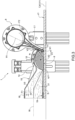
- 1 generally denotes a separation plant 1 according to the present invention.
- the separation plant 1 is configured to separate the particulate matter S along a conveyor system T of products P, i.e. articles, on an advancing plane XY defined by two axes X and Y perpendicular to each other.
- the conveyor system T extends along a longitudinal axis Y1 and the advancing direction V1 of the products P is parallel to the longitudinal axis Y1.
- the products P are flat bodies, namely thin slabs having a length yl, that is, the extension along the longitudinal axis Y, and a width xb, that is, the extension along the axis X, much greater than the thickness zh, that is, the extension along an axis Z perpendicular to the advancing plane XY.
- the products P have an upper surface c1 substantially parallel to the advancing plane XY. Without losing generality, the products P may have different shapes and sizes and may not be flat.
- the advancing plane XY is used as a reference for expressions such as horizontal (parallel to the advancing plane XY), vertical (perpendicular to the advancing plane XY) or the like.
- the products P are slabs (such as tiles).
- the products P may be made, for example, of ceramic material, composite material, wood, veneered material or the like.
- the separation plant 1 according to the present invention may be installed at any position along the conveyor system T.
- the separation plant 1 may be installed along the conveyor system T either at a workstation or at any other position downstream or upstream of a workstation.
- the separation plant 1 sucks in and separates the particulate matter S from the environment of the conveyor system T.
- the separation plant 1 is configured to sanitize the air of the environment of the conveyor system T so as to prevent the propagation of viruses or bacteria into the environment, as will be better shown below.
- the separation plant 1 comprises a collection system 2, which is configured to suck in the particulate matter S from the environment using a carrier gas flow F1 ( Figure 3 ), and a separation system 3 which is configured to separate the particulate matter S from the carrier gas flow F1.
- the separation plant 1 further comprises a compressor 4, in particular a fan, connected to the collection system 2.
- the compressor 4 generates a depression so as to extract through the collection system 2 some gas, which constitutes the carrier gas flow F1, from the environment of the conveyor system T.
- the separation system 3 is interposed between the collection system 2 and the compressor 4.
- the separation plant 1 comprises: a suction conduit 5, fluidically connecting the collection system 2 with the separation system 3, and an outlet conduit 6 fluidically connecting the separation system 3 with the compressor 4.
- the separation system 3 is a cyclone separator. Without losing generality and according to non-shown variants the separation system 3 may be of a different type.
- the collection system 2 has a suction mouth 9 which lies on a plane xy1 substantially parallel to the advancing plane xy of the product P.
- the distance z1 between the plane xy1 and the upper surface c1 of the product P is extremely limited.
- the distance z is less than or equal to 2.5 cm.
- the separation plant 1 further comprises a filtering device 7 arranged along the outlet conduit 6 and interposed between the separation system 3 and the compressor 4.
- the filtering device 7 is also capable of filtering out viruses or bacteria carried by the particulate matter S.
- the filtering device 7 comprises a HEPA filter (High Efficiency Particulate Air filter) according to Standard EN 1822-2009 (EU), typically used for controlled atmospheres in clean rooms.
- HEPA filter High Efficiency Particulate Air filter
- the separation plant 1 comprises a diffuser 8 installed downstream of the compressor 4 and getting a pushing flow F2 from the compressor 4 itself.
- the diffuser 8 is installed downstream of the collection system 2 and is configured to generate an air blade L1 going in a direction V2, which is against the advancing direction V1 of the product P ( Figure 3 ).
- the diffuser 8 is configured to blow an air blade L1 ( Figure 3 ) substantially parallel to a plane n1.
- the plane n1, i.e., the air blade L1 is inclined in respect to the plane xy1 of the suction mouth 9 by an angle of inclination ⁇ .
- the plane n1, i.e., the air blade L1 is incident with the longitudinal axis Y1.
- the plane n1 intersects with the plane xy1 along a straight line X1 parallel to the axis X.
- the air blade L1 impacts, in use, on the product P so as to cause the detachment of any dust particles S that have not separated from the product P under the action of the extraction of the carrier gas flow F1.
- the angle of inclination ⁇ is such that, once detached, the particulate matter S is directed towards the suction mouth 9.
- the angle of inclination ⁇ is greater than 90°.
- the angle of inclination ⁇ is ranging between 90° and 180°.
- the carrier gas flow F1 has a component of horizontal motion V3 with direction opposite to the advancing direction V1 of the product P. In other words, the carrier gas flow F1 is against the advancing direction V1 of the product P.
- This allows to add, advantageously, the separation action of the air blade L1 in combination with the extraction of the carrier gas flow F1 obtaining a complete separation of the dust particles S from the product P. In this way, the separation plant 1 has an extremely high suction efficiency of the particulate matter S with values that can exceed 90-95%.
- the collection system 2 and the diffuser 8 are side by side so as to demarcate with the upper surface c1 of the product P a substantially closed suction chamber 10.
- the only communication passage between the suction chamber 10 and the outside is given by the distance z1 between the plane xy1 of the suction mouth 9 and the upper surface c1 of the product P.
- the distance z1 tends to be zero, i.e. to be as small as possible.
- a minimum distance z1 is due to prevent the collection system 2 from rubbing against the upper surface c1 of the product P and, thus, to avoid potential damage to the upper surface c1 by rubbing.
- the suction chamber 10 is substantially a closed volume.
- the air chamber 10 allows to confine in a closed volume either the pushing action of the air blade L1 or the extraction action of the carrier gas flow F1.
- the efficiency of the separation plant 1 is optimized either in terms of the power required for operation (extremely limited) or in terms of the percentage of particulate matter S sucked in.
- the collection system 2 comprises a sheath 11 which, in use, is arranged abutting against a respective wall (or seat) of the diffuser 8.
- the gasket 8 hermetically closes the air chamber 10 along the connection area between the collection system 2 and the diffuser 8.
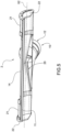
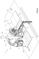
- the collection system 2 comprises a hood 12 configured to be connected to the suction conduit 5.
- the hood 12 is a hollow body.
- the hood 12 comprises a wall 14 which delimits a suction area A (shown in Figures 6I and 6II ), which constitutes, at least in part, the suction chamber 10 and is exposed in use to the particulate matter S to be sucked.
- the extension of the suction area A is as small as possible so as to locally concentrate the action of the carrier gas flow F1.
- the wall 14 is bent.
- the wall 14 has a longitudinal axis X2 which is transversal, in particular perpendicular, to the advancing direction V1.
- the longitudinal axis X2 is an axis of symmetry of the wall 14.
- the hood 12 also comprises a connection 15 configured to connect the wall 14 to the suction conduit 5.
- connection 15 is internally hollow and has a suction cavity 19 that is configured to put the suction area A in communication with the suction conduit 5.
- the connection 15 is divided in a shaped profile portion 16 and in a coupling portion 18.
- the connection 15 is fluidly connected with the suction area A through an opening 20.
- the shaped profile portion 16 is interposed between the wall 14 and the coupling portion 18.
- the shaped profile portion 16 is such as to generate a Venturi effect in the suction cavity 19 and by the opening 20.
- the suction cavity 19 has a variable cross-sectional passage area.
- the passage area of the suction cavity 19 increases from the opening 20 towards the coupling portion 18.
- the profile of the passage area of the suction cavity 19 is also variable along the shaped profile portion 16.
- the passage area of the suction cavity 19 is substantially triangular in correspondence of the opening 20 (i.e., the opening 20 is substantially triangular in shape).
- the passage area of the suction cavity 19 is substantially circular at the coupling portion 18.
- the coupling portion 18 is substantially a tubular body having a longitudinal axis W.
- the Venturi effect generated by the shape of the shaped profile portion 16 allows to amplify the depression of the carrier gas flow F1 and, consequently, the suction capacity of the hood 12.
- the suction area A is delimited by the wall 14 which is a bent wall of reduced height, the overall dimensions of the hood 12 are limited.
- the hood 12 allows the extraction force of the hood 12 to be concentrated and localized in an area.
- the hood 12 is substantially flat. This increases the flexibility and ease of installation with a significant reduction in overall dimensions.
- the suction area A is delimited by a single wall 14 which satisfies predefined technical specifications.
- This allows the hood 12 to be used as a central module of a more complex structure of the collection system 2 as will be better shown below.
- the fact that the hood 12 has a fixed geometry and dimensions allows technologies such as injection moulding of polymeric materials to be used for the realization thereof, which despite the high costs for the equipment allows a high productivity.
- the hood 12 is made of polymeric material, this allows reducing the weight of the hood 12 by facilitating its transportation and installation.
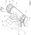
- the collection system 2 also comprises lateral wings 21 to adapt the width, i.e. the extension along the axis X, of the collection system 2 itself to the effective width of the conveyor system T.
- the lateral wings 21 are not made in one piece with the wall 14, in other words they are distinct bodies each of which is connected to a respective longitudinal end of the wall 14.
- Each lateral wing 21 is a laminar body having a shape substantially similar to that of the wall 14. In other words, each lateral wing 21 constitutes an extension of the wall 14 along the longitudinal axis X2.
- each lateral wing 21 is made by extrusion.
- a piece of extrusion can be cut at will to obtain a lateral wing 21 of any length.
- each collection system 2 This allows the width of each collection system 2 to be adapted to the width of the conveyor system T according to the longitudinal extension of each lateral wing 21.
- the extension along the longitudinal axis X2 of the collection system 2 is substantially equal to the width of the conveyor system T. In this way, it is ensured that the suction chamber 10 is closed, in use, inferiorly by the product P so as to reduce any air leakage.
- each lateral wing 21 may be releasably connected to the wall 14. In this way it is possible to change the width even of a collection system 2.
- the collection 2 comprises two caps 22 ( Figure 4 ), each of which laterally closes a free end of a respective lateral wing 21.
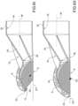
- connection 15 is mounted rotatable in respect to the wall 14.
- the longitudinal axis W of the coupling portion 18 may be rotated about the longitudinal axis X2 of the hood 12.
- the connection 15 may assume any position between a flattened position PI, in which the longitudinal axis W is substantially parallel to the plane xy1 to a raised position PII in which the longitudinal axis W is inclined at an angle ⁇ in respect to the flattened position PI.
- the acute angle is ranging between 0° and 60°.
- the connection 15 can be rotated about the longitudinal axis X2 allows for a greater flexibility in installation and adaptability of the collection system 2 even to existing conveyor systems T or with reduced installation space.
- the collection system 2 has a leading edge 23 and longitudinally delimits the collection system 2 itself.
- the leading edge 23 is substantially parallel to the longitudinal axis X2.
- the leading edge 23 is spaced apart from the plane xy1 of the suction mouth 9.
- the sheath 11 is applied to the leading edge 23, which is configured to come into contact in use, against the distributor 8 so as to close the suction chamber 10 at the top.
- the collection system 2 has the shape of a semi-cylinder, the leading edge 23 lies on the plane xy1 of the suction mouth 9.
- the suction area A corresponds to the suction chamber 10.
- This second configuration shown in Figure 6II is suitable for the embodiment of the variant of the separation plant 1 shown in Figure 8 .
- Figure 8 shows a variant of the separation plant 1 according to the present invention.
- the components in common with the solution described above are considered contained herein and maintain the same numbering and are not repeated for brevity's sake.
- the separation plant 1 is without the diffuser and the compressor 4 is connected to a discharge conduit 24 and conveys the pushing fluid F2 inside the discharge conduit 24.
- the discharge conduit 24 may be connected, for example, to a central air collection pipe (not shown).
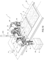
- Figure 9 shows a variant of the separation plant 1 of Figure 1 , the components being substantially doubled and installed on opposite sides of the conveyor system T.
- the components of the plant 1 maintain the same numbering and bear the endings I and II for the components to the left and, respectively, to the right of the conveyor system.
- the plant 1 comprises two collection systems 12I and 12II side by side and communicating so as to form a single suction chamber 10.
- Each collection system 12I and 12II is connected to a respective separation system 3I and 3II and a ventilation machine 4I and 4II.
- a respective filtering device 7I and 7II is arranged between each separation system 3I and 3II and the respective ventilation machine 4I and 4II.
- the separation plant 1 of the type described above can be adapted to conveyor lines T of any width.
- the separation plant 1 comprises a single diffuser 8 of substantially doubled length and fed by both compressors 4I and 4II.
- the separation plant 1 may comprise doubled components placed side by side but not communicating with each other, i.e. the hoods 12 may be placed side by side but not communicating with each other and the diffuser 8 instead of being of doubled length may be divided into two distinct bodies.
- Figure 10 shows a variant of the separation plant 1 shown in Figure 8 in which the components are substantially doubled like in the example shown in Figure 9 .
- the compressor 4 is activated so as to generate a depression such as to cause the air from the external environment to be sucked in through the collection system 2 generating a carrier gas flow F1.
- the carrier gas flow F1 entrains the particulate matter S within the collection hood 2 and into the suction conduit 5.
- a dirty product P i.e. on which material (dust, chips or the like) is deposited, which must be separated from the product P and constitutes at least part of the particulate matter S, advances in the advancing direction V1 and is made to slide below the separation hood 2.
- the product P By advancing below the separation hood 2, the product P inferiorly closes the suction area A of the separation hood 2 so as to inferiorly demarcate the suction chamber 10 ( Figure 3 ).
- the carrier gas flow F1 entrains the particles as particulate matter S sucking it into the suction conduit 5.
- the suction chamber is demarcated on at least one side by an air blade L1 blown from the diffuser 8 itself.
- the air blade L1 helps to separate material adhering to the product P and making it dirty.
- the air blade L1 is substantially perpendicular to the advancing direction V1 and is inclined in respect to the plane xy1 of the suction mouth 9 by an angle ⁇ greater than 90°, in this way the air blade L1 in addition to separating the material deposited on the product P allows to direct the particulate matter S towards the suction mouth 9 increasing the efficiency of the separation plant 1.
- the diffuser 8 is fed by a pushing flow F2 generated by the same compressor 4 that generates the carrier gas flow F1.
- a closed air cycle of reduced dimensions and extremely efficient is generated, which requires modest powers for its operation.
- the particulate matter S is sucked along the suction conduit 5 and within the separation system 3.
- the separation system 3 the particulate matter S is divided by the fluid (air) that constitutes the carrier gas flow F1.
- the separation system 3 is a cyclone separator and the particulate matter S is made to accumulate within a special container 25 integrated into the separation system, or within a disposal bag or a pipe leading to a centralised tank 26 (the latter hypothesis is schematized by way of example in table 10).
- the carrier gas flow F1 passes through the filtering device 7.
- the filtering device 7 comprises a HEPA-type filter, in this way it is possible to sanitize the carrier gas flow F1 by eliminating any viruses or bacteria and contributing to the sanitization of the environments.
- the filtering device 7 may comprise multiple degrees of filtration so as to allow the complete removal of particulate matter S from the carrier gas flow F1.
- the compressor 2 is connected at the outlet to a discharge conduit 24.
- the pushing flow F2 is conveyed to a discharge, as it could be a centralised air discharge plant. This ensures that air that is not sucked into the work environment is not recirculated locally.
- the separation plant 1 is modular, so that components can be duplicated in case of particularly large conveyor systems T.
- the separation plant 1 of the type described above can be easily adapted to any type of conveyor system.
- the separation plant 1 of the type described above is easy to install and takes up little space.
- the separation plant 1 of the type described above requires reduced power compared to conventional separation plants.
- the hood 12 of the collection system 2 can be made with standard components produced with large-scale production processes, for example moulding or extrusion. This allows economies of scale to be applied and reduces the cost of the separation plant 1.
- the separation plant 1 of the type described above is independent and does not need to be connected to expensive centralised plants.
- the collection system 2 has extremely reduced dimensions and is substantially flattened on the conveyor system T. This allows the collection system 2 to be installed in substantially any position.
- the coupling portion 18 that is tubular and inclined in respect to the hood 12 allows a connection to be made with the suction conduit 5 that is inclined in respect to the advancing plane XY. This makes it possible to reduce the vertical dimensions of the separation plant 1 and to be able to adapt the collection system 2 also to already existing conveyor systems T with structural constraints.
Landscapes
- Chemical & Material Sciences (AREA)
- Chemical Kinetics & Catalysis (AREA)
- Engineering & Computer Science (AREA)
- Mechanical Engineering (AREA)
- Filtering Of Dispersed Particles In Gases (AREA)
- Preparation Of Compounds By Using Micro-Organisms (AREA)
- Electrical Discharge Machining, Electrochemical Machining, And Combined Machining (AREA)
Claims (8)
- Sammelsystem für partikelförmige Stoffe (S) entlang eines Fördersystems (T) von Produkten (P), die sich in einer Vorschubrichtung (V1) vorwärts bewegen, mittels eines Trägergasstroms (F1); wobei das Sammelsystem (2) eine Haube (12) umfasst, die ihrerseits eine gebogene Wand (14), die gekrümmt ist und einen Saugbereich (A) begrenzt, und eine Verbindung (15) umfasst, die den Saugbereich (A) durch eine Öffnung (20) der gebogenen Wand (14) mit einer Saugleitung (5) fluidmäßig verbindet; wobei die gebogene Wand (14) eine Längsachse (X2) aufweist, die im Gebrauch quer, insbesondere senkrecht, zu der Vorschubrichtung (V1) der Produkte (P) verläuft; dadurch gekennzeichnet, dass das Sammelsystem einen oder zwei seitliche Flügel (21) umfasst, wobei jeder seitliche Flügel (21) lösbar mit einem jeweiligen Ende der gebogenen Wand (14) der Haube (12) verbunden ist; wobei jeder seitliche Flügel (21) ein laminarer Körper ist und einen Querschnitt mit einer Form ähnlich der der gebogenen Wand (14) aufweist; wobei jeder seitliche Flügel (21) eine Verlängerung der gebogenen Wand (14) ist.
- Sammelsystem nach Anspruch 1, wobei die gebogene Wand (14) aus einem einzigen Körper hergestellt ist.
- Sammelsystem nach einem der vorhergehenden Ansprüche, wobei die Verbindung (15) innen hohl ist und einen Ansaughohlraum (19) aufweist, der im Gebrauch den Saugbereich (A) mit der Saugleitung (5) verbindet; wobei die Verbindung (15) in einen geformten Profilabschnitt (16) und in einen Kupplungsabschnitt (18) unterteilt ist; der geformte Profilabschnitt (16) zwischen der gebogenen Wand (14) und dem Kupplungsabschnitt (18) angeordnet ist; wobei der geformte Profilabschnitt (16) so gestaltet ist, dass er an der Öffnung (20) eine Vertiefung erzeugt.
- Sammelsystem nach einem der vorhergehenden Ansprüche, wobei die Haube (12) aus einem polymeren Material hergestellt und durch Gießen geformt ist.
- Sammelsystem nach einem der vorhergehenden Ansprüche, wobei jeder Seitenflügel (21) durch Extrusion hergestellt ist.
- Verfahren zur Herstellung eines Sammelsystems (2) nach einem der vorhergehenden Ansprüche, bei dem eine Haube (2) durch Formen von polymerem Material hergestellt wird, wobei die Haube (2) eine gebogene Wand (14), die gekrümmt ist und einen Saugbereich (A) begrenzt, und eine Verbindung (15) aufweist, die den Saugbereich (A) durch eine Öffnung (20) der gebogenen Wand (14) mit der Außenseite fluidisch verbindet; wobei die gebogene Wand (14) eine Längsachse (X2) aufweist, die im Gebrauch quer, insbesondere senkrecht, zur Vorschubrichtung (V1) der Produkte (P) verläuft; wobei das Verfahren die folgenden weiteren Schritte umfasst: Bereitstellen von einem oder zwei Seitenflügeln (21), von denen jeder ein laminarer Körper ist, der sich entlang einer Längsachse erstreckt, die im Gebrauch koaxial zu der Längsachse (X2) ist; Verbinden jedes Seitenflügels (21) mit einem jeweiligen Ende der gebogenen Wand (14).
- Herstellungsverfahren nach Anspruch 6, wobei der Schritt des Bereitstellens den Teilschritt des Auswählens jedes Seitenflügels (21) in Abhängigkeit von der Breite des Fördersystems (T), auf dem das Sammelsystem (2) im Gebrauch angeordnet ist, umfasst.
- Herstellungsverfahren nach Anspruch 6 oder 7, wobei das Sammelsystem (2) eine Verbindung (15) zum Verbinden der gebogenen Wand (14) mit einer Saugleitung (5) umfasst; wobei die Verbindung (15) ein Hohlkörper mit einer Achse (W) ist; wobei das Verfahren den Schritt des Einstellens der Neigung der Verbindung (15) in Bezug auf die gebogene Wand (14) um einen Winkel (β) im Bereich zwischen 0° und 60° in Bezug auf eine Vorschubebene (XY) der Produkte (P) umfasst.
Applications Claiming Priority (1)
| Application Number | Priority Date | Filing Date | Title |
|---|---|---|---|
| IT102020000012211A IT202000012211A1 (it) | 2020-05-25 | 2020-05-25 | Sistema di captazione e processo di produzione di tale sistema di captazione |
Publications (3)
| Publication Number | Publication Date |
|---|---|
| EP3915693A1 EP3915693A1 (de) | 2021-12-01 |
| EP3915693C0 EP3915693C0 (de) | 2023-12-06 |
| EP3915693B1 true EP3915693B1 (de) | 2023-12-06 |
Family
ID=72086988
Family Applications (1)
| Application Number | Title | Priority Date | Filing Date |
|---|---|---|---|
| EP21175815.6A Active EP3915693B1 (de) | 2020-05-25 | 2021-05-25 | Sammelsystem und verfahren zur herstellung des sammelsystems |
Country Status (6)
| Country | Link |
|---|---|
| US (1) | US12049370B2 (de) |
| EP (1) | EP3915693B1 (de) |
| CN (1) | CN113714240A (de) |
| BR (1) | BR102021010017A2 (de) |
| ES (1) | ES2967241T3 (de) |
| IT (1) | IT202000012211A1 (de) |
Families Citing this family (2)
| Publication number | Priority date | Publication date | Assignee | Title |
|---|---|---|---|---|
| US11318509B2 (en) * | 2017-11-06 | 2022-05-03 | Air Systems Design, Inc. | Dust hood |
| CN116214622B (zh) * | 2023-05-09 | 2023-08-04 | 山东三岭汽车内饰有限公司 | 一种重卡内饰生产过程中玻璃纤维增强塑料的回收装置 |
Family Cites Families (18)
| Publication number | Priority date | Publication date | Assignee | Title |
|---|---|---|---|---|
| JP2820599B2 (ja) * | 1993-08-31 | 1998-11-05 | 株式会社伸興 | 除塵装置 |
| JP2002112930A (ja) * | 2000-10-12 | 2002-04-16 | Misako Sato | 電気掃除機における吸込区分化清掃の方法と装置 |
| JP2003334499A (ja) * | 2002-05-21 | 2003-11-25 | Hojitsu Seiko Kk | ダスト除去装置及びダスト除去方法 |
| US7931755B2 (en) * | 2003-12-19 | 2011-04-26 | Mitsuboshi Diamond Industrial Co., Ltd | Method for removing deposit from substrate and method for drying substrate, as well as apparatus for removing deposit from substrate and apparatus for drying substrate using these methods |
| WO2008108168A1 (ja) * | 2007-03-08 | 2008-09-12 | Nisshin Engineering Inc. | ノズル、ドライクリーナ及びドライクリーナシステム |
| JP2009148699A (ja) * | 2007-12-20 | 2009-07-09 | Toppan Printing Co Ltd | 基板処理装置 |
| JP2009160536A (ja) * | 2008-01-09 | 2009-07-23 | Kaneka Corp | 付着異物除去装置、付着異物除去方法及びシート状物 |
| ITMI20081162A1 (it) * | 2008-06-26 | 2009-12-27 | Danieli Off Mecc | Dispositivo per la rimozione di liquido o particelle solide da una superficie piana di un prodotto metallico |
| US9931678B2 (en) * | 2013-11-12 | 2018-04-03 | Inter-Source Recovery Systems | Pneumatic chip collector |
| KR102272661B1 (ko) * | 2014-10-02 | 2021-07-06 | 삼성디스플레이 주식회사 | 기판 세정 장치 |
| KR101649418B1 (ko) * | 2014-12-01 | 2016-08-18 | 엘지전자 주식회사 | 청소기의 노즐 및 진공 청소기 |
| JP6781944B2 (ja) * | 2016-03-15 | 2020-11-11 | 大日本印刷株式会社 | 異物除去装置 |
| IT201600130256A1 (it) * | 2016-12-22 | 2018-06-22 | Wamgroup Spa | Depolveratore per fluidi gassosi e metodo per realizzarlo |
| CN206567291U (zh) * | 2017-01-26 | 2017-10-20 | 东莞市求是测试设备有限公司 | 一种pcb板表面清理装置 |
| KR101894037B1 (ko) * | 2018-03-16 | 2018-09-04 | 에스제이이 주식회사 | 컨베이어 벨트 크리닝 장치 |
| CN109530296B (zh) * | 2018-09-10 | 2022-03-22 | 惠科股份有限公司 | 一种清洗方法和清洗装置 |
| IT202000012205A1 (it) * | 2020-05-25 | 2021-11-25 | F M Srl | Processo e impianto di separazione di materiale sospeso |
| US11242210B1 (en) * | 2021-08-23 | 2022-02-08 | Steven Bitondo | Portable brushless conveyor belt cleaner system |
-
2020
- 2020-05-25 IT IT102020000012211A patent/IT202000012211A1/it unknown
-
2021
- 2021-05-24 BR BR102021010017-6A patent/BR102021010017A2/pt unknown
- 2021-05-24 US US17/328,097 patent/US12049370B2/en active Active
- 2021-05-25 ES ES21175815T patent/ES2967241T3/es active Active
- 2021-05-25 CN CN202110574760.3A patent/CN113714240A/zh active Pending
- 2021-05-25 EP EP21175815.6A patent/EP3915693B1/de active Active
Also Published As
| Publication number | Publication date |
|---|---|
| EP3915693C0 (de) | 2023-12-06 |
| ES2967241T3 (es) | 2024-04-29 |
| CN113714240A (zh) | 2021-11-30 |
| US12049370B2 (en) | 2024-07-30 |
| BR102021010017A2 (pt) | 2021-11-30 |
| US20210362964A1 (en) | 2021-11-25 |
| IT202000012211A1 (it) | 2021-11-25 |
| EP3915693A1 (de) | 2021-12-01 |
Similar Documents
| Publication | Publication Date | Title |
|---|---|---|
| US11780687B2 (en) | Separation process and plant for particulate matter | |
| EP3915693B1 (de) | Sammelsystem und verfahren zur herstellung des sammelsystems | |
| KR101776575B1 (ko) | 연마재 회수 시스템을 갖는 블라스트 가공 방법 및 장치, 박막 태양전지 패널의 가공 방법 및 이에 의해 가공된 박막 태양전지 패널 | |
| KR101653222B1 (ko) | 연마재 회수 시스템을 갖는 블라스트 가공 방법 및 장치, 박막 태양전지 패널의 가공 방법 및 이에 의해 가공된 박막 태양전지 패널 | |
| US9358668B2 (en) | Fluid jet receiving receptacles and related fluid jet cutting systems | |
| KR20080080617A (ko) | 재료반송 및 배출기 장치용 방법 및 장치 | |
| KR101604923B1 (ko) | 공기노즐을 이용한 동시 흡배기 방식의 절삭유 흡입청소기와 공작기계의 연결기구 | |
| CN107530664A (zh) | 连续式粒子制造装置 | |
| EP3197605B1 (de) | Staub- und gasausstossventil | |
| KR100597683B1 (ko) | 대형 공작기계용 가공칩 처리 시스템 | |
| CN111185667B (zh) | 一种抽排装置及激光切割装置 | |
| EP0189104B1 (de) | Stofflöser | |
| KR20170025724A (ko) | 비산먼지 제거용 벌크호퍼 | |
| CN219724954U (zh) | 轻质物料回收分离系统 | |
| CN209956962U (zh) | 一种真空输送机 | |
| CN214861937U (zh) | 一种不易沉降轻质粉料用离线喷吹除尘器 | |
| CN112024054B (zh) | 一种磨粉系统 | |
| CN213226699U (zh) | 一种竹板加工用碎屑收集装置 | |
| CN116275568B (zh) | 轻质物料回收分离系统 | |
| CN222790122U (zh) | 一种激光焊接自动化除尘线 | |
| CN112936895A (zh) | 自清洁口罩生产机 | |
| CN223439465U (zh) | 一种粉尘回收装置 | |
| CN219990213U (zh) | 一种产品输送机 | |
| CN222710373U (zh) | 一种便携式碎屑清洁工具 | |
| CN212071639U (zh) | 建筑装饰装修用喷砂机 |
Legal Events
| Date | Code | Title | Description |
|---|---|---|---|
| PUAI | Public reference made under article 153(3) epc to a published international application that has entered the european phase |
Free format text: ORIGINAL CODE: 0009012 |
|
| STAA | Information on the status of an ep patent application or granted ep patent |
Free format text: STATUS: THE APPLICATION HAS BEEN PUBLISHED |
|
| AK | Designated contracting states |
Kind code of ref document: A1 Designated state(s): AL AT BE BG CH CY CZ DE DK EE ES FI FR GB GR HR HU IE IS IT LI LT LU LV MC MK MT NL NO PL PT RO RS SE SI SK SM TR |
|
| B565 | Issuance of search results under rule 164(2) epc |
Effective date: 20211012 |
|
| STAA | Information on the status of an ep patent application or granted ep patent |
Free format text: STATUS: REQUEST FOR EXAMINATION WAS MADE |
|
| 17P | Request for examination filed |
Effective date: 20220311 |
|
| RBV | Designated contracting states (corrected) |
Designated state(s): AL AT BE BG CH CY CZ DE DK EE ES FI FR GB GR HR HU IE IS IT LI LT LU LV MC MK MT NL NO PL PT RO RS SE SI SK SM TR |
|
| GRAP | Despatch of communication of intention to grant a patent |
Free format text: ORIGINAL CODE: EPIDOSNIGR1 |
|
| STAA | Information on the status of an ep patent application or granted ep patent |
Free format text: STATUS: GRANT OF PATENT IS INTENDED |
|
| RIC1 | Information provided on ipc code assigned before grant |
Ipc: B08B 5/04 20060101AFI20230608BHEP |
|
| INTG | Intention to grant announced |
Effective date: 20230626 |
|
| GRAS | Grant fee paid |
Free format text: ORIGINAL CODE: EPIDOSNIGR3 |
|
| GRAA | (expected) grant |
Free format text: ORIGINAL CODE: 0009210 |
|
| STAA | Information on the status of an ep patent application or granted ep patent |
Free format text: STATUS: THE PATENT HAS BEEN GRANTED |
|
| AK | Designated contracting states |
Kind code of ref document: B1 Designated state(s): AL AT BE BG CH CY CZ DE DK EE ES FI FR GB GR HR HU IE IS IT LI LT LU LV MC MK MT NL NO PL PT RO RS SE SI SK SM TR |
|
| REG | Reference to a national code |
Ref country code: GB Ref legal event code: FG4D |
|
| REG | Reference to a national code |
Ref country code: DE Ref legal event code: R096 Ref document number: 602021007408 Country of ref document: DE |
|
| REG | Reference to a national code |
Ref country code: CH Ref legal event code: EP |
|
| REG | Reference to a national code |
Ref country code: IE Ref legal event code: FG4D |
|
| U01 | Request for unitary effect filed |
Effective date: 20231222 |
|
| U07 | Unitary effect registered |
Designated state(s): AT BE BG DE DK EE FI FR IT LT LU LV MT NL PT SE SI Effective date: 20240110 |
|
| PG25 | Lapsed in a contracting state [announced via postgrant information from national office to epo] |
Ref country code: GR Free format text: LAPSE BECAUSE OF FAILURE TO SUBMIT A TRANSLATION OF THE DESCRIPTION OR TO PAY THE FEE WITHIN THE PRESCRIBED TIME-LIMIT Effective date: 20240307 |
|
| REG | Reference to a national code |
Ref country code: ES Ref legal event code: FG2A Ref document number: 2967241 Country of ref document: ES Kind code of ref document: T3 Effective date: 20240429 |
|
| PG25 | Lapsed in a contracting state [announced via postgrant information from national office to epo] |
Ref country code: GR Free format text: LAPSE BECAUSE OF FAILURE TO SUBMIT A TRANSLATION OF THE DESCRIPTION OR TO PAY THE FEE WITHIN THE PRESCRIBED TIME-LIMIT Effective date: 20240307 |
|
| PG25 | Lapsed in a contracting state [announced via postgrant information from national office to epo] |
Ref country code: RS Free format text: LAPSE BECAUSE OF FAILURE TO SUBMIT A TRANSLATION OF THE DESCRIPTION OR TO PAY THE FEE WITHIN THE PRESCRIBED TIME-LIMIT Effective date: 20231206 Ref country code: NO Free format text: LAPSE BECAUSE OF FAILURE TO SUBMIT A TRANSLATION OF THE DESCRIPTION OR TO PAY THE FEE WITHIN THE PRESCRIBED TIME-LIMIT Effective date: 20240306 Ref country code: HR Free format text: LAPSE BECAUSE OF FAILURE TO SUBMIT A TRANSLATION OF THE DESCRIPTION OR TO PAY THE FEE WITHIN THE PRESCRIBED TIME-LIMIT Effective date: 20231206 |
|
| U20 | Renewal fee for the european patent with unitary effect paid |
Year of fee payment: 4 Effective date: 20240514 |
|
| PG25 | Lapsed in a contracting state [announced via postgrant information from national office to epo] |
Ref country code: IS Free format text: LAPSE BECAUSE OF FAILURE TO SUBMIT A TRANSLATION OF THE DESCRIPTION OR TO PAY THE FEE WITHIN THE PRESCRIBED TIME-LIMIT Effective date: 20240406 |
|
| PG25 | Lapsed in a contracting state [announced via postgrant information from national office to epo] |
Ref country code: CZ Free format text: LAPSE BECAUSE OF FAILURE TO SUBMIT A TRANSLATION OF THE DESCRIPTION OR TO PAY THE FEE WITHIN THE PRESCRIBED TIME-LIMIT Effective date: 20231206 |
|
| PG25 | Lapsed in a contracting state [announced via postgrant information from national office to epo] |
Ref country code: SK Free format text: LAPSE BECAUSE OF FAILURE TO SUBMIT A TRANSLATION OF THE DESCRIPTION OR TO PAY THE FEE WITHIN THE PRESCRIBED TIME-LIMIT Effective date: 20231206 |
|
| PG25 | Lapsed in a contracting state [announced via postgrant information from national office to epo] |
Ref country code: SM Free format text: LAPSE BECAUSE OF FAILURE TO SUBMIT A TRANSLATION OF THE DESCRIPTION OR TO PAY THE FEE WITHIN THE PRESCRIBED TIME-LIMIT Effective date: 20231206 Ref country code: SK Free format text: LAPSE BECAUSE OF FAILURE TO SUBMIT A TRANSLATION OF THE DESCRIPTION OR TO PAY THE FEE WITHIN THE PRESCRIBED TIME-LIMIT Effective date: 20231206 Ref country code: RO Free format text: LAPSE BECAUSE OF FAILURE TO SUBMIT A TRANSLATION OF THE DESCRIPTION OR TO PAY THE FEE WITHIN THE PRESCRIBED TIME-LIMIT Effective date: 20231206 Ref country code: IS Free format text: LAPSE BECAUSE OF FAILURE TO SUBMIT A TRANSLATION OF THE DESCRIPTION OR TO PAY THE FEE WITHIN THE PRESCRIBED TIME-LIMIT Effective date: 20240406 Ref country code: CZ Free format text: LAPSE BECAUSE OF FAILURE TO SUBMIT A TRANSLATION OF THE DESCRIPTION OR TO PAY THE FEE WITHIN THE PRESCRIBED TIME-LIMIT Effective date: 20231206 |
|
| PG25 | Lapsed in a contracting state [announced via postgrant information from national office to epo] |
Ref country code: PL Free format text: LAPSE BECAUSE OF FAILURE TO SUBMIT A TRANSLATION OF THE DESCRIPTION OR TO PAY THE FEE WITHIN THE PRESCRIBED TIME-LIMIT Effective date: 20231206 |
|
| PG25 | Lapsed in a contracting state [announced via postgrant information from national office to epo] |
Ref country code: PL Free format text: LAPSE BECAUSE OF FAILURE TO SUBMIT A TRANSLATION OF THE DESCRIPTION OR TO PAY THE FEE WITHIN THE PRESCRIBED TIME-LIMIT Effective date: 20231206 |
|
| REG | Reference to a national code |
Ref country code: DE Ref legal event code: R097 Ref document number: 602021007408 Country of ref document: DE |
|
| PLBE | No opposition filed within time limit |
Free format text: ORIGINAL CODE: 0009261 |
|
| STAA | Information on the status of an ep patent application or granted ep patent |
Free format text: STATUS: NO OPPOSITION FILED WITHIN TIME LIMIT |
|
| 26N | No opposition filed |
Effective date: 20240909 |
|
| REG | Reference to a national code |
Ref country code: CH Ref legal event code: PL |
|
| U1K | Transfer of rights of the unitary patent after the registration of the unitary effect |
Owner name: FM PARTEC S.P.A.; IT |
|
| PG25 | Lapsed in a contracting state [announced via postgrant information from national office to epo] |
Ref country code: MC Free format text: LAPSE BECAUSE OF FAILURE TO SUBMIT A TRANSLATION OF THE DESCRIPTION OR TO PAY THE FEE WITHIN THE PRESCRIBED TIME-LIMIT Effective date: 20231206 |
|
| PG25 | Lapsed in a contracting state [announced via postgrant information from national office to epo] |
Ref country code: MC Free format text: LAPSE BECAUSE OF FAILURE TO SUBMIT A TRANSLATION OF THE DESCRIPTION OR TO PAY THE FEE WITHIN THE PRESCRIBED TIME-LIMIT Effective date: 20231206 Ref country code: CH Free format text: LAPSE BECAUSE OF NON-PAYMENT OF DUE FEES Effective date: 20240531 |
|
| REG | Reference to a national code |
Ref country code: ES Ref legal event code: PC2A Owner name: FM PARTEC S.P.A. Effective date: 20250219 |
|
| PG25 | Lapsed in a contracting state [announced via postgrant information from national office to epo] |
Ref country code: IE Free format text: LAPSE BECAUSE OF NON-PAYMENT OF DUE FEES Effective date: 20240525 |
|
| U20 | Renewal fee for the european patent with unitary effect paid |
Year of fee payment: 5 Effective date: 20250508 |
|
| PGFP | Annual fee paid to national office [announced via postgrant information from national office to epo] |
Ref country code: ES Payment date: 20250611 Year of fee payment: 5 |
|
| PG25 | Lapsed in a contracting state [announced via postgrant information from national office to epo] |
Ref country code: HU Free format text: LAPSE BECAUSE OF FAILURE TO SUBMIT A TRANSLATION OF THE DESCRIPTION OR TO PAY THE FEE WITHIN THE PRESCRIBED TIME-LIMIT; INVALID AB INITIO Effective date: 20210525 |
|
| PG25 | Lapsed in a contracting state [announced via postgrant information from national office to epo] |
Ref country code: CY Free format text: LAPSE BECAUSE OF FAILURE TO SUBMIT A TRANSLATION OF THE DESCRIPTION OR TO PAY THE FEE WITHIN THE PRESCRIBED TIME-LIMIT; INVALID AB INITIO Effective date: 20210525 |