EP3914539B1 - Verfahren und vorrichtung zum zuführen und fördern von material - Google Patents
Verfahren und vorrichtung zum zuführen und fördern von material Download PDFInfo
- Publication number
- EP3914539B1 EP3914539B1 EP20744462.1A EP20744462A EP3914539B1 EP 3914539 B1 EP3914539 B1 EP 3914539B1 EP 20744462 A EP20744462 A EP 20744462A EP 3914539 B1 EP3914539 B1 EP 3914539B1
- Authority
- EP
- European Patent Office
- Prior art keywords
- channel
- feed
- container
- material conveying
- input point
- Prior art date
- Legal status (The legal status is an assumption and is not a legal conclusion. Google has not performed a legal analysis and makes no representation as to the accuracy of the status listed.)
- Active
Links
Images

Classifications
-
- B—PERFORMING OPERATIONS; TRANSPORTING
- B65—CONVEYING; PACKING; STORING; HANDLING THIN OR FILAMENTARY MATERIAL
- B65F—GATHERING OR REMOVAL OF DOMESTIC OR LIKE REFUSE
- B65F5/00—Gathering or removal of refuse otherwise than by receptacles or vehicles
- B65F5/005—Gathering or removal of refuse otherwise than by receptacles or vehicles by pneumatic means, e.g. by suction
-
- B—PERFORMING OPERATIONS; TRANSPORTING
- B65—CONVEYING; PACKING; STORING; HANDLING THIN OR FILAMENTARY MATERIAL
- B65F—GATHERING OR REMOVAL OF DOMESTIC OR LIKE REFUSE
- B65F1/00—Refuse receptacles; Accessories therefor
- B65F1/10—Refuse receptacles; Accessories therefor with refuse filling means, e.g. air-locks
- B65F1/105—Refuse receptacles; Accessories therefor with refuse filling means, e.g. air-locks the filling means being pneumatic, e.g. using suction
-
- B—PERFORMING OPERATIONS; TRANSPORTING
- B65—CONVEYING; PACKING; STORING; HANDLING THIN OR FILAMENTARY MATERIAL
- B65G—TRANSPORT OR STORAGE DEVICES, e.g. CONVEYORS FOR LOADING OR TIPPING, SHOP CONVEYOR SYSTEMS OR PNEUMATIC TUBE CONVEYORS
- B65G43/00—Control devices, e.g. for safety, warning or fault-correcting
- B65G43/08—Control devices operated by article or material being fed, conveyed or discharged
-
- B—PERFORMING OPERATIONS; TRANSPORTING
- B65—CONVEYING; PACKING; STORING; HANDLING THIN OR FILAMENTARY MATERIAL
- B65G—TRANSPORT OR STORAGE DEVICES, e.g. CONVEYORS FOR LOADING OR TIPPING, SHOP CONVEYOR SYSTEMS OR PNEUMATIC TUBE CONVEYORS
- B65G51/00—Conveying articles through pipes or tubes by fluid flow or pressure; Conveying articles over a flat surface, e.g. the base of a trough, by jets located in the surface
- B65G51/04—Conveying the articles in carriers having a cross-section approximating that of the pipe or tube; Tube mail systems
- B65G51/22—Arrangements for stopping the carriers en route in order to control carrier sequence; Blocking or separating devices
-
- B—PERFORMING OPERATIONS; TRANSPORTING
- B65—CONVEYING; PACKING; STORING; HANDLING THIN OR FILAMENTARY MATERIAL
- B65G—TRANSPORT OR STORAGE DEVICES, e.g. CONVEYORS FOR LOADING OR TIPPING, SHOP CONVEYOR SYSTEMS OR PNEUMATIC TUBE CONVEYORS
- B65G53/00—Conveying materials in bulk through troughs, pipes or tubes by floating the materials or by flow of gas, liquid or foam
- B65G53/34—Details
Definitions
- the invention relates to an apparatus according to the preamble of claim 1.
- the invention also relates to a method according to claim 11.
- the invention relates generally to material conveying systems, such as to pneumatic partial-vacuum transporting systems, particularly to the collection and conveying of wastes, such as to the conveying of household wastes.
- material conveying systems such as to pneumatic partial-vacuum transporting systems
- Such systems are presented e.g. in publications WO 2009/080880 , WO 2009/080881 , WO 2009/080882 , WO 2009/080883 , WO 2009/080884 , WO 2009/080885 , WO 2009/080886 , WO 2009/080887 and WO 2009/080888 .
- the invention also relates to waste feeding means, such as to input points or refuse chutes, with which waste is conveyed, typically by gravity, for example in residential buildings from higher feed apertures to a lower collection space or corresponding container.
- Waste input points for example rubbish containers or refuse chutes, are used in the systems at the waste material input end, into which waste input points the material, such as waste material, is fed and from which waste input points the material to be conveyed is conveyed into the conveying pipe by opening a discharge valve means, in which case, by means of the sucking effect achieved by the aid of a partial vacuum acting in the conveying pipe and also by means of the surrounding air pressure acting via the refuse chute, material such as for example waste material packed into bags, is conveyed from the refuse chute into the conveying pipe and onwards to a reception point, where the waste material to be transported is separated from the transporting air and conveyed for further processing or for example into a shipping container.
- a discharge valve means in which case, by means of the sucking effect achieved by the aid of a partial vacuum acting in the conveying pipe and also by means of the surrounding air pressure acting via the refuse chute, material such as for example waste material packed into bags, is conveyed from the refuse chute into the conveying pipe and onwards to a reception
- the pneumatic wastes conveying systems in question can be utilized particularly well in densely populated urban areas. These types of areas have tall buildings, in which the input of wastes into the pneumatic conveying system for wastes is performed via an input point, such as a refuse chute, arranged in the building.
- the object of this invention is to provide a completely novel solution in connection with refuse chutes of a wastes conveying system, by means of which the problems of the prior solutions can be avoided.
- the invention is based on an idea in which a material conveying channel, for example a refuse chute, comprising at least two input points is provided with at least one stopper means between a feed-in container of at least one of the input points and a feed aperture of the material conveying channel, which stopper means has at least two positions, a first position in which the stopper means extends to a passageway leading to the material conveying channel and limits the passage of material from the feed-in container to the material conveying channel, and a second position in which the stopper means does not essentially limit the conveying of material from the feed-in container to the material conveying channel, and that a connection is provided from a second feed-in container to the material conveying channel, to a container space arranged or formed in a lower part thereof.
- Material may be fed simultaneously from different feed apertures of an input point, whereby a first material kind is arranged to be directed to the lower part of the material channel, to a storage space, and a second material fraction to a container space of the second feed-in container of the input point and is stored therein when the stopper means is disposed in the first position.
- the feed-in containers of different input points may be emptied in a controlled manner by acting on the stopper means for example in an order from the bottom to the top in stages or floor by floor, by moving the stopper means from the first position to the second position.
- the apparatus according to the invention is mainly characterized by the features described in claim 1.
- the apparatus according to the invention is additionally characterized by the features described in claims 2 - 10.
- the method according to the invention is mainly characterized by the features described in claim 11.
- the solution according to the invention has many significant advantages.
- simultaneous use of different input points of the material conveying channel is enabled in the material feeding stage.
- the partitioned material space of the input points of the material conveying channel may be utilized in the temporary storage of material more efficiently than before.
- the possibility to feed some of the input points is out of use for only a short time in the material conveying stage.
- efficient emptying of the input points and conveying of the material by means of gravity and suction generated by the partial-vacuum generator of the material conveying system are enabled, and at the same time the feed-in containers of at least part of the input points may be utilized for the storage of material.
- the input point arrangement according to the invention may be arranged so as to take a reasonably small space. Hatches of the input points or hoppers arranged one on top of the other are user-friendly and comply with the safety requirements. By arranging a hatch of an upper input point to open to the side, about a vertical hinge, and a lower hatch to open down about a horizontal hinge like a hopper, a configuration which is efficient and safe is provided.
- the invention may be utilized in systems in which material is conveyed from a mainly vertical material conveying channel to the actual material conveying piping directly, or in systems in which a material shaper is used between the vertical material conveying channel and the actual material conveying piping.
- An embodiment of the invention may also be applied in input points arranged at the upper end of the material conveying channel, where the frame of the input point extends upwards to a distance from the mounting surface, such as floor.
- the mainly vertical material conveying channel may also mean a material conveying channel arranged in a direction different from the vertical direction, or it may have parts differing from the vertical direction.
- the method and apparatus according to the invention are very well suited for use in applications requiring parts differing from the vertical direction, for example horizontal parts.
- the method and apparatus according to the invention are particularly well applicable in connection with systems for conveying waste material or recyclable material, such as waste material or recyclable material arranged into bags.
- the invention may also be applied in conveying other material types or classes of articles in a sorted manner.
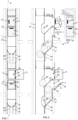
- Fig. 1 is a simplified diagram illustrating part of one apparatus applying the invention.
- the apparatus has a mainly vertical material conveying channel 1, such as a feeding chute, which may comprise at least one input station.
- the input station may have several input points 2, 3, and from each of them there may be a feed aperture 20, 30 for feeding material w1, w2, w3 from the feed aperture 20, 30 into a channel space 10 of the mainly vertical material conveying channel 1.
- An openable and closable hatch 21, 31 or the like may be provided in connection with each of the input points 2,3, as illustrated in the embodiment of Fig. 1 and 2 , which hatch in the closed state blocks the connection from the outside of the input point via the feed aperture 20, 30 to the material conveying channel 1, to the channel space.
- a feed-in container 22, 32 via which the material is fed into the feed aperture 20, 30 of the material conveying channel.
- the hatch 21, 31 of the input point enables the feeding of material from the outside of the input point via the feed aperture 20, 30 into the channel space 10 of the material conveying channel 1 or at least into the feed-in container 22, 32 arranged in the input point.
- the input point may be provided with one stopper means 40 having at least two positions, a first position in which the stopper means 40 limits the passage of the material w via the feed aperture to the channel space 10 of the material conveying channel, and a second position in which the stopper means 40 does not essentially limit the passage of the material w via the feed aperture to the channel space 10 of the material conveying channel 1.
- the stopper means is arranged between the feed aperture of the feed-in container and the material conveying channel 10.
- the stopper means 40 may be arranged at the wall of the feed-in container so that the stopper means 40 extends in the first position over at least part of the passageway of material from the feed-in container to the material conveying channel.
- the stopper means 40 may be arranged to extend upwards to a distance from a base part 37 of the feed-in container, preventing the passage of material from the feed-in container 32 through the feed aperture 30 into the material space 10 of the material channel.
- a drive device 41 is arranged to move the stopper means 40.
- the drive device 41 is an actuator, for example an actuator providing a linear movement.
- One such actuator is for example a cylinder-piston unit, the stopper means being arrangeable in the piston thereof.
- the stopper means 40 may be for example a rod means, a fork or the like.
- at least two stopper means 40 are arranged in proximity to the applicable material channel feed apertures. The number may be smaller or larger depending for example on the material to be processed, the shape of the stopper means or other requirements of the application.
- the stopper means is arranged between a second input point 3 and the material conveying channel. Between a first input point 2 and the material conveying channel there is no stopper means in the embodiment of the figure.
- the stopper means are illustrated in the second position in which the stopper means does not limit the passage of material from the feed-in container 32 of the second input point 3 to the channel space 10 of the material conveying channel via the feed aperture 30.
- the stopper means 40 are illustrated in the first position in which they prevent material from passing from the feed-in container of the second input point to the material space 10 of the material conveying channel.
- a feed-in container 32 may thus be arranged in connection with an input point for storing material fed into the feed-in container via a feed aperture 36 of the feed-in container 32 before feeding material via the feed aperture 30 of the material conveying channel 1 into the channel space 10.
- several input points 2, 3 may be arranged in proximity to each other.
- two input points 2, 3 are arranged in proximity to each other.
- the input points 2,3 may be arranged in a vertical direction at a distance from each other.
- a first input point 2 is arranged higher and a second input point 3 is arranged below the first input point, at a distance from the first input point.
- a feed aperture 20 of the first input point 2 or a feed aperture 26 of the feed-in container 22 thereof is provided with a first hatch 21.
- a feed aperture of the feed-in container 32 of the second input point 3 is provided with a second hatch 31.
- the input points may also be in the opposite order, whereby the feed aperture of the first input point, or the feed aperture of the feed-in container thereof, is disposed below the feed aperture of the second input point or the feed aperture of the feed-in container thereof in the vertical direction.
- Fig. 5 illustrates one embodiment in which there is a third input point 5 disposed in the horizontal direction at a distance from the first and the second input points. This embodiment will be described in more detail hereinafter.
- Fig. 1, 2 and 1a thus illustrate an embodiment in which the feed aperture 20 of the first input point 2 or the feed aperture 26 of the feed-in container 22 of the first input point, and the feed aperture 30 of the second input point 3 or the feed aperture 36 of the feed-in container 32 of the second input point may be arranged for example in the vertical direction at a distance from each other.
- a feed channel connecting the feed aperture 26 of the feed-in container of the first input point 2 or the feed aperture 36 of the feed-in container of the second input point 3 by way of the feed channel via the feed aperture 20, 30 of the material conveying channel 1 to the channel space 10.
- stopper means 40 may be arranged in connection with the feed aperture 20, 30 of the material conveying channel 1 to limit the quantity or size of the material w to be fed and to prevent the feeding of material into the material conveying channel.
- Several input points 2, 3 and feed apertures 20, 30 and/or hatches 21, 31 of the input point may be arranged for the material conveying channel at a distance from each other, as in the embodiment of Fig. 1, 2 .
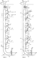
- the input points may be arranged in the vertical direction at a distance from each other, for example on different floors F1, F2, F3... Fn of a building or a vessel (for example as illustrated in Fig. 3-8 ).
- the input points 2, 3 are arranged in connection with a vertical wall P. The input points 2, 3 will be described in more detail hereinafter.
- the mainly vertical material conveying channel 1 such as a feeding chute, may be connected at the lower part of the material conveying channel 1 to a conveying pipe 200 of a pneumatic material conveying system.
- a curved channel part 130 is arranged between the material conveying channel 1 and the conveying pipe of the pneumatic material conveying system.
- a discharge valve 80 may be arranged between the curved channel part 130 and the material conveying pipe 200.
- the discharge valve 80 may comprise a shut-off means 81 and a drive device 82 thereof.
- the coupling between the material conveying channel 1 and the material conveying pipe 200 is in the embodiment of Fig. 3-8 arranged for example in a space located in the lower part of the building, such as in a basement B.
- the material may pass together with transport air to a reception point of the system, such as a waste station, in which the material to be transported, such as waste material or recyclable material, is separated from transport air and conveyed for further processing or to a shipping container.
- a reception point of the system such as a waste station
- the material to be transported such as waste material or recyclable material
- At least one stopper means 40 may be arranged between the feed aperture 26, 36 of the feed-in container of the first input point 2 and/or the second input point 3 and the material conveying channel 10, the stopper means having at least two positions, a first position in which the stopper means 40 limits the passage of the material w via the feed aperture 20, 30 to the channel space 10 of the material conveying channel, and a second position in which the stopper means 40 does not essentially limit the passage of the material w via the feed aperture 20, 30 to the channel space 10 of the material conveying channel 1.
- a base 27 of the feed-in container 22 of the first input point 2 may be formed to be inclined, whereby the base slopes from the direction of the feed aperture 26 of the feed-in container 22 towards the feed aperture 20 of the material conveying channel 1.
- the base 37 of the feed-in container 32 of the second input point 3 may be formed to be inclined, whereby the base slopes from the direction of the feed aperture 36 of the feed-in container 32 towards the feed aperture 30 of the material conveying channel 1.
- the feed aperture 26, 36 of each of the feed-in containers may be arranged in the vertical direction at a distance from the corresponding feed aperture 20, 30 leading to the material space of the material channel. Material may thereby be fed from the feed aperture 26, 36 of the feed-in container, and the material passes in the vertical direction to the lower feed aperture 20, 30 of the material space, preferably guided by the base 27, 37 inclined towards the feed aperture of the feed-in container.
- the hatch 21 which at least partly blocks in a first position (closed position) the aperture of the first input point 2 is arranged in a pivotable manner. In the embodiment of the figure, it is arranged to pivot about a vertical axis for example by means of hinges 24.
- the hatch may comprise opening means.
- a handle 25, 35 is depicted in the figures.
- the apparatus comprises closing means (not illustrated) for the hatch.
- the hatch 21, 31 may be released to open only when that is appropriate for the operation of the apparatus.
- different information means indicating the operating state of the apparatus may further be provided. The information means enable communication with the user and instructions for the operation of the user.
- light indicators L1, L2, L3 are illustrated as the information means.
- the information means or a display thereof may be arranged at the input point, for example in a panel above the first hatch, as illustrated in Fig. 1a.
- Fig. 1 and 2 illustrate the input points 2, 3 in the upper configuration of the figures with the hatch disposed in the first position, the closed position, and in the lower configuration of the figure with the hatch disposed in the second position, the opened position, in which the material may be fed to the input point, into the feed-in container thereof.
- Fig. 3-8 illustrate a first input point 2 and a second input point 3 on a first floor F1, and correspondingly a first input point 2 and a second input point 3 on a second floor F2.
- the figure also illustrates a first input point 2 and a second input point 3 on a highest floor Fn.
- An upper end of the material conveying channel 1 may extend for example higher than the input points of the highest floor Fn, for example through a roof R.
- the channel space 10 of the material conveying channel 1 is connected at an upper end 119 thereof to an air duct 121.
- a protective part 120 may be provided.
- the air duct is located on the roof of the building.
- a fan 155 and a drive device 156 thereof may be arranged for keeping the material conveying channel under a negative pressure and for ventilating it.
- the material conveying channel 1 extends through the structures separating different floors F1, F2, F3... Fn of the building.
- material may be fed, when at least the hatch 21 of at least one first input point 2 is in a state in which it may be opened, from the feed aperture 20 of the material conveying channel 1 of the first input point into the channel space 10.
- a first material fraction w1 is to be fed from the feed aperture of the first input point.
- the material fed passes in the channel space 10 to the lower part thereof, for example into the curved channel part 130.
- the material fed via the first input point may thus be stored temporarily in the lower part of the material conveying channel.
- a guide means 71 with which the material may be guided forward in the material conveying channel 1 or out from the channel space 10 of the material conveying channel 1, via an aperture or a connector 70 arranged at the wall of the channel.
- material fed from the first input point may be guided out from the lower part of the material conveying channel for example to a container 73 or the like via the aperture or connector 70, when the guide means 71 blocking the aperture or connector 70 in a first position is disposed in a second position in which the passageway from the material space 10 of the material conveying pipe to the outside thereof via the aperture or connector 70 is open.
- This configuration is illustrated for example in Fig. 9 .
- the guide means 71 may be for example a flap means configured to pivot about a joint 72 to a first position in which the passageway via the aperture or connector 70 from the channel space 10 of the material channel is closed, and a second position in which the passageway from the channel space of the material conveying channel via the aperture or connector 70 is open.
- the guide means may also be some other type of a passageway diverting means.
- a first material fraction w1 is arranged to be guided to the outside of the material conveying channel.
- the first material fraction may be in this case for example glass materials, such as glass bottles, glass jars or other glassware. Depending on the application, some other material fractions may also be conducted from the material conveying channel.
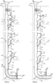
- material w2 may be fed into the storage space 32 provided in connection with at least one second input point.
- material may be fed into the feed-in container 32 of each of the second input points 3, even if the material conveying channel is simultaneously fed from the first input point 2 of some other input station, for example of a different floor.
- material w2 may be fed simultaneously into the feed-in containers 32 of the second input points 3 on different floors F1, F2 ... Fn and stored therein when the stopper means 40 arranged in connection with the feed aperture 30 between the feed-in container of the input point and the material conveying channel 1 is in the first position in which it prevents the passage of material from the feed-in container 32 to the channel space 10 of the material conveying channel 1.
- stopper means 40 arranged in connection with the feed aperture 30 between the feed-in container of the input point and the material conveying channel 1 is in the first position in which it prevents the passage of material from the feed-in container 32 to the channel space 10 of the material conveying channel 1.
- a first material w1 is fed into the feed-in container of the first input point 2 of the floor Fn from the feed aperture 26, which first material passes along the sloping base of the feed-in container to the channel space 10 of the material conveying channel 1 from the feed aperture 20 and further in the material conveying channel 1 to the lower part thereof, into a temporary storage which in the figure is in the curved channel part 130.
- the material is prevented from passing in the channel further by the shut-off means 81 of the discharge valve 80 of the material channel, which shut-off means separates the material conveying channel 1 from the conveying pipe 200 of the pneumatic conveying system.
- a second material fraction w2 may be fed into the feed-in container 32 of the second input point 3, wherein the stopper means 40 in the first position stops and prevents the material w2 from passing to the channel space of the material conveying channel via the feed aperture 30.
- the second material w2 is fed for example from the second input point 3 of the first floor F1 via the feed aperture 36 thereof into the feed-in container 32n and from the second input point 3 of the second floor F2.
- the feeding of material may be continued, for example as illustrated in Fig. 5 from the second input point of the floor Fn into the feed-in container thereof and into the second feed-in container of the floor F1.
- the first material is fed from the first input point 2 of the second floor, whereby it passes to the material channel and to the temporary storage space in the lower part thereof.
- a material quantity monitoring means 83 may be arranged in the apparatus to provide an impulse or information on the basis of which the first material w1 collected in the lower part of the channel space 1 may be discharged.
- the material quantity monitoring means 81 may be for example a limit switch or a means monitoring the level of the material quantity.
- the material collected in the material conveying channel may be discharged on the basis of the impulse of the material quantity monitoring means.
- the suction of the partial-vacuum generator of the pneumatic material conveying system is able to act from the direction of the material conveying piping 200 on the material w1, whereby the material passes due to the pressure difference and the transport air flow to the conveying piping in which it is transported to the container or separator arranged at the delivery end of the conveying piping, in which container or separator the material w1 is separated from the transport air flow.
- Replacement air to the material conveying channel may be conducted for example from a replacement air channel 60 which may be provided with a valve means, such as a flap arrangement.
- the replacement air channel 60 may be arranged at a connection point 61 between the material conveying channel 1 and the channel part.
- the discharge valve returns to the position in which the shut-off means 81 prevents material from passing from the channel space 10 of the material conveying channel to the conveying piping 200.
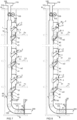
- Fig. 7 illustrates an operating state in which the second material fraction w2 stored in connection with the second input points 3, in the feed-in containers 32, is discharged.
- the material resting on the stopper means of the feed-in containers is released to pass to the channel space 10 of the material conveying channel 1 via the feed apertures 30 when the stopper means 40 is moved to the second position in which it does not prevent material from passing to the channel space 10.
- the feed-in containers of the second input points 3 are emptied in an order from the input point closest to the material conveying pipe 200, in Fig. 7 in an order from the bottom to the top.
- the material resting on the stopper means of different input points may be released at least partly simultaneously.
- the passageway to the conveying piping 200 may be opened by opening the shut-off means 81 of the valve 80 with the drive device 82.
- the suction of the partial-vacuum generator of the pneumatic material conveying system is able to act from the direction of the material conveying piping 200 on the material w2, whereby the material passes due to the pressure difference and the transport air flow to the conveying piping 200 in which it is transported in the transport air flow to the container or separator arranged at the delivery end of the conveying piping, in which container or separator the material w2 is separated from the transport air flow.
- the discharge valve returns to the position in which the shut-off means 81 prevents material from passing from the channel space 10 of the material conveying channel to the conveying piping 200.
- stopper means 40 may again be moved to the position in which they prevent material fed to the second input points, into the feed-in containers thereof, from passing to the channel space 1 of the material conveying channel. It is thus possible to again start the feeding of the first material and collecting it into the channel part 130 in the lower part of the material conveying channel.
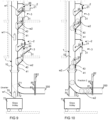
- Fig. 9 and 10 illustrate an alternative in which the first material fraction w1 is conveyed out from the channel space from the lower part of the material channel.
- a guide means 71 may have been arranged in the lower part of the material conveying channel 1, by which guide means the material may be guided forward in the material conveying channel 1 or out from the channel space 10 of the material conveying channel 1, via the aperture or connector 70 arranged at the wall of the channel.
- the material w1 fed from the first input point may be guided out from the lower part of the material conveying channel for example to a container 73 or the like via the aperture or connector 70, when the guide means 71 blocking the aperture or connector 70 in a first position is disposed in a second position in which the passageway from the material space 10 of the material conveying pipe to the outside thereof via the aperture or connector 70 is open.
- the guide means 71 may be for example a flap means configured to pivot about a joint 72 to a first position in which the passageway via the aperture or connector 70 from the channel space 10 of the material channel is closed, and a second position in which the passageway from the channel space of the material conveying channel via the aperture or connector 70 is open.
- the guide means may also be some other type of a passageway diverting means.
- the first material fraction w1 is arranged to be guided to the outside of the material conveying channel.
- the first material fraction may be in this case for example glass material, such as glass bottles, glass jars or other glassware.
- some other material fractions may also be conducted from the material conveying channel.
- the guide means 71 is pivoted to the position in which the passage from the material channel to the outside thereof via the aperture or connector 70 is closed and the material in the second feed-in containers 32 resting on the stopper means 40 is released to pass to the channel space of the material conveying channel via the feed apertures 30 and further to the lower part of the channel space of the material conveying channel, to the channel part 130.
- a transport air flow may again be provided to the conveying pipe and further to its delivery end.
- collecting the material may again begin according to Fig. 9 .
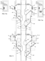
- Fig. 11 illustrates one further embodiment in which there is, in addition to the first input point 2 and the second input point 3 as illustrated above, also a third input point 5.
- the third input point is spaced from the first and the second input point.
- the third input point is arranged on a different side of the material conveying channel 1 in relation to the first and the second input points.
- a feed aperture 56 of a feed-in container 52 of the third input point is in the embodiment of the figure formed in the vertical direction at a height corresponding to the feed aperture 26 of the first input point 2. However, it may also be arranged at another height, considering e.g. application-specific requirements.
- the third input point 5 comprises a feed-in container 52, the base wall 57 of which is formed to be inclined so as to slope towards the feed aperture 50 leading to the channel space of the material channel.
- a stopper means 40 is arranged in a first position to prevent the passage of material from the feed-in container 52 of the third input point to the channel space of the material conveying channel via the feed aperture 50. In a second position the stopper means 40 does not prevent a third material fraction w3 from passing from the feed-in container 52 to the channel space 10 of the material conveying channel 1 via the feed aperture 50.
- the input station as illustrated in Fig. 11 , 11a, 11b enables the feeding of three material fractions in a sorted manner.
- the second material fraction w2 and the third material fraction w3 may be fed into the feed-in container 32, 52 of the input point 3, 5 of each of the material fractions from the feed aperture to be stored therein. Emptying of the feed-in containers of the second and the third input points may be carried out one material fraction at a time.
- the stopper means 40 are moved by the drive device 41 from the first position to the second position, i.e. the material w2, w3 resting on the stopper means 40 is released to pass, mainly by means of gravity and suction generated by the material conveying system, in the material conveying channel towards the conveying piping 200.
- the hatches 21 of the feed apertures are closed.
- the shut-off means 81 of the valve means 80 disposed between the conveying pipe 200 and the material conveying channel is opened by the drive device, whereby the suction generated by the partial-vacuum generator of the material conveying system, such as a pump or a fan, is able to act via the conveying pipe 200 on the material conveying channel 1.
- the channel part closest to the conveying pipe 200 is emptied, which channel part is the curved channel part 130 in the figure.
- the material w collected therein passes under the effect of suction to the conveying pipe 200.
- the feed-in containers of the input points connected to the channel space of the material conveying channel 1 are emptied in a controlled manner, one material fraction at a time, by acting on the stopper means 40 by the drive device 41 in an order from the bottom to the top in stages or floor by floor, by moving the stopper means 40 by the drive device 41 from the first position to the second position.
- a replacement air channel 60 provided with a valve means opening with suction, such as a flexible flap. This generates resistance, whereby the suction coming from the conveying pipe 200 acts on the vertical material conveying channel 1, on the channel space 10 thereof, and furthers the emptying thereof in addition to gravity.
- the stopper means 40 is arranged in the material conveying channel 1 or in the feed-in container connected thereto by connecting the frame of the stopper device or the drive device thereof to the material conveying channel 1 and/or to the structures of the feed-in container.
- the drive device 41 of the stopper means 40 may in one embodiment comprise a cylinder-piston unit.
- the stopper means 40 is arranged to move with the piston.
- the piston is moved by a medium conducted to the cylinder part 41, such as gas, for example compressed air, or fluid.
- the drive device 41 may also be another device, for example an electrically operated drive device.
- the stopper means 40 closes in the first position the connection to the material conveying channel 1 via the feed aperture completely.
- the stopper means 40 closes in the first position the connection to the material conveying channel via the feed aperture partly.
- the stopper means 40 is a plate part moved by the drive device 41.
- the stopper means 40 is a rod or pipe part moved by the drive device 41.
- the stopper means 40 is formed by several rod or pipe parts moved by the drive device.
- the stopper means 40 is formed by several rod or pipe parts moved by the drive device 41. In the figures, each of the rod or pipe means of the stopper means 40 have a respective drive device 41, but part of them or all of them may according to another embodiment be moved by a common drive device.
- the input point 2, 3, 5 may be arranged at a wall P.
- An aperture may be formed in the wall, the location and dimensions thereof corresponding to set requirements.
- the aperture of the wall P is arranged to be covered by a cover plate which may comprise switches, sensors and/or control means and/or information means L1, L2, L3.
- the hatch of the input point may be automatic or manually openable and closable.
- a possible reader device such as an RFID reader, may also be disposed in connection with the hatch.
- Fig. 12, 13 and 13a illustrate one further embodiment of an input station 90 in which the first input point 2 and the second input point 3 are arranged inside a jacket 91 arranged at the upper end of the material conveying channel 1.
- the jacket 91 is arranged at a lower part thereof on a mounting surface s, such as floor, or on the ground surface.
- the jacket 91 forms a sidewall of the input station.
- the input station has an upper wall 92, i.e. a roof. In the embodiment of the figure the roof may have been formed to be inclined, but it may also have another shape.
- An aperture is arranged in the jacket 91 for the feed apertures 26, 36 of the feed-in containers 22, 32.
- the input station is provided with hatches 21, 31 at least partly covering the respective feed apertures in the first position.
- the jacket or another point of the input station may be provided with information means L1, L2, L3 to indicate the state of the input station or to instruct the user.
- the input station as illustrated in Fig. 12-13 may be applied for example as aboveground input points in a pneumatic waste conveying system. There may be several input stations side by side, spaced from each other. The input points 2, 3 have been described in more detail hereinabove.
- the idea in the input station illustrated in Fig. 12 and 13 is that materials of two or more material fractions may be fed into the same input station 90.
- the material conveying channel 1 extends through the structures separating different floors F1, F2, F3... Fn of the building.
- the material conveying channel 1 is provided with means for conducting replacement air to the channel space 10 of the material conveying channel 1 at least when conveying material from the channel part of the material conveying channel to the conveying pipe 200 and further to the delivery end of the material conveying system.
- the invention thus relates to a method for feeding and conveying material in a sorted manner in a pneumatic material conveying system, in which method at least two material fractions w1, w2 are fed via at least two input points 2, 3 into a channel space 10 of a material conveying channel 1 from a feed aperture and conveyed in the channel space further to a delivery end of the material conveying channel mainly by means of gravity and/or suction generated by a partial-vacuum generator of the pneumatic material conveying system.
- Material is fed from at least one feed aperture of at least one input point 2, 3 and a first material fraction w1 fed via at least one first input point 2, 3 is conducted to the channel space 10 of the material conveying channel 1 and stored temporarily in the channel space 1 or conducted from the channel space to the outside of the channel space, and material is fed into a feed-in container 32 of at least one second input point 3, in which feed-in container a second material fraction w2 fed therein is held in temporary storage by a stopper means 40, which stopper means 40 prevents the passage of the material fraction w2 in a first operating state from the second feed-in container 32 to the channel space 1 of the material conveying channel.
- the first material fraction w1 fed into the channel space 10 of the material conveying channel 1 and stored temporarily therein is conveyed in a material conveying pipe 200 of the pneumatic material conveying system to a separator device or container in which the material fraction is separated from transport air.
- the material fraction w2 stored temporarily in the feed-in container 32 of at least one second input point 3 is released by moving the stopper means 40 to a second position in which the stopper means 40 does not prevent the passage of material to the channel space 10 of the material conveying channel 1, whereby the material fraction w2 may pass from the feed-in container 32 to the channel space of the material conveying channel via a feed aperture 30.
- materials or different material fractions are fed simultaneously into feed-in containers of different input points 2, 3.
- feed-in containers 22, 32 of a first input point 2 and a second input point 3 are disposed in proximity to each other, preferably in a vertical direction one on top of the other or in a horizontal direction side by side.
- the first material fraction w1 is guided from the channel space by opening a passageway 71 to the outside of the channel space by a guide means 71.
- a material feed aperture 26 to the feed-in container 22 of the first input point is openable and closable by a first hatch 21.
- a material feed aperture 36 to the feed-in container 32 of the second input point is openable and closable by a second hatch 31.
- a third material fraction w3 is fed to at least one third input point 5, into a feed-in container 52 thereof, in which feed-in container the third material fraction w3 fed therein is held in temporary storage by a stopper means 40, which stopper means 40 prevents the passage of the material fraction w3 in a first operating state from the second feed-in container 32 to the channel space 1 of the material conveying channel.
- the material fraction w3 stored temporarily in the feed-in container 52 of at least one third input point 5 is discharged by releasing it, by moving the stopper means 40 to a second position in which the stopper means 40 does not prevent the passage of material to the channel space 10 of the material conveying channel 1, whereby the material fraction w3 may pass from the feed-in container 32 to the channel space of the material conveying channel via a feed aperture 30.
- the material fraction w1, w2, w3 conveyed to the channel space 10 of the material conveying channel 1 is conveyed in the material conveying pipe 200 of the pneumatic material conveying system by means of a pressure difference generated by the partial-vacuum generator of the pneumatic material conveying system and/or a transport air flow to the separator device or container in which the material fraction is separated from transport air.
- the material fraction w to be conveyed in the method is waste material, such as waste material packed into bags, or recyclable material, or one or more of the following: glass, plastic, paper, paperboard, organic material, biomaterial, mixed waste.
- replacement air is introduced in the method at least in the conveying stage to an opposite side in relation to the conveying direction of a material batch collected in the channel space 10 of the material conveying channel 1.
- the method is used in buildings or vessels to convey waste material or recyclable material.
- part of the channel space of the material conveying channel is arranged to extend in a direction different from the vertical direction.
- the invention also relates to an apparatus for feeding and conveying material in a sorted manner in a pneumatic material conveying system, which apparatus comprises at least two input points 2, 3 for feeding at least two material fractions w1, w2 via a feed-in container 22, 32 of the input point 2, 3 into a channel space 10 of a material conveying channel 1 from a feed aperture 20, 30 and conveying them in the channel space further to a delivery end of the material conveying channel mainly by means of gravity and/or suction generated by a partial-vacuum generator of the pneumatic material conveying system.
- the apparatus comprises at least one feed aperture of the input point 2, 3 and a passageway from the feed aperture 26, 36 of the input point of the feed-in container 22, 32 to the channel space 10 of the material channel 1 from the feed aperture 20, 30, and that the passageway from the feed-in container 22 of a first input point 2 to the channel space 10 of the material channel 1 is open, and that in connection with at least a second feed-in container 32 and the channel space 10 of the material channel a stopper means 40 is arranged, which stopper means 40 prevents in a first operating state the passage of a material fraction from the second feed-in container 32 to the channel space 1 of the material conveying channel and in a second operating state releases the material fraction to pass from the second feed-in container 32 to the channel space 10 of the material conveying channel, whereby the second feed-in container is arranged to be used as a temporary storage for material in the first position of the stopper means, and that a channel part of the material conveying channel is provided with means for temporarily storing material fed into the channel or with guide means for conducting material
- feed-in containers 22, 32 of a first input point 2 and a second input point 3 are disposed in proximity to each other, preferably in a vertical direction one on top of the other or in a horizontal direction side by side.
- a guide means 71 is arranged for guiding a material fraction w1 from the channel space for opening a passageway 70 to the outside of the channel space by the guide means 71 in a first position thereof and for closing the passageway 70 to the outside of the channel space in a second position of the guide means 71.
- a material feed aperture 26 to the feed-in container 22 of the first input point is openable and closable by a first hatch 21 which is preferably hinged to open and close about a vertical axis.
- a material feed aperture 36 to the feed-in container 32 of the second input point is openable and closable by a second hatch 31 which is preferably of a hopper type and hinged to open and close about a horizontal axis.
- the stopper means 40 is a plate or rod or pipe part moved by a drive device 41.
- the material conveying channel 1 is provided with several spaced-apart input stations formed by at least two input points 2, 3.
- the stopper means 40 of the feed-in container 32 of at least the second input point are arranged to move from a first position to a second position in stages, starting from the lowest stopper means 40 disposed in the first position and moving from each previous stopper means to the next lowest one, until all stopper means of the material conveying channel 1 have been moved from the first position to the second position.
- the apparatus comprises means 60, 61 for conducting replacement air to the channel space 10 of the material channel 1.
- the apparatus is arranged in a building or a vessel to be applied in conveying waste material or recyclable material.
- the material fractions may be waste material or recyclable material, such as waste material arranged into bags, recyclable articles, bottles, containers, metal, plastic, paper, paperboard, mixed waste, organic waste, biowaste, etc.
Landscapes
- Engineering & Computer Science (AREA)
- Mechanical Engineering (AREA)
- Physics & Mathematics (AREA)
- Fluid Mechanics (AREA)
- Refuse Collection And Transfer (AREA)
- Air Transport Of Granular Materials (AREA)
- Branching, Merging, And Special Transfer Between Conveyors (AREA)
Claims (25)
- Vorrichtung zum Zuführen und Fördern von Material in sortierter Weise in einem pneumatischen Materialfördersystem, wobei die Vorrichtung mindestens zwei Eingabepunkte (2, 3) zum Zuführen von mindestens zwei Materialfraktionen (w1, w2) über einen Zuführbehälter (22, 32) des Eingabepunkts (2, 3) in einen Kanalraum (10) eines Materialförderkanals (1) von einer ersten Zuführapertur (20, 30) und zum Weiterfördern derselben in dem Kanalraum zu einem Ablieferungsende des Materialförderkanals hauptsächlich mittels Schwerkraft und/oder Ansaugung, die durch einen Teilvakuumerzeuger des pneumatischen Materialfördersystems erzeugt wird, umfasst,wobei eine erste Zuführapertur (20) des ersten Eingabepunkts (2) und eine erste Zuführapertur (30) des zweiten Eingabepunkts (3) in einer vertikalen Entfernung in einer Entfernung voneinander eingerichtet sind,wobei die Vorrichtung mindestens eine zweite Zuführapertur (26, 36) des Eingabepunkts (2, 3) und einen Durchgangsweg von der mindestens einen zweiten Zuführapertur (26, 36) des Eingabepunkts zum Kanalraum (10) des Materialförderkanals (1) umfasst, und der Durchgangsweg vom Zuführbehälter (22) eines ersten Eingabepunkts (2) zum Kanalraum (10) des Materialkanals (1) offen ist, undwobei in Verbindung mit mindestens einem zweiten Zuführbehälter (32) und dem Kanalraum (10) des Materialkanals ein Verschlussmittel (40) eingerichtet ist, welches Verschlussmittel (40) in einem ersten Betriebszustand den Durchgang einer Materialfraktion von dem zweiten Zuführbehälter (32) zu dem Kanalraum (1) des Materialförderkanals verhindert und in einem zweiten Betriebszustand die Materialfraktion für den Durchgang vom zweiten Zuführbehälter (32) zum Kanalraum (10) des Materialförderkanals freigibt, wobei der zweite Zuführbehälter (32) dazu eingerichtet ist, als temporärer Speicher für Material in der ersten Position des Verschlussmittels (40) verwendet zu werden, dadurch gekennzeichnet, dass ein Kanalteil des Materialförderkanals (1) mit Mitteln zum temporären Speichern von in den Kanal zugeführtem Material versehen ist, und dadurch, dass Zuführbehälter (22, 32) eines ersten Eingabepunkts (2) und eines zweiten Eingabepunkts (3) in der Nähe zueinander, in einer vertikalen Richtung einer über dem anderen, angeordnet sind.
- Vorrichtung gemäß Anspruch 1, dadurch gekennzeichnet, dass der Kanalteil des Materialförderkanals mit Leitmitteln zum Durchleiten von Material zur Außenseite des Kanalraums bereitgestellt ist.
- Vorrichtung gemäß Anspruch 1 oder 2, dadurch gekennzeichnet, dass im Kanalraum des Materialförderkanals ein Leitmittel (71) dazu eingerichtet ist, eine Materialfraktion (w1) vom Kanalraum zum Öffnen eines Durchgangwegs (70) zur Außenseite des Kanalraums durch das Leitmittel (71) in einer ersten Position desselben und zum Schließen des Durchgangwegs (70) zur Außenseite des Kanalraums in einer zweiten Position des Leitmittels (71) zu leiten.
- Vorrichtung gemäß Anspruch 1 oder 3, dadurch gekennzeichnet, dass die zweite Zuführapertur (26) zum Zuführbehälter (22) des ersten Eingabepunkts öffnungsfähig und schließfähig ist durch eine erste Klappe (21), die vorzugsweise zum Öffnen und Schließen um eine vertikale Achse schwenkbar ist.
- Vorrichtung gemäß einem der Ansprüche 1 - 4, dadurch gekennzeichnet, dass die zweite Zuführapertur (36) zum Zuführbehälter (32) des zweiten Eingabepunkts öffnungsfähig und schließfähig ist durch eine zweite Klappe (31), die vorzugsweise trichterförmig ist und zum Öffnen und Schließen um eine horizontale Achse schwenkbar ist.
- Vorrichtung gemäß einem der Ansprüche 1 - 5, dadurch gekennzeichnet, dass das Verschlussmittel (40) eine Platte oder Stab oder Rohrteil ist, das durch ein Antriebsgerät (41) bewegt wird.
- Vorrichtung gemäß einem der Ansprüche 1 - 6, dadurch gekennzeichnet, dass der Materialförderkanal (1) mit mehreren beabstandeten Eingabestationen versehen ist, die durch mindestens zwei Eingabepunkte (2, 3) gebildet werden.
- Vorrichtung gemäß einem der Ansprüche 1 - 7, dadurch gekennzeichnet, dass die Verschlussmittel (40) des Zuführbehälters (32) von mindestens dem zweiten Eingabepunkt dazu eingerichtet sind, sich von einer ersten Position zu einer zweiten Position in Etappen zu bewegen, beginnend mit dem untersten Verschlussmittel (40), das in der ersten Position angeordnet ist, und sich von jedem vorherigen Verschlussmittel zum nächstuntersten bewegt, bis alle Verschlussmittel des Materialförderkanals (1) von der ersten Position in die zweite Position bewegt worden sind.
- Vorrichtung gemäß einem der Ansprüche 1 - 8, dadurch gekennzeichnet, dass die Vorrichtung Mittel (60, 61) zum Durchleiten von Ersatzluft in den Kanalraum (10) des Materialkanals (1) umfasst.
- Vorrichtung gemäß einem der Ansprüche 1 - 9, dadurch gekennzeichnet, dass die Vorrichtung in einem Gebäude oder einem Gefäß eingerichtet ist, um zum Fördern von Abfallmaterial oder recyclingfähigem Material angewendet zu werden.
- Verfahren zum Zuführen und Fördern von Material in sortierter Weise in einem pneumatischen Materialfördersystem, das eine Vorrichtung gemäß Anspruch 1 umfasst, wobei bei dem Verfahren mindestens zwei Materialfraktionen (w1, w2) über mindestens zwei Eingabepunkte (2, 3) in einen Kanalraum (10 ) eines Materialförderkanals (1) von einer ersten Zuführapertur (20, 30) zugeführt werden und in dem Kanalraum zu einem Ablieferungsende des Materialförderkanals hauptsächlich mittels Schwerkraft und/oder Ansaugung, die durch einen Teilvakuumerzeuger des pneumatischen Materialfördersystems erzeugt wird, weitergefördert werden,wobei Material von mindestens einer ersten Zuführapertur (20, 30) von mindestens einem Eingabepunkt (2, 3) zugeführt wird und eine erste Materialfraktion (w1), die über mindestens einen ersten Eingabepunkt (2, 3) zugeführt wird, zum Kanalraum (10) des Materialförderkanals (1) durchgeleitet und in einem temporären Speicherraum (130) temporär gespeichert wird, und Material in einen Zuführbehälter (32) von mindestens einem zweiten Eingabepunkt (3) zugeführt wird, in welchem Zuführbehälter eine zweite Materialfraktion (w2), die darin zugeführt wird, durch ein Verschlussmittel (40) temporär gespeichert wird, welches Verschlussmittel (40) den Durchgang der Materialfraktion (w2) in einem ersten Betriebszustand von dem zweiten Zuführbehälter (32) zu dem Kanalraum (1) des Materialförderkanals verhindert, undwobei eine erste Zuführapertur (20) des ersten Eingabepunktes (2) und eine erste Zuführapertur (30) des zweiten Eingabepunktes (3) in einer vertikalen Entfernung in einer Entfernung voneinander eingerichtet sind, und Zuführbehälter (22, 32) eines ersten Eingabepunktes (2) und eines zweiten Eingabepunktes (3) in der Nähe zueinander, in einer vertikalen Richtung einer über dem anderen, angeordnet sind.
- Verfahren gemäß Anspruch 11, dadurch gekennzeichnet, dass die erste Materialfraktion (w1) mit Leitmitteln vom Kanalraum zur Außenseite des Kanalraums durchgeleitet wird.
- Verfahren gemäß Anspruch 11 oder 12, dadurch gekennzeichnet, dass in einer zweiten Etappe die erste Materialfraktion (w1), die in den Kanalraum (10) des Materialförderkanals (1) zugeführt und darin temporär gespeichert wird, in einem Materialförderrohr (200) des pneumatischen Materialfördersystems zu einem Abscheidegerät oder -behälter gefördert wird, in dem die Materialfraktion von der Transportluft abgeschieden wird.
- Verfahren gemäß Anspruch 11, 12 oder 13, dadurch gekennzeichnet, dass in einer dritten Etappe die Materialfraktion (w2), die temporär im Zuführbehälter (32) von mindestens einem zweiten Eingabepunkt (3) gespeichert ist, durch Bewegen des Verschlussmittels (40) in eine zweite Position freigegeben wird, in der das Verschlussmittel (40) den Durchgang von Material zum Kanalraum (10) des Materialförderkanals (1) nicht verhindert, wodurch die Materialfraktion (w2) von dem Zuführbehälter (32) zu dem Kanalraum des Materialförderkanals über eine Zuführapertur (30) durchgehen kann.
- Verfahren gemäß einem der Ansprüche 11-14, dadurch gekennzeichnet, dass Materialien oder unterschiedliche Materialfraktionen gleichzeitig in Zuführbehälter unterschiedlicher Eingabepunkte (2, 3) zugeführt werden.
- Verfahren gemäß einem der Ansprüche 11 - 15, dadurch gekennzeichnet, dass die erste Materialfraktion (w1) aus dem Kanalraum durch Öffnen eines Durchgangswegs (70) zur Außenseite des Kanalraums durch ein Leitmittel (71) geleitet wird.
- Verfahren gemäß einem der Ansprüche 11 - 16, dadurch gekennzeichnet, dass die zweite Zuführapertur (26) zum Zuführbehälter (22) des ersten Eingabepunkts öffnungsfähig und schließfähig ist durch eine erste Klappe (21).
- Verfahren gemäß einem der Ansprüche 11 - 17, dadurch gekennzeichnet, dass die zweite Zuführapertur (36) zum Zuführbehälter (32) des zweiten Eingabepunkts öffnungsfähig und schließfähig ist durch eine zweite Klappe (31).
- Verfahren gemäß einem der Ansprüche 11 - 18, dadurch gekennzeichnet, dass in dem Verfahren eine dritte Materialfraktion (w3) mindestens einem dritten Eingabepunkt (5) zugeführt wird, in einen Zuführbehälter (52) davon, in welchem Zuführbehälter die dritte Materialfraktion (w3 ), die darin zugeführt ist, durch ein Verschlussmittel (40) in temporärer Speicherung gehalten wird, welches Verschlussmittel (40) den Durchgang der Materialfraktion (w3) in einem ersten Betriebszustand von dem zweiten Zuführbehälter (32) zu dem Kanalraum (1) des Materialförderkanals verhindert.
- Verfahren gemäß Anspruch 19, dadurch gekennzeichnet, dass die Materialfraktion (w3), die temporär im Zuführbehälter (52) von mindestens einem dritten Eingabepunkt (5) gespeichert ist, durch Freigeben derselben abgeführt wird, indem das Verschlussmittel (40) in eine zweite Position bewegt wird, in der das Verschlussmittel (40) den Durchgang von Material zum Kanalraum (10) des Materialförderkanals (1) nicht verhindert, wodurch die Materialfraktion (w3) vom Zuführbehälter (32) zum Kanalraum des Materialförderkanals über eine erste Zuführapertur (30) durchgehen kann.
- Verfahren gemäß einem der Ansprüche 11 - 20, dadurch gekennzeichnet, dass die Materialfraktion (w1, w2, w3), die zum Kanalraum (10) des Materialförderkanals (1) gefördert wird, in dem Materialförderrohr (200) des pneumatischen Materialfördersystems mittels eines Druckunterschieds gefördert wird, der durch den Teilvakuumerzeuger des pneumatischen Materialfördersystems und/oder eine Transportluftströmung zu dem Abscheidegerät oder - behälter, in dem die Materialfraktion von der Transportluft getrennt wird, erzeugt wird.
- Verfahren gemäß einem der Ansprüche 11 - 21, dadurch gekennzeichnet, dass die Materialfraktion (w), die in dem Verfahren gefördert wird, Abfallmaterial ist, wie beispielsweise in Säcken verpacktes Abfallmaterial oder recyclingfähiges Material oder eines oder mehrere der Folgenden: Glas, Kunststoff, Papier, Pappe, organisches Material, Biomaterial, Mischabfall.
- Verfahren gemäß einem der Ansprüche 11 - 22, dadurch gekennzeichnet, dass Ersatzluft in dem Verfahren zumindest in der Förderetappe zu einer gegenüberliegenden Seite in Bezug auf die Förderrichtung einer Materialcharge, die in dem Kanalraum (10) des Materialförderkanals (1) gesammelt wird, eingeführt wird.
- Verfahren gemäß einem der Ansprüche 11 - 23, dadurch gekennzeichnet, dass das Verfahren in Gebäuden oder Gefäßen zum Fördern von Abfallmaterial oder recyclingfähigem Material verwendet wird.
- Verfahren gemäß einem der Ansprüche 11 - 24, dadurch gekennzeichnet, dass ein Teil des Kanalraums des Materialförderkanals dazu eingerichtet ist, sich in einer Richtung zu erstrecken, die von der vertikalen Richtung verschieden ist.
Applications Claiming Priority (2)
| Application Number | Priority Date | Filing Date | Title |
|---|---|---|---|
| FI20197011A FI20197011A1 (fi) | 2019-01-25 | 2019-01-25 | Menetelmä ja laitteisto materiaalin syöttämiseksi ja siirtämiseksi |
| PCT/FI2020/050022 WO2020152396A1 (en) | 2019-01-25 | 2020-01-13 | Method and apparatus for feeding and conveying material |
Publications (4)
| Publication Number | Publication Date |
|---|---|
| EP3914539A1 EP3914539A1 (de) | 2021-12-01 |
| EP3914539A4 EP3914539A4 (de) | 2022-11-09 |
| EP3914539C0 EP3914539C0 (de) | 2024-11-20 |
| EP3914539B1 true EP3914539B1 (de) | 2024-11-20 |
Family
ID=71736215
Family Applications (1)
| Application Number | Title | Priority Date | Filing Date |
|---|---|---|---|
| EP20744462.1A Active EP3914539B1 (de) | 2019-01-25 | 2020-01-13 | Verfahren und vorrichtung zum zuführen und fördern von material |
Country Status (12)
| Country | Link |
|---|---|
| US (1) | US11577912B2 (de) |
| EP (1) | EP3914539B1 (de) |
| JP (1) | JP7528094B2 (de) |
| KR (1) | KR102865273B1 (de) |
| CN (1) | CN113348139A (de) |
| AU (1) | AU2020211366B2 (de) |
| CA (1) | CA3125550A1 (de) |
| ES (1) | ES3014282T3 (de) |
| FI (1) | FI20197011A1 (de) |
| PL (1) | PL3914539T3 (de) |
| SA (1) | SA521422600B1 (de) |
| WO (1) | WO2020152396A1 (de) |
Families Citing this family (3)
| Publication number | Priority date | Publication date | Assignee | Title |
|---|---|---|---|---|
| FI20215466A1 (en) * | 2021-04-21 | 2022-10-22 | Maricap Oy | Requesting and directing access to waste collection points |
| CN115231165B (zh) * | 2022-03-15 | 2023-08-08 | 中冶南方城市建设工程技术有限公司 | 一种应用于智慧园区的智能垃圾投放及计费控制系统 |
| FI131275B1 (en) * | 2023-12-20 | 2025-01-22 | Maricap Oy | PNEUMATIC MATERIAL TRANSPORT SYSTEM AND PROCEDURE |
Family Cites Families (34)
| Publication number | Priority date | Publication date | Assignee | Title |
|---|---|---|---|---|
| GB1199917A (en) * | 1966-07-29 | 1970-07-22 | Centralsug Ab | Conveyance of Material Requiring Hygienic Disposal |
| SE371409B (de) * | 1972-08-25 | 1974-11-18 | Svenska Flaektfabriken Ab | |
| SE403753B (sv) * | 1974-01-31 | 1978-09-04 | Svenska Flaektfabriken Ab | Anleggning for sortering av minst tva skilda godsslag |
| US3986590A (en) * | 1975-05-06 | 1976-10-19 | Lapidus Berton M | Container delivery apparatus |
| US4076321A (en) * | 1976-12-06 | 1978-02-28 | Eastern Cyclone Industries, Inc. | Electronic control system for operating a pneumatic trash linen conveying network |
| EP0297145A4 (de) * | 1986-12-22 | 1990-03-27 | Shimizu Construction Co Ltd | Verfahren und system zum sammeln von müll. |
| US4902482A (en) * | 1987-07-28 | 1990-02-20 | Faust Paul A | Device and receptacle for inhibiting contamination for infections waste |
| CA2013984A1 (en) * | 1990-04-05 | 1991-10-05 | Geoffrey B. Sims | Waste disposal chute |
| JPH0680202A (ja) * | 1991-07-01 | 1994-03-22 | Fujita Corp | ごみ仕分け搬出システム |
| US5213402A (en) * | 1991-11-01 | 1993-05-25 | Joseph Bernal | Recycling cabinet unit |
| US5280688A (en) * | 1992-02-14 | 1994-01-25 | Zoccoli Richard S | Recycling apparatus |
| JP2000507904A (ja) * | 1995-11-02 | 2000-06-27 | ファブリク ド タバ リュニエ ソシエテ アノニム | 空気圧コンベアシステムのためのインターチェンジ |
| FR2807083A1 (fr) | 2000-04-03 | 2001-10-05 | Hortig T C Air | Installation d'evacuation des dechets menagers dans les immeubles |
| FI123765B (fi) | 2007-12-21 | 2013-10-31 | Maricap Oy | Menetelmä pneumattisessa materiaalinsiirtojärjestelmässä ja pneumaattinen materiaalinsiirtojärjestelmä |
| FI20085146A7 (fi) | 2007-12-21 | 2009-06-22 | Maricap Oy | Menetelmä ja laitteisto pneumaattisessa materiaalinsiirtojärjestelmässä |
| US20100296880A1 (en) | 2007-12-21 | 2010-11-25 | Sundholm Goeran | Pneumatic material conveying system |
| FI123782B (fi) | 2007-12-21 | 2013-10-31 | Maricap Oy | Menetelmä ja laitteisto pneumaattisessa materiaalinsiirtojärjestelmässä |
| FI20085145L (fi) | 2007-12-21 | 2009-06-22 | Maricap Oy | Menetelmä ja laitteisto pneumaattisessa materiaalinsiirtojärjestelmässä |
| FI20085149A7 (fi) | 2007-12-21 | 2009-06-22 | Maricap Oy | Menetelmä ja laitteisto pneumaattisessa materiaalinsiirtojärjestelmässä |
| FI124507B (fi) | 2007-12-21 | 2014-09-30 | Maricap Oy | Menetelmä pneumaattisessa materiaalinsiirtojärjestelmässä ja pneumaattinen materiaalinsiirtojärjestelmä |
| FI20085143L (fi) | 2007-12-21 | 2009-06-22 | Maricap Oy | Menetelmä ja laitteisto pneumaattisessa materiaalinsiirtojärjestelmässä |
| FI124408B (fi) | 2007-12-21 | 2014-08-15 | Maricap Oy | Menetelmä ja laitteisto pneumaattisessa materiaalinsiirtojärjestelmässä |
| AU2008365343B2 (en) * | 2008-12-18 | 2013-11-21 | Premium Patents Sdn. Bhd | Method and system for pushing and moving solid waste |
| KR100916033B1 (ko) * | 2009-03-24 | 2009-09-08 | 코오롱건설주식회사 | 쓰레기 수거 시스템 및 쓰레기 수거 시스템의 쓰레기 투입구 개폐 방법 |
| FI20095897A7 (fi) * | 2009-09-01 | 2011-03-02 | Maricap Oy | Menetelmä ja laitteisto jätekuilussa |
| FI122103B (fi) | 2010-03-12 | 2011-08-31 | Maricap Oy | Menetelmä ja laitteisto pneumaattisessa materiaalinsiirtojärjestelmässä ja jätteensiirtojärjestelmä |
| CN103189285B (zh) * | 2010-06-23 | 2016-03-30 | 恩华特公司 | 真空废物收集系统及其操作方法 |
| FI124335B (fi) | 2012-09-26 | 2014-07-15 | Maricap Oy | Laite virtaustien vaihtamiseksi ja materiaalin keräily- ja siirtojärjestelmä |
| FI124837B (fi) * | 2013-07-30 | 2015-02-13 | Maricap Oy | Menetelmä ja laitteisto jätemateriaalin syöttämiseksi ja käsittelemiseksi |
| WO2015140403A1 (en) | 2014-03-17 | 2015-09-24 | Maricap Oy | Method and apparatus for feeding in and conveying material |
| WO2016054508A1 (en) * | 2014-10-02 | 2016-04-07 | Precision Airconvey Corporation | Material handling system with queue chute |
| US9637324B2 (en) * | 2014-11-20 | 2017-05-02 | Peggy Adamick | Refuse disposing system |
| CN106429127A (zh) | 2016-12-23 | 2017-02-22 | 福建海山机械股份有限公司 | 封闭式垃圾自动收集系统 |
| US20210172629A1 (en) * | 2019-12-10 | 2021-06-10 | Eric Pollock | Methods and systems for managing airflow and contamination in loading stations and chutes of transport systems |
-
2019
- 2019-01-25 FI FI20197011A patent/FI20197011A1/fi unknown
-
2020
- 2020-01-13 KR KR1020217026059A patent/KR102865273B1/ko active Active
- 2020-01-13 CN CN202080010799.6A patent/CN113348139A/zh active Pending
- 2020-01-13 CA CA3125550A patent/CA3125550A1/en active Pending
- 2020-01-13 US US17/420,422 patent/US11577912B2/en active Active
- 2020-01-13 EP EP20744462.1A patent/EP3914539B1/de active Active
- 2020-01-13 WO PCT/FI2020/050022 patent/WO2020152396A1/en not_active Ceased
- 2020-01-13 JP JP2021540900A patent/JP7528094B2/ja active Active
- 2020-01-13 PL PL20744462.1T patent/PL3914539T3/pl unknown
- 2020-01-13 AU AU2020211366A patent/AU2020211366B2/en active Active
- 2020-01-13 ES ES20744462T patent/ES3014282T3/es active Active
-
2021
- 2021-07-24 SA SA521422600A patent/SA521422600B1/ar unknown
Also Published As
| Publication number | Publication date |
|---|---|
| SA521422600B1 (ar) | 2023-10-24 |
| EP3914539C0 (de) | 2024-11-20 |
| JP7528094B2 (ja) | 2024-08-05 |
| WO2020152396A1 (en) | 2020-07-30 |
| ES3014282T3 (en) | 2025-04-21 |
| AU2020211366B2 (en) | 2025-08-14 |
| AU2020211366A1 (en) | 2021-08-12 |
| CA3125550A1 (en) | 2020-07-30 |
| US11577912B2 (en) | 2023-02-14 |
| CN113348139A (zh) | 2021-09-03 |
| KR102865273B1 (ko) | 2025-09-26 |
| KR20210119442A (ko) | 2021-10-05 |
| JP2022523458A (ja) | 2022-04-25 |
| EP3914539A1 (de) | 2021-12-01 |
| FI20197011A1 (fi) | 2020-07-26 |
| EP3914539A4 (de) | 2022-11-09 |
| US20220081206A1 (en) | 2022-03-17 |
| PL3914539T3 (pl) | 2025-03-31 |
Similar Documents
| Publication | Publication Date | Title |
|---|---|---|
| EP3914539B1 (de) | Verfahren und vorrichtung zum zuführen und fördern von material | |
| KR102242806B1 (ko) | 폐기물을 공급 및 취급하기 위한 방법과 장치 | |
| US12378085B2 (en) | Method for conveying material and material conveying arrangement | |
| CA2917371C (en) | Method and apparatus for feeding in and handling waste material | |
| WO2015140403A1 (en) | Method and apparatus for feeding in and conveying material | |
| US11498756B2 (en) | Method for handling material in a material conveying system, a separating device arrangement and a material conveying system | |
| EP3107839B1 (de) | Verfahren zur handhabung eines materials in einem materialfördersystem, einsetzpunkt für ein materialfördersystem sowie materialfördersystem | |
| US20150274419A1 (en) | Method for handling material in a material conveying system, input point of a material conveying system, and a material conveying system | |
| RU2809748C2 (ru) | Способ и устройство для загрузки и транспортировки материала | |
| US11180315B2 (en) | Method in a feed-in station and input point arrangement | |
| WO2025133463A1 (en) | Pneumatic material conveying system and method | |
| RU2787909C2 (ru) | Способ на станции подачи и конструкция пунктов загрузки | |
| EP3074326B1 (de) | Verfahren zum einführen und handhaben eines materials, einführpunkt und abfallfördersystem |
Legal Events
| Date | Code | Title | Description |
|---|---|---|---|
| STAA | Information on the status of an ep patent application or granted ep patent |
Free format text: STATUS: THE INTERNATIONAL PUBLICATION HAS BEEN MADE |
|
| PUAI | Public reference made under article 153(3) epc to a published international application that has entered the european phase |
Free format text: ORIGINAL CODE: 0009012 |
|
| STAA | Information on the status of an ep patent application or granted ep patent |
Free format text: STATUS: REQUEST FOR EXAMINATION WAS MADE |
|
| 17P | Request for examination filed |
Effective date: 20210820 |
|
| AK | Designated contracting states |
Kind code of ref document: A1 Designated state(s): AL AT BE BG CH CY CZ DE DK EE ES FI FR GB GR HR HU IE IS IT LI LT LU LV MC MK MT NL NO PL PT RO RS SE SI SK SM TR |
|
| DAV | Request for validation of the european patent (deleted) | ||
| DAX | Request for extension of the european patent (deleted) | ||
| A4 | Supplementary search report drawn up and despatched |
Effective date: 20221011 |
|
| RIC1 | Information provided on ipc code assigned before grant |
Ipc: B65G 51/22 20060101ALI20221005BHEP Ipc: B65G 53/34 20060101ALI20221005BHEP Ipc: B65G 43/08 20060101ALI20221005BHEP Ipc: B65F 1/10 20060101ALI20221005BHEP Ipc: B65F 5/00 20060101AFI20221005BHEP |
|
| STAA | Information on the status of an ep patent application or granted ep patent |
Free format text: STATUS: EXAMINATION IS IN PROGRESS |
|
| 17Q | First examination report despatched |
Effective date: 20230829 |
|
| GRAP | Despatch of communication of intention to grant a patent |
Free format text: ORIGINAL CODE: EPIDOSNIGR1 |
|
| GRAP | Despatch of communication of intention to grant a patent |
Free format text: ORIGINAL CODE: EPIDOSNIGR1 |
|
| STAA | Information on the status of an ep patent application or granted ep patent |
Free format text: STATUS: GRANT OF PATENT IS INTENDED |
|
| INTG | Intention to grant announced |
Effective date: 20240614 |
|
| GRAS | Grant fee paid |
Free format text: ORIGINAL CODE: EPIDOSNIGR3 |
|
| GRAA | (expected) grant |
Free format text: ORIGINAL CODE: 0009210 |
|
| STAA | Information on the status of an ep patent application or granted ep patent |
Free format text: STATUS: THE PATENT HAS BEEN GRANTED |
|
| AK | Designated contracting states |
Kind code of ref document: B1 Designated state(s): AL AT BE BG CH CY CZ DE DK EE ES FI FR GB GR HR HU IE IS IT LI LT LU LV MC MK MT NL NO PL PT RO RS SE SI SK SM TR |
|
| REG | Reference to a national code |
Ref country code: GB Ref legal event code: FG4D |
|
| REG | Reference to a national code |
Ref country code: CH Ref legal event code: EP |
|
| REG | Reference to a national code |
Ref country code: DE Ref legal event code: R096 Ref document number: 602020041677 Country of ref document: DE |
|
| REG | Reference to a national code |
Ref country code: IE Ref legal event code: FG4D |
|
| U01 | Request for unitary effect filed |
Effective date: 20241209 |
|
| U07 | Unitary effect registered |
Designated state(s): AT BE BG DE DK EE FI FR IT LT LU LV MT NL PT RO SE SI Effective date: 20241219 |
|
| PG25 | Lapsed in a contracting state [announced via postgrant information from national office to epo] |
Ref country code: HR Free format text: LAPSE BECAUSE OF FAILURE TO SUBMIT A TRANSLATION OF THE DESCRIPTION OR TO PAY THE FEE WITHIN THE PRESCRIBED TIME-LIMIT Effective date: 20241120 Ref country code: IS Free format text: LAPSE BECAUSE OF FAILURE TO SUBMIT A TRANSLATION OF THE DESCRIPTION OR TO PAY THE FEE WITHIN THE PRESCRIBED TIME-LIMIT Effective date: 20250320 |
|
| PGFP | Annual fee paid to national office [announced via postgrant information from national office to epo] |
Ref country code: ES Payment date: 20250203 Year of fee payment: 6 |
|
| REG | Reference to a national code |
Ref country code: ES Ref legal event code: FG2A Ref document number: 3014282 Country of ref document: ES Kind code of ref document: T3 Effective date: 20250421 |
|
| PGFP | Annual fee paid to national office [announced via postgrant information from national office to epo] |
Ref country code: NO Payment date: 20250122 Year of fee payment: 6 |
|
| U20 | Renewal fee for the european patent with unitary effect paid |
Year of fee payment: 6 Effective date: 20250317 |
|
| PG25 | Lapsed in a contracting state [announced via postgrant information from national office to epo] |
Ref country code: GR Free format text: LAPSE BECAUSE OF FAILURE TO SUBMIT A TRANSLATION OF THE DESCRIPTION OR TO PAY THE FEE WITHIN THE PRESCRIBED TIME-LIMIT Effective date: 20250221 |
|
| PGFP | Annual fee paid to national office [announced via postgrant information from national office to epo] |
Ref country code: PL Payment date: 20250314 Year of fee payment: 6 |
|
| PGFP | Annual fee paid to national office [announced via postgrant information from national office to epo] |
Ref country code: GB Payment date: 20250123 Year of fee payment: 6 |
|
| PG25 | Lapsed in a contracting state [announced via postgrant information from national office to epo] |
Ref country code: RS Free format text: LAPSE BECAUSE OF FAILURE TO SUBMIT A TRANSLATION OF THE DESCRIPTION OR TO PAY THE FEE WITHIN THE PRESCRIBED TIME-LIMIT Effective date: 20250220 |
|
| PG25 | Lapsed in a contracting state [announced via postgrant information from national office to epo] |
Ref country code: SM Free format text: LAPSE BECAUSE OF FAILURE TO SUBMIT A TRANSLATION OF THE DESCRIPTION OR TO PAY THE FEE WITHIN THE PRESCRIBED TIME-LIMIT Effective date: 20241120 |
|
| PG25 | Lapsed in a contracting state [announced via postgrant information from national office to epo] |
Ref country code: SK Free format text: LAPSE BECAUSE OF FAILURE TO SUBMIT A TRANSLATION OF THE DESCRIPTION OR TO PAY THE FEE WITHIN THE PRESCRIBED TIME-LIMIT Effective date: 20241120 |
|
| PG25 | Lapsed in a contracting state [announced via postgrant information from national office to epo] |
Ref country code: CZ Free format text: LAPSE BECAUSE OF FAILURE TO SUBMIT A TRANSLATION OF THE DESCRIPTION OR TO PAY THE FEE WITHIN THE PRESCRIBED TIME-LIMIT Effective date: 20241120 |
|
| REG | Reference to a national code |
Ref country code: CH Ref legal event code: PL |
|
| PG25 | Lapsed in a contracting state [announced via postgrant information from national office to epo] |
Ref country code: MC Free format text: LAPSE BECAUSE OF FAILURE TO SUBMIT A TRANSLATION OF THE DESCRIPTION OR TO PAY THE FEE WITHIN THE PRESCRIBED TIME-LIMIT Effective date: 20241120 |
|
| PLBE | No opposition filed within time limit |
Free format text: ORIGINAL CODE: 0009261 |
|
| STAA | Information on the status of an ep patent application or granted ep patent |
Free format text: STATUS: NO OPPOSITION FILED WITHIN TIME LIMIT |
|
| PG25 | Lapsed in a contracting state [announced via postgrant information from national office to epo] |
Ref country code: CH Free format text: LAPSE BECAUSE OF NON-PAYMENT OF DUE FEES Effective date: 20250131 |
|
| 26N | No opposition filed |
Effective date: 20250821 |