EP3911378B1 - Verbessertes modulares verabreichungsgerät - Google Patents
Verbessertes modulares verabreichungsgerät Download PDFInfo
- Publication number
- EP3911378B1 EP3911378B1 EP19809626.5A EP19809626A EP3911378B1 EP 3911378 B1 EP3911378 B1 EP 3911378B1 EP 19809626 A EP19809626 A EP 19809626A EP 3911378 B1 EP3911378 B1 EP 3911378B1
- Authority
- EP
- European Patent Office
- Prior art keywords
- module
- reservoir
- contact arrangement
- contact
- reservoir module
- Prior art date
- Legal status (The legal status is an assumption and is not a legal conclusion. Google has not performed a legal analysis and makes no representation as to the accuracy of the status listed.)
- Active
Links
Images


Classifications
-
- A—HUMAN NECESSITIES
- A61—MEDICAL OR VETERINARY SCIENCE; HYGIENE
- A61M—DEVICES FOR INTRODUCING MEDIA INTO, OR ONTO, THE BODY; DEVICES FOR TRANSDUCING BODY MEDIA OR FOR TAKING MEDIA FROM THE BODY; DEVICES FOR PRODUCING OR ENDING SLEEP OR STUPOR
- A61M5/00—Devices for bringing media into the body in a subcutaneous, intra-vascular or intramuscular way; Accessories therefor, e.g. filling or cleaning devices, arm-rests
- A61M5/14—Infusion devices, e.g. infusing by gravity; Blood infusion; Accessories therefor
- A61M5/1413—Modular systems comprising interconnecting elements
-
- A—HUMAN NECESSITIES
- A61—MEDICAL OR VETERINARY SCIENCE; HYGIENE
- A61M—DEVICES FOR INTRODUCING MEDIA INTO, OR ONTO, THE BODY; DEVICES FOR TRANSDUCING BODY MEDIA OR FOR TAKING MEDIA FROM THE BODY; DEVICES FOR PRODUCING OR ENDING SLEEP OR STUPOR
- A61M5/00—Devices for bringing media into the body in a subcutaneous, intra-vascular or intramuscular way; Accessories therefor, e.g. filling or cleaning devices, arm-rests
- A61M5/14—Infusion devices, e.g. infusing by gravity; Blood infusion; Accessories therefor
- A61M5/142—Pressure infusion, e.g. using pumps
- A61M5/14244—Pressure infusion, e.g. using pumps adapted to be carried by the patient, e.g. portable on the body
- A61M5/14248—Pressure infusion, e.g. using pumps adapted to be carried by the patient, e.g. portable on the body of the skin patch type
-
- A—HUMAN NECESSITIES
- A61—MEDICAL OR VETERINARY SCIENCE; HYGIENE
- A61M—DEVICES FOR INTRODUCING MEDIA INTO, OR ONTO, THE BODY; DEVICES FOR TRANSDUCING BODY MEDIA OR FOR TAKING MEDIA FROM THE BODY; DEVICES FOR PRODUCING OR ENDING SLEEP OR STUPOR
- A61M5/00—Devices for bringing media into the body in a subcutaneous, intra-vascular or intramuscular way; Accessories therefor, e.g. filling or cleaning devices, arm-rests
- A61M5/14—Infusion devices, e.g. infusing by gravity; Blood infusion; Accessories therefor
- A61M5/142—Pressure infusion, e.g. using pumps
- A61M5/145—Pressure infusion, e.g. using pumps using pressurised reservoirs, e.g. pressurised by means of pistons
- A61M5/1452—Pressure infusion, e.g. using pumps using pressurised reservoirs, e.g. pressurised by means of pistons pressurised by means of pistons
- A61M5/14566—Pressure infusion, e.g. using pumps using pressurised reservoirs, e.g. pressurised by means of pistons pressurised by means of pistons with a replaceable reservoir for receiving a piston rod of the pump
-
- A—HUMAN NECESSITIES
- A61—MEDICAL OR VETERINARY SCIENCE; HYGIENE
- A61M—DEVICES FOR INTRODUCING MEDIA INTO, OR ONTO, THE BODY; DEVICES FOR TRANSDUCING BODY MEDIA OR FOR TAKING MEDIA FROM THE BODY; DEVICES FOR PRODUCING OR ENDING SLEEP OR STUPOR
- A61M5/00—Devices for bringing media into the body in a subcutaneous, intra-vascular or intramuscular way; Accessories therefor, e.g. filling or cleaning devices, arm-rests
- A61M5/14—Infusion devices, e.g. infusing by gravity; Blood infusion; Accessories therefor
- A61M5/142—Pressure infusion, e.g. using pumps
- A61M5/14244—Pressure infusion, e.g. using pumps adapted to be carried by the patient, e.g. portable on the body
- A61M5/14248—Pressure infusion, e.g. using pumps adapted to be carried by the patient, e.g. portable on the body of the skin patch type
- A61M2005/14252—Pressure infusion, e.g. using pumps adapted to be carried by the patient, e.g. portable on the body of the skin patch type with needle insertion means
-
- A—HUMAN NECESSITIES
- A61—MEDICAL OR VETERINARY SCIENCE; HYGIENE
- A61M—DEVICES FOR INTRODUCING MEDIA INTO, OR ONTO, THE BODY; DEVICES FOR TRANSDUCING BODY MEDIA OR FOR TAKING MEDIA FROM THE BODY; DEVICES FOR PRODUCING OR ENDING SLEEP OR STUPOR
- A61M5/00—Devices for bringing media into the body in a subcutaneous, intra-vascular or intramuscular way; Accessories therefor, e.g. filling or cleaning devices, arm-rests
- A61M5/14—Infusion devices, e.g. infusing by gravity; Blood infusion; Accessories therefor
- A61M5/142—Pressure infusion, e.g. using pumps
- A61M5/14244—Pressure infusion, e.g. using pumps adapted to be carried by the patient, e.g. portable on the body
- A61M2005/14268—Pressure infusion, e.g. using pumps adapted to be carried by the patient, e.g. portable on the body with a reusable and a disposable component
-
- A—HUMAN NECESSITIES
- A61—MEDICAL OR VETERINARY SCIENCE; HYGIENE
- A61M—DEVICES FOR INTRODUCING MEDIA INTO, OR ONTO, THE BODY; DEVICES FOR TRANSDUCING BODY MEDIA OR FOR TAKING MEDIA FROM THE BODY; DEVICES FOR PRODUCING OR ENDING SLEEP OR STUPOR
- A61M2205/00—General characteristics of the apparatus
- A61M2205/12—General characteristics of the apparatus with interchangeable cassettes forming partially or totally the fluid circuit
- A61M2205/123—General characteristics of the apparatus with interchangeable cassettes forming partially or totally the fluid circuit with incorporated reservoirs
-
- A—HUMAN NECESSITIES
- A61—MEDICAL OR VETERINARY SCIENCE; HYGIENE
- A61M—DEVICES FOR INTRODUCING MEDIA INTO, OR ONTO, THE BODY; DEVICES FOR TRANSDUCING BODY MEDIA OR FOR TAKING MEDIA FROM THE BODY; DEVICES FOR PRODUCING OR ENDING SLEEP OR STUPOR
- A61M2205/00—General characteristics of the apparatus
- A61M2205/33—Controlling, regulating or measuring
- A61M2205/3368—Temperature
-
- A—HUMAN NECESSITIES
- A61—MEDICAL OR VETERINARY SCIENCE; HYGIENE
- A61M—DEVICES FOR INTRODUCING MEDIA INTO, OR ONTO, THE BODY; DEVICES FOR TRANSDUCING BODY MEDIA OR FOR TAKING MEDIA FROM THE BODY; DEVICES FOR PRODUCING OR ENDING SLEEP OR STUPOR
- A61M2205/00—General characteristics of the apparatus
- A61M2205/50—General characteristics of the apparatus with microprocessors or computers
- A61M2205/52—General characteristics of the apparatus with microprocessors or computers with memories providing a history of measured variating parameters of apparatus or patient
-
- A—HUMAN NECESSITIES
- A61—MEDICAL OR VETERINARY SCIENCE; HYGIENE
- A61M—DEVICES FOR INTRODUCING MEDIA INTO, OR ONTO, THE BODY; DEVICES FOR TRANSDUCING BODY MEDIA OR FOR TAKING MEDIA FROM THE BODY; DEVICES FOR PRODUCING OR ENDING SLEEP OR STUPOR
- A61M2205/00—General characteristics of the apparatus
- A61M2205/82—Internal energy supply devices
- A61M2205/8206—Internal energy supply devices battery-operated
Definitions
- the present invention relates to the field of administration devices, in particular portable infusion pumps, especially infusion pumps for insulin in particular that can be worn and attached to the skin of users.
- a plaster pump which has a modular design.
- the modular plaster pump consists of a base plate which is glued to the skin of the person using it and through which a cannula protrudes into the tissue, through which medication can be administered.
- the plaster pump also includes a reservoir module which is designed as a disposable module and a usable pump module.
- the pump module contains the control electronics and the electric drive, among other things.
- the reservoir module and pump module are plugged together for use.
- the reservoir module contains an energy source which can supply the electronics and the drive with energy when the two modules are plugged together.
- the reservoir module and pump module also include contacts which are connected to one another when the modules are plugged together, thus enabling the pump module to be supplied with energy.
- the pump module Due to the simple plug connection between the reservoir module and pump module, it is not necessary to use the pump module in the US2011160652 A1 It is difficult to establish a clean and reproducible electrical contact between the reservoir module and the pump module as described in the device described.
- the pump module which has to be replaced regularly (typically every three days) and is manufactured in large quantities, is subject to geometric production tolerances, which can have a negative impact on the contact.
- the plug connection may have to be able to absorb the drive forces, which makes the design of the plug connection more demanding, or limits the possibility of distribution between the pump module and the reservoir module. So it seems not without reason that in the US2011160652 A1 the piston rod is arranged in the reservoir module and only a rotary movement is transmitted from the pump module to the piston rod.
- medication in this context include any flowable medical formulation that is suitable for controlled administration using a cannula or hollow needle, for example a liquid, a solution, a gel or a fine suspension containing one or more medicinal active ingredients.
- a medication can therefore be a composition with a single active ingredient or a premixed or co-formulated composition with several active ingredients from a single container.
- drugs such as peptides (e.g. insulins, insulin-containing medications, GLP-1-containing and derived or analogous preparations), proteins and hormones, biologically derived or active ingredients, active ingredients based on hormones or genes, nutritional formulations, enzymes and other substances in both solid (suspended) and liquid form.
- the term also includes polysaccharides, vaccines, DNA or RNA or oligonucleotides, antibodies or parts of antibodies as well as suitable base, auxiliary and carrier substances.
- distal refers to a direction towards the piercing end of the delivery device.
- proximal refers to a direction towards the rear end of the delivery device, opposite the piercing end.
- the invention comprises an administration device designed as a plaster pump.
- the plaster pump is modular and comprises a reservoir module and a pump module.
- the reservoir module comprises a housing and a fillable reservoir which is carpule-like in shape and design and which defines a first axis due to its cylindrical shape, the cross section of the reservoir round, oval or even square and the walls of the reservoir can be rigid or deformable.
- a movable plug is arranged in the reservoir, and the volume within the reservoir can be varied, in particular reduced, by moving the plug.
- the proximal end of the reservoir is open and accessible through an opening in the housing of the reservoir module, which also makes the plug accessible.
- the reservoir module also comprises a first connection structure, which serves to connect the reservoir module and pump module described below.
- the connection structure is arranged around the described housing opening on the housing of the reservoir module.
- the reservoir module also comprises a first contact arrangement, which serves to make electrical contact with the pump module and which is preferably arranged on the housing of the reservoir module.
- the reservoir module also comprises an energy source, in particular a primary cell, for supplying the administration device with electrical energy.
- the reservoir can also be designed as an elongated bag, whereby instead of a plug, at least one movable pressing or squeezing element could ensure a reduction of the reservoir volume by compressing the bag.
- the pump module comprises a housing and a piston rod, which is movably and at least partially mounted in the housing of the pump module.
- the housing of the pump module has an opening through which the piston rod can be moved.
- the piston rod defines a second axis.
- a second connection structure is arranged around the opening in the pump module housing, which serves for the connection to the reservoir module described below.
- the pump module further comprises a second contact arrangement, which serves for the electrical contact with the reservoir module and which is preferably arranged on the housing of the pump module.
- the pump module further comprises a secondary energy source and/or storage device, in particular a secondary cell or a capacitor, which can absorb and release electrical energy.
- the reservoir module and pump module are connected to one another via a plug-in/twist closure, in particular a bayonet closure, which is well known to those skilled in the art.
- the first connecting structure can represent the first part of the bayonet closure and the second connecting structure can represent the second part of the bayonet closure.
- the pump module and reservoir module are aligned with one another so that the opening is against the opening and that the first and second axes lie on one another; a common axis, in particular a rotation axis, is formed.
- the two modules are then plugged together, whereby it is important to ensure that the modules are rotationally aligned so that the connecting structures allow them to be plugged together.
- the closure is finally closed by rotating the modules relative to one another.
- the modules are pulled a little closer to one another so that any production tolerances (and/or play between the parts) can be compensated for, and on the other hand, a releasable locking takes place at the end of the rotation so that the two modules are no longer relatively can be moved towards each other.
- the piston rod can be moved into the reservoir so that the stopper can be moved distally by the piston rod to displace drug formulation from the reservoir.
- the (electrically conductive) contact between the first contact arrangement and the second contact arrangement is also established.
- the contacts of the contact arrangements make contact; for example, it can be advantageous if the ground contact between the modules is made first.
- the first contact arrangement is arranged on the same side of the housing as the opening in the reservoir module and the second contact arrangement is arranged on the same side of the housing as the opening in the pump module.
- the first and second contact arrangements are spaced apart from the first and second axes (after being plugged together to form a common axis of rotation) which is greater than the distance between the first and second connection structure and the respective axis.
- This has the advantage that the circular arc described by the first and second contact arrangements relative to one another when the bayonet connection is closed (rotation) can be longer than the arc between the first and second connection structures relative to one another. This results in a translation of the path which enables a secure contact with low contact resistance when the electrical contact is made between the modules.
- the arrangement of the first and second contact arrangements according to the invention stands out from bayonet lock solutions in which the contact arrangements are located, for example, on the connection structures themselves or even closer to the axes, because the possible path for making a clean electrical contact is considerably shorter there.
- the first contact arrangement comprises at least one socket, each socket being used for example for a contact in the contact arrangement.
- the second contact arrangement in one embodiment of the invention comprises at least one pin, in particular at least one spring-loaded pin.
- the at least one pin describes the path of a circular arc segment and is inserted into the at least one socket. It should be noted here that the at least one pin is arranged in particular tangentially to the circular arc.
- the first contact arrangement can be designed as a post socket and the second contact arrangement as a post plug.
- the same can be true for the other way round.
- the first contact arrangement comprises four sockets, which are combined, for example, to form a single-row or multi-row post socket, and complementarily the second contact arrangement comprises four contact pins, which are combined to form a post plug.
- two contacts of the power supply where electrical energy is transferred from the reservoir module to the pump module.
- the other two can then be used in particular for signal transmission, in particular for transmitting information from the reservoir module to the pump module and for transmitting control signals from the pump module to the reservoir module.
- more or fewer contacts can be provided for signal transmission.
- the first contact arrangement can be designed as a single socket with multiple contacts and the second contact arrangement can be designed as a single plug with multiple contacts. This is analogous to connection types such as USB, Lightning, headset or headphone connections.
- the first contact arrangement is mounted floatingly on or in the reservoir module.
- the term "floating" means that the first contact arrangement has a certain degree of mobility relative to the housing of the reservoir module. This means mobility particularly (but not necessarily exclusively) transverse to the closing movement when rotating. This mobility advantageously allows the compensation of manufacturing tolerances on the reservoir module.
- the mobility can advantageously be in the range of 1 to 3 mm, but can be less, e.g. 0.4-0.8 mm.
- the second contact arrangement can be arranged rigidly on or in the pump module, complementary to the "floating" first contact arrangement.
- the reservoir module further comprises a fluid path which leads from the distal end of the reservoir to an infusion cannula, whereby the infusion cannula can be inserted into the tissue of a user, so that when drug formulation is displaced from the reservoir, the drug formulation can pass from the reservoir into the tissue via the fluid path.
- the reservoir module further comprises an insertion device with which the infusion cannula can be inserted into the tissue.
- European patent applications 18199475.7 , 17209749.5 , 17209764.4 as well as 17209772.7 referred to.
- connecting structures and contact arrangements comprise sealing elements which protect the reservoir module and/or pump module from the undesired ingress of liquids.
- the contact arrangement on the reservoir module can comprise a sealing lip which geometrically surrounds the contacts in the contact arrangement.
- the sealing lip can be made of plastic, in particular an elastomeric plastic.
- the sealing lip can be made of a plastically deformable plastic which, when the modules are connected, The gap between the contact arrangements can be sealed by plastic flow, whereby in this variant it is advantageous if the sealing lip is arranged on the reservoir module, since this is typically only used once. Sealing elements can be designed on the connecting structures in a similar way.
- the plaster according to a possible administration device according to the invention which is designed as a plaster pump or patch pump, is arranged on the housing of the reservoir module in an advantageous embodiment, in particular firmly glued or welded on.
- the plaster it would also be possible to arrange the plaster on a base plate separate from the reservoir and pump modules, in which case the reservoir and pump modules would then be detachably attached, in particular snapped on, to the base plate in a connected state.
- FIG. 1 to 5c as well as Figure 9 show a first embodiment of the invention.
- FIG. 6 and 7 show a further embodiment according to the invention.
- the Figures 8a and 8b show advantageous embodiments of the second embodiment.
- the administration device 1 shown is a modular patch pump (also called a plaster pump) which can be worn directly on the skin by the user.
- the device 1 consists of the pump module 100 and the reservoir module 200.
- the pump module 100 is designed as a reusable module.
- the reservoir module 200 is designed as a disposable module, for example (a reusable module would also be possible without deviating from the invention).
- the pump module 100 and the reservoir module 200 are connected to one another via a bayonet lock.
- the pump module 100 comprises the connecting structure 110, which in turn comprises the bayonet guide grooves 111
- the reservoir module 200 comprises the connecting structure 210, which comprises the guide cams 211 and the opening 212.
- the connecting structure 110 protrudes from the housing 140 and can be inserted into the opening 212.
- the two modules 100 and 200 are first aligned with each other so that the guide cams 211 ( Figure 3b ) can be inserted into the guide grooves 111 ( Figure 2a ). Then the two modules 100 and 200 are pushed together until the guide cams 211 reach the corners 111a of the guide grooves 111 ( Figure 2b ).
- the administration device 1 comprises a conventional dispensing mechanism.
- a piston rod 180 arranged in the pump module can be moved into the reservoir 280 of the reservoir module 200.
- the piston 281 of the reservoir 280 can be displaced and the volume in the reservoir 280 can be reduced, whereby medication is displaced from the reservoir 280 and is pumped through the infusion path 290 and the infusion cannula 291 (see Figures 2a , 5c and 9 ).
- the infusion cannula 291 may have been previously inserted into the tissue of the person using it by means of an insertion cannula 292 and an insertion mechanism 260 connected to the infusion path.
- Pump module 100 and reservoir module 200 are not only mechanically but also electrically connected to one another when the bayonet connection is closed. This is done via the contact arrangement 120 of the pump module and the contact arrangement 220 of the reservoir module 200, which is designed to complement it.
- the contact arrangements 120 and 220 are geometrically offset from the connecting structures, so that during the described rotation when the bayonet connection is closed, the relative path that the contact arrangements 120 and 220 cover is greater than that covered by the guide cams 211, for example.
- the contact arrangement 120 of the pump module comprises several electrical contacts 121, which are arranged in strip form on a plug 122 ( Figure 3a ).
- the reservoir module advantageously comprises, as shown in the Figures 4 , 5a-c and 9 shown, in addition to the elements already mentioned, other elements.
- the reservoir module 200 comprises at least one energy source, for example in the form of the primary cell or battery 230.
- the battery 230 can serve to supply a secondary cell (e.g. a rechargeable cell) arranged in the pump module and/or the drive of the administration device with electrical energy.
- the battery can be used to supply electrical and/or electronic elements arranged in the reservoir module 200 with energy.
- the Figures 5a to 5c show by way of example how the battery 230 can be arranged in the reservoir module.
- the battery 230 is held in the reservoir module 200 by the tongue-shaped battery contact 225.
- the battery contact 225 is designed to be springy like the contact tongues 221, for example made from a metal stamped and bent part. The battery contact 225 contacts one pole of the battery 230 and another contact (not shown) establishes the electrical connection with the other pole of the battery 230.
- the contact tongues 221, the contacts 224 and the battery contact 225 are made from a stamped and bent plastic hybrid component, in particular from a component consisting of a metallic stamped and bent part overmolded with an electrically insulating plastic.
- a stamped and bent plastic hybrid component is then mounted, in particular snapped, together with the battery 230 on the reservoir module in one assembly step (see element 226 in Figures 5a and 5b ) can be.
- the reservoir module 200 in one embodiment comprises the already mentioned trigger arrangement 270 for the insertion mechanism 260, whereby for possible embodiments of the arrangement 270 and the mechanism 260, reference is again made to the European patent applications 18199475.7 , 17209749.5 , 17209764.4 as well as 17209772.7 is referred to.
- the Figures 6 and 7 show a second embodiment according to the invention.
- the Figures 8a and 8b two possible design details of the second embodiment.
- the differences from the first embodiment are discussed below.
- the other aspects largely correspond to the first embodiment and are also incorporated into this embodiment by reference.
- the main difference from the first embodiment lies in the contact arrangements of the pump module 100' and the adapted reservoir module (not shown).
- the contact arrangement 120' does not comprise a single plug on which contacts are arranged, but rather individual contact pins 121'.
- the reservoir module (not shown) can complement this by comprising individual sockets for each contact pin.
- the individual sockets are mounted floating in the reservoir module (not shown) so that any axial movement during the aforementioned rotational movement when closing the bayonet can be compensated.
- the reservoir module for the second embodiment can also be designed similarly or even the same as in the first embodiment, so that only one socket accommodates all the contact pins.
- the contact tongues in the contact arrangement of the reservoir module (not shown) can be geometrically shaped so that they fit well with the pins.
- FIGs 8a and 8b show two alternative designs of the contact pins.
- the pins 121' each have a fixed length.
- Figure 8b shows an alternative in which the pins are designed as spring-loaded and telescopic pins 121" with variable length, for example as so-called pogo pins. If this alternative design of the contact pins 121" is used, the contact arrangement in the reservoir module (not shown) can be simplified in return. The contact arrangement of the reservoir module (not shown) can then have contact surfaces arranged more simply and immovably on the reservoir module (not shown).
Landscapes
- Health & Medical Sciences (AREA)
- Vascular Medicine (AREA)
- Engineering & Computer Science (AREA)
- Anesthesiology (AREA)
- Biomedical Technology (AREA)
- Heart & Thoracic Surgery (AREA)
- Hematology (AREA)
- Life Sciences & Earth Sciences (AREA)
- Animal Behavior & Ethology (AREA)
- General Health & Medical Sciences (AREA)
- Public Health (AREA)
- Veterinary Medicine (AREA)
- Dermatology (AREA)
- Infusion, Injection, And Reservoir Apparatuses (AREA)
Description
- Die vorliegende Erfindung betrifft das Gebiet der Verabreichungsgeräte, insbesondere der tragbaren Infusionspumpen, speziell auf der Haut von benutzenden Personen trag- und befestigbaren Infusionspumpen für insbesondere Insulin.
- Aus dem Stand der Technik sind Verabreichungsgeräte bekannt, welche zur Verabreichung von fluiden Medikamentenformulierungen verwendet werden können. Aus der
US 20040064096 A1 ist eine Verabreichungsvorrichtung zur Verabreichung von Insulin bekannt, welche direkt auf der Haut der benutzenden Person fixiert werden kann. Es handelt sich dabei um eine sogenannte Pflasterpumpe, wobei auch der Begriff Patch Pumpe im Deutschen dafür verwendet wird. Diese Pflasterpumpen haben die Vorteile, dass sie diskret unter der Kleidung getragen werden können, sehr kompakt gebaut werden können, kabellos über eine Funkfernsteuerung bedient werden, und zumeist kein separates Infusionsset benötigen. Nachteilig an der inUS 20040064096 A1 ist, dass die ganze Pumpe nach Entleeren des Reservoirs entsorgt werden muss, inklusive aller potentiell wiederverwendbaren Teile. - Aus der
US 2011160652 A1 ist eine Pflasterpumpe bekannt, welche modular aufgebaut ist, dabei besteht die modulare Pflasterpumpe aus einer Grundplatte, welche auf die Haut der benutzenden Person geklebt ist und durch welche eine Kanüle ins Gewebe ragt, durch welche Medikament verabreicht werden kann. Weiter umfasst die Pflasterpumpe ein Reservoirmodul, welches als Einwegmodul ausgelegt ist sowie ein verwendbares Pumpmodul. Dabei enthält das Pumpmodul u. a. die Steuerelektronik und den elektrischen Antrieb. Zur Verwendung werden Reservoirmodul und Pumpmodul zusammengesteckt. Das Reservoirmodul enthält eine Energiequelle, welche die Elektronik und den Antrieb mit Energie versorgen kann, wenn die beiden Module zusammengesteckt sind. Dazu umfassen das Reservoirmodul und das Pumpmodul Kontakte, welche beim Zusammenstecken der Module mit einander verbunden werden und so die Energieversorgung des Pumpmoduls ermöglichen. Aufgrund der einfachen Steckverbindung zwischen Reservoirmodul und Pumpmodul ist es bei der in derUS 2011160652 A1 beschriebenen Vorrichtung aufwendig, eine saubere und reproduzierbare elektrische Kontaktierung zwischen Reservoirmodul und Pumpmodul herzustellen. Zum Beispiel unterliegt das Pumpmodul, welches regelmässig ausgewechselt werden muss (typischerweise alle drei Tage) und in grossen Stückzahlen hergestellt wird, geometrischen Produktionstoleranzen, welche die Kontaktierung negativ beeinflussen können. Je nach gewählter Aufteilung der Teile für den Antrieb zwischen Pumpmodul und Reservoirmodul kann es sein, dass die Steckverbindung die Antriebskräfte aufnehmen können muss, was das Design der Steckverbindung anspruchsvoller macht, resp. die Möglichkeit zur Aufteilung zwischen Pumpmodul und Reservoirmodul einschränkt. So scheint es nicht grundlos zu sein, dass in derUS 2011160652 A1 die Kolbenstange im Reservoirmodul angeordnet ist und nur eine Drehbewegung vom Pumpmodul auf die Kolbenstange übertragen wird. - Ein Ansatz zur Adressierung dieser Probleme ist das lineare Zusammenstecken und Verschnappen von Modulen.
US2015/025503A1 (Gary Searle et al, 2013 ),US2018/264192A1 (Yodfat Ofer, 2018 ) sowieUS2016/339174A1 (Julian Shapley et al, 2016 ) sind Beispiele von mehrteiligen Pflasterpumpen, in welchen das Zusammenfügen von Modulen linear gelöst ist. Wie erwähnt bringen linear steckbare und wieder lösbare Verbindungen vermehrt Toleranzprobleme, was sich auf die Sicherheit und Zuverlässigkeit der Pumpe auswirken kann. - Weniger Toleranzprobleme gibt es wenn die Module mit einer Rotationsverbindung zusammengekoppelt werden. Eine solche ist zum Beispiel in
US2018/264189A1 beschrieben. Dabei werden Pumpmodul und Reservoir-modul entlang einer Achse zusammengeführt und anschliessend durch Drehung um die Verbindungsachse lösbar verriegelt. Rund um die Rotationsachse sind mechanische Elemente angeordnet, die bei der Drehung ineinander greifen und so einen sicheren Halt geben, der auch grössere Kräfte übertragen kann. Diese Verbindungsart bietet alle Vorteile einer zuverlässigen und problemlos lösbaren mechanischen Verbindung, ist allerdings schwieriger zu realisieren wenn an der gleichen Schnittstelle auch elektrische Signale übertragen werden sollen. - Es besteht also ein Bedürfnis, ein modulares Verabreichungsgerät für flüssige Medikamente bereitzustellen, bei welchem ein Pumpenmodul und ein Reservoirmodul über einen Rotationsverschluss sowohl mechanisch, als auch elektrisch so miteinander verbunden werden können, dass eine sichere und zuverlässige Verabreichung des Medikamentes gewährleistet ist.
- Die Begriffe "Medikament", "fluide Medikamentenformulierung" oder "medizinische Substanz" umfassen in diesem Zusammenhang jede fliessfähige medizinische Formulierung, welche geeignet ist zur kontrollierten Verabreichung mittels einer Kanüle oder Hohlnadel, beispielsweise eine Flüssigkeit, eine Lösung, ein Gel oder eine feine Suspension enthaltend einen oder mehrere medizinische Wirkstoffe. Ein Medikament kann also eine Zusammensetzung mit einem einzigen Wirkstoff oder eine vorgemischte oder co-formulierte Zusammensetzung mit mehreren Wirkstoffen aus einem einzelnen Behälter sein. Der Begriff umfasst insbesondere Arzneien wie Peptide (z.B. Insuline, Insulin enthaltende Medikamente, GLP-1 enthaltende sowie abgeleitete oder analoge Zubereitungen), Proteine und Hormone, biologisch gewonnene oder aktive Wirkstoffe, Wirkstoffe auf Basis von Hormonen oder Genen, Nährformulierungen, Enzyme und weitere Substanzen sowohl in fester (suspendierter) oder flüssiger Form. Der Begriff umfasst weiter auch Polysaccharide, Vakzine, DNS oder RNS oder Oligonukleotide, Antikörper oder Teile von Antikörpern sowie geeignete Basis-, Hilfs- und Trägerstoffe.
- Die Angabe "distal" bezieht sich auf eine Richtung zum einstechseitigen Ende der Verabreichungsvorrichtung hin. Demgegenüber bezieht sich die Angabe "proximal" auf eine Richtung zum hinteren, dem einstechseitigen Ende gegenüberliegenden Ende der Verabreichungsvorrichtung hin.
- Es ist eine Aufgabe der Erfindung, eine modulare Verabreichungsvorrichtung bereitzustellen, bei welcher eine verbesserte elektrische Kontaktierung zwischen Modulen der Verabreichungsvorrichtung verwirklicht ist.
- Die Aufgabe wird gelöst durch die Lehre des unabhängigen Anspruchs 1. Vorteilhafte Weiterentwicklungen werden in den abhängigen Ansprüchen sowie in der Beschreibung und den Figuren dargelegt.
- In einer Ausgestaltung umfasst die Erfindung eine als Pflasterpumpe ausgebildete Verabreichungsvorrichtung. Die Pflasterpumpe ist dabei modular ausgebildet und umfasst ein Reservoirmodul und ein Pumpmodul. Das Reservoirmodul umfasst ein Gehäuse und ein befüllbares, von Form und Ausgestaltung her karpulenartiges Reservoir, welches durch seine zylinderartige Form eine erste Achse definiert, wobei der Querschnitt des Reservoirs rund, oval oder auch eckig sein kann und wobei die Wandungen des Reservoirs steif oder verformbar sein können. Im Reservoir ist ein verschiebbarer Stopfen angeordnet, wobei durch ein Verschieben des Stopfens das Volumen innerhalb des Reservoirs variiert, insbesondere verkleinert, werden kann. Das proximale Ende des Reservoirs ist offen und durch eine Öffnung im Gehäuse des Reservoirmoduls zugänglich, wodurch auch der Stopfen zugänglich gemacht wird. Weiter umfasst das Reservoirmodul eine erste Verbindungstruktur, welche der weiter unten beschriebenen Verbindung von Reservoirmodul und Pumpmodul dient. Die Verbindungsstruktur ist dabei um die beschriebene Gehäuseöffnung am Gehäuse des Reservoirmoduls herum angeordnet. Das Reservoirmodul umfasst weiter eine erste Kontaktanordnung, welche der elektrischen Kontaktierung mit dem Pumpmodul dient und welche vorzugsweise am Gehäuse des Reservoirmoduls angeordnet ist. In einer vorteilhaften Variante umfasst das Reservoirmodul weiter eine Energiequelle, insbesondere eine Primärzelle, zur Versorgung der Verabreichungsvorrichtung mit elektrischer Energie.
- Alternativ kann das Reservoir auch als länglicher Beutel ausgestaltet sein, wobei statt eines Stopfens mindestens ein bewegliches Press- oder Quetschelement durch Zusammenpressen des Beutels für eine Verkleinerung des Reservoirvolumens sorgen könnte.
- Das Pumpmodul umfasst ein Gehäuse und eine Kolbenstange, welche beweglich und zumindest teilweise im Gehäuse des Pumpmoduls gelagert ist. Das Gehäuse des Pumpmoduls weist eine Öffnung auf, durch welche die Kolbenstange bewegt werden kann. Die Kolbenstange definiert eine zweite Achse. Um die Öffnung im Pumpmodulgehäuse herum ist eine zweite Verbindungsstruktur angeordnet, welche der weiter unten beschriebenen Verbindung mit dem Reservoirmodul dient. Das Pumpmodul umfasst weiter eine zweite Kontaktanordnung, welche der elektrischen Kontaktierung mit dem Reservoirmodul dient und welche vorzugsweise am Gehäuse des Pumpmoduls angeordnet ist. In einer vorteilhaften Variante umfasst das Pumpmodul weiter eine sekundäre Energiequelle und/oder-speicher, insbesondere eine Sekundarzelle oder eine Kapazität, welche elektrische Energie aufnehmen und abgeben kann.
- Reservoirmodul und Pumpmodul werden über einen dem Fachmann hinlänglich bekannten Steck-/Drehverschluss, insbesondere Bajonettverschluss, miteinander verbunden. Hierbei kann die erste Verbindungsstruktur den ersten Teil des Bajonettverschlusses darstellen und die zweite Verbindungsstruktur kann den zweiten Teil des Bajonettverschlusses darstellen. Zum Schliessen des Bajonettverschlusses werden Pumpmodul und Reservoirmodul so zueinander ausgerichtet, dass Öffnung gegen Öffnung steht und dass die erste und die zweite Achse aufeinander zu liegen kommen, es wird eine gemeinsame Achse, insbesondere eine Rotationsachse, ausgebildet. Anschliessend werden die beiden Module zusammengesteckt, wobei darauf zu achten ist, dass die Module rotativ so ausgerichtet sind, dass die Verbindungsstrukturen ein Zusammenstecken zulassen. Nach dem die Module zusammengesteckt sind, wird der Verschluss durch relatives Rotieren der Module zueinander definitiv geschlossen. Beim Rotieren werden einerseits die Module noch ein bisschen zueinander hin gezogen, so dass allfällige Produktionstoleranzen (und/oder Spiel zwischen den Teilen) ausgeglichen werden können, andererseits findet zum Schluss der Rotation eine lösbare Verriegelung statt, so dass die beiden Module nicht mehr relativ zueinander bewegt werden können. Nachdem die beiden Module miteinander verriegelt wurden, kann die Kolbenstange in das Reservoir hineinbewegt werden, so dass der Stopfen durch die Kolbenstange in distale Richtung bewegt werden kann, um Medikamentenformulierung aus dem Reservoir zu verdrängen.
- Während der Rotation von Reservoirmodul und Pumpmodul relativ zueinander beim Schliessen der Bajonettverbindung wird auch der (elektrisch leitende) Kontakt zwischen der ersten Kontaktanordnung und der zweiten Kontaktanordnung hergestellt. Hierbei kann es eine Reihenfolge geben, in welcher die Kontakte der Kontaktanordnungen kontaktieren; so kann es vorteilhaft sein, wenn zuerst der Massekontakt zwischen den Modulen hergestellt wird. In einem erfindungsgemässen Beispiel ist die erste Kontaktanordnung auf derselben Gehäuseseite angeordnet wie die Öffnung im Reservoirmodul und die zweite Kontaktanordnung auf derselben Gehäuseseite wie die Öffnung im Pumpmodul.
- Erfindungsgemäss haben die erste und die zweite Kontaktanordnung einen Abstand zur ersten respektive zweiten Achse (nach dem Zusammenstecken der Bildung einer gemeinsamen Rotationsachse), der grösser ist als derjenige von der ersten respektive zweiten Verbindungstruktur zur jeweiligen Achse. Das hat den Vorteil, dass der beim Schliessen der Bajonettverbindung (Rotation) beschriebene Kreisbogen von erster und zweiter Kontaktanordnung relativ zueinander länger sein kann als derjenige von erster und zweiter Verbindungsstruktur zueinander. Es entsteht dadurch eine Übersetzung des Weges, welche bei der Herstellung des elektrischen Kontaktes zwischen den Modulen einen sicheren und übergangswiderstandsarmen Kontakt ermöglicht. Die erfindungsgemässe Anordnung der ersten und zweiten Kontaktanordnung hebt sich dabei von Bajonettverschlusslösungen ab, bei welchen die Kontaktanordnungen zum Beispiel an den Verbindungstrukturen selber oder noch näher an den Achsen zu liegen kommen, weil dort der mögliche Weg zur Herstellung einer sauberen elektrischen Kontaktierung erheblich kürzer ist.
- In einer Ausführung der Erfindung umfasst die erste Kontaktanordnung mindestens eine Buchse, wobei jede Buchse zum Beispiel für einen Kontakt in der Kontaktanordnung genutzt wird. Komplementär umfasst die zweite Kontaktanordnung in einer Ausführung der Erfindung mindestens einen Stift, insbesondere mindestens einen federgelagerten Stift. Beim Schliessen der Bajonettverbindung, wenn die beiden Module gegeneinander verdreht werden, beschreibt der mindestens eine Stift den Weg eines Kreisbogensegmentes und wird in die mindestens eine Buchse eingesteckt. Hierbei ist anzumerken, dass der mindestens eine Stift insbesondere tangential zum Kreisbogen angeordnet ist. Der erfindungsgemässe Vorteil entsteht nun durch die Übersetzung des Weges, da Stift(e) und Buchse(n) vom eigentlichen Bajonettverschluss abgesetzt sind.
- In einer Ausführungsform der Erfindung kann die erste Kontaktanordnung als Pfostenbuchse ausgelegt sein und die zweite Kontaktanordnung als Pfostenstecker. Alternativ auch umgekehrt.
- In einer vorteilhaften Ausgestaltung umfasst die erste Kontaktanordnung vier Buchsen, welche zum Beispiel zu einer einreihigen oder mehrreihigen Pfostenbuchse zusammengefasst sind, komplementär dazu umfasst die zweite Kontaktanordnung vier Kontaktstifte, welche zu einem Pfostenstecker zusammengefasst. Hierbei dienen zwei Kontakte der Energieversorgung, bei welcher elektrische Energie vom Reservoirmodul auf das Pumpmodul übertragen wird. Die beiden weiteren können sodann insbesondere zur Signalübertragung verwendet werden, insbesondere zur Übertragung von Informationen vom Reservoirmodul auf das Pumpmodul und zur Übertragung von Steuerungssignalen vom Pumpmodul auf das Reservoirmodul. In alternativen Ausgestaltung können jedoch mehr oder weniger Kontakte für die Signalübertragung vorgesehen sein.
- In einer weiteren Ausgestaltung kann die erste Kontaktanordnung als einzelne Buchse mit mehreren Kontakten ausgeführt sein und entsprechend die zweite Kontaktanordnung als einzelner Stecker mit mehreren Kontakten. Dies in Analogie Verbindungstypen wie USB-, Lightning- , Headset- oder Kopfhörerverbindungen.
- In einer Ausführung der Erfindung ist die erste Kontaktanordnung schwimmend am oder im Reservoirmodul gelagert. Mit dem Begriff ,schwimmend` ist gemeint, dass die erste Kontaktanordnung relativ zum Gehäuse des Reservoirmoduls eine gewisse Beweglichkeit aufweist. Dabei ist eine Beweglichkeit insbesondere (aber nicht zwingend ausschliesslich) quer zur Schliessbewegung beim Rotieren gemeint. Diese Beweglichkeit erlaubt vorteilhaft den Ausgleich von Fertigungstoleranzen am Reservoirmodul. Die Beweglichkeit kann vorteilhaft im Bereich von 1 bis 3 mm liegen, kann aber geringer sein, z. B. 0.4-0.8 mm. In einer weiterführenden Ausgestaltung kann die zweite Kontaktanordnung komplementär zur ,schwimmend` angeordneten ersten Kontaktanordnung starr am oder im Pumpmodul angeordnet sein. Dadurch kann beim Pumpmodul, welches über eine längere Zeit mit zahlreichen Reservoirmodulen eingesetzt wird, eine stabile und dauerhafte Anordnung gewählt werden, während bei der ersten Kontaktanordnung eine flexible Anordnung gewählt werden kann, da diese nur wenige Schliess- und Lösevorgänge des Bajonettverschlusses mitmachen muss.
- In einer weiteren Ausführung umfasst das Reservoirmodul weiter einen Fluidpfad, welcher vom distalen Ende des Reservoirs zu einer Infusionskanüle führt, wobei die Infusionskanüle in das Gewebe einer benutzenden Person eingeführt sein kann, so dass beim Verdrängen von Medikamentenformulierung aus dem Reservoir, die Medikamentenformulierung vom Reservoir über den Fluidpfad in das Gewebe gelangen kann. In einer weiterführenden Ausführung umfasst das Reservoirmodul weiter eine Insertionsvorrichtung, mit welcher die Infusionskanüle in das Geweben eingebracht werden kann. Hierzu wird auf die europäischen Patentanmeldungen
18199475.7 17209749.5 17209764.4 17209772.7 - Vorteilhaft umfassen erfindungsgemässe Verbindungsstrukturen und Kontaktanordnungen Dichtungselemente, welche Reservoirmodul und/oder Pumpmodul vor dem unerwünschten Eindringen von Flüssigkeiten schützen. Hierbei kann zum Beispiel die Kontaktanordnung am Reservoirmodul eine Dichtlippe umfassen, welche die Kontakte in der Kontaktanordnung geometrisch umläuft. Beim Verbinden der Module wird die Dichtlippe zwischen Pumpmodul und Reservoirmodul zusammengepresst und dichtet so die Verbindung der Kontaktanordnungen ab. Die Dichtlippe kann aus Kunststoff, insbesondere einem elastomeren Kunststoff bestehen. Alternativ kann die Dichtlippe aus einem plastisch deformierbaren Kunststoff bestehen, welcher beim Verbinden der Module durch plastisches Fliessen den Spalt zwischen den Kontaktanordnungen dichten kann, wobei es bei dieser Variante vorteilhaft ist, wenn die Dichtlippe am Reservoirmodul angeordnet ist, da dieses typischerweise nur einmal verwendet wird. Analog können Dichtungselemente an den Verbindungsstrukturen ausgestaltet werden.
- Das Pflaster gemäss einer möglichen erfindungsgemässen Verabreichungsvorrichtung, welche als Pflasterpumpe oder Patch Pumpe ausgebildet ist, ist in einer vorteilhaften Ausgestaltung am Gehäuse des Reservoirmoduls angeordnet, insbesondere fest aufgeklebt oder angeschweisst. Alternativ wäre es auch möglich das Pflaster auf einer von Reservoir- und Pumpmodul separaten Grundplatte anzuordnen, wobei dann Reservoir- und Pumpmodul in verbundenem Zustand auf der Grundplatte lösbar angebracht, insbesondere aufgeschnappt, würden.
- In Zusammenhang mit den angehängten Figuren werden nachfolgend bevorzugte Ausführungsformen der Erfindung beschrieben. Diese sollen grundsätzliche Möglichkeiten der Erfindung aufzeigen und keinesfalls einschränkend ausgelegt werden.
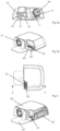
- Fig. 1
- zeigt Pumpmodul und Reservoirmodul einer erfindungsgemässen Verabreichungsvorrichtung in getrenntem Zustand
- Figs. 2a bis 2c
- zeigen den Verbindungsvorgang, bei welchem Pumpmodul und Reservoirmodul über den Bajonettverschluss verbunden werden
- Figs, 3a und 3b
- Zeigen eine erfindungsgemässe Ausführung einer Verabreichungsvorrichtung
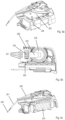
- Fig. 4
- zeigt Schnittansicht durch die Verabreichungsvorrichtung in verbundenen Zustand von Pumpund Reservoirmodul aus
Figs 3a und 3b durch den Bereich der Kontaktanordnungen - Figs. 5a bis 5c
- zeigen Detailansichten des Reservoirmoduls aus
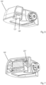
Figur 3b - Fig. 6
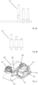
- zeigt alternative Ausführungsform des Pumpmoduls (Kontaktanordnung mit Stiften)
- Fig. 7
- zeigt die alternative Ausführungsform des Pumpmoduls in einer Schnittdarstellung (Kontaktanordnung mit Buchsen)
- Figs. 8a und 8b
- zeigen mögliche erfindungsgemässe Varianten der Stiftausführung für die Kontaktanordnungen
- Fig. 9
- zeigt Reservoirmodul ohne Gehäuse
- Die
Figuren 1 bis 5c sowieFigur 9 zeigen eine erste Ausführungsform der Erfindung. DieFiguren 6 und 7 zeigen eine weitere erfindungsgemässe Ausführungsform. DieFiguren 8a und 8b zeigen vorteilhafte Ausgestaltungen der zweiten Ausführungsform. - Im Folgenden wird nun Bezug auf die erste Ausführungsform genommen, welche in den
Figuren 1 bis 5c undFigur 9 abgebildet ist. Das inFigur 1 dargestellte Verabreichungsgerät 1 ist eine modulare Patch Pumpe (auch Pflasterpumpe genannt), welche von der benutzenden Person direkt auf der Haut getragen werden kann. Das Gerät 1 besteht aus dem Pumpmodul 100 und dem Reservoirmodul 200. Das Pumpmodul 100 ist dabei als wiederverwendbares Modul ausgestaltet. Das Reservoirmodul 200 ist dabei beispielhaft als Einwegmodul ausgestaltet (Mehrwegmodul wäre auch möglich, ohne von der Erfindung abzuweichen). Pumpmodul 100 und Reservoirmodul 200 werden über einen Bajonettverschlusses miteinander verbunden. Hierzu umfasst das Pumpmodul 100 die Verbindungsstruktur 110, welche ihrerseits die Bajonettführungsnuten 111 umfasst, und das Reservoirmodul 200 die Verbindungsstruktur 210, welche die Führungsnocken 211 und die Öffnung 212 umfasst. Die Verbindungsstruktur 110 steht aus dem Gehäuse 140 hervor und kann in die Öffnung 212 eingeführt werden. Zum Schliessen des Bajonettverschlusses werden die beiden Module 100 und 200 zuerst so zu einander ausgerichtet, dass die Führungsnocken 211 (Figur 3b ) in die Führungsnuten 111 eingeschoben werden können (Figur 2a ). Dann werden die beiden Module 100 und 200 zusammen geschoben, bis dass die Führungsnocken 211 die Ecken 111a der Führungsnuten 111 erreichen (Figur 2b ). In einem letzten Schritt werden die beiden Module relativ zueinander rotiert, so dass die Führungsnocken 211 in den Führungsnuten 111 in Richtung der Enden 111b bewegt werden. Zum Schluss der Bewegung verschnappen die beiden Module 100 und 200 über den Schnapperzahn 142 (Figur 3a ) und die Schnappervertiefung 242 (Figur 3b ), wobei die Bodenplatte des Gehäuses 140 des Pumpmoduls 100 parallel oder coplanar zur Bodenplatte 241 des Reservoirmoduls 200 zu liegen kommt (Figur 2c ). Die Rotation der Module 100 und 200 relativ zueinander kann vorteilhaft von einer leichten axialen Bewegung überlagert werden, wobei die beiden Module 100 und 200 zueinander hin gezogen werden, um einen festen, spielarmen und toleranzarmen Sitz des Reservoirmoduls 200 am Pumpmodul 100 zu erzielen. Vorteilhaft an dieser Bajonettverbindung ist sodann, dass wie schon erwähnt, Toleranzen aufgehoben werden können und durch den festen Sitz des Reservoirmoduls 200 am Pumpmodul 100 ist auch eine Übertragung von Kräften, insbesondere von Kräften, welche durch den Antrieb generiert werden, zwischen den Modulen unproblematisch. - Die Verabreichungsvorrichtung 1 umfasst einen konventionellen Ausschüttmechanismus. Zum Ausschütten von Medikament kann eine im Pumpmodul angeordnete Kolbenstange 180 ins Reservoir 280 des Reservoirmoduls 200 hineingefahren werden. Der Kolben 281 des Reservoirs 280 kann dabei verschoben und damit das Volumen im Reservoir 280 verkleinert werden, wodurch Medikament aus dem Reservoir 280 verdrängt wird und durch den Infusionspfad 290 und die Infusionskanüle 291 heraus verabreicht wird (siehe
Figuren 2a ,5c und9 ). Die Infusionskanüle 291 kann vorgängig mittels einer Insertionskanüle 292 und einen mit dem Infusionspfad verbunden Insertionsmechanismus 260 in das Gewebe der benutzenden Person eingebracht worden sein. - Pumpmodul 100 und Reservoirmodul 200 werden beim Schliessen der Bajonettverbindung nicht nur mechanisch sondern auch elektrisch miteinander verbunden. Die geschieht über die Kontaktanordnung 120 des Pumpmoduls und die komplementär dazu ausgebildete Kontaktanordnung 220 des Reservoirmoduls 200. Erfindungsgemäss sind die Kontaktanordnungen 120 und 220 von den Verbindungsstrukturen geometrisch abgesetzt, so dass während der beschriebenen Rotation beim Schliessen der Bajonettverbindung der relative Weg, welchen die Kontaktanordnungen 120 und 220 zurücklegen, grösser ist, als derjenige, den zum Bespiel die Führungsnocken 211 zurücklegen. Die Kontaktanordnung 120 des Pumpmoduls umfasst mehrere elektrische Kontakte 121, welche streifenförmig auf einem Stecker 122 angeordnet sind (
Figur 3a ). Komplementär dazu umfasst die Kontaktanordnung 220 des Reservoirmoduls 200 eine Buchse 222 in welcher die Kontaktzungen 221 angeordnet sind (Figuren 3b und 4 ). Am Rand der Buchse 222 ist eine Dichtlippe 223 angeordnet, welche bei geschlossener Bajonettverbindung dazu dient zu verhindern, dass Flüssigkeit durch die Kontaktanordnung hindurch in das Reservoirmodul 200 eindringen kann. Die Kontaktzungen 221 sind vorzugsweise federnd ausgestaltet, zum Beispiel hergestellt aus einem metallischen Stanzbiegeteil. Beim Schliessen der Bajonettverbindung wird der Stecker 122 in die Buchse 222 eingeschoben und die Kontaktzungen 221 kontaktieren die streifenförmigen Kontakte 121 auf dem Stecker 122. Die Streifenform der Kontakte 121 ermöglicht vorteilhaft die Kontaktierung durch die Kontaktzungen 221 entlang einer gewissen Strecke. Die federnde Ausgestaltung der Kontaktzungen 221 hat weiter den Vorteil, dass sie die oben erwähnte der Rotation überlagerte axiale Bewegung aufnehmen und bei der Kontaktierung ausgleichen kann. - Das Reservoirmodul umfasst vorteilhaft, wie in den
Figuren 4 ,5a-c und9 gezeigt, nebst den bereits erwähnten Elementen weitere Elemente. - So umfasst das Reservoirmodul 200 in einer Ausgestaltung mindestens eine Energiequelle, zum Beispiel in Form der Primärzelle oder Batterie 230. Die Batterie 230 kann dazu dienen, eine im Pumpmodul angeordnete Sekundärzelle (z. B. eine wiederaufladbare Zelle) und/oder den Antrieb der Verabreichungseinrichtung mit elektrischer Energie zu versorgen. Weiter kann die Batterie dazu verwendet werden, elektrische und/oder elektronische Elemente, welche im Reservoirmodul 200 angeordnet sind, mit Energie zu versorgen. Die
Figuren 5a bis 5c zeigen beispielhaft wie die Batterie 230 im Reservoirmodul angeordnet sein kann. In der gezeigten Ausführung wird die Batterie 230 durch den zungenförmigen Batteriekontakt 225 im Reservoirmodul 200 gehalten. Der Batteriekontakt 225 ist dabei in einer vorteilhaften Ausgestaltung wie die Kontaktzungen 221 federnd ausgestaltet, zum Beispiel hergestellt aus einem metallischen Stanzbiegeteil. Der Batteriekontakt 225 kontaktiert den einen Pol der Batterie 230 und ein weiterer (nicht gezeigter) Kontakt stellt die elektrische Verbindung mit dem anderen Pol der Batterie 230 her. - Weiter umfasst das Reserviormodul 200 in einer Ausgestaltung mindestens ein Elektronikboard 250 (
Figuren 5a bis 5c ). Das Elektronikboard 250 kann einen elektronischen Speicher zum Speichern von Information umfassen. Darin können (nicht abschliessend) Informationen wie Herstelldatum des Reservoirmoduls 200, Seriennummer, Informationen aus potentiell im Reservoirmodul vorhandene Sensoren, insbesondere ein Temperaturlogfile, oder Betriebsparameter gespeichert sein. Weiter kann das Elektronikboard 250 eine Steuerung für den weiter oben erwähnten Insertionsmechanismus 260 (Figur 9 ) umfassen. In einer vorteilhaften Ausgestaltung wird dabei von der Steuerung eine Auslöseanordnung 270 für den Insertionsmechanismus 260 gesteuert. Das Elektronikboard kann beispielhaft über die Kontakte 224 (insbesondereFiguren 5b und 5c ) mit der Batterie 230 oder der Kontaktanordnung 220 verbunden sein. In einer vorteilhaften Ausführung werden die Kontaktzungen 221, die Kontakte 224 sowie der Batteriekontakt 225 aus einem Stanzbiege- /Kunststoffhybridbauteil hergestellt, insbesondere aus einem Bauteil bestehend aus einem metallischen Stanzbiegeteil umspritzt mit einem elektrisch isolierend wirkenden Kunststoff. Unter anderem vorteilhaft an dieser Ausführung ist, dass das Stanzbiege-Kunststoff-Hybridbauteil sodann in einem Montageschritt zusammen mit der Batterie 230 am Reservoirmodul montiert, insbesondere verschnappt (siehe Element 226 inFiguren 5a und 5b ) werden kann. - Weiter umfasst das Reservoirmodul 200 in einer Ausgestaltung die schon erwähnte Auslöseanordnung 270 für den Insertionsmechanismus 260, wobei für mögliche Ausführungen der Anordnung 270 und des Mechanismus 260 an dieser Stelle noch einmal auf die europäischen Patentanmeldungen
18199475.7 17209749.5 17209764.4 17209772.7 - Die
Figuren 6 und 7 zeigen eine zweite erfindungsgemässe Ausführungsform. DieFiguren 8a und 8b zwei mögliche Ausgestaltungsdetails der zweiten Ausführungsform. Im Folgenden wird auf die Unterschiede zur ersten Ausführungsform eingegangen. Die anderen Aspekte stimmen mit der ersten Ausführungsform weitestgehend überein und werden per Verweis auch in diese Ausführungsform übernommen. Der Hauptunterschied zur ersten Ausführungsform liegt in den Kontaktanordnungen von Pumpmodul 100' und dem angepassten Reservoirmodul (nicht gezeigt). Die Kontaktanordnung 120' umfasst nicht einen einzelnen Stecker, auf welchem Kontakte angeordnet sind, sondern einzelne Kontaktstifte 121'. Das Reservoirmodul (nicht gezeigt) kann komplementär dazu einzelne Buchsen für jeden Kontaktstift umfassen. Hierbei sind die einzelnen Buchsen in einer vorteilhaften Ausgestaltung schwimmend im Reservoirmodul (nicht gezeigt) gelagert, so dass eine allfällige axiale Bewegung während der erwähnten Rotationsbewegung beim Schliessen des Bajonetts ausgeglichen werden kann. In einer alternativen Ausgestaltung kann das Reservoirmodul für die zweite Ausführungsform auch ähnlich oder sogar gleich wie in der ersten Ausführungsform ausgestaltet, so dass nur eine Buchse alle Kontaktstifte aufnimmt. Hierbei können die Kontaktzungen in der Kontaktanordnung des Reservoirmoduls (nicht gezeigt) geometrisch so geformt werden, dass sie gut zu den Stiften passen. - Die
Figuren 8a und 8b zeigen zwei alternative Ausgestaltungen der Kontaktstifte. InFigur 8a weisen die Stifte 121' jeweils eine feste Länge auf.Figur 8b zeigt eine Alternative, bei welcher die Stifte als federnde und teleskopierbare Stifte 121 "mit variabler Länge ausgestaltet sind, zum Beispiel als sogenannte Pogo-Stifte. Kommt diese alternative Ausgestaltung der Kontaktstifte 121" zum Einsatz, kann im Gegenzug die Kontaktanordnung im Reservoirmodul (nicht gezeigt) vereinfacht werden. Die Kontaktanordnung des Reservoirmoduls (nicht gezeigt) kann sodann einfacher und unbeweglich am Reservoirmodul (nicht gezeigt) angeordnete Kontaktflächen aufweisen. -
- 1
- Verabreichungsvorrichtung
- 100
- Pumpmodul
- 100'
- Pumpmodul
- 110
- Verbindungstruktur Pumpmodul
- 111
- Führungsnuten Bajonett
- 111a
- Ecke
- 111b
- Ende Führungsnut
- 120
- Kontaktanordnung Pumpmodul
- 120'
- Kontaktanordnung Pumpmodul
- 121
- elektrische Kontakte
- 121'
- elektrische Kontaktstifte
- 121"
- teleskopierbare elektrische Kontaktstifte
- 122
- Stecker
- 140
- Gehäuse Pumpmodul
- 142
- Schnapperzahn
- 180
- Kolbenstange Pumpmodul
- 200
- Reservoirmodul
- 210
- Verbindungstruktur Reservoirmodul
- 211
- Führungsnocken Bajonett
- 212
- Öffnung
- 220
- Kontaktanordnung Reservoirmodul
- 221
- elektrische Kontaktzungen
- 222
- Buchse
- 223
- Dichtlippe
- 224
- Kontaktierung Elektronikboard
- 225
- Batteriekontakt
- 226
- Verschnappung
- 230
- Primärzelle oder Batterie
- 240
- Gehäuse Reservoirmodul
- 241
- Bodenplatte Reservoirmodul
- 242
- Schnappervertiefung
- 250
- Elektronikboard Reservoirmodul
- 260
- Insertionsmechanismus für Infusionskanüle
- 270
- Auslöseanordnung für Insertionsmechanismus
- 280
- Reservoir
- 281
- Reservoirkolben
- 290
- Infusionspfad
- 291
- Infusionskanüle
- 292
- Insertionskanüle/-nadel
Claims (9)
- Modulare Vorrichtung (1) zur Verabreichung einer fluiden Medikamentenformulierung, welche auf der Haut einer benutzenden Person fixierbar ist, umfassendein Reservoirmodul (200) mit einem Reservoir (280) für die Medikamentenformulierung, wobei das Reservoir (280) eine erste Achse definiert, und wobei das Reservoirmodul (200) eine erste Verbindungstruktur (210) sowie eine erste elektrische Kontaktanordnung (220) umfasst, undein Pumpmodul (100) mit einer Kolbenstange (180), welche eine zweite Achse definiert, wobei das Pumpmodul (100) eine zweite Verbindungsstruktur (110) umfasst, welche um die Kolbenstange (180) herum angeordnet ist, und wobei das Pumpmodul (100) weiter eine zweite elektrische Kontaktanordnung (120) umfasst,wobei das Reservoirmodul (200) und das Pumpmodul (100) lösbar über die erste und die zweite Verbindungstruktur (110) miteinander verbindbar sind, so dass durch Bewegung der Kolbenstange (180) Medikamentenformulierung aus dem Reservoir (280) verdrängbar ist,wobei zum Verbinden der Module (100, 200)in einem ersten Schritt die erste und die zweite Verbindungsstruktur (210, 110) zusammengesteckt werden, so dass die erste und zweite Achse auf eine gemeinsame Achse zu liegen kommen, und so eine Rotationsachse bilden,in einem zweiten Schritt das Pumpmodul (100) relativ zum Reservoirmodul (200) um die Rotationsachse rotiert wird, und beim zweiten Schritt durch die Rotation die erste Kontaktanordnung (220) mit der zweiten Kontaktanordnung (120) elektrisch leitend verbunden wird,wobei die erste Kontaktanordnung (220) in radialer Richtung von der ersten Achse weiter entfernt ist als die erste Verbindungsstruktur (210), unddie zweite Kontaktanordnung (120) in radialer Richtung von der zweiten Achse weiter entfernt ist als die zweite Verbindungsstruktur (110).
- Modulare Vorrichtung nach Anspruch 1, dadurch gekennzeichnet, dass die erste und die zweite Verbindungsstruktur (210, 110) zusammen einen Bajonettverschluss bilden.
- Modulare Vorrichtung nach Anspruch 1 oder 2, wobei die erste Kontaktanordnung (220) mindestens eine Buchse (222) umfasst und die zweite Kontaktanordnung (120) komplementär mindestens einen in die Buchse (222) passenden Stift (121) oder Stecker (122) umfasst.
- Modulare Vorrichtung nach Anspruch 1 oder 2, wobei die erste Kontaktanordnung (220) mehrere parallel zueinander angeordnete Buchsen (222) umfasst und die zweite Kontaktanordnung (120) passend eine entsprechende Anzahl Stifte (121) oder Stecker (122) umfasst, welche geometrisch in die Buchsen (222) passen.
- Modulare Vorrichtung nach Anspruch 3 oder 4, wobei die Buchsen (222) der ersten Kontaktanordnung (220), sowie die Stifte (121) oder Stecker (122) der zweiten Kontakanordnung in etwa senkrecht zur ersten respektive zweiten Achse stehen.
- Modulare Vorrichtung nach einem der vorhergehenden Ansprüche, wobei die erste Kontaktanordnung (220) beweglich, insbesondere schwimmend, im Reservoirmodul (200) gelagert ist.
- Modulare Vorrichtung nach Anspruch 6, wobei die zweite Kontaktanordnung (120) starr am Pumpenmodul (100) angeordnet ist.
- Modulare Vorrichtung nach einem der vorhergehenden Ansprüche, wobei das Reservoirmodul (200) weiter einen Fluidpfad (290) mit einer Infusionskanüle (291) und einen Insertionsmechanismus (260) zum Einbringen der Infusionskanüle (291) in das Gewebe der benutzenden Person umfasst.
- Modulare Vorrichtung nach einem der vorhergehenden Ansprüche, wobei das Reservoirmodul (200) weiter einen Speicher für elektrische Energie, insbesondere eine Primärzelle oder Batterie (230), und einen zungenförmigen Batteriekontakt (225) umfasst, wobei der Batteriekontakt (225) ein freies federndes Ende und ein am Reservoirmodul fest angeordnetes Ende umfasst, und wobei die das freie Ende den Speicher für elektrische Energie (230) in ein vorgesehenes Volumen im Reservoir-modul (200) hineindrückt und hält.
Applications Claiming Priority (2)
| Application Number | Priority Date | Filing Date | Title |
|---|---|---|---|
| CH00055/19A CH715757A2 (de) | 2019-01-17 | 2019-01-17 | Modulares Verabreichungsgerät für fluide Medikamentenformulierung. |
| PCT/IB2019/059913 WO2020148581A1 (de) | 2019-01-17 | 2019-11-19 | Verbessertes modulares verabreichungsgerät |
Publications (3)
| Publication Number | Publication Date |
|---|---|
| EP3911378A1 EP3911378A1 (de) | 2021-11-24 |
| EP3911378C0 EP3911378C0 (de) | 2024-09-25 |
| EP3911378B1 true EP3911378B1 (de) | 2024-09-25 |
Family
ID=68696478
Family Applications (1)
| Application Number | Title | Priority Date | Filing Date |
|---|---|---|---|
| EP19809626.5A Active EP3911378B1 (de) | 2019-01-17 | 2019-11-19 | Verbessertes modulares verabreichungsgerät |
Country Status (5)
| Country | Link |
|---|---|
| US (1) | US12403241B2 (de) |
| EP (1) | EP3911378B1 (de) |
| CN (1) | CN113329776B (de) |
| CH (1) | CH715757A2 (de) |
| WO (1) | WO2020148581A1 (de) |
Families Citing this family (19)
| Publication number | Priority date | Publication date | Assignee | Title |
|---|---|---|---|---|
| PT1762259E (pt) | 2005-09-12 | 2010-12-10 | Unomedical As | Insersor para um conjunto de infusão com uma primeira e uma segunda unidades de mola |
| US10194938B2 (en) | 2011-03-14 | 2019-02-05 | UnoMedical, AS | Inserter system with transport protection |
| CH715757A2 (de) | 2019-01-17 | 2020-07-31 | Tecpharma Licensing Ag | Modulares Verabreichungsgerät für fluide Medikamentenformulierung. |
| CA3141608A1 (en) | 2019-05-20 | 2020-11-26 | Unomedical A/S | Rotatable infusion device and methods thereof |
| USD950713S1 (en) * | 2019-10-31 | 2022-05-03 | Eoflow Co., Ltd. | Medicine injector |
| US12508362B2 (en) * | 2020-09-08 | 2025-12-30 | Medtrum Technologies Inc. | Infusion needle structure of drug infusion device |
| EP4237042A4 (de) * | 2020-10-30 | 2024-10-09 | Medtrum Technologies Inc. | Pflasterartige arzneimittelinfusionsvorrichtung |
| EP4274641A4 (de) * | 2021-01-05 | 2024-11-20 | Medtrum Technologies Inc. | Infusionsvorrichtung für hautpflaster |
| US20240115799A1 (en) * | 2021-01-05 | 2024-04-11 | Medtrum Technologies Inc. | Skin patch drug infusion device |
| JP2024515352A (ja) | 2021-04-23 | 2024-04-09 | ウノメディカル アクティーゼルスカブ | 小型パッチポンプシステム |
| EP4169547B1 (de) * | 2021-10-25 | 2024-10-02 | TecMed AG | Verbesserte verabreichungsvorrichtung |
| USD1071155S1 (en) * | 2022-10-17 | 2025-04-15 | Becton, Dickinson And Company | On-body fillable injector |
| USD1030042S1 (en) * | 2022-12-30 | 2024-06-04 | Becton, Dickinson And Company | On-body fillable injector |
| USD1071151S1 (en) | 2022-12-30 | 2025-04-15 | Becton, Dickinson And Company | On-body fillable injector |
| USD1033633S1 (en) * | 2022-12-30 | 2024-07-02 | Becton, Dickinson And Company | On-body fillable injector |
| USD1071158S1 (en) | 2022-12-30 | 2025-04-15 | Becton, Dickinson And Company | On-body fillable injector |
| USD1030043S1 (en) * | 2022-12-30 | 2024-06-04 | Becton, Dickinson And Company | On-body fillable injector |
| USD1071157S1 (en) * | 2022-12-30 | 2025-04-15 | Becton, Dickinson And Company | On-body fillable injector |
| USD1046120S1 (en) | 2022-12-30 | 2024-10-08 | Becton, Dickinson And Company | On-body fillable injector |
Family Cites Families (27)
| Publication number | Priority date | Publication date | Assignee | Title |
|---|---|---|---|---|
| US5941846A (en) * | 1995-03-13 | 1999-08-24 | Alaris Medical Systems, Inc. | Method and apparatus for power connection in a modular patient care system |
| DE69928827T2 (de) * | 1998-10-29 | 2006-08-31 | Medtronic MiniMed, Inc., Northridge | Reservoiranschluss |
| US7128727B2 (en) | 2002-09-30 | 2006-10-31 | Flaherty J Christopher | Components and methods for patient infusion device |
| WO2009013733A2 (en) * | 2007-07-20 | 2009-01-29 | Medingo Ltd. | Collapsible reservoir for use with a delivery device |
| EP3639869A1 (de) | 2008-04-09 | 2020-04-22 | Roche Diabetes Care GmbH | Systeme, vorrichtungen und verfahren zur flüssigkeitsabgabe |
| CA2930329A1 (en) | 2008-08-18 | 2010-02-25 | Calibra Medical, Inc. | Drug infusion system with reusable and disposable components |
| US9125981B2 (en) * | 2009-02-21 | 2015-09-08 | Incumed, Llc | Fluid cartridges including a power source and partially implantable medical devices for use with same |
| CN102918617B (zh) * | 2010-06-03 | 2015-05-13 | 三菱电机株式会社 | 开关装置 |
| US9308320B2 (en) * | 2010-09-24 | 2016-04-12 | Perqflo, Llc | Infusion pumps |
| EP3682871A1 (de) * | 2012-03-05 | 2020-07-22 | Becton, Dickinson and Company | Vorrichtung zum ablösen von kleber |
| GB2525149A (en) * | 2014-01-30 | 2015-10-21 | Cellnovo Ltd | Therapeutic product delivery device |
| GB2525150A (en) * | 2014-01-30 | 2015-10-21 | Cellnovo Ltd | Therapeutic product delivery device |
| CN106029125B (zh) * | 2014-02-26 | 2019-11-19 | 特克法马许可公司 | 用于给送流体产品的装置 |
| US9814815B2 (en) * | 2014-12-17 | 2017-11-14 | Heartware, Inc. | Implantable connector |
| US9993595B2 (en) * | 2015-05-18 | 2018-06-12 | Tandem Diabetes Care, Inc. | Patch pump cartridge attachment |
| EP3184028A4 (de) * | 2015-06-03 | 2018-05-16 | Olympus Corporation | Anschlussstück für endoskop |
| GB201600232D0 (en) * | 2016-01-06 | 2016-02-17 | Vicentra B V | Fluid delivery system |
| CN206682151U (zh) * | 2017-05-02 | 2017-11-28 | 潍坊歌尔电子有限公司 | 一种转轴结构 |
| CN119868710A (zh) * | 2017-06-15 | 2025-04-25 | 以色列三级跳远有限责任公司 | 用于管理糖尿病的贴片泵系统和装置及其方法 |
| EP3443996A1 (de) * | 2017-08-18 | 2019-02-20 | TecPharma Licensing AG | Patch-pumpe |
| CN107288437A (zh) * | 2017-08-27 | 2017-10-24 | 黎志瀛 | 一种电控门锁供电装置 |
| EP3501577A1 (de) | 2017-12-21 | 2019-06-26 | TecPharma Licensing AG | Kanüleninsertionsmechanismus |
| EP3501573A1 (de) | 2017-12-21 | 2019-06-26 | TecPharma Licensing AG | Kanüleninsertionsmechanismus |
| EP3501569A1 (de) | 2017-12-21 | 2019-06-26 | TecPharma Licensing AG | Kanüleninsertionsmechanismus |
| CN108539550B (zh) * | 2018-02-13 | 2023-05-05 | 酷闪电器(上海)有限公司 | 一种电力分配用分接器及电源分配装置 |
| EP3636298A1 (de) | 2018-10-10 | 2020-04-15 | Tecpharma Licensing AG | Einstechvorrichtung für eine verabreichungsvorrichtung |
| CH715757A2 (de) | 2019-01-17 | 2020-07-31 | Tecpharma Licensing Ag | Modulares Verabreichungsgerät für fluide Medikamentenformulierung. |
-
2019
- 2019-01-17 CH CH00055/19A patent/CH715757A2/de not_active Application Discontinuation
- 2019-11-19 EP EP19809626.5A patent/EP3911378B1/de active Active
- 2019-11-19 WO PCT/IB2019/059913 patent/WO2020148581A1/de not_active Ceased
- 2019-11-19 CN CN201980089409.6A patent/CN113329776B/zh active Active
-
2021
- 2021-07-13 US US17/374,213 patent/US12403241B2/en active Active
Also Published As
| Publication number | Publication date |
|---|---|
| WO2020148581A1 (de) | 2020-07-23 |
| CN113329776B (zh) | 2023-09-15 |
| CN113329776A (zh) | 2021-08-31 |
| CH715757A2 (de) | 2020-07-31 |
| EP3911378A1 (de) | 2021-11-24 |
| EP3911378C0 (de) | 2024-09-25 |
| US20210338924A1 (en) | 2021-11-04 |
| US12403241B2 (en) | 2025-09-02 |
Similar Documents
| Publication | Publication Date | Title |
|---|---|---|
| CH715757A2 (de) | Modulares Verabreichungsgerät für fluide Medikamentenformulierung. | |
| EP4169547B1 (de) | Verbesserte verabreichungsvorrichtung | |
| DE69927196T2 (de) | Stiftförmige Medikamentenspritze | |
| EP1414505B1 (de) | Verabreichungsgerät mit dosiervorrichtung | |
| DE10163325B4 (de) | Verriegelungssperre für eine Verbindung von Gehäuseabschnitten eines Verabreichungsgeräts | |
| WO2020074988A1 (de) | Einstechvorrichtung für eine verabreichungsvorrichtung | |
| EP1045146A2 (de) | Medizinische Dosierpumpe | |
| WO2017219158A1 (de) | Karpulenaufnahmevorrichtung und verfahren zur montage einer karpule darin | |
| WO2003011374A1 (de) | Verabreichungsgerät mit verdrehsicherung | |
| EP2531164A1 (de) | Vorrichtung zum entnehmen eines fluids aus einem vial | |
| DE60022570T2 (de) | Schnellsperrverbindungskopf für implantierbare medizinische Vorrichtung | |
| DE202010018328U1 (de) | Stopfen für eine Kartusche für Medikamentenabgabevorrichtungen | |
| DE69918545T2 (de) | Infusionssystem mit patientenseitig kontrollierter dosiervorrichtung | |
| EP3938014A1 (de) | Dosiereinrichtung für eine injektionsvorrichtung | |
| EP2023976A1 (de) | Vorrichtung zur verabreichung eines fluiden produkts | |
| EP2123326A1 (de) | Implantierbare Schockelektrodenleitung und implantierbare Defibrillationsanordnung | |
| DE10032937A1 (de) | Medikamentenausgabevorrichtung | |
| EP3773807B1 (de) | Dosiervorrichtung mit stelleinrichtung für einen injektor | |
| WO2020053682A1 (de) | Rückdrehsicherungsanordnung für injektionsgerät | |
| DE60021869T2 (de) | Kassette zur aufbewahrung und zufuhr fester arzneimittel | |
| WO2017011926A1 (de) | Injektionsvorrichtung mit kupplungen | |
| CH711379A2 (de) | Injektionsvorrichtung. | |
| CH719185A2 (de) | Injektionsvorrichtung mit mindestens zwei Schalenteilen und Verfahren zum Montieren einer solchen Injektionsvorrichtung. | |
| DE202024104776U1 (de) | Medizinprodukt | |
| EP4623962A1 (de) | Injektionsvorrichtung zur verabreichung eines fluiden produkts und verfahren zum zusammenbauen dieser vorrichtung |
Legal Events
| Date | Code | Title | Description |
|---|---|---|---|
| STAA | Information on the status of an ep patent application or granted ep patent |
Free format text: STATUS: UNKNOWN |
|
| STAA | Information on the status of an ep patent application or granted ep patent |
Free format text: STATUS: THE INTERNATIONAL PUBLICATION HAS BEEN MADE |
|
| PUAI | Public reference made under article 153(3) epc to a published international application that has entered the european phase |
Free format text: ORIGINAL CODE: 0009012 |
|
| STAA | Information on the status of an ep patent application or granted ep patent |
Free format text: STATUS: REQUEST FOR EXAMINATION WAS MADE |
|
| 17P | Request for examination filed |
Effective date: 20210817 |
|
| AK | Designated contracting states |
Kind code of ref document: A1 Designated state(s): AL AT BE BG CH CY CZ DE DK EE ES FI FR GB GR HR HU IE IS IT LI LT LU LV MC MK MT NL NO PL PT RO RS SE SI SK SM TR |
|
| DAV | Request for validation of the european patent (deleted) | ||
| DAX | Request for extension of the european patent (deleted) | ||
| GRAP | Despatch of communication of intention to grant a patent |
Free format text: ORIGINAL CODE: EPIDOSNIGR1 |
|
| STAA | Information on the status of an ep patent application or granted ep patent |
Free format text: STATUS: GRANT OF PATENT IS INTENDED |
|
| INTG | Intention to grant announced |
Effective date: 20240422 |
|
| GRAS | Grant fee paid |
Free format text: ORIGINAL CODE: EPIDOSNIGR3 |
|
| GRAA | (expected) grant |
Free format text: ORIGINAL CODE: 0009210 |
|
| STAA | Information on the status of an ep patent application or granted ep patent |
Free format text: STATUS: THE PATENT HAS BEEN GRANTED |
|
| AK | Designated contracting states |
Kind code of ref document: B1 Designated state(s): AL AT BE BG CH CY CZ DE DK EE ES FI FR GB GR HR HU IE IS IT LI LT LU LV MC MK MT NL NO PL PT RO RS SE SI SK SM TR |
|
| REG | Reference to a national code |
Ref country code: GB Ref legal event code: FG4D Free format text: NOT ENGLISH |
|
| REG | Reference to a national code |
Ref country code: CH Ref legal event code: EP |
|
| REG | Reference to a national code |
Ref country code: DE Ref legal event code: R096 Ref document number: 502019012205 Country of ref document: DE |
|
| REG | Reference to a national code |
Ref country code: IE Ref legal event code: FG4D Free format text: LANGUAGE OF EP DOCUMENT: GERMAN |
|
| U01 | Request for unitary effect filed |
Effective date: 20241021 |
|
| U07 | Unitary effect registered |
Designated state(s): AT BE BG DE DK EE FI FR IT LT LU LV MT NL PT RO SE SI Effective date: 20241104 |
|
| PG25 | Lapsed in a contracting state [announced via postgrant information from national office to epo] |
Ref country code: NO Free format text: LAPSE BECAUSE OF FAILURE TO SUBMIT A TRANSLATION OF THE DESCRIPTION OR TO PAY THE FEE WITHIN THE PRESCRIBED TIME-LIMIT Effective date: 20241225 |
|
| PG25 | Lapsed in a contracting state [announced via postgrant information from national office to epo] |
Ref country code: GR Free format text: LAPSE BECAUSE OF FAILURE TO SUBMIT A TRANSLATION OF THE DESCRIPTION OR TO PAY THE FEE WITHIN THE PRESCRIBED TIME-LIMIT Effective date: 20241226 |
|
| PG25 | Lapsed in a contracting state [announced via postgrant information from national office to epo] |
Ref country code: RS Free format text: LAPSE BECAUSE OF FAILURE TO SUBMIT A TRANSLATION OF THE DESCRIPTION OR TO PAY THE FEE WITHIN THE PRESCRIBED TIME-LIMIT Effective date: 20241225 |
|
| PG25 | Lapsed in a contracting state [announced via postgrant information from national office to epo] |
Ref country code: RS Free format text: LAPSE BECAUSE OF FAILURE TO SUBMIT A TRANSLATION OF THE DESCRIPTION OR TO PAY THE FEE WITHIN THE PRESCRIBED TIME-LIMIT Effective date: 20241225 Ref country code: NO Free format text: LAPSE BECAUSE OF FAILURE TO SUBMIT A TRANSLATION OF THE DESCRIPTION OR TO PAY THE FEE WITHIN THE PRESCRIBED TIME-LIMIT Effective date: 20241225 Ref country code: GR Free format text: LAPSE BECAUSE OF FAILURE TO SUBMIT A TRANSLATION OF THE DESCRIPTION OR TO PAY THE FEE WITHIN THE PRESCRIBED TIME-LIMIT Effective date: 20241226 |
|
| U20 | Renewal fee for the european patent with unitary effect paid |
Year of fee payment: 6 Effective date: 20250204 |
|
| PG25 | Lapsed in a contracting state [announced via postgrant information from national office to epo] |
Ref country code: IS Free format text: LAPSE BECAUSE OF FAILURE TO SUBMIT A TRANSLATION OF THE DESCRIPTION OR TO PAY THE FEE WITHIN THE PRESCRIBED TIME-LIMIT Effective date: 20250125 |
|
| PG25 | Lapsed in a contracting state [announced via postgrant information from national office to epo] |
Ref country code: SM Free format text: LAPSE BECAUSE OF FAILURE TO SUBMIT A TRANSLATION OF THE DESCRIPTION OR TO PAY THE FEE WITHIN THE PRESCRIBED TIME-LIMIT Effective date: 20240925 |
|
| PG25 | Lapsed in a contracting state [announced via postgrant information from national office to epo] |
Ref country code: ES Free format text: LAPSE BECAUSE OF FAILURE TO SUBMIT A TRANSLATION OF THE DESCRIPTION OR TO PAY THE FEE WITHIN THE PRESCRIBED TIME-LIMIT Effective date: 20240925 |
|
| PG25 | Lapsed in a contracting state [announced via postgrant information from national office to epo] |
Ref country code: PL Free format text: LAPSE BECAUSE OF FAILURE TO SUBMIT A TRANSLATION OF THE DESCRIPTION OR TO PAY THE FEE WITHIN THE PRESCRIBED TIME-LIMIT Effective date: 20240925 Ref country code: CZ Free format text: LAPSE BECAUSE OF FAILURE TO SUBMIT A TRANSLATION OF THE DESCRIPTION OR TO PAY THE FEE WITHIN THE PRESCRIBED TIME-LIMIT Effective date: 20240925 |
|
| PG25 | Lapsed in a contracting state [announced via postgrant information from national office to epo] |
Ref country code: SK Free format text: LAPSE BECAUSE OF FAILURE TO SUBMIT A TRANSLATION OF THE DESCRIPTION OR TO PAY THE FEE WITHIN THE PRESCRIBED TIME-LIMIT Effective date: 20240925 |
|
| PG25 | Lapsed in a contracting state [announced via postgrant information from national office to epo] |
Ref country code: MC Free format text: LAPSE BECAUSE OF FAILURE TO SUBMIT A TRANSLATION OF THE DESCRIPTION OR TO PAY THE FEE WITHIN THE PRESCRIBED TIME-LIMIT Effective date: 20240925 |
|
| PLBE | No opposition filed within time limit |
Free format text: ORIGINAL CODE: 0009261 |
|
| STAA | Information on the status of an ep patent application or granted ep patent |
Free format text: STATUS: NO OPPOSITION FILED WITHIN TIME LIMIT |
|
| 26N | No opposition filed |
Effective date: 20250626 |
|
| PG25 | Lapsed in a contracting state [announced via postgrant information from national office to epo] |
Ref country code: IE Free format text: LAPSE BECAUSE OF NON-PAYMENT OF DUE FEES Effective date: 20241119 |
|
| REG | Reference to a national code |
Ref country code: CH Ref legal event code: U11 Free format text: ST27 STATUS EVENT CODE: U-0-0-U10-U11 (AS PROVIDED BY THE NATIONAL OFFICE) Effective date: 20251201 |
|
| U1N | Appointed representative for the unitary patent procedure changed after the registration of the unitary effect |
Representative=s name: FINKLENBURG, SUSANNE; CH |
|
| U20 | Renewal fee for the european patent with unitary effect paid |
Year of fee payment: 7 Effective date: 20251201 |
|
| PGFP | Annual fee paid to national office [announced via postgrant information from national office to epo] |
Ref country code: GB Payment date: 20251120 Year of fee payment: 7 |
|
| PG25 | Lapsed in a contracting state [announced via postgrant information from national office to epo] |
Ref country code: HR Free format text: LAPSE BECAUSE OF FAILURE TO SUBMIT A TRANSLATION OF THE DESCRIPTION OR TO PAY THE FEE WITHIN THE PRESCRIBED TIME-LIMIT Effective date: 20240925 |
|
| PGFP | Annual fee paid to national office [announced via postgrant information from national office to epo] |
Ref country code: CH Payment date: 20251201 Year of fee payment: 7 |
|
| PG25 | Lapsed in a contracting state [announced via postgrant information from national office to epo] |
Ref country code: HU Free format text: LAPSE BECAUSE OF FAILURE TO SUBMIT A TRANSLATION OF THE DESCRIPTION OR TO PAY THE FEE WITHIN THE PRESCRIBED TIME-LIMIT; INVALID AB INITIO Effective date: 20191119 |
|
| REG | Reference to a national code |
Ref country code: CH Ref legal event code: R14 Free format text: ST27 STATUS EVENT CODE: U-0-0-R10-R14 (AS PROVIDED BY THE NATIONAL OFFICE) Effective date: 20260310 |
|
| PG25 | Lapsed in a contracting state [announced via postgrant information from national office to epo] |
Ref country code: CY Free format text: LAPSE BECAUSE OF FAILURE TO SUBMIT A TRANSLATION OF THE DESCRIPTION OR TO PAY THE FEE WITHIN THE PRESCRIBED TIME-LIMIT; INVALID AB INITIO Effective date: 20191119 |
|
| U1K | Transfer of rights of the unitary patent after the registration of the unitary effect |
Owner name: MYLIFE DIABETES CARE AG; CH |