EP3910258B1 - Klimatisierungsvorrichtung - Google Patents
Klimatisierungsvorrichtung Download PDFInfo
- Publication number
- EP3910258B1 EP3910258B1 EP19908805.5A EP19908805A EP3910258B1 EP 3910258 B1 EP3910258 B1 EP 3910258B1 EP 19908805 A EP19908805 A EP 19908805A EP 3910258 B1 EP3910258 B1 EP 3910258B1
- Authority
- EP
- European Patent Office
- Prior art keywords
- air
- refrigerant
- space
- conditioning apparatus
- fan
- Prior art date
- Legal status (The legal status is an assumption and is not a legal conclusion. Google has not performed a legal analysis and makes no representation as to the accuracy of the status listed.)
- Active
Links
Images

Classifications
-
- F—MECHANICAL ENGINEERING; LIGHTING; HEATING; WEAPONS; BLASTING
- F24—HEATING; RANGES; VENTILATING
- F24F—AIR-CONDITIONING; AIR-HUMIDIFICATION; VENTILATION; USE OF AIR CURRENTS FOR SCREENING
- F24F1/00—Room units for air-conditioning, e.g. separate or self-contained units or units receiving primary air from a central station
- F24F1/0007—Indoor units, e.g. fan coil units
- F24F1/0043—Indoor units, e.g. fan coil units characterised by mounting arrangements
- F24F1/0047—Indoor units, e.g. fan coil units characterised by mounting arrangements mounted in the ceiling or at the ceiling
-
- F—MECHANICAL ENGINEERING; LIGHTING; HEATING; WEAPONS; BLASTING
- F24—HEATING; RANGES; VENTILATING
- F24F—AIR-CONDITIONING; AIR-HUMIDIFICATION; VENTILATION; USE OF AIR CURRENTS FOR SCREENING
- F24F1/00—Room units for air-conditioning, e.g. separate or self-contained units or units receiving primary air from a central station
- F24F1/0007—Indoor units, e.g. fan coil units
- F24F1/0011—Indoor units, e.g. fan coil units characterised by air outlets
- F24F1/0014—Indoor units, e.g. fan coil units characterised by air outlets having two or more outlet openings
-
- F—MECHANICAL ENGINEERING; LIGHTING; HEATING; WEAPONS; BLASTING
- F24—HEATING; RANGES; VENTILATING
- F24F—AIR-CONDITIONING; AIR-HUMIDIFICATION; VENTILATION; USE OF AIR CURRENTS FOR SCREENING
- F24F11/00—Control or safety arrangements
- F24F11/30—Control or safety arrangements for purposes related to the operation of the system, e.g. for safety or monitoring
- F24F11/32—Responding to malfunctions or emergencies
- F24F11/36—Responding to malfunctions or emergencies to leakage of heat-exchange fluid
-
- F—MECHANICAL ENGINEERING; LIGHTING; HEATING; WEAPONS; BLASTING
- F24—HEATING; RANGES; VENTILATING
- F24F—AIR-CONDITIONING; AIR-HUMIDIFICATION; VENTILATION; USE OF AIR CURRENTS FOR SCREENING
- F24F13/00—Details common to, or for air-conditioning, air-humidification, ventilation or use of air currents for screening
- F24F13/20—Casings or covers
-
- F—MECHANICAL ENGINEERING; LIGHTING; HEATING; WEAPONS; BLASTING
- F24—HEATING; RANGES; VENTILATING
- F24F—AIR-CONDITIONING; AIR-HUMIDIFICATION; VENTILATION; USE OF AIR CURRENTS FOR SCREENING
- F24F13/00—Details common to, or for air-conditioning, air-humidification, ventilation or use of air currents for screening
- F24F13/02—Ducting arrangements
- F24F13/06—Outlets for directing or distributing air into rooms or spaces, e.g. ceiling air diffuser
- F24F2013/0616—Outlets that have intake openings
-
- F—MECHANICAL ENGINEERING; LIGHTING; HEATING; WEAPONS; BLASTING
- F24—HEATING; RANGES; VENTILATING
- F24F—AIR-CONDITIONING; AIR-HUMIDIFICATION; VENTILATION; USE OF AIR CURRENTS FOR SCREENING
- F24F13/00—Details common to, or for air-conditioning, air-humidification, ventilation or use of air currents for screening
- F24F13/20—Casings or covers
- F24F2013/205—Mounting a ventilator fan therein
-
- F—MECHANICAL ENGINEERING; LIGHTING; HEATING; WEAPONS; BLASTING
- F24—HEATING; RANGES; VENTILATING
- F24F—AIR-CONDITIONING; AIR-HUMIDIFICATION; VENTILATION; USE OF AIR CURRENTS FOR SCREENING
- F24F13/00—Details common to, or for air-conditioning, air-humidification, ventilation or use of air currents for screening
- F24F13/20—Casings or covers
- F24F2013/207—Casings or covers with control knobs; Mounting controlling members or control units therein
-
- F—MECHANICAL ENGINEERING; LIGHTING; HEATING; WEAPONS; BLASTING
- F25—REFRIGERATION OR COOLING; COMBINED HEATING AND REFRIGERATION SYSTEMS; HEAT PUMP SYSTEMS; MANUFACTURE OR STORAGE OF ICE; LIQUEFACTION SOLIDIFICATION OF GASES
- F25B—REFRIGERATION MACHINES, PLANTS OR SYSTEMS; COMBINED HEATING AND REFRIGERATION SYSTEMS; HEAT PUMP SYSTEMS
- F25B13/00—Compression machines, plants or systems, with reversible cycle
-
- F—MECHANICAL ENGINEERING; LIGHTING; HEATING; WEAPONS; BLASTING
- F25—REFRIGERATION OR COOLING; COMBINED HEATING AND REFRIGERATION SYSTEMS; HEAT PUMP SYSTEMS; MANUFACTURE OR STORAGE OF ICE; LIQUEFACTION SOLIDIFICATION OF GASES
- F25B—REFRIGERATION MACHINES, PLANTS OR SYSTEMS; COMBINED HEATING AND REFRIGERATION SYSTEMS; HEAT PUMP SYSTEMS
- F25B2400/00—General features or devices for refrigeration machines, plants or systems, combined heating and refrigeration systems or heat-pump systems, i.e. not limited to a particular subgroup of F25B
- F25B2400/12—Inflammable refrigerants
-
- F—MECHANICAL ENGINEERING; LIGHTING; HEATING; WEAPONS; BLASTING
- F25—REFRIGERATION OR COOLING; COMBINED HEATING AND REFRIGERATION SYSTEMS; HEAT PUMP SYSTEMS; MANUFACTURE OR STORAGE OF ICE; LIQUEFACTION SOLIDIFICATION OF GASES
- F25B—REFRIGERATION MACHINES, PLANTS OR SYSTEMS; COMBINED HEATING AND REFRIGERATION SYSTEMS; HEAT PUMP SYSTEMS
- F25B2500/00—Problems to be solved
- F25B2500/22—Preventing, detecting or repairing leaks of refrigeration fluids
- F25B2500/222—Detecting refrigerant leaks
-
- F—MECHANICAL ENGINEERING; LIGHTING; HEATING; WEAPONS; BLASTING
- F25—REFRIGERATION OR COOLING; COMBINED HEATING AND REFRIGERATION SYSTEMS; HEAT PUMP SYSTEMS; MANUFACTURE OR STORAGE OF ICE; LIQUEFACTION SOLIDIFICATION OF GASES
- F25B—REFRIGERATION MACHINES, PLANTS OR SYSTEMS; COMBINED HEATING AND REFRIGERATION SYSTEMS; HEAT PUMP SYSTEMS
- F25B49/00—Arrangement or mounting of control or safety devices
- F25B49/005—Arrangement or mounting of control or safety devices of safety devices
Definitions
- the present invention relates to air-conditioning apparatuses, and in particular, to an air-conditioning apparatus including a refrigerant sensor provided to detect refrigerant that leaks from a refrigerant circuit into a housing.
- refrigerant for use in an air-conditioning apparatus is changed to, for example, R32 that has a low global warming potential, in order to take measures against an environmental problem such as global warming or ozone depletion.
- various kinds of refrigerants that are applied in measures against an environmental problem include flammable or mildly flammable refrigerant. Therefore, it has been proposed that a refrigerant sensor is provided in an indoor unit to detect a leak of refrigerant from a refrigerant circuit (see, for example, Patent Literature 1).
- Patent Literature 2 states that, to provide an air conditioner in which even when refrigerant leaks, an indoor side does not reach a combustible concentration, an air conditioner includes: a first pipeline space that is arranged on the side surface of a heat exchanger, and stores a plurality of first pipelines containing a pipeline in which refrigerant circulates; and a second pipeline space that stores a plurality of second pipelines connected to the plurality of first pipelines and extending to an outdoor side, stores a communication passage being an exhaust gas passage for discharging leaked refrigerant to the outdoor side in leakage of refrigerant, and is connected to the first pipeline space.
- Patent Literature 3 states that, to provide an indoor unit of an air conditioner that can properly detect leakage of a refrigerant and is easily maintained, an indoor unit of an air conditioner comprises: a cabinet; a heat exchanger including a pipe through which a refrigerant having a higher specific gravity than that of air is passed; a drain pan arranged below the heat exchanger; removable covers located on the back side of the cabinet; and sensors arranged at positions facing the removable cover to detect leakage the refrigerant.
- Patent Literature 4 states that, to provide a refrigerant-sensing device that can be used in a shared form even among devices having differing structures, and an indoor unit for an air conditioner in which the refrigerant-sensing device is used, the refrigerant-sensing device and the indoor unit for an air conditioner comprise a refrigerant-sensing air path of which both ends are connected to a main air path that extends from an inlet of the indoor unit for an air conditioner to an outlet thereof, and a refrigerant-sensing sensor for sensing refrigerant in the interior of the refrigerant-sensing air path.
- Patent Literature 1 In an indoor unit described in Patent Literature 1, a leak detection operation in which air is circulated in the indoor unit after an air outlet is closed is performed to detect refrigerant. Because of this operation, it is possible to guide, with airflow, leaking refrigerant to a refrigerant sensor even if a place where a refrigerant leak occurs is located away from a place where the refrigerant sensor is provided. Accordingly, the refrigerant leak can be detected.
- the present invention is made to solve the above problem, and relates to an air-conditioning apparatus capable of detecting a refrigerant leak even when the refrigerant leak occurs during the operation of the air-conditioning apparatus.
- An air-conditioning apparatus according to the present invention is defined in claim 1.
- the air-conditioning apparatus of the embodiment of the present invention is capable of detecting a refrigerant leak even during operation of the air-conditioning apparatus.
- Embodiment 1 of the present invention will be described with reference to the above figures, for example.
- components that are the same as or equivalent to those in a previous figure or figures are denoted by the same reference signs, and their descriptions will be omitted or simplified as appropriate.
- the shapes, sizes, and locations of the components as illustrated in the figures can be changed as appropriate within the scope of the present invention that is defined by the appended claims.
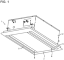
- FIG. 1 is a perspective view of the air-conditioning apparatus according to Embodiment 1 of the present invention.
- An air-conditioning apparatus 1 includes a housing 2 and a decorative panel 3.
- the housing 2 houses components such a fan and a heat exchanger that will descried later; the housing 2 is formed in the shape of a box having an opening portion on a lower side; and the housing 2 is provided in an opening formed in a ceiling.
- the decorative panel 3 is formed of a rectangular plate body, and is attached to the opening portion of the housing 2 in such a manner as to face an indoor space that is an air-conditioned space.
- the decorative panel 3 has air inlets 4 and air outlets 5, and the air inlets 4 extend along long sides of the decorative panel 3 to allow indoor air to be sucked.
- the air inlets 4 are inlets through which indoor air is sucked along the long sides thereof, and air outlets 5 are located outward of the respective air inlets 4 and allow air conditioned in the air-conditioning apparatus 1 to blow out to the indoor space.
- the air-conditioning apparatus 1 is connected to an outdoor unit (not illustrated) by a refrigerant pipe and circulates refrigerant between the air-conditioning apparatus 1 and the outdoor unit.
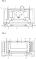
- Fig. 2 is a top view of the air-conditioning apparatus as illustrated in Fig. 1 .
- Fig. 2 is a view of the housing 2 that is obtained as viewed from above, with an upper surface of the housing 2 removed from the housing 2.
- the housing 2 has a first space 20 in which a fan 21 and a heat exchanger 22 are provided and a second space 30 in which a refrigerant sensor 31 and a pipe (not illustrated) are provided.
- the first space 20 and the second space 30 are adjacent to each other in parallel with a surface of the ceiling and along the air inlets 4 and the air outlets 5.
- the first space 20 and the second space 30 are partitioned off by a partition plate 10.
- the heat exchanger 22 causes heat exchange to be performed between air sucked by the fan 21 and refrigerant, and is provided downstream of the fan 21 in the flow of air and in such a manner as to surround the fan 21.
- the heat exchanger 22 is, for example, a finned tube heat exchanger.
- the partition plate 10 partitions off the first space 20 in which the fan 21 and the heat exchanger 22 are located and the second space 30 in which the refrigerant sensor 31 and the pipe (not illustrated) are located.
- a rectangular opening portion 11 is formed in the partition plate 10.
- the opening portion 11 has, for example, a length of approximately 30 to 40 cm in a horizontal direction and a length of approximately 10 to 15 cm in a vertical direction.
- the opening portion 11 is closed by a maintenance panel 12.
- the maintenance panel 12 has a size greater than or nearly equal to the size of the opening portion 11.
- the maintenance panel 12 is detachably attached to the partition plate 10 by, for example, screws.
- the maintenance panel 12 is detached for cleaning of the fan 21 or maintenance of a drain pan provided below the heat exchanger 22.
- the maintenance panel 12 is attached to the partition plate 10 to close the opening portion 11.
- the pressure of air from the fan 21 is higher than that at the portion where the air outlet port 14 is formed. It is therefore possible to cause some of air sucked into the first space 20 to flow into the second space 30 through the air inlet port 13.
- the refrigerant sensor 31 is provided in the second space 30 and is configured to detect whether refrigerant is contained in air in the second space 30 or not. To detect refrigerant efficiently, preferably, the refrigerant sensor 31 should be provided at a position in the second space 30 where refrigerant easily collects. Thus, the refrigerant sensor 31 is provided in a lower region in the second space 30 and closer to the air outlet port 14 than to the air inlet port 13.
- high-temperature and high-pressure gas refrigerant discharged from the compressor after being obtained by compression by the compressor flows into the heat exchanger 22 (condenser) via the four-way valve.
- the gas refrigerant that has flowed into the heat exchanger 22 exchanges heat with indoor air sent by the fan 21 to condense into low-temperature refrigerant, and then the low-temperature refrigerant flows out of the heat exchanger 22.
- the indoor air receives heat from the refrigerant and is thus heated, and is then blown out as warm air into the indoor space.
- the air inlet port 13 is formed at a location where the pressure of air from the fan 21 is higher than that at the air outlet port 14. Because of this configuration, the air containing refrigerant in the first space 20 easily flows into the second space 30, in which the refrigerant sensor 31 is provided, through the air inlet port 13.
- the air inlet port 13 is provided in the lower portion of the partition plate 10. Because of this configuration, since R32 refrigerant adopted in Embodiment 1 has a higher specific gravity than that of air, the concentration of refrigerant in a lower region of the air-conditioning apparatus is higher and air that contains refrigerant such that the concentration of the refrigerant is higher can thus be made to flow into the second space 30.
- the air outlet port 14 is provided in the upper portion of the partition plate 10. Because of this configuration, since the R32 refrigerant adopted in Embodiment 1 has a higher specific gravity than that of air, and the concentration of the refrigerant in an upper region in the air-conditioning apparatus 1 is lower, and air that contains refrigerant such that the concentration of the refrigerant is lower can be made to flow into the first space 20. That is, the air inlet port 13 is provided at a lower location than the air outlet port 14, and the concentration of the refrigerant in the second space 30 can thus be increased, and the accuracy of refrigerant detection by the refrigerant sensor 31 can be improved.
- the area of the air inlet port 13 be larger than that of the air outlet port 14. Because of this configuration, air containing refrigerant in the first space 20 easily flows into the second space 30, and the air containing refrigerant does not easily flow from the second space 30 into the first space 20; that is, the air containing refrigerant can be stayed in the second space 30 and the accuracy of refrigerant detection by the refrigerant sensor 31 can be improved.
- the refrigerant sensor 31 is provided in the lower region in the second space 30. Because of this configuration, the accuracy of the refrigerant detection can be improved, since the R32 refrigerant adopted in Embodiment 1 has a specific gravity higher than that of air, and the concentration of the refrigerant in a lower region in the air-conditioning apparatus 1 is thus higher.
- the refrigerant sensor 31 is provided closer to the air outlet port 14 than to the air inlet port 13. This location is not easily affected by air from the air inlet port 13, and air gently flows at the location. It is therefore possible to improve the accuracy of refrigerant detection.
- the refrigerant sensor 31 be provided below the air outlet port 14 and adjacent to the partition plate 10.
- the refrigerant sensor 31 is provided at a position where refrigerant easily collects. It should be noted that the refrigerant sensor 31 does not need to be completely adjacent to the partition plate 10, and it suffices that the refrigerant sensor 31 is provided in the vicinity of the partition plate 10.
- the air-conditioning apparatus 1 includes the housing 2 in which the first space 20 and the second space 30 are provided adjacent to each other, and that includes: the fan 21 that is provided in the first space 20 and sucks air into the housing 2; the heat exchanger 22 that is provided in the first space 20 and causes heat exchange to be performed between air sucked by the fan 21 and refrigerant; the refrigerant sensor 31 that is provided in the second space 30 and detects refrigerant; and the partition plate 10 that partitions off the first space 20 and the second space 30 and has the air inlet port 13 and the air outlet port 14.
- air containing refrigerant in the first space 20 easily flows into the second space 30 in which the refrigerant sensor 31 is provided, through the air inlet port 13.
- the refrigerant has a higher specific gravity than that of air
- the refrigerant sensor 31 is provided in the lower region in the second space 30, and the air inlet port 13 is provided below the air outlet port 14.
- the refrigerant concentration in the second space 30 can be increased, and the accuracy of refrigerant detection by the refrigerant sensor 31 can be improved, because an R32 refrigerant has a higher specific gravity than that of air and the refrigerant concentration in the lower region in the air-conditioning apparatus 1 is increased.
- the area of the air inlet port 13 is larger than the area of the air outlet port 14.
- the refrigerant sensor 31 is provided closer to the air outlet port 14 than to the air inlet port 13, and located below the air outlet port 14.
- the refrigerant sensor 31 is provided adjacent to the partition plate 10.
- Embodiment 1 can be variously modified or improved without departing from the subject matter of the present invention, as long as such modified or improved embodiments also fall within the technical scope of the present invention that is defined by the appended claims.
- Embodiment 1 a two-way blowing type indoor unit is described above as the air-conditioning apparatus 1, an indoor unit having air outlets in four directions may be used.
Landscapes
- Engineering & Computer Science (AREA)
- Chemical & Material Sciences (AREA)
- Combustion & Propulsion (AREA)
- Mechanical Engineering (AREA)
- General Engineering & Computer Science (AREA)
- Air Conditioning Control Device (AREA)
Claims (5)
- Klimatisierungsvorrichtung (1), aufweisend:ein Gehäuse (2) mit einem ersten Raum (20) und einem zweiten Raum (30), die benachbart zueinander sind;einen Ventilator (21), der in dem ersten Raum (20) vorgesehen ist und dazu ausgebildet ist, Luft in das Gehäuse (2) hinein zu saugen;einen Wärmetauscher (22), der in dem ersten Raum (20) vorgesehen ist und dazu ausgebildet ist, einen Wärmeaustausch zwischen der von dem Ventilator (21) angesaugten Luft und einem Kältemittel zu bewirken;einen Kältemittelsensor (31), der in dem zweiten Raum (30) vorgesehen ist und dazu eingerichtet ist, das Kältemittel zu detektieren; undeine Trennplatte (10), die vorgesehen ist, um den ersten Raum (20) und den zweiten Raum (30) voneinander zu trennen,wobei das Kältemittel eine höhere relative Dichte als Luft aufweist,wobei der Kältemittelsensor (31) in einer unteren Region in dem zweiten Raum (30) vorgesehen ist,dadurch gekennzeichnet, dass die Trennplatte (10) eine Lufteinlassöffnung (13) und eine Luftauslassöffnung (14) aufweist, wobei die Lufteinlassöffnung (13) unterhalb der Luftauslassöffnung (14) vorgesehen ist.
- Klimatisierungsvorrichtung (1) nach Anspruch 1, wobei die Lufteinlassöffnung (13) an einem Ort vorgesehen ist, an dem ein Druck der Luft von dem Ventilator (21) höher ist als an der Luftauslassöffnung (14).
- Klimatisierungsvorrichtung (1) nach Anspruch 1 oder 2, wobei eine Fläche der Lufteinlassöffnung (13) größer ist als eine Fläche der Luftauslassöffnung (14).
- Klimatisierungsvorrichtung (1) nach einem der Ansprüche 1 bis 3, wobei der Kältemittelsensor (31) näher an der Luftauslassöffnung (14) als an der Lufteinlassöffnung (13) vorgesehen ist und unterhalb der Luftauslassöffnung (14) angeordnet ist.
- Klimatisierungsvorrichtung (1) nach Anspruch 4, wobei der Kältemittelsensor (31) benachbart zu der Trennplatte (10) vorgesehen ist.
Applications Claiming Priority (1)
| Application Number | Priority Date | Filing Date | Title |
|---|---|---|---|
| PCT/JP2019/000377 WO2020144769A1 (ja) | 2019-01-09 | 2019-01-09 | 空気調和装置 |
Publications (3)
| Publication Number | Publication Date |
|---|---|
| EP3910258A1 EP3910258A1 (de) | 2021-11-17 |
| EP3910258A4 EP3910258A4 (de) | 2022-01-19 |
| EP3910258B1 true EP3910258B1 (de) | 2024-10-23 |
Family
ID=71521543
Family Applications (1)
| Application Number | Title | Priority Date | Filing Date |
|---|---|---|---|
| EP19908805.5A Active EP3910258B1 (de) | 2019-01-09 | 2019-01-09 | Klimatisierungsvorrichtung |
Country Status (4)
| Country | Link |
|---|---|
| US (1) | US11976829B2 (de) |
| EP (1) | EP3910258B1 (de) |
| JP (1) | JP6991369B2 (de) |
| WO (1) | WO2020144769A1 (de) |
Families Citing this family (2)
| Publication number | Priority date | Publication date | Assignee | Title |
|---|---|---|---|---|
| JP2022086972A (ja) * | 2020-11-30 | 2022-06-09 | パナソニックIpマネジメント株式会社 | 空気調和装置の室内ユニット |
| WO2025187031A1 (ja) * | 2024-03-08 | 2025-09-12 | 三菱電機株式会社 | 室内機、および空気調和機 |
Family Cites Families (17)
| Publication number | Priority date | Publication date | Assignee | Title |
|---|---|---|---|---|
| JP2012220163A (ja) * | 2011-04-13 | 2012-11-12 | Mitsubishi Heavy Ind Ltd | 空気調和機 |
| JP5818849B2 (ja) * | 2013-08-26 | 2015-11-18 | 三菱電機株式会社 | 空気調和装置および冷媒漏洩検知方法 |
| JP5665937B1 (ja) * | 2013-09-13 | 2015-02-04 | 三菱電機株式会社 | 冷凍サイクル装置 |
| JP6177158B2 (ja) * | 2014-02-25 | 2017-08-09 | ジョンソンコントロールズ ヒタチ エア コンディショニング テクノロジー(ホンコン)リミテッド | 空気調和機 |
| JP6452961B2 (ja) | 2014-06-05 | 2019-01-16 | 日立ジョンソンコントロールズ空調株式会社 | 空気調和機 |
| US10060645B2 (en) * | 2014-06-19 | 2018-08-28 | Mitsubishi Electric Corporation | Indoor unit of air-conditioning apparatus and air-conditioning apparatus including the indoor unit |
| JP6412395B2 (ja) | 2014-10-14 | 2018-10-24 | 日立ジョンソンコントロールズ空調株式会社 | 空気調和機の室内機 |
| US10760839B2 (en) * | 2015-03-26 | 2020-09-01 | Mitsubishi Electric Corporation | Indoor unit of air-conditioning apparatus having leaked refrigerant ventilation |
| WO2016151641A1 (ja) | 2015-03-26 | 2016-09-29 | 三菱電機株式会社 | 空気調和機の室内機 |
| JP6468347B2 (ja) * | 2015-03-31 | 2019-02-13 | ダイキン工業株式会社 | 空気調和装置 |
| JP6519360B2 (ja) | 2015-07-01 | 2019-05-29 | ダイキン工業株式会社 | 空気調和装置の室内機 |
| JP2017053514A (ja) * | 2015-09-08 | 2017-03-16 | ジョンソンコントロールズ ヒタチ エア コンディショニング テクノロジー(ホンコン)リミテッド | 空気調和機 |
| JP6555293B2 (ja) * | 2017-03-31 | 2019-08-07 | ダイキン工業株式会社 | 冷凍装置の室内ユニット |
| WO2018198165A1 (ja) * | 2017-04-24 | 2018-11-01 | 三菱電機株式会社 | 冷媒検知装置及び空気調和装置の室内機 |
| AU2017418267B2 (en) * | 2017-06-15 | 2020-10-29 | Mitsubishi Electric Corporation | Air-conditioning apparatus |
| JP6658687B2 (ja) * | 2017-07-10 | 2020-03-04 | ダイキン工業株式会社 | 冷媒検知センサを有する空気調和装置の室内ユニット |
| DE112018006844B4 (de) * | 2018-01-12 | 2023-10-19 | Mitsubishi Electric Corporation | Klimaanlage |
-
2019
- 2019-01-09 JP JP2020565073A patent/JP6991369B2/ja active Active
- 2019-01-09 WO PCT/JP2019/000377 patent/WO2020144769A1/ja not_active Ceased
- 2019-01-09 EP EP19908805.5A patent/EP3910258B1/de active Active
- 2019-01-09 US US17/289,390 patent/US11976829B2/en active Active
Also Published As
| Publication number | Publication date |
|---|---|
| EP3910258A4 (de) | 2022-01-19 |
| EP3910258A1 (de) | 2021-11-17 |
| JPWO2020144769A1 (ja) | 2021-09-09 |
| JP6991369B2 (ja) | 2022-01-12 |
| US20220003444A1 (en) | 2022-01-06 |
| WO2020144769A1 (ja) | 2020-07-16 |
| US11976829B2 (en) | 2024-05-07 |
Similar Documents
| Publication | Publication Date | Title |
|---|---|---|
| US11940162B2 (en) | Integrated air conditioner | |
| US10408484B2 (en) | Air-conditioning apparatus with a refrigerant leak sensor in an indoor unit | |
| CN114127478B (zh) | 冷冻装置的室内机 | |
| JP5818849B2 (ja) | 空気調和装置および冷媒漏洩検知方法 | |
| JP6785883B2 (ja) | 空気調和装置 | |
| CN107208954A (zh) | 空调装置 | |
| JP7518418B2 (ja) | 空調ユニット | |
| EP3910258B1 (de) | Klimatisierungsvorrichtung | |
| US10330357B2 (en) | Air conditioner and cooling receiver of air conditioner | |
| US20250257918A1 (en) | Refrigerant leak mitigation for multi-circuit refrigerant systems | |
| WO2018055726A1 (ja) | 天吊型空気調和装置 | |
| JP2021139581A (ja) | 床置き型空調室内機 | |
| KR101498621B1 (ko) | 공기조화 시스템 | |
| US20250020341A1 (en) | Outdoor unit of air conditioner and air conditioner including the same | |
| US20250020339A1 (en) | Outdoor unit of air conditioner and air conditioner including the same | |
| JP5992735B2 (ja) | 空気調和機 | |
| EP4641099A1 (de) | Ausseneinheit einer klimaanlage und klimaanlage damit | |
| JPS5916177B2 (ja) | 空気調和装置 | |
| JP7825174B2 (ja) | 熱媒体循環装置 | |
| US20250102161A1 (en) | Outdoor unit of air conditioner and manufacturing method thereof | |
| WO2025243417A1 (ja) | 冷凍サイクル装置 | |
| CN100375867C (zh) | 家庭用中央空调器 | |
| JP2004298309A (ja) | オープンショーケース | |
| CN105318508A (zh) | 空调装置 |
Legal Events
| Date | Code | Title | Description |
|---|---|---|---|
| STAA | Information on the status of an ep patent application or granted ep patent |
Free format text: STATUS: THE INTERNATIONAL PUBLICATION HAS BEEN MADE |
|
| PUAI | Public reference made under article 153(3) epc to a published international application that has entered the european phase |
Free format text: ORIGINAL CODE: 0009012 |
|
| STAA | Information on the status of an ep patent application or granted ep patent |
Free format text: STATUS: REQUEST FOR EXAMINATION WAS MADE |
|
| 17P | Request for examination filed |
Effective date: 20210518 |
|
| AK | Designated contracting states |
Kind code of ref document: A1 Designated state(s): AL AT BE BG CH CY CZ DE DK EE ES FI FR GB GR HR HU IE IS IT LI LT LU LV MC MK MT NL NO PL PT RO RS SE SI SK SM TR |
|
| A4 | Supplementary search report drawn up and despatched |
Effective date: 20211220 |
|
| RIC1 | Information provided on ipc code assigned before grant |
Ipc: F25B 49/02 20060101ALI20211214BHEP Ipc: F24F 11/36 20180101AFI20211214BHEP |
|
| DAV | Request for validation of the european patent (deleted) | ||
| DAX | Request for extension of the european patent (deleted) | ||
| REG | Reference to a national code |
Ref legal event code: R079 Free format text: PREVIOUS MAIN CLASS: F24F0011360000 Ipc: F24F0001001400 Ref country code: DE Ref document number: 602019060960 Country of ref document: DE |
|
| GRAP | Despatch of communication of intention to grant a patent |
Free format text: ORIGINAL CODE: EPIDOSNIGR1 |
|
| STAA | Information on the status of an ep patent application or granted ep patent |
Free format text: STATUS: GRANT OF PATENT IS INTENDED |
|
| RIC1 | Information provided on ipc code assigned before grant |
Ipc: F24F 11/36 20180101ALI20240430BHEP Ipc: F25B 49/00 20060101ALI20240430BHEP Ipc: F25B 13/00 20060101ALI20240430BHEP Ipc: F24F 13/06 20060101ALI20240430BHEP Ipc: F24F 1/0047 20190101ALI20240430BHEP Ipc: F24F 1/0014 20190101AFI20240430BHEP |
|
| INTG | Intention to grant announced |
Effective date: 20240517 |
|
| GRAS | Grant fee paid |
Free format text: ORIGINAL CODE: EPIDOSNIGR3 |
|
| GRAA | (expected) grant |
Free format text: ORIGINAL CODE: 0009210 |
|
| STAA | Information on the status of an ep patent application or granted ep patent |
Free format text: STATUS: THE PATENT HAS BEEN GRANTED |
|
| AK | Designated contracting states |
Kind code of ref document: B1 Designated state(s): AL AT BE BG CH CY CZ DE DK EE ES FI FR GB GR HR HU IE IS IT LI LT LU LV MC MK MT NL NO PL PT RO RS SE SI SK SM TR |
|
| REG | Reference to a national code |
Ref country code: GB Ref legal event code: FG4D |
|
| REG | Reference to a national code |
Ref country code: CH Ref legal event code: EP |
|
| REG | Reference to a national code |
Ref country code: DE Ref legal event code: R096 Ref document number: 602019060960 Country of ref document: DE |
|
| REG | Reference to a national code |
Ref country code: IE Ref legal event code: FG4D |
|
| REG | Reference to a national code |
Ref country code: LT Ref legal event code: MG9D |
|
| REG | Reference to a national code |
Ref country code: NL Ref legal event code: MP Effective date: 20241023 |
|
| REG | Reference to a national code |
Ref country code: AT Ref legal event code: MK05 Ref document number: 1735132 Country of ref document: AT Kind code of ref document: T Effective date: 20241023 |
|
| PG25 | Lapsed in a contracting state [announced via postgrant information from national office to epo] |
Ref country code: NL Free format text: LAPSE BECAUSE OF FAILURE TO SUBMIT A TRANSLATION OF THE DESCRIPTION OR TO PAY THE FEE WITHIN THE PRESCRIBED TIME-LIMIT Effective date: 20241023 |
|
| PG25 | Lapsed in a contracting state [announced via postgrant information from national office to epo] |
Ref country code: NL Free format text: LAPSE BECAUSE OF FAILURE TO SUBMIT A TRANSLATION OF THE DESCRIPTION OR TO PAY THE FEE WITHIN THE PRESCRIBED TIME-LIMIT Effective date: 20241023 |
|
| PG25 | Lapsed in a contracting state [announced via postgrant information from national office to epo] |
Ref country code: HR Free format text: LAPSE BECAUSE OF FAILURE TO SUBMIT A TRANSLATION OF THE DESCRIPTION OR TO PAY THE FEE WITHIN THE PRESCRIBED TIME-LIMIT Effective date: 20241023 Ref country code: IS Free format text: LAPSE BECAUSE OF FAILURE TO SUBMIT A TRANSLATION OF THE DESCRIPTION OR TO PAY THE FEE WITHIN THE PRESCRIBED TIME-LIMIT Effective date: 20250223 Ref country code: PT Free format text: LAPSE BECAUSE OF FAILURE TO SUBMIT A TRANSLATION OF THE DESCRIPTION OR TO PAY THE FEE WITHIN THE PRESCRIBED TIME-LIMIT Effective date: 20250224 |
|
| PGFP | Annual fee paid to national office [announced via postgrant information from national office to epo] |
Ref country code: DE Payment date: 20241217 Year of fee payment: 7 |
|
| PG25 | Lapsed in a contracting state [announced via postgrant information from national office to epo] |
Ref country code: FI Free format text: LAPSE BECAUSE OF FAILURE TO SUBMIT A TRANSLATION OF THE DESCRIPTION OR TO PAY THE FEE WITHIN THE PRESCRIBED TIME-LIMIT Effective date: 20241023 |
|
| PG25 | Lapsed in a contracting state [announced via postgrant information from national office to epo] |
Ref country code: BG Free format text: LAPSE BECAUSE OF FAILURE TO SUBMIT A TRANSLATION OF THE DESCRIPTION OR TO PAY THE FEE WITHIN THE PRESCRIBED TIME-LIMIT Effective date: 20241023 |
|
| PG25 | Lapsed in a contracting state [announced via postgrant information from national office to epo] |
Ref country code: ES Free format text: LAPSE BECAUSE OF FAILURE TO SUBMIT A TRANSLATION OF THE DESCRIPTION OR TO PAY THE FEE WITHIN THE PRESCRIBED TIME-LIMIT Effective date: 20241023 |
|
| PG25 | Lapsed in a contracting state [announced via postgrant information from national office to epo] |
Ref country code: NO Free format text: LAPSE BECAUSE OF FAILURE TO SUBMIT A TRANSLATION OF THE DESCRIPTION OR TO PAY THE FEE WITHIN THE PRESCRIBED TIME-LIMIT Effective date: 20250123 |
|
| PG25 | Lapsed in a contracting state [announced via postgrant information from national office to epo] |
Ref country code: AT Free format text: LAPSE BECAUSE OF FAILURE TO SUBMIT A TRANSLATION OF THE DESCRIPTION OR TO PAY THE FEE WITHIN THE PRESCRIBED TIME-LIMIT Effective date: 20241023 Ref country code: GR Free format text: LAPSE BECAUSE OF FAILURE TO SUBMIT A TRANSLATION OF THE DESCRIPTION OR TO PAY THE FEE WITHIN THE PRESCRIBED TIME-LIMIT Effective date: 20250124 Ref country code: LV Free format text: LAPSE BECAUSE OF FAILURE TO SUBMIT A TRANSLATION OF THE DESCRIPTION OR TO PAY THE FEE WITHIN THE PRESCRIBED TIME-LIMIT Effective date: 20241023 |
|
| PG25 | Lapsed in a contracting state [announced via postgrant information from national office to epo] |
Ref country code: PL Free format text: LAPSE BECAUSE OF FAILURE TO SUBMIT A TRANSLATION OF THE DESCRIPTION OR TO PAY THE FEE WITHIN THE PRESCRIBED TIME-LIMIT Effective date: 20241023 |
|
| PG25 | Lapsed in a contracting state [announced via postgrant information from national office to epo] |
Ref country code: RS Free format text: LAPSE BECAUSE OF FAILURE TO SUBMIT A TRANSLATION OF THE DESCRIPTION OR TO PAY THE FEE WITHIN THE PRESCRIBED TIME-LIMIT Effective date: 20250123 |
|
| PG25 | Lapsed in a contracting state [announced via postgrant information from national office to epo] |
Ref country code: SM Free format text: LAPSE BECAUSE OF FAILURE TO SUBMIT A TRANSLATION OF THE DESCRIPTION OR TO PAY THE FEE WITHIN THE PRESCRIBED TIME-LIMIT Effective date: 20241023 |
|
| PG25 | Lapsed in a contracting state [announced via postgrant information from national office to epo] |
Ref country code: DK Free format text: LAPSE BECAUSE OF FAILURE TO SUBMIT A TRANSLATION OF THE DESCRIPTION OR TO PAY THE FEE WITHIN THE PRESCRIBED TIME-LIMIT Effective date: 20241023 |
|
| PG25 | Lapsed in a contracting state [announced via postgrant information from national office to epo] |
Ref country code: EE Free format text: LAPSE BECAUSE OF FAILURE TO SUBMIT A TRANSLATION OF THE DESCRIPTION OR TO PAY THE FEE WITHIN THE PRESCRIBED TIME-LIMIT Effective date: 20241023 |
|
| PG25 | Lapsed in a contracting state [announced via postgrant information from national office to epo] |
Ref country code: RO Free format text: LAPSE BECAUSE OF FAILURE TO SUBMIT A TRANSLATION OF THE DESCRIPTION OR TO PAY THE FEE WITHIN THE PRESCRIBED TIME-LIMIT Effective date: 20241023 |
|
| REG | Reference to a national code |
Ref country code: DE Ref legal event code: R097 Ref document number: 602019060960 Country of ref document: DE |
|
| PG25 | Lapsed in a contracting state [announced via postgrant information from national office to epo] |
Ref country code: SK Free format text: LAPSE BECAUSE OF FAILURE TO SUBMIT A TRANSLATION OF THE DESCRIPTION OR TO PAY THE FEE WITHIN THE PRESCRIBED TIME-LIMIT Effective date: 20241023 |
|
| PG25 | Lapsed in a contracting state [announced via postgrant information from national office to epo] |
Ref country code: CZ Free format text: LAPSE BECAUSE OF FAILURE TO SUBMIT A TRANSLATION OF THE DESCRIPTION OR TO PAY THE FEE WITHIN THE PRESCRIBED TIME-LIMIT Effective date: 20241023 |
|
| PG25 | Lapsed in a contracting state [announced via postgrant information from national office to epo] |
Ref country code: IT Free format text: LAPSE BECAUSE OF FAILURE TO SUBMIT A TRANSLATION OF THE DESCRIPTION OR TO PAY THE FEE WITHIN THE PRESCRIBED TIME-LIMIT Effective date: 20241023 |
|
| PLBE | No opposition filed within time limit |
Free format text: ORIGINAL CODE: 0009261 |
|
| REG | Reference to a national code |
Ref country code: CH Ref legal event code: PL |
|
| STAA | Information on the status of an ep patent application or granted ep patent |
Free format text: STATUS: NO OPPOSITION FILED WITHIN TIME LIMIT |
|
| PG25 | Lapsed in a contracting state [announced via postgrant information from national office to epo] |
Ref country code: SE Free format text: LAPSE BECAUSE OF FAILURE TO SUBMIT A TRANSLATION OF THE DESCRIPTION OR TO PAY THE FEE WITHIN THE PRESCRIBED TIME-LIMIT Effective date: 20241023 |
|
| PG25 | Lapsed in a contracting state [announced via postgrant information from national office to epo] |
Ref country code: LU Free format text: LAPSE BECAUSE OF NON-PAYMENT OF DUE FEES Effective date: 20250109 Ref country code: MC Free format text: LAPSE BECAUSE OF FAILURE TO SUBMIT A TRANSLATION OF THE DESCRIPTION OR TO PAY THE FEE WITHIN THE PRESCRIBED TIME-LIMIT Effective date: 20241023 |
|
| 26N | No opposition filed |
Effective date: 20250724 |
|
| P01 | Opt-out of the competence of the unified patent court (upc) registered |
Free format text: CASE NUMBER: UPC_APP_4937_3910258/2025 Effective date: 20250827 |
|
| PG25 | Lapsed in a contracting state [announced via postgrant information from national office to epo] |
Ref country code: BE Free format text: LAPSE BECAUSE OF NON-PAYMENT OF DUE FEES Effective date: 20250131 |
|
| PG25 | Lapsed in a contracting state [announced via postgrant information from national office to epo] |
Ref country code: FR Free format text: LAPSE BECAUSE OF NON-PAYMENT OF DUE FEES Effective date: 20250131 |
|
| PG25 | Lapsed in a contracting state [announced via postgrant information from national office to epo] |
Ref country code: CH Free format text: LAPSE BECAUSE OF NON-PAYMENT OF DUE FEES Effective date: 20250131 |
|
| REG | Reference to a national code |
Ref country code: BE Ref legal event code: MM Effective date: 20250131 |
|
| PGFP | Annual fee paid to national office [announced via postgrant information from national office to epo] |
Ref country code: GB Payment date: 20251127 Year of fee payment: 8 |
|
| PG25 | Lapsed in a contracting state [announced via postgrant information from national office to epo] |
Ref country code: IE Free format text: LAPSE BECAUSE OF NON-PAYMENT OF DUE FEES Effective date: 20250109 |