EP3907124B1 - Vehicle roof structure - Google Patents
Vehicle roof structure Download PDFInfo
- Publication number
- EP3907124B1 EP3907124B1 EP20766698.3A EP20766698A EP3907124B1 EP 3907124 B1 EP3907124 B1 EP 3907124B1 EP 20766698 A EP20766698 A EP 20766698A EP 3907124 B1 EP3907124 B1 EP 3907124B1
- Authority
- EP
- European Patent Office
- Prior art keywords
- roof
- annular frame
- panel
- vehicle
- roof structure
- Prior art date
- Legal status (The legal status is an assumption and is not a legal conclusion. Google has not performed a legal analysis and makes no representation as to the accuracy of the status listed.)
- Active
Links
- 239000000835 fiber Substances 0.000 claims description 41
- 229920005989 resin Polymers 0.000 claims description 14
- 239000011347 resin Substances 0.000 claims description 14
- 229920003002 synthetic resin Polymers 0.000 claims description 10
- 239000000057 synthetic resin Substances 0.000 claims description 10
- 239000000853 adhesive Substances 0.000 description 9
- 230000001070 adhesive effect Effects 0.000 description 9
- 238000005452 bending Methods 0.000 description 9
- 239000004918 carbon fiber reinforced polymer Substances 0.000 description 6
- 239000002356 single layer Substances 0.000 description 4
- 239000000463 material Substances 0.000 description 3
- 229920000049 Carbon (fiber) Polymers 0.000 description 2
- 229910000831 Steel Inorganic materials 0.000 description 2
- 239000004917 carbon fiber Substances 0.000 description 2
- 230000035699 permeability Effects 0.000 description 2
- 239000010959 steel Substances 0.000 description 2
- 230000008878 coupling Effects 0.000 description 1
- 238000010168 coupling process Methods 0.000 description 1
- 238000005859 coupling reaction Methods 0.000 description 1
- 239000003365 glass fiber Substances 0.000 description 1
- 239000003292 glue Substances 0.000 description 1
- 239000010410 layer Substances 0.000 description 1
- VNWKTOKETHGBQD-UHFFFAOYSA-N methane Chemical compound C VNWKTOKETHGBQD-UHFFFAOYSA-N 0.000 description 1
- 229920003023 plastic Polymers 0.000 description 1
- 230000003014 reinforcing effect Effects 0.000 description 1
- 238000007789 sealing Methods 0.000 description 1
- 238000010008 shearing Methods 0.000 description 1
- XLYOFNOQVPJJNP-UHFFFAOYSA-N water Substances O XLYOFNOQVPJJNP-UHFFFAOYSA-N 0.000 description 1
- 238000003466 welding Methods 0.000 description 1
Images


Classifications
-
- B—PERFORMING OPERATIONS; TRANSPORTING
- B62—LAND VEHICLES FOR TRAVELLING OTHERWISE THAN ON RAILS
- B62D—MOTOR VEHICLES; TRAILERS
- B62D25/00—Superstructure or monocoque structure sub-units; Parts or details thereof not otherwise provided for
- B62D25/06—Fixed roofs
-
- B—PERFORMING OPERATIONS; TRANSPORTING
- B62—LAND VEHICLES FOR TRAVELLING OTHERWISE THAN ON RAILS
- B62D—MOTOR VEHICLES; TRAILERS
- B62D29/00—Superstructures, understructures, or sub-units thereof, characterised by the material thereof
- B62D29/04—Superstructures, understructures, or sub-units thereof, characterised by the material thereof predominantly of synthetic material
-
- B—PERFORMING OPERATIONS; TRANSPORTING
- B60—VEHICLES IN GENERAL
- B60J—WINDOWS, WINDSCREENS, NON-FIXED ROOFS, DOORS, OR SIMILAR DEVICES FOR VEHICLES; REMOVABLE EXTERNAL PROTECTIVE COVERINGS SPECIALLY ADAPTED FOR VEHICLES
- B60J7/00—Non-fixed roofs; Roofs with movable panels, e.g. rotary sunroofs
- B60J7/02—Non-fixed roofs; Roofs with movable panels, e.g. rotary sunroofs of sliding type, e.g. comprising guide shoes
- B60J7/04—Non-fixed roofs; Roofs with movable panels, e.g. rotary sunroofs of sliding type, e.g. comprising guide shoes with rigid plate-like element or elements, e.g. open roofs with harmonica-type folding rigid panels
- B60J7/043—Sunroofs e.g. sliding above the roof
-
- B—PERFORMING OPERATIONS; TRANSPORTING
- B62—LAND VEHICLES FOR TRAVELLING OTHERWISE THAN ON RAILS
- B62D—MOTOR VEHICLES; TRAILERS
- B62D27/00—Connections between superstructure or understructure sub-units
- B62D27/02—Connections between superstructure or understructure sub-units rigid
-
- B—PERFORMING OPERATIONS; TRANSPORTING
- B62—LAND VEHICLES FOR TRAVELLING OTHERWISE THAN ON RAILS
- B62D—MOTOR VEHICLES; TRAILERS
- B62D29/00—Superstructures, understructures, or sub-units thereof, characterised by the material thereof
- B62D29/04—Superstructures, understructures, or sub-units thereof, characterised by the material thereof predominantly of synthetic material
- B62D29/043—Superstructures
-
- B—PERFORMING OPERATIONS; TRANSPORTING
- B62—LAND VEHICLES FOR TRAVELLING OTHERWISE THAN ON RAILS
- B62D—MOTOR VEHICLES; TRAILERS
- B62D27/00—Connections between superstructure or understructure sub-units
- B62D27/06—Connections between superstructure or understructure sub-units readily releasable
- B62D27/065—Connections between superstructure or understructure sub-units readily releasable using screwthread
Definitions
- the present invention relates to a vehicle roof structure.
- a roof reinforce member that is stretched between a pair of roof side rails is provided as a reinforcing member for a roof such that the roof bears a large load when another vehicle collides with a side portion of a vehicle (that is, a side collision).
- the roof structure disclosed in Patent Literature 1 includes a hollow rectangular frame 51 on an outer circumference of a roof of a vehicle body.
- This hollow rectangular frame 51 is a frame body having a hollow rectangular cross section.
- the hollow rectangular frame 51 is welded to these roof side rails 54 and the like.
- this hollow rectangular frame 51 reinforces the roof.
- the hollow rectangular frame 51 is welded to the roof side rails 54 vertically. Accordingly, when a large load is applied to one of the roof side rails 54 during a side collision of the vehicle, a large shearing force is applied to a welded portion to the hollow rectangular frame 51, which possibly damages the welded portion. As a result, there is a possibility that the load is no longer transmitted to the hollow rectangular frame 51. In this case, it is difficult to maintain side collision performance of the vehicle.
- Patent Literature 2 discloses a body of a motor vehicle, in which the lateral roof area has an outer skin, an outer roof frame and an inner roof frame, wherein the outer roof frame is arranged under the outer skin and the inner roof frame is arranged under the outer roof frame.
- Patent Literature 2 describes a vehicle roof structure according to the preamble of claim 1.
- Patent Literature 3 discloses a roof having an outer panel and a support frame connected to each other by a glue cord and by a mechanical connection extending on circumference of the panel and frame.
- Patent Literature 4 discloses a vehicle roof with a roof frame and a roof module, which is permanently and rigidly attached to the roof frame.
- Patent Literature 5 discloses the use of transparent plastics in vehicle exterior parts, in particular vehicle roofs, which is intended to help improve the interior lighting and increase safety through better all-round visibility.
- the present invention has been made in view of the above circumstance and therefore has a purpose of providing a vehicle roof structure capable of maintaining side collision performance of a vehicle even without providing a roof reinforce member.
- the vehicle roof structure according to the present invention is a roof structure that constitutes a roof of a vehicle and includes: a pair of roof side rails that is arranged to be separated in a width direction of a vehicle body and each constitute a framework of a side portion of the roof; a front header and a rear header that are arranged to be separated in a longitudinal direction of the vehicle body and respectively constitute frameworks in a front end portion and a rear end portion of the roof; a roof panel that covers an opening formed by the pair of roof side rails, the front header, and the rear header; and an annular frame that is joined to a circumferential edge of the roof panel and supports the roof panel.
- the annular frame has higher rigidity than the roof panel, is arranged in the opening, and is joined to the pair of roof side rails, the front header, and the rear header.
- the annular frame has a body portion that has a cross-sectional shape including: a panel joint portion that extends along a surface of the circumferential edge of the roof panel and is joined to said circumferential edge; and a vertical plate portion that extends from said panel joint portion in a vertical direction of the vehicle body.
- the body portion has a hollow closed cross-sectional shape that is formed by a pair of the panel joint portions and a pair of the vertical plate portions.
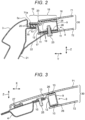
- a vehicle roof structure is a structure that constitutes a roof 2 of a vehicle, and includes: a pair of roof side rails 3 arranged to be separated in a width direction Y of a vehicle body 1; a front header 4 and a rear header 5 arranged to be separated in a longitudinal direction X of the vehicle body 1; and a panel unit 30.
- the pair of roof side rails 3, the front header 4, and the rear header 5 form a rectangular opening 6 of the roof 2, and the opening 6 is closed by the panel unit 30.
- the pair of roof side rails 3 are arranged to be separated in the width direction Y of the vehicle body 1 and each extend in the longitudinal direction X of the vehicle body 1 to constitute a frame in a side portion of the roof 2.
- the roof side rail 3 on each side has a flange portion 15 (see Fig. 2 ) that is projected into the opening 6.
- the front header 4 and the rear header 5 are arranged to be separated in the longitudinal direction X of the vehicle body 1 and extend in the width direction Y of the vehicle body 1 to respectively constitute frameworks in a front end portion and a rear end portion of the roof 2.
- Each of the front header 4 and the rear header 5 has the flange portion 15 (see Fig. 3 ) that is projected into the opening 6.
- the panel unit 30 includes a roof panel 7 and an annular frame 8.
- the roof panel 7 has a configuration capable of covering the opening 6, which is formed by the pair of roof side rails 3, the front header 4, and the rear header 5.
- the roof panel 7 in this embodiment is constructed of a double panel in which an outer panel 71 exposed to outside of the vehicle body 1 and an inner panel 72 located in the vehicle body 1 hold the annular frame 8 therebetween and are arranged to be separated in a vertical direction Z.
- the roof panel 7 may be a single roof panel or may only include the outer panel 71.
- Each of the outer panel 71 and the inner panel 72 constituting the roof panel 7 is made from a translucent or semi-translucent synthetic resin material having high rigidity (more specifically, high bending rigidity, twisting rigidity, and the like), for example, translucent FRP made from a translucent synthetic resin that is reinforced by glass fiber, and has translucency.
- a film for lighting control and heat shielding may adhere to an inner surface, which faces inside of the vehicle body 1, in each of the outer panel 71 and the inner panel 72.
- the inner panel 72 may be subjected to special treatment such that a desired color and/or pattern is appeared by transmitted light.
- the annular frame 8 has a configuration capable of supporting the roof panel 7 by being joined to an circumferential edge of the roof panel 7.
- the annular frame 8 is an annular frame body (more specifically, a substantially rectangular frame body as illustrated in Fig. 1 ) that is manufactured from a material (for example, a fiber reinforced resin such as a synthetic resin (CFRP) that is reinforced by a carbon fiber) having the higher rigidity (more specifically, the higher bending rigidity, the higher twisting rigidity, and the like) than the roof panel 7.
- a material for example, a fiber reinforced resin such as a synthetic resin (CFRP) that is reinforced by a carbon fiber
- CFRP synthetic resin
- the annular frame 8 is arranged in the opening 6 of the vehicle body 1 illustrated in Fig. 1 . As illustrated in Figs.
- the annular frame 8 is adjacent to and joined to each of the paired roof side rails 3 in the width direction Y, and is adjacent to and joined to the front header 4 and the rear header 5 in the longitudinal direction X.
- the annular frame 8 includes a body portion 9 and the fastening portion 13 that is integrally joined to the body portion 9.
- the body portion 9 has a cross-sectional shape having a hollow closed cross section that is formed by a pair of upper and lower panel joint portions 10 and a pair of vertical plate portions 11.
- the pair of upper and lower panel joint portions 10 extends in a direction toward the inside of the opening 6 of the roof 2 (that is, the width direction Y or the longitudinal direction X), extends along surfaces of circumferential edges of the outer panel 71 and the inner panel 72 of the roof panel 7, and is joined to the circumferential edges.
- the pair of vertical plate portions 11 extends from the panel joint portions 10 in the vertical direction Z of the vehicle body 1.
- the pair of panel joint portions 10 of the body portion 9 is arranged to be separated in the vertical direction Z, and firmly adheres to the outer panel 71 and the inner panel 72 by a high-rigid adhesive 26.
- the fastening portion 13 is projected from an outer circumferential surface of the body portion 9 in a direction toward the flange portion 15.
- the fastening portion 13 is fastened to each of the paired roof side rails 3, the front header 4, and the rear header 5 via the flange portion 15 that is projected into the opening 6.
- the similar high-rigid adhesive 26 to the above adheres the fastening portion 13 to an upper surface of each of the flange portions 15 extending from the roof side rails 3 and the like.
- an upper end 16 of the annular frame 8 is located in a substantially same height as an upper end 3a of the roof side rail 3. Furthermore, a lower end 17 of the annular frame 8 is located below the flange portion 15. In this way, it is possible to secure rigidity of the annular frame 8 while the height of the annular frame 8 is secured.
- a side edge portion 71a of the outer panel 71 extends to the fastening portion 13, is superimposed on an upper surface of the fastening portion 13, and is fastened thereto. Then, the side edge portion 71a and the fastening portion 13 are superimposed on the upper surface of the flange portion 15 of the roof side rail 3 and are fastened thereto.
- the above high-rigid adhesive 26 adheres between the side edge portion 71a and the fastening portion 13 and between the fastening portion 13 and the flange portion 15. In this way, it is possible to transmit a load that is received by the roof side rail 3 during a vehicle collision to the annular frame 8 and the roof panel 7 (more specifically, the outer panel 71) via the flange portion 15.
- the side edge portion 71a, the fastening portion 13, and the fastening portion 13 may collectively be fastened by a bolt, a rivet, or the like.
- a space 20 having a closed cross section is formed by the roof panel 7 and the annular frame 8, and is located between a portion 18 and a portion 19 of the outer panel 71 in the roof panel 7.
- the portion 18 is joined to the panel joint portion 10 of the body portion 9 in the annular frame 8.
- the portion 19 is a portion in which the side edge portion 71a of the outer panel 71 is fastened to the fastening portion 13. Since a portion that surrounds the space 20 having the closed cross section is formed by the outer panel 71 and the annular frame 8, it is possible to reinforce a portion around the fastening portion 13.
- the above space 20 having the closed cross section may be formed by the inner panel 72 and the annular frame 8.
- a coupling member called a gusset 22 is coupled to a portion below the flange portion 15 in the roof side rail 3 illustrated in Figs. 1 to 2 or a B pillar (center pillar) 21 coupled to a lower portion of the roof side rail 3 by welding or the like.
- the gusset 22 is coupled to the B pillar 21 and is indirectly coupled to the roof side rail 3 via the B pillar 21.
- An upper end portion of the gusset 22 is mechanically joined to the annular frame 8 and the inner panel 72 of the roof panel 7 by a bolt 23.
- the roof side rail 3 is coupled to the annular frame 8 by both of the flange portion 15 and the gusset 22. In this way, it is possible to efficiently transmit the load, which is received by the roof side rail 3 and the B pillar 21 during the side collision of the vehicle, to the annular frame 8 and both of the outer panel 71 of the inner panel 72 in the roof panel 7 via two routes of the flange portion 15 and the gusset 22.
- a caulking nut that is caulked and fixed to the annular frame 8 or the like, or the like may be used.
- the flange portion 15 of the front header 4 and the fastening portion 13 of the annular frame 8 are mechanically fastened by using a bolt 25.
- a bolt 25 for example, a caulking bolt that is caulked and fixed to the fastening portion 13, or the like may be used.
- the bolt 25 penetrates the flange portion 15 and is projected downward.
- a nut is fastened to the bolt 25 from a position below the flange portion 15.
- an end portion on a front side (a left side in Fig. 3 ) in the outer panel 71 extends to a position above the front header 4 and adheres to an upper surface of the front header 4 by an adhesive 27.
- an adhesive 27 a normal adhesive having such a sealing property that can prevent entry of rain water and the like into a clearance between the outer panel 71 and the front header 4 from the outside may be used.
- the body portion 9 of the annular frame 8 has a hollow closed cross-sectional shape and, for example, has the hollow rectangular cross-sectional shape as illustrated in Figs. 2 to 4 .
- the body portion 9 having the hollow closed cross-sectional shape is formed from a material that includes the synthetic resin such as the CFRP.
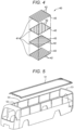
- the body portion 9 includes an annular sheet portion 12 that is formed from a fiber reinforced resin sheet bent in an annular shape.
- the annular sheet portion 12 is formed by bending a stacked sheet 40 illustrated in Fig. 4 in the annular shape and thereafter subjecting the stacked sheet 40 into hardening treatment.
- the stacked sheet 40 is an embodiment of the fiber reinforced resin sheet in the present invention, and is constructed of a stacked body of single-layer sheets 41, each of which is formed from the CFRP or the like.
- each of the single-layer sheets 41 that constitute the stacked sheet 40 is made from the CFRP, and is manufactured by impregnating plural reinforced fibers (carbon fibers in case of the CFRP) 42 with a synthetic resin 43 and covering the reinforced fibers 42 with the synthetic resin 43.
- the reinforced fibers 42 are long fibers that extend in parallel with each other.
- the stacked sheet 40 is constructed by stacking the plural single-layer sheets 41 in different directions such that extending directions of the reinforced fibers 42 in the single-layer sheets 41 differ from each other. In this way, the stacked sheet 40 can constitute the single fiber reinforced resin sheet including the reinforced fibers 42, which extend in the different directions from each other.
- the fiber reinforced resin sheet in the present invention may be formed by impregnating an intermediate body of the plural reinforced fibers 42 (for example, reinforced fibers being woven in a lattice shape), which are arranged in advance to extend in the different directions from each other, with the synthetic resin.
- the space 20 having the closed cross section is formed by the roof panel 7 and the annular frame 8, and is located between the portion 18, which is joined to the panel joint portion 10 of the body portion 9 in the annular frame 8, and the portion 19, in which the side edge portion 71a is fastened to the fastening portion 13, in the roof panel 7.
- the portion around the fastening portion 13 is reinforced by the portion surrounding this space 20 having the closed cross section.
- the roof panel 7 is translucent. With such a configuration, in this configuration, a degree of freedom in light permeability is increased due to absence of the roof reinforce member that is stretched between the pair of roof side rails 3.
- the vehicle roof structure according to the embodiment is the roof structure that constitutes the roof of the vehicle and includes: the pair of roof side rails that are arranged to be separated in the width direction of the vehicle body and each constitute the framework in the side portion of the roof; the front header and the rear header that are arranged to be separated in the longitudinal direction of the vehicle body and respectively constitute the frameworks in the front end portion and the rear end portion of the roof; the roof panel that covers the opening formed by the pair of roof side rails, the front header, and the rear header; and the annular frame that is joined to the circumferential edge of the roof panel and supports the roof panel.
- the annular frame has the higher rigidity than the roof panel, is arranged in the opening, and is joined to the pair of roof side rails, the front header, and the rear header.
- the annular frame which is joined to the circumferential edge of the roof panel and supports the roof panel, has the high rigidity.
- the annular frame In the state of being arranged in the opening, which is formed by the pair of roof side rails, the front header, and the rear header, the annular frame is joined to the pair of roof side rails, the front header, and the rear header.
- the annular frame has the body portion that has the cross-sectional shape including: the panel joint portions, each of which extends along the surface of the circumferential edge of the roof panel and is joined to the circumferential edge thereof; and the vertical plate portions, each of which extends from the panel joint portion in the vertical direction of the vehicle body.
- the body portion of the annular frame has the cross-sectional shape including: the panel joint portions, each of which extends along the surface of the circumferential edge of the roof panel; and the vertical plate portions, each of which extends in the vertical direction.
- the body portion has the hollow closed cross-sectional shape that is formed by the pair of the panel joint portions and the pair of the vertical plate portions.
- the annular frame is preferably formed from the fiber reinforced resin.
- the annular frame is formed from the fiber reinforced resin, compared to the frame that is made of steel, the annular frame is light in weight and has the high rigidity.
- the body portion preferably includes the annular sheet portion that is formed from the fiber reinforced resin sheet bent in the annular shape.
- the fiber reinforced resin sheet preferably includes: the plural reinforced fibers, each of which is the long fiber; and the synthetic resin that covers the plural reinforced fibers. At least some of the plural reinforced fibers preferably extend in the different direction.
- the fiber reinforced resin sheet which constitutes the annular sheet portion, includes the plural reinforced fibers as the long fibers extending in the different directions, and these reinforced fibers can receive the load from any of the different directions.
- the annular frame can obtain the bearing force against the collision in any direction including the side collision.
- the annular frame further preferably includes the fastening portion that is fastened to each of the paired roof side rails, the front header, and the rear header.
- the roof side rail preferably has the flange portion that is projected into the opening, and the fastening portion is preferably fastened to the flange portion.
- the upper end of the annular frame is preferably located in the substantially same height as the upper end of the roof side rail, and the lower end of the annular frame is preferably located below the flange portion.
- the annular frame is arranged such that the upper end of the annular frame is located in the substantially same height as the upper end of the roof side rail and that the lower end of the annular frame is located below the flange portion. In this way, it is possible to secure the height of the annular frame and to improve the rigidity of the annular frame.
- the roof panel preferably has the side edge portion that extends to the fastening portion and is fastened to the fastening portion.
- the side edge portion and the fastening portion are preferably fastened to the flange portion of the roof side rail.
- both of the side edge portion of the roof panel and the fastening portion of the annular frame are fastened to the flange portion of the roof side rail.
- the space having the closed cross section is preferably formed by the roof panel and the annular frame, and is preferably located between the portion, which is joined to the panel joint portion of the body portion in the annular frame, and the portion, in which the side edge portion is fastened to the fastening portion, in the roof panel.
- the space having the closed cross section is formed by the roof panel and the annular frame, and is located between the portion, which is joined to the panel joint portion of the body portion in the annular frame, and the portion, in which the side edge portion is fastened to the fastening portion, in the roof panel.
- the portion around the fastening portion is reinforced by the portion surrounding this space having the closed cross section.
- the roof panel is preferably translucent.
Applications Claiming Priority (2)
| Application Number | Priority Date | Filing Date | Title |
|---|---|---|---|
| JP2019040582A JP7205311B2 (ja) | 2019-03-06 | 2019-03-06 | 車両のルーフ構造 |
| PCT/JP2020/004974 WO2020179357A1 (ja) | 2019-03-06 | 2020-02-07 | 車両のルーフ構造 |
Publications (3)
| Publication Number | Publication Date |
|---|---|
| EP3907124A1 EP3907124A1 (en) | 2021-11-10 |
| EP3907124A4 EP3907124A4 (en) | 2022-03-23 |
| EP3907124B1 true EP3907124B1 (en) | 2023-08-09 |
Family
ID=72336895
Family Applications (1)
| Application Number | Title | Priority Date | Filing Date |
|---|---|---|---|
| EP20766698.3A Active EP3907124B1 (en) | 2019-03-06 | 2020-02-07 | Vehicle roof structure |
Country Status (5)
| Country | Link |
|---|---|
| US (1) | US11685445B2 (ja) |
| EP (1) | EP3907124B1 (ja) |
| JP (1) | JP7205311B2 (ja) |
| CN (1) | CN113508071B (ja) |
| WO (1) | WO2020179357A1 (ja) |
Families Citing this family (1)
| Publication number | Priority date | Publication date | Assignee | Title |
|---|---|---|---|---|
| ES2959319A1 (es) * | 2022-07-29 | 2024-02-23 | Seat Sa | Un conjunto de techo panorámico, un método de montaje del conjunto de techo panorámico y un vehículo equipado con el conjunto de techo panorámico |
Family Cites Families (14)
| Publication number | Priority date | Publication date | Assignee | Title |
|---|---|---|---|---|
| DE10158742B4 (de) * | 2001-11-30 | 2005-03-03 | Webasto Ag | Rahmenstruktur eines Fahrzeugdaches und Fahrzeugdach mit einer Rahmenstruktur |
| DE10200750B4 (de) * | 2002-01-10 | 2006-10-26 | Peguform Gmbh | Fahrzeugdach aus transparentem oder transluzentem Kunststoff |
| DE10254773B4 (de) * | 2002-11-22 | 2007-03-22 | Webasto Ag | Modulares Fahrzeugdach |
| DE10257398A1 (de) * | 2002-12-09 | 2004-06-24 | Arvinmeritor Gmbh | Fahrzeugdach |
| FR2869010B1 (fr) * | 2004-04-14 | 2007-07-20 | Peugeot Citroen Automobiles Sa | Toit de vehicule automobile et vehicule automobile comportant un tel toit |
| FR2882982B1 (fr) * | 2005-03-10 | 2009-05-01 | Heuliez Sa | Caisse, vehicule pourvu d'une telle caisse avec un pavillon et procede de fabrication |
| JP4887991B2 (ja) | 2006-09-14 | 2012-02-29 | マツダ株式会社 | 車両の樹脂ルーフ構造 |
| DE102007042277B4 (de) * | 2007-09-06 | 2010-07-08 | Thyssenkrupp Drauz Nothelfer Gmbh | Dachkonstruktion einer Fahrzeugkarosserie |
| JP5226601B2 (ja) * | 2009-04-28 | 2013-07-03 | 株式会社豊田自動織機 | 樹脂部品の締結構造 |
| JP3194846U (ja) | 2014-09-30 | 2014-12-11 | 株式会社エムビーエムサービス | ハイデッカバスのルーフ構造 |
| DE102015202080B4 (de) | 2015-02-05 | 2024-02-29 | Volkswagen Aktiengesellschaft | Karosseriestruktur für ein Fahrzeug |
| JP2016215499A (ja) * | 2015-05-20 | 2016-12-22 | 国立大学法人徳島大学 | 繊維強化樹脂成型体及びその製造方法並びに固定具 |
| DE102017104240A1 (de) | 2017-03-01 | 2018-09-06 | Dr. Ing. H.C. F. Porsche Aktiengesellschaft | Dacheinrichtung für ein Kraftfahrzeug und Verfahren zur Herstellung |
| CN206766137U (zh) * | 2017-03-24 | 2017-12-19 | 西南交通大学 | 一种太阳能汽车顶板 |
-
2019
- 2019-03-06 JP JP2019040582A patent/JP7205311B2/ja active Active
-
2020
- 2020-02-07 WO PCT/JP2020/004974 patent/WO2020179357A1/ja unknown
- 2020-02-07 CN CN202080018275.1A patent/CN113508071B/zh active Active
- 2020-02-07 US US17/432,998 patent/US11685445B2/en active Active
- 2020-02-07 EP EP20766698.3A patent/EP3907124B1/en active Active
Also Published As
| Publication number | Publication date |
|---|---|
| US20220169313A1 (en) | 2022-06-02 |
| CN113508071A (zh) | 2021-10-15 |
| JP2020142631A (ja) | 2020-09-10 |
| WO2020179357A1 (ja) | 2020-09-10 |
| US11685445B2 (en) | 2023-06-27 |
| CN113508071B (zh) | 2023-09-05 |
| JP7205311B2 (ja) | 2023-01-17 |
| EP3907124A4 (en) | 2022-03-23 |
| EP3907124A1 (en) | 2021-11-10 |
Similar Documents
| Publication | Publication Date | Title |
|---|---|---|
| KR101704393B1 (ko) | 자동차 트렁크 덮개 | |
| US8215708B2 (en) | Roof construction of a vehicle body | |
| EP2676869B1 (en) | Structure for lower portion of vehicle | |
| EP3538423B1 (en) | Chassis for a vehicle | |
| EP3907124B1 (en) | Vehicle roof structure | |
| GB2171367A (en) | A motor vehicle door construction | |
| JP6616227B2 (ja) | 前妻構体及び車両 | |
| KR101374737B1 (ko) | 차량용 도어 충격 흡수부재 | |
| JP2020142632A (ja) | 車両のルーフ構造 | |
| CN104661902A (zh) | 下部包括复合材料制成的纵梁加强件的机动车辆车厢侧部 | |
| EP3932785B1 (en) | Vehicle body structure | |
| KR20200101550A (ko) | 차량의 루프 구조 | |
| JPH08230714A (ja) | トラックのキャブ | |
| CN212386285U (zh) | 用于车辆的车门组件以及具有其的车辆 | |
| CN217994102U (zh) | 车顶组件、汽车框架及汽车 | |
| KR102026813B1 (ko) | 자동차용 필러트림과 플로어 접합부의 보강구조 | |
| JP7168459B2 (ja) | 車両用ピラー構造 | |
| US20220388576A1 (en) | Passenger Car | |
| JP4236741B2 (ja) | 自動車のリヤピラー構造 | |
| KR102598951B1 (ko) | 필러 보강구조 | |
| KR102169361B1 (ko) | 루프사이드레일과 프런트루프레일의 연결구조 | |
| JPH0313423Y2 (ja) | ||
| CN115817645A (zh) | 一种卡车的塑料顶盖组件 | |
| KR20230174033A (ko) | 강성이 향상된 차량의 센터필러 | |
| KR0128313Y1 (ko) | 자동차의 사이드 실 멤버 보강구조 |
Legal Events
| Date | Code | Title | Description |
|---|---|---|---|
| STAA | Information on the status of an ep patent application or granted ep patent |
Free format text: STATUS: THE INTERNATIONAL PUBLICATION HAS BEEN MADE |
|
| PUAI | Public reference made under article 153(3) epc to a published international application that has entered the european phase |
Free format text: ORIGINAL CODE: 0009012 |
|
| STAA | Information on the status of an ep patent application or granted ep patent |
Free format text: STATUS: REQUEST FOR EXAMINATION WAS MADE |
|
| 17P | Request for examination filed |
Effective date: 20210803 |
|
| AK | Designated contracting states |
Kind code of ref document: A1 Designated state(s): AL AT BE BG CH CY CZ DE DK EE ES FI FR GB GR HR HU IE IS IT LI LT LU LV MC MK MT NL NO PL PT RO RS SE SI SK SM TR |
|
| A4 | Supplementary search report drawn up and despatched |
Effective date: 20220221 |
|
| RIC1 | Information provided on ipc code assigned before grant |
Ipc: B62D 27/06 20060101ALI20220215BHEP Ipc: B62D 27/02 20060101ALI20220215BHEP Ipc: B62D 29/04 20060101ALI20220215BHEP Ipc: B62D 25/06 20060101AFI20220215BHEP |
|
| DAV | Request for validation of the european patent (deleted) | ||
| DAX | Request for extension of the european patent (deleted) | ||
| GRAP | Despatch of communication of intention to grant a patent |
Free format text: ORIGINAL CODE: EPIDOSNIGR1 |
|
| STAA | Information on the status of an ep patent application or granted ep patent |
Free format text: STATUS: GRANT OF PATENT IS INTENDED |
|
| INTG | Intention to grant announced |
Effective date: 20230316 |
|
| GRAS | Grant fee paid |
Free format text: ORIGINAL CODE: EPIDOSNIGR3 |
|
| GRAA | (expected) grant |
Free format text: ORIGINAL CODE: 0009210 |
|
| STAA | Information on the status of an ep patent application or granted ep patent |
Free format text: STATUS: THE PATENT HAS BEEN GRANTED |
|
| AK | Designated contracting states |
Kind code of ref document: B1 Designated state(s): AL AT BE BG CH CY CZ DE DK EE ES FI FR GB GR HR HU IE IS IT LI LT LU LV MC MK MT NL NO PL PT RO RS SE SI SK SM TR |
|
| REG | Reference to a national code |
Ref country code: GB Ref legal event code: FG4D |
|
| REG | Reference to a national code |
Ref country code: CH Ref legal event code: EP |
|
| REG | Reference to a national code |
Ref country code: DE Ref legal event code: R096 Ref document number: 602020015541 Country of ref document: DE |
|
| REG | Reference to a national code |
Ref country code: IE Ref legal event code: FG4D |
|
| REG | Reference to a national code |
Ref country code: LT Ref legal event code: MG9D |
|
| REG | Reference to a national code |
Ref country code: NL Ref legal event code: MP Effective date: 20230809 |
|
| REG | Reference to a national code |
Ref country code: AT Ref legal event code: MK05 Ref document number: 1597226 Country of ref document: AT Kind code of ref document: T Effective date: 20230809 |
|
| PG25 | Lapsed in a contracting state [announced via postgrant information from national office to epo] |
Ref country code: GR Free format text: LAPSE BECAUSE OF FAILURE TO SUBMIT A TRANSLATION OF THE DESCRIPTION OR TO PAY THE FEE WITHIN THE PRESCRIBED TIME-LIMIT Effective date: 20231110 |
|
| PG25 | Lapsed in a contracting state [announced via postgrant information from national office to epo] |
Ref country code: IS Free format text: LAPSE BECAUSE OF FAILURE TO SUBMIT A TRANSLATION OF THE DESCRIPTION OR TO PAY THE FEE WITHIN THE PRESCRIBED TIME-LIMIT Effective date: 20231209 |
|
| PG25 | Lapsed in a contracting state [announced via postgrant information from national office to epo] |
Ref country code: SE Free format text: LAPSE BECAUSE OF FAILURE TO SUBMIT A TRANSLATION OF THE DESCRIPTION OR TO PAY THE FEE WITHIN THE PRESCRIBED TIME-LIMIT Effective date: 20230809 Ref country code: RS Free format text: LAPSE BECAUSE OF FAILURE TO SUBMIT A TRANSLATION OF THE DESCRIPTION OR TO PAY THE FEE WITHIN THE PRESCRIBED TIME-LIMIT Effective date: 20230809 Ref country code: PT Free format text: LAPSE BECAUSE OF FAILURE TO SUBMIT A TRANSLATION OF THE DESCRIPTION OR TO PAY THE FEE WITHIN THE PRESCRIBED TIME-LIMIT Effective date: 20231211 Ref country code: NO Free format text: LAPSE BECAUSE OF FAILURE TO SUBMIT A TRANSLATION OF THE DESCRIPTION OR TO PAY THE FEE WITHIN THE PRESCRIBED TIME-LIMIT Effective date: 20231109 Ref country code: NL Free format text: LAPSE BECAUSE OF FAILURE TO SUBMIT A TRANSLATION OF THE DESCRIPTION OR TO PAY THE FEE WITHIN THE PRESCRIBED TIME-LIMIT Effective date: 20230809 Ref country code: LV Free format text: LAPSE BECAUSE OF FAILURE TO SUBMIT A TRANSLATION OF THE DESCRIPTION OR TO PAY THE FEE WITHIN THE PRESCRIBED TIME-LIMIT Effective date: 20230809 Ref country code: LT Free format text: LAPSE BECAUSE OF FAILURE TO SUBMIT A TRANSLATION OF THE DESCRIPTION OR TO PAY THE FEE WITHIN THE PRESCRIBED TIME-LIMIT Effective date: 20230809 Ref country code: IS Free format text: LAPSE BECAUSE OF FAILURE TO SUBMIT A TRANSLATION OF THE DESCRIPTION OR TO PAY THE FEE WITHIN THE PRESCRIBED TIME-LIMIT Effective date: 20231209 Ref country code: HR Free format text: LAPSE BECAUSE OF FAILURE TO SUBMIT A TRANSLATION OF THE DESCRIPTION OR TO PAY THE FEE WITHIN THE PRESCRIBED TIME-LIMIT Effective date: 20230809 Ref country code: GR Free format text: LAPSE BECAUSE OF FAILURE TO SUBMIT A TRANSLATION OF THE DESCRIPTION OR TO PAY THE FEE WITHIN THE PRESCRIBED TIME-LIMIT Effective date: 20231110 Ref country code: FI Free format text: LAPSE BECAUSE OF FAILURE TO SUBMIT A TRANSLATION OF THE DESCRIPTION OR TO PAY THE FEE WITHIN THE PRESCRIBED TIME-LIMIT Effective date: 20230809 Ref country code: AT Free format text: LAPSE BECAUSE OF FAILURE TO SUBMIT A TRANSLATION OF THE DESCRIPTION OR TO PAY THE FEE WITHIN THE PRESCRIBED TIME-LIMIT Effective date: 20230809 |
|
| PG25 | Lapsed in a contracting state [announced via postgrant information from national office to epo] |
Ref country code: PL Free format text: LAPSE BECAUSE OF FAILURE TO SUBMIT A TRANSLATION OF THE DESCRIPTION OR TO PAY THE FEE WITHIN THE PRESCRIBED TIME-LIMIT Effective date: 20230809 |
|
| PG25 | Lapsed in a contracting state [announced via postgrant information from national office to epo] |
Ref country code: ES Free format text: LAPSE BECAUSE OF FAILURE TO SUBMIT A TRANSLATION OF THE DESCRIPTION OR TO PAY THE FEE WITHIN THE PRESCRIBED TIME-LIMIT Effective date: 20230809 |
|
| PG25 | Lapsed in a contracting state [announced via postgrant information from national office to epo] |
Ref country code: SM Free format text: LAPSE BECAUSE OF FAILURE TO SUBMIT A TRANSLATION OF THE DESCRIPTION OR TO PAY THE FEE WITHIN THE PRESCRIBED TIME-LIMIT Effective date: 20230809 Ref country code: RO Free format text: LAPSE BECAUSE OF FAILURE TO SUBMIT A TRANSLATION OF THE DESCRIPTION OR TO PAY THE FEE WITHIN THE PRESCRIBED TIME-LIMIT Effective date: 20230809 Ref country code: ES Free format text: LAPSE BECAUSE OF FAILURE TO SUBMIT A TRANSLATION OF THE DESCRIPTION OR TO PAY THE FEE WITHIN THE PRESCRIBED TIME-LIMIT Effective date: 20230809 Ref country code: EE Free format text: LAPSE BECAUSE OF FAILURE TO SUBMIT A TRANSLATION OF THE DESCRIPTION OR TO PAY THE FEE WITHIN THE PRESCRIBED TIME-LIMIT Effective date: 20230809 Ref country code: DK Free format text: LAPSE BECAUSE OF FAILURE TO SUBMIT A TRANSLATION OF THE DESCRIPTION OR TO PAY THE FEE WITHIN THE PRESCRIBED TIME-LIMIT Effective date: 20230809 Ref country code: CZ Free format text: LAPSE BECAUSE OF FAILURE TO SUBMIT A TRANSLATION OF THE DESCRIPTION OR TO PAY THE FEE WITHIN THE PRESCRIBED TIME-LIMIT Effective date: 20230809 Ref country code: SK Free format text: LAPSE BECAUSE OF FAILURE TO SUBMIT A TRANSLATION OF THE DESCRIPTION OR TO PAY THE FEE WITHIN THE PRESCRIBED TIME-LIMIT Effective date: 20230809 |
|
| PGFP | Annual fee paid to national office [announced via postgrant information from national office to epo] |
Ref country code: DE Payment date: 20240116 Year of fee payment: 5 |