EP3901435A2 - Moteur à allumage dans une préchambre et procédé de commande d'un tel moteur - Google Patents
Moteur à allumage dans une préchambre et procédé de commande d'un tel moteur Download PDFInfo
- Publication number
- EP3901435A2 EP3901435A2 EP21169918.6A EP21169918A EP3901435A2 EP 3901435 A2 EP3901435 A2 EP 3901435A2 EP 21169918 A EP21169918 A EP 21169918A EP 3901435 A2 EP3901435 A2 EP 3901435A2
- Authority
- EP
- European Patent Office
- Prior art keywords
- combustion chamber
- main combustion
- engine
- fuel
- antechamber
- Prior art date
- Legal status (The legal status is an assumption and is not a legal conclusion. Google has not performed a legal analysis and makes no representation as to the accuracy of the status listed.)
- Granted
Links
Images


Classifications
-
- F—MECHANICAL ENGINEERING; LIGHTING; HEATING; WEAPONS; BLASTING
- F02—COMBUSTION ENGINES; HOT-GAS OR COMBUSTION-PRODUCT ENGINE PLANTS
- F02B—INTERNAL-COMBUSTION PISTON ENGINES; COMBUSTION ENGINES IN GENERAL
- F02B19/00—Engines characterised by precombustion chambers
- F02B19/10—Engines characterised by precombustion chambers with fuel introduced partly into pre-combustion chamber, and partly into cylinder
- F02B19/1004—Engines characterised by precombustion chambers with fuel introduced partly into pre-combustion chamber, and partly into cylinder details of combustion chamber, e.g. mounting arrangements
-
- F—MECHANICAL ENGINEERING; LIGHTING; HEATING; WEAPONS; BLASTING
- F02—COMBUSTION ENGINES; HOT-GAS OR COMBUSTION-PRODUCT ENGINE PLANTS
- F02B—INTERNAL-COMBUSTION PISTON ENGINES; COMBUSTION ENGINES IN GENERAL
- F02B19/00—Engines characterised by precombustion chambers
- F02B19/02—Engines characterised by precombustion chambers the chamber being periodically isolated from its cylinder
-
- F—MECHANICAL ENGINEERING; LIGHTING; HEATING; WEAPONS; BLASTING
- F02—COMBUSTION ENGINES; HOT-GAS OR COMBUSTION-PRODUCT ENGINE PLANTS
- F02B—INTERNAL-COMBUSTION PISTON ENGINES; COMBUSTION ENGINES IN GENERAL
- F02B19/00—Engines characterised by precombustion chambers
- F02B19/10—Engines characterised by precombustion chambers with fuel introduced partly into pre-combustion chamber, and partly into cylinder
- F02B19/1019—Engines characterised by precombustion chambers with fuel introduced partly into pre-combustion chamber, and partly into cylinder with only one pre-combustion chamber
- F02B19/1023—Engines characterised by precombustion chambers with fuel introduced partly into pre-combustion chamber, and partly into cylinder with only one pre-combustion chamber pre-combustion chamber and cylinder being fed with fuel-air mixture(s)
- F02B19/1028—Engines characterised by precombustion chambers with fuel introduced partly into pre-combustion chamber, and partly into cylinder with only one pre-combustion chamber pre-combustion chamber and cylinder being fed with fuel-air mixture(s) pre-combustion chamber and cylinder having both intake ports or valves, e.g. HONDS CVCC
- F02B19/1047—Engines characterised by precombustion chambers with fuel introduced partly into pre-combustion chamber, and partly into cylinder with only one pre-combustion chamber pre-combustion chamber and cylinder being fed with fuel-air mixture(s) pre-combustion chamber and cylinder having both intake ports or valves, e.g. HONDS CVCC means for varying the size of the torch passage
-
- F—MECHANICAL ENGINEERING; LIGHTING; HEATING; WEAPONS; BLASTING
- F02—COMBUSTION ENGINES; HOT-GAS OR COMBUSTION-PRODUCT ENGINE PLANTS
- F02B—INTERNAL-COMBUSTION PISTON ENGINES; COMBUSTION ENGINES IN GENERAL
- F02B19/00—Engines characterised by precombustion chambers
- F02B19/10—Engines characterised by precombustion chambers with fuel introduced partly into pre-combustion chamber, and partly into cylinder
- F02B19/1019—Engines characterised by precombustion chambers with fuel introduced partly into pre-combustion chamber, and partly into cylinder with only one pre-combustion chamber
- F02B19/108—Engines characterised by precombustion chambers with fuel introduced partly into pre-combustion chamber, and partly into cylinder with only one pre-combustion chamber with fuel injection at least into pre-combustion chamber, i.e. injector mounted directly in the pre-combustion chamber
-
- F—MECHANICAL ENGINEERING; LIGHTING; HEATING; WEAPONS; BLASTING
- F02—COMBUSTION ENGINES; HOT-GAS OR COMBUSTION-PRODUCT ENGINE PLANTS
- F02B—INTERNAL-COMBUSTION PISTON ENGINES; COMBUSTION ENGINES IN GENERAL
- F02B19/00—Engines characterised by precombustion chambers
- F02B19/12—Engines characterised by precombustion chambers with positive ignition
-
- F—MECHANICAL ENGINEERING; LIGHTING; HEATING; WEAPONS; BLASTING
- F02—COMBUSTION ENGINES; HOT-GAS OR COMBUSTION-PRODUCT ENGINE PLANTS
- F02M—SUPPLYING COMBUSTION ENGINES IN GENERAL WITH COMBUSTIBLE MIXTURES OR CONSTITUENTS THEREOF
- F02M21/00—Apparatus for supplying engines with non-liquid fuels, e.g. gaseous fuels stored in liquid form
- F02M21/02—Apparatus for supplying engines with non-liquid fuels, e.g. gaseous fuels stored in liquid form for gaseous fuels
- F02M21/0203—Apparatus for supplying engines with non-liquid fuels, e.g. gaseous fuels stored in liquid form for gaseous fuels characterised by the type of gaseous fuel
- F02M21/0206—Non-hydrocarbon fuels, e.g. hydrogen, ammonia or carbon monoxide
-
- F—MECHANICAL ENGINEERING; LIGHTING; HEATING; WEAPONS; BLASTING
- F02—COMBUSTION ENGINES; HOT-GAS OR COMBUSTION-PRODUCT ENGINE PLANTS
- F02M—SUPPLYING COMBUSTION ENGINES IN GENERAL WITH COMBUSTIBLE MIXTURES OR CONSTITUENTS THEREOF
- F02M21/00—Apparatus for supplying engines with non-liquid fuels, e.g. gaseous fuels stored in liquid form
- F02M21/02—Apparatus for supplying engines with non-liquid fuels, e.g. gaseous fuels stored in liquid form for gaseous fuels
- F02M21/0218—Details on the gaseous fuel supply system, e.g. tanks, valves, pipes, pumps, rails, injectors or mixers
- F02M21/0248—Injectors
-
- F—MECHANICAL ENGINEERING; LIGHTING; HEATING; WEAPONS; BLASTING
- F02—COMBUSTION ENGINES; HOT-GAS OR COMBUSTION-PRODUCT ENGINE PLANTS
- F02M—SUPPLYING COMBUSTION ENGINES IN GENERAL WITH COMBUSTIBLE MIXTURES OR CONSTITUENTS THEREOF
- F02M25/00—Engine-pertinent apparatus for adding non-fuel substances or small quantities of secondary fuel to combustion-air, main fuel or fuel-air mixture
- F02M25/022—Adding fuel and water emulsion, water or steam
- F02M25/025—Adding water
- F02M25/028—Adding water into the charge intakes
-
- F—MECHANICAL ENGINEERING; LIGHTING; HEATING; WEAPONS; BLASTING
- F02—COMBUSTION ENGINES; HOT-GAS OR COMBUSTION-PRODUCT ENGINE PLANTS
- F02M—SUPPLYING COMBUSTION ENGINES IN GENERAL WITH COMBUSTIBLE MIXTURES OR CONSTITUENTS THEREOF
- F02M31/00—Apparatus for thermally treating combustion-air, fuel, or fuel-air mixture
- F02M31/20—Apparatus for thermally treating combustion-air, fuel, or fuel-air mixture for cooling
-
- F—MECHANICAL ENGINEERING; LIGHTING; HEATING; WEAPONS; BLASTING
- F02—COMBUSTION ENGINES; HOT-GAS OR COMBUSTION-PRODUCT ENGINE PLANTS
- F02M—SUPPLYING COMBUSTION ENGINES IN GENERAL WITH COMBUSTIBLE MIXTURES OR CONSTITUENTS THEREOF
- F02M61/00—Fuel-injectors not provided for in groups F02M39/00 - F02M57/00 or F02M67/00
- F02M61/14—Arrangements of injectors with respect to engines; Mounting of injectors
-
- Y—GENERAL TAGGING OF NEW TECHNOLOGICAL DEVELOPMENTS; GENERAL TAGGING OF CROSS-SECTIONAL TECHNOLOGIES SPANNING OVER SEVERAL SECTIONS OF THE IPC; TECHNICAL SUBJECTS COVERED BY FORMER USPC CROSS-REFERENCE ART COLLECTIONS [XRACs] AND DIGESTS
- Y02—TECHNOLOGIES OR APPLICATIONS FOR MITIGATION OR ADAPTATION AGAINST CLIMATE CHANGE
- Y02T—CLIMATE CHANGE MITIGATION TECHNOLOGIES RELATED TO TRANSPORTATION
- Y02T10/00—Road transport of goods or passengers
- Y02T10/10—Internal combustion engine [ICE] based vehicles
- Y02T10/12—Improving ICE efficiencies
-
- Y—GENERAL TAGGING OF NEW TECHNOLOGICAL DEVELOPMENTS; GENERAL TAGGING OF CROSS-SECTIONAL TECHNOLOGIES SPANNING OVER SEVERAL SECTIONS OF THE IPC; TECHNICAL SUBJECTS COVERED BY FORMER USPC CROSS-REFERENCE ART COLLECTIONS [XRACs] AND DIGESTS
- Y02—TECHNOLOGIES OR APPLICATIONS FOR MITIGATION OR ADAPTATION AGAINST CLIMATE CHANGE
- Y02T—CLIMATE CHANGE MITIGATION TECHNOLOGIES RELATED TO TRANSPORTATION
- Y02T10/00—Road transport of goods or passengers
- Y02T10/10—Internal combustion engine [ICE] based vehicles
- Y02T10/30—Use of alternative fuels, e.g. biofuels
Definitions
- the present invention relates to an internal combustion engine - hereinafter referred to as an engine - with pre-chamber ignition and a method for controlling such an engine.
- the engine can in particular be a gas engine and / or be operated with hydrogen or a hydrogen-like fuel.
- gaseous fuels for example, hydrogen offers the option of an almost climate-neutral "well-to-tank supply".
- hydrogen can also be used in mobile fuel cell drives and thus in actually emission-free (zero-emission) vehicles.
- Hydrogen engines offer the potential of being able to comply with even strict exhaust gas limit values solely through internal engine measures, which is why at least the exhaust gas aftertreatment system can be significantly reduced.
- Criteria of fundamental importance for an engine are the efficiency and the raw emissions, whereby here a distinction is made between the emitted Pollutants are to be met by type and quantity. It is known that different groups of pollutants sometimes also require different types of exhaust gas aftertreatment, which in turn differ in their complexity in terms of acquisition and operating costs. Well-known examples of such groups of pollutants are particles, nitrogen oxides and hydrocarbons.
- a major gain in the aforementioned increase in efficiency is an increase in the compression ratio, which in externally ignited engines requires an increase in the knock limit. This is achieved when the engine is operated with a corresponding excess of air (i.e. a high lambda value), which is why one often opts for so-called leaning for engines that are operated continuously at high power levels and for engines with long service life.
- a high lambda value i.e. a high lambda value
- an increasing lambda value per se causes an increasing amount of charge air supplied to the combustion chamber, which, provided that the supplied charge air does not have a greatly increased temperature, causes the combustion temperature to drop, which leads to a decrease in NOx emissions and an increase the knock resistance occur.
- Carbon-based fuels when burned below a high lambda value, have the disadvantage of an increase in emissions of unburned or partially burned hydrocarbons, which can, however, be broken down in the exhaust gas with less effort than nitrogen oxides. Nevertheless - as already mentioned - an engine operation with a comparatively high excess of air is often preferred, since this enables higher efficiencies and unburned hydrocarbons in the exhaust gas can be broken down in the exhaust gas with less effort than nitrogen oxides.
- the fuel-air mixture - referred to as mixture in the following text - does not have a sufficiently high ignitability and / or a sufficiently high level Has more burning speed.
- a richer and thus more easily flammable mixture can be provided in a device that is spatially separated from the main combustion chamber of a cylinder, a so-called purged pre-chamber, which is ignited with the help of a primary ignition device - referred to as a spark plug in the following and leads to ignition of the lean mixture in the main combustion chamber via corresponding overflow channels.
- the prechamber introduces much higher energy into the main combustion chamber than would be the case with a spark plug or the like, so that correspondingly heavily emaciated mixtures can also be ignited in the main combustion chamber.
- the volume of the main combustion chamber ie the cubic capacity
- the volume of the antechamber is in a range from 1.5 to 3 liters, preferably from 2 to 2.5 l, the volume of the antechamber being 1 to 5 ccm, is preferably 2 to 3 cc.
- a compression ratio between 11 and 20, particularly preferably between 11 and 17 and very particularly preferably between 12 and 15 can be provided. Due to the scalability of these size ratios, it can therefore be provided that the quotient of (i) the volume of the main combustion chamber in the top dead center position of the piston and (ii) the prechamber volume is preferably between 0.6% and 3%, particularly preferably between 0.75% and 2.8 and very particularly preferably between 0.9% and 2.7%.
- the total cross-section of the overflow ducts for an engine with the envisaged displacement can preferably have a value between 3 mm 2 to 12 mm 2 and particularly preferably from 3.5 mm 2 to 10 mm 2, very particularly preferably from 4 mm 2 to 8 mm 2 . Due to the scalability of the size ratios given by way of example, it can therefore be provided that the quotient in the unit meter from (i) the volume of the main combustion chamber in the top dead center position of the piston and (ii) the total cross-section of the overflow ducts is preferably between 12 and 90, in particular preferably between 16 and 80 and very particularly preferably between 14 and 60.
- the aim of the present invention is to create a device and a method for an engine, in particular a gas engine, by means of which particularly severe leaning is possible, which is particularly inexpensive to manufacture and simple in its structural design.
- an engine with prechamber ignition in particular a gas engine, which comprises a main combustion chamber in a cylinder of the engine for burning a mixture, and a prechamber with an ignition device arranged or protruding therein and an injector arranged or protruding therein, the Pre-chamber has at least one overflow channel, which represents a fluid connection between the pre-chamber and the main combustion chamber.
- the engine is characterized in that the injector arranged in the prechamber is the only injector or the only inlet via which fuel can be introduced into the associated main combustion chamber.
- the engine is an internal combustion engine or an internal combustion engine which has at least one cylinder which houses the main combustion chamber and to which a prechamber is assigned.
- the subject matter of the claim is based on the approach that the entire fuel supply into the main combustion chamber comes from the injector arranged in the prechamber.
- a late fuel injection i.e. an injection that takes place immediately before ignition
- This can be achieved by direct injection under a pressure of a few hundred bar.
- greater attention must be paid to the mixture formation. Poor mixture formation in the combustion chamber can lead to increased emissions, loss of efficiency, a decrease in the power output capacity and / or increased loads on certain components.
- the engine according to the invention can accordingly have the advantages of direct fuel injection with a particularly advantageous positioning of the fuel supply in the main combustion chamber.
- a flushed antechamber that is to say an antechamber which - as in the invention - has an injector arranged therein
- a significantly more reproducible ignition of the mixture is achieved with moderate expenditure.
- Appropriate efforts to trigger ignition in the main combustion chamber at the optimum time in each case result in a very clear concentration of the collective of ignition processes at this optimum.
- a purged pre-chamber can be operated under such an almost constant combustion air ratio lambda, which is particularly advantageous for the ignition of the mixture there by the external ignition source.
- the arbitrarily selectable arrangement position ensures that the antechamber can be arranged in an advantageous position, whereby the overflow ducts can be positioned particularly advantageously in their function as firing ducts, whereby the ignition of the mixture layers in the main combustion chamber is favorable, whereby an efficient combustion of the fuel introduced therein enters.
- the engine is an externally ignited engine or an Otto engine.
- the engine is a gas engine.
- the antechamber then serves as an ignition amplifier, the volume of which is orders of magnitude smaller than the main combustion chamber.
- the main combustion chamber can be more than 10 times, preferably more than 50 times, as large as the prechamber acting as an ignition amplifier.
- the preferably cylindrical or approximately cylindrical main combustion chamber has an axis of symmetry which coincides with an axis of symmetry of the prechamber or the prechamber housing.
- the ignition torches firing from the antechamber penetrate as synchronously as possible into the mixture layers in the main combustion chamber and ignite these layers in an orderly manner.
- the positioning of an antechamber according to the invention on the axis of symmetry of the main combustion chamber achieves an approximately optimal mixture formation in the main combustion chamber and at the same time ensures uniform ignition.
- the preferably cylindrical or approximately cylindrical main combustion chamber has an axis of symmetry which coincides with an arrangement position of the injector in the prechamber.
- the preferably cylindrical or approximately cylindrical main combustion chamber has an axis of symmetry which is at the same time an axis of rotation for several overflow channels arranged rotationally symmetrically in the transition from the antechamber and main combustion chamber. This creates a uniform ignition of the mixture in the main combustion chamber is achieved by the ignition torches shooting in from the overflow channels of the antechamber.
- the prechamber itself and / or the prechamber housing can also have an axis of symmetry which coincides with the axis of symmetry of the main combustion chamber.
- a valve to be present in a wall separating the antechamber and the main combustion chamber, which, in addition to the at least one overflow channel, provides an optional additional fluidic connection between the antechamber and the main combustion chamber.
- This fluidic connection which can be provided by the valve, can be closed.
- the partition wall defines the boundary between the antechamber and the main combustion chamber and is perforated by the at least one overflow channel (which are also called firing channels).
- a valve is arranged in the partition wall that can optionally close or open a fluid connection between the antechamber and the main combustion chamber.
- a valve is arranged in the partition wall that can optionally close or open a fluid connection between the antechamber and the main combustion chamber.
- There is thus an additional opening in the partition which, in contrast to the at least one overflow duct, can be closed, through which, for example, fuel can flow from the antechamber into the main combustion chamber; equally mixture into the antechamber.
- valve is an actively controllable valve in order to form an additional fluidic connection between the prechamber and the main combustion chamber as required.
- the active controllability of this valve can advantageously contribute to a uniform distribution of the fuel in the main combustion chamber.
- the valve is a passive valve which, in an open state, has an additional fluidic valve Forms connection between antechamber and main combustion chamber and closes this additional fluidic connection in a closed state.
- the valve can preferably assume a closed state when a pressure in the prechamber is greater than a pressure in the main combustion chamber, and it can assume an open state when a pressure in the prechamber is lower than a pressure in the main combustion chamber.
- the ignition torches emerging from the antechamber do not have this additional flow cross-section provided by the valve, but only the overflow channels can be used, which can therefore be optimized for their function as so-called firing channels.
- the reverse flow direction for taking up the mixture into the antechamber, so that oxygen or air is present there, can then take place to a significant extent via the open valve.
- the valve has a movable valve stem which is arranged in the wall separating the antechamber and main combustion chamber and which is preferably pretensioned to one side by means of a spring element.
- the preload can be designed to a certain strength such that in the event of an overpressure in the prechamber that occurs during fuel injection is present, the valve is open, whereas the valve closes abruptly when the prechamber mixture is ignited.
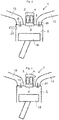
- the fluidic connection can, for example, be a channel arranged in the valve stem which, when the stem is deflected in the direction of the main combustion chamber, is closed by the partition and, when the stem is deflected in the direction of the antechamber, represents a fluid connection between the antechamber and the main combustion chamber.
- a T-shaped channel in the valve stem is to be thought of, so that with a corresponding deflection of the tappet, the channel is easily closed by engaging the tappet in the partition.
- valve is closed when the mixture in the prechamber has just ignited, which at the same time corresponds to the period in which the overpressure prevailing in the prechamber is highest compared to the pressure prevailing in the main combustion chamber.
- the wall separating the antechamber and the main combustion chamber and the valve stem are designed such that in an open and / or closed state a respective side of the wall is aligned flush with the valve.
- valve or a valve stem of the valve is arranged coaxially with an axis of symmetry of the main combustion chamber, preferably also arranged coaxially with an axis of symmetry of the prechamber and / or the prechamber housing.
- the fluidic connection formed in an open state of the valve through the Partition is symmetrical or rotationally symmetrical to an axis of symmetry of the main combustion chamber.
- the engine is operated with hydrogen or a fuel that contains hydrogen as a main component or as an admixture (e.g. Hythane) or that it is another fuel whose ignitability also for lambda values above 2.5, preferably above 3, and very particularly preferably above 5.
- a fuel that contains hydrogen e.g. Hythane
- the engine is provided with multi-stage charging of the air to be introduced into the main combustion chamber, with at least one charge air cooler preferably being arranged in a charge air path between the individual charging stages or at least one associated charge air cooler in the charge air path for each of the stages is arranged downstream.
- the invention can provide that with at least two series-connected compressor units of the multi-stage charging, a charge air cooler is connected immediately after each other, which cools the charge air that is compressed and raised in temperature by a compressor unit. It is preferably provided that the at least two charge air coolers, each downstream of a compressor unit, are integrated on the secondary side in mutually independent cooling circuits, at least one of which is not in fluid connection with a primary cooling circuit connected to the engine. In these two circuits, it can be provided that the two respective circulating pumps and heat exchangers, through which the thermal power carried away from the respective cooling circuit at the waste heat sources of the engine is dissipated to the ambient air, are separated from one another.
- the cooling circuit separated from the primary cooling circuit of the engine which is also referred to as the low-temperature circuit, has a circulating pump, which is preferably operated as required, and thus the separated cooling circuit can be operated with a definable variable cooling capacity.
- This circulating pump and / or a fan on the external heat exchanger via which the low-temperature cooling circuit dissipates thermal power to the environment, can be driven, for example, via a controlled or regulated electric machine, so that the low-temperature cooling circuit only has a very low flow temperature and a very high coolant mass flow provides if this is necessary or only takes place if a corresponding added value for the motor in an overall system consideration is drawn from this energy expenditure required for this.
- a water injection device for injecting water into the charge air path is provided for cooling the charge air, the water injected into the charge air path preferably being a condensate from the exhaust gas.
- water obtained from the exhaust gas can be used to cool charge air.
- a water injection device can be provided which injects water into the charge air path in order to cool the charge air.
- the single-stage or multi-stage charging can be varied in terms of its output, preferably by means of a controllable and / or regulatable compressor.
- a controllable and / or regulatable compressor for example, this can be implemented by an exhaust gas turbocharger with an individually controllable waste gate, a turbocharger with a variable turbine geometry, a charger driven by an electric drive, etc.
- Such a need-based charging prevents unnecessarily strong charging in the lower and middle load range of the engine and consequently saves energy.
- the fuel injector is designed to deliver a fuel, preferably hydrogen or a fuel with more than 70% molecular hydrogen, at a pressure in the range from 200 to 500 bar, preferably 200 to 400 bar, preferably 250 to 350 bar and very particularly preferably in the range from 290 to 310 bar.
- a pressure for injecting fuel through the fuel injector is 300 bar.
- the invention also relates to a method for controlling an engine described above, which is provided with an actively controllable valve in the partition wall of the prechamber and main combustion chamber, the valve being closed shortly before the end of the fuel supply taking place via the injector so that the fuel in the end is in The fuel supplied to the main combustion chamber flows completely through the overflow channels in order to ensure additional swirling of a mixture in the main combustion chamber.
- This additional turbulence ensures particularly good mixing of the mixture in the antechamber and accordingly ensures a uniform and at the same time optimal spray pattern for the ignition torches shooting out of the antechamber.
- valve is temporarily opened during a compression phase of the cylinder in order to achieve an increased increase in the combustion air ratio lambda in the prechamber, provided this is functionally advantageous or also to enable the use of such fuel whose ignitability does this requires.
- the invention also relates to an on-road or off-road vehicle, in particular a mobile work machine with a motor according to one of the variants presented above.
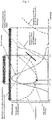
- Fig. 1 shows different effects of changes in the combustion air ratio lambda for the fuels natural gas and hydrogen.
- the significantly increased amount of charge air which is preferably cooled in order to achieve at least partial compensation for the heating caused by the compression, ensures an effective reduction in the combustion chamber temperature, which brings about a desirable decrease in NOx emissions and an increase in knock resistance.
- the knock resistance can be increased by a very late fuel injection, since the period in which an unwanted or. uncontrolled local ignition could occur, is extremely shortened.
- the activation energy required to trigger the ignition in the combustion chamber is brought in from the outside; mostly with a spark plug. This means that initially only a comparatively small amount of activation energy is available, which is why a comparatively high ignitability of the mixture is essential. Furthermore, a sufficiently high burning rate is essential in order to be able to achieve higher engine speeds.
- the volume of the main combustion chamber exceeds the internal volume of its associated antechamber by orders of magnitude. Therefore, the energy content of an ignition spark of an ordinary spark plug represents an adequate proportion of the activation energy for igniting the entire mixture in the prechamber.
- the mixture ignited in the prechamber which in turn releases a multiple of the energy of a spark plug spark, shoots through the overflow channels into the main combustion chamber, where it ensures multiple ignition at different locations and within a short period of time.
- An unflushed antechamber receives its mixture in the course of compression during the compression phase of the cylinder. Apart from a small residual amount of compressed exhaust gas, the composition of the mixture in the antechamber results from the processes in the main combustion chamber. The fuel supply into the main combustion chamber must take place in good time before the ignition spark is triggered, so that an adequate supply of the antechamber is ensured in the course of the compression.
- a flushed antechamber has its own fuel supply.
- the air supply into the antechamber is carried out in the same way via the compression taking place in the main combustion chamber.
- the air or oxygen supply for the antechamber is therefore carried out via the mixture from the main combustion chamber.
- a purged prechamber can be operated with an almost constant combustion air ratio regardless of the current operating point of the engine, which is particularly advantageous for igniting the mixture there in the prechamber.
- the main combustion chamber which is preferably set to lean operation so that the aforementioned advantages of a high degree of efficiency and low raw emissions come into full effect there.
- Only the approximately 1% energy conversion (of the total energy of the combustion process of a cylinder) in the prechamber to provide the ignition energy for the mixture may take place with poor efficiencies and possibly increased raw emissions.
- Fig. 2 now shows a schematic representation of an engine 1 with an associated main combustion chamber 2.
- a displaceably mounted piston 16 is arranged therein, which can strongly compress the mixture present in the main combustion chamber 2.
- the arrangement 1 has an air inlet 17 and an air outlet 18, which can be closed by means of corresponding valves 19, 20. With a corresponding position of the at least one inlet valve 19, fresh air is introduced into the main combustion chamber 2 via this and the vast majority of the combustion exhaust gas is discharged from the main combustion chamber 2 via the at least one outlet valve 20 after combustion.
- the antechamber 3 which is separated by a partition 8 provided with passages.
- An ignition device 4, for example a spark plug, and an injector 5 are located in this prechamber 3 is referred to as the active antechamber.
- the fuel for the mixture to be ignited in the main combustion chamber 2 is introduced via an injector 21 arranged in the main combustion chamber.
- Fig. 3 shows an embodiment of the invention, which is characterized by the presence of only one injector 5, which is arranged in the prechamber 3 or protrudes into it and therefore the fuel is injected into the prechamber 3.
- the fuel required for the main combustion chamber is also output from the injector 5 protruding into the prechamber 3, so that the fuel first has to flow from the prechamber 3 into the main combustion chamber 2.
- the prechamber 3 can be arranged in a position which is advantageous for the fuel to flow into the main combustion chamber 2 and for shooting the ignition torches into the main combustion chamber 2.
- the required number of components is significantly reduced, since there is now one less injector and, of course, the associated supply line and control are also omitted.
- Fig. 4 shows an advantageous embodiment of the invention in which the antechamber 3 is arranged in the axis of symmetry S of the main combustion chamber 2, so that when fuel flows out of the antechamber 3 into the main combustion chamber 2, fuel is particularly evenly distributed in the main combustion chamber 3 .
- This arrangement position of the antechamber 3 is of particular advantage since the ignition torches that shoot out of the overflow channels can lead to a uniform ignition of the mixture in the main combustion chamber 2.
- Fig. 5 shows an enlarged view of the antechamber 3 in which one can now also clearly see the overflow channels 6 (sometimes also called firing channels) which connect the antechamber 3 to the main combustion chamber 2 through the partition 8.
- the outlet end of an injector 5 protrudes into the interior of the prechamber 3 and not only provides the fuel for the ignition of the prechamber 3, but also a highly precisely metered amount of fuel for the combustion process in the main combustion chamber 2.
- a spark plug 4 is also provided there, the spark gap of which is formed in the prechamber 3, which, for example, can ignite the mixture in the prechamber 3 by means of a targeted sparkover.
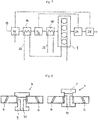
- Fig. 6 shows the time course of the prechamber internal pressure and the combustion air ratio lambda of the prechamber mixture for two processes with different injection times.
- the fuel injection must be completed before the end of the compression stroke of the cylinder, because the prechamber 3 has to be supplied with a certain amount of the mixture in the main combustion chamber 2 so that the oxygen required for prechamber ignition is available.
- this conditioning results solely from the repercussions of (i) the mixture state (lambda, pressure, temperature, etc.) in the main combustion chamber 2 at the end of the fuel injection and (ii) the change in the mixture state in the main combustion chamber 2 due to the ongoing Compression, which leads to the overflow of a certain proportion of the mixture from the main combustion chamber 2 into the antechamber 3. Due to the extremely small proportion of the mixture displaced from the main combustion chamber 2 into the antechamber 3, this is of no significance for the mixture located in the main combustion chamber 2.
- the combustion air ratio lambda at the ignition point has a value of approx. 0.53.
- the time periods within which these processes take place can, however, be so short that the combustion air ratio lambda is not homogeneous even in a small volume such as an antechamber 3.
- the basic concept of the invention is therefore particularly suitable for a hydrogen engine. Because a hydrogen-air mixture is already ignitable with a very low proportion of air (down to a minimum lambda of 0.15), whereas this design example also does Lambda values less than 0.7 would be unsuitable for a gas engine operated with natural gas (methane).
- the curves shown relate to a hydrogen engine at the operating point of its maximum output power of 450 kW at a speed of 1900 min -1 and thus to a constellation which is very demanding for the system according to the invention.
- the maximum amount of fuel must be supplied from the injector 5, which injects into the prechamber 3, via the overflow ducts 6 into the main combustion chamber 2.
- This process must be completed in good time so that a sufficiently high amount of mixture is still displaced from the main combustion chamber 2 into the antechamber 3.
- a sufficiently high burning speed must occur in the main combustion chamber to cover the high speed.
- the injection rate is approx. 11.5 g / s, the injection duration approx. 7.63 ms (and the amount of hydrogen consumed within such a work cycle approx. 0.088 g).
- the pre-chamber charge is conditioned with the start of injection of the last partial injection predetermined because the end of this injection process has already been determined by the amount of fuel to be supplied to the main combustion chamber 3.
- a corresponding sensor system using hardware and / or software is advantageous or necessary.
- Said actuators and sensors are then part of one or more controls and / or regulators.
- At least some of these controls and / or regulations are preferably software, which in turn is implemented on a computing unit.
- This software then contains the virtual sensors required, for example, in the form of arithmetic models and / or state estimators as well as characteristic maps, controllers, parameters, etc.
- the engine control device takes over the function of this arithmetic unit.
- this processing unit can also be distributed over physically different control units.
- crankshaft sensor crankshaft sensor
- camshaft sensor camshaft sensor
- rail pressure the output value of a height pressure cell
- temperatures air gap at the exit of the intercooler, exhaust gas collector oil, cooling water, etc.
- crankshaft phase angle Possible calculation variables, which in turn serve as input variables for certain sub-models, are: crankshaft phase angle, engine speed, target fuel injection quantity, internal combustion chamber pressure, etc.
- the application of the system according to the invention is primarily for the internal combustion engine use of hydrogen or such a use of fuel mixtures which contain a high proportion of hydrogen and others Fuels whose ignitability has a correspondingly large bandwidth over the lambda combustion air ratio are very promising.
- the aim is to use the system according to the invention in an engine 1 which preferably operates in extremely lean operation.
- the engine 1 is operated with hydrogen or a fuel that contains hydrogen as the main component or as an admixture, or it is a hydrogen-like fuel, or it is another fuel that has an ignitability for lambda above 2.5 and particularly preferably has an ignitability for lambda equal to or above 3 and very particularly preferably has an ignitability for lambda equal to or above 5.
- the high excess of air causes a correspondingly strong increase in the knock limit, which is used to increase the compression ratio in order to achieve an increase in efficiency.
- the knock limit which limits the compression ratio, but also the load-bearing capacity of the antechamber.
- the compression ratio is preferably between 11 and 20, particularly preferably between 11 and 17 and very particularly preferably between 12 and 15.
- FIG Fig. 7 An embodiment of a concept known as such is shown in FIG Fig. 7 . It is a two-stage supercharging 11, 12 with two-stage cooling 14, 15 in which the charge air compressed in the first compressor 11 is first passed through a charge air cooler 14 and then compressed again in a second compressor 12 and cooled again in the downstream charge air cooler 15 will. Between the two compressors 11, 12 arranged in series in the charge air path 13, there is provided a charge air cooler 14, which is referred to as a charge air intercooler. Very particularly preferably, at least one so-called charge air intercooler 14 is located between two compressors 11, 12 arranged in series along the air charge path 13. This is a cooling circuit that is separated from the primary cooling circuit 22 of the engine 1.
- the primary cooling circuit is also referred to as the high-temperature cooling circuit 22.
- the two cooling circuits 22, 23 are the two respective circulating pumps and heat exchangers through which the from the respective cooling circuit 22, 23 are connected the thermal power removed from the waste heat sources of the engine 1 is dissipated to the ambient air, separated from one another.
- the operation of the low-temperature cooling circuit 23 requires a comparatively high output, which is why a needs-based operation of its circulating pump and / or the fan, which supports the dissipation of heat to the ambient air, is preferred.
- a two-stage charge air cooler 15 instead of a single-stage charge air cooler 15, a two-stage charge air cooler 15 'could be used, the secondary side of a first stage preferably being connected to the high-temperature cooling circuit 22 and the secondary side of the second stage being preferably connected to the low-temperature cooling circuit 23.
- a certain amount of water can be injected into the charge air path 13 as additional cooling.
- the water can be extracted from the exhaust gas as condensate.
- At least one controllable or regulatable compressor is preferably used to compress the charge air;
- an exhaust gas turbocharger with an individually controllable waste gate and / or a turbocharger with a variable turbine geometry (a so-called VTG charger) and / or a charger, etc. driven by an electric motor and / or mechanically by a power take-off of the engine are used.
- the low emissions of nitrogen oxides due to the strong emaciation are fully effective in the embodiment according to the invention as a hydrogen engine. There is therefore great potential in the hydrogen engine according to the invention Simplification of your exhaust aftertreatment or even the possibility of being able to do without exhaust aftertreatment completely. If the running distances of certain filters or catalytic converters can be reduced or even omitted, this offers a significant potential for lowering the exhaust back pressure, which in turn results in fuel savings.
- valve 7 in an area of the antechamber wall 8 which adjoins the main combustion chamber 2 or protrudes into it is.
- the additional flow cross-section between the antechamber 3 and the combustion chamber 2 is preferably approximately the same size as the total flow cross-section of the overflow channels 6.
- the fluid connection that is additionally available when the valve 7 is open should be roughly dimensioned be that approximately half of the gas flow (depending on the period in the working cycle: a) fuel or b) mixture) flows through the opening cross-section of the valve 7. It is advantageous if, when the fuel flows from the prechamber 3 into the main combustion chamber 2, a significant proportion takes place via the overflow ducts 6, because the overflow ducts 6 are already designed to serve as a firing duct in such a way that even when fuel flows through to charge the main combustion chamber 2 one effective turbulence is present. The same requirement also applies when the mixture flows into the antechamber 3.
- the closing element of the valve 7 can be preloaded accordingly by a suitable spring element so that when the mixture in the prechamber 3 has just ignited, which at the same time corresponds to the period in which the overpressure prevailing in the prechamber 3 compared to the pressure present in the main combustion chamber 2 is highest, is closed. Therefore, this additional flow cross-section is not available to the ignition torches, but they can only spread over the overflow channels, which therefore affect their function as to serve so-called firing channels, can be optimized. Thus, these can have a sufficiently small total flow cross section, an advantageous division into a favorable number of individual overflow channels 6, an optimal arrangement adapted to this in the antechamber wall and an adapted contour shape.
- valve 7 When using such a valve 7 in a 2-stroke engine, the same relationships exist with regard to preferred valve positions depending on the material flows (fuel, mixture and ignited prechamber mixture) between the prechamber and the main combustion chamber as in a 4-stroke engine.
- valve 7 Regardless of the design of the motor 1, such a valve 7 would preferably be used, which can be opened and closed in a controllable manner.
- valve 7 would close (shortly) before the end of the charging of the main combustion chamber 2, so that the amount of fuel fed into the main combustion chamber 2 at the end is passed completely through the overflow channels 6 and therefore provides additional turbulence for the advantage of a better mixture formation in the Main combustion chamber 2.
- the valve 7 is temporarily opened during the operating phase in which the air is fed to the prechamber 3 by the inflow of mixture from the main combustion chamber 2. Particularly preferably, the valve 7 is then closed (shortly) before the end of the charging process, so that the mixture that has finally pushed into the antechamber 2 is passed completely through the overflow channels 6 and therefore provides additional turbulence to the advantage of a better mixture formation in the prechamber 3 which results from the fuel in the prechamber 3 and from the mixture flowing in from the main combustion chamber 2.
- the additionally available flow cross-section creates a corridor (i) for lowering the fuel injection pressure, (ii) the possibility of a later fuel injection with the advantages already explained and (iii) a simplification to provide higher oxygen proportions in the prechamber 3, ie to achieve the increase in the combustion air ratio lambda; at least an approximation to the value 1, so that the invention can also be applied to engines 1 operated with natural gas.
- the latter is useful in order, on the one hand, to be able to feed the highest possible amount of fuel into the small internal volume of the prechamber 3 and to use this in its function as an ignition amplifier. Furthermore, in this way the prechamber 3 can be operated in such a way that the combustion of the mixture there takes place as close as possible to the maximum possible temperature, which is particularly advantageous for a hydrogen engine.
- exhaust gas aftertreatment is sought with the hydrogen without an SCR system, it can of course be more productive to set the combustion air ratio lambda to a value that brings about an optimum between the two opposing requirements of a high temperature and the lowest possible raw NOx emissions.
- the supply of fuel flows into the main combustion chamber in a manner comparable to that of direct injection under high pressure and with an advantageous spray pattern, and that all openings through which the fuel jets penetrate into the main combustion chamber are particularly advantageously positioned as is the case with direct injection, but at the same time, secondly, the firing torches can also be fired into the main combustion chamber 2 starting from the optimal position, which is only possible with a device according to the invention.
- a further increase in the combustion air ratio lambda can possibly be decisive for achieving at least one further discrete step to reduce the exhaust gas aftertreatment, e.g. switching to a smaller size or the omission of an entire stage, e.g. the omission of the SCR system up to a complete one Saving an AGN system.
- the task of the prechamber of a prechamber diesel engine is fuel atomization.
- An engine according to the invention receives the fuel that has already been atomized due to the high-pressure injection.
- the primary function of the prechamber of an engine according to the invention is that of an ignition amplifier. Therefore, the volumes of the prechamber and the main combustion chamber in an engine according to the invention differ by orders of magnitude that can exceed powers of ten, whereas this is only a factor of the order of magnitude of 3 in a prechamber diesel engine.
Landscapes
- Engineering & Computer Science (AREA)
- Chemical & Material Sciences (AREA)
- Combustion & Propulsion (AREA)
- Mechanical Engineering (AREA)
- General Engineering & Computer Science (AREA)
- Chemical Kinetics & Catalysis (AREA)
- General Chemical & Material Sciences (AREA)
- Oil, Petroleum & Natural Gas (AREA)
- Combustion Methods Of Internal-Combustion Engines (AREA)
Applications Claiming Priority (2)
| Application Number | Priority Date | Filing Date | Title |
|---|---|---|---|
| CH00481/20A CH717344A1 (de) | 2020-04-23 | 2020-04-23 | Motor mit Vorkammerzündung und Verfahren zum Steuern eines solchen Motors. |
| CH00073/21A CH717353A2 (de) | 2020-04-23 | 2021-01-26 | Motor mit Vorkammerzündung und Verfahren zum Steuern eines solchen Motors. |
Publications (4)
| Publication Number | Publication Date |
|---|---|
| EP3901435A2 true EP3901435A2 (fr) | 2021-10-27 |
| EP3901435A3 EP3901435A3 (fr) | 2021-11-24 |
| EP3901435B1 EP3901435B1 (fr) | 2026-01-07 |
| EP3901435C0 EP3901435C0 (fr) | 2026-01-07 |
Family
ID=75639818
Family Applications (1)
| Application Number | Title | Priority Date | Filing Date |
|---|---|---|---|
| EP21169918.6A Active EP3901435B1 (fr) | 2020-04-23 | 2021-04-22 | Véhicule avec moteur à gaz d'allumage à préchambre et procédé de commande d'un tel moteur à gaz |
Country Status (2)
| Country | Link |
|---|---|
| US (4) | US11300038B2 (fr) |
| EP (1) | EP3901435B1 (fr) |
Cited By (1)
| Publication number | Priority date | Publication date | Assignee | Title |
|---|---|---|---|---|
| EP3981978A1 (fr) | 2020-10-09 | 2022-04-13 | MAHLE Powertrain, LLC | Procédé de fonctionnement d'un moteur à combustion alimenté en hydrogène |
Families Citing this family (8)
| Publication number | Priority date | Publication date | Assignee | Title |
|---|---|---|---|---|
| DE102021121214B4 (de) * | 2021-08-16 | 2024-12-12 | Keyou GmbH | Verfahren zum Betrieb einer fremdzündenden Verbrennungskraftmaschine und Steuereinrichtung zur Durchführung des Verfahrens |
| US12565849B2 (en) | 2022-10-27 | 2026-03-03 | Saudi Arabian Oil Company | Spray guided stratification for fueling a passive pre-chamber |
| US11959435B1 (en) | 2022-10-27 | 2024-04-16 | Saudi Arabian Oil Company | Turbulent jet controlled compression ignition (TJCCI) engine |
| JP2025018643A (ja) * | 2023-07-27 | 2025-02-06 | ヤンマーホールディングス株式会社 | エンジン装置及びエンジン装置の制御方法 |
| JP2025018642A (ja) * | 2023-07-27 | 2025-02-06 | ヤンマーホールディングス株式会社 | エンジン装置 |
| US12168952B1 (en) * | 2023-08-16 | 2024-12-17 | Caterpillar Inc. | Prechamber ignited engine and operating methods therefor |
| US12410760B2 (en) | 2023-11-29 | 2025-09-09 | Cummins Power Generation Inc. | Control system for an internal combustion engine, internal combustion engine system, and method for controlling internal combustion engine |
| CN119712341B (zh) * | 2024-12-18 | 2025-10-14 | 中国船舶集团有限公司第七一一研究所 | 点火结构、发动机、点火方法以及燃料供给方法 |
Family Cites Families (21)
| Publication number | Priority date | Publication date | Assignee | Title |
|---|---|---|---|---|
| IT1027484B (it) * | 1974-02-21 | 1978-11-20 | Renault | Motore a combustione interna a carica strativicata, ultizzante due combustibili |
| US4441476A (en) * | 1982-11-04 | 1984-04-10 | Roberts James E | Charge air cooling system |
| JP2814346B2 (ja) * | 1994-03-28 | 1998-10-22 | 株式会社いすゞセラミックス研究所 | ディーゼルエンジンの燃焼室構造 |
| JP2001082148A (ja) | 1999-09-14 | 2001-03-27 | Osaka Gas Co Ltd | エンジン及びその運転方法 |
| JP4368028B2 (ja) | 2000-03-22 | 2009-11-18 | 大阪瓦斯株式会社 | トーチ点火式エンジン |
| KR20030004373A (ko) * | 2000-04-28 | 2003-01-14 | 이와타니 산교 가부시키가이샤 | 압축 점화 엔진용 액화 가스 연료 |
| DE10217996A1 (de) * | 2002-04-23 | 2003-11-13 | Man B & W Diesel Ag | Selbstzündende gemischverdichtende Brennkraftmaschine und Verfahren zu ihrem Betrieb |
| JP2006322367A (ja) | 2005-05-18 | 2006-11-30 | Nissan Motor Co Ltd | 副室式内燃機関 |
| CA2626995C (fr) * | 2008-04-30 | 2009-12-01 | Westport Power Inc. | Methode de commande d'injection de carburant pour moteur a combustion interne par carburant gazeux a injection directe |
| US9574490B2 (en) * | 2013-07-23 | 2017-02-21 | Cummins Inc. | Interstage gas injection for multi-stage turbocharged natural gas engine |
| CN104863712A (zh) * | 2014-02-21 | 2015-08-26 | 卡特彼勒发动机有限责任两合公司 | 运行气体燃料的内燃发动机中的失火检测 |
| WO2015138987A1 (fr) | 2014-03-14 | 2015-09-17 | Advanced Green Technologies, Llc | Injecteur-allumeur à préchambre pour combustion de carburant gazeux, et systèmes et méthodes associés |
| EP2957750A1 (fr) * | 2014-06-16 | 2015-12-23 | Caterpillar Motoren GmbH & Co. KG | Procédé pour contrôler un moteur à combustion interne |
| US9556809B2 (en) * | 2014-12-12 | 2017-01-31 | General Electric Company | System and method for optimal fueling of an engine |
| US9890689B2 (en) * | 2015-10-29 | 2018-02-13 | Woodward, Inc. | Gaseous fuel combustion |
| US20160341105A1 (en) * | 2016-08-08 | 2016-11-24 | Caterpillar Inc. | System for scavenging pre-combustion chamber |
| AT519257B1 (de) | 2016-11-04 | 2018-05-15 | Avl List Gmbh | Brennkraftmaschine |
| US10116122B2 (en) | 2016-12-09 | 2018-10-30 | Vianney Rabhi | Spark plug with shuttle electrode |
| US11002177B2 (en) * | 2018-11-15 | 2021-05-11 | Caterpillar Inc. | System and method for staged pre-chamber purging |
| JP2019044780A (ja) * | 2018-12-20 | 2019-03-22 | 株式会社三井E&Sマシナリー | 船舶の機関運転方式 |
| DE102019128334A1 (de) * | 2019-10-21 | 2021-04-22 | Volkswagen Aktiengesellschaft | Spülfluid-Versorgung einer aktiven Vorkammer eines aufgeladenen Ottomotors in Kombination mit einer Turbokühlung |
-
2021
- 2021-04-20 US US17/234,893 patent/US11300038B2/en active Active
- 2021-04-22 EP EP21169918.6A patent/EP3901435B1/fr active Active
-
2022
- 2022-03-04 US US17/686,839 patent/US11698021B2/en active Active
-
2023
- 2023-05-23 US US18/200,697 patent/US12092015B2/en active Active
- 2023-12-20 US US18/390,561 patent/US12188399B2/en active Active
Cited By (1)
| Publication number | Priority date | Publication date | Assignee | Title |
|---|---|---|---|---|
| EP3981978A1 (fr) | 2020-10-09 | 2022-04-13 | MAHLE Powertrain, LLC | Procédé de fonctionnement d'un moteur à combustion alimenté en hydrogène |
Also Published As
| Publication number | Publication date |
|---|---|
| US20220251998A1 (en) | 2022-08-11 |
| US20230366343A1 (en) | 2023-11-16 |
| US20210332743A1 (en) | 2021-10-28 |
| EP3901435A3 (fr) | 2021-11-24 |
| US11300038B2 (en) | 2022-04-12 |
| EP3901435B1 (fr) | 2026-01-07 |
| US11698021B2 (en) | 2023-07-11 |
| US12188399B2 (en) | 2025-01-07 |
| US12092015B2 (en) | 2024-09-17 |
| US20240200488A1 (en) | 2024-06-20 |
| EP3901435C0 (fr) | 2026-01-07 |
Similar Documents
| Publication | Publication Date | Title |
|---|---|---|
| EP3901435B1 (fr) | Véhicule avec moteur à gaz d'allumage à préchambre et procédé de commande d'un tel moteur à gaz | |
| DE69809492T2 (de) | Brennkraftmaschine | |
| DE10009180C2 (de) | Verfahren zur Erzeugung eines homogenen Gemischs für selbstzündende Brennkraftmaschinen und zur Steuerung des Verbrennungsprozesses | |
| DE102015200048B4 (de) | Verfahren zum Betreiben einer Brennkraftmaschine | |
| DE69300473T2 (de) | Brennkraftmaschine. | |
| DE102014201215B4 (de) | Aufgeladene Brennkraftmaschine mit Teilabschaltungund Verfahren zum Betreiben einer derartigen Brennkraftmaschine | |
| DE102016200237A1 (de) | Direkteinspritzende aufgeladene Brennkraftmaschine mit Wassereinspritzung und Verfahren zum Betreiben einer derartigen Brennkraftmaschine | |
| EP1039112A2 (fr) | Système d'alimentation de combustible pour un moteur à combustion interne à allumage commandé | |
| DE102015214616B4 (de) | Verfahren zum Betreiben einer abgasturboaufgeladenen Brennkraftmaschine mit Teilabschaltung | |
| EP2992195B1 (fr) | Moteur à combustion interne à piston alternatif ainsi que procédé pour faire fonctionner un moteur à combustion interne à piston alternatif | |
| DE102017120512B4 (de) | Verfahren zum Betreiben eines Wasserstoffmotors für ein Kraftfahrzeug | |
| EP2801714A1 (fr) | Moteur à combustion interne doté de cylindre débrayable et procédé de fonctionnement d'un tel moteur à combustion interne | |
| EP0527362B1 (fr) | Procédé et dispositif pour diminuer les oxides azotiques expulsés par des moteurs à combustion interne | |
| DE10321794A1 (de) | Verfahren zum Betreiben einer Brennkraftmaschine | |
| CH717353A2 (de) | Motor mit Vorkammerzündung und Verfahren zum Steuern eines solchen Motors. | |
| DE602004011319T2 (de) | Motorventilbetätigung zur verbrennungsverbesserung | |
| DE19932119C2 (de) | Fremdgezündete Hubkolbenbrennkraftmaschine | |
| DE2602127C2 (de) | Fremdgezündete Brennkraftmaschine | |
| DE102013209305A1 (de) | Optimierung von Motorsteuerungen bei Kraftstoffnachverbrennung | |
| WO2023066828A1 (fr) | Moteur à combustion interne et procédé d'opération d'un moteur à combustion interne | |
| DE4134404A1 (de) | Verfahren zur umwandlung von waermeenergie in mechanische bewegungsenergie sowie vorrichtung zum druchfuehren dieses verfahrens | |
| EP4045784A1 (fr) | Procédé de fonctionnement d'un moteur à combustion interne | |
| EP4253738B1 (fr) | Procédé de fonctionnement d'un moteur à pistons à entraînement par cycles | |
| DE102015200047A1 (de) | Brennkraftmaschine mit Teilabschaltung und Verfahren zum Betreiben einer derartigen Brennkraftmaschine | |
| DE2548086A1 (de) | Brennkraftmaschine mit paarweise etwa phasengleich arbeitenden arbeitsraeumen |
Legal Events
| Date | Code | Title | Description |
|---|---|---|---|
| PUAI | Public reference made under article 153(3) epc to a published international application that has entered the european phase |
Free format text: ORIGINAL CODE: 0009012 |
|
| STAA | Information on the status of an ep patent application or granted ep patent |
Free format text: STATUS: THE APPLICATION HAS BEEN PUBLISHED |
|
| PUAL | Search report despatched |
Free format text: ORIGINAL CODE: 0009013 |
|
| AK | Designated contracting states |
Kind code of ref document: A2 Designated state(s): AL AT BE BG CH CY CZ DE DK EE ES FI FR GB GR HR HU IE IS IT LI LT LU LV MC MK MT NL NO PL PT RO RS SE SI SK SM TR |
|
| AK | Designated contracting states |
Kind code of ref document: A3 Designated state(s): AL AT BE BG CH CY CZ DE DK EE ES FI FR GB GR HR HU IE IS IT LI LT LU LV MC MK MT NL NO PL PT RO RS SE SI SK SM TR |
|
| RIC1 | Information provided on ipc code assigned before grant |
Ipc: F02B 19/02 20060101ALI20211018BHEP Ipc: F02M 21/02 20060101ALI20211018BHEP Ipc: F02B 19/12 20060101ALI20211018BHEP Ipc: F02B 19/10 20060101AFI20211018BHEP |
|
| STAA | Information on the status of an ep patent application or granted ep patent |
Free format text: STATUS: REQUEST FOR EXAMINATION WAS MADE |
|
| 17P | Request for examination filed |
Effective date: 20220517 |
|
| STAA | Information on the status of an ep patent application or granted ep patent |
Free format text: STATUS: EXAMINATION IS IN PROGRESS |
|
| 17Q | First examination report despatched |
Effective date: 20230929 |
|
| GRAP | Despatch of communication of intention to grant a patent |
Free format text: ORIGINAL CODE: EPIDOSNIGR1 |
|
| STAA | Information on the status of an ep patent application or granted ep patent |
Free format text: STATUS: GRANT OF PATENT IS INTENDED |
|
| INTG | Intention to grant announced |
Effective date: 20250929 |
|
| GRAS | Grant fee paid |
Free format text: ORIGINAL CODE: EPIDOSNIGR3 |
|
| GRAA | (expected) grant |
Free format text: ORIGINAL CODE: 0009210 |
|
| STAA | Information on the status of an ep patent application or granted ep patent |
Free format text: STATUS: THE PATENT HAS BEEN GRANTED |
|
| AK | Designated contracting states |
Kind code of ref document: B1 Designated state(s): AL AT BE BG CH CY CZ DE DK EE ES FI FR GB GR HR HU IE IS IT LI LT LU LV MC MK MT NL NO PL PT RO RS SE SI SK SM TR |
|
| REG | Reference to a national code |
Ref country code: CH Ref legal event code: F10 Free format text: ST27 STATUS EVENT CODE: U-0-0-F10-F00 (AS PROVIDED BY THE NATIONAL OFFICE) Effective date: 20260107 Ref country code: GB Ref legal event code: FG4D Free format text: NOT ENGLISH |
|
| REG | Reference to a national code |
Ref country code: IE Ref legal event code: FG4D Free format text: LANGUAGE OF EP DOCUMENT: GERMAN |
|
| U01 | Request for unitary effect filed |
Effective date: 20260107 |
|
| U07 | Unitary effect registered |
Designated state(s): AT BE BG DE DK EE FI FR IT LT LU LV MT NL PT RO SE SI Effective date: 20260113 |
|
| REG | Reference to a national code |
Ref country code: ES Ref legal event code: FG2A Ref document number: 3059252 Country of ref document: ES Kind code of ref document: T3 Effective date: 20260319 |