EP3900868A1 - Joining method - Google Patents
Joining method Download PDFInfo
- Publication number
- EP3900868A1 EP3900868A1 EP19898076.5A EP19898076A EP3900868A1 EP 3900868 A1 EP3900868 A1 EP 3900868A1 EP 19898076 A EP19898076 A EP 19898076A EP 3900868 A1 EP3900868 A1 EP 3900868A1
- Authority
- EP
- European Patent Office
- Prior art keywords
- metal member
- rotary tool
- angle
- joining
- face
- Prior art date
- Legal status (The legal status is an assumption and is not a legal conclusion. Google has not performed a legal analysis and makes no representation as to the accuracy of the status listed.)
- Granted
Links
Images






Classifications
-
- B—PERFORMING OPERATIONS; TRANSPORTING
- B23—MACHINE TOOLS; METAL-WORKING NOT OTHERWISE PROVIDED FOR
- B23K—SOLDERING OR UNSOLDERING; WELDING; CLADDING OR PLATING BY SOLDERING OR WELDING; CUTTING BY APPLYING HEAT LOCALLY, e.g. FLAME CUTTING; WORKING BY LASER BEAM
- B23K20/00—Non-electric welding by applying impact or other pressure, with or without the application of heat, e.g. cladding or plating
- B23K20/12—Non-electric welding by applying impact or other pressure, with or without the application of heat, e.g. cladding or plating the heat being generated by friction; Friction welding
- B23K20/122—Non-electric welding by applying impact or other pressure, with or without the application of heat, e.g. cladding or plating the heat being generated by friction; Friction welding using a non-consumable tool, e.g. friction stir welding
-
- B—PERFORMING OPERATIONS; TRANSPORTING
- B23—MACHINE TOOLS; METAL-WORKING NOT OTHERWISE PROVIDED FOR
- B23K—SOLDERING OR UNSOLDERING; WELDING; CLADDING OR PLATING BY SOLDERING OR WELDING; CUTTING BY APPLYING HEAT LOCALLY, e.g. FLAME CUTTING; WORKING BY LASER BEAM
- B23K20/00—Non-electric welding by applying impact or other pressure, with or without the application of heat, e.g. cladding or plating
- B23K20/12—Non-electric welding by applying impact or other pressure, with or without the application of heat, e.g. cladding or plating the heat being generated by friction; Friction welding
- B23K20/1205—Non-electric welding by applying impact or other pressure, with or without the application of heat, e.g. cladding or plating the heat being generated by friction; Friction welding using translation movement
-
- B—PERFORMING OPERATIONS; TRANSPORTING
- B23—MACHINE TOOLS; METAL-WORKING NOT OTHERWISE PROVIDED FOR
- B23K—SOLDERING OR UNSOLDERING; WELDING; CLADDING OR PLATING BY SOLDERING OR WELDING; CUTTING BY APPLYING HEAT LOCALLY, e.g. FLAME CUTTING; WORKING BY LASER BEAM
- B23K20/00—Non-electric welding by applying impact or other pressure, with or without the application of heat, e.g. cladding or plating
- B23K20/12—Non-electric welding by applying impact or other pressure, with or without the application of heat, e.g. cladding or plating the heat being generated by friction; Friction welding
- B23K20/122—Non-electric welding by applying impact or other pressure, with or without the application of heat, e.g. cladding or plating the heat being generated by friction; Friction welding using a non-consumable tool, e.g. friction stir welding
- B23K20/1245—Non-electric welding by applying impact or other pressure, with or without the application of heat, e.g. cladding or plating the heat being generated by friction; Friction welding using a non-consumable tool, e.g. friction stir welding characterised by the apparatus
- B23K20/1255—Tools therefor, e.g. characterised by the shape of the probe
-
- B—PERFORMING OPERATIONS; TRANSPORTING
- B23—MACHINE TOOLS; METAL-WORKING NOT OTHERWISE PROVIDED FOR
- B23K—SOLDERING OR UNSOLDERING; WELDING; CLADDING OR PLATING BY SOLDERING OR WELDING; CUTTING BY APPLYING HEAT LOCALLY, e.g. FLAME CUTTING; WORKING BY LASER BEAM
- B23K2101/00—Articles made by soldering, welding or cutting
- B23K2101/18—Sheet panels
-
- B—PERFORMING OPERATIONS; TRANSPORTING
- B23—MACHINE TOOLS; METAL-WORKING NOT OTHERWISE PROVIDED FOR
- B23K—SOLDERING OR UNSOLDERING; WELDING; CLADDING OR PLATING BY SOLDERING OR WELDING; CUTTING BY APPLYING HEAT LOCALLY, e.g. FLAME CUTTING; WORKING BY LASER BEAM
- B23K2103/00—Materials to be soldered, welded or cut
- B23K2103/08—Non-ferrous metals or alloys
- B23K2103/10—Aluminium or alloys thereof
Definitions
- the present invention relates to a joining method.
- Patent Document 1 A technology to friction-stir-weld metal members that have different thicknesses with a rotary tool has been known.
- An invention described in Patent Document 1 is intended to perform friction-stir-welding on metal members that have different thicknesses by inserting a rotary tool vertically into a stepped butted portion of the metal members and moving the rotary tool along the stepped butted portion.
- Patent Document 1 JP2012-218001A
- the conventional joining technology cannot sufficiently hold down a plastically flowing material while the metal members are being joined, because there is a space between the rotary tool and one of the metal members. As a result, there is a problem with the conventional joining technology that there are a lot of burrs produced, which results in the joint strength being not high enough.
- the present invention is intended to provide a joining method with which the joint strength is increased with less burrs being produced.
- the present invention has an aspect of comprising a butting process of a butting process of butting an end face of a first metal member and an end face of a second metal member against each other to form a butted portion that is stepped with a second front face of the second metal member being lower than a first front face of the first metal member and a joining process of performing friction-stir-welding on the butted portion that is stepped with a rotary tool, wherein the rotary tool includes a base side pin and a tip side pin, a taper angle of the base side pin is larger than a taper angle of the tip side pin, and a pin step portion in a staircase shape is formed on an outer circumferential face of the base side pin, wherein in the joining process, a rotation direction and a translation method of the rotary tool are set to such directions that the second metal member is on an advancing side, a target angle by which a rotation axis of the rotary tool is inclined toward the second metal member is set to such an angle that a burr formed
- the rotary tool is inclined toward the second metal member and the front faces of the first and second metal members can be sufficiently held down with the outer circumferential face of the base side pin having a larger taper angle, which contributes to inhibiting burrs being produced and increasing the joint strength.
- the burr formed on the front face of the second metal member has a thickness less than 0, which means that an undercut portion is produced, then the joint strength lowers.
- the thickness of the burr exceeds 130 pm, there are many burrs produced and the joint strength lowers because of shortage of metal at the joint portion.
- the target angle is preferably set to such an angle that in a cross-sectional plane that includes a rotation axis of the rotary tool and is perpendicular to a translation direction in which the rotary tool moves, an intersection point e is positioned on or above the front face of the second metal member, where the intersection point e is a point to be a rotational object of an intersection point d with respect to the rotation axis, the inter section point d being an intersection point between the outer circumferential face of the base side pin and the front face of the first metal member.
- the target angle is preferably set to such an angle that an inequality of ⁇ 0.05 ⁇ + 0.16 ⁇ s ⁇ -0.05 ⁇ + 0.40 is met, where s is the thickness of the burr in mm and ⁇ is the target angle (°), when a thickness ratio of the first metal member to the second metal member is between 1.33 and 2.
- the joining method as described enables preventing an undercut portion being formed and the thickness of the burr becoming larger.
- the joining method of the present invention enables reducing burrs and increasing the joint strength.
- a joining rotary tool for the embodiment is described.
- the joining rotary tool is a tool to be used for friction-stir-welding.
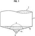
- a joining rotary tool F consists mainly of a base shaft portion F1, a base side pin F2 and a tip side pin F3.
- the base shaft pin F1 is in a columnar shape and secured to a main shaft of a friction stir welding apparatus.
- the base side pin F2 is formed to extend from the base shaft portion F1 and tapers to be thinner toward its tip.
- the base side pin F2 is in a conical shape with its tip portion cut off.
- the base side pin F2 has a taper angle A that may be appropriately formed to be, for example, between 135° and 160°. If the taper angle Ais smaller than 135° or larger than 160°, a surface roughness of the joined portion becomes large.
- the taper angle A is formed to be larger than a taper angle B of the tip side pin F3 to be described later.
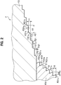
- a pin step portion F21 in a staircase shape is formed over a whole outer circumferential face of the base side pin F2 in its height direction.
- the pin step portion F21 is formed in a clockwise or counterclockwise spiral shape. That is, the pin step portion F21 is seen in a spiral shape in its plan view and in a staircase shape in its side view. Since the joining rotary tool F is rotated clockwise for this embodiment, the pin step portion F21 is formed in the clockwise shape from a base side to a tip side of the base side pin F2.
- the pin step portion F21 is preferably formed in the clockwise shape from a base side to a tip side of the base side pin F2. This enables reducing an amount of metal coming out of the metal members to be joined, because the plastically flowing material is directed toward the tip side of the base side pin F2 by the pin step portion F21.
- the pin step portion F21 is formed by a step bottom face F21a and a step side face F21b. A length X1 (horizontal direction length) between two apexes F21c, F21c next to each other of a pin step portions F21 is appropriately set based on a step angle C and a height Y1 of the step side face F21b, which are described later.
- the height Y1 of the step side face F21b may be appropriately set, for example, to between 0.1 and 0.4mm. If the height Y1 is smaller than 0.1mm, the joined portion has a relatively large surface roughness. On the other hand, if the height Y1 is larger than 0.4mm, the joined portion tends to have a relatively large surface roughness and the number of effective steps (number of steps of the pin step portion F21 being in contact with the metal member to be joined) becomes fewer.
- the step angle C made between the step bottom face F21a and the step side face F21b may appropriately set and, for example, to between 85° and 120°.
- the step bottom face F21a in this embodiment is in parallel with a horizontal plane.
- the step bottom face F21a may be inclined by between -5° and 15° relative to the horizontal plane from a rotation axis of the rotary tool toward its outer circumference (a minus angle corresponds to the step bottom face F21a extending outward inclining downward relative to the horizontal plane and a plus angle corresponds to the step bottom face F21a extending outward inclining upward relative to the horizontal plane).
- the length X1, the height Y1 of the step side face F21b, the step angle C and the angle of the step bottom face F21a relative to the horizontal plane are set in such a manner that the plastically flowing material flows out of the pin step portion F21 without being stuck on and adhering to the pin step portion F21 and is sufficiently held down by the step bottom face F21a for the joined portion to have a relatively small surface roughness.
- the tip side pin F3 is formed to extend continuously from the base side pin F2.
- the tip side pin F3 is in a conical shape with its tip portion cut off.
- the tip side pin F3 has a flat face that is formed on its tip portion.
- the tip side pin F3 has a taper angle B that is smaller than the taper angle A of the base side pin F2.
- a spiral groove F31 is engraved on an outer circumferential face of the tip side pin F3.
- the spiral groove F31 may be formed clockwise or counterclockwise.
- the spiral groove F31 may be engraved clockwise or counterclockwise from a base side to a tip side of the tip side pin F3 of the joining rotary tool F.
- the spiral groove F31 is engraved counterclockwise from a base side to a tip side of the tip side pin F3 of the joining rotary tool F.
- the spiral groove F31 is preferably formed clockwise from the base side to the tip side of the tip side pin F3. This enables reducing an amount of metal coming out of the metal members to be joined, because the plastically flowing material is directed toward the tip side of the tip side pin F3 by the spiral groove F31.
- the spiral groove F31 is formed by a spiral bottom face F31a and a spiral side face F31b.
- a length X2 denotes a length (horizontal direction length) between two apexes F31c, F31c next to each other of a pin step portion F31.
- a height Y2 denotes a height of the spiral side face F31b.
- a spiral angle D made between the spiral bottom face F31a and the spiral side face F31b may be set, for example, to between 45° and 90°.
- the spiral groove F31 is intended to have a function of contacting metal members to be joined to increase friction heat and direct the plastically flowing material toward the tip side.
- FIG.3 is a side elevation view of a first modification example of the rotary tool of the present invention.
- a joining rotary tool FA of the first modification example has the step angle C between the step bottom face F21a of the pin step portion F21 and the pin step side face F21b of the pin step portion F21, the step angle being equal to 85°.
- the step bottom face 21a is in parallel with the horizontal plane.
- the step angle C may be set to such an acute angle that the plastically flowing material is able to come out of the pin step portion F21 without being stuck on and adhering to the pin step portion F21 while friction-stirring is being performed, if the step bottom face F21a is in parallel with the horizontal plane.
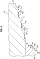
- Fig.4 is a side elevation view of a second modification example of the joining rotary tool of the present invention.
- a joining rotary tool FB of the second modification example has the step angle C of the pin step portion F21 being equal to 115°.
- the step bottom face F21a is in parallel with the horizontal plane.
- the step angle C may be set to an obtuse angle with the step bottom face F21a being in parallel with the horizontal plane as long as the pin step portion F21 functions as intended.
- Fig.5 is a side elevation view of a third modification example of the joining rotary tool of the present invention.
- a joining rotary tool FC has a step bottom face F21a extending from a rotation axis side toward an outer periphery inclining upward at 10° to the horizontal plane.
- the step side face F21b is in parallel with a vertical plane.
- the step bottom face F21a may be formed to incline upward relative to the horizontal plane from the rotation axis side toward an outer circumference as long as the plastically flowing material can be held down while friction-stirring is being performed. If any of the joining tools of the first to third modification examples above mentioned is used, an equivalent effect to that for the embodiments described below is obtained.
- the joining method of the embodiment includes a butting process and a joining process.
- a "front face” means an opposite face of a "back face”.
- the butting process is a process in which a first metal member 1 is butted against a second metal member 2, as shown in Fig.6 .
- the first metal member 1 and the second metal member 2 are made of a metal that can be friction-stirred such as aluminum, an aluminum alloy, copper, a copper alloy, titan, a titan alloy, magnesium, or a magnesium alloy.
- the first metal member 1 and the second metal member 2 used for this embodiment are made of an aluminum alloy.
- the first metal member 1 and the second metal member 2 used for this embodiment may be made different kinds of metals.
- the first metal member 1 has a larger thickness than the second metal member 2 does. Since a back face 1c of the first metal member 1 is flush with a back face 2c of the second metal member 2, there is a step at the butted portion J where end faces 1a, 2a are butted against each other.
- a thickness ratio between the first metal member 1 and the second metal member 2 may be appropriately set. For instance, if the thickness of the second metal member 2 is 1, the thickness of the first metal member 1 may be set to be between 1.2 and 2.5, preferably between 1.33 and 2.0. Alternatively, two metal members having an identical thickness may be butted against each other in the butting process in such a manner that there is a step between these metal members.
- the joining process is a process in which friction-stir-welding is performed on the butted portion J with the joining rotary tool F as shown in Fig.7 .
- the joining rotary tool F that is rotating clockwise is inserted into the butted portion J and made to move along the butted portion J.
- the first metal member 1 is on the right side of the translation direction of the joining rotary tool F that is rotating clockwise.
- the second metal member 2 is on the advancing side while the first metal member 1 is retreating side.
- the advancing side is a side where a relative speed of an outer circumference of the joining rotary tool F relative to a portion to be joined corresponds to a summation of a tangent speed of the outer circumference of the joining rotary tool F that is rotating and a translation speed of the joining rotary tool F.
- the retreating side corresponds to a side where the relative speed of the outer circumference of the joining rotary tool F relative to the portion to be joined becomes lower with the joining rotary tool F rotating in such a direction that the tangent speed of the circumference of the joining rotary tool F that is rotating is in the opposite direction to the translation direction of the joining rotary tool F.
- friction-stirring in the joining process is performed with a rotation axis U of the joining rotary tool F kept inclined by an inclination angle ⁇ (target angle) toward the second metal member 2 relative to the butted face (end faces 1a,2a).
- a plasticized zone W is formed along the translation track along which the joining rotary tool F has moved.
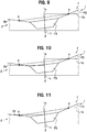
- Figs.9 to 11 show cross-sectional views of the joining process illustrating a target angle.
- a contact point at which the outer circumferential face of the base side pin F2 intersects with the front face 1b of the first metal member 1 in the cross-sectional view is referred to as an intersection point d and a point that is to be a rotational object of the intersection point d with respect to the rotation axis U is referred to as an intersection point e.
- the target angle may be set to such an angle that the intersection point e is positioned on the front face 2b of the second metal member 2 in the cross-sectional view.
- the target angle may be set to such an angle that the intersection point e is positioned above the front face 2b of the second metal member 2 in the cross-sectional view.
- the intersection point e is too far away from the front face 2b of the second metal member 2, the plastically flowing material cannot be held down sufficiently, and a burr formed on the front face 2b of the second metal member 2 becomes thick.
- the inclination angle (target angle) ⁇ may be appropriately set to such an angle that the thickness of the burr formed on the front face 2b of the second metal member 2 becomes between 0 and 130 pm after the joining process.
- the inclination angle (target angle) ⁇ is preferably set to such an angle that an inequality 1 of -0.05 ⁇ + 0.16 ⁇ s ⁇ -0.05 ⁇ + 0.40 is met, where s (mm) denotes a thickness of the burr formed on the front face 2b of the second metal member 2.
- the front face 1b of the first metal member 1 and the front face 2b of the second metal member 2 are held down by the outer circumferential face of the base side pin F2 whose taper angle is larger with the joining rotary tool F kept inclined toward the second metal member 2.
- the resultant burr can be made smaller, and the joint strength can be increased. If the thickness of the burr is smaller than 0, which corresponds to an undercut portion being formed, the joint strength decreases. Alternatively, if the thickness of the burr exceeds 130 pm, the joint portion is short of metal, which results in the joint strength becoming lower.
- the joining rotary tool F of the embodiment includes the base side pin F2 and the tip side pin F3 whose taper angle is smaller than the taper angle A of the base side pin F2.
- This structure makes it easier to insert the joining rotary tool F into the butted portion J.
- the taper angle B of the tip side pin F3 is smaller, the joining rotary tool F can be easily inserted to a deep position in the butted portion J.
- the taper angle B of the tip side pin F3 is smaller, the downward plastically flowing of friction-stirred material is reduced compared with the rotary tool 201. As a result, it is possible to prevent a kissing-bond from being formed under the plasticized zone W.
- the taper angle A of the base side pin F2 is larger, joining can be stably more performed than with the conventional rotary tool if the thickness of the metal member to be joined or the height at which joining is done varies.
- the plastically flowing material can be held down by the outer circumferential face of the base side pin F2, the uneven concave groove formed on the surface of the joined portion is made small and the raised portion that can be formed near the uneven concave groove is not formed or can be made smaller.
- the pin step portion F21 is shallow and has a wide exit, the plastically flowing material can easily move out of the pin step portion F21 while the plastically flowing material is being held down by the step bottom face F21a. Therefore, the plastically flowing material cannot easily get stuck on and adhere to the outer circumferential face of the base side pin F2. As a result, it is possible to inhibit a burr being formed, make the surface roughness of joined portion smaller and stabilize the joining quality.
- TEST 1 is intended to examine a relation between the thickness of the burr and a fatigue strength
- TEST 2 is intended to examine a relation between the thickness of the burr and the inclination angle (target angle) ⁇ of the joining rotary tool F.
- the fatigue strength of each of these members is 120 MPa.
- the inclination angles (target angle) ⁇ that were tested were an inclination angle ⁇ 1 for the test piece P1, an inclination angle ⁇ 2 for the test piece P2, an inclination angle ⁇ 3 for the test piece P3, an inclination angle ⁇ 4 for the test piece P4 and an inclination angle ⁇ 5 for the test piece P5.
- These inclination angles vary according to a relation of ⁇ 1 > ⁇ 2 > ⁇ 3 > ⁇ 4 > ⁇ 5 .
- the test piece P1 was prepared through the joining process with the intersection point e kept below the front face 2b of the second metal member 2 as shown in Fig.11 .
- An undercut portion K was formed on the front face 2b of the second metal member 2 of the test piece P1, as shown in Fig. 14 .
- a depth of the undercut portion was approximately 66 pm.
- the fatigue strength of the test piece P1 was approximately 52 MPa, which was lower than the threshold value 60 MPa. That is, the fatigue strength of the test piece P1 was low because of the undercut portion K formed on the front face K of the second metal member 2.
- the test piece P2 was prepared through the joining process with the intersection point e kept above the front face 2b of the second metal member 2, as shown in Fig. 10 .
- a burr S was formed on the front face 2b of the second metal member 2 of the test piece P2 as shown in Fig.15 .
- the thickness of the burr S (which was a height from the front face 2b of the second metal member 2 to a top of the burr S) was 23 ⁇ m.
- the fatigue strength of the test piece P2 was approximately 109MPa, which was the highest value. That is, the test piece P2 had the smallest burr S and the highest fatigue strength.
- the test piece P3 was prepared through the joining process with the intersection point e kept above the front face 2b of the second metal member 2, as shown in Fig. 10 .
- the intersection point e for the test piece P3 was set at a higher position than the intersection point e for the test piece P2.
- a burr S was formed on the front face 2b of the second metal member 2 of the test piece P3, as shown in Fig.16 .
- the thick ness of the burr S was 57 pm.
- the fatigue strength of the test piece P3 was approximately 88 MPa, which was the second highest value.
- the test piece P4 was prepared through the joining process with the intersection point e kept above the front face 2b of the second metal member 2.
- the intersection point e for the test piece P4 was set a higher position than the intersection point e for the test piece P3.
- a burr S was formed on the front face 2b of the second metal member 2 of the test piece P4, as shown in Fig.17 .
- the thickness of the burr S was 93 pm.
- the fatigue strength of the test piece P4 was approximately 70 MPa, which was the third highest value.
- the test piece P5 was prepared through the joining process with the intersection point e kept above the front face 2b of the second metal member 2, as shown in Fig. 10 .
- the intersection point e for the test piece P5 was set as a higher position than the intersection point e for the test piece P4.
- the burr S formed on the test piece P5, which is not shown, is larger than the burr S formed on the test piece P4.
- the fatigue strength of the test piece P5 was approximately 58 MPa, which was less than the threshold value. This indicates that the joint strength of the test piece lowers if the burr S becomes too large like the test piece P5.
- TEST 1 The results of TEST 1 are summarized as follows. If the inclination angle (target angle) ⁇ is too large, which is the case with the test piece 1, the fatigue strength lowers due to the formation of the undercut portion, which is not a preferable result. On the other hand, if the inclination angle (target angle) ⁇ of the joining rotary tool F is too small, which corresponds to the test piece P5, the plastically flowing material cannot be sufficiently held down and the thickness of the burr becomes larger, which is not a preferable result. In the case of each of the test pieces P2 to P4, the thickness of the burr can be kept relatively small, and the fatigue strength does not lower to the threshold value and is within an acceptable range. In other words, it is preferable to set the inclination angle (target angle) ⁇ of the joining rotary tool F to perform the joining process to such an angle that the thickness of the burr becomes between 0 and 130 ⁇ m.
- the thickness ratio of the first metal member 1 to the second metal member 2 was varied and three thickness ratios, which were "1 : 2.0 for CASE 1", “1 : 1.67 for CASE 2" and "1 : 1.33 for CASE 3", were tested.
- test pieces were prepared through the joining processes with various inclination angles (target angle) ⁇ .
- CASE 2 seven inclination angles (target angle) ⁇ , 0°, 2°, 4°, 5°, 6°, 7°, 8°, were tested and the joining process was performed with each of the inclination angles (target angle) ⁇ .
- CASE 3 two inclination angles (target angle) ⁇ , 2°, 3°, were tested and the joining process was performed with each of the inclination angles (target angle) ⁇ .
- the thickness of the burr S formed on the front face 2b of the second metal member 2 is 0.4 mm (400 ⁇ m), which is the largest.
- the thickness of the burr S is smaller than 0.13 mm (130 ⁇ m), which is a preferable result.
- the thickness of the burr S formed on the front face 2b of the second metal member 2 is 0.35 mm (350 ⁇ m), which is the largest.
- the thickness of the burr S is less than 0 (the undercut portion K is formed).
- the thickness of the burr is between 4°and 7°, which is preferable.
- the thickness of the burr is between 0 and 0.13 mm (0 ⁇ 130 ⁇ m), which is preferable.
- the inclination angle (target angle) ⁇ of the joining rotary tool F needs to be set to a larger angle for CASE 1, which has a larger difference in the plate thickness between the first metal member 1 and the second metal member 2, than for CASE 3.
- the inclination angle (target angle) ⁇ of the joining rotary tool F needs to be set to a smaller angle for CASE 3 having a smaller difference in the plate thickness between the first metal member 1 and the second metal member 2 than for CASE 1. It has turned out that the undercut portion K formed for CASE 3 tends to be larger if the inclination angle (target angle) ⁇ is set to larger than 4°.
- the rotation axis U of the joining rotary tool F is inclined toward the second metal member 2 so that the thickness of the resultant burr is between 0 and 130 pm while the inclination angle (target angle) ⁇ (°) of the joining rotary tool F is set to such an angle that an inequality of ⁇ 0.05 ⁇ + 0.16 ⁇ s ⁇ -0.05 ⁇ + 0.40 is met, where s is the thickness of the burr S in mm.
Landscapes
- Engineering & Computer Science (AREA)
- Mechanical Engineering (AREA)
- Pressure Welding/Diffusion-Bonding (AREA)
Abstract
Description
- The present invention relates to a joining method.
- A technology to friction-stir-weld metal members that have different thicknesses with a rotary tool has been known. An invention described in
Patent Document 1 is intended to perform friction-stir-welding on metal members that have different thicknesses by inserting a rotary tool vertically into a stepped butted portion of the metal members and moving the rotary tool along the stepped butted portion. - Patent Document 1:
JP2012-218001A - The conventional joining technology cannot sufficiently hold down a plastically flowing material while the metal members are being joined, because there is a space between the rotary tool and one of the metal members. As a result, there is a problem with the conventional joining technology that there are a lot of burrs produced, which results in the joint strength being not high enough.
- In order to work out this problem, the present invention is intended to provide a joining method with which the joint strength is increased with less burrs being produced.
- The present invention has an aspect of comprising a butting process of a butting process of butting an end face of a first metal member and an end face of a second metal member against each other to form a butted portion that is stepped with a second front face of the second metal member being lower than a first front face of the first metal member and a joining process of performing friction-stir-welding on the butted portion that is stepped with a rotary tool, wherein the rotary tool includes a base side pin and a tip side pin, a taper angle of the base side pin is larger than a taper angle of the tip side pin, and a pin step portion in a staircase shape is formed on an outer circumferential face of the base side pin, wherein in the joining process, a rotation direction and a translation method of the rotary tool are set to such directions that the second metal member is on an advancing side, a target angle by which a rotation axis of the rotary tool is inclined toward the second metal member is set to such an angle that a burr formed after the joining process on the second metal member has a thickness between 0 and 130 µm, and friction-stirring is performed with the target angle of the rotary tool kept unchanged and with a plastically flowing material being held down by a step bottom face of the pin step portion in the joining process.
- According to this joining method, the rotary tool is inclined toward the second metal member and the front faces of the first and second metal members can be sufficiently held down with the outer circumferential face of the base side pin having a larger taper angle, which contributes to inhibiting burrs being produced and increasing the joint strength. If the burr formed on the front face of the second metal member has a thickness less than 0, which means that an undercut portion is produced, then the joint strength lowers. Alternatively, if the thickness of the burr exceeds 130 pm, there are many burrs produced and the joint strength lowers because of shortage of metal at the joint portion.
- In addition, the target angle is preferably set to such an angle that in a cross-sectional plane that includes a rotation axis of the rotary tool and is perpendicular to a translation direction in which the rotary tool moves, an intersection point e is positioned on or above the front face of the second metal member, where the intersection point e is a point to be a rotational object of an intersection point d with respect to the rotation axis, the inter section point d being an intersection point between the outer circumferential face of the base side pin and the front face of the first metal member.
- Furthermore, the target angle is preferably set to such an angle that an inequality of ― 0.05 θ + 0.16 ≤ s ≤ -0.05 θ + 0.40 is met, where s is the thickness of the burr in mm and θ is the target angle (°), when a thickness ratio of the first metal member to the second metal member is between 1.33 and 2.
- The joining method as described enables preventing an undercut portion being formed and the thickness of the burr becoming larger.
- The joining method of the present invention enables reducing burrs and increasing the joint strength.
-
-
Fig.1 shows a side elevation view of a joining rotary tool of an embodiment of the present invention. -
Fig.2 shows an enlarged cross-sectional view of the joining rotary tool. -
Fig.3 is a cross-sectional view of a joining rotary tool of a first modification example. -
Fig.4 is a cross-sectional view of a joining rotary tool of a second modification example. -
Fig.5 is a cross-sectional view of a joining rotary tool of a third modification example. -
Fig.6 shows a cross-sectional view of a butting process of the joining method of the embodiment. -
Fig.7 is a perspective view of a joining process of the joining method of the embodiment. -
Fig.8 shows a cross-sectional view of the joining process of the joining method of the embodiment. -
Fig.9 shows a cross-sectional view of the joining process to illustrate a target angle. -
Fig.10 shows a cross-sectional view of the joining process to illustrate the target angle. -
Fig. 11 shows a cross-sectional view of the joining process to illustrate the target angle. -
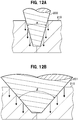
Fig.12A shows a cross-sectional view of a conventional joining rotary tool. -
Fig.12B shows a cross-sectional view of a conventional joining rotary tool. -
Fig.13 is a graph showing a result ofTEST 1 indicating a relation between a thickness of a burr and a fatigue strength. -
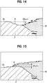
Fig.14 shows schematically a macro structure of a test piece P1 forTEST 1 around a boundary between a front face of a second metal member and a plasticized zone. -
Fig.15 shows schematically a macro structure of a test piece P2 forTEST 1 around a boundary between a front face of a second metal member and a plasticized zone. -
Fig.16 shows schematically a macro structure of a test piece P3 forTEST 1 around a boundary between a front face of a second metal member and a plasticized zone. -
Fig.17 shows schematically a macro structure of a test piece P4 forTEST 1 around a boundary between a front face of a second metal member and a plasticized zone. -
Fig.18 is a graph showing a relation between the target angle and the thickness of the burr, which is derived from results ofTEST 2. - An embodiment of the present invention is described with appropriate reference to the drawings. To begin with, a joining rotary tool (rotary tool) for the embodiment is described. The joining rotary tool is a tool to be used for friction-stir-welding. As shown in
Fig.1 , a joining rotary tool F consists mainly of a base shaft portion F1, a base side pin F2 and a tip side pin F3. The base shaft pin F1 is in a columnar shape and secured to a main shaft of a friction stir welding apparatus. - The base side pin F2 is formed to extend from the base shaft portion F1 and tapers to be thinner toward its tip. The base side pin F2 is in a conical shape with its tip portion cut off. The base side pin F2 has a taper angle A that may be appropriately formed to be, for example, between 135° and 160°. If the taper angle Ais smaller than 135° or larger than 160°, a surface roughness of the joined portion becomes large. The taper angle A is formed to be larger than a taper angle B of the tip side pin F3 to be described later. As shown in
Fig.2 , a pin step portion F21 in a staircase shape is formed over a whole outer circumferential face of the base side pin F2 in its height direction. The pin step portion F21 is formed in a clockwise or counterclockwise spiral shape. That is, the pin step portion F21 is seen in a spiral shape in its plan view and in a staircase shape in its side view. Since the joining rotary tool F is rotated clockwise for this embodiment, the pin step portion F21 is formed in the clockwise shape from a base side to a tip side of the base side pin F2. - Since the joining rotary tool F is rotated clockwise for this embodiment, the pin step portion F21 is preferably formed in the clockwise shape from a base side to a tip side of the base side pin F2. This enables reducing an amount of metal coming out of the metal members to be joined, because the plastically flowing material is directed toward the tip side of the base side pin F2 by the pin step portion F21. The pin step portion F21 is formed by a step bottom face F21a and a step side face F21b. A length X1 (horizontal direction length) between two apexes F21c, F21c next to each other of a pin step portions F21 is appropriately set based on a step angle C and a height Y1 of the step side face F21b, which are described later.
- The height Y1 of the step side face F21b may be appropriately set, for example, to between 0.1 and 0.4mm. If the height Y1 is smaller than 0.1mm, the joined portion has a relatively large surface roughness. On the other hand, if the height Y1 is larger than 0.4mm, the joined portion tends to have a relatively large surface roughness and the number of effective steps (number of steps of the pin step portion F21 being in contact with the metal member to be joined) becomes fewer.
- The step angle C made between the step bottom face F21a and the step side face F21b may appropriately set and, for example, to between 85° and 120°. The step bottom face F21a in this embodiment is in parallel with a horizontal plane. The step bottom face F21a may be inclined by between -5° and 15° relative to the horizontal plane from a rotation axis of the rotary tool toward its outer circumference (a minus angle corresponds to the step bottom face F21a extending outward inclining downward relative to the horizontal plane and a plus angle corresponds to the step bottom face F21a extending outward inclining upward relative to the horizontal plane). The length X1, the height Y1 of the step side face F21b, the step angle C and the angle of the step bottom face F21a relative to the horizontal plane are set in such a manner that the plastically flowing material flows out of the pin step portion F21 without being stuck on and adhering to the pin step portion F21 and is sufficiently held down by the step bottom face F21a for the joined portion to have a relatively small surface roughness.
- As shown in
Fig.1 , the tip side pin F3 is formed to extend continuously from the base side pin F2. The tip side pin F3 is in a conical shape with its tip portion cut off. The tip side pin F3 has a flat face that is formed on its tip portion. The tip side pin F3 has a taper angle B that is smaller than the taper angle A of the base side pin F2. As shown inFig.2 , a spiral groove F31 is engraved on an outer circumferential face of the tip side pin F3. The spiral groove F31 may be formed clockwise or counterclockwise. The spiral groove F31 may be engraved clockwise or counterclockwise from a base side to a tip side of the tip side pin F3 of the joining rotary tool F. However, since the joining rotary tool F is rotated clockwise in this embodiment, the spiral groove F31 is engraved counterclockwise from a base side to a tip side of the tip side pin F3 of the joining rotary tool F. - If the joining rotary tool F is rotated counterclockwise, the spiral groove F31 is preferably formed clockwise from the base side to the tip side of the tip side pin F3. This enables reducing an amount of metal coming out of the metal members to be joined, because the plastically flowing material is directed toward the tip side of the tip side pin F3 by the spiral groove F31. The spiral groove F31 is formed by a spiral bottom face F31a and a spiral side face F31b. A length X2 denotes a length (horizontal direction length) between two apexes F31c, F31c next to each other of a pin step portion F31. A height Y2 denotes a height of the spiral side face F31b. A spiral angle D made between the spiral bottom face F31a and the spiral side face F31b may be set, for example, to between 45° and 90°. The spiral groove F31 is intended to have a function of contacting metal members to be joined to increase friction heat and direct the plastically flowing material toward the tip side.
- The configuration of the joining rotary tool F may be appropriately modified.
Fig.3 is a side elevation view of a first modification example of the rotary tool of the present invention. As shown inFig.3 , a joining rotary tool FA of the first modification example has the step angle C between the step bottom face F21a of the pin step portion F21 and the pin step side face F21b of the pin step portion F21, the step angle being equal to 85°. The step bottom face 21a is in parallel with the horizontal plane. Thus, the step angle C may be set to such an acute angle that the plastically flowing material is able to come out of the pin step portion F21 without being stuck on and adhering to the pin step portion F21 while friction-stirring is being performed, if the step bottom face F21a is in parallel with the horizontal plane. -
Fig.4 is a side elevation view of a second modification example of the joining rotary tool of the present invention. As shown inFig.4 , a joining rotary tool FB of the second modification example has the step angle C of the pin step portion F21 being equal to 115°. The step bottom face F21a is in parallel with the horizontal plane. Thus, the step angle C may be set to an obtuse angle with the step bottom face F21a being in parallel with the horizontal plane as long as the pin step portion F21 functions as intended. -
Fig.5 is a side elevation view of a third modification example of the joining rotary tool of the present invention. As shown inFig.5 , a joining rotary tool FC has a step bottom face F21a extending from a rotation axis side toward an outer periphery inclining upward at 10° to the horizontal plane. The step side face F21b is in parallel with a vertical plane. Thus, the step bottom face F21a may be formed to incline upward relative to the horizontal plane from the rotation axis side toward an outer circumference as long as the plastically flowing material can be held down while friction-stirring is being performed. If any of the joining tools of the first to third modification examples above mentioned is used, an equivalent effect to that for the embodiments described below is obtained. - Next, the joining method of the embodiment is explained. The joining method of the embodiment includes a butting process and a joining process. In the description below, a "front face" means an opposite face of a "back face".
- The butting process is a process in which a
first metal member 1 is butted against asecond metal member 2, as shown inFig.6 . Thefirst metal member 1 and thesecond metal member 2 are made of a metal that can be friction-stirred such as aluminum, an aluminum alloy, copper, a copper alloy, titan, a titan alloy, magnesium, or a magnesium alloy. Thefirst metal member 1 and thesecond metal member 2 used for this embodiment are made of an aluminum alloy. Thefirst metal member 1 and thesecond metal member 2 used for this embodiment may be made different kinds of metals. - The
first metal member 1 has a larger thickness than thesecond metal member 2 does. Since aback face 1c of thefirst metal member 1 is flush with aback face 2c of thesecond metal member 2, there is a step at the butted portion J where end faces 1a, 2a are butted against each other. A thickness ratio between thefirst metal member 1 and thesecond metal member 2 may be appropriately set. For instance, if the thickness of thesecond metal member 2 is 1, the thickness of thefirst metal member 1 may be set to be between 1.2 and 2.5, preferably between 1.33 and 2.0. Alternatively, two metal members having an identical thickness may be butted against each other in the butting process in such a manner that there is a step between these metal members. - The joining process is a process in which friction-stir-welding is performed on the butted portion J with the joining rotary tool F as shown in
Fig.7 . In this joining process, the joining rotary tool F that is rotating clockwise is inserted into the butted portion J and made to move along the butted portion J. In this embodiment, thefirst metal member 1 is on the right side of the translation direction of the joining rotary tool F that is rotating clockwise. As a result, thesecond metal member 2 is on the advancing side while thefirst metal member 1 is retreating side. - The advancing side (shear side) is a side where a relative speed of an outer circumference of the joining rotary tool F relative to a portion to be joined corresponds to a summation of a tangent speed of the outer circumference of the joining rotary tool F that is rotating and a translation speed of the joining rotary tool F. On the contrary, the retreating side (flow side) corresponds to a side where the relative speed of the outer circumference of the joining rotary tool F relative to the portion to be joined becomes lower with the joining rotary tool F rotating in such a direction that the tangent speed of the circumference of the joining rotary tool F that is rotating is in the opposite direction to the translation direction of the joining rotary tool F.
- As shown in
Fig.8 , friction-stirring in the joining process is performed with a rotation axis U of the joining rotary tool F kept inclined by an inclination angle θ (target angle) toward thesecond metal member 2 relative to the butted face (end faces 1a,2a). A plasticized zone W is formed along the translation track along which the joining rotary tool F has moved. -
Figs.9 to 11 show cross-sectional views of the joining process illustrating a target angle. As shown inFig.9 , a contact point at which the outer circumferential face of the base side pin F2 intersects with thefront face 1b of thefirst metal member 1 in the cross-sectional view is referred to as an intersection point d and a point that is to be a rotational object of the intersection point d with respect to the rotation axis U is referred to as an intersection point e. Then, the target angle may be set to such an angle that the intersection point e is positioned on thefront face 2b of thesecond metal member 2 in the cross-sectional view. - Otherwise, as shown in
Fig.10 , the target angle may be set to such an angle that the intersection point e is positioned above thefront face 2b of thesecond metal member 2 in the cross-sectional view. However, if the intersection point e is too far away from thefront face 2b of thesecond metal member 2, the plastically flowing material cannot be held down sufficiently, and a burr formed on thefront face 2b of thesecond metal member 2 becomes thick. - On the other hand, as shown in
Fig.11 , if the intersection point e is positioned below thefront face 2b of thesecond metal member 2, an undercut portion is formed along the translation track along which the joining rotary tool F has moved, which is not preferable. - The inclination angle (target angle) θ may be appropriately set to such an angle that the thickness of the burr formed on the
front face 2b of thesecond metal member 2 becomes between 0 and 130 pm after the joining process. To be more specific, the inclination angle (target angle) θ is preferably set to such an angle that aninequality 1 of -0.05 θ + 0.16 ≤ s ≤-0.05 θ + 0.40 is met, where s (mm) denotes a thickness of the burr formed on thefront face 2b of thesecond metal member 2. - According to the joining method of the embodiment as has been described, the
front face 1b of thefirst metal member 1 and thefront face 2b of thesecond metal member 2 are held down by the outer circumferential face of the base side pin F2 whose taper angle is larger with the joining rotary tool F kept inclined toward thesecond metal member 2. As a result, the resultant burr can be made smaller, and the joint strength can be increased. If the thickness of the burr is smaller than 0, which corresponds to an undercut portion being formed, the joint strength decreases. Alternatively, if the thickness of the burr exceeds 130 pm, the joint portion is short of metal, which results in the joint strength becoming lower. - In this joining method, for instance, if a
conventional rotary tool 200 is used as shown inFig.12A , an uneven concave groove (concave groove formed by the front face of the joined metal member and the surface of the plasticized zone) becomes large and the joined portion has a relatively large surface roughness, because a front face of the joinedmetal member 210 is not held down. In addition, there is a problem with a raised portion (a portion that is formed by the front face of the joined metal member being raised compared with the front face before joined) being formed near the uneven concave groove. Alternatively, if arotary tool 201 having a taper angle β that is larger than the taper angle α of therotary tool 200 as is shown inFig.12B , the uneven concave groove becomes smaller and the raised portion becomes smaller as well, because the front face of the joinedmetal member 210 is held down sufficiently. However, a kissing-bond is easily formed under the plasticized zone, because the stronger downward plastically flowing of metal occurs. - On the other hand, the joining rotary tool F of the embodiment includes the base side pin F2 and the tip side pin F3 whose taper angle is smaller than the taper angle A of the base side pin F2. This structure makes it easier to insert the joining rotary tool F into the butted portion J. In addition, since the taper angle B of the tip side pin F3 is smaller, the joining rotary tool F can be easily inserted to a deep position in the butted portion J. In addition, since the taper angle B of the tip side pin F3 is smaller, the downward plastically flowing of friction-stirred material is reduced compared with the
rotary tool 201. As a result, it is possible to prevent a kissing-bond from being formed under the plasticized zone W. In addition, since the taper angle A of the base side pin F2 is larger, joining can be stably more performed than with the conventional rotary tool if the thickness of the metal member to be joined or the height at which joining is done varies. - Additionally, since the plastically flowing material can be held down by the outer circumferential face of the base side pin F2, the uneven concave groove formed on the surface of the joined portion is made small and the raised portion that can be formed near the uneven concave groove is not formed or can be made smaller. In addition, since the pin step portion F21 is shallow and has a wide exit, the plastically flowing material can easily move out of the pin step portion F21 while the plastically flowing material is being held down by the step bottom face F21a. Therefore, the plastically flowing material cannot easily get stuck on and adhere to the outer circumferential face of the base side pin F2. As a result, it is possible to inhibit a burr being formed, make the surface roughness of joined portion smaller and stabilize the joining quality.
- Two kinds of tests,
TEST 1 andTEST 2 have been carried out.TEST 1 is intended to examine a relation between the thickness of the burr and a fatigue strength andTEST 2 is intended to examine a relation between the thickness of the burr and the inclination angle (target angle) θ of the joining rotary tool F. InTEST 1, thefirst metal members 1 and thesecond metal members 2, both of which are made of an aluminum alloy, A5052, were prepared. The fatigue strength of each of these members is 120 MPa. There were five test pieces, P1 to P5, prepared forTEST 1. The inclination angles (target angle) θ that were tested were an inclination angle θ1 for the test piece P1, an inclination angle θ2 for the test piece P2, an inclination angle θ3 for the test piece P3, an inclination angle θ4 for the test piece P4 and an inclination angle θ5 for the test piece P5. These inclination angles vary according to a relation of θ1 > θ2 > θ3 > θ4 > θ5. - The test piece P1 was prepared through the joining process with the intersection point e kept below the
front face 2b of thesecond metal member 2 as shown inFig.11 . An undercut portion K was formed on thefront face 2b of thesecond metal member 2 of the test piece P1, as shown inFig. 14 . A depth of the undercut portion was approximately 66 pm. For the convenience of description, the depth of this undercut portion K is referred to as "burr thickness = - 66 pm". That is, when the burr thickness is less than 0, it follows that there is an undercut portion K formed on thefront face 2b of thesecond metal member 2. - As shown in
Fig.13 , the fatigue strength of the test piece P1 was approximately 52 MPa, which was lower than thethreshold value 60 MPa. That is, the fatigue strength of the test piece P1 was low because of the undercut portion K formed on the front face K of thesecond metal member 2. - The test piece P2 was prepared through the joining process with the intersection point e kept above the
front face 2b of thesecond metal member 2, as shown inFig. 10 . A burr S was formed on thefront face 2b of thesecond metal member 2 of the test piece P2 as shown inFig.15 . The thickness of the burr S (which was a height from thefront face 2b of thesecond metal member 2 to a top of the burr S) was 23 µm. As shown inFig.13 , the fatigue strength of the test piece P2 was approximately 109MPa, which was the highest value. That is, the test piece P2 had the smallest burr S and the highest fatigue strength. - The test piece P3 was prepared through the joining process with the intersection point e kept above the
front face 2b of thesecond metal member 2, as shown inFig. 10 . The intersection point e for the test piece P3 was set at a higher position than the intersection point e for the test piece P2. A burr S was formed on thefront face 2b of thesecond metal member 2 of the test piece P3, as shown inFig.16 . The thick ness of the burr S was 57 pm. As shown inFig.13 , the fatigue strength of the test piece P3 was approximately 88 MPa, which was the second highest value. - The test piece P4 was prepared through the joining process with the intersection point e kept above the
front face 2b of thesecond metal member 2. The intersection point e for the test piece P4 was set a higher position than the intersection point e for the test piece P3. A burr S was formed on thefront face 2b of thesecond metal member 2 of the test piece P4, as shown inFig.17 . The thickness of the burr S was 93 pm. As shown inFig.13 , the fatigue strength of the test piece P4 was approximately 70 MPa, which was the third highest value. - The test piece P5 was prepared through the joining process with the intersection point e kept above the
front face 2b of thesecond metal member 2, as shown inFig. 10 . The intersection point e for the test piece P5 was set as a higher position than the intersection point e for the test piece P4. The burr S formed on the test piece P5, which is not shown, is larger than the burr S formed on the test piece P4. As shown inFig.13 , the fatigue strength of the test piece P5 was approximately 58 MPa, which was less than the threshold value. This indicates that the joint strength of the test piece lowers if the burr S becomes too large like the test piece P5. - The results of
TEST 1 are summarized as follows. If the inclination angle (target angle) θ is too large, which is the case with thetest piece 1, the fatigue strength lowers due to the formation of the undercut portion, which is not a preferable result. On the other hand, if the inclination angle (target angle) θ of the joining rotary tool F is too small, which corresponds to the test piece P5, the plastically flowing material cannot be sufficiently held down and the thickness of the burr becomes larger, which is not a preferable result. In the case of each of the test pieces P2 to P4, the thickness of the burr can be kept relatively small, and the fatigue strength does not lower to the threshold value and is within an acceptable range. In other words, it is preferable to set the inclination angle (target angle) θ of the joining rotary tool F to perform the joining process to such an angle that the thickness of the burr becomes between 0 and 130 µm. - In
TEST 2, the thickness ratio of thefirst metal member 1 to thesecond metal member 2 was varied and three thickness ratios, which were "1 : 2.0 forCASE 1", "1 : 1.67 forCASE 2" and "1 : 1.33 for CASE 3", were tested. For each of the tested cases, test pieces were prepared through the joining processes with various inclination angles (target angle) θ. InCASE 1, three inclination angles (target angle) θ, 0°, 3°, 6°, were tested and the joining process was performed with each of the inclination angles (target angle) θ. InCASE 2, seven inclination angles (target angle) θ, 0°, 2°, 4°, 5°, 6°, 7°, 8°, were tested and the joining process was performed with each of the inclination angles (target angle) θ. In CASE 3, two inclination angles (target angle) θ, 2°, 3°, were tested and the joining process was performed with each of the inclination angles (target angle) θ. - As shown in
Fig. 18 , when the inclination angle (target angle) θ of the joining rotary tool F is 0° inCASE 1, the thickness of the burr S formed on thefront face 2b of thesecond metal member 2 is 0.4 mm (400 µm), which is the largest. On the other hand, when the inclination angle (target angle) θ of the joining rotary tool F is 6° inCASE 1, the thickness of the burr S is smaller than 0.13 mm (130 µm), which is a preferable result. - As shown in
Fig. 18 , when the inclination angle (target angle) θ of the joining rotary tool F is 0° inCASE 2, the thickness of the burr S formed on thefront face 2b of thesecond metal member 2 is 0.35 mm (350 µm), which is the largest. On the other hand, when the inclination angle (target angle) θ of the joining rotary tool F is 8° inCASE 2, the thickness of the burr S is less than 0 (the undercut portion K is formed). When the inclination angle (target angle) θ of the joining rotary tool F is between 4°and 7°, the thickness of the burr is between 0 and 0.13 mm (0 ~ 130 µm), which is preferable. - As shown in
Fig. 18 , when the inclination angle (target angle) θ of the joining rotary tool F for CASE 3 is between 0.5°and 3°, the thickness of the burr is between 0 and 0.13 mm (0 ~ 130 µm), which is preferable. - Based on the comparison of
CASE 1 to CASE 3, it is noted that the inclination angle (target angle) θ of the joining rotary tool F needs to be set to a larger angle forCASE 1, which has a larger difference in the plate thickness between thefirst metal member 1 and thesecond metal member 2, than for CASE 3. On the contrary, the inclination angle (target angle) θ of the joining rotary tool F needs to be set to a smaller angle for CASE 3 having a smaller difference in the plate thickness between thefirst metal member 1 and thesecond metal member 2 than forCASE 1. It has turned out that the undercut portion K formed for CASE 3 tends to be larger if the inclination angle (target angle) θ is set to larger than 4°. - A method of least squares was applied to the result of
CASE 1 and a correlation of Ya = - 0.05 θ + 0.40 was obtained. The method of least squares was applied to the result ofCASE 2 and a correlation of Yb = - 0.05 θ+ 0.35 was obtained. The method of least squares was also applied to the result of CASE 3 and a correlation of Yc = - 0.05 θ + 0.16 was obtained. When the thickness ratio of thefirst metal member 1 to thesecond metal member 2 is between 1.33 and 2, it is preferable that the rotation axis U of the joining rotary tool F is inclined toward thesecond metal member 2 so that the thickness of the resultant burr is between 0 and 130 pm while the inclination angle (target angle) θ (°) of the joining rotary tool F is set to such an angle that an inequality of ― 0.05 θ + 0.16 ≤ s ≤ -0.05 θ + 0.40 is met, where s is the thickness of the burr S in mm. -
- 1
- First Metal Member
- 2
- Second Metal Member
- F
- Primary Joining Rotary Tool (Rotary Tool)
- F2
- Base Side Pin
- F3
- Tip Side Pin
- J
- Butted Portion
- S
- Burr
- W
- Plasticized Zone
Claims (3)
- Ajoining method comprising;a butting process of butting an end face of a first metal member and an end face of a second metal member against each other to form a butted portion that is stepped with a second front face of the second metal member being lower than a first front face of the first metal member; anda joining process of performing friction-stir-welding on the butted portion that is stepped with a rotary tool,wherein the rotary tool includes a base side pin and a tip side pin, a taper angle of the base side pin is larger than a taper angle of the tip side pin, and a pin step portion in a staircase shape is formed on an outer circumferential face of the base side pin, andwherein in the joining process, a rotation direction and a translation method of the rotary tool are set to such directions that the second metal member is on an advancing side, a target angle by which a rotation axis of the rotary tool is inclined toward the second metal member is set to such an angle that a burr formed after the joining process on the second front face of the second metal member has a thickness between 0 and 130 pm, and friction-stirring is performed with the target angle of the rotary tool kept unchanged and with a plastically flowing material being held down by a step bottom face of the pin step portion in the joining process.
- The joining method as claimed in claim 1, wherein the target angle is set to such an angle that in a cross-sectional plane that includes a rotation axis of the rotary tool and is perpendicular to a translation direction in which the rotary tool moves, an intersection point e is positioned on or above the second front face of the second metal member, where the intersection point e is a point to be a rotational object of an intersection point d with respect to the rotation axis, the intersection point d being an intersection point between the outer circumferential face of the base side pin and the first front face of the first metal member.
- The joining method as claimed in claim 1 or 2, wherein the target angle is set to such an angle that an inequality of ― 0.05 θ + 0.16 ≤ s ≤ -0.05 θ + 0.40 is met, where s is the thickness of the burr in mm and θ is the target angle (°), when a thickness ratio of the first metal member to the second metal member is between 1.33 and 2.
Applications Claiming Priority (2)
| Application Number | Priority Date | Filing Date | Title |
|---|---|---|---|
| JP2018236943A JP7070389B2 (en) | 2018-12-19 | 2018-12-19 | Joining method |
| PCT/JP2019/023829 WO2020129281A1 (en) | 2018-12-19 | 2019-06-17 | Joining method |
Publications (3)
| Publication Number | Publication Date |
|---|---|
| EP3900868A1 true EP3900868A1 (en) | 2021-10-27 |
| EP3900868A4 EP3900868A4 (en) | 2022-09-28 |
| EP3900868B1 EP3900868B1 (en) | 2024-10-09 |
Family
ID=71102694
Family Applications (1)
| Application Number | Title | Priority Date | Filing Date |
|---|---|---|---|
| EP19898076.5A Active EP3900868B1 (en) | 2018-12-19 | 2019-06-17 | Joining method |
Country Status (5)
| Country | Link |
|---|---|
| US (1) | US11707799B2 (en) |
| EP (1) | EP3900868B1 (en) |
| JP (1) | JP7070389B2 (en) |
| CN (1) | CN112672842B (en) |
| WO (1) | WO2020129281A1 (en) |
Families Citing this family (7)
| Publication number | Priority date | Publication date | Assignee | Title |
|---|---|---|---|---|
| JP2019058934A (en) | 2017-09-27 | 2019-04-18 | 日本軽金属株式会社 | Manufacturing method of liquid-cooled jacket |
| JP2019058933A (en) | 2017-09-27 | 2019-04-18 | 日本軽金属株式会社 | Manufacturing method of liquid-cooled jacket |
| JP6769427B2 (en) | 2017-12-18 | 2020-10-14 | 日本軽金属株式会社 | How to manufacture a liquid-cooled jacket |
| JP2019181473A (en) | 2018-04-02 | 2019-10-24 | 日本軽金属株式会社 | Liquid-cooled jacket manufacturing method |
| JP6927128B2 (en) | 2018-04-02 | 2021-08-25 | 日本軽金属株式会社 | How to manufacture a liquid-cooled jacket |
| CN112770863B (en) | 2018-10-11 | 2022-07-29 | 川崎重工业株式会社 | Friction stir welding device, method of operating the same, and joint structure |
| WO2021025155A1 (en) * | 2019-08-08 | 2021-02-11 | 日本軽金属株式会社 | Automatic joining system |
Family Cites Families (99)
| Publication number | Priority date | Publication date | Assignee | Title |
|---|---|---|---|---|
| EP0730799A1 (en) | 1994-09-23 | 1996-09-11 | Koninklijke Philips Electronics N.V. | Optical unit for restoring a pulse pattern, and receiver suitable for use in a transmission system comprising such a unit |
| TW294810B (en) | 1994-09-23 | 1997-01-01 | Philips Electronics Nv | |
| US6325273B1 (en) | 1996-12-06 | 2001-12-04 | The Lead Sheet Association | Friction welding apparatus and method |
| JP3070735B2 (en) | 1997-07-23 | 2000-07-31 | 株式会社日立製作所 | Friction stir welding method |
| JPH11267859A (en) | 1998-03-17 | 1999-10-05 | Sumitomo Light Metal Ind Ltd | Processed material for joining, joining method thereof, and joined processed panel |
| US6421578B1 (en) | 1999-02-12 | 2002-07-16 | Lockheed Martin Corporation | Stir-friction hot working control system |
| JP2000246465A (en) | 1999-02-25 | 2000-09-12 | Showa Alum Corp | Tools for friction stir welding |
| JP3452018B2 (en) * | 2000-03-24 | 2003-09-29 | 日本軽金属株式会社 | Joining method and joining tool |
| JP4545368B2 (en) | 2000-05-08 | 2010-09-15 | ブリガム ヤング ユニバーシティ | Friction stir welding of metal matrix composites, ferrous alloys, non-ferrous alloys and superalloys using high wear resistant tools |
| JP4467723B2 (en) | 2000-06-30 | 2010-05-26 | 昭和電工株式会社 | Friction stir welding method |
| WO2002024393A1 (en) | 2000-09-21 | 2002-03-28 | Showa Denko K.K. | Friction agitation joining tool, friction agitation joining method and joined member manufacturing method |
| CN100553851C (en) * | 2001-03-07 | 2009-10-28 | 昭和电工株式会社 | Friction agitation joining method and method for manufacturing joined butted members |
| JP2002346766A (en) | 2001-05-28 | 2002-12-04 | Hitachi Ltd | Friction stir welding method for members with different thickness |
| US7097091B2 (en) | 2001-07-25 | 2006-08-29 | Hitachi, Ltd. | Friction stir welding method and component part welded by the method |
| JP4672202B2 (en) | 2001-08-01 | 2011-04-20 | マツダ株式会社 | Rotating tool, member processing method and surface processing method using the rotating tool |
| US6669075B2 (en) | 2002-05-07 | 2003-12-30 | Concurrent Technologies Corporation | Tapered friction stir welding tool |
| US20060151576A1 (en) | 2002-07-08 | 2006-07-13 | Honda Giken Kogyo Kabushiki Kaisha | Manufacturing method of butt joint, butt joint, manufacturing method of bent member, and friction stir joining method |
| JP2004106037A (en) | 2002-09-20 | 2004-04-08 | Hitachi Ltd | How to join metal materials |
| JP4325260B2 (en) | 2003-04-15 | 2009-09-02 | 日本軽金属株式会社 | Manufacturing method of heat transfer element |
| US7494040B2 (en) | 2003-09-25 | 2009-02-24 | Sii Megadiamond, Inc. | Friction stir welding improvements for metal matrix composites, ferrous alloys, non-ferrous alloys, and superalloys using a superabrasive tool |
| US20050246884A1 (en) | 2004-02-27 | 2005-11-10 | Chan-Tung Chen | Friction welding structure for striking plate of golf club head and method therefor |
| US7275675B1 (en) | 2004-08-20 | 2007-10-02 | United States Of America As Represented By The Administrator Of The National Aeronautics And Space Administration | Friction stir weld tools |
| US7234626B2 (en) | 2004-10-22 | 2007-06-26 | Edison Welding Institute, Inc. | Method of friction stir welding and retractable shoulderless variable penetration friction stir welding tool for same |
| JP4804011B2 (en) | 2005-02-02 | 2011-10-26 | 住友軽金属工業株式会社 | Friction stir spot welding method |
| US7992759B2 (en) | 2005-06-10 | 2011-08-09 | Megastir Technologies, LLC | Two spiral stepped friction stir welding tool |
| JP2007160370A (en) | 2005-12-15 | 2007-06-28 | Hino Motors Ltd | Friction stir welding tool |
| TWI294810B (en) | 2005-12-29 | 2008-03-21 | Metal Ind Res & Dev Ct | Method and structure for jointing hybrid materials |
| JP5061098B2 (en) | 2006-03-16 | 2012-10-31 | 昭和電工株式会社 | Friction stir welding method |
| US20070241163A1 (en) | 2006-04-17 | 2007-10-18 | Valant Michael E | Apparatus And Method For Friction Stir Spot Welding |
| JP4770661B2 (en) | 2006-09-19 | 2011-09-14 | マツダ株式会社 | Friction spot welding method |
| US7555359B2 (en) | 2006-10-06 | 2009-06-30 | Hitachi, Ltd | Apparatus and method for correcting defects by friction stir processing |
| US7942306B2 (en) | 2007-04-13 | 2011-05-17 | Wichita State University | Friction stir welding tool having a counterflow pin configuration |
| CN101952079B (en) | 2008-02-21 | 2014-04-02 | 日本轻金属株式会社 | Manufacturing method of heat transfer plate |
| JP4962423B2 (en) | 2008-06-16 | 2012-06-27 | 日本軽金属株式会社 | Manufacturing method of heat transfer plate |
| US20110180587A1 (en) | 2008-06-26 | 2011-07-28 | Edison Welding Institute, Inc. | Friction stir welding tool |
| JP2010036230A (en) | 2008-08-06 | 2010-02-18 | Toshiba Corp | Friction stir treating method of dissimilar material joining part, and friction stir welding method of dissimilar material |
| JP4924573B2 (en) | 2008-08-28 | 2012-04-25 | 日本軽金属株式会社 | Friction stir welding method for double skin panels |
| CN101670481B (en) | 2008-09-11 | 2012-05-23 | 汉翔航空工业股份有限公司 | Friction stir welding cutter and welding structure |
| US20100081005A1 (en) | 2008-09-26 | 2010-04-01 | Jong-Ning Aoh | Friction Stir Welding Tool and Weld Metal Structure with Plural Onion Rings |
| JP5262822B2 (en) | 2009-02-23 | 2013-08-14 | 日本軽金属株式会社 | Manufacturing method of liquid cooling jacket |
| JP5519166B2 (en) | 2009-03-05 | 2014-06-11 | 本田技研工業株式会社 | Friction stir welding method |
| JP2012530608A (en) | 2009-06-26 | 2012-12-06 | イーエスエービー エービー | Method and apparatus for friction stir spot welding using a number of shoulders suitable for the thickness of the spot welded plate |
| JP5304583B2 (en) | 2009-10-09 | 2013-10-02 | 日本軽金属株式会社 | Rotating tool for inner corner joining and inner corner joining method using the same |
| KR20110088266A (en) | 2010-01-28 | 2011-08-03 | 주식회사 에이치엠 | Probe for Friction Welding |
| US20110309131A1 (en) | 2010-06-18 | 2011-12-22 | Battelle Memorial Institute | Friction stir welding tool and process for welding dissimilar materials |
| JP5514782B2 (en) * | 2010-09-24 | 2014-06-04 | 株式会社Uacj | Rotational welding tool for friction stir welding, and friction stir welding method using the same |
| JP2012125822A (en) | 2010-12-16 | 2012-07-05 | Mitsubishi Heavy Ind Ltd | Tool for friction stir welding, and method for repairing crack |
| JP2012218001A (en) | 2011-04-05 | 2012-11-12 | Furukawa-Sky Aluminum Corp | Friction stir welding method |
| JP5492235B2 (en) | 2011-06-21 | 2014-05-14 | 日本軽金属株式会社 | Double skin panel assembly and friction stir welding method for double skin panel |
| JP5957719B2 (en) | 2011-08-19 | 2016-07-27 | 日本軽金属株式会社 | Friction stir welding method |
| US9095927B2 (en) | 2011-08-19 | 2015-08-04 | Nippon Light Metal Company, Ltd. | Friction stir welding method |
| US8910851B2 (en) | 2011-09-20 | 2014-12-16 | Megastir Technologies Llc | Material surface modification using friction stir welding hybrid process |
| DE102012001877B4 (en) | 2012-02-01 | 2014-01-09 | Christoph Lenz | Kaltnahtstichel for producing a media-tight seam |
| WO2013150801A1 (en) | 2012-04-06 | 2013-10-10 | Jfeスチール株式会社 | Method for friction-stir welding of steel sheet |
| JP6076004B2 (en) | 2012-09-06 | 2017-02-08 | 株式会社Uacj | Rotating tool for friction stir spot welding and friction stir spot welding method using the same |
| JP2014094409A (en) | 2012-10-10 | 2014-05-22 | Nippon Light Metal Co Ltd | Method of producing heat exchanger plate and friction agitation joining method |
| DE102013000574B4 (en) | 2013-01-15 | 2018-03-29 | Audi Ag | Friction friction welding device and method for friction stir welding |
| CN203209851U (en) | 2013-05-07 | 2013-09-25 | 凯迈(洛阳)置业包装有限公司 | Friction stir welding head and stirring pin thereof |
| EP2810735B1 (en) | 2013-06-05 | 2016-08-10 | Airbus Defence and Space GmbH | Friction stir welding tool and method with a non-circumferential shoulder |
| US20140367452A1 (en) | 2013-06-18 | 2014-12-18 | Focus: Hope | Method of friction stir welding |
| CN103521912B (en) | 2013-10-10 | 2015-11-25 | 天津大学 | A kind of friction stir welding tools for lap joint |
| CN104646820B (en) | 2013-11-25 | 2017-07-21 | 中国兵器工业第五二研究所 | A kind of stirring-head welded for aluminium alloy thick plate and its welding method |
| JP6036714B2 (en) | 2014-01-14 | 2016-11-30 | 日本軽金属株式会社 | Manufacturing method of liquid cooling jacket |
| US9999941B2 (en) | 2014-01-14 | 2018-06-19 | Nippon Light Metal Company, Ltd. | Method of manufacturing liquid-cooled jacket |
| JP6036715B2 (en) | 2014-01-14 | 2016-11-30 | 日本軽金属株式会社 | Manufacturing method of liquid cooling jacket |
| CN103949769A (en) | 2014-05-05 | 2014-07-30 | 西北工业大学 | Stirring head for friction stir welding used for welding parts with different thicknesses and welding method |
| CN104014926B (en) | 2014-05-30 | 2016-08-17 | 北京赛福斯特技术有限公司 | Aclinal is from upset agitating friction welding method and instrument |
| US10695861B2 (en) | 2014-07-10 | 2020-06-30 | Mazak Corporation | Friction stir extrusion of nonweldable materials for downhole tools |
| JP6471461B2 (en) | 2014-11-05 | 2019-02-20 | 日本軽金属株式会社 | Manufacturing method of liquid cooling jacket |
| US10471557B2 (en) | 2014-11-05 | 2019-11-12 | Nippon Light Metal Company, Ltd. | Method of manufacturing liquid-cooled jacket and liquid-cooled jacket |
| JP6471462B2 (en) | 2014-11-05 | 2019-02-20 | 日本軽金属株式会社 | Manufacturing method of liquid cooling jacket |
| KR20160071483A (en) | 2014-12-11 | 2016-06-22 | 조선대학교산학협력단 | Method For Welding iron and steel By Hybrid Friction Stir Welding |
| JP6350334B2 (en) | 2015-02-19 | 2018-07-04 | 日本軽金属株式会社 | Joining method and composite rolled material manufacturing method |
| WO2016163214A1 (en) | 2015-04-07 | 2016-10-13 | 三菱電機株式会社 | Friction stir welding method and welded structure |
| JP2016215264A (en) * | 2015-05-26 | 2016-12-22 | 株式会社東芝 | Friction stir welding tool and friction stir welding apparatus |
| DE102015112416A1 (en) | 2015-07-29 | 2017-02-02 | Universität Stuttgart | Method for friction stir welding and friction stir welded workpiece |
| JP6372516B2 (en) | 2015-08-26 | 2018-08-15 | 日本軽金属株式会社 | Liquid cooling jacket manufacturing method and liquid cooling jacket |
| US20190039168A1 (en) * | 2016-02-09 | 2019-02-07 | Nippon Light Metal Company, Ltd. | Joining method |
| CN105772935A (en) | 2016-04-01 | 2016-07-20 | 中国电子科技集团公司第三十八研究所 | Stirring head used for welding narrow-step water channel cover plate and welding technology for narrow-step water channel cover plate |
| MX2019003213A (en) | 2016-09-22 | 2019-09-10 | Nemak Sab De Cv | Method for the production of a cast engine block for a combustion engine and engine block. |
| DE112018000895T5 (en) | 2017-02-17 | 2019-10-31 | Mitsubishi Electric Corporation | REINFORCING WELDING METHOD AND METHOD FOR PRODUCING A WELDING STRUCTURE |
| CN110300636B (en) | 2017-04-18 | 2021-08-03 | 日本轻金属株式会社 | Manufacturing method of liquid cooling jacket |
| JP6885263B2 (en) | 2017-08-22 | 2021-06-09 | 日本軽金属株式会社 | How to manufacture a liquid-cooled jacket |
| JP2019058933A (en) | 2017-09-27 | 2019-04-18 | 日本軽金属株式会社 | Manufacturing method of liquid-cooled jacket |
| JP2019058934A (en) | 2017-09-27 | 2019-04-18 | 日本軽金属株式会社 | Manufacturing method of liquid-cooled jacket |
| JP7003589B2 (en) | 2017-11-15 | 2022-01-20 | 日本軽金属株式会社 | Joining method |
| EP3486021B1 (en) | 2017-11-21 | 2023-05-03 | Megastir Technologies LLC | Friction stir processing tool with radial protrusion |
| JP6769427B2 (en) | 2017-12-18 | 2020-10-14 | 日本軽金属株式会社 | How to manufacture a liquid-cooled jacket |
| JP2019107665A (en) | 2017-12-18 | 2019-07-04 | 日本軽金属株式会社 | Method for manufacturing liquid-cooled jacket |
| JP6927068B2 (en) * | 2018-02-01 | 2021-08-25 | 日本軽金属株式会社 | How to manufacture a liquid-cooled jacket |
| JP6927067B2 (en) * | 2018-02-01 | 2021-08-25 | 日本軽金属株式会社 | How to manufacture a liquid-cooled jacket |
| CN111032268B (en) | 2018-03-16 | 2022-04-22 | 日本轻金属株式会社 | Method for manufacturing heat conductive plate and friction stir welding method |
| JP6770014B2 (en) * | 2018-03-19 | 2020-10-14 | Primetals Technologies Japan株式会社 | An ironing plate for a friction stir welding device, a friction stir welding device equipped with the ironing plate, and a friction stir welding method. |
| JP6927128B2 (en) | 2018-04-02 | 2021-08-25 | 日本軽金属株式会社 | How to manufacture a liquid-cooled jacket |
| JP2019181473A (en) | 2018-04-02 | 2019-10-24 | 日本軽金属株式会社 | Liquid-cooled jacket manufacturing method |
| US10569356B1 (en) * | 2018-04-18 | 2020-02-25 | Seagate Technology Llc | Deburring tool for friction stir welding, and related methods |
| JP2020032429A (en) | 2018-08-27 | 2020-03-05 | 日本軽金属株式会社 | Heat transfer plate manufacturing method |
| JP2020075255A (en) | 2018-11-05 | 2020-05-21 | 日本軽金属株式会社 | Liquid cooling jacket manufacturing method and friction stir welding method |
| JP2020124715A (en) | 2019-02-01 | 2020-08-20 | 日本軽金属株式会社 | Joining method |
-
2018
- 2018-12-19 JP JP2018236943A patent/JP7070389B2/en active Active
-
2019
- 2019-06-17 CN CN201980058934.1A patent/CN112672842B/en active Active
- 2019-06-17 EP EP19898076.5A patent/EP3900868B1/en active Active
- 2019-06-17 WO PCT/JP2019/023829 patent/WO2020129281A1/en not_active Ceased
- 2019-06-17 US US17/285,062 patent/US11707799B2/en active Active
Also Published As
| Publication number | Publication date |
|---|---|
| US11707799B2 (en) | 2023-07-25 |
| CN112672842A (en) | 2021-04-16 |
| CN112672842B (en) | 2022-11-22 |
| EP3900868B1 (en) | 2024-10-09 |
| US20210346979A1 (en) | 2021-11-11 |
| EP3900868A4 (en) | 2022-09-28 |
| JP2020097045A (en) | 2020-06-25 |
| JP7070389B2 (en) | 2022-05-18 |
| WO2020129281A1 (en) | 2020-06-25 |
Similar Documents
| Publication | Publication Date | Title |
|---|---|---|
| EP3900868B1 (en) | Joining method | |
| EP3260230B1 (en) | Joining method and method for manufacturing composite rolled material | |
| EP3711892B1 (en) | Joining method | |
| EP1324854B1 (en) | Friction agitation joining tool, friction agitation joining method and joined member manufacturing method | |
| US8016179B2 (en) | Friction stir welding tool having a scroll-free concentric region | |
| Threadgill | Terminology in friction stir welding | |
| US7661575B2 (en) | Friction stirring-welding method | |
| EP1429887B1 (en) | Joining of structural members by friction plug welding | |
| JP3452018B2 (en) | Joining method and joining tool | |
| EP3098015A1 (en) | Friction stir welding method | |
| EP3878593A1 (en) | Liquid-cooled jacket manufacturing method and friction stir welding method | |
| EP3475024B1 (en) | A process for solid-state production of a channel and a weld joint | |
| US20190275607A1 (en) | Friction stir welding tool, friction stir welding apparatus, and friction stir welding method | |
| WO2020158081A1 (en) | Joining method | |
| JP7332050B2 (en) | Element, friction element joining method and friction element joining joint manufacturing method | |
| CN100513046C (en) | Friction stir welding method, jig, and member having friction stir welding head | |
| EP4424451A1 (en) | Method for manufacturing joined body | |
| US7530487B2 (en) | Method of welding onto thin components | |
| US20250264125A1 (en) | Fastener | |
| CN111468768A (en) | Rotary cutter for producing honing passages | |
| CN114901417B (en) | Manufacturing method of liquid cooling jacket and friction stir welding method | |
| US20260054319A1 (en) | Method for manufacturing joined body | |
| JP2015120203A (en) | Friction stir welding method | |
| JP2006150409A (en) | Aluminum or aluminum alloy material for friction stir spot welding and friction stir spot welding method |
Legal Events
| Date | Code | Title | Description |
|---|---|---|---|
| STAA | Information on the status of an ep patent application or granted ep patent |
Free format text: STATUS: THE INTERNATIONAL PUBLICATION HAS BEEN MADE |
|
| PUAI | Public reference made under article 153(3) epc to a published international application that has entered the european phase |
Free format text: ORIGINAL CODE: 0009012 |
|
| STAA | Information on the status of an ep patent application or granted ep patent |
Free format text: STATUS: REQUEST FOR EXAMINATION WAS MADE |
|
| 17P | Request for examination filed |
Effective date: 20210413 |
|
| AK | Designated contracting states |
Kind code of ref document: A1 Designated state(s): AL AT BE BG CH CY CZ DE DK EE ES FI FR GB GR HR HU IE IS IT LI LT LU LV MC MK MT NL NO PL PT RO RS SE SI SK SM TR |
|
| DAV | Request for validation of the european patent (deleted) | ||
| DAX | Request for extension of the european patent (deleted) | ||
| A4 | Supplementary search report drawn up and despatched |
Effective date: 20220824 |
|
| RIC1 | Information provided on ipc code assigned before grant |
Ipc: B23K 101/18 20060101ALN20220819BHEP Ipc: B23K 20/12 20060101AFI20220819BHEP |
|
| P01 | Opt-out of the competence of the unified patent court (upc) registered |
Effective date: 20230418 |
|
| GRAP | Despatch of communication of intention to grant a patent |
Free format text: ORIGINAL CODE: EPIDOSNIGR1 |
|
| STAA | Information on the status of an ep patent application or granted ep patent |
Free format text: STATUS: GRANT OF PATENT IS INTENDED |
|
| RIC1 | Information provided on ipc code assigned before grant |
Ipc: B23K 101/18 20060101ALN20240710BHEP Ipc: B23K 20/12 20060101AFI20240710BHEP |
|
| GRAS | Grant fee paid |
Free format text: ORIGINAL CODE: EPIDOSNIGR3 |
|
| INTG | Intention to grant announced |
Effective date: 20240731 |
|
| GRAA | (expected) grant |
Free format text: ORIGINAL CODE: 0009210 |
|
| STAA | Information on the status of an ep patent application or granted ep patent |
Free format text: STATUS: THE PATENT HAS BEEN GRANTED |
|
| AK | Designated contracting states |
Kind code of ref document: B1 Designated state(s): AL AT BE BG CH CY CZ DE DK EE ES FI FR GB GR HR HU IE IS IT LI LT LU LV MC MK MT NL NO PL PT RO RS SE SI SK SM TR |
|
| REG | Reference to a national code |
Ref country code: CH Ref legal event code: EP |
|
| REG | Reference to a national code |
Ref country code: DE Ref legal event code: R096 Ref document number: 602019060304 Country of ref document: DE |
|
| REG | Reference to a national code |
Ref country code: IE Ref legal event code: FG4D |
|
| REG | Reference to a national code |
Ref country code: LT Ref legal event code: MG9D |
|
| REG | Reference to a national code |
Ref country code: NL Ref legal event code: MP Effective date: 20241009 |
|
| REG | Reference to a national code |
Ref country code: AT Ref legal event code: MK05 Ref document number: 1730055 Country of ref document: AT Kind code of ref document: T Effective date: 20241009 |
|
| PG25 | Lapsed in a contracting state [announced via postgrant information from national office to epo] |
Ref country code: NL Free format text: LAPSE BECAUSE OF FAILURE TO SUBMIT A TRANSLATION OF THE DESCRIPTION OR TO PAY THE FEE WITHIN THE PRESCRIBED TIME-LIMIT Effective date: 20241009 |
|
| PG25 | Lapsed in a contracting state [announced via postgrant information from national office to epo] |
Ref country code: NL Free format text: LAPSE BECAUSE OF FAILURE TO SUBMIT A TRANSLATION OF THE DESCRIPTION OR TO PAY THE FEE WITHIN THE PRESCRIBED TIME-LIMIT Effective date: 20241009 |
|
| PG25 | Lapsed in a contracting state [announced via postgrant information from national office to epo] |
Ref country code: PT Free format text: LAPSE BECAUSE OF FAILURE TO SUBMIT A TRANSLATION OF THE DESCRIPTION OR TO PAY THE FEE WITHIN THE PRESCRIBED TIME-LIMIT Effective date: 20250210 Ref country code: HR Free format text: LAPSE BECAUSE OF FAILURE TO SUBMIT A TRANSLATION OF THE DESCRIPTION OR TO PAY THE FEE WITHIN THE PRESCRIBED TIME-LIMIT Effective date: 20241009 Ref country code: IS Free format text: LAPSE BECAUSE OF FAILURE TO SUBMIT A TRANSLATION OF THE DESCRIPTION OR TO PAY THE FEE WITHIN THE PRESCRIBED TIME-LIMIT Effective date: 20250209 |
|
| PG25 | Lapsed in a contracting state [announced via postgrant information from national office to epo] |
Ref country code: FI Free format text: LAPSE BECAUSE OF FAILURE TO SUBMIT A TRANSLATION OF THE DESCRIPTION OR TO PAY THE FEE WITHIN THE PRESCRIBED TIME-LIMIT Effective date: 20241009 |
|
| PG25 | Lapsed in a contracting state [announced via postgrant information from national office to epo] |
Ref country code: BG Free format text: LAPSE BECAUSE OF FAILURE TO SUBMIT A TRANSLATION OF THE DESCRIPTION OR TO PAY THE FEE WITHIN THE PRESCRIBED TIME-LIMIT Effective date: 20241009 |
|
| PG25 | Lapsed in a contracting state [announced via postgrant information from national office to epo] |
Ref country code: ES Free format text: LAPSE BECAUSE OF FAILURE TO SUBMIT A TRANSLATION OF THE DESCRIPTION OR TO PAY THE FEE WITHIN THE PRESCRIBED TIME-LIMIT Effective date: 20241009 |
|
| PG25 | Lapsed in a contracting state [announced via postgrant information from national office to epo] |
Ref country code: NO Free format text: LAPSE BECAUSE OF FAILURE TO SUBMIT A TRANSLATION OF THE DESCRIPTION OR TO PAY THE FEE WITHIN THE PRESCRIBED TIME-LIMIT Effective date: 20250109 |
|
| PG25 | Lapsed in a contracting state [announced via postgrant information from national office to epo] |
Ref country code: GR Free format text: LAPSE BECAUSE OF FAILURE TO SUBMIT A TRANSLATION OF THE DESCRIPTION OR TO PAY THE FEE WITHIN THE PRESCRIBED TIME-LIMIT Effective date: 20250110 Ref country code: AT Free format text: LAPSE BECAUSE OF FAILURE TO SUBMIT A TRANSLATION OF THE DESCRIPTION OR TO PAY THE FEE WITHIN THE PRESCRIBED TIME-LIMIT Effective date: 20241009 Ref country code: LV Free format text: LAPSE BECAUSE OF FAILURE TO SUBMIT A TRANSLATION OF THE DESCRIPTION OR TO PAY THE FEE WITHIN THE PRESCRIBED TIME-LIMIT Effective date: 20241009 |
|
| PG25 | Lapsed in a contracting state [announced via postgrant information from national office to epo] |
Ref country code: PL Free format text: LAPSE BECAUSE OF FAILURE TO SUBMIT A TRANSLATION OF THE DESCRIPTION OR TO PAY THE FEE WITHIN THE PRESCRIBED TIME-LIMIT Effective date: 20241009 |
|
| PG25 | Lapsed in a contracting state [announced via postgrant information from national office to epo] |
Ref country code: RS Free format text: LAPSE BECAUSE OF FAILURE TO SUBMIT A TRANSLATION OF THE DESCRIPTION OR TO PAY THE FEE WITHIN THE PRESCRIBED TIME-LIMIT Effective date: 20250109 |
|
| PG25 | Lapsed in a contracting state [announced via postgrant information from national office to epo] |
Ref country code: SM Free format text: LAPSE BECAUSE OF FAILURE TO SUBMIT A TRANSLATION OF THE DESCRIPTION OR TO PAY THE FEE WITHIN THE PRESCRIBED TIME-LIMIT Effective date: 20241009 |
|
| PGFP | Annual fee paid to national office [announced via postgrant information from national office to epo] |
Ref country code: DE Payment date: 20250618 Year of fee payment: 7 |
|
| PG25 | Lapsed in a contracting state [announced via postgrant information from national office to epo] |
Ref country code: DK Free format text: LAPSE BECAUSE OF FAILURE TO SUBMIT A TRANSLATION OF THE DESCRIPTION OR TO PAY THE FEE WITHIN THE PRESCRIBED TIME-LIMIT Effective date: 20241009 |
|
| REG | Reference to a national code |
Ref country code: DE Ref legal event code: R097 Ref document number: 602019060304 Country of ref document: DE |
|
| PG25 | Lapsed in a contracting state [announced via postgrant information from national office to epo] |
Ref country code: EE Free format text: LAPSE BECAUSE OF FAILURE TO SUBMIT A TRANSLATION OF THE DESCRIPTION OR TO PAY THE FEE WITHIN THE PRESCRIBED TIME-LIMIT Effective date: 20241009 |
|
| PG25 | Lapsed in a contracting state [announced via postgrant information from national office to epo] |
Ref country code: RO Free format text: LAPSE BECAUSE OF FAILURE TO SUBMIT A TRANSLATION OF THE DESCRIPTION OR TO PAY THE FEE WITHIN THE PRESCRIBED TIME-LIMIT Effective date: 20241009 |
|
| PG25 | Lapsed in a contracting state [announced via postgrant information from national office to epo] |
Ref country code: SK Free format text: LAPSE BECAUSE OF FAILURE TO SUBMIT A TRANSLATION OF THE DESCRIPTION OR TO PAY THE FEE WITHIN THE PRESCRIBED TIME-LIMIT Effective date: 20241009 |
|
| PG25 | Lapsed in a contracting state [announced via postgrant information from national office to epo] |
Ref country code: CZ Free format text: LAPSE BECAUSE OF FAILURE TO SUBMIT A TRANSLATION OF THE DESCRIPTION OR TO PAY THE FEE WITHIN THE PRESCRIBED TIME-LIMIT Effective date: 20241009 |
|
| PG25 | Lapsed in a contracting state [announced via postgrant information from national office to epo] |
Ref country code: IT Free format text: LAPSE BECAUSE OF FAILURE TO SUBMIT A TRANSLATION OF THE DESCRIPTION OR TO PAY THE FEE WITHIN THE PRESCRIBED TIME-LIMIT Effective date: 20241009 |
|
| PLBE | No opposition filed within time limit |
Free format text: ORIGINAL CODE: 0009261 |
|
| STAA | Information on the status of an ep patent application or granted ep patent |
Free format text: STATUS: NO OPPOSITION FILED WITHIN TIME LIMIT |
|
| PG25 | Lapsed in a contracting state [announced via postgrant information from national office to epo] |
Ref country code: SE Free format text: LAPSE BECAUSE OF FAILURE TO SUBMIT A TRANSLATION OF THE DESCRIPTION OR TO PAY THE FEE WITHIN THE PRESCRIBED TIME-LIMIT Effective date: 20241009 |
|
| 26N | No opposition filed |
Effective date: 20250710 |
|
| REG | Reference to a national code |
Ref country code: CH Ref legal event code: H13 Free format text: ST27 STATUS EVENT CODE: U-0-0-H10-H13 (AS PROVIDED BY THE NATIONAL OFFICE) Effective date: 20260127 |
|
| PG25 | Lapsed in a contracting state [announced via postgrant information from national office to epo] |
Ref country code: MC Free format text: LAPSE BECAUSE OF FAILURE TO SUBMIT A TRANSLATION OF THE DESCRIPTION OR TO PAY THE FEE WITHIN THE PRESCRIBED TIME-LIMIT Effective date: 20241009 |
|
| PG25 | Lapsed in a contracting state [announced via postgrant information from national office to epo] |
Ref country code: LU Free format text: LAPSE BECAUSE OF NON-PAYMENT OF DUE FEES Effective date: 20250617 |
|
| GBPC | Gb: european patent ceased through non-payment of renewal fee |
Effective date: 20250617 |
|
| REG | Reference to a national code |
Ref country code: BE Ref legal event code: MM Effective date: 20250630 |
|
| PG25 | Lapsed in a contracting state [announced via postgrant information from national office to epo] |
Ref country code: GB Free format text: LAPSE BECAUSE OF NON-PAYMENT OF DUE FEES Effective date: 20250617 |
|
| PG25 | Lapsed in a contracting state [announced via postgrant information from national office to epo] |
Ref country code: IE Free format text: LAPSE BECAUSE OF NON-PAYMENT OF DUE FEES Effective date: 20250617 |
|
| PG25 | Lapsed in a contracting state [announced via postgrant information from national office to epo] |
Ref country code: BE Free format text: LAPSE BECAUSE OF NON-PAYMENT OF DUE FEES Effective date: 20250630 |
|
| PG25 | Lapsed in a contracting state [announced via postgrant information from national office to epo] |
Ref country code: FR Free format text: LAPSE BECAUSE OF NON-PAYMENT OF DUE FEES Effective date: 20250630 |
|
| PG25 | Lapsed in a contracting state [announced via postgrant information from national office to epo] |
Ref country code: CH Free format text: LAPSE BECAUSE OF NON-PAYMENT OF DUE FEES Effective date: 20250630 |