US10695861B2 - Friction stir extrusion of nonweldable materials for downhole tools - Google Patents
Friction stir extrusion of nonweldable materials for downhole tools Download PDFInfo
- Publication number
- US10695861B2 US10695861B2 US15/324,866 US201515324866A US10695861B2 US 10695861 B2 US10695861 B2 US 10695861B2 US 201515324866 A US201515324866 A US 201515324866A US 10695861 B2 US10695861 B2 US 10695861B2
- Authority
- US
- United States
- Prior art keywords
- weldable
- weldable workpiece
- workpiece
- downhole tool
- recesses
- Prior art date
- Legal status (The legal status is an assumption and is not a legal conclusion. Google has not performed a legal analysis and makes no representation as to the accuracy of the status listed.)
- Expired - Fee Related, expires
Links
Images


Classifications
-
- B—PERFORMING OPERATIONS; TRANSPORTING
- B23—MACHINE TOOLS; METAL-WORKING NOT OTHERWISE PROVIDED FOR
- B23K—SOLDERING OR UNSOLDERING; WELDING; CLADDING OR PLATING BY SOLDERING OR WELDING; CUTTING BY APPLYING HEAT LOCALLY, e.g. FLAME CUTTING; WORKING BY LASER BEAM
- B23K20/00—Non-electric welding by applying impact or other pressure, with or without the application of heat, e.g. cladding or plating
- B23K20/12—Non-electric welding by applying impact or other pressure, with or without the application of heat, e.g. cladding or plating the heat being generated by friction; Friction welding
- B23K20/122—Non-electric welding by applying impact or other pressure, with or without the application of heat, e.g. cladding or plating the heat being generated by friction; Friction welding using a non-consumable tool, e.g. friction stir welding
- B23K20/127—Friction stir welding involving a mechanical connection
-
- B—PERFORMING OPERATIONS; TRANSPORTING
- B21—MECHANICAL METAL-WORKING WITHOUT ESSENTIALLY REMOVING MATERIAL; PUNCHING METAL
- B21K—MAKING FORGED OR PRESSED METAL PRODUCTS, e.g. HORSE-SHOES, RIVETS, BOLTS OR WHEELS
- B21K25/00—Uniting components to form integral members, e.g. turbine wheels and shafts, caulks with inserts, with or without shaping of the components
- B21K25/005—Uniting components to form integral members, e.g. turbine wheels and shafts, caulks with inserts, with or without shaping of the components by friction heat forging
-
- E—FIXED CONSTRUCTIONS
- E21—EARTH OR ROCK DRILLING; MINING
- E21B—EARTH OR ROCK DRILLING; OBTAINING OIL, GAS, WATER, SOLUBLE OR MELTABLE MATERIALS OR A SLURRY OF MINERALS FROM WELLS
- E21B17/00—Drilling rods or pipes; Flexible drill strings; Kellies; Drill collars; Sucker rods; Cables; Casings; Tubings
- E21B17/10—Wear protectors; Centralising devices, e.g. stabilisers
- E21B17/1078—Stabilisers or centralisers for casing, tubing or drill pipes
-
- E—FIXED CONSTRUCTIONS
- E21—EARTH OR ROCK DRILLING; MINING
- E21B—EARTH OR ROCK DRILLING; OBTAINING OIL, GAS, WATER, SOLUBLE OR MELTABLE MATERIALS OR A SLURRY OF MINERALS FROM WELLS
- E21B17/00—Drilling rods or pipes; Flexible drill strings; Kellies; Drill collars; Sucker rods; Cables; Casings; Tubings
- E21B17/10—Wear protectors; Centralising devices, e.g. stabilisers
- E21B17/1085—Wear protectors; Blast joints; Hard facing
-
- F—MECHANICAL ENGINEERING; LIGHTING; HEATING; WEAPONS; BLASTING
- F16—ENGINEERING ELEMENTS AND UNITS; GENERAL MEASURES FOR PRODUCING AND MAINTAINING EFFECTIVE FUNCTIONING OF MACHINES OR INSTALLATIONS; THERMAL INSULATION IN GENERAL
- F16B—DEVICES FOR FASTENING OR SECURING CONSTRUCTIONAL ELEMENTS OR MACHINE PARTS TOGETHER, e.g. NAILS, BOLTS, CIRCLIPS, CLAMPS, CLIPS OR WEDGES; JOINTS OR JOINTING
- F16B5/00—Joining sheets or plates, e.g. panels, to one another or to strips or bars parallel to them
- F16B5/08—Joining sheets or plates, e.g. panels, to one another or to strips or bars parallel to them by means of welds or the like
-
- B—PERFORMING OPERATIONS; TRANSPORTING
- B23—MACHINE TOOLS; METAL-WORKING NOT OTHERWISE PROVIDED FOR
- B23K—SOLDERING OR UNSOLDERING; WELDING; CLADDING OR PLATING BY SOLDERING OR WELDING; CUTTING BY APPLYING HEAT LOCALLY, e.g. FLAME CUTTING; WORKING BY LASER BEAM
- B23K2101/00—Articles made by soldering, welding or cutting
- B23K2101/002—Drill-bits
-
- B—PERFORMING OPERATIONS; TRANSPORTING
- B23—MACHINE TOOLS; METAL-WORKING NOT OTHERWISE PROVIDED FOR
- B23K—SOLDERING OR UNSOLDERING; WELDING; CLADDING OR PLATING BY SOLDERING OR WELDING; CUTTING BY APPLYING HEAT LOCALLY, e.g. FLAME CUTTING; WORKING BY LASER BEAM
- B23K2101/00—Articles made by soldering, welding or cutting
- B23K2101/04—Tubular or hollow articles
-
- B—PERFORMING OPERATIONS; TRANSPORTING
- B23—MACHINE TOOLS; METAL-WORKING NOT OTHERWISE PROVIDED FOR
- B23K—SOLDERING OR UNSOLDERING; WELDING; CLADDING OR PLATING BY SOLDERING OR WELDING; CUTTING BY APPLYING HEAT LOCALLY, e.g. FLAME CUTTING; WORKING BY LASER BEAM
- B23K2101/00—Articles made by soldering, welding or cutting
- B23K2101/20—Tools
-
- B—PERFORMING OPERATIONS; TRANSPORTING
- B23—MACHINE TOOLS; METAL-WORKING NOT OTHERWISE PROVIDED FOR
- B23K—SOLDERING OR UNSOLDERING; WELDING; CLADDING OR PLATING BY SOLDERING OR WELDING; CUTTING BY APPLYING HEAT LOCALLY, e.g. FLAME CUTTING; WORKING BY LASER BEAM
- B23K2103/00—Materials to be soldered, welded or cut
- B23K2103/02—Iron or ferrous alloys
- B23K2103/04—Steel or steel alloys
-
- B—PERFORMING OPERATIONS; TRANSPORTING
- B23—MACHINE TOOLS; METAL-WORKING NOT OTHERWISE PROVIDED FOR
- B23K—SOLDERING OR UNSOLDERING; WELDING; CLADDING OR PLATING BY SOLDERING OR WELDING; CUTTING BY APPLYING HEAT LOCALLY, e.g. FLAME CUTTING; WORKING BY LASER BEAM
- B23K2103/00—Materials to be soldered, welded or cut
- B23K2103/08—Non-ferrous metals or alloys
- B23K2103/10—Aluminium or alloys thereof
-
- B—PERFORMING OPERATIONS; TRANSPORTING
- B23—MACHINE TOOLS; METAL-WORKING NOT OTHERWISE PROVIDED FOR
- B23K—SOLDERING OR UNSOLDERING; WELDING; CLADDING OR PLATING BY SOLDERING OR WELDING; CUTTING BY APPLYING HEAT LOCALLY, e.g. FLAME CUTTING; WORKING BY LASER BEAM
- B23K2103/00—Materials to be soldered, welded or cut
- B23K2103/08—Non-ferrous metals or alloys
- B23K2103/14—Titanium or alloys thereof
-
- B—PERFORMING OPERATIONS; TRANSPORTING
- B23—MACHINE TOOLS; METAL-WORKING NOT OTHERWISE PROVIDED FOR
- B23K—SOLDERING OR UNSOLDERING; WELDING; CLADDING OR PLATING BY SOLDERING OR WELDING; CUTTING BY APPLYING HEAT LOCALLY, e.g. FLAME CUTTING; WORKING BY LASER BEAM
- B23K2103/00—Materials to be soldered, welded or cut
- B23K2103/18—Dissimilar materials
- B23K2103/20—Ferrous alloys and aluminium or alloys thereof
-
- B—PERFORMING OPERATIONS; TRANSPORTING
- B23—MACHINE TOOLS; METAL-WORKING NOT OTHERWISE PROVIDED FOR
- B23K—SOLDERING OR UNSOLDERING; WELDING; CLADDING OR PLATING BY SOLDERING OR WELDING; CUTTING BY APPLYING HEAT LOCALLY, e.g. FLAME CUTTING; WORKING BY LASER BEAM
- B23K2103/00—Materials to be soldered, welded or cut
- B23K2103/18—Dissimilar materials
- B23K2103/26—Alloys of Nickel and Cobalt and Chromium
Definitions
- Friction stir welding of metals has been used to attach weldable materials to one another in a solid state joining process.
- FSW uses the motion of a pin pressed against the surface of a weldable material to generate heat and friction to move the weldable material.
- the material may plasticize and physically stir together with a second material to which the first material may be welded.
- a pair of metal plates may be positioned adjacent one another with their respective edges abutting one another forming a seam between the two plates.
- a pin, a pin and shoulder, or other “FSW tip” may be rotated in contact with the two plates.
- a force may be applied to the FSW tip to urge the FSW tip against the two plates.
- the FSW tip may be moved along the seam to stir the edges of the two plates together.
- the physical process of mixing material from the plates may join the plates.
- FSW of metals may include friction stir joining (“FSJ”), friction stir extrusion (“FSE”), and other techniques including the plasticization of weldable material without a liquid state.
- FSJ friction stir joining
- FSE friction stir extrusion
- two weldable materials may be stacked relative to one another and to an FSW tip, and the FSW tip may be rotated and plunged into the stack of the two materials to stir material from the top plate and bottom plate together and bond the two weldable materials together.
- FSW may join weldable materials in a solid-state process that avoids many of the potential defects of other welding processes. For example, FSW may produce a bond region along the path of the tool that is generally indistinguishable from the original material. FSW may be performed without the inclusion of an additional material or use of shield gasses. Some welding methods, such as metal-inert gas (“MIG”) welding, may introduce an additional material to create a bond. Other welding methods, such as tungsten-inert gas (“TIG”) welding, may use a non-consumable contact point to heat one or more workpieces. However, the heating may cause the one or more workpieces to attain a liquid phase and risk a phase change in the one or more workpieces. A phase change may compromise the integrity of the bond and, potentially, the workpiece, itself. To limit the possibility of a phase change or other reaction, TIG welding and similar processes utilize an inert gas “shield” around the contact area.
- MIG metal-inert gas
- TIG tungsten-inert gas
- FSW may, therefore, provide more controllable bonds in various applications.
- the predictability of FSW may be desirable during the manufacturing and/or assembly of structures or devices that experience high forces during use in environments or applications in which the structure or device may be inaccessible by operators.
- a downhole tool may be delivered hundreds to thousands of meters through a to wellbore during a drilling application.
- a downhole tool may include stabilizer pads that have wear resistant material affixed thereto.
- the wear resistant material may be a non-weldable material such as a high temperature ceramic.
- Conventional welding techniques may be insufficient to affix a non-weldable material to a downhole tool.
- a device in a first non-limiting embodiment, includes a body and a friction stir welded “FSW” assembly welded thereto.
- the FSW assembly includes a non-weldable workpiece and a weldable workpiece mechanically locked together.
- the non-weldable workpiece has a wear surface and a connection surface on opposing sides of the non-weldable workpiece and one or more recesses located in the connection surface extending into the non-weldable workpiece. At least one of the one or more recesses has a first width proximate the connection surface and a second width within the non-weldable workpiece. The first width is smaller than the second width.
- a weldable workpiece has a welding surface and an extrusion surface on opposing sides of the weldable workpiece. A portion of the extrusion surface is extruded at least partially into at least one of the one or more recesses and at least a portion of the welding surface is welded to the outer surface of the body.
- a method of affixed a non-weldable workpiece to a weldable workpiece includes positioning a weldable workpiece adjacent a non-weldable workpiece, applying a force to the weldable workpiece, and extruding a portion of the weldable workpiece into a recess in the non-weldable workpiece. Applying a force to the weldable workpiece includes friction stirring the weldable workpiece.
- the recess in the non-weldable workpiece has a first width that is smaller than a second width. The first width is closer to a surface of the non-weldable workpiece than the second width.
- FIG. 1 is a schematic cross-sectional side view of a joint between a weldable material and a non-weldable material, in accordance with at least one embodiment described herein;
- FIG. 2 is a perspective view of a downhole tool having non-weldable material affixed thereto, in accordance with at least one embodiment described herein;
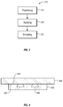
- FIG. 3 is a chart of a method for joining a non-weldable material and a weldable material, in accordance with at least one embodiment described herein;
- FIG. 4 is a schematic cross-sectional side view of a first workpiece positioned adjacent a second workpiece having recesses therein, in accordance with at least one embodiment described herein;
- FIG. 5 is a schematic cross-sectional side view of FSW tool applied to a surface of a workpiece of a weldable material, in accordance with at least one embodiment described herein;
- FIG. 6 is a schematic cross-sectional side view of a plasticized region of a first workpiece extruded into a recess of a second workpiece, in accordance with at least one embodiment described herein;
- FIG. 7 is a chart of a method for joining a non-weldable material to a weldable material to be affixed to a body, in accordance with at least one embodiment described herein;
- FIG. 8 is a schematic cross-sectional side view of a joined assembly positioned adjacent to a body, in accordance with at least one embodiment described herein;
- FIG. 9 is a schematic cross-sectional side view of a joined assembly welded to a body, in accordance with at least one embodiment described herein;
- FIG. 10 is a perspective view of a workpiece having recesses therein in accordance with at least one embodiment described herein;
- FIG. 11 is a bottom perspective view of a workpiece having intersecting recesses therein, in accordance with at least one embodiment described herein;
- FIG. 12 is a perspective view of a first workpiece having a cylindrical dovetail recess and a second workpiece extruded into the recess, in accordance with at least one embodiment described herein.
- One or more embodiments of the present disclosure may generally relate to the joining of a first material having a first strength and/or first ductility and a second material having a second strength and/or second ductility where the second strength is greater than the first strength and/or the second ductility is less than the first ductility.
- a tool steel workpiece may be joined to a tungsten carbide workpiece.
- the tool steel while having a high yield strength and low ductility, may still have a lower yield strength and greater ductility than the tungsten carbide.
- Tungsten carbide may be functionally non-weldable due to its high hardness and brittleness and low ductility.
- an aluminum alloy workpiece may be joined to a tool steel workpiece.
- the aluminum alloy while having a high yield strength and low ductility compared to some materials, may still have a lower yield strength and greater ductility than the tool steel.
- the tool steel while weldable by some processes including friction stir welding (“FSW”), may require specialized equipment or conditions that may render the tool steel non-weldable for a particular application.
- FSW friction stir welding
- non-weldable should be understood to describe a material and/or workpiece that is non-weldable given the equipment or conditions used to weld another material.
- a first material may be weldable by a given FSW tool capable of a certain speed of rotation, force applied normal to a workpiece, force applied lateral to a workpiece (e.g., to move the FSW tip along a path), movement speed, or other operational parameters.
- a second material may not be weldable by the given FSW tool, although the second material may be weldable by other equipment and/or conditions. Therefore, one should understand that the present disclosure may allow a given FSW tool to join a weldable material to a non-weldable material or, in other words, to a material which the given FSW tool may be unable to weld.
- a non-weldable material may include tungsten carbide, silicon carbide, alumina, cubic boron nitride, polycrystalline diamond, boron carbide, boron carbon nitride, materials having a hardness greater than 40 gigapascals (GPa) when measured by the Vicker's hardness test, or combinations thereof.
- GPa gigapascals
- a non-weldable material may include steel, such as carbon steel (e.g., AISI 10XX, AISI 11XX, AISI 12XX, or AISI 15XX), manganese steel (e.g., AISI 13XX), nickel steel (e.g., AISI 23XX, or AISI 25XX), nickel-chromium steel (e.g., AISI 31XX, AISI 32XX, AISI 33XX, or AISI 34XX), molybdenum steel (e.g., AISI 40XX, or AISI 44XX), chromium-molybdenum steel (e.g., AISI 41XX), nickel-chromium-molybdenum steel (e.g., AISI 43XX, or AISI 47XX), nickel-molybdenum steel (e.g., AISI 46XX, or AISI 48XX), chromium steel, such as carbon
- a weldable material and/or a non-weldable material may be magnetic or non-magnetic.
- the weldable workpiece may be a magnetic material or a non-magnetic material and the non-weldable workpiece may be a magnetic material or a non-magnetic material.
- a first workpiece made of or including a weldable material may be in contact with a second workpiece made of or including a non-weldable material.
- One, both, or neither of the workpieces may be magnetic.
- a workpiece that is magnetic may, in some embodiments, magnetize the adjacent workpiece.
- FIG. 1 depicts a schematic representation of a non-weldable workpiece 102 and a weldable workpiece 104 joined by mechanically interlocking the non-weldable workpiece 102 and a weldable workpiece 104 .
- the non-weldable workpiece 102 and weldable workpiece 104 may be oriented such that the non-weldable workpiece 102 may overlay at least a portion of a surface of the weldable workpiece 104 and form a friction stir welded (“FSW”) assembly 100 .
- FSW assembly 100 may be considered to be friction stir welded, although the material of the non-weldable workpiece 102 and weldable workpiece 104 does not combine.
- the non-weldable workpiece 102 may have a higher hardness than the weldable workpiece 104 .
- the non-weldable workpiece 102 may provide a more durable and/or wear resistant surface than the weldable workpiece 104 to which the non-weldable workpiece 102 is connected.
- the FSW assembly 100 may be used as a wear-resistant pad in high abrasion applications.
- the non-weldable workpiece 102 may be connected to the weldable workpiece 104 by a mechanical interlock.
- the non-weldable workpiece 102 may include one or more recesses 106 into which one of one or more extrusions 108 of the weldable workpiece 104 may be located.
- the recess 106 and extrusion 108 may be configured to complimentarily mate with one another.
- the recess 106 and extrusion 108 may have unequal dimensions.
- the recess 106 and extrusion 108 may be configured to limit movement of the non-weldable workpiece 102 and weldable workpiece 104 relative to one another to a range of positions (e.g., the recess 106 and extrusion 108 may allow some movement within the range).
- the recess 106 and extrusion 108 may substantially prevent movement of the non-weldable workpiece 102 and the weldable workpiece 104 relative to one another.
- FIG. 2 illustrates an embodiment of a downhole tool 210 for drilling applications including one or more FSW assemblies 200 having a non-weldable workpiece 202 welded thereto.
- the downhole tool 210 may be or be part of a drill string including one or more tubulars and a bottomhole assembly.
- the tubular may include a number of components such as segmented drill pipe, coiled tubing, drill collars, transition pipe (e.g., HEVI-WATE® drill pipe), drill pipe, or similar components.
- the tubular may transmit torque and/or longitudinal force through the primary wellbore to the bottomhole assembly.
- the bottomhole assembly may include a bit configured to remove material from the formation and/or to drill a lateral borehole extending from the primary wellbore.
- the downhole tool 210 may be used in a cased or openhole wellbore during drilling operations. The rotation of the drill string relative to the surrounding wellbore may result in abrasion or compression of parts of the downhole tool 210 as the downhole tool 210 rotates. Therefore, an FSW assembly 200 may increase the operational lifetime of a downhole tool 210 .
- the FSW assembly 200 may include a weldable workpiece 204 adjacent a body 212 of the downhole tool 210 .
- the body 212 may be made of or include a material to which the weldable workpiece 204 may be connected.
- the body 212 may be made of or include a weldable material that may be the same material as or a different material from a material in the weldable workpiece 204 .
- the weldable workpiece 204 may, therefore, be connected to the body 212 be any appropriate method including, but not limited to, FSW, TIG welding, MIG welding, shielded metal arc welding, flux-cored arc welding, brazing, threaded pins, other connection methods, or combinations thereof.
- the downhole tool 210 may have a body longitudinal axis 211 along a length of the body 212 .
- the body longitudinal axis 211 may be the rotational axis of the downhole tool 210 .
- the FSW assembly 200 may have an assembly centerline 213 .
- the assembly centerline 213 may be a centerline that extends through a length of the FSW assembly 200 , as shown in FIG. 2 .
- the assembly centerline 213 may be at least partially defined by the orientation of the non-weldable workpiece 202 .
- an FSW assembly 200 may include a non-weldable workpiece 202 that may have different dimensions and/or aspect ratio from a weldable workpiece 204 .
- the weldable workpiece 204 may be square and the non-weldable workpiece 202 may have a length and a width that have a ratio of 3.0.
- the FSW assembly 200 may include a plurality of non-weldable workpieces 202 affixed to the weldable workpiece 204 .
- the assembly centerline 213 may be defined by a line that passes through a centerpoint of at least two of the plurality of non-weldable workpieces 202 .
- the assembly centerline 213 may be substantially parallel to the body longitudinal axis 211 .
- the assembly centerline 213 and body longitudinal axis 211 may be non-parallel, e.g. helical relative to the body longitudinal axis 211 , and oriented at an angle relative to one another having upper and to lower values including any of 30°, 35°, 40°, 45°, 50°, 55°, 60°, 65°, 70°, 75°, 80°, 85°, less than 90°, or any value therebetween.
- the assembly centerline 213 and body longitudinal axis 211 may be oriented at an angle relative to one another between 40° and 65°.
- the assembly centerline 213 and body longitudinal axis 211 may be oriented at an angle relative to one another between 80° and less than 90°. In yet another example, the assembly centerline 213 and body longitudinal axis 211 may be oriented at an angle relative to one another of 60°.
- the FSW assembly 200 can be raised up to three times a diameter of the downhole tool 210 . In other embodiments, the FSW assembly 200 can be raised an amount in a range having values including any of 0.5, 1.0, 1.5, 2.0, 2.5, 3.0, or any value therebetween times the diameter of the downhole tool 210 . For example, the FSW assembly 200 can be raised an amount between 0.5 and 2.0 times the diameter of the downhole tool 210 . In other examples, the FSW assembly 200 can be raised an amount between 1.0 and 1.5 times the diameter of the downhole tool 210 .
- the FSW assembly 200 may also vary in thickness.
- the FSW assembly 200 may be tapered at at least one edge of the FSW assembly 200 .
- the thickness of the weldable workpiece 204 may be varied and/or the thickness of the non-weldable workpiece 202 may be varied.
- the thickness of the weldable workpiece 204 may be greatest in a center of the weldable workpiece 204 .
- the thickness of the weldable workpiece 204 may be greatest at an edge and may have a taper to an opposing edge (e.g., a ramp-like structure).
- the thickness of the non-weldable workpiece 202 may be greatest in a center of the non-weldable workpiece 202 .
- the thickness of the non-weldable workpiece 202 may be greatest at an edge and may have a taper to an opposing edge (e.g., a ramp-like structure). In yet further examples, the thickness of the non-weldable workpiece 202 and/or weldable workpiece 204 may be constant across the area of the FSW assembly 200 .
- the width of the FSW assembly 200 could be about 1 ⁇ 6 to 1 ⁇ 4 of the circumference of the downhole tool.
- the circumference of the downhole tool 210 may include one or more FSW assemblies 200 that account for a portion of the circumference of the downhole tool.
- the downhole tool 210 may include one or more FSW assemblies 200 that may account for 25%, 30%, 35%, 40%, 45%, 50%, 55%, 60%, 65%, 70%, 75%, 80%, 85%, 90%, 95%, or 100% of the circumference of the downhole tool 210 .
- the one or more FSW assemblies 200 may count for between 30% and 90% of the circumference of the downhole tool 210 .
- the one or more FSW assemblies 200 may count for between 40% and 80% of the circumference of the downhole tool 210 . In yet other examples, the one or more FSW assemblies 200 may count for between 45% and 65% of the circumference of the downhole tool 210 .
- a method 314 for joining a non-weldable workpiece to a weldable workpiece is shown in FIG. 3 .
- the method 314 may include positioning 316 a non-weldable workpiece adjacent a weldable workpiece and applying 318 force and heat to the weldable workpiece to plasticize and mobilize at least a portion of weldable workpiece.
- the heat applied to the weldable workpiece may be or include heat generated by friction between a FSW tool and the weldable workpiece.
- the heat applied to the weldable workpiece may be or include heat generated by an external heater, such as a laser, torch, or other heat source.
- Applying 318 force and heat to the weldable workpiece may assist in extruding 320 at least a portion of the weldable workpiece into a recess in the non-weldable workpiece to mechanically lock the weldable workpiece to the non-weldable workpiece and form an FSW assembly.
- FIG. 4 depicts another embodiment of a non-weldable workpiece 402 positioned adjacent a weldable workpiece 404 .
- the non-weldable workpiece 402 may contact the weldable workpiece 404 along a connection surface 422 of the non-weldable workpiece 402 having one or more recesses 406 therein.
- the connection surface 422 of the non-weldable workpiece 402 may abut an extrusion surface 424 of the weldable workpiece 404 .
- FIG. 5 depicts a schematic representation of a FSW tool 526 having a FSW tip 528 adjacent a welding surface 530 of a weldable workpiece 504 .
- the FSW tool 526 may be able to rotate the FSW tip 528 at sufficient speed and while applying surface force to the FSW tip 528 to plunge the FSW tip 528 into the weldable workpiece 504 .
- the weldable workpiece may be made of or include a high melting temperature metal alloy and the FSW tool may rotate the FSW tip 528 at a rate in a range having upper and lower values including 50 revolutions per minute (“RPM”), 100 RPM, 150 RPM, 200 RPM, 250 RPM, 300 RPM, 350 RPM, 400 RPM, 450 RPM, 500 RPM, 600 RPM, 700 RPM, 800 RPM, 900 RPM, 1000 RPM, or any value therebetween.
- RPM revolutions per minute
- the FSW tool may apply a force to the weldable workpiece in a range having upper and lower values including 4 kilonewtons (“kN”), 6 kN, 8 kN, 10 kN, 20 kN, 30 kN, 40 kN, 50 kN, 60 kN, 70 kN, 80 kN, 90 kN, 100 kN, or any value therebetween.
- kN kilonewtons
- the weldable workpiece 504 may be made of or include tool steel.
- the FSW tool 526 may be positioned adjacent the welding surface 530 and aligned with a recess 506 in a non-weldable workpiece 502 .
- aligned with should be understood to include positioned adjacent a point on the welding surface 530 nearest the recess 506 (as shown in FIG. 5 ), as well as positioned adjacent a point on the welding surface 530 such that an axis of rotation of the FSW tool 526 and/or FSW tip 528 may intersect at least part of a recess 506 in the non-weldable workpiece 502 .
- a FSW tool 526 may be positioned at an angle with the welding surface 530 that is less than 90° (e.g., a 45° angle).
- the FSW tool 526 may be moved relative to the welding surface 530 such that the FSW tool 526 may apply a force to the welding surface 530 that is coaxial with the axis of rotation of the FSW tool 526 and/or FSW tip 528 .
- a path of movement of the FSW tool 526 may thereby urge the plasticized portion of the weldable workpiece 504 toward the recess 506 in the non-weldable workpiece 502 .
- FIG. 6 depicts an embodiment of a non-weldable workpiece 602 and a weldable workpiece 604 joined by an extrusion 608 that is at least partially located in the recess 606 .
- the extrusion may be extruded from the weldable workpiece 604 by a FSW tip 628 plunged into the weldable workpiece 604 by a FSW tool 626 .
- Heat and force applied by the FSW tool 626 to the weldable workpiece 604 may create a friction stirred zone 631 .
- the friction stirred zone 631 may exhibit an altered microstructure relative to the original microstructure of the weldable workpiece 604 .
- the friction stirred zone 631 may exhibit an unaltered chemical composition relative to the original chemical composition of the weldable workpiece 604 .
- a method 732 for joining a non-weldable workpiece to an outer surface of a main body may include at least part of a method 714 similar to or the same as the method 314 depicted in FIG. 3 .
- the method 732 may include positioning 716 a non-weldable workpiece adjacent a weldable workpiece and applying 718 a force and heat to the weldable workpiece to plasticize and mobilize at least a portion of weldable workpiece.
- the heat applied to the weldable workpiece may be or include heat generated by friction between a FSW tool and the weldable workpiece.
- the heat applied to the weldable workpiece may be or include heat generated by an external heater, such as a laser, torch, or other heat source. Applying 718 a force and heat to the weldable workpiece may assist in extruding 720 at least a portion of the weldable workpiece into a recess in the non-weldable workpiece to mechanically lock the weldable workpiece to the non-weldable workpiece and form an FSW assembly.
- the method 732 may include positioning 734 the FSW assembly adjacent a body, such as the body of a downhole tool, and welding 736 the FSW assembly to the body.
- the method 732 may include positioning 734 a FSW assembly including a carbide non-weldable workpiece and welding 736 the FSW assembly to a body made of or including a high melting temperature metal.
- the body may be the body of a downhole tool.
- the body may be the body of a tubular in a drill string.
- the FSW assembly may be a wear pad (for example, a stabilizer pad) and may be welded to a component of a bottomhole assembly.
- the wear pad may be welded to a downhole tool such a tubular, including segmented drill pipe, coiled tubing, drill collars, transition pipe (e.g., HEVI-WATE drill pipe), and drill pipe; or other downhole tools, including a bit, a cutter, bit drive assembly, motor, MWD, LWD, communications module, anchor, stabilizer, underreamer, milling tool, jarring device, and crossovers.
- a downhole tool such as tubular, including segmented drill pipe, coiled tubing, drill collars, transition pipe (e.g., HEVI-WATE drill pipe), and drill pipe; or other downhole tools, including a bit, a cutter, bit drive assembly, motor, MWD, LWD, communications module, anchor, stabilizer, underreamer, milling tool, jarring device, and crossovers.
- FIG. 8 depicts an embodiment of an FSW assembly 800 having a non-weldable workpiece 802 connected to a weldable workpiece 804 .
- the outer surfaces of the FSW assembly 800 may be a wear surface 838 adjacent the non-weldable workpiece 802 and a welding surface 840 .
- the welding surface 840 may be positioned adjacent an outer surface 812 of a body 810 .
- the body 801 as described in relation to FIG. 7 , may be the body of a downhole tool.
- the body 810 may be the body of a tubular in a drill string.
- the body 810 may be or be part of a digging tool on a piece of heavy equipment.
- the body 810 may be or be part of an asphalt zipper or similar demolition tool.
- the FSW assembly 900 as shown in FIG. 9 , may be welded, brazed, bolted, screwed, locked, otherwise fixed to a body 910 or a combination thereof.
- the welding surface 940 of the weldable workpiece 904 may be weldable to the outer surface 912 of the body 910 .
- the wear surface 938 of the FSW assembly 900 may be thereby affixed to the outer surface 912 of the body 910 with the weldable workpiece 904 functioning similarly to a substrate.
- the wear surface 938 .
- the non-weldable workpiece 902 may be made of or include a material that is harder than the body 910 , effectively increasing the wear resistance and/or operational lifetime of the body 910 .
- the non-weldable workpiece 902 may include tungsten carbide, cubic boron nitride, polycrystalline diamond, boron carbide, boron carbon nitride, other materials having a hardness greater than 40 gigapascals (GPa) when measured by the Vicker's hardness test, or combinations thereof.
- the body 910 may include steel, titanium alloys, nickel superalloys, other metal high melting temperature alloys, or combinations thereof.
- steel, titanium alloys, nickel superalloys, other metal high melting temperature alloys, or combinations thereof may, in some embodiments, be non-weldable materials when paired with softer materials, such as aluminum.
- softer materials such as aluminum.
- superhard materials such as tungsten carbide, cubic boron nitride, polycrystalline diamond, boron carbide, boron carbon nitride, other materials having a hardness greater than 40 gigapascals (GPa)
- metals such as steel, titanium alloys, nickel superalloys, other metal high melting temperature alloys, or combinations thereof may be properly considered weldable materials according to the present disclosure.
- equipment capable of welding aluminum may be unable to weld a nickel superalloy
- equipment capable of welding a nickel superalloy may be unable to weld tungsten carbide.
- a recess 1006 in a non-weldable workpiece 1002 may be formed in a variety of ways and a variety of geometries.
- a carbide such as tungsten carbide may be formed by cold-pressing a powder including tungsten carbide crystals and cobalt with a binding agent.
- the cold-pressed material is a “green” state, which may be formed to a desired shape.
- the green state may be relatively soft and allow the material to be manipulated, molded, ground, otherwise machined, or combinations thereof.
- the non-weldable workpiece 1002 in a green state may be then be subjected to a high temperature sintering process, which may or may not include high pressures.
- the sintering process may alter the dimensions of the carbide component; for example, reducing the size of the non-weldable workpiece 1002 .
- One or more recesses may be formed in a non-weldable workpiece 1002 during the green state of manufacturing or may be ground into the non-weldable workpiece 1002 after sintering.
- one or more recesses 1006 may be machined in the non-weldable workpiece 1002 .
- a recess 1006 may have a first width 1042 and a second width 1044 .
- the first width 1042 may be proximate a connection surface 1022 of the non-weldable workpiece 1002 .
- the second width 1044 may be farther from the connection surface 1022 than the first width.
- the second width 1044 may be greater than the first width 1042 , creating a dovetail shape when viewed in cross-section, as shown in FIG. 10 .
- the dovetail shape may allow an extrusion, such as extrusion 608 shown in FIG. 6 , to mechanically lock within the recess 1006 .
- At least part of a lateral side 1050 of the recess 1006 between the first width 1042 and the second width 1044 may form a first angle 1046 with the connection surface 1022 .
- the recess 1006 may have straight sides 1050 .
- the recess 1006 may have a side 1050 with at least a portion of the side 1050 being curved.
- the recess 1006 may have a second angle 1048 that opposes the first angle 1046 .
- the second angle 1048 may be equal to the first angle 1046 .
- the second angle 1048 may be greater than or less than the first angle 1046 .
- the first angle 1046 and/or second angle 1048 may be less than 90°.
- a first angle 1046 and/or second angle 1048 being less than 90° may allow a first width 1042 that is less than a second width 1044 .
- the first angle 1046 and/or second angle 1048 may be within a range having upper and lower values including any of 50°, 55°, 60°, 65°, 70°, 75°, 80°, 85°, less than 90°, or any value therebetween.
- the first angle 1046 and/or second angle 1048 may be between 60° and 85°.
- the first angle 1046 and/or second angle 1048 may be 80°.
- Extruding material from a weldable workpiece may apply a pressure to the sides 1050 of the recess 1006 .
- Lower values for the first angle 1046 and/or second angle 1048 may allow extruded material to apply a force between one or more sides 1050 and a base 1052 of the recess 1006 .
- a force between one or more sides 1050 and the base 1052 of the recess 1006 may weaken the non-weldable workpiece 1002 .
- One or more recesses 1006 in the non-weldable workpiece 1002 may be substantially straight along the length of the non-weldable workpiece. In other embodiments, a recess 1006 may be curved relative to the length of the non-weldable workpiece. A recess 1006 having a first width 1042 that is smaller than a second width 1044 may limit or, in some cases, prevent movement of weldable workpiece normal to the connection surface 1022 . As shown in FIG. 11 , one or more recesses 1106 may be oriented at a recess angle 1154 with respect to one another with one another. FIG. 11 depicts a plurality of recesses 1106 intersecting at the recess angle 1154 . In other embodiments, a non-weldable workpiece 1102 may have a plurality of non-intersecting recesses 1106 at one or more recess angles 1154 .
- FIG. 12 depicts an embodiment of a FSW assembly 1200 including a recess 1206 that is substantially rotationally symmetrical.
- the recess 1206 may have a dovetail shape similar to that described in relation to FIG. 10 .
- the recess 1206 may have a first width 1242 proximate a weldable workpiece 1204 and a second width 1244 within the non-weldable workpiece 1202 .
- the first width 1242 and second width 1244 may be a first diameter and second diameter.
- the recess 1206 may be a closed recess such as a recess 1206 that is round, square, rectangular, elliptical, another regular shape, another irregular shape, or any other shape that does not intersect a lateral side 1256 of the non-weldable workpiece 1206 .
- An extrusion 1208 may be extruded into the closed recess 1206 and mechanically lock the non-weldable workpiece 1206 to a weldable workpiece.
- the weldable workpiece may be an intermediate workpiece that may be configured to be subsequently welded to a body or other surface of a downhole tool.
- the weldable workpiece may be part of a body or other surface of a downhole tool and/or the non-weldable workpiece may be part of a body or other surface of a downhole tool.
- a portion of a weldable first tubular may be positioned concentrically surrounding a portion of a non-weldable second tubular. Part of the weldable first tubular may be plasticized using a FSW tool and extruded into a recess in the non-weldable second member, mechanically joining the first tubular with the second tubular.
- a portion of a non-weldable first tubular may be positioned concentrically surrounding a portion of a weldable second tubular.
- Part of the weldable second tubular may be plasticized using a FSW tool and extruded into a recess in the non-weldable second member, mechanically joining the first tubular with the second tubular.
- a stated value should therefore be interpreted broadly enough to encompass values that are at least close enough to the stated value to perform a desired function or achieve a desired result.
- the stated values include at least to the variation to be expected in a suitable manufacturing or production process, and may include values that are within 5%, within 1%, within 0.1%, or within 0.01% of a stated value.
- any references to “up” and “down” or “above” or “below” are merely descriptive of the relative position or movement of the related elements.
Landscapes
- Engineering & Computer Science (AREA)
- Mechanical Engineering (AREA)
- Life Sciences & Earth Sciences (AREA)
- Geology (AREA)
- Mining & Mineral Resources (AREA)
- General Engineering & Computer Science (AREA)
- Physics & Mathematics (AREA)
- Environmental & Geological Engineering (AREA)
- Fluid Mechanics (AREA)
- General Life Sciences & Earth Sciences (AREA)
- Geochemistry & Mineralogy (AREA)
- Pressure Welding/Diffusion-Bonding (AREA)
Abstract
Description
Claims (20)
Priority Applications (1)
| Application Number | Priority Date | Filing Date | Title |
|---|---|---|---|
| US15/324,866 US10695861B2 (en) | 2014-07-10 | 2015-07-09 | Friction stir extrusion of nonweldable materials for downhole tools |
Applications Claiming Priority (5)
| Application Number | Priority Date | Filing Date | Title |
|---|---|---|---|
| US201462026166P | 2014-07-10 | 2014-07-10 | |
| US201462023166P | 2014-07-10 | 2014-07-10 | |
| US201462084432P | 2014-11-25 | 2014-11-25 | |
| PCT/US2015/039787 WO2016007773A1 (en) | 2014-07-10 | 2015-07-09 | Friction stir extrusion of nonweldable materials for downhole tools |
| US15/324,866 US10695861B2 (en) | 2014-07-10 | 2015-07-09 | Friction stir extrusion of nonweldable materials for downhole tools |
Publications (2)
| Publication Number | Publication Date |
|---|---|
| US20170216961A1 US20170216961A1 (en) | 2017-08-03 |
| US10695861B2 true US10695861B2 (en) | 2020-06-30 |
Family
ID=59386125
Family Applications (1)
| Application Number | Title | Priority Date | Filing Date |
|---|---|---|---|
| US15/324,866 Expired - Fee Related US10695861B2 (en) | 2014-07-10 | 2015-07-09 | Friction stir extrusion of nonweldable materials for downhole tools |
Country Status (1)
| Country | Link |
|---|---|
| US (1) | US10695861B2 (en) |
Families Citing this family (29)
| Publication number | Priority date | Publication date | Assignee | Title |
|---|---|---|---|---|
| US12365027B2 (en) | 2013-03-22 | 2025-07-22 | Battelle Memorial Institute | High speed shear-assisted extrusion |
| US11045851B2 (en) | 2013-03-22 | 2021-06-29 | Battelle Memorial Institute | Method for Forming Hollow Profile Non-Circular Extrusions Using Shear Assisted Processing and Extrusion (ShAPE) |
| US12551946B2 (en) | 2013-03-22 | 2026-02-17 | Battelle Memorial Institute | Devices and methods for performing shear-assisted extrusion and extrusion processes |
| US12403516B2 (en) | 2013-03-22 | 2025-09-02 | Battelle Memorial Institute | Shape processes, feedstock materials, conductive materials and/or assemblies |
| US20210379638A1 (en) | 2013-03-22 | 2021-12-09 | Battelle Memorial Institute | Devices and Methods for Performing Shear-Assisted Extrusion and Extrusion Processes |
| US12186791B2 (en) | 2013-03-22 | 2025-01-07 | Battelle Memorial Institute | Devices and methods for performing shear-assisted extrusion and extrusion processes |
| US11383280B2 (en) | 2013-03-22 | 2022-07-12 | Battelle Memorial Institute | Devices and methods for performing shear-assisted extrusion, extrusion feedstocks, extrusion processes, and methods for preparing metal sheets |
| US10695811B2 (en) | 2013-03-22 | 2020-06-30 | Battelle Memorial Institute | Functionally graded coatings and claddings |
| WO2017066080A1 (en) * | 2015-10-12 | 2017-04-20 | Schlumberger Technology Corporation | System and methodology for joining components |
| US20200016687A1 (en) | 2016-09-12 | 2020-01-16 | Battelle Memorial Institute | Methods and Devices for Connecting Two Dissimilar Materials |
| US20180073532A1 (en) | 2016-09-12 | 2018-03-15 | Battelle Memorial Institute | System and process for joining dissimilar materials and solid-state interlocking joint with intermetallic interface formed thereby |
| US10799980B2 (en) | 2016-10-06 | 2020-10-13 | Mazak Corporation | Compressible friction stir welding tool for conventional machining equipment |
| US10415320B2 (en) * | 2017-06-26 | 2019-09-17 | Baker Hughes, A Ge Company, Llc | Earth-boring tools including replaceable hardfacing pads and related methods |
| US11130192B2 (en) | 2017-08-30 | 2021-09-28 | Mazak Corporation | Instrumented tool handler for friction stir welding |
| EP3450082B1 (en) | 2017-08-31 | 2020-12-16 | Mazak Corporation | Devices and methods for increased wear resistance during low temperature friction stir processing |
| JP2019058933A (en) | 2017-09-27 | 2019-04-18 | 日本軽金属株式会社 | Manufacturing method of liquid-cooled jacket |
| JP2019058934A (en) | 2017-09-27 | 2019-04-18 | 日本軽金属株式会社 | Manufacturing method of liquid-cooled jacket |
| JP7003589B2 (en) * | 2017-11-15 | 2022-01-20 | 日本軽金属株式会社 | Joining method |
| EP3486021B1 (en) | 2017-11-21 | 2023-05-03 | Megastir Technologies LLC | Friction stir processing tool with radial protrusion |
| JP6769427B2 (en) | 2017-12-18 | 2020-10-14 | 日本軽金属株式会社 | How to manufacture a liquid-cooled jacket |
| JP6927128B2 (en) | 2018-04-02 | 2021-08-25 | 日本軽金属株式会社 | How to manufacture a liquid-cooled jacket |
| JP2019181473A (en) | 2018-04-02 | 2019-10-24 | 日本軽金属株式会社 | Liquid-cooled jacket manufacturing method |
| US11440133B2 (en) | 2018-05-04 | 2022-09-13 | Mazak Corporation | Low-cost friction stir processing tool |
| CN110465737B (en) | 2018-05-09 | 2023-11-21 | 杨百翰大学 | Systems and methods for friction drill bit engagement |
| JP7070389B2 (en) | 2018-12-19 | 2022-05-18 | 日本軽金属株式会社 | Joining method |
| US11549532B1 (en) | 2019-09-06 | 2023-01-10 | Battelle Memorial Institute | Assemblies, riveted assemblies, methods for affixing substrates, and methods for mixing materials to form a metallurgical bond |
| US12116844B2 (en) * | 2019-11-19 | 2024-10-15 | Schlumberger Technology Corporation | Tiling for downhole tool |
| US11919061B2 (en) | 2021-09-15 | 2024-03-05 | Battelle Memorial Institute | Shear-assisted extrusion assemblies and methods |
| US12502701B2 (en) | 2022-07-05 | 2025-12-23 | Battelle Memorial Institute | Shear assisted extrusion apparatus, tools, and methods |
Citations (56)
| Publication number | Priority date | Publication date | Assignee | Title |
|---|---|---|---|---|
| US3660889A (en) | 1968-11-06 | 1972-05-09 | Lion Oil Tool Holdings Interna | Method of making a wear blade for an oil drilling tool |
| US4156374A (en) | 1978-03-20 | 1979-05-29 | Shwayder Warren M | Pre-formed wear pads for drill stabilizers |
| US5806615A (en) * | 1995-04-07 | 1998-09-15 | Drilltech Services (North Sea), Ltd. | Apparatus for use in a wellbore |
| US20020162620A1 (en) | 2001-05-01 | 2002-11-07 | Jeffrey Liaw | Adhering sealing member to metal with weld heat |
| US20030075584A1 (en) | 2001-10-04 | 2003-04-24 | Sarik Daniel J. | Method and apparatus for friction stir welding |
| US6648206B2 (en) | 2000-05-08 | 2003-11-18 | Tracey W. Nelson | Friction stir welding using a superabrasive tool |
| US20040057782A1 (en) * | 2002-09-20 | 2004-03-25 | Kazutaka Okamoto | Method of joining metallic materials |
| US6732901B2 (en) | 2001-06-12 | 2004-05-11 | Brigham Young University Technology Transfer Office | Anvil for friction stir welding high temperature materials |
| US20040149807A1 (en) * | 2003-01-30 | 2004-08-05 | Christoph Schilling | Method and apparatus for joining at least two work pieces by friction stir welding |
| US20050051602A1 (en) | 2003-05-13 | 2005-03-10 | Babb Jonathan Allyn | Control system for friction stir welding of metal matrix composites, ferrous alloys, non-ferrous alloys, and superalloys |
| US20050142005A1 (en) | 2003-12-08 | 2005-06-30 | Traylor Leland B. | Submersible well pump with improved diaphragm |
| US20060032891A1 (en) | 2004-03-24 | 2006-02-16 | Flak Richard A | Solid state processing of materials through friction stir processing and friction stir mixing |
| US20060032333A1 (en) | 2004-03-24 | 2006-02-16 | Steel Russell J | Solid state processing of industrial blades, edges and cutting elements |
| US20060049234A1 (en) | 2004-05-21 | 2006-03-09 | Flak Richard A | Friction stirring and its application to drill bits, oil field and mining tools, and components in other industrial applications |
| US20060157531A1 (en) | 2004-12-17 | 2006-07-20 | Packer Scott M | Single body friction stir welding tool for high melting temperature materials |
| US20060175382A1 (en) | 2003-11-10 | 2006-08-10 | Packer Scott M | Tool geometries for friction stir spot welding of high melting temperature alloys |
| US7156171B2 (en) * | 2000-09-06 | 2007-01-02 | Casetech International, Inc. | Dual diameter and rotating centralizer/sub |
| US7225968B2 (en) | 2003-08-04 | 2007-06-05 | Sii Megadiamond, Inc. | Crack repair using friction stir welding on materials including metal matrix composites, ferrous alloys, non-ferrous alloys, and superalloys |
| US20070187465A1 (en) | 2006-01-31 | 2007-08-16 | Eyre Ronald K | Thermally enhanced tool for friction stirring |
| US7270257B2 (en) | 2003-01-30 | 2007-09-18 | Sii Megadiamond, Inc. | Out-of-position friction stir welding of high melting temperature alloys |
| US20080206116A1 (en) | 2007-02-28 | 2008-08-28 | Akihiro Satou | Friction stir welding method for laminated member and hydrogen reactor |
| JP2009022974A (en) | 2007-07-19 | 2009-02-05 | Kosei Aluminum Co Ltd | Friction welding method for inner surface of pipe member |
| US7494040B2 (en) | 2003-09-25 | 2009-02-24 | Sii Megadiamond, Inc. | Friction stir welding improvements for metal matrix composites, ferrous alloys, non-ferrous alloys, and superalloys using a superabrasive tool |
| US7530486B2 (en) | 2003-05-05 | 2009-05-12 | Sii Megadiamond, Inc. | Applications of friction stir welding using a superabrasive tool |
| US20090294514A1 (en) | 2004-09-27 | 2009-12-03 | Sii Megadiamond, Inc. | Friction stir welding improvements for metal matrix composites, ferrous alloys, non-ferrous alloys, and superalloys using a superabrasive tool |
| US7651018B2 (en) | 2004-10-05 | 2010-01-26 | Sii Megadiamond | Expandable mandrel for use in friction stir welding |
| US20100071961A1 (en) | 2004-05-21 | 2010-03-25 | Smith International, Inc. | Bit leg outer surface processing using friction stir welding (fsw) |
| US20100078224A1 (en) | 2004-05-21 | 2010-04-01 | Smith International, Inc. | Ball hole welding using the friction stir welding (fsw) process |
| US20100167083A1 (en) * | 2008-12-26 | 2010-07-01 | Hitachi, Ltd. | Composite material and producing mehtod thereof |
| US7753252B2 (en) | 2005-05-05 | 2010-07-13 | Smith International | Method for construction of pressure vessels with a liner using friction stirring processes |
| US7845545B2 (en) | 2006-06-13 | 2010-12-07 | Brigham Young University | Three-body joining using friction stir processing techniques |
| US7909231B2 (en) | 2008-08-11 | 2011-03-22 | Megastir Technologies Llc | Method for using modifiable tool control parameters to control the temperature of the tool during friction stir welding |
| US20110127311A1 (en) | 2009-11-02 | 2011-06-02 | Jeremy Peterson | Out of position friction stir welding of casing and small diameter tubing or pipe |
| CN102120287A (en) | 2010-12-16 | 2011-07-13 | 西安交通大学 | Embedded stirring and rubbing slit welding method |
| US7992759B2 (en) | 2005-06-10 | 2011-08-09 | Megastir Technologies, LLC | Two spiral stepped friction stir welding tool |
| US8056797B2 (en) | 2005-10-05 | 2011-11-15 | Megastir Technologies | Expandable mandrel for use in friction stir welding |
| US20120055977A1 (en) | 2010-08-02 | 2012-03-08 | Steel Russell J | System for using high rotary speed for minimizing the load during friction stir welding |
| US8157154B2 (en) | 2007-06-13 | 2012-04-17 | Brigham Young University | Three-body joining using friction stir processing techniques |
| US8241556B2 (en) | 2008-08-11 | 2012-08-14 | Megastir Technologies Llc | Rotary holding device for gripping tool material at elevated temperatures through multiple collar assembly |
| US8317080B2 (en) | 2010-08-02 | 2012-11-27 | Megastir Technologies Llc | Methods to fabricate fully enclosed hollow structures using friction stir welding |
| US8469256B2 (en) | 2008-08-11 | 2013-06-25 | Megastir Technologies Llc | Method for using a non-linear control parameter ramp profile to approach a temperature set point of a tool or weld that prevents temperature overshoot during friction stir welding |
| US20130206818A1 (en) | 2011-12-30 | 2013-08-15 | Megastir Technologies Llc | System and method for holding materials having arcuate surfaces in place for friction stir welding or processing |
| US20130228612A1 (en) | 2012-03-02 | 2013-09-05 | Megastir Technologies Llc | Friction bit joining of materials |
| US8550326B2 (en) | 2005-10-05 | 2013-10-08 | Megastir Technologies Llc | Expandable mandrel for use in friction stir welding |
| US20130299561A1 (en) | 2012-05-14 | 2013-11-14 | Paul T. Higgins | Friction stir joining of curved surfaces |
| US20140034215A1 (en) | 2012-07-26 | 2014-02-06 | Tata Technologies Pte Ltd | Apparatus and process for joining homogeneous and heterogeneous materials with customized interface properties |
| US20140151438A1 (en) | 2012-05-14 | 2014-06-05 | Rodney Dale Fleck | Apparatus to join tubulars using friction stir joining |
| US8910851B2 (en) | 2011-09-20 | 2014-12-16 | Megastir Technologies Llc | Material surface modification using friction stir welding hybrid process |
| US9061371B2 (en) | 2012-05-14 | 2015-06-23 | Megastir Technologies Llc | Disposable mandrel for friction stir joining |
| US20170197274A1 (en) | 2014-07-10 | 2017-07-13 | Megastir Technologies Llc | Mechanical flow joining of high melting temperature materials |
| US9764375B2 (en) | 2012-03-02 | 2017-09-19 | Brigham Young University | Friction bit joining of materials using a friction rivet |
| US20180073532A1 (en) * | 2016-09-12 | 2018-03-15 | Battelle Memorial Institute | System and process for joining dissimilar materials and solid-state interlocking joint with intermetallic interface formed thereby |
| US20180099349A1 (en) | 2016-10-06 | 2018-04-12 | Scott M. Packer | Method and apparatus for friction stir welding on conventional machining equipment |
| US20190061048A1 (en) | 2017-08-30 | 2019-02-28 | Megastir Technologies Llc | Instrumented tool handler for friction stir welding |
| US20190061046A1 (en) | 2017-08-31 | 2019-02-28 | Megastir Technologies Llc | Devices, systems, and methods for increased wear resistance during low temperature friction stir processing |
| US20190151982A1 (en) | 2017-11-21 | 2019-05-23 | Megastir Technologies Llc | Friction stir processing tool with radial protrusion |
-
2015
- 2015-07-09 US US15/324,866 patent/US10695861B2/en not_active Expired - Fee Related
Patent Citations (77)
| Publication number | Priority date | Publication date | Assignee | Title |
|---|---|---|---|---|
| US3660889A (en) | 1968-11-06 | 1972-05-09 | Lion Oil Tool Holdings Interna | Method of making a wear blade for an oil drilling tool |
| US4156374A (en) | 1978-03-20 | 1979-05-29 | Shwayder Warren M | Pre-formed wear pads for drill stabilizers |
| US5806615A (en) * | 1995-04-07 | 1998-09-15 | Drilltech Services (North Sea), Ltd. | Apparatus for use in a wellbore |
| US7124929B2 (en) | 2000-05-08 | 2006-10-24 | Sii Megadiamond, Inc. | Friction stir welding of metal matrix composites, ferrous alloys, non-ferrous alloys, and superalloys using a superabrasive tool |
| US7993575B2 (en) | 2000-05-08 | 2011-08-09 | Megastir Technologies, LLC | Friction stir welding using a superabrasive tool |
| US6648206B2 (en) | 2000-05-08 | 2003-11-18 | Tracey W. Nelson | Friction stir welding using a superabrasive tool |
| US7661572B2 (en) | 2000-05-08 | 2010-02-16 | Brigham Young University | Friction stir welding using a superabrasive tool |
| US7152776B2 (en) | 2000-05-08 | 2006-12-26 | Sii Megadiamond, Inc. | Friction stir welding using a superabrasive tool |
| US9061370B2 (en) | 2000-05-08 | 2015-06-23 | Brigham Young University | Friction stir welding using a superabrasive tool |
| US6779704B2 (en) | 2000-05-08 | 2004-08-24 | Tracy W. Nelson | Friction stir welding of metal matrix composites, ferrous alloys, non-ferrous alloys, and superalloys using a superabrasive tool |
| US20130062395A1 (en) | 2000-05-08 | 2013-03-14 | Brigham Young University | Friction stir welding using a superabrasive tool |
| US8302834B2 (en) | 2000-05-08 | 2012-11-06 | MegaStar Technologies LLC | Friction stir welding using a superabrasive tool |
| US7156171B2 (en) * | 2000-09-06 | 2007-01-02 | Casetech International, Inc. | Dual diameter and rotating centralizer/sub |
| US20020162620A1 (en) | 2001-05-01 | 2002-11-07 | Jeffrey Liaw | Adhering sealing member to metal with weld heat |
| US20050006439A1 (en) | 2001-06-12 | 2005-01-13 | Packer Scott M. | Anvil for friction stir welding high temperature materials |
| US7608296B2 (en) | 2001-06-12 | 2009-10-27 | Brigham Young University | Anvil for friction stir welding high temperature materials |
| US6732901B2 (en) | 2001-06-12 | 2004-05-11 | Brigham Young University Technology Transfer Office | Anvil for friction stir welding high temperature materials |
| US20030075584A1 (en) | 2001-10-04 | 2003-04-24 | Sarik Daniel J. | Method and apparatus for friction stir welding |
| US20040057782A1 (en) * | 2002-09-20 | 2004-03-25 | Kazutaka Okamoto | Method of joining metallic materials |
| US20080029578A1 (en) | 2003-01-30 | 2008-02-07 | Russell Steel | Out-of position friction stir welding of high melting temperature alloys |
| US20040149807A1 (en) * | 2003-01-30 | 2004-08-05 | Christoph Schilling | Method and apparatus for joining at least two work pieces by friction stir welding |
| US7270257B2 (en) | 2003-01-30 | 2007-09-18 | Sii Megadiamond, Inc. | Out-of-position friction stir welding of high melting temperature alloys |
| US7530486B2 (en) | 2003-05-05 | 2009-05-12 | Sii Megadiamond, Inc. | Applications of friction stir welding using a superabrasive tool |
| US20050051602A1 (en) | 2003-05-13 | 2005-03-10 | Babb Jonathan Allyn | Control system for friction stir welding of metal matrix composites, ferrous alloys, non-ferrous alloys, and superalloys |
| US7225968B2 (en) | 2003-08-04 | 2007-06-05 | Sii Megadiamond, Inc. | Crack repair using friction stir welding on materials including metal matrix composites, ferrous alloys, non-ferrous alloys, and superalloys |
| US7494040B2 (en) | 2003-09-25 | 2009-02-24 | Sii Megadiamond, Inc. | Friction stir welding improvements for metal matrix composites, ferrous alloys, non-ferrous alloys, and superalloys using a superabrasive tool |
| US20060175382A1 (en) | 2003-11-10 | 2006-08-10 | Packer Scott M | Tool geometries for friction stir spot welding of high melting temperature alloys |
| US20050142005A1 (en) | 2003-12-08 | 2005-06-30 | Traylor Leland B. | Submersible well pump with improved diaphragm |
| US20120227546A1 (en) | 2004-03-24 | 2012-09-13 | Diamond Blade, Llc | Solid state processing of hand-held knife blades to improve blade performance |
| US8186561B2 (en) | 2004-03-24 | 2012-05-29 | Megastir Technologies, LLC | Solid state processing of hand-held knife blades to improve blade performance |
| US20060032891A1 (en) | 2004-03-24 | 2006-02-16 | Flak Richard A | Solid state processing of materials through friction stir processing and friction stir mixing |
| US20060032333A1 (en) | 2004-03-24 | 2006-02-16 | Steel Russell J | Solid state processing of industrial blades, edges and cutting elements |
| US8955734B2 (en) | 2004-05-21 | 2015-02-17 | Smith International, Inc. | Ball hole welding using the friction stir welding (FSW) process |
| US20120273555A1 (en) | 2004-05-21 | 2012-11-01 | Megastir Technologies Llc | Friction stirring and its application to drill bits, oil field and mining tools, and components in other industrial applications |
| US20100071961A1 (en) | 2004-05-21 | 2010-03-25 | Smith International, Inc. | Bit leg outer surface processing using friction stir welding (fsw) |
| US20100078224A1 (en) | 2004-05-21 | 2010-04-01 | Smith International, Inc. | Ball hole welding using the friction stir welding (fsw) process |
| US20150258628A1 (en) | 2004-05-21 | 2015-09-17 | Smith International, Inc. | Friction stirring and its application to drill bits, oil field and mining tools, and components in other industrial applications |
| US20060049234A1 (en) | 2004-05-21 | 2006-03-09 | Flak Richard A | Friction stirring and its application to drill bits, oil field and mining tools, and components in other industrial applications |
| US20090294514A1 (en) | 2004-09-27 | 2009-12-03 | Sii Megadiamond, Inc. | Friction stir welding improvements for metal matrix composites, ferrous alloys, non-ferrous alloys, and superalloys using a superabrasive tool |
| US7651018B2 (en) | 2004-10-05 | 2010-01-26 | Sii Megadiamond | Expandable mandrel for use in friction stir welding |
| US20060157531A1 (en) | 2004-12-17 | 2006-07-20 | Packer Scott M | Single body friction stir welding tool for high melting temperature materials |
| US7753252B2 (en) | 2005-05-05 | 2010-07-13 | Smith International | Method for construction of pressure vessels with a liner using friction stirring processes |
| US7992759B2 (en) | 2005-06-10 | 2011-08-09 | Megastir Technologies, LLC | Two spiral stepped friction stir welding tool |
| US8550326B2 (en) | 2005-10-05 | 2013-10-08 | Megastir Technologies Llc | Expandable mandrel for use in friction stir welding |
| US8056797B2 (en) | 2005-10-05 | 2011-11-15 | Megastir Technologies | Expandable mandrel for use in friction stir welding |
| US20070187465A1 (en) | 2006-01-31 | 2007-08-16 | Eyre Ronald K | Thermally enhanced tool for friction stirring |
| US7845545B2 (en) | 2006-06-13 | 2010-12-07 | Brigham Young University | Three-body joining using friction stir processing techniques |
| US20080206116A1 (en) | 2007-02-28 | 2008-08-28 | Akihiro Satou | Friction stir welding method for laminated member and hydrogen reactor |
| US8157154B2 (en) | 2007-06-13 | 2012-04-17 | Brigham Young University | Three-body joining using friction stir processing techniques |
| JP2009022974A (en) | 2007-07-19 | 2009-02-05 | Kosei Aluminum Co Ltd | Friction welding method for inner surface of pipe member |
| US7909231B2 (en) | 2008-08-11 | 2011-03-22 | Megastir Technologies Llc | Method for using modifiable tool control parameters to control the temperature of the tool during friction stir welding |
| US8469256B2 (en) | 2008-08-11 | 2013-06-25 | Megastir Technologies Llc | Method for using a non-linear control parameter ramp profile to approach a temperature set point of a tool or weld that prevents temperature overshoot during friction stir welding |
| US8241556B2 (en) | 2008-08-11 | 2012-08-14 | Megastir Technologies Llc | Rotary holding device for gripping tool material at elevated temperatures through multiple collar assembly |
| US20110172802A1 (en) | 2008-08-11 | 2011-07-14 | Babb Jonathan A | Method for using modifiable tool control parameters to control the temperature of the tool during friction stir welding |
| US20100167083A1 (en) * | 2008-12-26 | 2010-07-01 | Hitachi, Ltd. | Composite material and producing mehtod thereof |
| US9242308B2 (en) | 2009-11-02 | 2016-01-26 | Megastir Technologies Llc | Out of position friction stir welding of casing and small diameter tubing or pipe |
| US20110127311A1 (en) | 2009-11-02 | 2011-06-02 | Jeremy Peterson | Out of position friction stir welding of casing and small diameter tubing or pipe |
| US8317080B2 (en) | 2010-08-02 | 2012-11-27 | Megastir Technologies Llc | Methods to fabricate fully enclosed hollow structures using friction stir welding |
| US20120055977A1 (en) | 2010-08-02 | 2012-03-08 | Steel Russell J | System for using high rotary speed for minimizing the load during friction stir welding |
| US8490855B2 (en) | 2010-08-02 | 2013-07-23 | Megastir Technologies Llc | Methods to fabricate fully enclosed hollow structures using friction stir welding |
| US20140008418A1 (en) | 2010-08-02 | 2014-01-09 | Megastir Technologies Llc | System for using high rotary speed for minimizing the load during friction stir welding |
| CN102120287A (en) | 2010-12-16 | 2011-07-13 | 西安交通大学 | Embedded stirring and rubbing slit welding method |
| US9352425B2 (en) | 2011-09-20 | 2016-05-31 | Megastir Technologies Llc | Material surface modification using friction stir welding hybrid process |
| US8910851B2 (en) | 2011-09-20 | 2014-12-16 | Megastir Technologies Llc | Material surface modification using friction stir welding hybrid process |
| US20130206818A1 (en) | 2011-12-30 | 2013-08-15 | Megastir Technologies Llc | System and method for holding materials having arcuate surfaces in place for friction stir welding or processing |
| US9764375B2 (en) | 2012-03-02 | 2017-09-19 | Brigham Young University | Friction bit joining of materials using a friction rivet |
| US20130228612A1 (en) | 2012-03-02 | 2013-09-05 | Megastir Technologies Llc | Friction bit joining of materials |
| US20140151438A1 (en) | 2012-05-14 | 2014-06-05 | Rodney Dale Fleck | Apparatus to join tubulars using friction stir joining |
| US9061371B2 (en) | 2012-05-14 | 2015-06-23 | Megastir Technologies Llc | Disposable mandrel for friction stir joining |
| US20130299561A1 (en) | 2012-05-14 | 2013-11-14 | Paul T. Higgins | Friction stir joining of curved surfaces |
| US20140034215A1 (en) | 2012-07-26 | 2014-02-06 | Tata Technologies Pte Ltd | Apparatus and process for joining homogeneous and heterogeneous materials with customized interface properties |
| US20170197274A1 (en) | 2014-07-10 | 2017-07-13 | Megastir Technologies Llc | Mechanical flow joining of high melting temperature materials |
| US20180073532A1 (en) * | 2016-09-12 | 2018-03-15 | Battelle Memorial Institute | System and process for joining dissimilar materials and solid-state interlocking joint with intermetallic interface formed thereby |
| US20180099349A1 (en) | 2016-10-06 | 2018-04-12 | Scott M. Packer | Method and apparatus for friction stir welding on conventional machining equipment |
| US20190061048A1 (en) | 2017-08-30 | 2019-02-28 | Megastir Technologies Llc | Instrumented tool handler for friction stir welding |
| US20190061046A1 (en) | 2017-08-31 | 2019-02-28 | Megastir Technologies Llc | Devices, systems, and methods for increased wear resistance during low temperature friction stir processing |
| US20190151982A1 (en) | 2017-11-21 | 2019-05-23 | Megastir Technologies Llc | Friction stir processing tool with radial protrusion |
Non-Patent Citations (9)
| Title |
|---|
| International Search Report and Written Opinion for PCT/US2015/039785, dated Nov. 11, 2015. |
| International Search Report and Written Opinion for PCT/US2015/039787, dated Nov. 24, 2015. |
| U.S. Appl. No. 11/821,790, filed Jun. 25, 2007, Packer Scott M. |
| U.S. Appl. No. 12/392,030, filed Feb. 24, 2009, Babb Jonathan A. |
| U.S. Appl. No. 16/401,907, filed May 2, 2019, Liu Qingyuan. |
| U.S. Appl. No. 16/407,353, filed May 9, 2019, Miles Michael P. |
| U.S. Appl. No. 60/573,703, filed May 24, 2014, 6 pages. |
| U.S. Appl. No. 62/023,166, filed Jul. 10, 2014, Steel. |
| U.S. Appl. No. 62/084,432, filed Nov. 25, 2014, Utter. |
Also Published As
| Publication number | Publication date |
|---|---|
| US20170216961A1 (en) | 2017-08-03 |
Similar Documents
| Publication | Publication Date | Title |
|---|---|---|
| US10695861B2 (en) | Friction stir extrusion of nonweldable materials for downhole tools | |
| US8763881B2 (en) | Methods of hardbanding joints of pipe using friction stir welding | |
| US20170197274A1 (en) | Mechanical flow joining of high melting temperature materials | |
| US20100071961A1 (en) | Bit leg outer surface processing using friction stir welding (fsw) | |
| CA2733025C (en) | Rotary holding device for gripping tool material at elevated temperatures through multiple collar assembly | |
| JP4912575B2 (en) | Apparatus and method for friction stir welding using a consumable pin tool | |
| US20150258628A1 (en) | Friction stirring and its application to drill bits, oil field and mining tools, and components in other industrial applications | |
| CN101466492B (en) | Three-body joining method using friction stir processing technology and friction stir riveting tool | |
| KR101548792B1 (en) | Out of position friction stir welding of casing and small diameter tubing or pipe | |
| US7597159B2 (en) | Drill bits and drilling tools including abrasive wear-resistant materials | |
| US20100038408A1 (en) | Methods of treating hardbanded joints of pipe using friction stir processing | |
| US9764375B2 (en) | Friction bit joining of materials using a friction rivet | |
| US20120273555A1 (en) | Friction stirring and its application to drill bits, oil field and mining tools, and components in other industrial applications | |
| CN104203480A (en) | Friction bit joining of materials | |
| US20130299561A1 (en) | Friction stir joining of curved surfaces | |
| CN101163849A (en) | Palm and cone hardfacing for formation drilling bits | |
| US9358631B2 (en) | Coarse hard-metal particle internal injection torch and associated compositions, systems, and methods | |
| CN117733309A (en) | Systems and methods for friction drill bit engagement | |
| US20110079446A1 (en) | Earth-boring tools and components thereof and methods of attaching components of an earth-boring tool | |
| EP3166745A1 (en) | Friction stir extrusion of nonweldable materials for downhole tools | |
| US9381600B2 (en) | Apparatus and methods to manufacture PDC bits | |
| JP2017509491A (en) | Friction bit joining of materials using friction rivets | |
| US20170113264A1 (en) | Methods for joining cutting elements or other components to earth-boring tools and related methods | |
| WO2016007771A1 (en) | Mechanical flow joining of high melting temperature materials |
Legal Events
| Date | Code | Title | Description |
|---|---|---|---|
| AS | Assignment |
Owner name: MEGASTIR TECHNOLOGIES LLC, UTAH Free format text: ASSIGNMENT OF ASSIGNORS INTEREST;ASSIGNORS:UTTER, ROBERT J.;FLECK, RODNEY DALE;STEEL, RUSSELL J.;SIGNING DATES FROM 20150108 TO 20150112;REEL/FRAME:040901/0698 |
|
| STPP | Information on status: patent application and granting procedure in general |
Free format text: DOCKETED NEW CASE - READY FOR EXAMINATION |
|
| AS | Assignment |
Owner name: MAZAK CORPORATION, KENTUCKY Free format text: ASSIGNMENT OF ASSIGNORS INTEREST;ASSIGNOR:MEGASTIR TECHNOLOGIES LLC;REEL/FRAME:049091/0426 Effective date: 20181203 |
|
| STPP | Information on status: patent application and granting procedure in general |
Free format text: NON FINAL ACTION MAILED |
|
| STPP | Information on status: patent application and granting procedure in general |
Free format text: RESPONSE TO NON-FINAL OFFICE ACTION ENTERED AND FORWARDED TO EXAMINER |
|
| STPP | Information on status: patent application and granting procedure in general |
Free format text: FINAL REJECTION MAILED |
|
| STPP | Information on status: patent application and granting procedure in general |
Free format text: RESPONSE AFTER FINAL ACTION FORWARDED TO EXAMINER |
|
| STPP | Information on status: patent application and granting procedure in general |
Free format text: NOTICE OF ALLOWANCE MAILED -- APPLICATION RECEIVED IN OFFICE OF PUBLICATIONS |
|
| STCF | Information on status: patent grant |
Free format text: PATENTED CASE |
|
| FEPP | Fee payment procedure |
Free format text: MAINTENANCE FEE REMINDER MAILED (ORIGINAL EVENT CODE: REM.); ENTITY STATUS OF PATENT OWNER: LARGE ENTITY |
|
| LAPS | Lapse for failure to pay maintenance fees |
Free format text: PATENT EXPIRED FOR FAILURE TO PAY MAINTENANCE FEES (ORIGINAL EVENT CODE: EXP.); ENTITY STATUS OF PATENT OWNER: LARGE ENTITY |
|
| STCH | Information on status: patent discontinuation |
Free format text: PATENT EXPIRED DUE TO NONPAYMENT OF MAINTENANCE FEES UNDER 37 CFR 1.362 |
|
| FP | Lapsed due to failure to pay maintenance fee |
Effective date: 20240630 |