EP3896290B1 - Zentrifugallüfter und klimaanlage - Google Patents
Zentrifugallüfter und klimaanlage Download PDFInfo
- Publication number
- EP3896290B1 EP3896290B1 EP18943319.6A EP18943319A EP3896290B1 EP 3896290 B1 EP3896290 B1 EP 3896290B1 EP 18943319 A EP18943319 A EP 18943319A EP 3896290 B1 EP3896290 B1 EP 3896290B1
- Authority
- EP
- European Patent Office
- Prior art keywords
- centrifugal fan
- shroud
- blade
- point
- leading edge
- Prior art date
- Legal status (The legal status is an assumption and is not a legal conclusion. Google has not performed a legal analysis and makes no representation as to the accuracy of the status listed.)
- Active
Links
- 239000012530 fluid Substances 0.000 claims description 38
- 238000004378 air conditioning Methods 0.000 claims description 19
- 230000002093 peripheral effect Effects 0.000 claims 2
- 238000000926 separation method Methods 0.000 description 37
- 230000000694 effects Effects 0.000 description 13
- 230000007423 decrease Effects 0.000 description 8
- 238000010586 diagram Methods 0.000 description 8
- 230000004048 modification Effects 0.000 description 8
- 238000012986 modification Methods 0.000 description 8
- 238000005192 partition Methods 0.000 description 4
- 239000003507 refrigerant Substances 0.000 description 4
- 230000001154 acute effect Effects 0.000 description 3
- 238000001816 cooling Methods 0.000 description 3
- 239000013585 weight reducing agent Substances 0.000 description 3
- 238000004891 communication Methods 0.000 description 2
- 238000003780 insertion Methods 0.000 description 2
- 230000037431 insertion Effects 0.000 description 2
- 238000005057 refrigeration Methods 0.000 description 2
- XLYOFNOQVPJJNP-UHFFFAOYSA-N water Substances O XLYOFNOQVPJJNP-UHFFFAOYSA-N 0.000 description 2
- 241001012508 Carpiodes cyprinus Species 0.000 description 1
- 238000013459 approach Methods 0.000 description 1
- 230000005494 condensation Effects 0.000 description 1
- 238000009833 condensation Methods 0.000 description 1
- 230000003247 decreasing effect Effects 0.000 description 1
- 230000005484 gravity Effects 0.000 description 1
- 230000001788 irregular Effects 0.000 description 1
- 239000007788 liquid Substances 0.000 description 1
- 238000007493 shaping process Methods 0.000 description 1
Images


Classifications
-
- F—MECHANICAL ENGINEERING; LIGHTING; HEATING; WEAPONS; BLASTING
- F04—POSITIVE - DISPLACEMENT MACHINES FOR LIQUIDS; PUMPS FOR LIQUIDS OR ELASTIC FLUIDS
- F04D—NON-POSITIVE-DISPLACEMENT PUMPS
- F04D17/00—Radial-flow pumps, e.g. centrifugal pumps; Helico-centrifugal pumps
- F04D17/08—Centrifugal pumps
- F04D17/10—Centrifugal pumps for compressing or evacuating
-
- F—MECHANICAL ENGINEERING; LIGHTING; HEATING; WEAPONS; BLASTING
- F04—POSITIVE - DISPLACEMENT MACHINES FOR LIQUIDS; PUMPS FOR LIQUIDS OR ELASTIC FLUIDS
- F04D—NON-POSITIVE-DISPLACEMENT PUMPS
- F04D29/00—Details, component parts, or accessories
- F04D29/26—Rotors specially for elastic fluids
- F04D29/28—Rotors specially for elastic fluids for centrifugal or helico-centrifugal pumps for radial-flow or helico-centrifugal pumps
- F04D29/281—Rotors specially for elastic fluids for centrifugal or helico-centrifugal pumps for radial-flow or helico-centrifugal pumps for fans or blowers
-
- F—MECHANICAL ENGINEERING; LIGHTING; HEATING; WEAPONS; BLASTING
- F04—POSITIVE - DISPLACEMENT MACHINES FOR LIQUIDS; PUMPS FOR LIQUIDS OR ELASTIC FLUIDS
- F04D—NON-POSITIVE-DISPLACEMENT PUMPS
- F04D29/00—Details, component parts, or accessories
- F04D29/26—Rotors specially for elastic fluids
- F04D29/28—Rotors specially for elastic fluids for centrifugal or helico-centrifugal pumps for radial-flow or helico-centrifugal pumps
- F04D29/30—Vanes
-
- F—MECHANICAL ENGINEERING; LIGHTING; HEATING; WEAPONS; BLASTING
- F04—POSITIVE - DISPLACEMENT MACHINES FOR LIQUIDS; PUMPS FOR LIQUIDS OR ELASTIC FLUIDS
- F04D—NON-POSITIVE-DISPLACEMENT PUMPS
- F04D29/00—Details, component parts, or accessories
- F04D29/58—Cooling; Heating; Diminishing heat transfer
- F04D29/582—Cooling; Heating; Diminishing heat transfer specially adapted for elastic fluid pumps
- F04D29/584—Cooling; Heating; Diminishing heat transfer specially adapted for elastic fluid pumps cooling or heating the machine
-
- F—MECHANICAL ENGINEERING; LIGHTING; HEATING; WEAPONS; BLASTING
- F24—HEATING; RANGES; VENTILATING
- F24F—AIR-CONDITIONING; AIR-HUMIDIFICATION; VENTILATION; USE OF AIR CURRENTS FOR SCREENING
- F24F1/00—Room units for air-conditioning, e.g. separate or self-contained units or units receiving primary air from a central station
- F24F1/0007—Indoor units, e.g. fan coil units
- F24F1/0018—Indoor units, e.g. fan coil units characterised by fans
- F24F1/0022—Centrifugal or radial fans
Definitions
- the blade of the centrifugal fan mounted in the air-conditioning apparatus, if the blade of the centrifugal fan is located at a short distance from the heat exchanger such that a flow field on the suction surface may become unstable, flow separation at the leading edge of the blade is reduced, and a large-scale stall zone in a region between the leading edge and the trailing edge on the suction surface of the blade is thus eliminated.
- the eliminated large-scale stall zone results in noise reduction and a significant increase in flow rate to improve the efficiency of the fan.
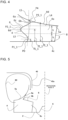
- the reference line L3 for the leading edge 6 is represented as a tangent passing through the point P1_1 and the point P3_1 at the opposite ends of the projection 6c in FIG. 4 and is represented as a straight line inclined toward the trailing edge 8 in a direction from the main plate 2 toward the shroud 5.
- the reference line L3 is a curve extending along the three-dimensionally twisted shape of the actual blade 4 and passing through the points P1_1 and P3_1.
- the reference line L3 is not limited to such a curve.
- the reference line L3 may be a straight line perpendicular to the main plate 2 or a straight line inclined at an angle to the main plate 2.
- setting the position at which the blade 4 has the longest circumferential length to satisfy f2_n > h, which is greater than half the outlet height, can reduce input power to the centrifugal fan to improve the efficiency of the fan.
- the recess 6b may be located at a level higher than or equal to the upper end of the trailing edge 8.
- the point P3_1 may satisfy a condition of "2h ⁇ f3_1". In this case, it is difficult to locate the bottom of the recess 6b closer to the trailing edge 8.
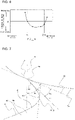
- FIG. 8 is a graph illustrating a change in input power to the centrifugal fan 1 associated with a change in angle ⁇ b and a change in angle ⁇ s in the centrifugal fan 1.
- the horizontal axis represents a change in ⁇ b - ⁇ s and the vertical axis represents a change in input power to the centrifugal fan 1 under conditions where the fluid flows through the centrifugal fan 1 at a constant flow rate.
- FIG. 8 demonstrates that as input power to the centrifugal fan 1 represented by the vertical axis is lower, the fluid can be discharged at the same flow rate with lower input power.
- a lower value on the vertical axis represents higher efficiency of the centrifugal fan 1.
- Embodiment 1 The efficiency of the centrifugal fan 1 according to Embodiment 1 can be improved by further specifying the angle formed by the connection part 6a of the leading edge 6 of each blade 4 and the shroud 5.
- Embodiment 9 a modification to Embodiment 8 is mainly described.
- the centrifugal fan 1 can be included not only in the heat source unit 40 of the air-conditioning apparatus described in Embodiment 1 but also in other units and apparatuses.
- an air-conditioning-apparatus indoor unit 53 including the centrifugal fan 1 is described as an example.
Claims (11)
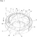
- Zentrifugallüfter (1), welcher Folgendes aufweist:- eine Hauptplatte (2);- eine Schaufel (4), die mit der Hauptplatte (2) verbunden ist; und- ein Umhüllung (5), die eine ringförmige Gestalt aufweist und mit einem umhüllungsseitigen Ende (4d) der Schaufel (4) verbunden ist, das zu einem hauptplattenseitigen Ende (4c) der mit der Hauptplatte (2) verbundenen Schaufel (4) entgegengesetzt ist,wobei der Zentrifugallüfter (1) so konfiguriert ist, dass er sich um eine Rotationsachse (X) dreht, um ein Fluid durch eine Öffnung der Umhüllung (5) anzusaugen und das Fluid durch die Schaufel (4) in einer radialen Richtung abzugeben,wobei die Schaufel (4) Folgendes aufweist:- eine Vorderkante (6), bei der es sich um eine Kante der Schaufel (4) handelt, die sich in einer Drehrichtung vorne befindet, und- eine Hinterkante (8), die eine zur Vorderkante (6) entgegengesetzte Kante ist und weiter von der Rotationsachse (X) entfernt ist als die Vorderkante (6),wobei eine Länge der Schaufel (4) von der Vorderkante (6) bis zur Hinterkante (8) in einem zur Hauptplatte (2) parallelen Abschnitt eine Umfangslänge ist, ein Abstand zwischen einer Umfangskante der Hauptplatte (2) und einer Umfangskante der Umhüllung (5) eine Auslasshöhe ist, wobei ein Teil der Schaufel (4), der eine größte Umfangslänge hat, näher an der Umhüllung (5) liegt als eine Mitte der Auslasshöhe,wobei die Vorderkante (6) Folgendes aufweist:- eine Aussparung (6b), die sich neben einem Punkt P4 befindet, an dem eine Umhüllungsinnenfläche (5a) der Umhüllung (5), die der Hauptplatte (2) zugewandt ist, mit der Vorderkante (6) verbunden ist, wobei die Aussparung (6b) einen Verbindungsteil (6a) aufweist, der sich von dem Punkt P4 in Richtung der Hinterkante (8) erstreckt und eine talartige Form mit einem Boden definiert, wenn die Aussparung (6b) von der Rotationsachse (X) aus betrachtet wird, und- einen Vorsprung (6c), der näher an der Hauptplatte (2) angeordnet ist als die Aussparung (6b), wobei der Vorsprung (6c) in der Drehrichtung vorsteht und eine umgekehrte V-Form mit einer Spitze aufweist, wenn der Vorsprung (6c) von der Rotationsachse (X) aus betrachtet wird, wobei die Auslasshöhe 2h beträgt, ein Punkt, der eines der entgegengesetzten Enden des Vorsprungs (6c) ist und sich in der Nähe der Hauptplatte (2) befindet, ein Punkt P1_1 ist, ein Punkt, der ein anderes der entgegengesetzten Enden ist und sich in der Nähe der Umhüllung (5) befindet, einPunkt P3_1 ist, wobei ein Abstand f1_1 zwischen dem Punkt P1_1 und der Hauptplatte (2) so eingestellt ist, dass er 0,05 × 2h ≤ f1_1 ≤ 0,2 × 2h erfüllt,ein Abstand f3_1 zwischen dem Punkt P3_1 und der Hauptplatte (2) so eingestellt ist, dass er 0,8 × 2h ≤ f3_1 ≤ 1,3 × 2h erfüllt.
- Zentrifugallüfter (1) nach Anspruch 1,
wobei eine Tangente L1 an die innere Oberfläche der Umhüllung im Punkt P4 und eine Tangente L2 an die Vorderkante (6) im Punkt P4 einen Winkel von 90 Grad oder weniger bilden. - Zentrifugallüfter (1) nach Anspruch 2,
wobei ein Winkel θs, gebildet durch die Tangente L1 und eine gerade Linie L5 parallel zur Rotationsachse (X), und ein Winkel θb, gebildet durch die Tangente L1 und die Tangente L2 an die Vorderkante (6), im Punkt P4, so eingestellt sind, dass 0 Grad ≤ θb < θs erfüllt wird. - Zentrifugallüfter nach Anspruch 3,
wobei der Winkel θs und der Winkel θb so eingestellt sind, dass sie 0 Grad ≤ θb < θs/2 erfüllen. - Zentrifugallüfter nach Anspruch 3 oder 4,
wobei der Winkel θs so eingestellt ist, dass er 0 Grad ≤ θs < 60 Grad erfüllt. - Zentrifugallüfter nach einem der Ansprüche 1 bis 5,
wobei ein Punkt an der Vorderkante (6) des Teils mit der längsten Umfangslänge ein Punkt P2_1 ist und eine Änderung der Umfangslänge zwischen den Punkten P2_1 und P3_1, die einer Abstandsänderung in einer Richtung entlang der Rotationsachse (X) zugeordnet ist, größer ist als eine Änderung der Umfangslänge zwischen den Punkten P1_1 und P2_1, die einer Abstandsänderung in der Richtung entlang der Rotationsachse (X) zugeordnet ist. - Zentrifugallüfter nach einem der Ansprüche 1 bis 6,
wobei der Vorsprung (6c) nahtlos in die Aussparung übergeht. - Zentrifugallüfter nach Anspruch 7,
wobei die Vorderkante (6) eine Gestalt hat, die eine Sinusform aufweist, die mindestens einer halben Periode einer Sinuskurve entspricht, wenn die Vorderkante (6) in einer radialen Richtung projiziert wird. - Zentrifugallüfter nach einem der Ansprüche 1 bis 8,
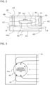
wobei ein Punkt, an dem die Innenfläche der Umhüllung (5) mit einer Ansaugfläche (4a) der Schaufel (4) verbunden ist, die der Rotationsachse (X) in einem Abschnitt gegenüberliegt, der die Rotationsachse (X) enthält, ein Punkt Q ist, ein Winkel, der an dem Punkt Q zwischen einer Tangente L6 an die Innenfläche der Umhüllung (5) und einer Linie parallel zu der Rotationsachse (X) gebildet ist, ein Winkel θq ist, ein Winkel, der zwischen der Tangente L6 und einer Tangente L8 an die Ansaugfläche (4a) in Q ein Winkel θh ist, und der Winkel θh so eingestellt ist, dass er 0 Grad ≤ θh < θq erfüllt. - Klimaanlage, welche eine Wärmequelleneinheit (40) und eine lastseitige Einheit aufweist,
wobei mindestens eine der Wärmequelleneinheit (40) und der lastseitigen Einheit den Zentrifugallüfter (1) nach einem der Ansprüche 1 bis 9 aufweist. - Klimaanlage nach Anspruch 10,wobei die Wärmequelleneinheit (40) einen Wärmetauscher (43) und den Zentrifugallüfter (1) in einem Gehäuse (44) aufweist,wobei das Gehäuse (44) eine von einer Seitenfläche des Gehäuses (44) abnehmbare Platte aufweist, undwobei die Seitenfläche mit der abgenommenen Platte als ein Lufteinlass oder ein Luftauslass der Wärmequelleneinheit (40) verwendet wird.
Applications Claiming Priority (1)
| Application Number | Priority Date | Filing Date | Title |
|---|---|---|---|
| PCT/JP2018/045896 WO2020121484A1 (ja) | 2018-12-13 | 2018-12-13 | 遠心ファン及び空気調和機 |
Publications (3)
| Publication Number | Publication Date |
|---|---|
| EP3896290A1 EP3896290A1 (de) | 2021-10-20 |
| EP3896290A4 EP3896290A4 (de) | 2021-12-15 |
| EP3896290B1 true EP3896290B1 (de) | 2023-03-29 |
Family
ID=70682444
Family Applications (1)
| Application Number | Title | Priority Date | Filing Date |
|---|---|---|---|
| EP18943319.6A Active EP3896290B1 (de) | 2018-12-13 | 2018-12-13 | Zentrifugallüfter und klimaanlage |
Country Status (6)
| Country | Link |
|---|---|
| US (1) | US11674520B2 (de) |
| EP (1) | EP3896290B1 (de) |
| JP (1) | JP6695509B1 (de) |
| CN (1) | CN113167289B (de) |
| ES (1) | ES2942991T3 (de) |
| WO (1) | WO2020121484A1 (de) |
Families Citing this family (2)
| Publication number | Priority date | Publication date | Assignee | Title |
|---|---|---|---|---|
| US20220205650A1 (en) * | 2020-12-25 | 2022-06-30 | Samsung Electronics Co., Ltd. | Air conditioner including a centrifugal fan |
| WO2022139498A1 (ko) * | 2020-12-25 | 2022-06-30 | 삼성전자주식회사 | 원심팬을 구비하는 공기 조화기 |
Family Cites Families (17)
| Publication number | Priority date | Publication date | Assignee | Title |
|---|---|---|---|---|
| JPS50157735U (de) * | 1974-06-13 | 1975-12-26 | ||
| JP3391318B2 (ja) * | 1999-11-16 | 2003-03-31 | ダイキン工業株式会社 | 遠心ファン及び該ファンを備えた空気調和機 |
| JP3978083B2 (ja) * | 2001-06-12 | 2007-09-19 | 漢拏空調株式会社 | 軸流ファン |
| KR100820857B1 (ko) * | 2003-03-05 | 2008-04-10 | 한라공조주식회사 | 축류팬 |
| JP2005233057A (ja) | 2004-02-19 | 2005-09-02 | Mitsubishi Heavy Ind Ltd | 遷音速流体用の圧縮機 |
| JP4663259B2 (ja) * | 2004-06-18 | 2011-04-06 | 日立アプライアンス株式会社 | 送風機及び電気掃除機 |
| JP2009074385A (ja) * | 2007-09-19 | 2009-04-09 | Ihi Corp | 遠心圧縮機 |
| JP4612084B2 (ja) * | 2008-08-29 | 2011-01-12 | 株式会社日立産機システム | 遠心ファン、及び、それを用いた空気流体機械 |
| KR101761311B1 (ko) * | 2010-09-02 | 2017-07-25 | 엘지전자 주식회사 | 공기조화기용 터보팬 |
| JP2012085836A (ja) * | 2010-10-20 | 2012-05-10 | Panasonic Corp | 洗濯乾燥機 |
| CN102536892A (zh) * | 2012-03-10 | 2012-07-04 | 广东恒业电器有限公司 | 具有强化进气功能的多翼式离心风机 |
| JP5783214B2 (ja) | 2013-09-30 | 2015-09-24 | ダイキン工業株式会社 | 遠心送風機及びこれを備えた空気調和機 |
| US9523370B2 (en) * | 2014-04-07 | 2016-12-20 | Hanon Systems | Blower with curved blades |
| US10400605B2 (en) | 2014-10-30 | 2019-09-03 | Mitsubishi Electric Corporation | Turbofan and indoor unit for air conditioning apparatus |
| JP2016121580A (ja) * | 2014-12-24 | 2016-07-07 | ダイキン工業株式会社 | 遠心型送風機 |
| CN204828043U (zh) * | 2015-08-03 | 2015-12-02 | 江森自控楼宇设备科技(无锡)有限公司 | 叶片 |
| JP2019127865A (ja) * | 2018-01-23 | 2019-08-01 | 株式会社デンソー | 遠心ファン |
-
2018
- 2018-12-13 JP JP2019537187A patent/JP6695509B1/ja active Active
- 2018-12-13 WO PCT/JP2018/045896 patent/WO2020121484A1/ja unknown
- 2018-12-13 ES ES18943319T patent/ES2942991T3/es active Active
- 2018-12-13 CN CN201880099721.9A patent/CN113167289B/zh active Active
- 2018-12-13 EP EP18943319.6A patent/EP3896290B1/de active Active
- 2018-12-13 US US17/287,125 patent/US11674520B2/en active Active
Also Published As
| Publication number | Publication date |
|---|---|
| EP3896290A4 (de) | 2021-12-15 |
| JP6695509B1 (ja) | 2020-05-20 |
| JPWO2020121484A1 (ja) | 2021-02-15 |
| US20210381513A1 (en) | 2021-12-09 |
| US11674520B2 (en) | 2023-06-13 |
| WO2020121484A1 (ja) | 2020-06-18 |
| CN113167289B (zh) | 2023-03-24 |
| ES2942991T3 (es) | 2023-06-08 |
| CN113167289A (zh) | 2021-07-23 |
| EP3896290A1 (de) | 2021-10-20 |
Similar Documents
| Publication | Publication Date | Title |
|---|---|---|
| US9995303B2 (en) | Air conditioner | |
| EP2618066B1 (de) | Gebläse für eine ausseneinheit, ausseneinheit und kältekreislaufvorrichtung | |
| JP6415741B2 (ja) | 送風機、および、それを備えた空気調和装置 | |
| EP3372839B1 (de) | Gebläse, ausseneinheit und kühlzyklusvorrichtung | |
| EP2781844B1 (de) | Turbolüfter und Deckenklimaanlage damit | |
| US10890194B2 (en) | Air-sending device and air-conditioning apparatus using the same | |
| TW200530539A (en) | Integral air conditioner | |
| EP3896290B1 (de) | Zentrifugallüfter und klimaanlage | |
| JP2007205268A (ja) | 遠心ファン | |
| JP2701604B2 (ja) | 空気調和装置 | |
| KR100468468B1 (ko) | 공기조화기의 실내기 | |
| JP2014240633A (ja) | 送風機及び送風機を搭載した室外ユニット | |
| KR20200037945A (ko) | 팬 어셈블리 | |
| JP2012002165A (ja) | ターボファンおよびそれを用いた空気調和機 | |
| JP2013053532A (ja) | 軸流送風機及び空気調和機 | |
| CN109891101B (zh) | 螺旋桨风扇、室外机和制冷循环装置 | |
| KR100295964B1 (ko) | 천장형에어컨의실내기 | |
| JP6430032B2 (ja) | 遠心ファン、空気調和装置および冷凍サイクル装置 | |
| CN110741207A (zh) | 空调器 | |
| JP7458552B2 (ja) | 送風装置 | |
| WO2020147751A1 (zh) | 立式空调器室内机 | |
| WO2020147750A1 (zh) | 立式空调器室内机 | |
| WO2023112077A1 (ja) | 軸流ファン、送風機、および、冷凍サイクル装置 | |
| KR101871723B1 (ko) | 실내기 및 그것을 구비하는 공기조화기 | |
| JPH0321811B2 (de) |
Legal Events
| Date | Code | Title | Description |
|---|---|---|---|
| STAA | Information on the status of an ep patent application or granted ep patent |
Free format text: STATUS: THE INTERNATIONAL PUBLICATION HAS BEEN MADE |
|
| PUAI | Public reference made under article 153(3) epc to a published international application that has entered the european phase |
Free format text: ORIGINAL CODE: 0009012 |
|
| STAA | Information on the status of an ep patent application or granted ep patent |
Free format text: STATUS: REQUEST FOR EXAMINATION WAS MADE |
|
| 17P | Request for examination filed |
Effective date: 20210609 |
|
| AK | Designated contracting states |
Kind code of ref document: A1 Designated state(s): AL AT BE BG CH CY CZ DE DK EE ES FI FR GB GR HR HU IE IS IT LI LT LU LV MC MK MT NL NO PL PT RO RS SE SI SK SM TR |
|
| A4 | Supplementary search report drawn up and despatched |
Effective date: 20211112 |
|
| RIC1 | Information provided on ipc code assigned before grant |
Ipc: F24F 1/38 20110101ALI20211108BHEP Ipc: F24F 1/0022 20190101ALI20211108BHEP Ipc: F04D 29/30 20060101AFI20211108BHEP |
|
| DAV | Request for validation of the european patent (deleted) | ||
| DAX | Request for extension of the european patent (deleted) | ||
| REG | Reference to a national code |
Ref country code: DE Ref legal event code: R079 Ref document number: 602018047934 Country of ref document: DE Free format text: PREVIOUS MAIN CLASS: F04D0029300000 Ipc: F04D0029280000 |
|
| GRAP | Despatch of communication of intention to grant a patent |
Free format text: ORIGINAL CODE: EPIDOSNIGR1 |
|
| STAA | Information on the status of an ep patent application or granted ep patent |
Free format text: STATUS: GRANT OF PATENT IS INTENDED |
|
| RIC1 | Information provided on ipc code assigned before grant |
Ipc: F24F 1/38 20110101ALI20220909BHEP Ipc: F24F 1/0022 20190101ALI20220909BHEP Ipc: F04D 29/30 20060101ALI20220909BHEP Ipc: F04D 29/28 20060101AFI20220909BHEP |
|
| INTG | Intention to grant announced |
Effective date: 20221007 |
|
| GRAS | Grant fee paid |
Free format text: ORIGINAL CODE: EPIDOSNIGR3 |
|
| GRAA | (expected) grant |
Free format text: ORIGINAL CODE: 0009210 |
|
| STAA | Information on the status of an ep patent application or granted ep patent |
Free format text: STATUS: THE PATENT HAS BEEN GRANTED |
|
| AK | Designated contracting states |
Kind code of ref document: B1 Designated state(s): AL AT BE BG CH CY CZ DE DK EE ES FI FR GB GR HR HU IE IS IT LI LT LU LV MC MK MT NL NO PL PT RO RS SE SI SK SM TR |
|
| REG | Reference to a national code |
Ref country code: CH Ref legal event code: EP |
|
| REG | Reference to a national code |
Ref country code: DE Ref legal event code: R096 Ref document number: 602018047934 Country of ref document: DE |
|
| REG | Reference to a national code |
Ref country code: AT Ref legal event code: REF Ref document number: 1556847 Country of ref document: AT Kind code of ref document: T Effective date: 20230415 |
|
| REG | Reference to a national code |
Ref country code: IE Ref legal event code: FG4D |
|
| REG | Reference to a national code |
Ref country code: ES Ref legal event code: FG2A Ref document number: 2942991 Country of ref document: ES Kind code of ref document: T3 Effective date: 20230608 |
|
| REG | Reference to a national code |
Ref country code: LT Ref legal event code: MG9D |
|
| PG25 | Lapsed in a contracting state [announced via postgrant information from national office to epo] |
Ref country code: RS Free format text: LAPSE BECAUSE OF FAILURE TO SUBMIT A TRANSLATION OF THE DESCRIPTION OR TO PAY THE FEE WITHIN THE PRESCRIBED TIME-LIMIT Effective date: 20230329 Ref country code: NO Free format text: LAPSE BECAUSE OF FAILURE TO SUBMIT A TRANSLATION OF THE DESCRIPTION OR TO PAY THE FEE WITHIN THE PRESCRIBED TIME-LIMIT Effective date: 20230629 Ref country code: LV Free format text: LAPSE BECAUSE OF FAILURE TO SUBMIT A TRANSLATION OF THE DESCRIPTION OR TO PAY THE FEE WITHIN THE PRESCRIBED TIME-LIMIT Effective date: 20230329 Ref country code: LT Free format text: LAPSE BECAUSE OF FAILURE TO SUBMIT A TRANSLATION OF THE DESCRIPTION OR TO PAY THE FEE WITHIN THE PRESCRIBED TIME-LIMIT Effective date: 20230329 Ref country code: HR Free format text: LAPSE BECAUSE OF FAILURE TO SUBMIT A TRANSLATION OF THE DESCRIPTION OR TO PAY THE FEE WITHIN THE PRESCRIBED TIME-LIMIT Effective date: 20230329 |
|
| REG | Reference to a national code |
Ref country code: NL Ref legal event code: MP Effective date: 20230329 |
|
| REG | Reference to a national code |
Ref country code: AT Ref legal event code: MK05 Ref document number: 1556847 Country of ref document: AT Kind code of ref document: T Effective date: 20230329 |
|
| P01 | Opt-out of the competence of the unified patent court (upc) registered |
Effective date: 20230711 |
|
| PG25 | Lapsed in a contracting state [announced via postgrant information from national office to epo] |
Ref country code: SE Free format text: LAPSE BECAUSE OF FAILURE TO SUBMIT A TRANSLATION OF THE DESCRIPTION OR TO PAY THE FEE WITHIN THE PRESCRIBED TIME-LIMIT Effective date: 20230329 Ref country code: NL Free format text: LAPSE BECAUSE OF FAILURE TO SUBMIT A TRANSLATION OF THE DESCRIPTION OR TO PAY THE FEE WITHIN THE PRESCRIBED TIME-LIMIT Effective date: 20230329 Ref country code: GR Free format text: LAPSE BECAUSE OF FAILURE TO SUBMIT A TRANSLATION OF THE DESCRIPTION OR TO PAY THE FEE WITHIN THE PRESCRIBED TIME-LIMIT Effective date: 20230630 Ref country code: FI Free format text: LAPSE BECAUSE OF FAILURE TO SUBMIT A TRANSLATION OF THE DESCRIPTION OR TO PAY THE FEE WITHIN THE PRESCRIBED TIME-LIMIT Effective date: 20230329 |
|
| PG25 | Lapsed in a contracting state [announced via postgrant information from national office to epo] |
Ref country code: SM Free format text: LAPSE BECAUSE OF FAILURE TO SUBMIT A TRANSLATION OF THE DESCRIPTION OR TO PAY THE FEE WITHIN THE PRESCRIBED TIME-LIMIT Effective date: 20230329 Ref country code: RO Free format text: LAPSE BECAUSE OF FAILURE TO SUBMIT A TRANSLATION OF THE DESCRIPTION OR TO PAY THE FEE WITHIN THE PRESCRIBED TIME-LIMIT Effective date: 20230329 Ref country code: PT Free format text: LAPSE BECAUSE OF FAILURE TO SUBMIT A TRANSLATION OF THE DESCRIPTION OR TO PAY THE FEE WITHIN THE PRESCRIBED TIME-LIMIT Effective date: 20230731 Ref country code: EE Free format text: LAPSE BECAUSE OF FAILURE TO SUBMIT A TRANSLATION OF THE DESCRIPTION OR TO PAY THE FEE WITHIN THE PRESCRIBED TIME-LIMIT Effective date: 20230329 Ref country code: AT Free format text: LAPSE BECAUSE OF FAILURE TO SUBMIT A TRANSLATION OF THE DESCRIPTION OR TO PAY THE FEE WITHIN THE PRESCRIBED TIME-LIMIT Effective date: 20230329 |
|
| PG25 | Lapsed in a contracting state [announced via postgrant information from national office to epo] |
Ref country code: SK Free format text: LAPSE BECAUSE OF FAILURE TO SUBMIT A TRANSLATION OF THE DESCRIPTION OR TO PAY THE FEE WITHIN THE PRESCRIBED TIME-LIMIT Effective date: 20230329 Ref country code: PL Free format text: LAPSE BECAUSE OF FAILURE TO SUBMIT A TRANSLATION OF THE DESCRIPTION OR TO PAY THE FEE WITHIN THE PRESCRIBED TIME-LIMIT Effective date: 20230329 Ref country code: IS Free format text: LAPSE BECAUSE OF FAILURE TO SUBMIT A TRANSLATION OF THE DESCRIPTION OR TO PAY THE FEE WITHIN THE PRESCRIBED TIME-LIMIT Effective date: 20230729 |
|
| REG | Reference to a national code |
Ref country code: DE Ref legal event code: R097 Ref document number: 602018047934 Country of ref document: DE |
|
| PGFP | Annual fee paid to national office [announced via postgrant information from national office to epo] |
Ref country code: GB Payment date: 20231102 Year of fee payment: 6 |
|
| PG25 | Lapsed in a contracting state [announced via postgrant information from national office to epo] |
Ref country code: DK Free format text: LAPSE BECAUSE OF FAILURE TO SUBMIT A TRANSLATION OF THE DESCRIPTION OR TO PAY THE FEE WITHIN THE PRESCRIBED TIME-LIMIT Effective date: 20230329 Ref country code: CZ Free format text: LAPSE BECAUSE OF FAILURE TO SUBMIT A TRANSLATION OF THE DESCRIPTION OR TO PAY THE FEE WITHIN THE PRESCRIBED TIME-LIMIT Effective date: 20230329 |
|
| PGFP | Annual fee paid to national office [announced via postgrant information from national office to epo] |
Ref country code: DE Payment date: 20231031 Year of fee payment: 6 |
|
| PLBE | No opposition filed within time limit |
Free format text: ORIGINAL CODE: 0009261 |
|
| STAA | Information on the status of an ep patent application or granted ep patent |
Free format text: STATUS: NO OPPOSITION FILED WITHIN TIME LIMIT |
|
| 26N | No opposition filed |
Effective date: 20240103 |
|
| PGFP | Annual fee paid to national office [announced via postgrant information from national office to epo] |
Ref country code: ES Payment date: 20240110 Year of fee payment: 6 |