EP3896290B1 - Centrifugal fan and air conditioner - Google Patents
Centrifugal fan and air conditioner Download PDFInfo
- Publication number
- EP3896290B1 EP3896290B1 EP18943319.6A EP18943319A EP3896290B1 EP 3896290 B1 EP3896290 B1 EP 3896290B1 EP 18943319 A EP18943319 A EP 18943319A EP 3896290 B1 EP3896290 B1 EP 3896290B1
- Authority
- EP
- European Patent Office
- Prior art keywords
- centrifugal fan
- shroud
- blade
- point
- leading edge
- Prior art date
- Legal status (The legal status is an assumption and is not a legal conclusion. Google has not performed a legal analysis and makes no representation as to the accuracy of the status listed.)
- Active
Links
- 239000012530 fluid Substances 0.000 claims description 38
- 238000004378 air conditioning Methods 0.000 claims description 19
- 230000002093 peripheral effect Effects 0.000 claims 2
- 238000000926 separation method Methods 0.000 description 37
- 230000000694 effects Effects 0.000 description 13
- 230000007423 decrease Effects 0.000 description 8
- 238000010586 diagram Methods 0.000 description 8
- 230000004048 modification Effects 0.000 description 8
- 238000012986 modification Methods 0.000 description 8
- 238000005192 partition Methods 0.000 description 4
- 239000003507 refrigerant Substances 0.000 description 4
- 230000001154 acute effect Effects 0.000 description 3
- 238000001816 cooling Methods 0.000 description 3
- 239000013585 weight reducing agent Substances 0.000 description 3
- 238000004891 communication Methods 0.000 description 2
- 238000003780 insertion Methods 0.000 description 2
- 230000037431 insertion Effects 0.000 description 2
- 238000005057 refrigeration Methods 0.000 description 2
- XLYOFNOQVPJJNP-UHFFFAOYSA-N water Substances O XLYOFNOQVPJJNP-UHFFFAOYSA-N 0.000 description 2
- 241001012508 Carpiodes cyprinus Species 0.000 description 1
- 238000013459 approach Methods 0.000 description 1
- 230000005494 condensation Effects 0.000 description 1
- 238000009833 condensation Methods 0.000 description 1
- 230000003247 decreasing effect Effects 0.000 description 1
- 230000005484 gravity Effects 0.000 description 1
- 230000001788 irregular Effects 0.000 description 1
- 239000007788 liquid Substances 0.000 description 1
- 238000007493 shaping process Methods 0.000 description 1
Images


Classifications
-
- F—MECHANICAL ENGINEERING; LIGHTING; HEATING; WEAPONS; BLASTING
- F04—POSITIVE - DISPLACEMENT MACHINES FOR LIQUIDS; PUMPS FOR LIQUIDS OR ELASTIC FLUIDS
- F04D—NON-POSITIVE-DISPLACEMENT PUMPS
- F04D17/00—Radial-flow pumps, e.g. centrifugal pumps; Helico-centrifugal pumps
- F04D17/08—Centrifugal pumps
- F04D17/10—Centrifugal pumps for compressing or evacuating
-
- F—MECHANICAL ENGINEERING; LIGHTING; HEATING; WEAPONS; BLASTING
- F04—POSITIVE - DISPLACEMENT MACHINES FOR LIQUIDS; PUMPS FOR LIQUIDS OR ELASTIC FLUIDS
- F04D—NON-POSITIVE-DISPLACEMENT PUMPS
- F04D29/00—Details, component parts, or accessories
- F04D29/26—Rotors specially for elastic fluids
- F04D29/28—Rotors specially for elastic fluids for centrifugal or helico-centrifugal pumps for radial-flow or helico-centrifugal pumps
- F04D29/281—Rotors specially for elastic fluids for centrifugal or helico-centrifugal pumps for radial-flow or helico-centrifugal pumps for fans or blowers
-
- F—MECHANICAL ENGINEERING; LIGHTING; HEATING; WEAPONS; BLASTING
- F04—POSITIVE - DISPLACEMENT MACHINES FOR LIQUIDS; PUMPS FOR LIQUIDS OR ELASTIC FLUIDS
- F04D—NON-POSITIVE-DISPLACEMENT PUMPS
- F04D29/00—Details, component parts, or accessories
- F04D29/26—Rotors specially for elastic fluids
- F04D29/28—Rotors specially for elastic fluids for centrifugal or helico-centrifugal pumps for radial-flow or helico-centrifugal pumps
- F04D29/30—Vanes
-
- F—MECHANICAL ENGINEERING; LIGHTING; HEATING; WEAPONS; BLASTING
- F04—POSITIVE - DISPLACEMENT MACHINES FOR LIQUIDS; PUMPS FOR LIQUIDS OR ELASTIC FLUIDS
- F04D—NON-POSITIVE-DISPLACEMENT PUMPS
- F04D29/00—Details, component parts, or accessories
- F04D29/58—Cooling; Heating; Diminishing heat transfer
- F04D29/582—Cooling; Heating; Diminishing heat transfer specially adapted for elastic fluid pumps
- F04D29/584—Cooling; Heating; Diminishing heat transfer specially adapted for elastic fluid pumps cooling or heating the machine
-
- F—MECHANICAL ENGINEERING; LIGHTING; HEATING; WEAPONS; BLASTING
- F24—HEATING; RANGES; VENTILATING
- F24F—AIR-CONDITIONING; AIR-HUMIDIFICATION; VENTILATION; USE OF AIR CURRENTS FOR SCREENING
- F24F1/00—Room units for air-conditioning, e.g. separate or self-contained units or units receiving primary air from a central station
- F24F1/0007—Indoor units, e.g. fan coil units
- F24F1/0018—Indoor units, e.g. fan coil units characterised by fans
- F24F1/0022—Centrifugal or radial fans
Definitions
- the blade of the centrifugal fan mounted in the air-conditioning apparatus, if the blade of the centrifugal fan is located at a short distance from the heat exchanger such that a flow field on the suction surface may become unstable, flow separation at the leading edge of the blade is reduced, and a large-scale stall zone in a region between the leading edge and the trailing edge on the suction surface of the blade is thus eliminated.
- the eliminated large-scale stall zone results in noise reduction and a significant increase in flow rate to improve the efficiency of the fan.
- the reference line L3 for the leading edge 6 is represented as a tangent passing through the point P1_1 and the point P3_1 at the opposite ends of the projection 6c in FIG. 4 and is represented as a straight line inclined toward the trailing edge 8 in a direction from the main plate 2 toward the shroud 5.
- the reference line L3 is a curve extending along the three-dimensionally twisted shape of the actual blade 4 and passing through the points P1_1 and P3_1.
- the reference line L3 is not limited to such a curve.
- the reference line L3 may be a straight line perpendicular to the main plate 2 or a straight line inclined at an angle to the main plate 2.
- setting the position at which the blade 4 has the longest circumferential length to satisfy f2_n > h, which is greater than half the outlet height, can reduce input power to the centrifugal fan to improve the efficiency of the fan.
- the recess 6b may be located at a level higher than or equal to the upper end of the trailing edge 8.
- the point P3_1 may satisfy a condition of "2h ⁇ f3_1". In this case, it is difficult to locate the bottom of the recess 6b closer to the trailing edge 8.
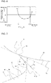
- FIG. 8 is a graph illustrating a change in input power to the centrifugal fan 1 associated with a change in angle ⁇ b and a change in angle ⁇ s in the centrifugal fan 1.
- the horizontal axis represents a change in ⁇ b - ⁇ s and the vertical axis represents a change in input power to the centrifugal fan 1 under conditions where the fluid flows through the centrifugal fan 1 at a constant flow rate.
- FIG. 8 demonstrates that as input power to the centrifugal fan 1 represented by the vertical axis is lower, the fluid can be discharged at the same flow rate with lower input power.
- a lower value on the vertical axis represents higher efficiency of the centrifugal fan 1.
- Embodiment 1 The efficiency of the centrifugal fan 1 according to Embodiment 1 can be improved by further specifying the angle formed by the connection part 6a of the leading edge 6 of each blade 4 and the shroud 5.
- Embodiment 9 a modification to Embodiment 8 is mainly described.
- the centrifugal fan 1 can be included not only in the heat source unit 40 of the air-conditioning apparatus described in Embodiment 1 but also in other units and apparatuses.
- an air-conditioning-apparatus indoor unit 53 including the centrifugal fan 1 is described as an example.
Description
- The present invention relates to a centrifugal fan and an air-conditioning apparatus including the centrifugal fan, and in particular, relates to the shape of blades of the centrifugal fan.
- Some centrifugal fans such as a centrifugal fan disclosed in
Patent Literature 1 are used to send a gas such as air or a liquid such as water and refrigerant. The centrifugal fans each include a plurality of blades arranged in a circumferential direction and a disc-shaped or cup-shaped hub disposed at first ends of the blades in an axial direction. Some centrifugal fan includes an annular shroud disposed at second ends of the blades opposite from the hub. - In an air-conditioning apparatus including, as an air-sending device, a centrifugal fan, the centrifugal fan is rotated by a motor, a fluid is suctioned into the air-conditioning apparatus through an air inlet, the fluid is guided to a shroud of the centrifugal fan along an inner circumferential surface of a bell mouth, and the fluid is then discharged radially through a plurality of blades arranged circumferentially about the axis of rotation of the centrifugal fan.
- Part of the fluid radially discharged through the blades passes through a space between an outer circumferential surface of the shroud and a casing, passes through a space between an outer circumferential surface of the bell mouth and an inner circumferential surface of the shroud, and is then guided to the shroud of the centrifugal fan. Hereinafter, this flow is referred to as a circulating flow.
- Air that is radially discharged through the blades of the centrifugal fan and is not included in the circulating flow passes through a heat exchanger of the air-conditioning apparatus and is then discharged to the outside of the air-conditioning apparatus. The above-described circulating flow moves at high velocity when passing through the space between the outer circumferential surface of the bell mouth and the inner circumferential surface of the shroud.
- For this reason, collision of the circulating flow passing past the inner circumferential surface of the shroud with leading edges of the blades of the centrifugal fan increases noise from the centrifugal fan and causes flow separation of the fluid in a region adjacent to the shroud, or a shroud-side region, on a suction surface of the leading edge of each blade. In particular, at a position where trailing edges of the blades located at the outside diameter of the centrifugal fan are located closest to the heat exchanger of the air-conditioning apparatus, the air flow separation in the shroud-side region on the suction surface of each leading edge extends a stall zone toward the trailing edge.
- Consequently, the stall zone is widely extended from the leading edge to the trailing edge in the shroud-side region on the suction surface of each blade, and a significant reduction in efficiency of the centrifugal fan is thus caused.
- For such a centrifugal fan, the shape of each blade is changed to achieve efficiency improvement and noise reduction.
- Patent Literature 1: Japanese Unexamined Patent Application Publication
JP 2015-068310 A JP 2012 085836 - A high-velocity circulating flow enters a centrifugal fan through a space defined between a shroud and a bell mouth of the centrifugal fan. The circulating flow flows along an inner surface of the shroud to blades. In a structure disclosed in
Patent Literature 1, a blade angle distribution in which the blade angle is constant or decreases along a camber line is provided to reduce noise caused by a circulating flow. Disadvantageously, this structure has a small effect of reducing flow separation at the leading edge of each blade. Specifically, in a centrifugal fan with such a structure, flow separation of a fluid is likely to occur in a shroud-side region on a suction surface of each blade, and the efficiency of the fan is thus reduced. - In particular, in the centrifugal fan mounted in an air-conditioning apparatus such that the blades of the centrifugal fan are arranged at a short distance from a heat exchanger, large-scale flow separation occurs in the shroud-side region on the suction surface of each blade between the leading edge and the trailing edge of the blade. Disadvantageously, such large-scale flow separation significantly affects a reduction in efficiency of the centrifugal fan.
- The present invention is intended to overcome the above-described disadvantages and aims to provide a centrifugal fan and an air-conditioning apparatus in which flow separation in a shroud-side region on a suction surface of a blade of the centrifugal fan is reduced to improve efficiency.
- A centrifugal fan according to one embodiment of the present invention includes a main plate, a blade connected to the main plate, and a shroud having an annular shape and connected to a shroud-side end of the blade that is an end opposite a main-plate-side end of the blade connected to the main plate. The centrifugal fan is configured to rotate about a rotation axis to suction a fluid through an opening of the shroud and discharge the fluid through the blade in a radial direction.
- The blade has a leading edge that is an edge of the blade located forward in a rotation direction and a trailing edge that is an edge opposite the leading edge and is located farther from the rotation axis than is the leading edge. The leading edge includes a recess located next to a point P4 at which a shroud inner surface of the shroud that faces the main plate is connected to the leading edge and curving inwardly from the point P4 toward the trailing edge and a projection located closer to the main plate than is the recess and projecting in the rotation direction.
- An air-conditioning apparatus according to another embodiment of the present invention includes a heat source unit and a load-side unit. At least one of the heat source unit and the load-side unit includes the above-described centrifugal fan.
- According to an embodiment of the present invention, reducing an angle formed by a tangent to the leading edge of the blade and a tangent to the shroud inner surface in the centrifugal fan reduces flow separation at the leading edge of the blade. Advantageously, the reduced flow separation results in a reduction in noise from the centrifugal fan and an increase in flow rate through the centrifugal fan to improve the efficiency of the fan.
In the centrifugal fan mounted in the air-conditioning apparatus, if the blade of the centrifugal fan is located at a short distance from the heat exchanger such that a flow field on the suction surface may become unstable, flow separation at the leading edge of the blade is reduced, and a large-scale stall zone in a region between the leading edge and the trailing edge on the suction surface of the blade is thus eliminated. The eliminated large-scale stall zone results in noise reduction and a significant increase in flow rate to improve the efficiency of the fan. -
- FIG. 1
- is a perspective view of a centrifugal fan according to Embodiment 1.
- FIG. 2
- is a sectional view illustrating the structure of a heat source unit including the centrifugal fan according to
Embodiment 1. - FIG. 3
- is a schematic diagram schematically illustrating an example of a section taken along line B-B in
FIG. 2 . - FIG. 4
- is a diagram illustrating the shape of each blade of the centrifugal fan according to
Embodiment 1. - FIG. 5
- is a schematic diagram of the structure of the centrifugal fan according to
Embodiment 1 in a section containing a rotation axis X. - FIG. 6
- is a graph illustrating the relationship between the position of a point on a projection of the blade and a change in input power to the centrifugal fan.
- FIG. 7
- is an enlarged view illustrating connection part of the blade of the centrifugal fan in
FIG. 4 and its surroundings. - FIG. 8
- is a graph illustrating a change in input power to the centrifugal fan associated with a change in angle θb and a change in angle θs in the centrifugal fan.
- FIG. 9
- is a plan view of the centrifugal fan of
FIG. 1 as the centrifugal fan is viewed from the position where a shroud is located. - FIG. 10
- is a diagram illustrating a section of the centrifugal fan of
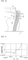
FIG. 1 that contains the rotation axis. - FIG. 11
- is a graph illustrating a change in input power to the centrifugal fan associated with a change in angle θq and a change in angle θh in the centrifugal fan.
- FIG. 12
- is a sectional view illustrating the structure of an air-conditioning-apparatus indoor unit including the centrifugal fan.
- Embodiments of a centrifugal fan and an air-conditioning apparatus including the centrifugal fan are described below. Note that the forms of components illustrated in the drawings are merely examples, and the present invention is not limited to the forms of components illustrated in the drawings. Furthermore, note that components designated by the same reference signs in the drawings are the same components or equivalents. This note applies to the entire description herein.
- Additionally, note that the forms of components described herein are merely examples and the present invention is not limited only to the description herein. In particular, a combination of components is not limited only to that in each embodiment. A component in one Embodiment can be used in another embodiment. Furthermore, note that the relationship between the sizes of the components in the drawings may differ from that of actual ones.
-
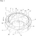
FIG. 1 is a perspective view of acentrifugal fan 1 according toEmbodiment 1. Thecentrifugal fan 1 includes amain plate 2, a plurality ofblades 4 standing from themain plate 2, and ashroud 5 disposed such that theblades 4 are interposed between themain plate 2 and theshroud 5. Themain plate 2 has a central hole through which a shaft extends and includes a cup-shapedhub 3 located around the hole and protruding from themain plate 2 toward theshroud 5. Theblades 4 are arranged circumferentially around thehub 3. - The
shroud 5 is secured to ends of theblades 4 opposite from ends of theblades 4 to which themain plate 2 is secured. Theshroud 5 has an annular shape. The central hole, to which the shaft connecting thecentrifugal fan 1 to a power unit to rotate thecentrifugal fan 1 is secured, of themain plate 2 is located at the center of rotation of thecentrifugal fan 1. -
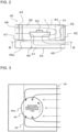
FIG. 2 is a sectional view illustrating the structure of aheat source unit 40 including thecentrifugal fan 1 according toEmbodiment 1.FIG. 2 schematically illustrates the inside of theheat source unit 40. Thecentrifugal fan 1 is mounted in, for example, an air-conditioning apparatus or a heat source unit, and is used after the rotation shaft is secured to a rotor of a vehicle-mounted alternator or a rotary electric machine, such as a motor. - In
Embodiment 1, thecentrifugal fan 1 mounted in theheat source unit 40 of an air-conditioning apparatus is described as an example. Although thecentrifugal fan 1 mounted in theheat source unit 40 is described inEmbodiment 1, thecentrifugal fan 1 is not limited to this example. Thecentrifugal fan 1 may be mounted in another device, such as an air-conditioning-apparatus indoor unit and an air-sending device. - The
heat source unit 40 is connected to a load-side unit, which is not illustrated, by refrigerant pipes to form a refrigeration cycle circuit. The air-conditioning apparatus circulates refrigerant through the refrigerant pipes in the refrigeration cycle circuit so that the load-side unit heats or cools an air-conditioned space. The air-conditioned space is a room of, for example, a house, a building, or a condominium. Theheat source unit 40 is used as an outdoor unit of the air-conditioning apparatus. The load-side unit is used as an indoor unit of the air-conditioning apparatus. - The
heat source unit 40 includes at least oneheat exchanger 43, acompressor 41, acontrol box 42, thecentrifugal fan 1, abell mouth 45, afan motor 50, and adrain pan 47 in acasing 44. Thecasing 44 is a shell of theheat source unit 40 and has anair inlet 46 and anair outlet 48. - The
air inlet 46 and theair outlet 48 are opened in thecasing 44 to provide communication between the inside and the outside of thecasing 44. Theair inlet 46 is opened in, for example, a rear wall of thecasing 44. Theair outlet 48 is opened in, for example, a front wall of thecasing 44. In other words, theheat source unit 40 is configured such that air is suctioned into theheat source unit 40 from one side face of thecasing 44 and the air is discharged from another side face of thecasing 44. - Each side face of the
casing 44 is divided into upper and lower panels, which are removable. InEmbodiment 1, the lower panel of one side face is removed to provide an opening that defines theair inlet 46. Furthermore, the upper panel of another side face of thecasing 44 is removed to provide an opening that defines theair outlet 48. - The
heat exchanger 43 is disposed between theair outlet 48 and thecentrifugal fan 1 and is disposed downstream of thecentrifugal fan 1. Thedrain pan 47 is disposed under theheat exchanger 43 and receives, for example, condensation water that falls from theheat exchanger 43. Thecentrifugal fan 1 has a rotation axis X and rotates about the rotation axis X to send a fluid from thebell mouth 45 to theheat exchanger 43. Thecentrifugal fan 1 is connected at a center O to thefan motor 50 and is driven to rotate. - The
bell mouth 45 is disposed at part of thecentrifugal fan 1 through which a fluid is suctioned and guides the fluid flowing through anair inlet passage 51 to thecentrifugal fan 1. Thebell mouth 45 includes a portion having an opening that gradually decreases in diameter from its inlet adjacent to theair inlet passage 51 toward thecentrifugal fan 1. -
FIG. 3 is a schematic diagram schematically illustrating an example of a section taken along line B-B inFIG. 2 . Thecasing 44 has theair inlet passage 51 and anair outlet passage 52, which are divided by anair passage partition 49, in thecasing 44. Theair inlet passage 51 is defined between walls of thecasing 44 and theair passage partition 49 facing theair inlet 46 and is located in lower part of thecasing 44. Theair inlet passage 51 communicates with theair inlet 46 and guides the air suctioned through theair inlet 46 to thebell mouth 45. Theair outlet passage 52 is located in upper part of thecasing 44 and communicates with theair outlet 48 and guides the fluid blown out of thecentrifugal fan 1 to theair outlet 48. - The shape of the
main plate 2 of thecentrifugal fan 1 inFIG. 1 is not limited to that illustrated inFIG. 1 . For example, themain plate 2 may be substantially flat and plate-shaped or may be a flat plate having protrusions such as ribs. Furthermore, themain plate 2 may have a shape with protrusions at its periphery to balance the center of gravity, a shape with a hole for weight reduction or cooling, a shape with a cup-shaped raised portion located at the center of rotation, or a shape with notches between the blades or may have a combination of these shapes. InEmbodiment 1, thehub 3, which is a cup-shaped raised portion, is disposed around ahole 3a, which is in connection with thefan motor 50 located on the rotation axis X. The flatmain plate 2 is disposed at the periphery of thehub 3. - The shape of the
hub 3 is not limited to that illustrated inFIG. 1 . Thehub 3 may have, for example, a shape with a cup-shaped raised portion at the center of rotation, a shape with a cooling hole for weight reduction and cooling, or a shape with protrusions such as ribs or may include a rubber vibration isolator to reduce vibration during rotation. - The
hole 3a of themain plate 2 or thehub 3 may have a circular, elliptical, or substantially polygonal shape. Themain plate 2 or thehub 3 may havemultiple holes 3a. Themultiple holes 3a may have different shapes. - The
blades 4 stand from themain plate 2 and are arranged at regular intervals circumferentially about the rotation axis X of thecentrifugal fan 1. Theblades 4 may be arranged at irregular intervals. Theblades 4 may have the same shape or different shapes. An end of eachblade 4 connected to themain plate 2 is referred to as a main-plate-side end 4c. - The
shroud 5 is connected to an end of eachblade 4 opposite from the main-plate-side end 4c. The end of eachblade 4 connected to theshroud 5 is referred to as a shroud-side end 4d. Theshroud 5 has an annular shape having a central opening as thecentrifugal fan 1 is viewed in a direction along the rotation axis X. Although theshroud 5 has an annular shape inEmbodiment 1, theshroud 5 may have another shape, such as an elliptical shape and a polygonal shape. - The
shroud 5 includes protrusions 5c arranged for connection to theblades 4. Although the protrusions 5c protrude from a shroudouter surface 5b when theshroud 5 is viewed from the position where the shroudouter surface 5b is located, holes are arranged in a shroudinner surface 5a as theshroud 5 is viewed from the position where the shroudinner surface 5a is located. The shroud-side end 4d of eachblade 4 includes a protruding insertion portion, which is not illustrated. The insertion portions are inserted into the holes of the shroudinner surface 5a, so that theblades 4 are connected to theshroud 5. - In a section of the
centrifugal fan 1 containing the rotation axis X, the surface of theshroud 5 includes arc-shaped portions. The surface of theshroud 5 in a section containing the rotation axis X may include elliptical-arc-shaped portions or may have a curve obtained by combining different curves. The shroudinner surface 5a, which is a surface of theshroud 5 located close to theblades 4, may have a different sectional shape from that of the shroudouter surface 5b, which is a surface opposite the shroudinner surface 5a. - An outer circumferential face 5d of the
shroud 5 may have a groove to balance thecentrifugal fan 1. Furthermore, theshroud 5 may have any of, for example, a shape with a hole for weight reduction, a shape with protrusions such as ribs, and a shape with notches in parts between theblades 4 or may have a combination of these shapes. -
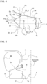
FIG. 4 is a diagram illustrating the shape of eachblade 4 of thecentrifugal fan 1 according toEmbodiment 1.FIG. 4 illustrates asuction surface 4a of theblade 4. In other words,FIG. 4 illustrates a projection of theblade 4 as theblade 4 is viewed from the rotation axis X of thecentrifugal fan 1. InEmbodiment 1, theblade 4 is three-dimensionally twisted rather than being flat.FIG. 4 conveniently illustrates theblade 4 developed on a flat surface. InFIG. 4 , only the surfaces of themain plate 2 and theshroud 5 connected to theblade 4 are schematically illustrated. - An edge of the
blade 4 located on the left ofFIG. 4 is referred to as aleading edge 6, which is a front edge in the rotation direction of thecentrifugal fan 1. An edge of theblade 4 located on the right ofFIG. 4 is referred to as a trailingedge 8, which is a rear edge in the rotation direction of thecentrifugal fan 1. Theleading edge 6 is closer to the rotation axis X of thecentrifugal fan 1 than is the trailingedge 8. The trailingedge 8 is located at an outer circumference of thecentrifugal fan 1. - With reference to
FIG. 4 , the shroud-side end 4d is joined to theshroud 5, and the main-plate-side end 4c is joined to themain plate 2. InFIG. 4 , the shroudinner surface 5a in contact with the shroud-side end 4d is shaped to fit the shroud-side end 4d of theblade 4 and is defined by a curve that gradually approaches themain plate 2 in a direction from theleading edge 6 to the trailingedge 8 of theblade 4. - As illustrated in
FIG. 4 , theleading edge 6 includesconnection part 6a, which is in proximity to the shroudinner surface 5a. Theconnection part 6a intersects the shroudinner surface 5a to form an acute angle, namely, an angle of 90 degrees or less with the shroudinner surface 5a. In other words, theleading edge 6 extends obliquely from a point P4, which is the point of intersection of theleading edge 6 and the shroudinner surface 5a, toward the trailingedge 8. - As illustrated in
FIG. 4 , theconnection part 6a of theleading edge 6 of theblade 4 connects to the shroudinner surface 5a at an acute angle formed between theconnection part 6a and the shroudinner surface 5a. Theconnection part 6a is part of arecess 6b, which curves inwardly from the leading edge. In other words, therecess 6b is located next to the point P4 and defines a valley-like shape having a bottom at a point P3_1 when therecess 6b is viewed from the center of rotation. - The
leading edge 6 extends from the point P3_1, which is the bottom of therecess 6b, to atip 6d in the rotation direction and extends from thetip 6d toward the trailingedge 8 to form aprojection 6c projecting in the rotation direction. In other words, theprojection 6c has an inverted-V shape with a peak at thetip 6d when theprojection 6c is viewed from the center of rotation. An end of theprojection 6c close to themain plate 2 is located at a point P1_1. Theleading edge 6 extends from the point P1_1 to themain plate 2 and connects to themain plate 2 at a point P0. - In other words, the
blade 4 includes theprojection 6c projecting from a reference line L3, which is a reference curve for theleading edge 6 of theblade 4, in the rotation direction at theleading edge 6. In theblade 4, theleading edge 6 extends from the point P1_1, which is located at one of opposite ends of theprojection 6c and is close to themain plate 2, to themain plate 2 in the rotation direction, and theconnection part 6a of theleading edge 6 extends from the point P3_1, which is located at the other one of the opposite ends of theprojection 6c and is close to theshroud 5, in the rotation direction. - In
Embodiment 1, the reference line L3 for theleading edge 6 is represented as a tangent passing through the point P1_1 and the point P3_1 at the opposite ends of theprojection 6c inFIG. 4 and is represented as a straight line inclined toward the trailingedge 8 in a direction from themain plate 2 toward theshroud 5. However, the reference line L3 is a curve extending along the three-dimensionally twisted shape of theactual blade 4 and passing through the points P1_1 and P3_1. The reference line L3 is not limited to such a curve. For example, the reference line L3 may be a straight line perpendicular to themain plate 2 or a straight line inclined at an angle to themain plate 2. - Or alternatively, the reference line L3 may be a curve monotonically curving in the rotation direction in a direction away from the
main plate 2, a curve monotonically curving in a direction opposite to the rotation direction in the direction away from themain plate 2, or a curve curving in a radial direction or in a direction opposite to the radial direction in the direction away from themain plate 2. -
FIG. 5 is a schematic diagram of the structure of thecentrifugal fan 1 according toEmbodiment 1 in a section containing the rotation axis X. InFIG. 5 , the shapes of thebell mouth 45 and theshroud 5 are schematically represented by lines.FIG. 5 schematically illustrates connection between thecentrifugal fan 1 and thebell mouth 45. As illustrated inFIG. 2 , thecentrifugal fan 1 is connected to theair inlet passage 51 by thebell mouth 45. Thebell mouth 45 has a shape with a decreasing diameter such that the opening gradually decreases in diameter in the direction from theair inlet passage 51 to thecentrifugal fan 1. With reference toFIG. 5 , thebell mouth 45 is connected to thecentrifugal fan 1 such that a small-diameter end 45a of thebell mouth 45 enters the central opening of theshroud 5 of thecentrifugal fan 1. - In the
heat source unit 40 according toEmbodiment 1, while thecentrifugal fan 1 is driven, part of the fluid discharged radially from thecentrifugal fan 1 passes through the space between an outer circumferential surface of thebell mouth 45 and the inner circumferential surface of the shroud and is guided to theshroud 5 of thecentrifugal fan 1. Such a flow circulating in thecasing 44 is referred to as a circulatingflow 80. The circulatingflow 80, which is a fluid that flows out of thecentrifugal fan 1 and again enters thecentrifugal fan 1 through the central opening of theshroud 5, flows at high velocity. - Collision between the circulating
flow 80, which flows at high velocity, and theleading edge 6 of eachblade 4 causes flow separation on the suction surface of theblade 4. The circulatingflow 80, which enters the space defined by theshroud 5 and thebell mouth 45 and flows in a region close to the shroudinner surface 5a, causes a stall zone to occur in a region adjacent to the shroudinner surface 5a on thesuction surface 4a of theblade 4. The stall zone on thesuction surface 4a reduces a flow rate through thecentrifugal fan 1 and the efficiency of thecentrifugal fan 1 and also causes noise. - As illustrated in
FIG. 4 , theleading edge 6 of theblade 4 has therecess 6b, which includes theconnection part 6a of theleading edge 6 at an acute angle with the shroudinner surface 5a, and theprojection 6c extending from the reference line L3 for theleading edge 6 in the rotation direction. This shape can mitigate collision between the circulatingflow 80 and theleading edge 6, so that flow separation at theleading edge 6 of theblade 4 is reduced. - The reduced flow separation results in a significant reduction in stall zone that occurs in a region adjacent to the
shroud 5 on thesuction surface 4a between theleading edge 6 of theblade 4 located close to the rotation axis X and the trailingedge 8 of theblade 4 located at the outer circumference, and noise from thecentrifugal fan 1 is thus reduced and a flow rate through thecentrifugal fan 1 is thus increased. - The trailing
edge 8 of theblade 4 of thecentrifugal fan 1 may have a linear shape parallel to the rotation axis X, a spiral shape, or a shape formed by combining multiple spiral shapes. Furthermore, the trailingedge 8 may have a set of triangular serrations like the teeth of a saw or may have a notch. - In the
centrifugal fan 1 according toEmbodiment 1, the shape of theleading edge 6 of eachblade 4 can be modified. In particular, theleading edge 6 can have a plurality ofprojections 6c. InEmbodiment 2, a modification toEmbodiment 1 is mainly described. Hereinafter, an imaginary plane parallel to themain plate 2 is defined in thecentrifugal fan 1, and a distance from the point of intersection of the imaginary plane and theleading edge 6 of theblade 4 to the point of intersection of the imaginary plane and the trailingedge 8 of theblade 4 along the suction surface is defined as a circumferential length. - The height of an opening, through which the fluid is blown out of the
centrifugal fan 1, at the outer circumference of thecentrifugal fan 1 inFIG. 4 is referred to as an outlet height. The outlet height is a distance from the periphery of themain plate 2 to the periphery of theshroud 5 at the outer circumference of thecentrifugal fan 1. Half the outlet height is a distance h. In other words, the outlet height is expressed as 2h. - As illustrated in
FIG. 4 , the point of connection between theleading edge 6 of theblade 4 and themain plate 2 is referred to as a point P0. A start point of afirst projection 6c, which is the first from themain plate 2, of theleading edge 6 is referred to as a point P1_1. A point at which theblade 4 has the longest circumferential length in the first projection, which is the first from the main plate, of theleading edge 6 is referred to as a point P2 _1. - An end point of the
first projection 6c, which is the first from themain plate 2, of theleading edge 6 is referred to as a point P3_1. The point of connection between theleading edge 6 and the shroudinner surface 5a is referred to as a point P4. As long as the reference line L3 for theleading edge 6 is parallel to the trailingedge 8 as illustrated inFIG. 4 , the point P2_1 coincides with thetip 6d of theprojection 6c. - In other words, in a case in which the
leading edge 6 includes a plurality of projections, the start point of thekth projection 6c, which is the kth from themain plate 2, is represented as a point P1_k, the peak of the kth projection is represented as a point P2_k, and the end point of thekth projection 6c is represented as a point P3_k. The point P1_k is a point that is located at one of opposite ends of thekth projection 6c of the plurality ofprojections 6c and is located close to themain plate 2. The point P3_k is a point that is located at the other one of the opposite ends of thekth projection 6c, which is the kth from themain plate 2, of the plurality of projections and is located close to theshroud 5. The point P1_k may coincide with the point P3_k-1. - A distance from the
main plate 2 to the point P1_1 along the rotation axis X of thecentrifugal fan 1 is represented as a distance fl_1, a distance from themain plate 2 to the point P2_1 along the rotation axis X of thecentrifugal fan 1 is represented as a distance f2_1, and a distance from themain plate 2 to the point P3_1 along the rotation axis X of thecentrifugal fan 1 is represented as a distance f3_1. In other words, the relationship of
fl_k < f2_k < f3_k holds in the kth projection from themain plate 2. - With reference to
FIG. 4 , the circumferential length of theblade 4 at the point P2_1 is longer than that at the point P1_1. In addition, the circumferential length of theblade 4 at the point P2_1 is longer than that at the point P3_1. This configuration reduces flow separation at theleading edge 6 of theblade 4 so that noise from thecentrifugal fan 1 is reduced and a flow rate through thecentrifugal fan 1 is increased. - Although
FIG. 4 illustrates theleading edge 6 including thesingle projection 6c which is located closer to themain plate 2 than therecess 6b in thecentrifugal fan 1 is, theleading edge 6 may include a plurality ofprojections 6c. In theleading edge 6 including a plurality ofprojections 6c, thenth projection 6c, which is the nth from themain plate 2, is set such that the circumferential length of theblade 4 at a point P2_n is longer than that at a point P1_n and is longer than that at a point P3_n. - Preferably, a point at which the
blade 4 has the longest circumferential length is located closer to theshroud 5 than a point that corresponds to half the outlet height. In other words, in a case in which theleading edge 6 includes thesingle projection 6c as illustrated inFIG. 4 , the position of the point P2_1 is set to satisfy f2_1 > h. For a plurality of projections, the position of the point P2_n on any or thenth projection 6c is set to satisfy f2_n > h. Such a configuration is effective in reducing flow separation at theleading edge 6. - In particular, for example, in the air-conditioning-apparatus
heat source unit 40 in which a pressure-loss causing object, for example, theheat exchanger 43, is located downstream of theblades 4, flow separation at theleading edge 6 of eachblade 4 is efficiently reduced. Thus, a stall zone that occurs in a shroud-side region on thesuction surface 4a between theleading edge 6 of theblade 4 to the trailingedge 8 of theblade 4 can be significantly reduced, so that noise from thecentrifugal fan 1 is reduced and a flow rate through thecentrifugal fan 1 is increased. -
FIG. 6 is a graph illustrating the relationship between the position f2_n of the point P2_n on the projection of theblade 4 and a change in input power to thecentrifugal fan 1. InFIG. 6 , the horizontal axis represents f2_n representing the position of the point P2_n, which is at the tip of the nth projection from themain plate 2, on theblade 4 and the vertical axis represents input power to thecentrifugal fan 1 under conditions where air is blown out of thecentrifugal fan 1 at a constant flow rate. Specifically, as input power to thecentrifugal fan 1 represented by the vertical axis is lower, the air can be discharged at the same flow rate with lower input power. In this state, thecentrifugal fan 1 achieves high efficiency. - As illustrated in
FIG. 6 , setting the position at which theblade 4 has the longest circumferential length to satisfy f2_n > h, which is greater than half the outlet height, can reduce input power to the centrifugal fan to improve the efficiency of the fan. - Setting the position of the point P2_n, at which the
blade 4 has the longest circumferential length, to satisfy 1.3h ≤ f2_n ≤ 1.8h can further reduce input power to thecentrifugal fan 1. The reason is as follows. If the point P2_n, at which the circumferential length of theblade 4 is long, was located at a higher level than the height of the trailingedge 8, the distance between theleading edge 6 of eachblade 4 and thenext blade 4 would decrease, and pressure loss between theblades 4 would thus increase. - However, locating the point P2_n, at which the
blade 4 has the longest circumferential length, between a level corresponding to half the height of the trailingedge 8 and an upper end of the trailingedge 8 as described above can improve the efficiency of thecentrifugal fan 1. Furthermore, the circumferential length of theblade 4 at the point P2_n on theprojection 6c is preferably set to 1.1 to 2.0 times the circumferential length of theblade 4 at the point P0 on themain plate 2. - The efficiency of the
centrifugal fan 1 according toEmbodiment 1 can be further improved by setting the position of theprojection 6c of theleading edge 6 of eachblade 4 to satisfy the following condition. InEmbodiment 3, a modification toEmbodiment 1 is mainly described. - In
Embodiment 3, in a case in which theleading edge 6 of eachblade 4 includes asingle projection 6c, theprojection 6c is located such that the distance between themain plate 2 and the point P1_1 at one of the opposite ends of theprojection 6c satisfies
"0.05 × 2h ≤ f1_1 ≤ 0.2 × 2h" and the distance between themain plate 2 and the point P3_1 at the other one of the opposite ends of theprojection 6c satisfies "0.8 × 2h ≤ f3_1 ≤ 1.3 × 2h". Such a configuration allows therecess 6b to be located in a flow boundary layer that is generated along the shroudinner surface 5a by the circulatingflow 80 illustrated inFIG. 5 , and collision between the circulatingflow 80 and theleading edge 6 is thus mitigated. - Even if the number of
projections 6c included in theleading edge 6 of eachblade 4 is one, flow separation at theleading edge 6 can therefore be effectively reduced, and a flow rate through thecentrifugal fan 1 is thus increased. The point P3_1, which is located at the end of theprojection 6c close to theshroud 5, coincides with the bottom of therecess 6b. The point P3_1 also represents a position where therecess 6b is located. - Furthermore, the point P3_1 on the
leading edge 6 may be located between the shroudinner surface 5a and a plane offset from the shroudinner surface 5a by 0.3h toward themain plate 2 along the rotation axis X. Such a configuration allows therecess 6b to be located in a flow boundary layer that is generated along the shroudinner surface 5a by the circulatingflow 80. This configuration can thus more effectively reduce flow separation at theleading edge 6 of eachblade 4 to improve the efficiency of thecentrifugal fan 1. - Furthermore, the
recess 6b may be located at a level higher than or equal to the upper end of the trailingedge 8. In other words, the point P3_1 may satisfy a condition of "2h ≤ f3_1". In this case, it is difficult to locate the bottom of therecess 6b closer to the trailingedge 8. - The efficiency of the
centrifugal fan 1 according toEmbodiment 1 can be further improved by setting the shape of part of theprojection 6c of theleading edge 6 of eachblade 4 that is close to theshroud 5 to satisfy the following condition. InEmbodiment 4, a modification toEmbodiment 1 is mainly described. - As illustrated in
FIG. 4 , when theleading edge 6 of theblade 4 of thecentrifugal fan 1 is radially projected, theprojection 6c of theleading edge 6 preferably has a shape defined by a smooth curve such that a change in shape increases between the points P2_n and P3_n. Specifically, theleading edge 6 provides a large change in circumferential length between the points P2_n and P3_n in a direction toward theshroud 5 along the rotation axis X. On theleading edge 6 of eachblade 4 of thecentrifugal fan 1, the circulatingflow 80 increases flow velocity at a position close to the shroudinner surface 5a. - However, the above-described
leading edge 6 of eachblade 4 included in thecentrifugal fan 1 allows air to flow along theblade 4 even in a region adjacent to theshroud 5 that is significantly affected by the circulatingflow 80. This configuration reduces flow separation in the region adjacent to theshroud 5 on thesuction surface 4a of theblade 4 and increases a flow rate through thecentrifugal fan 1. - The efficiency of the
centrifugal fan 1 according toEmbodiment 1 can be improved by shaping part of theprojection 6c of theleading edge 6 of eachblade 4 that is close to theshroud 5 in the following manner. InEmbodiment 5, a modification toEmbodiment 1 is mainly described. - As illustrated in
FIG. 4 , when theleading edge 6 of theblade 4 of thecentrifugal fan 1 is radially projected, part of theprojection 6c of theleading edge 6 that is located between P2_n and P3_n can have a shape including a sinusoidal shape corresponding to at least half a cycle of a sine curve or a shape similar to a sine curve. In thecentrifugal fan 1, the circulatingflow 80 increases flow velocity in a region close to the shroudinner surface 5a on thesuction surface 4a of theleading edge 6 of eachblade 4. However, the above-described shape of theleading edge 6 allows thesuction surface 4a of theleading edge 6 of eachblade 4 to fit a flow even in a region adjacent to theshroud 5 that is significantly affected by the circulatingflow 80, and flow separation is thus effectively reduced. - In a case in which the
shroud 5 of thecentrifugal fan 1 is not rotated, the circulatingflow 80 flowing between thebell mouth 45 and theshroud 5 along the rotation axis behaves like a Poiseuille flow, and the flow velocity distribution of the flow two-dimensionally changes in a section containing the rotation axis X. However, as theshroud 5 is rotated actually, the fluid flowing between theshroud 5 and thebell mouth 45 changes in circumferential component of its flow velocity. In other words, the fluid flowing along theshroud 5 behaves like a Couette flow, and its radial velocity component is higher toward the outer circumference of thecentrifugal fan 1. - The flow velocity of the fluid is determined by combining a circumferential velocity component and an axial velocity component of the fluid. For the flow between the
shroud 5 and thebell mouth 45, therefore, part of the flow that is adjacent to theshroud 5 flows at higher velocity and part of the flow that is adjacent to thebell mouth 45 flows at lower velocity. For the fluid flowing through thecentrifugal fan 1, therefore, a change in flow velocity in a region adjacent to the shroud (on an outside-diameter region) is smaller than that in a region adjacent to the bell mouth 45 (on an inside-diameter region). - The degree of turbulence of a flow depends on the velocity of the flow. It is therefore preferred that the shape of each
blade 4 be changed to match a change in flow velocity. Specifically, the shape of theblade 4 is effectively changed such that a change in shape decreases toward theshroud 5 and increases away from theshroud 5. InEmbodiment 5, theleading edge 6 of eachblade 4 has, for example, a shape of a sine curve or a shape similar to a sine curve. The shape of theleading edge 6 is not limited to these examples. - For the
centrifugal fan 1 according toEmbodiment 1, part of theprojection 6c of theleading edge 6 of eachblade 4 that is close to theshroud 5 can be set to satisfy the following condition. InEmbodiment 6, a modification toEmbodiment 1 is mainly described. - As illustrated in
FIG. 4 , when theleading edge 6 of theblade 4 of thecentrifugal fan 1 is radially projected, thenth projection 6c, which is the nth from themain plate 2, of theleading edge 6 has the longest circumferential length between the points P1_n and P2_n.
In a configuration in which theleading edge 6 includes a plurality ofprojections 6c, the circumferential length of theprojection 6c located close to theshroud 5 is set to be longer than that located close to themain plate 2. Theprojections 6c are connected by a smooth curve, and a flow rate through thecentrifugal fan 1 is thus increased. - For the
centrifugal fan 1 according toEmbodiment 1, an angle formed by theconnection part 6a of theleading edge 6 of eachblade 4 and theshroud 5 can be changed. In Embodiment 7, a modification toEmbodiment 1 is mainly described. -
FIG. 7 is an enlarged view illustrating theconnection part 6a of theblade 4 of thecentrifugal fan 1 inFIG. 4 and its surroundings. Specifically,FIG. 7 illustrates details of theconnection part 6a located between therecess 6b of theblade 4 of thecentrifugal fan 1 and the shroudinner surface 5a. As illustrated inFIG. 7 , the point of intersection of theblade 4 of thecentrifugal fan 1 and the shroudinner surface 5a is a point P4, θs is an angle formed by a tangent L1 to the shroudinner surface 5a and a straight line L5 passing through the point P4 and parallel to the rotation axis X on the plane illustrated inFigs. 4 and7 , and θb is an angle formed by the tangent L1 to the shroudinner surface 5a and a tangent L2 to theleading edge 6 of theblade 4 that passes through the point P4 on the plane illustrated inFigs. 4 and7 . - The shape of the
connection part 6a of theleading edge 6 that extends to theshroud 5 is preferably set to satisfy 0 degrees ≤ θb < θs. The shape of theleading edge 6 of theblade 4 set as described above can reduce flow separation caused by collision between the circulatingflow 80 flowing from the shroudinner surface 5a and theleading edge 6 of theblade 4. As a stall zone caused by flow separation on thesuction surface 4a of theblade 4 is thus reduced, a flow rate through thecentrifugal fan 1 is increased and the efficiency of the fan is improved. - Although
FIG. 7 illustrates the single point P4, multiple sections can be set in the circumferential direction, and the shape of theblade 4 that extends to theshroud 5 can be set to satisfy 0 degrees ≤ θb < θs in any of the set sections. As the effect of reducing flow separation is thus enhanced, the efficiency of the fan is improved. -
FIG. 8 is a graph illustrating a change in input power to thecentrifugal fan 1 associated with a change in angle θb and a change in angle θs in thecentrifugal fan 1. The horizontal axis represents a change in θb - θs and the vertical axis represents a change in input power to thecentrifugal fan 1 under conditions where the fluid flows through thecentrifugal fan 1 at a constant flow rate.FIG. 8 demonstrates that as input power to thecentrifugal fan 1 represented by the vertical axis is lower, the fluid can be discharged at the same flow rate with lower input power. A lower value on the vertical axis represents higher efficiency of thecentrifugal fan 1. - In
FIG. 8 , θb - θs ≥ 0 represents that part of theleading edge 6 that is connected to the shroudinner surface 5a has norecess 6b, and θb - θs < 0 represents that part of theleading edge 6 that is connected to the shroudinner surface 5a has arecess 6b. As illustrated inFIG. 8 , setting thecentrifugal fan 1 to satisfy θb - θs < 0, that is, 0 degrees ≤ θb < θs can reduce input power to thecentrifugal fan 1 to improve the efficiency of thecentrifugal fan 1. - The angle formed by the
connection part 6a of theleading edge 6 of eachblade 4 and theshroud 5 in thecentrifugal fan 1 according toEmbodiment 1 can be changed. InEmbodiment 8, a modification to Embodiment 7 is mainly described. - Although the angles θb and θs are set to satisfy 0 degrees ≤ θb < θs in Embodiment 7 described above, setting the angles θb and θs to satisfy 0 degrees ≤ θb < θs/2 can further enhance the effect of reducing flow separation on the
suction surface 4a. As illustrated inFIG. 8 , setting the angles θb and θs to satisfy θb - θs < -θs/2 reduces input power to the centrifugal fan represented by the vertical axis. In other words, setting the angles θb and θs to satisfy 0 degrees ≤ θb < θs/2 can further reduce flow separation at theleading edge 6 of eachblade 4, and input power to thecentrifugal fan 1 is thus further reduced. The efficiency of thecentrifugal fan 1 is thus improved. - The efficiency of the
centrifugal fan 1 according toEmbodiment 1 can be improved by further specifying the angle formed by theconnection part 6a of theleading edge 6 of eachblade 4 and theshroud 5. In Embodiment 9, a modification toEmbodiment 8 is mainly described. - For the
leading edge 6 of eachblade 4, setting the angle θs to satisfy 0 degrees ≤ θs < 60 degrees can enhance the effect of reducing flow separation at theleading edge 6 of theblade 4. The fluid flowing through thecentrifugal fan 1 passes theshroud 5, theleading edge 6 of eachblade 4, the surface of theblade 4, and the trailingedge 8 of theblade 4, and is then discharged from thecentrifugal fan 1. An air passage defined by the shroudinner surface 5a, themain plate 2, and thehub 3 decreases in cross-sectional area in a downstream direction, and the fluid passing through thecentrifugal fan 1 is thus caused to flow at a higher velocity as the fluid moves downstream. - As the fluid moves downward, the degree of turbulence of the flow through the
centrifugal fan 1 therefore decreases. Collision between theleading edge 6 and the flow of the fluid at a position with a higher degree of turbulence of the flow increases a likelihood of separation of the flow from the blade surface. - Collision between the
leading edge 6 and the flow of the fluid at a position with a lower degree of turbulence of the flow therefore reduces the likelihood of separation of the flow from the blade surface. In other words, as therecess 6b of theleading edge 6 of theblade 4 causes the fluid to collide with theleading edge 6 on the outside-diameter region of thecentrifugal fan 1, the effect of reducing flow separation is further enhanced. - The effect of reducing flow separation can therefore be further enhanced by connecting the
leading edge 6 of theblade 4 at a position where the angle θs, which is the angle formed by the tangent to the shroudinner surface 5a, satisfies 0 degrees ≤ θs < 60 degrees. If θs was greater than or equal to 60 degrees, theblade 4 would have a smaller length and would not work on the fluid, so that the effect of improving the efficiency of thecentrifugal fan 1 would be reduced. - The efficiency of the
centrifugal fan 1 according toEmbodiment 1 can be improved by further specifying an angle formed by thesuction surface 4a of eachblade 4 and the shroudinner surface 5a in a section containing the rotation axis X of thecentrifugal fan 1. -
FIG. 9 is a plan view of thecentrifugal fan 1 ofFIG. 1 as thecentrifugal fan 1 is viewed from the position where theshroud 5 is located.FIG. 10 is a diagram illustrating a section of thecentrifugal fan 1 ofFIG. 1 that contains the rotation axis X.FIG. 10 illustrates a section of part A-A inFIG. 9 . As illustrated inFIG. 10 , in the section A-A, a line representing thesuction surface 4a of theblade 4 of thecentrifugal fan 1 is a cutting-plane line 4e, and the point of intersection of the cutting-plane line 4e and the shroudinner surface 5a is a point Q. - Furthermore, in the section A-A, an angle formed by a tangent L6 to the shroud
inner surface 5a and a straight line L7 passing through the point Q and parallel to the rotation axis X is an angle θq, and an angle formed by the tangent L6 to the shroudinner surface 5a and a tangent L8 to the cutting-plane line 4e of theblade 4 and passing through the point Q is an angle θh. - The
suction surface 4a of theblade 4 and the shroudinner surface 5a can be set such that the relationship between the angles θq and θh satisfies 0 degrees ≤ θh < θq. Such a configuration reduces flow separation caused by collision of the circulatingflow 80 flowing to the shroudinner surface 5a with thesuction surface 4a of theblade 4, and a stall zone caused by flow separation on thesuction surface 4a of theblade 4 is thus reduced. This configuration leads to an increased flow rate through thecentrifugal fan 1 to improve the efficiency of thecentrifugal fan 1. - When the part A-A is set at any position in the circumferential direction, and the shape of the
blade 4 and that of theshroud 5 are set such that the above-described relationship of 0 degrees ≤ θh < θq holds in any of the set sections, separation of part of the flow that passes the shroudinner surface 5a and flows to thesuction surface 4a of theblade 4 is reduced. As a flow rate through thecentrifugal fan 1 is thus increased, the efficiency of thecentrifugal fan 1 is improved and noise generated by flow separation is reduced. -
FIG. 11 is a graph illustrating a change in input power to thecentrifugal fan 1 associated with a change in angle θq and a change in angle θh in thecentrifugal fan 1. The horizontal axis represents a change in θh - θq and the vertical axis represents a change in input power to thecentrifugal fan 1 under conditions where the fluid flows through thecentrifugal fan 1 at a constant flow rate. As illustrated inFIG. 11 , setting θh - θq < 0, that is,
0 degrees ≤ θh < θq can reduce input power to thecentrifugal fan 1 to improve the efficiency of thecentrifugal fan 1. - As illustrated in
FIG. 10 , the thickness of theblade 4 is not necessarily constant in a section of thecentrifugal fan 1 that contains the rotation axis X. In other words, the shape of apressure surface 4b of theblade 4 can be appropriately set irrespective of the shape of thesuction surface 4a of theblade 4. - The
centrifugal fan 1 is not limited to the above-described embodiments. The efficiency of thecentrifugal fan 1 can be further improved by further specifying the relationship between the angles θh and θq in Embodiment 10. Although 0 degrees ≤ θh < θq in Embodiment 10 is described above, setting θq/2 ≤ θh < θq further reduces input power to thecentrifugal fan 1 to improve the efficiency of thecentrifugal fan 1. - As illustrated in
FIG. 11 , setting -θq/2 ≤ θh - θq < 0, that is, setting the angle θh to satisfy θq/2 ≤ θh < θq can further reduce input power to thecentrifugal fan 1 to improve the efficiency of thecentrifugal fan 1. If the shape of thesuction surface 4a of eachblade 4 was set to satisfy 0 ≤ θh - θq < θq/2, that is, if the angle θh was set to satisfy 0 ≤ θh < 3θq/2, flow separation on thesuction surface 4a of theblade 4 would be reduced, and the flow rate would also be reduced because of a reduction in force applied from theblade 4 to the fluid. - The reason is that the effect of reducing the flow rate is greater than the effect of reducing flow separation when these effects are compared with each other under the same flow rate condition in the
centrifugal fan 1. Setting θq/2 ≤ θh < θq therefore allows the effect of reducing flow separation to be greater than the effect of reducing the flow rate, and input power to thecentrifugal fan 1 is thus reduced. The efficiency of thecentrifugal fan 1 is thus improved. - The
centrifugal fan 1 can be included not only in theheat source unit 40 of the air-conditioning apparatus described inEmbodiment 1 but also in other units and apparatuses. In Embodiment 12, an air-conditioning-apparatusindoor unit 53 including thecentrifugal fan 1 is described as an example. -
FIG. 12 is a sectional view illustrating the structure of the air-conditioning-apparatusindoor unit 53 including thecentrifugal fan 1. As illustrated inFIG. 12 , theindoor unit 53 includes at least oneheat exchanger 43, acompressor 41, acontrol box 42, thecentrifugal fan 1, abell mouth 45, afan motor 50, and adrain pan 47. Theheat exchanger 43, thecompressor 41, thecontrol box 42, thecentrifugal fan 1, thebell mouth 45, thefan motor 50, and thedrain pan 47 are arranged in acasing 44, which is the shell of theindoor unit 53. - The
casing 44 has anair inlet 46 and anair outlet 48. Theair inlet 46 and theair outlet 48 are opened to provide communication between the inside and the outside of thecasing 44. Theair outlet 48 is opened in, for example, the same surface of thecasing 44 as that in which theair inlet 46 is opened. In other words, theindoor unit 53 suctions air and blows air through a lower surface or an upper surface of thecasing 44. The air is suctioned into and blown out of thecasing 44 through the same surface of thecasing 44. With reference toFIG. 12 , theair inlet 46 is opened at a central portion of the lower surface of thecasing 44 and theair outlet 48 is opened around theair inlet 46 in Embodiment 12. - The
heat exchanger 43 is disposed between thecentrifugal fan 1 and theair outlet 48 and is disposed downstream of thecentrifugal fan 1. Thecentrifugal fan 1 has the rotation axis X and rotates about the rotation axis X to send a fluid. Thecentrifugal fan 1 is driven to rotate by thefan motor 50. Thebell mouth 45 is disposed at part of thecentrifugal fan 1 through which a fluid is suctioned and guides the fluid flowing through anair inlet passage 51 to thecentrifugal fan 1. Thebell mouth 45 includes a portion having an opening that gradually decreases in diameter in a direction from its inlet adjacent to theair inlet passage 51 toward thecentrifugal fan 1. Thedrain pan 47 is disposed under theheat exchanger 43. - The
casing 44 has theair inlet passage 51 and anair outlet passage 52, which are divided by a partition, in thecasing 44. Theair inlet passage 51 is located in lower part of thecasing 44 and communicates with theair inlet 46 to guide the air suctioned through theair inlet 46 to thebell mouth 45. Theair outlet passage 52 is located in upper part of thecasing 44 and communicates with theair outlet 48 to guide the fluid blown out of thecentrifugal fan 1 to theair outlet 48. - As described above, as the air-conditioning-apparatus
indoor unit 53 includes thecentrifugal fan 1, the air-conditioning-apparatusindoor unit 53 achieves improved fan efficiency to improve operation efficiency. -
- 1
- centrifugal fan
- 2
- main plate
- 3
- hub
- 3a
- hole
- 4
- blade
- 4a
- suction surface
- 4b
- pressure surface
- 4c
- main-plate-side end
- 4d
- shroud-side end
- 4e
- cutting-plane line
- 5
- shroud
- 5a
- shroud inner surface
- 5b
- shroud outer surface
- 5c
- protrusion
- 5d
- outer circumferential face
- 6
- leading edge
- 6a
- connection part
- 6b
- recess
- 6c
- projection
- 6d
- tip
- 8
- trailing edge
- 40
- heat source unit
- 41
- compressor
- 42
- control box
- 43
- heat exchanger
- 44
- casing
- 45
- bell mouth
- 45a
- end
- 46
- air inlet
- 47
- drain pan
- 48
- air outlet
- 49
- air passage partition
- 50
- fan motor
- 51
- air inlet passage
- 52
- air outlet passage
- 53
- indoor unit
- 80
- circulating flow
- L1
- tangent
- L2
- tangent
- L3
- reference line
- L6
- tangent
- L7
- straight line
- L8
- tangent
- O
- center
- X
- rotation axis
- θb
- angle
- θh
- angle
- θq
- angle
- θs
- angle
Claims (11)
- A centrifugal fan (1) comprising:- a main plate (2);- a blade (4) connected to the main plate (2); and- a shroud (5) having an annular shape and connected to a shroud-side end (4d) of the blade (4) that is an end opposite a main-plate-side end (4c) of the blade (4) connected to the main plate (2),the centrifugal fan (1) being configured to rotate about a rotation axis (X) to suction a fluid through an opening of the shroud (5) and discharge the fluid through the blade (4) in a radial direction,the blade (4) having- a leading edge (6) that is an edge of the blade (4) located forward in a rotation direction, and- a trailing edge (8) that is an edge opposite the leading edge (6) and is located farther from the rotation axis (X) than is the leading edge (6),a length of the blade (4) from the leading edge (6) to the trailing edge (8) in a section parallel to the main plate (2) being a circumferential length, a distance between a peripheral edge of the main plate (2) and a peripheral edge of the shroud (5) being an outlet height, part of the blade (4) that has a longest circumferential length being located closer to the shroud (5) than is a middle of the outlet height,the leading edge (6) including- a recess (6b) located next to a point P4 at which a shroud inner surface (5a) of the shroud (5) that faces the main plate (2) is connected to the leading edge(6), the recess (6b) including connection part (6a) extending from the point P4 toward the trailing edge(8) and defining a valley-like shape having a bottom when the recess (6b) is viewed from the rotation axis (X), and- a projection (6c) which is located closer to the main plate (2) than the recess(6b) is, the projection (6c) projecting in the rotation direction and having an inverted-V shape with a peak when the projection (6c) is viewed from the rotation axis (X),the outlet height being 2h, a point that is one of opposite ends of the projection (6c) and is located close to the main plate (2) being a point P1_1, a point that is an other one of the opposite ends and is located close to the shroud (5) being a point P3_1, a distance f1_1 between the point P1_1 and the main plate (2) being set to satisfy 0.05 × 2h ≤ f1_1 ≤ 0.2 × 2h,a distance f3_1 between the point P3_1 and the main plate (2) being set to satisfy 0.8 × 2h ≤ f3_1 ≤ 1.3 × 2h.
- The centrifugal fan (1) of claim 1,
wherein a tangent L1 to the shroud inner surface at the point P4 and a tangent L2 to the leading edge (6) at the point P4 form an angle of 90 degrees or less. - The centrifugal fan (1) of claim 2,
wherein an angle θs formed by the tangent L1 and a straight line L5 parallel to the rotation axis (X) and an angle θb formed by the tangent L1 and the tangent L2 to the leading edge (6) at the point P4 are set to satisfy 0 degrees ≤ θb < θs. - The centrifugal fan of claim 3,
wherein the angle θs and the angle θb are set to satisfy 0 degrees ≤ θb < θs/2. - The centrifugal fan of claim 3 or 4,
wherein the angle θs is set to satisfy 0 degrees ≤ θs < 60 degrees. - The centrifugal fan of any one of claims 1 to 5,
wherein a point on the leading edge (6) of the part having the longest circumferential length is a point P2_1, and a change in circumferential length between the points P2_1 and P3_1 associated with a change in distance in a direction along the rotation axis (X) is greater than a change in circumferential length between the points P1_1 and P2_1 associated with a change in distance in the direction along the rotation axis (X). - The centrifugal fan of any one of claims 1 to6,
wherein the projection (6c) is smoothly continuous with the recess. - The centrifugal fan of claim7,
wherein the leading edge (6) has a shape including a sinusoidal shape corresponding to at least half a cycle of a sine curve when the leading edge (6) is projected in a radial direction. - The centrifugal fan of any one of claims 1 to8,
wherein a point at which the shroud (5) inner surface is connected to a suction surface (4a) of the blade (4) that faces the rotation axis (X) in a section containing the rotation axis (X) is a point Q, an angle formed at the point Q between a tangent L6 to the shroud (5) inner surface and a line parallel to the rotation axis (X) is an angle θq, an angle formed between the tangent L6 and a tangent L8 to the suction surface (4a) at the Q is an angle θh, and the angle θh is set to satisfy 0 degrees ≤ θh < θq. - An air-conditioning apparatuscomprising a heat source unit (40) and a load-side unit,at least one of the heat source unit (40) and the load-side unit including the centrifugal fan (1) of any one of claims 1 to9.
- The air-conditioning apparatus of claim 10,wherein the heat source unit (40) includes a heat exchanger (43) and the centrifugal fan (1) in a casing (44),wherein the casing (44) includes a panel removable from a side face of the casing (44), andwherein the side face with the panel removed is used as an air inlet or an air outlet of the heat source unit (40).
Applications Claiming Priority (1)
| Application Number | Priority Date | Filing Date | Title |
|---|---|---|---|
| PCT/JP2018/045896 WO2020121484A1 (en) | 2018-12-13 | 2018-12-13 | Centrifugal fan and air conditioner |
Publications (3)
| Publication Number | Publication Date |
|---|---|
| EP3896290A1 EP3896290A1 (en) | 2021-10-20 |
| EP3896290A4 EP3896290A4 (en) | 2021-12-15 |
| EP3896290B1 true EP3896290B1 (en) | 2023-03-29 |
Family
ID=70682444
Family Applications (1)
| Application Number | Title | Priority Date | Filing Date |
|---|---|---|---|
| EP18943319.6A Active EP3896290B1 (en) | 2018-12-13 | 2018-12-13 | Centrifugal fan and air conditioner |
Country Status (6)
| Country | Link |
|---|---|
| US (1) | US11674520B2 (en) |
| EP (1) | EP3896290B1 (en) |
| JP (1) | JP6695509B1 (en) |
| CN (1) | CN113167289B (en) |
| ES (1) | ES2942991T3 (en) |
| WO (1) | WO2020121484A1 (en) |
Families Citing this family (2)
| Publication number | Priority date | Publication date | Assignee | Title |
|---|---|---|---|---|
| WO2022139498A1 (en) * | 2020-12-25 | 2022-06-30 | 삼성전자주식회사 | Air conditioner including centrifugal fan |
| US20220205650A1 (en) * | 2020-12-25 | 2022-06-30 | Samsung Electronics Co., Ltd. | Air conditioner including a centrifugal fan |
Family Cites Families (17)
| Publication number | Priority date | Publication date | Assignee | Title |
|---|---|---|---|---|
| JPS50157735U (en) | 1974-06-13 | 1975-12-26 | ||
| JP3391318B2 (en) * | 1999-11-16 | 2003-03-31 | ダイキン工業株式会社 | Centrifugal fan and air conditioner equipped with the fan |
| JP3978083B2 (en) * | 2001-06-12 | 2007-09-19 | 漢拏空調株式会社 | Axial fan |
| KR100820857B1 (en) * | 2003-03-05 | 2008-04-10 | 한라공조주식회사 | Axial Flow Fan |
| JP2005233057A (en) | 2004-02-19 | 2005-09-02 | Mitsubishi Heavy Ind Ltd | Compressor for transonic fluid |
| JP4663259B2 (en) * | 2004-06-18 | 2011-04-06 | 日立アプライアンス株式会社 | Blower and vacuum cleaner |
| JP2009074385A (en) | 2007-09-19 | 2009-04-09 | Ihi Corp | Centrifugal compressor |
| JP4612084B2 (en) * | 2008-08-29 | 2011-01-12 | 株式会社日立産機システム | Centrifugal fan and air fluid machine using the same |
| KR101761311B1 (en) * | 2010-09-02 | 2017-07-25 | 엘지전자 주식회사 | A turbo fan for air conditioner |
| JP2012085836A (en) | 2010-10-20 | 2012-05-10 | Panasonic Corp | Washing and drying machine |
| CN102536892A (en) * | 2012-03-10 | 2012-07-04 | 广东恒业电器有限公司 | Multi-blade centrifugal fan with reinforced air inlet function |
| JP5783214B2 (en) | 2013-09-30 | 2015-09-24 | ダイキン工業株式会社 | Centrifugal blower and air conditioner equipped with the same |
| US9523370B2 (en) * | 2014-04-07 | 2016-12-20 | Hanon Systems | Blower with curved blades |
| WO2016067409A1 (en) | 2014-10-30 | 2016-05-06 | 三菱電機株式会社 | Turbofan, and indoor unit for air conditioning device |
| JP2016121580A (en) | 2014-12-24 | 2016-07-07 | ダイキン工業株式会社 | Centrifugal blower |
| CN204828043U (en) * | 2015-08-03 | 2015-12-02 | 江森自控楼宇设备科技(无锡)有限公司 | Blade |
| JP2019127865A (en) | 2018-01-23 | 2019-08-01 | 株式会社デンソー | Centrifugal fan |
-
2018
- 2018-12-13 JP JP2019537187A patent/JP6695509B1/en active Active
- 2018-12-13 CN CN201880099721.9A patent/CN113167289B/en active Active
- 2018-12-13 US US17/287,125 patent/US11674520B2/en active Active
- 2018-12-13 WO PCT/JP2018/045896 patent/WO2020121484A1/en unknown
- 2018-12-13 ES ES18943319T patent/ES2942991T3/en active Active
- 2018-12-13 EP EP18943319.6A patent/EP3896290B1/en active Active
Also Published As
| Publication number | Publication date |
|---|---|
| ES2942991T3 (en) | 2023-06-08 |
| US20210381513A1 (en) | 2021-12-09 |
| WO2020121484A1 (en) | 2020-06-18 |
| CN113167289A (en) | 2021-07-23 |
| US11674520B2 (en) | 2023-06-13 |
| EP3896290A1 (en) | 2021-10-20 |
| CN113167289B (en) | 2023-03-24 |
| EP3896290A4 (en) | 2021-12-15 |
| JP6695509B1 (en) | 2020-05-20 |
| JPWO2020121484A1 (en) | 2021-02-15 |
Similar Documents
| Publication | Publication Date | Title |
|---|---|---|
| US9995303B2 (en) | Air conditioner | |
| EP2618066B1 (en) | Blower for outdoor unit, outdoor unit, and refrigeration cycle device | |
| JP6415741B2 (en) | Blower and air conditioner equipped with the same | |
| EP3372839B1 (en) | Blower, outdoor unit, and refrigeration cycle apparatus | |
| EP2781844B1 (en) | Turbo fan and ceiling type air conditioner using the same | |
| US10890194B2 (en) | Air-sending device and air-conditioning apparatus using the same | |
| TW201200738A (en) | Electric blower and electric vacuum cleaner with the same | |
| TW200530539A (en) | Integral air conditioner | |
| EP3896290B1 (en) | Centrifugal fan and air conditioner | |
| JP2007205268A (en) | Centrifugal fan | |
| JP2701604B2 (en) | Air conditioner | |
| KR100468468B1 (en) | An air conditioning system | |
| JP2014240633A (en) | Air blower and outdoor unit mounted with air blower | |
| KR20200037945A (en) | fan assembly | |
| JP2013053532A (en) | Axial flow blower and air conditioner | |
| JP2012002165A (en) | Turbo fan and air conditioning machine using the same | |
| CN109891101B (en) | Propeller fan, outdoor unit, and refrigeration cycle device | |
| KR100295964B1 (en) | Interior of the ceiling air conditioner | |
| JP6430032B2 (en) | Centrifugal fan, air conditioner and refrigeration cycle apparatus | |
| CN110741207A (en) | Air conditioner | |
| JP7458552B2 (en) | Air blower | |
| WO2020147751A1 (en) | Indoor unit of floor air conditioner | |
| WO2020147750A1 (en) | Vertical air conditioner indoor unit | |
| KR101871723B1 (en) | An Indoor unit and an air conditioner having it | |
| JPH0321811B2 (en) |
Legal Events
| Date | Code | Title | Description |
|---|---|---|---|
| STAA | Information on the status of an ep patent application or granted ep patent |
Free format text: STATUS: THE INTERNATIONAL PUBLICATION HAS BEEN MADE |
|
| PUAI | Public reference made under article 153(3) epc to a published international application that has entered the european phase |
Free format text: ORIGINAL CODE: 0009012 |
|
| STAA | Information on the status of an ep patent application or granted ep patent |
Free format text: STATUS: REQUEST FOR EXAMINATION WAS MADE |
|
| 17P | Request for examination filed |
Effective date: 20210609 |
|
| AK | Designated contracting states |
Kind code of ref document: A1 Designated state(s): AL AT BE BG CH CY CZ DE DK EE ES FI FR GB GR HR HU IE IS IT LI LT LU LV MC MK MT NL NO PL PT RO RS SE SI SK SM TR |
|
| A4 | Supplementary search report drawn up and despatched |
Effective date: 20211112 |
|
| RIC1 | Information provided on ipc code assigned before grant |
Ipc: F24F 1/38 20110101ALI20211108BHEP Ipc: F24F 1/0022 20190101ALI20211108BHEP Ipc: F04D 29/30 20060101AFI20211108BHEP |
|
| DAV | Request for validation of the european patent (deleted) | ||
| DAX | Request for extension of the european patent (deleted) | ||
| REG | Reference to a national code |
Ref country code: DE Ref legal event code: R079 Ref document number: 602018047934 Country of ref document: DE Free format text: PREVIOUS MAIN CLASS: F04D0029300000 Ipc: F04D0029280000 |
|
| GRAP | Despatch of communication of intention to grant a patent |
Free format text: ORIGINAL CODE: EPIDOSNIGR1 |
|
| STAA | Information on the status of an ep patent application or granted ep patent |
Free format text: STATUS: GRANT OF PATENT IS INTENDED |
|
| RIC1 | Information provided on ipc code assigned before grant |
Ipc: F24F 1/38 20110101ALI20220909BHEP Ipc: F24F 1/0022 20190101ALI20220909BHEP Ipc: F04D 29/30 20060101ALI20220909BHEP Ipc: F04D 29/28 20060101AFI20220909BHEP |
|
| INTG | Intention to grant announced |
Effective date: 20221007 |
|
| GRAS | Grant fee paid |
Free format text: ORIGINAL CODE: EPIDOSNIGR3 |
|
| GRAA | (expected) grant |
Free format text: ORIGINAL CODE: 0009210 |
|
| STAA | Information on the status of an ep patent application or granted ep patent |
Free format text: STATUS: THE PATENT HAS BEEN GRANTED |
|
| AK | Designated contracting states |
Kind code of ref document: B1 Designated state(s): AL AT BE BG CH CY CZ DE DK EE ES FI FR GB GR HR HU IE IS IT LI LT LU LV MC MK MT NL NO PL PT RO RS SE SI SK SM TR |
|
| REG | Reference to a national code |
Ref country code: CH Ref legal event code: EP |
|
| REG | Reference to a national code |
Ref country code: DE Ref legal event code: R096 Ref document number: 602018047934 Country of ref document: DE |
|
| REG | Reference to a national code |
Ref country code: AT Ref legal event code: REF Ref document number: 1556847 Country of ref document: AT Kind code of ref document: T Effective date: 20230415 |
|
| REG | Reference to a national code |
Ref country code: IE Ref legal event code: FG4D |
|
| REG | Reference to a national code |
Ref country code: ES Ref legal event code: FG2A Ref document number: 2942991 Country of ref document: ES Kind code of ref document: T3 Effective date: 20230608 |
|
| REG | Reference to a national code |
Ref country code: LT Ref legal event code: MG9D |
|
| PG25 | Lapsed in a contracting state [announced via postgrant information from national office to epo] |
Ref country code: RS Free format text: LAPSE BECAUSE OF FAILURE TO SUBMIT A TRANSLATION OF THE DESCRIPTION OR TO PAY THE FEE WITHIN THE PRESCRIBED TIME-LIMIT Effective date: 20230329 Ref country code: NO Free format text: LAPSE BECAUSE OF FAILURE TO SUBMIT A TRANSLATION OF THE DESCRIPTION OR TO PAY THE FEE WITHIN THE PRESCRIBED TIME-LIMIT Effective date: 20230629 Ref country code: LV Free format text: LAPSE BECAUSE OF FAILURE TO SUBMIT A TRANSLATION OF THE DESCRIPTION OR TO PAY THE FEE WITHIN THE PRESCRIBED TIME-LIMIT Effective date: 20230329 Ref country code: LT Free format text: LAPSE BECAUSE OF FAILURE TO SUBMIT A TRANSLATION OF THE DESCRIPTION OR TO PAY THE FEE WITHIN THE PRESCRIBED TIME-LIMIT Effective date: 20230329 Ref country code: HR Free format text: LAPSE BECAUSE OF FAILURE TO SUBMIT A TRANSLATION OF THE DESCRIPTION OR TO PAY THE FEE WITHIN THE PRESCRIBED TIME-LIMIT Effective date: 20230329 |
|
| REG | Reference to a national code |
Ref country code: NL Ref legal event code: MP Effective date: 20230329 |
|
| REG | Reference to a national code |
Ref country code: AT Ref legal event code: MK05 Ref document number: 1556847 Country of ref document: AT Kind code of ref document: T Effective date: 20230329 |
|
| P01 | Opt-out of the competence of the unified patent court (upc) registered |
Effective date: 20230711 |
|
| PG25 | Lapsed in a contracting state [announced via postgrant information from national office to epo] |
Ref country code: SE Free format text: LAPSE BECAUSE OF FAILURE TO SUBMIT A TRANSLATION OF THE DESCRIPTION OR TO PAY THE FEE WITHIN THE PRESCRIBED TIME-LIMIT Effective date: 20230329 Ref country code: NL Free format text: LAPSE BECAUSE OF FAILURE TO SUBMIT A TRANSLATION OF THE DESCRIPTION OR TO PAY THE FEE WITHIN THE PRESCRIBED TIME-LIMIT Effective date: 20230329 Ref country code: GR Free format text: LAPSE BECAUSE OF FAILURE TO SUBMIT A TRANSLATION OF THE DESCRIPTION OR TO PAY THE FEE WITHIN THE PRESCRIBED TIME-LIMIT Effective date: 20230630 Ref country code: FI Free format text: LAPSE BECAUSE OF FAILURE TO SUBMIT A TRANSLATION OF THE DESCRIPTION OR TO PAY THE FEE WITHIN THE PRESCRIBED TIME-LIMIT Effective date: 20230329 |
|
| PG25 | Lapsed in a contracting state [announced via postgrant information from national office to epo] |
Ref country code: SM Free format text: LAPSE BECAUSE OF FAILURE TO SUBMIT A TRANSLATION OF THE DESCRIPTION OR TO PAY THE FEE WITHIN THE PRESCRIBED TIME-LIMIT Effective date: 20230329 Ref country code: RO Free format text: LAPSE BECAUSE OF FAILURE TO SUBMIT A TRANSLATION OF THE DESCRIPTION OR TO PAY THE FEE WITHIN THE PRESCRIBED TIME-LIMIT Effective date: 20230329 Ref country code: PT Free format text: LAPSE BECAUSE OF FAILURE TO SUBMIT A TRANSLATION OF THE DESCRIPTION OR TO PAY THE FEE WITHIN THE PRESCRIBED TIME-LIMIT Effective date: 20230731 Ref country code: EE Free format text: LAPSE BECAUSE OF FAILURE TO SUBMIT A TRANSLATION OF THE DESCRIPTION OR TO PAY THE FEE WITHIN THE PRESCRIBED TIME-LIMIT Effective date: 20230329 Ref country code: AT Free format text: LAPSE BECAUSE OF FAILURE TO SUBMIT A TRANSLATION OF THE DESCRIPTION OR TO PAY THE FEE WITHIN THE PRESCRIBED TIME-LIMIT Effective date: 20230329 |
|
| PG25 | Lapsed in a contracting state [announced via postgrant information from national office to epo] |
Ref country code: SK Free format text: LAPSE BECAUSE OF FAILURE TO SUBMIT A TRANSLATION OF THE DESCRIPTION OR TO PAY THE FEE WITHIN THE PRESCRIBED TIME-LIMIT Effective date: 20230329 Ref country code: PL Free format text: LAPSE BECAUSE OF FAILURE TO SUBMIT A TRANSLATION OF THE DESCRIPTION OR TO PAY THE FEE WITHIN THE PRESCRIBED TIME-LIMIT Effective date: 20230329 Ref country code: IS Free format text: LAPSE BECAUSE OF FAILURE TO SUBMIT A TRANSLATION OF THE DESCRIPTION OR TO PAY THE FEE WITHIN THE PRESCRIBED TIME-LIMIT Effective date: 20230729 |
|
| REG | Reference to a national code |
Ref country code: DE Ref legal event code: R097 Ref document number: 602018047934 Country of ref document: DE |
|
| PGFP | Annual fee paid to national office [announced via postgrant information from national office to epo] |
Ref country code: GB Payment date: 20231102 Year of fee payment: 6 |
|
| PG25 | Lapsed in a contracting state [announced via postgrant information from national office to epo] |
Ref country code: DK Free format text: LAPSE BECAUSE OF FAILURE TO SUBMIT A TRANSLATION OF THE DESCRIPTION OR TO PAY THE FEE WITHIN THE PRESCRIBED TIME-LIMIT Effective date: 20230329 Ref country code: CZ Free format text: LAPSE BECAUSE OF FAILURE TO SUBMIT A TRANSLATION OF THE DESCRIPTION OR TO PAY THE FEE WITHIN THE PRESCRIBED TIME-LIMIT Effective date: 20230329 |
|
| PGFP | Annual fee paid to national office [announced via postgrant information from national office to epo] |
Ref country code: DE Payment date: 20231031 Year of fee payment: 6 |
|
| PLBE | No opposition filed within time limit |
Free format text: ORIGINAL CODE: 0009261 |
|
| STAA | Information on the status of an ep patent application or granted ep patent |
Free format text: STATUS: NO OPPOSITION FILED WITHIN TIME LIMIT |
|
| 26N | No opposition filed |
Effective date: 20240103 |