EP3890876B1 - Lateral loading of microcapillary arrays - Google Patents
Lateral loading of microcapillary arrays Download PDFInfo
- Publication number
- EP3890876B1 EP3890876B1 EP19892332.8A EP19892332A EP3890876B1 EP 3890876 B1 EP3890876 B1 EP 3890876B1 EP 19892332 A EP19892332 A EP 19892332A EP 3890876 B1 EP3890876 B1 EP 3890876B1
- Authority
- EP
- European Patent Office
- Prior art keywords
- fluid
- microcapillary
- flow cell
- distribution
- wells
- Prior art date
- Legal status (The legal status is an assumption and is not a legal conclusion. Google has not performed a legal analysis and makes no representation as to the accuracy of the status listed.)
- Active
Links
Images










Classifications
-
- B—PERFORMING OPERATIONS; TRANSPORTING
- B01—PHYSICAL OR CHEMICAL PROCESSES OR APPARATUS IN GENERAL
- B01L—CHEMICAL OR PHYSICAL LABORATORY APPARATUS FOR GENERAL USE
- B01L3/00—Containers or dishes for laboratory use, e.g. laboratory glassware; Droppers
- B01L3/50—Containers for the purpose of retaining a material to be analysed, e.g. test tubes
- B01L3/502—Containers for the purpose of retaining a material to be analysed, e.g. test tubes with fluid transport, e.g. in multi-compartment structures
- B01L3/5027—Containers for the purpose of retaining a material to be analysed, e.g. test tubes with fluid transport, e.g. in multi-compartment structures by integrated microfluidic structures, i.e. dimensions of channels and chambers are such that surface tension forces are important, e.g. lab-on-a-chip
- B01L3/502746—Containers for the purpose of retaining a material to be analysed, e.g. test tubes with fluid transport, e.g. in multi-compartment structures by integrated microfluidic structures, i.e. dimensions of channels and chambers are such that surface tension forces are important, e.g. lab-on-a-chip characterised by the means for controlling flow resistance, e.g. flow controllers, baffles or throttle valves
-
- B—PERFORMING OPERATIONS; TRANSPORTING
- B01—PHYSICAL OR CHEMICAL PROCESSES OR APPARATUS IN GENERAL
- B01L—CHEMICAL OR PHYSICAL LABORATORY APPARATUS FOR GENERAL USE
- B01L3/00—Containers or dishes for laboratory use, e.g. laboratory glassware; Droppers
- B01L3/50—Containers for the purpose of retaining a material to be analysed, e.g. test tubes
- B01L3/502—Containers for the purpose of retaining a material to be analysed, e.g. test tubes with fluid transport, e.g. in multi-compartment structures
- B01L3/5027—Containers for the purpose of retaining a material to be analysed, e.g. test tubes with fluid transport, e.g. in multi-compartment structures by integrated microfluidic structures, i.e. dimensions of channels and chambers are such that surface tension forces are important, e.g. lab-on-a-chip
- B01L3/502715—Containers for the purpose of retaining a material to be analysed, e.g. test tubes with fluid transport, e.g. in multi-compartment structures by integrated microfluidic structures, i.e. dimensions of channels and chambers are such that surface tension forces are important, e.g. lab-on-a-chip characterised by interfacing components, e.g. fluidic, electrical, optical or mechanical interfaces
-
- B—PERFORMING OPERATIONS; TRANSPORTING
- B01—PHYSICAL OR CHEMICAL PROCESSES OR APPARATUS IN GENERAL
- B01L—CHEMICAL OR PHYSICAL LABORATORY APPARATUS FOR GENERAL USE
- B01L3/00—Containers or dishes for laboratory use, e.g. laboratory glassware; Droppers
- B01L3/50—Containers for the purpose of retaining a material to be analysed, e.g. test tubes
- B01L3/502—Containers for the purpose of retaining a material to be analysed, e.g. test tubes with fluid transport, e.g. in multi-compartment structures
- B01L3/5027—Containers for the purpose of retaining a material to be analysed, e.g. test tubes with fluid transport, e.g. in multi-compartment structures by integrated microfluidic structures, i.e. dimensions of channels and chambers are such that surface tension forces are important, e.g. lab-on-a-chip
- B01L3/50273—Containers for the purpose of retaining a material to be analysed, e.g. test tubes with fluid transport, e.g. in multi-compartment structures by integrated microfluidic structures, i.e. dimensions of channels and chambers are such that surface tension forces are important, e.g. lab-on-a-chip characterised by the means or forces applied to move the fluids
-
- B—PERFORMING OPERATIONS; TRANSPORTING
- B01—PHYSICAL OR CHEMICAL PROCESSES OR APPARATUS IN GENERAL
- B01L—CHEMICAL OR PHYSICAL LABORATORY APPARATUS FOR GENERAL USE
- B01L3/00—Containers or dishes for laboratory use, e.g. laboratory glassware; Droppers
- B01L3/50—Containers for the purpose of retaining a material to be analysed, e.g. test tubes
- B01L3/508—Rigid containers without fluid transport within
- B01L3/5085—Rigid containers without fluid transport within for multiple samples, e.g. microtitration plates
- B01L3/50857—Rigid containers without fluid transport within for multiple samples, e.g. microtitration plates using arrays or bundles of open capillaries for holding samples
-
- B—PERFORMING OPERATIONS; TRANSPORTING
- B01—PHYSICAL OR CHEMICAL PROCESSES OR APPARATUS IN GENERAL
- B01L—CHEMICAL OR PHYSICAL LABORATORY APPARATUS FOR GENERAL USE
- B01L9/00—Supporting devices; Holding devices
- B01L9/52—Supports specially adapted for flat sample carriers, e.g. for plates, slides, chips
-
- G—PHYSICS
- G01—MEASURING; TESTING
- G01N—INVESTIGATING OR ANALYSING MATERIALS BY DETERMINING THEIR CHEMICAL OR PHYSICAL PROPERTIES
- G01N21/00—Investigating or analysing materials by the use of optical means, i.e. using sub-millimetre waves, infrared, visible or ultraviolet light
- G01N21/62—Systems in which the material investigated is excited whereby it emits light or causes a change in wavelength of the incident light
- G01N21/63—Systems in which the material investigated is excited whereby it emits light or causes a change in wavelength of the incident light optically excited
- G01N21/64—Fluorescence; Phosphorescence
- G01N21/6428—Measuring fluorescence of fluorescent products of reactions or of fluorochrome labelled reactive substances, e.g. measuring quenching effects, using measuring "optrodes"
-
- B—PERFORMING OPERATIONS; TRANSPORTING
- B01—PHYSICAL OR CHEMICAL PROCESSES OR APPARATUS IN GENERAL
- B01L—CHEMICAL OR PHYSICAL LABORATORY APPARATUS FOR GENERAL USE
- B01L2200/00—Solutions for specific problems relating to chemical or physical laboratory apparatus
- B01L2200/06—Fluid handling related problems
- B01L2200/0684—Venting, avoiding backpressure, avoid gas bubbles
-
- B—PERFORMING OPERATIONS; TRANSPORTING
- B01—PHYSICAL OR CHEMICAL PROCESSES OR APPARATUS IN GENERAL
- B01L—CHEMICAL OR PHYSICAL LABORATORY APPARATUS FOR GENERAL USE
- B01L2200/00—Solutions for specific problems relating to chemical or physical laboratory apparatus
- B01L2200/16—Reagents, handling or storing thereof
-
- B—PERFORMING OPERATIONS; TRANSPORTING
- B01—PHYSICAL OR CHEMICAL PROCESSES OR APPARATUS IN GENERAL
- B01L—CHEMICAL OR PHYSICAL LABORATORY APPARATUS FOR GENERAL USE
- B01L2300/00—Additional constructional details
- B01L2300/04—Closures and closing means
- B01L2300/041—Connecting closures to device or container
-
- B—PERFORMING OPERATIONS; TRANSPORTING
- B01—PHYSICAL OR CHEMICAL PROCESSES OR APPARATUS IN GENERAL
- B01L—CHEMICAL OR PHYSICAL LABORATORY APPARATUS FOR GENERAL USE
- B01L2300/00—Additional constructional details
- B01L2300/04—Closures and closing means
- B01L2300/046—Function or devices integrated in the closure
- B01L2300/048—Function or devices integrated in the closure enabling gas exchange, e.g. vents
-
- B—PERFORMING OPERATIONS; TRANSPORTING
- B01—PHYSICAL OR CHEMICAL PROCESSES OR APPARATUS IN GENERAL
- B01L—CHEMICAL OR PHYSICAL LABORATORY APPARATUS FOR GENERAL USE
- B01L2300/00—Additional constructional details
- B01L2300/06—Auxiliary integrated devices, integrated components
-
- B—PERFORMING OPERATIONS; TRANSPORTING
- B01—PHYSICAL OR CHEMICAL PROCESSES OR APPARATUS IN GENERAL
- B01L—CHEMICAL OR PHYSICAL LABORATORY APPARATUS FOR GENERAL USE
- B01L2300/00—Additional constructional details
- B01L2300/08—Geometry, shape and general structure
- B01L2300/0809—Geometry, shape and general structure rectangular shaped
- B01L2300/0819—Microarrays; Biochips
-
- B—PERFORMING OPERATIONS; TRANSPORTING
- B01—PHYSICAL OR CHEMICAL PROCESSES OR APPARATUS IN GENERAL
- B01L—CHEMICAL OR PHYSICAL LABORATORY APPARATUS FOR GENERAL USE
- B01L2300/00—Additional constructional details
- B01L2300/08—Geometry, shape and general structure
- B01L2300/0809—Geometry, shape and general structure rectangular shaped
- B01L2300/0822—Slides
-
- B—PERFORMING OPERATIONS; TRANSPORTING
- B01—PHYSICAL OR CHEMICAL PROCESSES OR APPARATUS IN GENERAL
- B01L—CHEMICAL OR PHYSICAL LABORATORY APPARATUS FOR GENERAL USE
- B01L2300/00—Additional constructional details
- B01L2300/08—Geometry, shape and general structure
- B01L2300/0809—Geometry, shape and general structure rectangular shaped
- B01L2300/0829—Multi-well plates; Microtitration plates
-
- B—PERFORMING OPERATIONS; TRANSPORTING
- B01—PHYSICAL OR CHEMICAL PROCESSES OR APPARATUS IN GENERAL
- B01L—CHEMICAL OR PHYSICAL LABORATORY APPARATUS FOR GENERAL USE
- B01L2300/00—Additional constructional details
- B01L2300/08—Geometry, shape and general structure
- B01L2300/0848—Specific forms of parts of containers
- B01L2300/0851—Bottom walls
-
- B—PERFORMING OPERATIONS; TRANSPORTING
- B01—PHYSICAL OR CHEMICAL PROCESSES OR APPARATUS IN GENERAL
- B01L—CHEMICAL OR PHYSICAL LABORATORY APPARATUS FOR GENERAL USE
- B01L2300/00—Additional constructional details
- B01L2300/08—Geometry, shape and general structure
- B01L2300/0861—Configuration of multiple channels and/or chambers in a single devices
- B01L2300/0877—Flow chambers
-
- B—PERFORMING OPERATIONS; TRANSPORTING
- B01—PHYSICAL OR CHEMICAL PROCESSES OR APPARATUS IN GENERAL
- B01L—CHEMICAL OR PHYSICAL LABORATORY APPARATUS FOR GENERAL USE
- B01L2300/00—Additional constructional details
- B01L2300/12—Specific details about materials
-
- B—PERFORMING OPERATIONS; TRANSPORTING
- B01—PHYSICAL OR CHEMICAL PROCESSES OR APPARATUS IN GENERAL
- B01L—CHEMICAL OR PHYSICAL LABORATORY APPARATUS FOR GENERAL USE
- B01L2400/00—Moving or stopping fluids
- B01L2400/04—Moving fluids with specific forces or mechanical means
- B01L2400/0403—Moving fluids with specific forces or mechanical means specific forces
- B01L2400/0406—Moving fluids with specific forces or mechanical means specific forces capillary forces
-
- B—PERFORMING OPERATIONS; TRANSPORTING
- B01—PHYSICAL OR CHEMICAL PROCESSES OR APPARATUS IN GENERAL
- B01L—CHEMICAL OR PHYSICAL LABORATORY APPARATUS FOR GENERAL USE
- B01L2400/00—Moving or stopping fluids
- B01L2400/04—Moving fluids with specific forces or mechanical means
- B01L2400/0475—Moving fluids with specific forces or mechanical means specific mechanical means and fluid pressure
- B01L2400/0487—Moving fluids with specific forces or mechanical means specific mechanical means and fluid pressure fluid pressure, pneumatics
- B01L2400/049—Moving fluids with specific forces or mechanical means specific mechanical means and fluid pressure fluid pressure, pneumatics vacuum
-
- G—PHYSICS
- G01—MEASURING; TESTING
- G01N—INVESTIGATING OR ANALYSING MATERIALS BY DETERMINING THEIR CHEMICAL OR PHYSICAL PROPERTIES
- G01N21/00—Investigating or analysing materials by the use of optical means, i.e. using sub-millimetre waves, infrared, visible or ultraviolet light
- G01N21/62—Systems in which the material investigated is excited whereby it emits light or causes a change in wavelength of the incident light
- G01N21/63—Systems in which the material investigated is excited whereby it emits light or causes a change in wavelength of the incident light optically excited
- G01N21/64—Fluorescence; Phosphorescence
- G01N21/6428—Measuring fluorescence of fluorescent products of reactions or of fluorochrome labelled reactive substances, e.g. measuring quenching effects, using measuring "optrodes"
- G01N2021/6439—Measuring fluorescence of fluorescent products of reactions or of fluorochrome labelled reactive substances, e.g. measuring quenching effects, using measuring "optrodes" with indicators, stains, dyes, tags, labels, marks
Definitions
- the analysis of biological samples has benefited greatly from the scaling up of sample numbers and the scaling down of samples sizes.
- the two-dimensional microarrays of biological materials such as DNA microarrays, have enabled the development of high-throughput screening methods involving multiplexed approaches for processing samples and detecting results.
- Fluorescence and other methods that have been employed in the context of microarray assay technologies have their limitations. Cells and/or molecules must fluoresce so that they are capable of detection using such fluorescence methods. As such, these methods require labeling, adding extra time and effort for assay set-up and development. In the context of high throughput technologies, such extra time and effort can be significant, in particular when working with hundreds of thousands or even millions of samples.
- WO 2016/118915 describes devices and systems comprising a) a substrate comprising atleast 100 microwells and a plurality of beads, wherein a plurality of the at least 100 microwells each contain a single bead, and wherein the ratio of the average diameter of the microwells to the diameter of the beads ranges from about 1.2 to about 1.8; b) a flow cell in fluid communication with the substrate; and c) at least one inlet port and at least one outlet port, wherein the at least one inlet port and at least one outlet port are capable of directing a flow of a fluid through the flow cell, thereby contacting the microwells with the fluid.
- the present invention meets an unmet need by provide a novel method for lateral loading in a microcapillary environment.
- the present invention provides a microcapillary array flow cell which provides for distributing a fluid to a fluid access region encompassing a chip comprising a plurality of microcapillary wells, wherein said microcapillary array flow cell comprises:
- the present invention provides a microcapillary array flow cell which provides for distributing a fluid to a fluid access region encompassing a chip comprising a plurality of microcapillary wells, wherein said microcapillary array flow cell comprises:
- the present invention provides a microcapillary array flow cell which provides for distributing a fluid to a fluid access region encompassing a chip comprising a plurality of microcapillary wells, wherein said microcapillary array flow cell comprises:
- said fluid inlet hole, said fluid outlet hole, and said air vent hole facilitate fluid distribution into said microcapillary wells.
- said microcapillary wells are open to two planar surfaces.
- the microcapillary wells are through holes.
- said fluid is held in the microcapillary wells by surface tension.
- said height limiting support member is located about 0.05 mm to about 10 mm above said chip comprising said plurality of microcapillary wells.
- said fluid is pumped into said fluid inlet hole by an inlet pump and said fluid is pumped out of said fluid outlet hole by an outlet pump.
- a first fluid for distribution is pumped into said inlet hole, followed sequentially by pumping in a second fluid for distribution.
- a third fluid for distribution is pumped into said inlet hole.
- said inlet pump is a syringe pump.
- said inlet pump is a pump selected from the group consisting of TriContinent Syringe pumps, Piezoelectric Pumps, and Pressure Pumps/Pressure controllers.
- said outlet pump is a peristaltic pump.
- said outlet pump is a pump selected from the group consisting of Welco peristaltic pumps, Piezoelectric Pumps, Pressure Pumps/Pressure controllers, and Vacuum pumps
- said fluid distribution occurs at a flow rate of about 1 ⁇ L/min to about 10 mL/second.
- said fluid distribution occurs at a maximum pressure of less than 34.4738 kPa (5 PSI).
- said fluid distribution occurs at sufficiently low pressure to avoid fluid leakage.
- said exit pressure is less than 0.5 kPa.
- the maximum pressure within said microcapillary wells before leaking is calculated by the following formula: F capillary ⁇ F inlet + F outlet + F gravity sample .
- said fluid for distribution comprises a sample loading buffer.
- said fluid for distribution comprises a sample, for example for loading the sample into the microcapillary array flow cell.
- said fluid for distribution comprises a wash buffer.
- said fluid for distribution comprises a reagent.
- said fluid for distribution comprises an oil.
- said fluid for distribution comprises an oil, wherein said oil is distributed across the top of the microcapillary wells and seals the wells.
- said microcapillary array flow cell is mounted onto a microscope stage.
- said microscope stage mounting allows for imaging of said microcapillary array contents.
- said microscope stage mounting allows for recovery of said microcapillary array contents with a laser.
- the internal diameter of said microcapillary wells is from about 1 ⁇ m to about 500 ⁇ m.
- the number of microcapillary wells per cm of said chip comprising said microcapillary wells is about 460 to about 11 million or more.
- Described herein is a method for loading a fluid into a microcapillary well comprising pumping said fluid for distribution into said fluid inlet hole of the microcapillary array flow cell in accordance with any of the above paragraphs.
- said method allows for uniform distribution of said fluid for distribution.
- said method allows for exchange of a first fluid for distribution with a second fluid for distribution.
- said method allows for exchange of a second fluid for distribution with a third fluid for distribution.
- microcapillary array flow cell which provides for distributing a fluid to a fluid access region encompassing a chip comprising a plurality of microcapillary wells, wherein said microcapillary array flow cell comprises:
- said fluid inlet hole, said fluid outlet hole, and said air vent hole facilitate fluid distribution into said microcapillary wells.
- said microcapillary wells are open to two planar surfaces.
- the microcapillary wells are through holes.
- said fluid is held in the microcapillary wells by surface tension.
- said height limiting support member is located about 0.05 mm to about 10 mm above said chip comprising said plurality of microcapillary wells.
- said fluid is pumped into said fluid inlet hole by an inlet pump and said fluid is pumped out of said fluid outlet hole by an outlet pump.
- a first fluid for distribution is pumped into said inlet hole, followed sequentially by pumping in a second fluid for distribution.
- a third fluid for distribution is pumped into said inlet hole.
- said inlet pump is a syringe pump.
- said inlet pump is a pump selected from the group consisting of TriContinent Syringe pumps, Piezoelectric Pumps, and Pressure Pumps/Pressure controllers.
- said outlet pump is a peristaltic pump.
- said outlet pump is a pump selected from the group consisting of Welco peristaltic pumps, Piezoelectric Pumps, Pressure Pumps/Pressure controllers, and Vacuum pumps
- said fluid distribution occurs at a flow rate of about 1 ⁇ L/min to about 10 mL/second.
- said fluid distribution occurs at a maximum pressure of less than 34.4738 kPa (5 PSI).
- said fluid distribution occurs at sufficiently low pressure to avoid fluid leakage.
- said exit pressure is less than 0.5 kPa.
- the maximum pressure within said microcapillary wells before leaking is calculated by the following formula: F capillary ⁇ F inlet + F outlet + F gravity sample .
- said fluid for distribution comprises a sample loading buffer.
- said fluid for distribution comprises a sample, for example for loading the sample into the microcapillary array flow cell.
- said fluid for distribution comprises a wash buffer.
- said fluid for distribution comprises a reagent.
- said fluid for distribution comprises an oil.
- said fluid for distribution comprises an oil, wherein said oil is distributed across the top of the microcapillary wells and seals the wells.
- said microcapillary array flow cell is mounted onto a microscope stage.
- said microscope stage mounting allows for imaging of said microcapillary array contents.
- said microscope stage mounting allows for recovery of said microcapillary array contents with a laser.
- the internal diameter of said microcapillary wells is from about 1 ⁇ m to about 500 ⁇ m.
- the number of microcapillary wells per cm of said chip comprising said microcapillary wells is about 460 to about 11 million or more.
- Described herein is a method for loading a fluid into a microcapillary well comprising pumping said fluid for distribution into said fluid inlet hole of the microcapillary array flow cell in accordance with any of the above.
- said method allows for uniform distribution of said fluid for distribution.
- said method allows for exchange of a first fluid for distribution with a second fluid for distribution.
- said method allows for exchange of a second fluid for distribution with a third fluid for distribution.
- said wash buffer comprises 1x phosphate buffered saline.
- said wash buffer comprises 4-(2-hydroxyethyl)-1-piperazineethanesulfonic acid (HEPES).
- HEPES 4-(2-hydroxyethyl)-1-piperazineethanesulfonic acid
- said wash buffer comprises a live cell imaging solution.
- said fluid for distribution and/or wash buffer comprise a growth media.
- said growth media is comprises a growth media selected from the group consisting of DMEM, RPMI, and IMEM.
- said reagent is a lysis buffer.
- said lysis buffer comprises 1% v/v NP-40, 20mM Tris-HCL, 5mM Sodium Pyrophosphate, and 5mM EDTA.
- said lysis buffer comprises 1% Triton, 20 mM Tris-HCl, 150 mM NaCl, 5mM Sodium Pyrophosphate, and 5mM EDTA.
- said Triton or NP-40 can be between 0.005% and 10%.
- said reagent is an antibody
- said antibody is fluorescently labeled.
- said antibody is a primary antibody.
- said primary antibody is selected from the group consisting of: an anti-CD25 antibody, an anti-CD69 antibody, and an anti-CD107a antibody.
- said antibody is a secondary antibody.
- said secondary antibody is against a target selected from the group consisting of: mouse, human, rabbit, rat, goat, chicken, sheep, guinea pig, hamster, bovine, donkey, dog, camelid, cat, pig, non-human primate, and horse.
- the invention provides a method for distribution of a fluid in a microcapillary array flow cell according to claim 1, wherein said fluid for distribution is pumped into the microcapillary array flow cell at a pressure lower than the pressure for which the fluid is exiting the microcapillary array flow cell, such that fluid does not leak out of the microcapillary array flow cell.
- the invention provides a method for distribution of a fluid in a microcapillary array flow cell according to claim 1, wherein said fluid for distribution is pumped into the microcapillary array flow cell at a pressure lower than the pressure for which the fluid is exiting the microcapillary array flow cell, wherein said fluid distribution occurs at a maximum pressure of less than 34.4738 kPa (5 PSI), such that fluid does not leak out of the microcapillary array flow cell.
- the invention provides a method for distribution of a fluid in a microcapillary array flow cell according to claim 1, wherein said fluid for distribution is pumped into the microcapillary array flow cell at a pressure lower than the pressure for which the fluid is exiting the microcapillary array flow cell, wherein said exit pressure is less than 0.5 kPa, such that fluid does not leak out of the microcapillary array flow cell.
- the invention provides a method for distribution of a fluid in a microcapillary array flow cell according to claim 1, wherein said fluid for distribution is pumped into the microcapillary array flow cell at a pressure lower than the pressure for which the fluid is exiting the microcapillary array flow cell, wherein the maximum pressure within said microcapillary wells before leaking is calculated by the following formula: F capillary ⁇ F inlet + F outlet + F gravity sample , such that fluid does not leak out of the microcapillary array flow cell.
- the invention provides a method for distribution of a fluid in a microcapillary array flow cell according to claim 1, wherein said fluid for distribution is pumped into the microcapillary array flow cell and out of the microcapillary array flow cell and wherein the exit pressure of the fluid from an outlet hole is lower than the surface tension of water or lower than the capillary pressure, wherein the fluid is distributed into the microcapillary wells, and wherein the fluid does not leak out of the microcapillary array flow cell.
- Described herein is a method for distribution of a fluid in a microcapillary array flow cell, wherein said fluid for distribution is pumped into the microcapillary array flow cell and out of the microcapillary array flow cell and wherein the exit pressure of the fluid from an outlet hole is lower than the surface tension of water or lower than the capillary pressure, wherein said fluid distribution occurs at a maximum pressure of less than 34.4738 kPa (5 PSI), wherein the fluid is distributed into the microcapillary wells, and wherein the fluid does not leak out of the microcapillary array flow cell.
- said fluid for distribution is pumped into the microcapillary array flow cell and out of the microcapillary array flow cell and wherein the exit pressure of the fluid from an outlet hole is lower than the surface tension of water or lower than the capillary pressure, wherein said fluid distribution occurs at a maximum pressure of less than 34.4738 kPa (5 PSI), wherein the fluid is distributed into the microcapillary wells, and wherein the fluid does not leak out
- Described herein is a method for distribution of a fluid in a microcapillary array flow cell, wherein said fluid for distribution is pumped into the microcapillary array flow cell and out of the microcapillary array flow cell and wherein the exit pressure of the fluid from an outlet hole is lower than the surface tension of water or lower than the capillary pressure, wherein said fluid distribution occurs at sufficiently low pressure to avoid fluid leakage, wherein the fluid is distributed into the microcapillary wells, and wherein the fluid does not leak out of the microcapillary array flow cell.
- Described herein is a method for distribution of a fluid in a microcapillary array flow cell, wherein said fluid for distribution is pumped into the microcapillary array flow cell and out of the microcapillary array flow cell and wherein the exit pressure of the fluid from an outlet hole is lower than the surface tension of water or lower than the capillary pressure, wherein said exit pressure is less than 0.5 kPa, wherein the fluid is distributed into the microcapillary wells, and wherein the fluid does not leak out of the microcapillary array flow cell.
- Described herein is a method for distribution of a fluid in a microcapillary array flow cell, wherein said fluid for distribution is pumped into the microcapillary array flow cell and out of the microcapillary array flow cell and wherein the exit pressure of the fluid from an outlet hole is lower than the surface tension of water or lower than the capillary pressure, wherein the maximum pressure within said microcapillary wells before leaking is calculated by the following formula: F capillary ⁇ F inlet + F outlet + F gravity sample , wherein the fluid is distributed into the microcapillary wells, and wherein the fluid does not leak out of the microcapillary array flow cell.
- the invention provides a method for distribution of a fluid in a microcapillary array flow cell according to claim 1, wherein said fluid for distribution is pumped into the microcapillary array flow cell and out of the microcapillary array flow cell, wherein the fluid distribution occurs at a flow rate of about 1 ⁇ L/min to about 10 mL/second, wherein the fluid is distributed into the microcapillary wells, and wherein the fluid does not leak out of the microcapillary array flow cell.
- the invention provides a method for distribution of a fluid in a microcapillary array flow cell according to claim 1, wherein said fluid for distribution is pumped into the microcapillary array flow cell and out of the microcapillary array flow cell, wherein the fluid distribution occurs at a flow rate of about 1 ⁇ L/min to about 10 mL/second, wherein said fluid distribution occurs at a maximum pressure of less than 34.4738 kPa (5 PSI), wherein said fluid distribution occurs at sufficiently low pressure to avoid fluid leakage, wherein the fluid is distributed into the microcapillary wells, and wherein the fluid does not leak out of the microcapillary array flow cell.
- said fluid for distribution is pumped into the microcapillary array flow cell and out of the microcapillary array flow cell, wherein the fluid distribution occurs at a flow rate of about 1 ⁇ L/min to about 10 mL/second, wherein said fluid distribution occurs at a maximum pressure of less than 34.4738 kPa (5 PSI), wherein said fluid distribution occurs at sufficiently low pressure
- the invention provides a method for distribution of a fluid in a microcapillary array flow cell acccording to claim 1, wherein said fluid for distribution is pumped into the microcapillary array flow cell and out of the microcapillary array flow cell, wherein the fluid distribution occurs at a flow rate of about 1 ⁇ L/min to about 10 mL/second, wherein said exit pressure is less than 0.5 kPa, wherein the fluid is distributed into the microcapillary wells, and wherein the fluid does not leak out of the microcapillary array flow cell.
- the invention provides a method for distribution of a fluid in a microcapillary array flow cell according to claim 1, wherein said fluid for distribution is pumped into the microcapillary array flow cell and out of the microcapillary array flow cell, wherein the fluid distribution occurs at a flow rate of about 1 ⁇ L/min to about 10 mL/second, wherein the maximum pressure within said microcapillary wells before leaking is calculated by the following formula: F capillary ⁇ F inlet + F outlet + F gravity sample , wherein the fluid is distributed into the microcapillary wells, and wherein the fluid does not leak out of the microcapillary array flow cell.
- Described herein is a method for distribution of a fluid in a microcapillary array flow cell, wherein said fluid for distribution is pumped into the microcapillary array flow cell and out of the microcapillary array flow cell, wherein said fluid distribution occurs at a maximum pressure of less than 34.4738 kPa (5 PSI), wherein the fluid is distributed into the microcapillary wells, and wherein the fluid does not leak out of the microcapillary array flow cell.
- Described herein is a method for distribution of a fluid in a microcapillary array flow cell, wherein said fluid for distribution is pumped into the microcapillary array flow cell and out of the microcapillary array flow cell, wherein said fluid distribution occurs at sufficiently low pressure to avoid fluid leakage, wherein the fluid is distributed into the microcapillary wells, and wherein the fluid does not leak out of the microcapillary array flow cell.
- Described herein is a method for distribution of a fluid in a microcapillary array flow cell, wherein said fluid for distribution is pumped into the microcapillary array flow cell and out of the microcapillary array flow cell, wherein said exit pressure is less than 0.5 kPa, wherein the fluid is distributed into the microcapillary wells, and wherein the fluid does not leak out of the microcapillary array flow cell.
- the exit pressure is the fluidic resistance out of the lateral flow cell outlet.
- Described herein is a method for distribution of a fluid in a microcapillary array flow cell, wherein said fluid for distribution is pumped into the microcapillary array flow cell and out of the microcapillary array flow cell, wherein the maximum pressure within said microcapillary wells before leaking is calculated by the following formula: F capillary ⁇ F inlet + F outlet + F gravity sample .
- F inlet is in the inlet pump pressure. With the 2 nd pump, F outlet should be ⁇ 0.
- Described herein is a method for distribution of a fluid in a microcapillary array flow cell, wherein said fluid for distribution is pumped into the microcapillary array flow cell and out of the microcapillary array flow cell, wherein the maximum pressure within said microcapillary wells before leaking is calculated by the following formula: F capillary ⁇ F inlet + F outlet + F gravity , sample , wherein the fluid is distributed into the microcapillary wells, and wherein the fluid does not leak out of the microcapillary array flow cell.
- Described herein is a method for distribution of a fluid in a microcapillary array flow cell, wherein said fluid for distribution is pumped into the microcapillary array flow cell and out of the microcapillary array flow cell, wherein said fluid distribution occurs at a maximum pressure of less than 34.4738 kPa (5 PSI), wherein said fluid distribution occurs at sufficiently low pressure to avoid fluid leakage, wherein the fluid is distributed into the microcapillary wells, and wherein the fluid does not leak out of the microcapillary array flow cell.
- Described herein is a method for distribution of a fluid in a microcapillary array flow cell, wherein said fluid for distribution is pumped into the microcapillary array flow cell and out of the microcapillary array flow cell, wherein said fluid distribution occurs at sufficiently low pressure to avoid fluid leakage, wherein said exit pressure is less than 0.5 kPa, wherein the fluid is distributed into the microcapillary wells, and wherein the fluid does not leak out of the microcapillary array flow cell.
- Described herein is a method for distribution of a fluid in a microcapillary array flow cell, wherein said fluid for distribution is pumped into the microcapillary array flow cell and out of the microcapillary array flow cell, wherein said fluid distribution occurs at a maximum pressure of less than 34.4738 kPa (5 PSI), wherein said exit pressure is less than 0.5 kPa, wherein the fluid is distributed into the microcapillary wells, and wherein the fluid does not leak out of the microcapillary array flow cell.
- Described herein is a method for distribution of a fluid in a microcapillary array flow cell, wherein said fluid for distribution is pumped into the microcapillary array flow cell and out of the microcapillary array flow cell, wherein the maximum pressure within said microcapillary wells before leaking is calculated by the following formula: F capillary ⁇ F inlet + F outlet + F gravity , sample , wherein said exit pressure is less than 0.5 kPa, wherein the fluid is distributed into the microcapillary wells, and wherein the fluid does not leak out of the microcapillary array flow cell.
- Described herein is a method for distribution of a fluid in a microcapillary array flow cell, wherein said fluid for distribution is pumped into the microcapillary array flow cell and out of the microcapillary array flow cell, wherein said fluid distribution occurs at a maximum pressure of less than 34.4738 kPa (5 PSI), wherein the maximum pressure within said microcapillary wells before leaking is calculated by the following formula: F capillary ⁇ F inlet + F outlet + F gravity , sample , wherein the fluid is distributed into the microcapillary wells, and wherein the fluid does not leak out of the microcapillary array flow cell.
- Described herein is a method for distribution of a fluid in a microcapillary array flow cell, wherein said fluid for distribution is pumped into the microcapillary array flow cell and out of the microcapillary array flow cell, wherein said fluid distribution occurs at sufficiently low pressure to avoid fluid leakage, wherein the maximum pressure within said microcapillary wells before leaking is calculated by the following formula: F capillary ⁇ F inlet + F outlet + F gravity , sample , wherein the fluid is distributed into the microcapillary wells, and wherein the fluid does not leak out of the microcapillary array flow cell.
- Described herein is a method for distribution of a fluid in a microcapillary array flow cell, wherein said fluid for distribution is pumped into the microcapillary array flow cell and out of the microcapillary array flow cell, wherein the maximum pressure within said microcapillary wells before leaking is calculated by the following formula: F capillary ⁇ F inlet + F outlet + F gravity , sample .
- Described herein is a method for distribution of a fluid in a microcapillary array flow cell according to any one of the preceding paragraphs, using the microcapillary array flow cell of any one of one of the preceding paragraphs.
- Microcapillary arrays have recently been employed in approaches for high-throughput analysis and protein engineering with large numbers of biological samples, for example in an approach that has been termed "microcapillary single-cell analysis and laser extraction” or “ ⁇ SCALE”. See Chen et al. (2016) Nature Chem. Biol. 12:76-8 .
- This approach relies on the spatial segregation of single cells within a microcapillary array, and thus enables repeated imaging, cell growth, and protein expression of the separate samples within each microcapillary of the microcapillary array.
- the technique enables massively parallel, quantitative biochemical and biophysical measurements on millions or multi-millions of samples within a microcapillary array, for example, in the analysis of millions or multi-millions of protein variants expressed from yeast, bacteria, or other suitable cells distributed throughout the array.
- the approach has allowed the simultaneous time-resolved kinetic analysis of the multiplexed samples, as well as the sorting of those cells based on targeted phenotypic features.
- Extraction of the contents of a desired microcapillary according to the ⁇ SCALE approach requires, however, the inclusion of a radiation-absorbing material in each sample and the directing of electromagnetic radiation from a pulsed laser into this material, thus adding complexity to the extraction methods.
- earlier methods of screening of biological variants in arrays of microcavities relied on the addition of microparticles to the arrayed samples to partially or completely inhibit the transmission of electromagnetic radiation into and out of the sample in order to minimize signal emitted from microcavities lacking a desired binding activity. See U.S. Patent Application Publication No. U.S. 2014/0011690 A1 .
- the screening methods do not rely on these additional sample components or manipulations, thus simplifying and improving the efficiency of the screening techniques.
- the present invention provides a novel lateral loading system and method to assist with these high-throughput analyses.
- the present invention meets an unmet need by provide a novel method for lateral loading in a microcapillary environment.
- amino acid refers to naturally occurring and synthetic amino acids, as well as amino acid analogs and amino acid mimetics that function in a manner similar to the naturally occurring amino acids.
- Naturally occurring amino acids are those encoded by the genetic code, as well as those amino acids that are later modified, e.g ., hydroxyproline, ⁇ -carboxyglutamate, and O-phosphoserine.
- Amino acid analogs refer to compounds that have the same basic chemical structure as a naturally occurring amino acid, i.e.
- R group e.g ., homoserine, norleucine, methionine sulfoxide, methionine methyl sulfonium.
- Such analogs have modified R groups (e.g ., norleucine) or modified peptide backbones, but retain the same basic chemical structure as a naturally occurring amino acid.
- Amino acid mimetics refer to chemical compounds that have a structure that is different from the general chemical structure of an amino acid, but that function in a manner similar to a naturally occurring amino acid.
- Amino acids can be referred to herein by either their commonly known three letter symbols or by the one-letter symbols recommended by the IUPAC-IUB Biochemical Nomenclature Commission. Nucleotides, likewise, can be referred to by their commonly accepted single-letter codes.
- amino acid substitution refers to the replacement of at least one existing amino acid residue in a predetermined amino acid sequence (an amino acid sequence of a starting polypeptide) with a second, different “replacement” amino acid residue.
- amino acid insertion refers to the incorporation of at least one additional amino acid into a predetermined amino acid sequence. While the insertion will usually consist of the insertion of one or two amino acid residues, the present larger “peptide insertions,” can be made, e.g. insertion of about three to about five or even up to about ten, fifteen, or twenty amino acid residues. The inserted residue(s) may be naturally occurring or non- naturally occurring as disclosed above.
- amino acid deletion refers to the removal of at least one amino acid residue from a predetermined amino acid sequence.
- Polypeptide “peptide”, and “protein” are used interchangeably herein to refer to a polymer of amino acid residues. The terms apply to amino acid polymers in which one or more amino acid residue is an artificial chemical mimetic of a corresponding naturally occurring amino acid, as well as to naturally occurring amino acid polymers and non-naturally occurring amino acid polymer.
- protein refers both to full-length proteins or polypeptide sequences and to fragments thereof. Such fragments may include fragments that retain a functional activity, such as, for example, a binding activity.
- protein and polypeptide are used interchangeably throughout the disclosure and include chains of amino acids covalently linked through peptide bonds, where each amino acid in the polypeptide may be referred to as an "amino acid residue”. Use of the terms “protein” or “polypeptide” should not be considered limited to any particular length of polypeptide, e.g ., any particular number of amino acid residues.
- the subject proteins may include proteins having non-peptidic modifications, such as post-translational modifications, including glycosylation, acetylation, phosphorylation, sulfation, or the like, or other chemical modifications, such as alkylation, acetylation, esterification, PEGylation, or the like. Additional modifications, such as the inclusion of non-natural amino acids within a polypeptide sequence or non-peptide bonds between amino acid residues should also be considered within the scope of the definition of the term "protein” or "polypeptide”.
- non-peptidic modifications such as post-translational modifications, including glycosylation, acetylation, phosphorylation, sulfation, or the like, or other chemical modifications, such as alkylation, acetylation, esterification, PEGylation, or the like.
- Additional modifications such as the inclusion of non-natural amino acids within a polypeptide sequence or non-peptide bonds between amino acid residues should also be considered within the scope of the definition of the term "protein”
- the population of variant proteins is a population of proteins having minor variations, for example a population of proteins where each protein has a slightly different amino acid sequence or a different post-translational modification.
- the variant proteins can differ by 1, 2, 3, 4, 5, 6, 7, 8, 9, or 10 or more amino acids.
- the variants differ by at least 1 amino acid.
- the screening assays can, therefore, identify variant protein sequences having desirable properties. Because the screens can be performed in such large numbers at microscopic scale, huge numbers of variant proteins can be assayed in relatively short times.
- Nucleic acid refers to deoxyribonucleotides or ribonucleotides and polymers thereof in either single- or double- stranded form. Unless specifically limited, the term encompasses nucleic acids containing known analogues of natural nucleotides that have similar binding properties as the reference nucleic acid and are metabolized in a manner similar to naturally occurring nucleotides. Unless otherwise indicated, a particular nucleic acid sequence also implicitly encompasses conservatively modified variants thereof (e.g., degenerate codon substitutions) and complementary sequences and as well as the sequence explicitly indicated.
- degenerate codon substitutions can be achieved by generating sequences in which the third position of one or more selected (or all) codons is substituted with mixed-base and/or deoxyinosine residues ( Batzer et al., Nucleic Acid Res. 19:5081, 1991 ; Ohtsuka et al., Biol. Chem. 260:2605-2608, 1985 ; and Cassol et al. , 1992; Rossolini et al., Mol. Cell. Probes 8:91-98, 1994 ).
- modifications at the second base can also be conservative.
- nucleic acid is used interchangeably with gene, cDNA, and mRNA encoded by a gene.
- Polynucleotides used herein can be composed of any polyribonucleotide or polydeoxribonucleotide, which can be unmodified RNA or DNA or modified RNA or DNA.
- polynucleotides can be composed of single- and double- stranded DNA, DNA that is a mixture of single- and double- stranded regions, single- and double- stranded RNA, and RNA that is mixture of single- and double- stranded regions, hybrid molecules comprising DNA and RNA that can be single- stranded or, more typically, double- stranded or a mixture of single- and double- stranded regions.
- polynucleotide can be composed of triple- stranded regions comprising RNA or DNA or both RNA and DNA.
- a polynucleotide can also contain one or more modified bases or DNA or RNA backbones modified for stability or for other reasons.
- Modified bases include, for example, tritylated bases and unusual bases such as inosine.
- a variety of modifications can be made to DNA and RNA; thus, "polynucleotide” embraces chemically, enzymatically, or metabolically modified forms.
- Microcavity and variations thereof refer to a microcavity array comprising a plurality of microcavities, each microcavity comprising a sample component, including but not limited to proteins, polypeptides, nucleic acids, small molecules, and/or cells.
- sample component including but not limited to proteins, polypeptides, nucleic acids, small molecules, and/or cells.
- microcavity includes microcapillaries and/or microwells.
- the present disclosure provides an imaging system for detecting transmittance in order to calculate the absorbance.
- imaging systems comprise a variety of components, including (A) a light source unit for providing one or more illumination and/or excitation lights to a target, the light source unit comprising at least one light source, (B) a detection unit comprising at least one detector capable of detecting transmitted light and/or fluorescence from the a sample ( i.e. , target) contained in a microcavity, (C) an optical train for directing the one or more illumination and/or excitation lights from the light source unit to the sample and for directing the transmitted light and/or fluorescence from the target to the detection unit; and (D) a control unit for controlling the light source unit and the detection unit.
- the components described herein are operatively connected to one another. See, for example, U.S. Patent Application No. 2018-0164294 .
- any suitable microscope or imaging system capable of emitting light and detecting transmitted light for a large number of samples can be employed with the present high-throughput methods.
- the microscope systems described in, for example, U.S. Application No. 62/433,210 can be employed with the present methods.
- Such microscope or imaging systems suitable for use with the methods of the present invention include a light source with a selectable wavelength and a detector for detecting the amount of light transmitted through a given sample.
- the imaging systems consist of four major components, a light source, a lens, detector, and computer or other system controller. In some embodiments, other than the computer or other system controller, these components have been optimized for high-throughput applications.
- the imaging system comprises a light source with a selectable wavelength.
- the light source is a plasma light source.
- the light source is a high power plasma light source.
- the light source is coupled to a monochromator.
- the light source is a diode laser with a defined wavelength.
- the laser is a UV laser.
- the UV laser is a 375 nm laser.
- the laser is a visible spectrum laser.
- the visible spectrum laser is selected from the group consisting of 404 nm, 405 nm, 406 nm, 450 nm, 462 nm, 473 nm, 488 nm, 520 nm, 532 nm, 633 nm, 635 nm, 637 nm, 638 nm, 639 nm, 640 nm, 642 nm, 650 nm, 658 nm, 660 nm, 670 nm, 685 nm, and 690 nm.
- the laser is a commercially available laser.
- LEDs light emitting diodes
- the first light engine in the plurality of light engines emits a white light.
- the LED chips emit white light.
- the first light engine in the plurality of light engines comprises LEDs. Such LED chips for use in the imaging systems of the present invention are readily available from commercial sources in a variety of wavelengths/colors.
- the imaging system consists of one or more high-resolution cameras. In some embodiments the camera is a black and white camera. In some embodiments, the camera is a color camera. In some embodiments, the imaging system consists of one real-time, high-resolution camera, one color camera. In some embodiments, the imaging system consists of one color camera and one monochrome camera, in order to expand the range of detection.
- the two cameras see exactly the same field of view, they capture different information.
- the color camera captures RGB light while the monochrome (black and white) camera captures transmitted light in the same field.
- to capture two different images one can employ a high-speed pulsed light source that is synchronized with the image capturing process. In some embodiments, to capture two different images one can employ a high-speed pulsed light source in combination with two cameras.
- Photodiodes are traditionally used in absorbance measurements.
- the transmitted light is detected using a photodiode.
- Photodiodes typically have a higher dynamic range but need be coupled with imaging of the location of each well.
- the detector is a photodiode and the location of each well is determined.
- a camera takes an image of the entire microcavity field.
- the images are used to find the location of the microcavities.
- the image of the microcavity field is then compared to the transmittance image in order to determine the transmittance for each microcavity.
- the transmittance values are mapped to locations on the image generated of the entire microcapillary field.
- the absorbance values are then determined for each location in the microcavity field via the photodiode.
- the absorbance value is determined for one location in the microcavity field via the photodiode.
- An optical train also referred to as an optical assembly, is an arrangement of lenses employed as part of an imaging system and which functions to guide a light source, including a laser. The position and angle of lenses may be adjusted to guide a laser through the path required and such adjustments would be within the level of skill of one of skill in the art to adjust as needed for an imaging system.
- the imaging system includes an optical train for directing the one or more illumination and/or excitation lights from the light source unit to the sample and for directing the transmitted light and/or fluorescence from the sample to the detection unit.
- the optical train for the instrument is based on a modified microscope.
- the microscope provides front-end image collection and optical zoom with high light collection efficiency.
- the imaging system includes a color camera.
- the imaging system includes a black and white camera.
- the imaging system includes a color camera and a black and white camera.
- the optical train is coupled to one or more emission filters optimized for a particular wavelength, fluorophore, and/or ratiometric dye.
- the imaging system comprises 1, 2, 3, 4, 5, or 6 filters. In some embodiments, the imaging system comprises 1 filter. In some embodiments, the imaging system comprises 2 filters. In some embodiments, the imaging system comprises 3 filters. In some embodiments, the imaging system comprises 4 filters. In some embodiments, the imaging system comprises 5 filters. In some embodiments, the imaging system comprises 6 filters. In some embodiments, the one or more filters are operably coupled to the imaging system. In some embodiments, the filters are included in a filter wheel. In some embodiments, the filter wheel is operably coupled to the imaging system. In some embodiments, one filter is employed at a time, but the system is capable of switching between 1, 2, 3, 4, 5, or 6 filters in order to measure the absorbances of the samples at different wavelengths.
- multiple filters could be used in series to narrow and/or define the range of light that reaches the sample and /or detector.
- the one or more filters are between the light source and the sample. In some embodiments, the one or more filters are between the sample and the detector. In some embodiments, the one or more filters are in series between the sample and the detector.
- a uniform distribution of excitation light across the specimen plane is achieved for proper sample illumination and transmittance measurements.
- high uniformity is achieved by using a liquid light guide.
- a liquid light guide is employed.
- the light passes through the liquid light guide prior to passing through the sample.
- optics that collimate light are employed (i.e. , make the rays of light accurately parallel).
- a light guide and optics that collimate light are employed.
- uniformity of greater than 80%, 85%, 90%, 95% or 99% can be achieved at the specimen plane. In some embodiments, uniformity of greater than 95% can be achieved at the specimen plane.
- a detection unit comprises at least a first detector that detects the transmittance of the light through the sample. In some embodiments, the detection unit comprises at least one detector that detects a fluorescence emitted from a sample. In some embodiments, the detection unit comprises at least one detector that detects other light emitted from a sample, such light from chemiluminescence (also referred to as "chemoluminescence"). In some embodiments, a detector comprises two or more detectors. In some embodiments, the two or more detectors are of differing types.
- the two or more detectors are selected from detectors capable of detecting light transmitted through a sample, fluorescent light emitted from a sample, and/or other light emitted from a sample.
- such light is from chemiluminescence (also referred to as "chemoluminescence”), as well as combinations thereof.
- the detector comprises a color camera. In some embodiments, the detector comprises a monochrome camera. In some embodiments, the detector comprises a photodiode. In some embodiments, there are two or more detectors. In some embodiments, the two or more detectors comprise a color camera, a monochrome camera, and/or a photodiode, as well as combinations thereof.
- the camera employs a charge-coupled device (CCD), a Complementary metal-oxide-semiconductor (CMOS), or a Scientific CMOS (sCMOS) sensor.
- CCD charge-coupled device
- CMOS Complementary metal-oxide-semiconductor
- sCMOS Scientific CMOS
- CCD charge-coupled device
- CMOS Complementary metal-oxide-semiconductor
- sCMOS Scientific CMOS
- the allowable display modes vary depending upon the type of light detected.
- the images can be displayed in one of three modes: 1) full color image only (color camera), 2) fluorescent image (monochrome camera), and/or 3) full color image overlaid with fluorescent image (color camera and monochrome camera).
- the image is displayed as a full color image only (color camera).
- the image is displayed as a fluorescent image (monochrome camera).
- the image is displayed as a full color image overlaid with fluorescent image (color camera and monochrome camera).
- the imaging system further comprises a display unit for displaying an image and/or displaying a plurality of images.
- a display unit can include but is not limited to a monitor, television, computer screen/terminal, LCD display, LED display or any other display unit on which an image can be viewed and with can be connected to the imaging system described herein.
- the display unit displays the plurality of images by displaying the transmitted light image in real-time.
- different images from different light sources can be overlaid in order to obtain additional information about a sample.
- transmitted light, fluorescence light, and/or other light images can be combined and overlaid, depending upon the sample identity.
- the light source unit is controlled by the control unit such that only one light source is energized at a time.
- the light source unit is controlled by the control unit such that each light source is energized sequentially.
- control unit synchronizes the light source unit and the detection unit. In some embodiments, the control unit synchronizes the light source unit and the detection unit such that each light source is energized sequentially.
- control unit and the display unit are embedded in a computer. In some embodiments, the control unit and the display unit are part of a computer system or other controller system.
- control unit is capable of performing the imaging algorithms described herein.
- the computer is pre-programmed to run the imaging algorithms.
- the control unit is capable of controlling the light source unit and the detection unit.
- control unit is capable of a) comparing the light transmittance intensity obtained for each individual sample in step ii to the light transmittance intensity for a control sample; and b) calculating the absorbance of each individual sample in the array based on the comparison in order to determine differences between said samples.
- the microcavity arrays comprise any array which comprises individual chambers and which allows for the transmission of light through the array and onto a detector.
- the arrays are microcapillary arrays.
- the microcapillary arrays comprise a plurality of longitudinally fused capillaries, for example fused silica capillaries, although any other suitable material may be utilized in the arrays. See, e.g. , the arrays described U.S. Application No. 62/433,210, filed December 12, 2016 , US Application No. 15/376,588 , filed on December 12, 2016, PCT International Patent Publication Nos. WO 2012/007537 and WO 2014/008056 .
- Such arrays can be fabricated, for example, by bundling millions or billions of silica capillaries and fusing them together through a thermal process, although other suitable methods of fabrication may also be employed.
- the fusing process may comprise, for example, the steps of i) heating a capillary single draw glass that is drawn under tension into a single clad fiber; ii) creating a capillary multi draw single capillary from the single draw glass by bundling, heating, and drawing; iii) creating a multi-draw multi-capillary from the multi-draw single capillary by additional bundling, heating, and drawing; iv) creating a block assembly of drawn glass from the multi-multi-draw multi-capillary by stacking in a pressing block; v) creating a block pressing block from the block assembly by treating with heat and pressure; and vi) creating a block forming block by cutting the block pressing block at a precise length ( e.g ., 1 mm).
- the fabrication method further comprises slicing the silica capillaries, thereby forming very high-density glass microcapillary arrays.
- the microcapillary arrays may be cut to approximately 1 millimeter in height, but even shorter microcapillary arrays are contemplated, including arrays of 10 ⁇ m in height or even shorter. In some embodiments, even longer microcapillary arrays are contemplated, including arrays of 10 mm or even longer.
- each microcapillary has an approximate 5 ⁇ m diameter and approximately 66% open space (i.e. , representing the lumen of each microcapillary).
- the proportion of the array that is open ranges from between about 50% and about 90%, for example about 60% to about 75%, such as a microcapillary array provided by Hamamatsu that has an open area of about 67%.
- a 10x10 cm array having 5 ⁇ m diameter microcapillaries and approximately 66% open space has about 330 million total microcapillaries.
- each microcapillary in the array ranges from between approximately 1 ⁇ m and 500 ⁇ m.
- each microcapillary can have an internal diameter in the range between approximately 1 ⁇ m and 300 ⁇ m; optionally between approximately 1 ⁇ m and 100 ⁇ m; further optionally between approximately 1 ⁇ m and 75 ⁇ m; still further optionally between approximately 1 ⁇ m and 50 ⁇ m; and still further optionally between approximately 5 ⁇ m and 50 ⁇ m.
- the open area of the array comprises up to 90% of the open area (OA), so that, when the pore diameter varies between 1 ⁇ m and 500 ⁇ m, the number of microcapillaries per cm of the array varies between approximately 460 and over 11 million. In some microcapillary arrays, the open area of the array comprises about 67% of the open area, so that, when the pore size varies between 1 ⁇ m and 500 ⁇ m, the number of microcapillaries per square cm of the array varies between approximately 340 and over 800,000.
- the number of microcapillaries per square cm of the array is approximately 400; 800; 1000; 2000; 4000; 5000; 10,0000; 25,000; 50,000; 75,000; 100,000; 200,000; 300,000; 400,000; 500,000; 600,000; 700,000; 800,000; 900,000; 1,000,000 or more.
- a microcapillary array can be manufactured by bonding billions of silica capillaries and then fusing them together through a thermal process. After that slices (0.5 mm or more) are cut out to form a very high aspect ratio glass microcapillary array.
- Arrays are also commercially available, such as from Hamamatsu Photonics K. K. (Japan), Incom, Inc. (Massachusetts), Photonis Technologies, S.A.S. (France) Inc., and others.
- the microcapillaries of the array are closed at one end with a solid substrate attached to the array.
- the microcapillary arrays of the instant screening methods can comprise any number of microcapillaries within the array.
- the microcapillary array comprises at least 100,000, at least 300,000, at least 1,000,000, at least 3,000,000, at least 10,000,000, or even more microcapillaries.
- the microcapillary array comprises at least 100,000.
- the microcapillary array comprises at least 200,000 microcapillaries.
- the microcapillary array comprises at least 300,000 microcapillaries.
- the microcapillary array comprises at least 400,000 microcapillaries.
- the microcapillary array comprises at least 500,000 microcapillaries.
- the microcapillary array comprises at least 600,000 microcapillaries. In some embodiments, the microcapillary array comprises at least 700,000 microcapillaries. In some embodiments, the microcapillary array comprises at least 800,000 microcapillaries. In some embodiments, the microcapillary array comprises at least 900,000 microcapillaries. In some embodiments, the microcapillary array comprises at least 1,000,000 microcapillaries. In some embodiments, the microcapillary array comprises at least 2,000,000 microcapillaries. In some embodiments, the microcapillary array comprises at least 3,000,000 microcapillaries. In some embodiments, the microcapillary array comprises at least 4,000,000 microcapillaries.
- the microcapillary array comprises at least 5,000,000 microcapillaries. In some embodiments, the microcapillary array comprises at least 10,000,000 microcapillaries. In some embodiments, the microcapillary array comprises at least 15,000,000 microcapillaries. In some embodiments, the microcapillary array comprises at least 20,000,000 microcapillaries. The number of microcapillaries within an array is preferably chosen in view of the size of the variant protein library to be screened.
- the microcavity arrays are about 0.2 mm (200 ⁇ m) to about 1 mm thick and about 50 ⁇ m to about 200 ⁇ m in diameter. In some embodiments, the microcavity arrays are about 1.5 mm thick and about 150 ⁇ m in diameter. In some embodiments, the microcavity arrays are about 2 mm thick and about 200 ⁇ m in diameter. In some embodiments, the microcavity arrays are about 1 mm thick and about 100 ⁇ m in diameter. In some embodiments, the microcavity arrays are about 1 mm thick and about 10 ⁇ m in diameter. In some embodiments, the microcavity arrays are about 1 ⁇ m, 5 ⁇ m, and/or 10 ⁇ m in diameter. In some embodiments, the microcavity arrays are about 10 ⁇ m in diameter.
- microcavity arrays can find use in the present methods. Exemplary microcavity array sizes are provided herein. In some embodiments, the microcavities within the arrays are about 50 ⁇ m to about 200 ⁇ m in diameter. In some embodiments, the microcavities within the arrays are about 75 ⁇ m to about 150 ⁇ m in diameter. In some embodiments, the microcavities within the arrays are about 75 ⁇ m to about 125 ⁇ m in diameter. In some embodiments, the microcavities within the arrays are about 75 ⁇ m to about 110 ⁇ m in diameter. In some embodiments, the microcavities within the arrays are about 80 ⁇ m to about 110 ⁇ m in diameter.
- the microcavities within the arrays are about 75 ⁇ m to about 150 ⁇ m in diameter. In some embodiments, the microcavities within the arrays are about 80 ⁇ m, about 90 ⁇ m, about 100, or about 110 ⁇ m in diameter. In some embodiments, the microcavities within the arrays are about 100 ⁇ m in diameter
- sample volumes are provided herein.
- the sample volume in each microcavity is less than about 500 nL.
- the sample volume in each microcavity is about 5 nL to about 500 nL.
- the volume in each microcavity is about 5 nL to about 400 nL.
- the volume in each microcavity is about 5 nL to about 300 nL.
- the volume in each microcavity is about 5 nL to about 200 nL.
- the volume in each microcavity is about 5 nL to about 100 nL.
- the volume in each microcavity is about 5 nL to about 90 nL. In some embodiments, the volume in each microcavity is about 5 nL to about 80 nL. In some embodiments, the volume in each microcavity is about 5 nL to about 70 nL. In some embodiments, the volume in each microcavity is about 5 nL to about 60 nL. In some embodiments, the volume in each microcavity is about 5 nL to about 50 nL. In some embodiments, the volume in each microcavity is about 5 nL to about 40 nL. In some embodiments, the volume in each microcavity is about 5 nL to about 30 nL.
- the volume in each microcavity is about 5 nL to about 20 nL. In some embodiments, the volume in each microcavity is about 5 nL to about 10 nL. In some embodiments, the volume in each microcavity is about 5 nL to about 8 nL. In some embodiments, the volume in each microcavity is about 7 nL to about 8 nL. In some embodiments, the volume in each microcavity is about 7.8 nL. In some embodiments, the volume in each microcavity is about 70 pL to about 100 pL. In some embodiments, the volume in each microcavity is about 70 pL to about 90 pL.
- the volume in each microcavity is about 70 pL to about 80 pL. In some embodiments, the volume in each microcavity is about 78.5 pL. In some embodiments, the volume in each microcavity is about 150 fL to about 1000 fL. In some embodiments, the volume in each microcavity is about 200 fL to about 1000 fL. In some embodiments, the volume in each microcavity is about 300 fL to about 1000 fL. In some embodiments, the volume in each microcavity is about 400 fL to about 900 fL. In some embodiments, the volume in each microcavity is about 500 fL to about 800 fL. In some embodiments, the volume in each microcavity is about 150 fL to 200 fL. In some embodiments, the volume in each microcavity is about 157 fL.
- each microcavity in the microcavity arrays of the instant screening methods further comprises an agent or agents to improve viability of the cellular expression system when cellular expression assays are used.
- the agent or agents is included to prevent cell damage during the step of isolating the contents of the microcapillary of interest, for example by a laser pulse (see below).
- the agent is methylcellulose (for example at 0.001 wt % to 10 wt %), dextran (for example at 0.5 wt % to 10 wt %), pluronic F-68 (for example at 0.01 wt % to 10 wt %), polyethylene glycol (“PEG”) (for example at 0.01 wt % to 10 wt %), polyvinyl alcohol (“PVA”) (for example at 0.01 wt % to 10 wt %), or the like.
- each microcapillary in the microcapillary arrays of the instant screening methods can further comprise a growth additive, such as, for example, 50% conditioned growth media, 25% standard growth media, or 25% serum.
- the conditioned growth media is conditioned for 24 hours.
- the added agent is insulin, transferrin, ethanolamine, selenium, an insulin-like growth factor, or a combination of these agents or any of the agents recited above.
- concentrations of each component of the screening assay within a microcavity can be modulated as desired in an assay in order to achieve an optimal outcome.
- the level of association will also depend on the particular affinity between these components, wherein a higher affinity results in a higher level of association for a given concentration of the components, and a lower affinity results in a lower level of association of the components for a given concentration.
- Concentration of various components may likewise be modulated in order to achieve optimum levels of signal output, as would be understood by those of ordinary skill in the art.
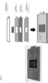
- the present invention provides microcapillary array flow cells and methods for lateral loading of solutions into these flow cells, as described herein and shown in the accompanying figures which find use in the high-throughput systems described herein.
- Such flow cells can comprise the microcapillary array as described under the section "Microcavity Array" provided above.
- a microcapillary array flow cell provides for distributing a fluid to a fluid access region encompassing a chip.
- the chip comprises a plurality of microcapillary wells.
- the fluid for distribution does not comprise a biomolecule for specific, targeted and/or particular binding to one or more components in the microcapillary well.
- a biomolecule includes but is not limited to an antibody, an antibody fragment, a whole cell, a cell fragment, a bacterium, a virus, a viral fragment, and/or a protein.
- the fluid for distribution does comprise a reagent.
- the fluid for distribution comprises a reagent such as a lysis buffer.
- the fluid for distribution comprises a reagent such as a wash buffer.
- the fluid for distribution comprises a sample, for example for loading the sample into the microcapillary wells of the microcapillary array flow cell.
- the microcapillary array flow cell comprises several different features.
- the microcapillary array flow cell comprises i) a height limiting support member comprising a fluid inlet hole, a fluid outlet hole, and an air vent hole in fluid communication, ii) an alignment member in fluid communication with i) and whose upper surface is lower than said chip comprising said plurality of microcapillary wells, iii) a sealing gasket in fluid communication with iii), wherein said sealing gasket encompasses said plurality of microcapillary wells, and iv) a base layer in fluid communication with iv) and which comprises the bottom planar surface, wherein said microcapillary wells are open to at least one planar surface, wherein said fluid is distributed in a lateral path perpendicular to said microcapillary wells, wherein the exit pressure of the fluid from the outlet hole at the bottom planar surface is lower than the surface tension of water or lower than the capillary pressure, and wherein said fluid is distributed into
- the microcapillary array flow cell comprises several different features.
- the microcapillary array flow cell comprises i) a height limiting support member comprising a fluid inlet hole, a fluid outlet hole, and an air vent hole in fluid communication, ii) an alignment member in fluid communication with i) and whose upper surface is lower than said chip comprising said plurality of microcapillary wells, iii) a sealing gasket in fluid communication with iii), wherein said sealing gasket encompasses said plurality of microcapillary wells, and iv) a base layer in fluid communication with iv) and which comprises the bottom planar surface, wherein said microcapillary wells are open to at least one planar surface, wherein said fluid is distributed in a lateral path perpendicular to said microcapillary wells, wherein the exit fluidic resistance is lower than the liquid surface tension in the microcapillary well, and wherein said fluid is distributed into said microcapillary wells.
- the lowest resistance is the outlet resistance and the fluid flows the correct path (e.g ., through the flow path and into the microcapillary wells, as provided in for example, in the figures, particularly Figures 1 , 4 , and 9-10 ) and does not flow out the microcapillary array flow cell base layer or bottom layer.
- the fluid inlet hole facilitates fluid distribution into said microcapillary wells.
- the fluid outlet hole facilitates fluid distribution into said microcapillary wells.
- the air vent hole facilitates fluid distribution into said microcapillary wells.
- the fluid inlet hole, the fluid outlet hole, and the air vent hole facilitate fluid distribution into said microcapillary wells.
- the microcapillary wells are open to two planar surfaces. In the present invention the microcapillary wells are through holes. In some embodiments, the microcapillary wells are through holes open to two planar surfaces.
- the fluid in the microcapillary array flow cell is held in the microcapillary wells by surface tension.
- the surface tension is the only force holding the fluid in the microcapillary wells.
- the height limiting support member is located about 0.05 mm to about 10 mm above said chip comprising said plurality of microcapillary wells.
- the height limiting support member is located about 0.05 mm to about 9 mm above said chip comprising said plurality of microcapillary wells. In some embodiments, the height limiting support member is located about 0.05 mm to about 8 mm above said chip comprising said plurality of microcapillary wells. In some embodiments, the height limiting support member is located about 0.05 mm to about 7 mm above said chip comprising said plurality of microcapillary wells. In some embodiments, the height limiting support member is located about 0.05 mm to about 6 mm above said chip comprising said plurality of microcapillary wells.
- the height limiting support member is located about 0.05 mm to about 5 mm above said chip comprising said plurality of microcapillary wells. In some embodiments, the height limiting support member is located about 0.05 mm to about 4 mm above said chip comprising said plurality of microcapillary wells. In some embodiments, the height limiting support member is located about 0.05 mm to about 3 mm above said chip comprising said plurality of microcapillary wells. In some embodiments, the height limiting support member is located about 0.05 mm to about 2 mm above said chip comprising said plurality of microcapillary wells.
- the height limiting support member is located about 0.05 mm to about 1 mm above said chip comprising said plurality of microcapillary wells. In some embodiments, the height limiting support member is located about 0.1 mm to about 10 mm above said chip comprising said plurality of microcapillary wells. In some embodiments, the height limiting support member is located about 0.1 mm to about 9 mm above said chip comprising said plurality of microcapillary wells. In some embodiments, the height limiting support member is located about 0.1 mm to about 8 mm above said chip comprising said plurality of microcapillary wells.
- the height limiting support member is located about 0.1 mm to about 7 mm above said chip comprising said plurality of microcapillary wells. In some embodiments, the height limiting support member is located about 0.1 mm to about 6 mm above said chip comprising said plurality of microcapillary wells. In some embodiments, the height limiting support member is located about 0.1 mm to about 5 mm above said chip comprising said plurality of microcapillary wells. In some embodiments, the height limiting support member is located about 0.1 mm to about 4 mm above said chip comprising said plurality of microcapillary wells.
- the height limiting support member is located about 0.1 mm to about 3 mm above said chip comprising said plurality of microcapillary wells. In some embodiments, the height limiting support member is located about 0.1 mm to about 2 mm above said chip comprising said plurality of microcapillary wells. In some embodiments, the height limiting support member is located about 0.1 mm to about 1 mm above said chip comprising said plurality of microcapillary wells. In some embodiments, the height limiting support member is located about 0.5 mm to about 10 mm above said chip comprising said plurality of microcapillary wells.
- the height limiting support member is located about 0.5 mm to about 9 mm above said chip comprising said plurality of microcapillary wells. In some embodiments, the height limiting support member is located about 0.5 mm to about 8 mm above said chip comprising said plurality of microcapillary wells. In some embodiments, the height limiting support member is located about 0.5 mm to about 7 mm above said chip comprising said plurality of microcapillary wells. In some embodiments, the height limiting support member is located about 0.5 mm to about 6 mm above said chip comprising said plurality of microcapillary wells.
- the height limiting support member is located about 0.5 mm to about 5 mm above said chip comprising said plurality of microcapillary wells. In some embodiments, the height limiting support member is located about 0.5 mm to about 4 mm above said chip comprising said plurality of microcapillary wells. In some embodiments, the height limiting support member is located about 0.5 mm to about 3 mm above said chip comprising said plurality of microcapillary wells. In some embodiments, the height limiting support member is located about 0.5 mm to about 2 mm above said chip comprising said plurality of microcapillary wells.
- the height limiting support member is located about 0.5 mm to about 1 mm above said chip comprising said plurality of microcapillary wells. In some embodiments, the height limiting support member is located about 1 mm to about 10 mm above said chip comprising said plurality of microcapillary wells. In some embodiments, the height limiting support member is located about 1 mm to about 9 mm above said chip comprising said plurality of microcapillary wells. In some embodiments, the height limiting support member is located about 1 mm to about 8 mm above said chip comprising said plurality of microcapillary wells. In some embodiments, the height limiting support member is located about 1 mm to about 7 mm above said chip comprising said plurality of microcapillary wells.
- the height limiting support member is located about 1 mm to about 6 mm above said chip comprising said plurality of microcapillary wells. In some embodiments, the height limiting support member is located about 1 mm to about 5 mm above said chip comprising said plurality of microcapillary wells. In some embodiments, the height limiting support member is located about 1 mm to about 4 mm above said chip comprising said plurality of microcapillary wells. In some embodiments, the height limiting support member is located about 1 mm to about 3 mm above said chip comprising said plurality of microcapillary wells. In some embodiments, the height limiting support member is located about 1 mm to about 2 mm above said chip comprising said plurality of microcapillary wells. In some embodiments, the height limiting support member is located about 1 mm to about 1 mm above said chip comprising said plurality of microcapillary wells.
- the flow cell may be for a "large" 52 mm x 52 mm array.
- the array in order to properly distribute the liquid, the array is divided into two flow paths.
- the flow cell comprises (from top to bottom) the following components: a 1/8" PMMA, a 5mil PET with 3M 9469 PSA laminated to both sides, a large format microcapillary glass chip, a 1 mm PMMA, and a 0.5 mm PMMA with 3M 9469 PSA laminated to the top of the PMMA.
- the flow cell may be for two "small" 25 mm x 25 mm arrays. In some embodiments, in order to properly distribute the liquid, the array is divided into two flow paths. In some embodiments, the flow cell comprises (from top to bottom) the following components: a 1/8" PMMA, a 5mil PET with 3M 9469 PSA laminated to both sides, a small format microcapillary glass chip, a 1 mm PMMA, and a and a 0.5 mm PMMA with 3M 9469 PSA laminated to the top of the PMMA.
- the fluid is pumped into the fluid inlet hole by an inlet pump. In some embodiments, the fluid is pumped out of the fluid outlet hole by an outlet pump. In some embodiments, the fluid is pumped into said fluid inlet hole by an inlet pump and the fluid is pumped out of the fluid outlet hole by an outlet pump. In some embodiments, the pumping rate of the outlet pump is equal to the pumping rate of the inlet pump. In some embodiments, the pumping rate of the outlet pump is faster than the pumping rate of the inlet pump. In some embodiments, the pumping rate of the outlet pump is one-fold, two-fold, three-fold, or four-fold faster than the pumping rate of the inlet pump.
- the pumping rate of the outlet pump is one-fold faster than the pumping rate of the inlet pump. In some embodiments, the pumping rate of the outlet pump is two-fold faster than the pumping rate of the inlet pump. In some embodiments, the pumping rate of the outlet pump is three-fold faster than the pumping rate of the inlet pump. In some embodiments, the pumping rate of the outlet pump is four-fold faster than the pumping rate of the inlet pump.
- a first fluid for distribution is pumped into said inlet hole, followed sequentially by pumping in a second fluid for distribution.
- 1 to 4 volumes of the second fluid for distribution is pumped into said inlet hole.
- 1 to 3 volumes of the second fluid for distribution is pumped into said inlet hole.
- 1 volume of the second fluid for distribution is pumped into said inlet hole.
- 2 volumes of the second fluid for distribution is pumped into said inlet hole.
- 3 volumes of the second fluid for distribution is pumped into said inlet hole.
- 4 volumes of the second fluid for distribution is pumped into said inlet hole.
- the second fluid is exchanged at least about 90%, at least about at least about 92%, at least about 95%, at least about 98%, at least about 99%, at least about 99.9% or at least about 100%.
- the first fluid for distribution is completely exchanged (e.g., completely replaced) with the second fluid for distribution.
- the fluid exchange over the surface e.g ., in the flow path
- the fluid exchange over the surface occurs in about 30 seconds, 1 minute, 90 seconds, or about 2 minutes.
- the fluid exchange over the surface ( e.g ., in the flow path) occurs in about 1 minute.
- the liquid within the microcapillary array well is exchanged by diffusion.
- the liquid within the microcapillary array well is exchanged by diffusion which occurs over about 15 minutes, about 20 minutes, about 25 minutes, about 30 minutes, or about 35 minutes.
- the second fluid for distribution is pumped into said inlet hole, a third fluid for distribution is pumped into said inlet hole.
- 1 to 4 volumes of the third fluid for distribution is pumped into said inlet hole.
- 1 to 3 volumes of the third fluid for distribution is pumped into said inlet hole.
- 1 volume of the third fluid for distribution is pumped into said inlet hole.
- 2 volumes of the third fluid for distribution is pumped into said inlet hole.
- 3 volumes of the third fluid for distribution is pumped into said inlet hole.
- 4 volumes of the third fluid for distribution is pumped into said inlet hole.
- the third fluid is exchanged at least about 90%, at least about at least about 92%, at least about 95%, at least about 98%, at least about 99%, at least about 99.9% or at least about 100%.
- the second fluid for distribution is completely exchanged ( e.g ., completely replaced) with the third fluid for distribution.
- the fluid exchange over the surface e.g ., in the flow path
- the fluid exchange over the surface occurs in about 30 seconds, 1 minute, 90 seconds, or about 2 minutes.
- the fluid exchange over the surface ( e.g ., in the flow path) occurs in about 1 minute.
- the liquid within the microcapillary array well is exchanged by diffusion.
- the liquid within the microcapillary array well is exchanged by diffusion which occurs over about 15 minutes, about 20 minutes, about 25 minutes, about 30 minutes, or about 35 minutes.
- the volume over the flow cell can range from about 100 uL to about 10 mL. In some embodiments, the volume over the flow cell can range from about 1 mL to about 10 mL. In some embodiments, the volume over the flow cell can range from about 1mL to about 9 mL. In some embodiments, the volume over the flow cell can range from about 1 mL to about 8 mL. In some embodiments, the volume over the flow cell can range from about 1mL to about 7 mL. In some embodiments, the volume over the flow cell can range from about 1 mL to about 6 mL. In some embodiments, the volume over the flow cell can range from about 1 mL to about 5 mL.
- the volume over the flow cell can range from about 1 mL to about 4 mL. In some embodiments, the volume over the flow cell can range from about 1 mL to about 3 mL. In some embodiments, the volume over the flow cell can range from about 1 mL to about 2 mL. In some embodiments, the volume over the flow cell can range from about 100 uL to about 1 mL. In some embodiments, the volume over the flow cell can range from about 100 uL to about 750 uL. In some embodiments, the volume over the flow cell can range from about 100 uL to about 500 uL. In some embodiments, the volume over the flow cell can range from about 100 uL to about 250 uL.
- the volume over the flow cell can range from about 250 uL to about 1 mL. In some embodiments, the volume over the flow cell can range from about 250 uL to about 750 uL. In some embodiments, the volume over the flow cell can range from about 250 uL to about 500 uL.
- the inlet pump flow rates can be up to about 1 mL/min to about 5 mL/min. In some embodiments, the inlet pump flow rates can be up to about 5 mL/min. In some embodiments, the inlet pump flow rates can be up to about 4 mL/min. In some embodiments, the inlet pump flow rates can be up to about 3 mL/min. In some embodiments, the inlet pump flow rates can be up to about 2 mL/min. In some embodiments, the inlet pump flow rates can be up to about 1 mL/min.
- a syringe pump can be employed as the inlet pump.
- the inlet pump is a syringe pump.
- the inlet pump is a TriContinent Syringe pump.
- a peristaltic pump can be employed as the outlet pump.
- the outlet pump is a peristaltic pump.
- the outlet pump is a Welco peristaltic pump.
- the fluid distribution occurs at a flow rate of about 1 ⁇ L/min to about 10 mL/second. In some embodiments, the fluid distribution occurs at a flow rate of about 1 mL/min to about 1 mL/second. In some embodiments, the fluid distribution occurs at a flow rate of about 0.5 mL/min to about 1 mL/second. In some embodiments, the fluid distribution occurs at a flow rate of about 1 mL/min to about 0.5 mL/second. In some embodiments, the fluid distribution occurs at a flow rate of about 0.5 mL/min to about 0.5 mL/second. In some embodiments, the fluid distribution occurs at a flow rate of about 0.25 mL/min to about 0.5 mL/second.
- the fluid distribution occurs at a flow rate of about 0.5 mL/min to about 0.25 mL/second. In some embodiments, the fluid distribution occurs at a flow rate of about 1 mL/min to about 0.25 mL/second. In some embodiments, the fluid distribution occurs at a flow rate of about 0.25 mL/min to about 1 mL/second. In some embodiments, the fluid distribution occurs at a flow rate of about 1 mL/min. In some embodiments, the fluid distribution occurs at a flow rate of about 0.9 mL/min. In some embodiments, the fluid distribution occurs at a flow rate of about 0.8 mL/min. In some embodiments, the fluid distribution occurs at a flow rate of about 0.7 mL/min.
- the fluid distribution occurs at a flow rate of about 0.6 mL/min. In some embodiments, the fluid distribution occurs at a flow rate of about 0.5 mL/min. In some embodiments, the fluid distribution occurs at a flow rate of about 0.4 mL/min. In some embodiments, the fluid distribution occurs at a flow rate of about 0.3 mL/min. In some embodiments, the fluid distribution occurs at a flow rate of about 0.2 mL/min. In some embodiments, the fluid distribution occurs at a flow rate of about 0.1 mL/min. In some embodiments, the fluid distribution occurs at a flow rate of about 1 mL/60 seconds to about 1 mL/second.
- the fluid distribution occurs at a flow rate of about 1 mL/55 seconds to about 1 mL/second. In some embodiments, the fluid distribution occurs at a flow rate of about 1 mL/50 seconds to about 1 mL/second. In some embodiments, the fluid distribution occurs at a flow rate of about 1 mL/45 seconds to about 1 mL/second. In some embodiments, the fluid distribution occurs at a flow rate of about 1 mL/40 seconds to about 1 mL/second. In some embodiments, the fluid distribution occurs at a flow rate of about 1 mL/35 seconds to about 1 mL/second. In some embodiments, the fluid distribution occurs at a flow rate of about 1 mL/30 seconds to about 1 mL/second.
- the fluid distribution occurs at a flow rate of about 1 mL/25 seconds to about 1 mL/second. In some embodiments, the fluid distribution occurs at a flow rate of about 1 mL/20 seconds to about 1 mL/second. In some embodiments, the fluid distribution occurs at a flow rate of about 1 mL/15 seconds to about 1 mL/second. In some embodiments, the fluid distribution occurs at a flow rate of about 1 mL/10 seconds to about 1 mL/second. In some embodiments, the fluid distribution occurs at a flow rate of about 1 mL/5 seconds to about 1 mL/second.
- the fluid distribution occurs at a flow rate of about 1 ⁇ L/min to about 9 mL/second. In some embodiments, the fluid distribution occurs at a flow rate of about 1 ⁇ L/min to about 8 mL/second. In some embodiments, the fluid distribution occurs at a flow rate of about 1 ⁇ L/min to about 7 mL/second. In some embodiments, the fluid distribution occurs at a flow rate of about 1 ⁇ L/min to about 6 mL/second. In some embodiments, the fluid distribution occurs at a flow rate of about 1 ⁇ L/min to about 5 mL/second. In some embodiments, the fluid distribution occurs at a flow rate of about 1 ⁇ L/min to about 4 mL/second.
- the fluid distribution occurs at a flow rate of about 1 ⁇ L/min to about 3 mL/second. In some embodiments, the fluid distribution occurs at a flow rate of about 1 ⁇ L/min to about 2 mL/second. In some embodiments, the fluid distribution occurs at a flow rate of about 1 ⁇ L/min to about 1 mL/second. In some embodiments, the fluid distribution occurs at a flow rate of about 1 ⁇ L/min to about 10 mL/second. In some embodiments, the fluid distribution occurs at a flow rate of about 1 ⁇ L/min to about 10 mL/second.
- the fluid distribution occurs at a maximum pressure of less than 34.4738 kPa (5 PSI). In some embodiments, the fluid distribution occurs at a maximum pressure of less than 27.579 kPa (4 PSI). In some embodiments, the fluid distribution occurs at a maximum pressure of less than 20.6843 kPa (3 PSI). In some embodiments, the fluid distribution occurs at a maximum pressure of less than 13.7895 kPa (2 PSI). In some embodiments, the fluid distribution occurs at a maximum pressure of less than 6.89476 kPa (1 PSI). In some embodiments, when the fluid distribution occurs at a pressure of equal to or more than 34.4738 kPa (5 PSI), this results in fluid leakage. In some embodiments, fluid distribution occurs at a pressure equal to or above 34.4738 kPa (5 PSI) results in fluid leakage.
- the fluid distribution occurs at sufficiently low pressure to avoid fluid leakage.
- a sufficiently low pressure to avoid fluid leakage is a pressure lower of about 6.89476 kPa (1 PSI) to about 68.9476 kPa (10 PSI).
- a sufficiently low pressure to avoid fluid leakage is a pressure lower of about 13.7895 kPa (2 PSI) to about 68.9476 kPa (10 PSI).
- a sufficiently low pressure to avoid fluid leakage is a pressure lower of about 13.7895 kPa (2 PSI) to about 55.1581 kPa (8 PSI).
- a sufficiently low pressure to avoid fluid leakage is a pressure lower of about 13.7895 kPa (2 PSI) to about 41.3685 kPa (6 PSI). In some embodiments, a sufficiently low pressure to avoid fluid leakage is a pressure lower of about 27.579 kPa (4 PSI) to about 55.1581 kPa (8 PSI). In some embodiments, a sufficiently low pressure to avoid fluid leakage is a pressure lower of about 13.7895 kPa (2 PSI) to about 27.579 kPa (4 PSI). In some embodiments, a sufficiently low pressure to avoid fluid leakage is a pressure lower than about 68.9476 kPa (10 PSI).
- a sufficiently low pressure to avoid fluid leakage is a pressure lower than about 62.0528 kPa (9 PSI). In some embodiments, a sufficiently low pressure to avoid fluid leakage is a pressure lower than about 55.1581 kPa (8 PSI). In some embodiments, a sufficiently low pressure to avoid fluid leakage is a pressure lower than about 48.2633 kPa (7 PSI). In some embodiments, a sufficiently low pressure to avoid fluid leakage is a pressure lower than about 41.3685 kPa (6 PSI). In some embodiments, a sufficiently low pressure to avoid fluid leakage is a pressure lower than about 34.4738 kPa (5 PSI).
- a sufficiently low pressure to avoid fluid leakage is a pressure lower than about 27.579 kPa (4 PSI). In some embodiments, a sufficiently low pressure to avoid fluid leakage is a pressure lower than about 20.6843 kPa (3 PSI). In some embodiments, a sufficiently low pressure to avoid fluid leakage is a pressure lower than about 20.6843 kPa (3 PSI). In some embodiments, a sufficiently low pressure to avoid fluid leakage is a pressure lower than about 6.89476 kPa (1 PSI). In some embodiments fluid leakage is considered to occur anytime the fluid for distribution exits the microcapillary flow cell array through any means other than being pumped out through an outlet hole.
- fluid leakage is indicative of an erroneous pressure differential. In some embodiments, fluid leakage is indicative of an erroneous flow rate. In some embodiments, when the pressure in the microcapillary flow cell array is too high, or above a threshold pressure, fluid leakage occurs. In some embodiments, when the flow rate of the fluid for distribution in the microcapillary flow cell array is too fast, or above a threshold rate, fluid leakage occurs.
- the exit pressure is less than 0.5 kPa. In some embodiments, the exit pressure is less than 0.4 kPa. In some embodiments, the exit pressure is less than 0.3 kPa. In some embodiments, the exit pressure is less than 0.2 kPa. In some embodiments, the exit pressure is less than 0.1 kPa. In some embodiments, the back pressure is less than 0.5 kPa. In some embodiments, the back pressure is less than 0.4 kPa. In some embodiments, the back pressure is less than 0.3 kPa. In some embodiments, the back pressure is less than 0.2 kPa. In some embodiments, the back pressure is less than 0.1 kPa. In some embodiments, an exit pressure above 0.5 kPa results in fluid leakage.
- the maximum pressure within said microcapillary wells before leaking is calculated by the following formula: F capillary ⁇ F inlet + F outlet + F gravity , sample .
- F inlet is in the inlet pump pressure. With the 2 nd pump, F outlet should be -0.
- F gravity ⁇ g ⁇ r 2 ⁇ h
- the fluid for distribution comprises a sample loading buffer. In some embodiments, the fluid for distribution is an aqueous based fluid. In some embodiments, the fluid for distribution comprises an oil phase. In some embodiments, the oil phase is a mineral oil or similar oil.
- the fluid for distribution comprises a sample. In some embodiments, the fluid for distribution comprises a sample, for example for loading the sample into the microcapillary wells of the microcapillary array flow cell.
- the fluid for distribution comprises a wash buffer.
- the wash buffer is 1x phosphate buffered saline, or HEPES (4-(2-hydroxyethyl)-1-piperazineethanesulfonic acid) Buffer, or Live Cell Imaging Solution (Invitrogen).
- the fluid for distribution comprises a growth media.
- the growth media is comprises a growth media selected from the group consisting of DMEM, RPMI, and IMEM.
- the fluid for distribution comprises a growth media.
- the growth media comprises a growth media selected from the group consisting of DMEM, RPMI, and IMEM.
- the growth media comprises DMEM.
- the fluid for distribution comprises a reagent.
- the reagent is a lysis buffer.
- lysis buffer lyse cells.
- Two recipes for lysis buffer are 1) 1% v/v NP-40, 20mM Tris-HCL, 5mM Sodium Pyrophosphate, 5mM EDTA; 2) 1% Triton, 20 mM Tris-HCl, 150 mM NaCl, 5mM Sodium Pyrophosphate, 5mM EDTA.
- Detergent/surfactant Triton/NP-40
- the reagent is one or more antibodies.
- antibodies include primary antibodies: anti-CD25, anti-CD69 antibodies, anti-CD107a antibodies.
- Other antibodies include secondary antibodies against Mouse, Human, Rabbit, Rat, Goat, Chicken, Sheep, Guinea pig, Hamster, Bovine, Donkey, Dog, Camelid, Cat, Pig, Non-human primate, and Horse.
- the reagent is a fluorescently labeled antibody.
- the microcapillary array flow cell is mounted onto a microscope stage, such as one as described above under the "High-throughput imaging systems section".
- the said microscope stage mounting allows for imaging of said microcapillary array contents. In some embodiments, the said microscope stage mounting allows for collection and/or recover of the microcapillary array contents.
- the microscope stage mounting allows for recovery of said microcapillary array contents with a laser.
- the recovered contents comprise cells.
- the recovered contents comprise live cells.
- the recovered contents comprise dead cells.
- the recovered cells can be further analyzed for the presence of one or more nucleic acids.
- the recovered cells can be further analyzed for the presence of one or more amino acids.
- the internal diameter of the microcapillary wells is from about 1 ⁇ m to about 500 ⁇ m. In various embodiments, the internal diameter of each microcapillary in the array ranges from between approximately 1 ⁇ m and 500 ⁇ m. In some arrays, each microcapillary can have an internal diameter in the range between approximately 1 ⁇ m and 300 ⁇ m; optionally between approximately 1 ⁇ m and 100 ⁇ m; further optionally between approximately 1 ⁇ m and 75 ⁇ m; still further optionally between approximately 1 ⁇ m and 50 ⁇ m; and still further optionally between approximately 5 ⁇ m and 50 ⁇ m.
- the open area of the array comprises up to 90% of the open area (OA), so that, when the pore diameter varies between 1 ⁇ m and 500 ⁇ m, the number of microcapillaries per cm of the array varies between approximately 460 and over 11 million. In some embodiments, the number of microcapillary wells per cm of said chip comprising said microcapillary wells is about 460 to about 11 million or more. In some microcapillary arrays, the open area of the array comprises about 67% of the open area, so that, when the pore size varies between 1 ⁇ m and 500 ⁇ m, the number of microcapillaries per square cm of the array varies between approximately 340 and over 800,000.
- the number of microcapillaries per square cm of the array is approximately 400; 800; 1000; 2000; 4000; 5000; 10,0000; 25,000; 50,000; 75,000; 100,000; 200,000; 300,000; 400,000; 500,000; 600,000; 700,000; 800,000; 900,000; 1,000,000 or more.
- the present invention also provides a method for loading a fluid into a microcapillary well.
- the method for loading a fluid into a microcapillary well comprises pumping the fluid for distribution into said fluid inlet hole of the microcapillary array flow cell as described above.
- the method allows for uniform distribution of the fluid for distribution.
- the method allows for exchange of a first fluid for distribution with a second fluid for distribution.
- the first fluid for distribution is a sample buffer and the second fluid for distribution is a wash buffer.
- the first fluid for distribution is a wash buffer and the second fluid for distribution is a wash buffer.
- the method allows for exchange of a second fluid for distribution with a third fluid for distribution.
- the second fluid for distribution is a wash buffer and the third fluid for distribution is a wash buffer.
- the invention provides a method for distribution of a fluid in a microcapillary array flow cell, wherein said fluid for distribution is pumped into the microcapillary array flow cell at a pressure lower than the pressure for which the fluid is exiting the microcapillary array flow cell, such that fluid does not leak out of the microcapillary array flow cell.
- the invention provides a method for distribution of a fluid in a microcapillary array flow cell, wherein said fluid for distribution is pumped into the microcapillary array flow cell at a pressure lower than the pressure for which the fluid is exiting the microcapillary array flow cell, wherein said fluid distribution occurs at a maximum pressure of less than 34.4738 kPa (5 PSI), such that fluid does not leak out of the microcapillary array flow cell.
- the invention provides a method for distribution of a fluid in a microcapillary array flow cell, wherein said fluid for distribution is pumped into the microcapillary array flow cell at a pressure lower than the pressure for which the fluid is exiting the microcapillary array flow cell, wherein said exit pressure is less than 0.5 kPa, such that fluid does not leak out of the microcapillary array flow cell.
- the invention provides a method for distribution of a fluid in a microcapillary array flow cell, wherein said fluid for distribution is pumped into the microcapillary array flow cell at a pressure lower than the pressure for which the fluid is exiting the microcapillary array flow cell, wherein the maximum pressure within said microcapillary wells before leaking is calculated by the following formula: F capillary ⁇ F inlet + F outlet + F gravity , sample , such that fluid does not leak out of the microcapillary array flow cell.
- the invention provides a method for distribution of a fluid in a microcapillary array flow cell, wherein said fluid for distribution is pumped into the microcapillary array flow cell and out of the microcapillary array flow cell and wherein the exit pressure of the fluid from an outlet hole is lower than the surface tension of water or lower than the capillary pressure, wherein the fluid is distributed into the microcapillary wells, and wherein the fluid does not leak out of the microcapillary array flow cell.
- the invention provides a method for distribution of a fluid in a microcapillary array flow cell, wherein said fluid for distribution is pumped into the microcapillary array flow cell and out of the microcapillary array flow cell and wherein the exit pressure of the fluid from an outlet hole is lower than the surface tension of water or lower than the capillary pressure, wherein said fluid distribution occurs at a maximum pressure of less than 34.4738 kPa (5 PSI), wherein the fluid is distributed into the microcapillary wells, and wherein the fluid does not leak out of the microcapillary array flow cell.
- a fluid for distribution is pumped into the microcapillary array flow cell and out of the microcapillary array flow cell and wherein the exit pressure of the fluid from an outlet hole is lower than the surface tension of water or lower than the capillary pressure, wherein said fluid distribution occurs at a maximum pressure of less than 34.4738 kPa (5 PSI), wherein the fluid is distributed into the microcapillary wells, and wherein the fluid does not leak out of the
- the invention provides a method for distribution of a fluid in a microcapillary array flow cell, wherein said fluid for distribution is pumped into the microcapillary array flow cell and out of the microcapillary array flow cell and wherein the exit pressure of the fluid from an outlet hole is lower than the surface tension of water or lower than the capillary pressure, wherein said fluid distribution occurs at sufficiently low pressure to avoid fluid leakage, wherein the fluid is distributed into the microcapillary wells, and wherein the fluid does not leak out of the microcapillary array flow cell.
- the invention provides a method for distribution of a fluid in a microcapillary array flow cell, wherein said fluid for distribution is pumped into the microcapillary array flow cell and out of the microcapillary array flow cell and wherein the exit pressure of the fluid from an outlet hole is lower than the surface tension of water or lower than the capillary pressure, wherein said exit pressure is less than 0.5 kPa, wherein the fluid is distributed into the microcapillary wells, and wherein the fluid does not leak out of the microcapillary array flow cell.
- the invention provides a method for distribution of a fluid in a microcapillary array flow cell, wherein said fluid for distribution is pumped into the microcapillary array flow cell and out of the microcapillary array flow cell and wherein the exit pressure of the fluid from an outlet hole is lower than the surface tension of water or lower than the capillary pressure, wherein the maximum pressure within said microcapillary wells before leaking is calculated by the following formula: F capillary ⁇ F inlet + F outlet + F gravity , sample , wherein the fluid is distributed into the microcapillary wells, and wherein the fluid does not leak out of the microcapillary array flow cell.
- the invention provides a method for distribution of a fluid in a microcapillary array flow cell, wherein said fluid for distribution is pumped into the microcapillary array flow cell and out of the microcapillary array flow cell, wherein the fluid distribution occurs at a flow rate of about 1 ⁇ L/min to about 10 mL/second, wherein the fluid is distributed into the microcapillary wells, and wherein the fluid does not leak out of the microcapillary array flow cell.
- the invention provides a method for distribution of a fluid in a microcapillary array flow cell, wherein said fluid for distribution is pumped into the microcapillary array flow cell and out of the microcapillary array flow cell, wherein the fluid distribution occurs at a flow rate of about 1 ⁇ L/min to about 10 mL/second, wherein the fluid is distributed into the microcapillary wells, and wherein the fluid does not leak out of the microcapillary array flow cell.
- the invention provides a method for distribution of a fluid in a microcapillary array flow cell, wherein said fluid for distribution is pumped into the microcapillary array flow cell and out of the microcapillary array flow cell, wherein the fluid distribution occurs at a flow rate of about 1 ⁇ L/min to about 10 mL/second, wherein said fluid distribution occurs at a maximum pressure of less than 34.4738 kPa (5 PSI), wherein said fluid distribution occurs at sufficiently low pressure to avoid fluid leakage, wherein the fluid is distributed into the microcapillary wells, and wherein the fluid does not leak out of the microcapillary array flow cell.
- the invention provides a method for distribution of a fluid in a microcapillary array flow cell, wherein said fluid for distribution is pumped into the microcapillary array flow cell and out of the microcapillary array flow cell, wherein the fluid distribution occurs at a flow rate of about 1 ⁇ L/min to about 10 mL/second, wherein said exit pressure is less than 0.5 kPa, wherein the fluid is distributed into the microcapillary wells, and wherein the fluid does not leak out of the microcapillary array flow cell.
- the invention provides a method for distribution of a fluid in a microcapillary array flow cell, wherein said fluid for distribution is pumped into the microcapillary array flow cell and out of the microcapillary array flow cell, wherein the fluid distribution occurs at a flow rate of about 1 ⁇ L/min to about 10 mL/second, wherein the maximum pressure within said microcapillary wells before leaking is calculated by the following formula: F capillary ⁇ F inlet + F outlet + F gravity , sample , wherein the fluid is distributed into the microcapillary wells, and wherein the fluid does not leak out of the microcapillary array flow cell.
- the invention provides a method for distribution of a fluid in a microcapillary array flow cell, wherein said fluid for distribution is pumped into the microcapillary array flow cell and out of the microcapillary array flow cell, wherein said fluid distribution occurs at a maximum pressure of less than 34.4738 kPa (5 PSI), wherein the fluid is distributed into the microcapillary wells, and wherein the fluid does not leak out of the microcapillary array flow cell.
- a fluid for distribution is pumped into the microcapillary array flow cell and out of the microcapillary array flow cell, wherein said fluid distribution occurs at a maximum pressure of less than 34.4738 kPa (5 PSI), wherein the fluid is distributed into the microcapillary wells, and wherein the fluid does not leak out of the microcapillary array flow cell.
- the invention provides a method for distribution of a fluid in a microcapillary array flow cell, wherein said fluid for distribution is pumped into the microcapillary array flow cell and out of the microcapillary array flow cell, wherein said fluid distribution occurs at sufficiently low pressure to avoid fluid leakage, wherein the fluid is distributed into the microcapillary wells, and wherein the fluid does not leak out of the microcapillary array flow cell.
- the invention provides a method for distribution of a fluid in a microcapillary array flow cell, wherein said fluid for distribution is pumped into the microcapillary array flow cell and out of the microcapillary array flow cell, wherein said exit pressure is less than 0.5 kPa, wherein the fluid is distributed into the microcapillary wells, and wherein the fluid does not leak out of the microcapillary array flow cell.
- the exit pressure is the fluidic resistance out of the lateral flow cell outlet.
- the invention provides a method for distribution of a fluid in a microcapillary array flow cell, wherein said fluid for distribution is pumped into the microcapillary array flow cell and out of the microcapillary array flow cell, wherein the maximum pressure within said microcapillary wells before leaking is calculated by the following formula: F capillary ⁇ F inlet + F outlet + F gravity , sample .
- F inlet is in the inlet pump pressure. With the 2 nd pump, F outlet should be -0.
- F gravity ⁇ g ⁇ r 2 ⁇ h
- ⁇ density
- r capillary diameter
- the invention provides a method for distribution of a fluid in a microcapillary array flow cell, wherein said fluid for distribution is pumped into the microcapillary array flow cell and out of the microcapillary array flow cell, wherein the maximum pressure within said microcapillary wells before leaking is calculated by the following formula: F capillary ⁇ F inlet + F outlet + F gravity sample , wherein the fluid is distributed into the microcapillary wells, and wherein the fluid does not leak out of the microcapillary array flow cell.
- the invention provides a method for distribution of a fluid in a microcapillary array flow cell, wherein said fluid for distribution is pumped into the microcapillary array flow cell and out of the microcapillary array flow cell, wherein said fluid distribution occurs at a maximum pressure of less than 34.4738 kPa (5 PSI), wherein said fluid distribution occurs at sufficiently low pressure to avoid fluid leakage, wherein the fluid is distributed into the microcapillary wells, and wherein the fluid does not leak out of the microcapillary array flow cell.
- a maximum pressure of less than 34.4738 kPa 5 PSI
- the invention provides a method for distribution of a fluid in a microcapillary array flow cell, wherein said fluid for distribution is pumped into the microcapillary array flow cell and out of the microcapillary array flow cell, wherein said fluid distribution occurs at sufficiently low pressure to avoid fluid leakage, wherein said exit pressure is less than 0.5 kPa, wherein the fluid is distributed into the microcapillary wells, and wherein the fluid does not leak out of the microcapillary array flow cell.
- the invention provides a method for distribution of a fluid in a microcapillary array flow cell, wherein said fluid for distribution is pumped into the microcapillary array flow cell and out of the microcapillary array flow cell, wherein said fluid distribution occurs at a maximum pressure of less than 34.4738 kPa (5 PSI), wherein said exit pressure is less than 0.5 kPa, wherein the fluid is distributed into the microcapillary wells, and wherein the fluid does not leak out of the microcapillary array flow cell.
- the invention provides a method for distribution of a fluid in a microcapillary array flow cell, wherein said fluid for distribution is pumped into the microcapillary array flow cell and out of the microcapillary array flow cell, wherein the maximum pressure within said microcapillary wells before leaking is calculated by the following formula: F capillary ⁇ F inlet + F outlet + F gravity sample , wherein said exit pressure is less than 0.5 kPa, wherein the fluid is distributed into the microcapillary wells, and wherein the fluid does not leak out of the microcapillary array flow cell.
- the invention provides a method for distribution of a fluid in a microcapillary array flow cell, wherein said fluid for distribution is pumped into the microcapillary array flow cell and out of the microcapillary array flow cell, wherein said fluid distribution occurs at a maximum pressure of less than 34.4738 kPa (5 PSI), wherein the maximum pressure within said microcapillary wells before leaking is calculated by the following formula: F capillary ⁇ F inlet + F outlet + F gravity sample , wherein the fluid is distributed into the microcapillary wells, and wherein the fluid does not leak out of the microcapillary array flow cell.
- the invention provides a method for distribution of a fluid in a microcapillary array flow cell, wherein said fluid for distribution is pumped into the microcapillary array flow cell and out of the microcapillary array flow cell, wherein said fluid distribution occurs at sufficiently low pressure to avoid fluid leakage, wherein the maximum pressure within said microcapillary wells before leaking is calculated by the following formula: F capillary ⁇ F inlet + F outlet + F gravity sample , wherein the fluid is distributed into the microcapillary wells, and wherein the fluid does not leak out of the microcapillary array flow cell.
- the invention provides a method for distribution of a fluid in a microcapillary array flow cell, wherein said fluid for distribution is pumped into the microcapillary array flow cell and out of the microcapillary array flow cell, wherein the maximum pressure within said microcapillary wells before leaking is calculated by the following formula: F capillary ⁇ F inlet + F outlet + F gravity sample , wherein said exit pressure is less than 0.5 kPa, wherein the fluid is distributed into the microcapillary wells, and wherein the fluid does not leak out of the microcapillary array flow cell.
- Libraries that can be screened according to the present methods include any library comprising a plurality of molecules as well as mixtures and/or combinations thereof.
- libraries comprise samples comprising biological material.
- the library comprises samples comprising a plurality of one or more molecules and/or cells as well as mixtures and/or combinations thereof.
- the library comprises samples comprising a plurality of one or more proteins, polypeptides, nucleic acids, small molecules, dyes, and/or cells as well as mixtures and/or combinations thereof.
- molecules include any molecule.
- molecules include but are not limited to proteins, polypeptides, nucleic acids, small molecules, and/or dyes as well as mixtures and/or combinations thereof.
- libraries comprise samples comprising biological materials that comprise polypeptides, nucleic acids, small molecules, and/or cells as well as mixtures and/or combinations thereof.
- libraries comprise samples.
- samples include but are not limited to biological materials that comprise polypeptides, nucleic acids, small molecules, dyes, and/or cells as well as mixtures and/or combinations thereof.
- samples contain a least one molecules and/or cell to be screened.
- samples contain a least one to ten molecules and/or cells to be screened as well as mixtures and/or combinations thereof.
- samples contain a plurality of molecules and/or cells to be screened as well as mixtures and/or combinations thereof.
- the molecule to be screened is termed a target molecule.
- the cell to be screened is termed a target cell.
- the arrays provided herein allow for screening of libraries made up of proteins, polypeptides, nucleic acid, small molecules, dyes, and/or cells as well as mixtures and/or combinations thereof.
- the target molecule to be screened is a protein, polypeptide, nucleic acid, small molecule, dye, carbohydrate, lipid, or a combination of two or more of these target molecules.
- the proteins and/or polypeptides are selected from the group consisting of enzymes, ligands, and receptors.
- the target molecule can be a lipid-modified or glycosylated protein.
- the target molecule is a native protein.
- each capillary in the microcavity array used in the instant screening methods will contain different sample components.
- sample components can include, but are not limited to proteins, polypeptides, nucleic acids, small molecules, dyes, and/or cells ( i.e., target molecules and/or target cells) as well as mixtures and/or combinations thereof.
- the library for screening comprises the variant protein, variant polypeptide, variant nucleic acid, variant small molecule, variant dye, and/or variant cells exhibiting distinguishing characteristics.
- the variant protein, variant polypeptide, variant nucleic acid, variant small molecule, variant dye, and/or variant cells exhibit distinguishing characteristics, such that each microcavity comprises a sample that comprises a different target molecule and/or target cell from the sample found in each of the other microcavities within the array.
- one or more microcavities within the array comprise a sample that comprises the same target molecule and/or target cell as a sample found in at least one other microcavity within the array ( e . g ., as duplicates for comparison).
- the proteins and/or polypeptides in the library to be screened in the microcavity array can be variant proteins and/or polypeptides.
- Variant proteins include proteins and polypeptides which are distinguishable from one another based on at least one characteristic or feature.
- the variant proteins and/or polypeptides exhibit different amino acid sequences, exhibit different amino acid sequence lengths, are produced/generated by different methods, exhibit different activities, exhibit different chemical modifications, and/or exhibit different post-translational modifications.
- the variant proteins and/or polypeptides exhibit different amino acid sequences.
- the variant proteins and/or polypeptides exhibit different amino acid sequence lengths.
- the variant proteins and/or polypeptides are produced/generated by different methods. In some embodiments, the variant proteins and/or polypeptides exhibit different activities. In some embodiments, the variant proteins and/or polypeptides exhibit different chemical modifications. In some embodiments, the variant proteins and/or polypeptides exhibit different post-translational modifications. In some embodiments, the variant protein is one of a population of variant proteins and/or polypeptides that is being subjected to the screening method and analyzed using the microcavity arrays disclosed herein. The population of variant proteins and/or polypeptides can be any population of proteins that can be suitably distributed within a microcapillary array.
- the nucleic acids in the library to be screened in the microcavity array can be variant nucleic acids.
- Variant nucleic acids include nucleic acids which are distinguishable from one another based on at least one characteristic or feature.
- the variant nucleic acids have different nucleotide sequences, have different nucleotide sequence lengths, have been produced/generated by different methods, have different methylation patterns, have different chemical modifications, and/or exhibit other distinguishing modifications.
- the variant nucleic acids have different nucleotide sequences.
- the variant nucleic acids have different nucleotide sequence lengths.
- the variant nucleic acids have been produced/generated by different methods.
- the variant nucleic acids have different methylation patterns. In some embodiments, the variant nucleic acids have different chemical modifications. In some embodiments, the variant nucleic acids exhibit other distinguishing modifications. In some embodiments, the nucleic acid is one of a population of variant nucleic acids that is being subjected to the screening method and analyzed using the microcavity arrays disclosed herein. The population of variant nucleic acids can be any population of nucleic acids that can be suitably distributed within a microcapillary array.
- the small molecules in the library to be screened in the microcavity array can be variant and/or different small molecules.
- Variant small molecules include small molecules which are distinguishable from one another based on at least one characteristic or feature.
- the variant small molecules have different structures, have been produced/generated by different methods, have different chemical modifications, and/or exhibit other distinguishing different features.
- the variant small molecules have different structures.
- the variant small molecules have been produced/generated by different methods.
- the variant small molecules have different chemical modifications.
- the variant small molecules exhibit other distinguishing different features.
- the small molecules are derivatives of one another.
- the small molecule is one of a population of small molecules that is being subjected to the screening method and analyzed using the microcavity arrays disclosed herein.
- the population of small molecules can be any population of small molecules that can be suitably distributed within a microcapillary array.
- the cells in the library to be screened in the microcavity array can be variant cells and/or cells of varying types.
- Variant cells include cells which are distinguishable from one another based on at least one characteristic or feature.
- the cells are derived from different samples, are derived from different patients, are derived from different diseases, have different chemical modifications, and/or have been genetically modified.
- Cells can include eukaryotic and prokaryotic cells.
- the cells are derived from different samples. In some embodiments, the cells are derived from different patients. In some embodiments, the cells are derived from different diseases. In some embodiments, the cells have different chemical modifications. In some embodiments, the cells have been genetically modified. In some embodiments, the cells can include human cells, mammalian cells, bacterial cells, and fungal cells, including yeast cells. In some embodiments, the cells can include human cells. In some embodiments, the cells can include mammalian cells. In some embodiments, the cells can include bacterial cells. In some embodiments, the cells can include fungal cells.
- the cells can include yeast cells
- the cell is one of a population of cells that is being subjected to the screening method and analyzed using the microcavity arrays disclosed herein.
- the population of cells can be any population of cells that can be suitably distributed within a microcapillary array.
- the population of proteins, polypeptides, nucleic acid, and/or cells is distributed in the microcavity array so that each microcavity comprises a small number of different variant proteins, variant polypeptides, variant nucleic acid, and/or cells.
- each microcavity comprises a single different variant protein, variant polypeptide, variant nucleic acid, and/or cell per microcavity.
- each microcavity comprises a single different variant protein per microcavity.
- each microcavity comprises a single different variant polypeptide per microcavity.
- each microcavity comprises a single different variant nucleic acid per microcavity.
- each microcavity comprises a single different cell per microcavity.
- the population of variant proteins, variant polypeptides, variant nucleic acid, and/or cells is chosen in combination with the other components within the composition.
- each microcavity in the microcavity array comprises 0 to 5 different variant proteins, variant polypeptides, variant nucleic acid, and/or cells from the population of variant proteins. In some embodiments, each microcavity in the microcavity array comprises 0 to 4, 0 to 3, 0 to 2, or even 0 to 1 different variant proteins from the population of variant proteins, variant polypeptides, variant nucleic acid, and/or cells.
- the variant proteins are soluble proteins, for example soluble proteins that are secreted by a cellular expression system.
- soluble variant proteins include antibodies and antibody fragments, alternative protein scaffolds, such as disulfide-bonded peptide scaffolds, extracellular domains of cell-surface receptor proteins, receptor ligands, such as, for example, G-protein coupled receptor ligands, other peptide hormones, lectins, and the like.
- the variant proteins screened using the instant methods do not need to be covalently attached to the cell or virus that expresses them in order to be identified following a screening assay.
- variant proteins identified in the instant screening methods need not be altered in any way either before or after their identification.
- the observed activities of the variant proteins in the screens are thus more likely to represent the actual activities of those proteins in their subsequent applications. Not needing to alter variant proteins or polypeptides prior to screening also allows for more efficient screening, saving costs and time for library preparation.
- the variant proteins to be screened are membrane-associated proteins, for example proteins typically associated with the surface of a cell or a viral particle in an expression system. Screening of cell-associated variant proteins may be desirable where the variant protein and its target molecule mediate interactions between two cells within a biological tissue. The ability to screen cell-associated variant proteins may also be desirable in screening for interactions with traditionally "non-druggable" protein targets, such as, for example, G-protein coupled receptors or ion channels. Again, not needing to alter variant proteins or polypeptides prior to screening also allows for more efficient screening, saving costs and time for library preparation.
- the variant nucleic acids to be screened include any nucleic acid or polynucleotide, including nucleic acids or polynucleotides that bind to or interact with proteins. Again, not needing to alter the nucleic acids or polynucleotides prior to screening also allows for more efficient screening, saving costs and time for library preparation.
- the protein to be screened is an antibody, antibody fragment, such as an Fc, or an antibody fusion, including for example Fc fusions.
- the antibody or antibody fragment can be labeled.
- the method employs the use of an antibody to bind to the target molecule to be screened.
- the antibody is a labeled primary antibody or a labeled secondary antibody as is used to bind to the target molecules.
- a primary antibody is typically considered to be an antibody that binds directly to an antigen of interest, whereas a secondary antibody is typically considered to be an antibody that binds to a constant region on a primary antibody for purposes of labeling the primary antibody.
- secondary antibodies are frequently labeled with fluorophores or other detectable labels or are labeled with enzymes that are capable of generating detectable signals. They are generally specific for a primary antibody from a different species.
- a goat or other animal species may be used to generate secondary antibodies against a mouse, chicken, rabbit, or nearly any primary antibody other than an antibody from that animal species, as is understood by those of ordinary skill in the art.
- the labeled antibody is a primary or secondary antibody.
- the labeled antibody is a fluorescent antibody or an enzyme-linked antibody.
- the signal emitted by any excess reporter element remaining free in solution i.e., either not bound to a variant protein or bound to a variant protein that is not bound to a target molecule
- the signal emitted by any excess reporter element remaining free in solution should not be so high that it overwhelms the signal of reporter elements associated with a target molecule via a variant protein (see, e.g., the unassociated fluorescent antibodies).
- Such background signals can be minimized, however, by limiting the concentration of labeled antibody or other reporter element within the microcapillary solution.
- the number of microcapillaries within an array is generally chosen in view of the size of the library to be screened.
- the library size is at least 100,000, at least 300,000, at least 1,000,000, at least 3,000,000, at least 10,000,000, or even more proteins, polypeptides, nucleic acids, small molecules, and/or cells as well as mixtures and/or combinations thereof.
- the library comprises at least 100,000 proteins, polypeptides, nucleic acids, small molecules, and/or cells as well as mixtures and/or combinations thereof.
- the library comprises at least 200,000 proteins, polypeptides, nucleic acids, small molecules, and/or cells as well as mixtures and/or combinations thereof.
- the library comprises at least 300,000 proteins, polypeptides, nucleic acids, small molecules, and/or cells as well as mixtures and/or combinations thereof.
- the library array comprises at least 400,000 proteins, polypeptides, nucleic acids, small molecules, and/or cells as well as mixtures and/or combinations thereof.
- the library comprises at least 500,000 proteins, polypeptides, nucleic acids, small molecules, and/or cells as well as mixtures and/or combinations thereof.
- the library comprises at least 600,000 proteins, polypeptides, nucleic acids, small molecules, and/or cells as well as mixtures and/or combinations thereof.
- the library comprises at least 700,000 proteins, polypeptides, nucleic acids, small molecules, and/or cells as well as mixtures and/or combinations thereof. In some embodiments, the library comprises at least 800,000 proteins, polypeptides, nucleic acids, small molecules, and/or cells as well as mixtures and/or combinations thereof. In some embodiments, the library comprises at least 900,000 proteins, polypeptides, nucleic acids, small molecules, and/or cells as well as mixtures and/or combinations thereof. In some embodiments, the library comprises at least 1,000,000 proteins, polypeptides, nucleic acids, small molecules, and/or cells as well as mixtures and/or combinations thereof.
- the library comprises at least 2,000,000 proteins, polypeptides, nucleic acids, small molecules, and/or cells as well as mixtures and/or combinations thereof. In some embodiments, the library comprises at least 3,000,000 proteins, polypeptides, nucleic acids, small molecules, and/or cells as well as mixtures and/or combinations thereof. In some embodiments, the library comprises at least 4,000,000 proteins, polypeptides, nucleic acids, small molecules, and/or cells as well as mixtures and/or combinations thereof. In some embodiments, the library comprises at least 5,000,000 proteins, polypeptides, nucleic acids, small molecules, and/or cells as well as mixtures and/or combinations thereof.
- the library comprises at least 10,000,000 proteins, polypeptides, nucleic acids, small molecules, and/or cells as well as mixtures and/or combinations thereof. In some embodiments, the library comprises at least 15,000,000 proteins, polypeptides, nucleic acids, small molecules, and/or cells as well as mixtures and/or combinations thereof. In some embodiments, the library comprises at least 20,000,000 proteins, polypeptides, nucleic acids, small molecules, and/or cells as well as mixtures and/or combinations thereof. In some embodiments, the library comprises at least 22,000,000 proteins, polypeptides, nucleic acids, small molecules, and/or cells as well as mixtures and/or combinations thereof.
- the library comprises at least 25,000,000 proteins, polypeptides, nucleic acids, small molecules, and/or cells as well as mixtures and/or combinations thereof. In some embodiments, the library comprises at least 50,000,000 proteins, polypeptides, nucleic acids, small molecules, and/or cells as well as mixtures and/or combinations thereof. In some embodiments, the library comprises at least 75,000,000 proteins, polypeptides, nucleic acids, small molecules, and/or cells as well as mixtures and/or combinations thereof. In some embodiments, the library comprises at least 100,000,000 proteins, polypeptides, nucleic acids, small molecules, and/or cells as well as mixtures and/or combinations thereof.
- each microcavity will typically comprise many multiple copies of the same protein, polypeptide, nucleic acid, small molecule, and/or cell, depending on the source and expression level of the particular protein, polypeptide, nucleic acid, small molecule, and/or cell as well as mixtures and/or combinations thereof.
- each microcavity will comprise thousands, tens of thousands, hundreds of thousands, millions, billions, or even more molecules of a particular protein, polypeptide, nucleic acid, small molecule, and/or cell, depending on how the protein, polypeptide, nucleic acid, small molecule, and/or cell is delivered to or expressed within the microcavity as well as mixtures and/or combinations thereof.
- one, two, three, four, or more types of protein, polypeptide, nucleic acid, small molecule, and/or cell can be in a sample and/or in the microcavity.
- the population of proteins, polypeptides, nucleic acids, and/or small molecules, as well as mixtures and/or combinations thereof, is typically generated using a genetic library in a biological expression system, for example in an in vitro ( e.g., cell-free) expression system or in an in vivo or cellular expression system.
- the population of proteins, polypeptides, nucleic acids, and/or small molecules, as well as mixtures and/or combinations thereof, can also be generated via any known synthesis methods.
- Exemplary cellular expression systems include, for example, animal systems (e.g ., mammalian systems), fungal systems ( e.g ., yeast systems), bacterial systems, insect systems, or plant systems.
- the expression system is a mammalian system or a yeast system.
- the expression system whether cellular or cell-free, typically comprises a library of genetic material encoding the population of variant proteins.
- Cellular expression systems offer the advantage that cells with a desirable phenotype, for example cells that express a particular variant protein of interest, such as a variant protein capable of associating with an immobilized target molecule with high affinity, can be grown and multiplied, thus facilitating and simplifying the identification and characterization of the proteins of interest expressed by the cells.
- libraries encoding large populations of proteins, polypeptides, nucleic acids, and/or small molecules, as well as mixtures and/or combinations thereof, are well known in the art of bioengineering. Such libraries are often utilized in systems relying on the process of directed evolution to identify proteins with advantageous properties, such as high-affinity binding to target molecules, stability, high expression, or particular spectroscopic, e . g ., fluorescence, or enzymatic activities. Often the libraries include genetic fusions with sequences from the host expression system, for example fragments of proteins directing subcellular localization, where the expressed population of variant fusion proteins are directed by the targeting fragment to a particular location of the cell or virus particle for purposes of activity screening of the variant protein population.
- variant proteins, polypeptides, nucleic acids, small molecules, and/or cells e.g., 10 6 variants, 10 8 variants, 10 10 variants, 10 12 variants, or even more variants
- the library is purchased from a commercial source.
- EXAMPLE 1 LATERAL LOADING OF MICROCAPILLARY ARRAYS FOR MASSIVELY PARALLEL ENZYMATIC REACTIONS
- This example provides the core principles with regard to lateral loading of microcapillary arrays.
- microcapillary array into a flow cell, so that fluidics flowed over the top of the microcapillary array to enable:
- the final flow cell will be mounted into a microscope stage to enable imaging and still allow the ability to recover samples from the microcapillary with a laser.
- Microcapillaries are through-holes. Unlike microwells (for which this flow system would be trivial and common place), there is no bottom with microcapillaries. Moreover, there is a need to enable light passage through for imaging. Also, the bottom must be open to enable laser passage
- the bottom of the flow cell is a laminated plastic/rubber piece.
- the chip could be epoxied into place.
- the top piece has 1 fluidic inlet, 1 fluidic outlet, and one vent hole for air.
- vent hole is required due to our 2 pump system.
- the maximum pressure the microcapillary can withstand depends on diameter of the capillary
- Solution one inlet pump to load sample and one outlet pump to remove samples before leakage begins.
- Solution to have air vent for the outlet pump, such that it will only remove liquid touching the outlet hole.
- EXAMPLE 2 LATERAL LOADING OF MICROCAPILLARY ARRAYS FOR T CELL SURFACE ACTIVATION
- Growth media often has high background fluorescence, so it was sometimes necessary to wash the sample to remove growth media. After cells were incubated in growth media for 1-72hr, the media can be removed for improved imaging.
- One method to wash the sample may be performed by using flow cell to flow in 1x phosphate buffered saline, or HEPES (4-(2-hydroxyethyl)-1-piperazineethanesulfonic acid) Buffer, or Live Cell Imaging Solution (Invitrogen). The results of washing the sample after a 20 minute wash can be seen in Figure 12 .
- Antibodies that might flow in may be primary antibodies: anti-CD25, anti-CD69 antibodies, anti-CD107a antibodies.
- Other antibodies that might flow in may be secondary antibodies against Mouse, Human, Rabbit, Rat, Goat, Chicken, Sheep, Guinea pig, Hamster, Bovine, Donkey, Dog, Camelid, Cat, Pig, Non-human primate, and Horse, as needed for the appropriate assay.
Landscapes
- Chemical & Material Sciences (AREA)
- Health & Medical Sciences (AREA)
- Chemical Kinetics & Catalysis (AREA)
- Analytical Chemistry (AREA)
- General Health & Medical Sciences (AREA)
- Clinical Laboratory Science (AREA)
- Hematology (AREA)
- Dispersion Chemistry (AREA)
- Physics & Mathematics (AREA)
- Immunology (AREA)
- Optics & Photonics (AREA)
- Nuclear Medicine, Radiotherapy & Molecular Imaging (AREA)
- Life Sciences & Earth Sciences (AREA)
- Biochemistry (AREA)
- General Physics & Mathematics (AREA)
- Pathology (AREA)
- Optical Measuring Cells (AREA)
- Apparatus Associated With Microorganisms And Enzymes (AREA)
- Automatic Analysis And Handling Materials Therefor (AREA)
Priority Applications (1)
| Application Number | Priority Date | Filing Date | Title |
|---|---|---|---|
| EP24168385.3A EP4371930B1 (en) | 2018-12-06 | 2019-12-05 | Lateral loading of microcapillary arrays |
Applications Claiming Priority (2)
| Application Number | Priority Date | Filing Date | Title |
|---|---|---|---|
| US201862776374P | 2018-12-06 | 2018-12-06 | |
| PCT/US2019/064774 WO2020118106A1 (en) | 2018-12-06 | 2019-12-05 | Lateral loading of microcapillary arrays |
Related Child Applications (1)
| Application Number | Title | Priority Date | Filing Date |
|---|---|---|---|
| EP24168385.3A Division EP4371930B1 (en) | 2018-12-06 | 2019-12-05 | Lateral loading of microcapillary arrays |
Publications (3)
| Publication Number | Publication Date |
|---|---|
| EP3890876A1 EP3890876A1 (en) | 2021-10-13 |
| EP3890876A4 EP3890876A4 (en) | 2022-06-08 |
| EP3890876B1 true EP3890876B1 (en) | 2024-05-01 |
Family
ID=70974381
Family Applications (2)
| Application Number | Title | Priority Date | Filing Date |
|---|---|---|---|
| EP19892332.8A Active EP3890876B1 (en) | 2018-12-06 | 2019-12-05 | Lateral loading of microcapillary arrays |
| EP24168385.3A Active EP4371930B1 (en) | 2018-12-06 | 2019-12-05 | Lateral loading of microcapillary arrays |
Family Applications After (1)
| Application Number | Title | Priority Date | Filing Date |
|---|---|---|---|
| EP24168385.3A Active EP4371930B1 (en) | 2018-12-06 | 2019-12-05 | Lateral loading of microcapillary arrays |
Country Status (6)
| Country | Link |
|---|---|
| US (2) | US12318775B2 (da) |
| EP (2) | EP3890876B1 (da) |
| CA (1) | CA3117813A1 (da) |
| DK (1) | DK3890876T3 (da) |
| ES (2) | ES3039910T3 (da) |
| WO (1) | WO2020118106A1 (da) |
Families Citing this family (4)
| Publication number | Priority date | Publication date | Assignee | Title |
|---|---|---|---|---|
| US11473081B2 (en) | 2016-12-12 | 2022-10-18 | xCella Biosciences, Inc. | Methods and systems for screening using microcapillary arrays |
| JP7208902B2 (ja) | 2016-12-30 | 2023-01-19 | エクセラ・バイオサイエンシーズ・インコーポレイテッド | マルチステージサンプル回収システム |
| EP4434624A4 (en) * | 2021-11-17 | 2025-10-22 | Bgi Shenzhen | SENSOR CHIP ASSEMBLY TOOL, LIQUID INJECTION APPARATUS AND METHOD, ELECTRONIC DEVICE, AND HOLDER |
| US20240261781A1 (en) * | 2023-02-07 | 2024-08-08 | Bonraybio Co., Ltd. | Biological sample testing device, systems, and methods |
Family Cites Families (235)
| Publication number | Priority date | Publication date | Assignee | Title |
|---|---|---|---|---|
| DE2245610A1 (de) | 1972-09-16 | 1974-03-28 | Bodenseewerk Geraetetech | Verfahren zum atomisieren von proben fuer die flammenlose atomabsorption |
| US4217494A (en) | 1973-02-02 | 1980-08-12 | Jersey Nuclear-Avco Isotopes, Inc. | Isotope separation with improved selective ionization |
| US4017185A (en) | 1974-03-22 | 1977-04-12 | Varian Associates | Optical arrangements for coupling monochromators with external systems |
| US4004150A (en) | 1975-05-01 | 1977-01-18 | Samuel Natelson | Analytical multiple component readout system |
| US4111754A (en) | 1976-11-29 | 1978-09-05 | Hydow Park | Immunological testing devices and methods |
| US4498782A (en) | 1981-05-29 | 1985-02-12 | Science Research Center, Inc. | Assembly for determining light transmissiveness of a fluid |
| US5112134A (en) | 1984-03-01 | 1992-05-12 | Molecular Devices Corporation | Single source multi-site photometric measurement system |
| US4968148A (en) | 1984-03-01 | 1990-11-06 | Molecular Devices Corporation | Single source multi-site photometric measurement system |
| JPH06105261B2 (ja) | 1984-03-05 | 1994-12-21 | 株式会社東芝 | 濃度勾配測定装置 |
| GB8607975D0 (en) | 1986-04-01 | 1986-05-08 | Fisons Plc | Devices |
| CA1289856C (en) | 1986-09-11 | 1991-10-01 | Ei Mochida | Chemical reaction apparatus |
| WO1990002326A1 (en) | 1988-08-23 | 1990-03-08 | Bio-Mediq (Australia) Pty. Ltd. | Optical fluid analysis imaging and positioning |
| US5072382A (en) | 1989-10-02 | 1991-12-10 | Kamentsky Louis A | Methods and apparatus for measuring multiple optical properties of biological specimens |
| US5389555A (en) | 1989-12-21 | 1995-02-14 | Olympus Optical Co., Ltd. | Particle pattern judging method |
| US5073029A (en) | 1990-02-16 | 1991-12-17 | Eqm Research, Inc. | Multisource device for photometric analysis and associated chromogens |
| JP3036049B2 (ja) | 1990-10-31 | 2000-04-24 | スズキ株式会社 | 粒子凝集パターン判定方法 |
| JPH0691957B2 (ja) | 1991-07-19 | 1994-11-16 | ニチアス株式会社 | オゾンフィルターおよびその製造法 |
| US5766875A (en) | 1993-07-30 | 1998-06-16 | Molecular Devices Corporation | Metabolic monitoring of cells in a microplate reader |
| ATE214633T1 (de) | 1993-10-28 | 2002-04-15 | Houston Advanced Res Ct | Mikrofabriziertes poröses durchflussgerät |
| DE4405005A1 (de) | 1994-02-17 | 1995-08-24 | Rossendorf Forschzent | Mikro-Fluiddiode |
| US5675155A (en) | 1995-04-26 | 1997-10-07 | Beckman Instruments, Inc. | Multicapillary fluorescent detection system |
| US5763263A (en) | 1995-11-27 | 1998-06-09 | Dehlinger; Peter J. | Method and apparatus for producing position addressable combinatorial libraries |
| US6794127B1 (en) | 1997-06-16 | 2004-09-21 | Diversa Corporation | Capillary array-based sample screening |
| US6972183B1 (en) | 1997-06-16 | 2005-12-06 | Diversa Corporation | Capillary array-based enzyme screening |
| US20030215798A1 (en) | 1997-06-16 | 2003-11-20 | Diversa Corporation | High throughput fluorescence-based screening for novel enzymes |
| EP1985995A3 (en) | 1996-08-16 | 2009-09-16 | GE Healthcare Niagara Inc. | A digital imaging system for assays in well plates, gels and blots |
| US5854684A (en) | 1996-09-26 | 1998-12-29 | Sarnoff Corporation | Massively parallel detection |
| DE69735112T2 (de) | 1996-11-06 | 2006-09-07 | Sequenom, Inc., San Diego | Verfahren zur Analyse und Vorrichtung |
| US5774214A (en) | 1996-12-12 | 1998-06-30 | Photometrics, Ltd. | Multi-mode imaging apparatus for radiation-emitting or absorbing samples |
| US6469779B2 (en) | 1997-02-07 | 2002-10-22 | Arcturus Engineering, Inc. | Laser capture microdissection method and apparatus |
| US7622294B2 (en) | 1997-03-14 | 2009-11-24 | Trustees Of Tufts College | Methods for detecting target analytes and enzymatic reactions |
| US6143496A (en) | 1997-04-17 | 2000-11-07 | Cytonix Corporation | Method of sampling, amplifying and quantifying segment of nucleic acid, polymerase chain reaction assembly having nanoliter-sized sample chambers, and method of filling assembly |
| US5985214A (en) | 1997-05-16 | 1999-11-16 | Aurora Biosciences Corporation | Systems and methods for rapidly identifying useful chemicals in liquid samples |
| US6710871B1 (en) | 1997-06-09 | 2004-03-23 | Guava Technologies, Inc. | Method and apparatus for detecting microparticles in fluid samples |
| US20040241759A1 (en) | 1997-06-16 | 2004-12-02 | Eileen Tozer | High throughput screening of libraries |
| US20050070005A1 (en) | 1997-06-16 | 2005-03-31 | Martin Keller | High throughput or capillary-based screening for a bioactivity or biomolecule |
| US20020015997A1 (en) | 1997-06-16 | 2002-02-07 | Lafferty William Michael | Capillary array-based sample screening |
| US7019827B2 (en) | 1997-06-16 | 2006-03-28 | Diversa Corporation | GigaMatrix holding tray having through-hole wells |
| US6071748A (en) | 1997-07-16 | 2000-06-06 | Ljl Biosystems, Inc. | Light detection device |
| EP1002297A1 (en) | 1997-08-07 | 2000-05-24 | Imaging Research, Inc. | A digital imaging system for assays in well plates, gels and blots |
| WO1999017094A2 (en) | 1997-10-01 | 1999-04-08 | Arcturus Engineering, Inc. | Consumable for laser capture microdissection |
| US6893877B2 (en) | 1998-01-12 | 2005-05-17 | Massachusetts Institute Of Technology | Methods for screening substances in a microwell array |
| ATE477850T1 (de) | 1998-01-12 | 2010-09-15 | Massachusetts Inst Technology | Vorrichtung zur mikrotestdurchführung |
| US6210910B1 (en) | 1998-03-02 | 2001-04-03 | Trustees Of Tufts College | Optical fiber biosensor array comprising cell populations confined to microcavities |
| US20030138973A1 (en) | 1998-07-14 | 2003-07-24 | Peter Wagner | Microdevices for screening biomolecules |
| US6603537B1 (en) | 1998-08-21 | 2003-08-05 | Surromed, Inc. | Optical architectures for microvolume laser-scanning cytometers |
| JP2000074837A (ja) | 1998-08-31 | 2000-03-14 | Fuji Photo Film Co Ltd | 撮影装置 |
| DE19853588B4 (de) | 1998-11-20 | 2005-04-21 | Leica Microsystems Lithography Gmbh | Halteeinrichtung für ein Substrat |
| US6027873A (en) | 1999-03-19 | 2000-02-22 | Genencor International, Inc. | Multi-through hole testing plate for high throughput screening |
| AU756982B2 (en) | 1999-03-19 | 2003-01-30 | Life Technologies Corporation | Multi-through hole testing plate for high throughput screening |
| DE19916749B4 (de) | 1999-04-14 | 2004-02-12 | Carl Zeiss Jena Gmbh | Verfahren zur Untersuchung von Proben |
| EP1181705A2 (en) | 1999-04-29 | 2002-02-27 | Ciphergen Biosystems, Inc. | Sample holder with hydrophobic coating for gas phase mass spectrometers |
| US6838680B2 (en) | 1999-05-12 | 2005-01-04 | Aclara Biosciences, Inc. | Multiplexed fluorescent detection in microfluidic devices |
| US7387891B2 (en) | 1999-05-17 | 2008-06-17 | Applera Corporation | Optical instrument including excitation source |
| AU5875900A (en) | 1999-06-18 | 2001-01-09 | Genomic Solutions, Inc. | An automated, ccd-based microarray imaging system |
| US8052792B2 (en) * | 2001-04-06 | 2011-11-08 | California Institute Of Technology | Microfluidic protein crystallography techniques |
| US6518068B1 (en) | 1999-07-21 | 2003-02-11 | Tropix, Inc. | Luminescence detection workstation |
| US6788414B1 (en) | 1999-09-09 | 2004-09-07 | Iowa State University Research Foundation, Inc. | Method of analyzing multiple sample simultaneously by detecting absorption and systems for use in such a method |
| US6586257B1 (en) | 1999-10-12 | 2003-07-01 | Vertex Pharmaceuticals Incorporated | Multiwell scanner and scanning method |
| US6544480B1 (en) | 1999-10-26 | 2003-04-08 | Tibotec Bvba | Device and related method for dispensing small volumes of liquid |
| US6784982B1 (en) | 1999-11-04 | 2004-08-31 | Regents Of The University Of Minnesota | Direct mapping of DNA chips to detector arrays |
| US20040252299A9 (en) | 2000-01-07 | 2004-12-16 | Lemmo Anthony V. | Apparatus and method for high-throughput preparation and spectroscopic classification and characterization of compositions |
| US6376191B1 (en) | 2000-03-22 | 2002-04-23 | Mergen, Ltd. | Microarray-based analysis of polynucleotide sequence variations |
| US6358387B1 (en) | 2000-03-27 | 2002-03-19 | Caliper Technologies Corporation | Ultra high throughput microfluidic analytical systems and methods |
| DE10018251C2 (de) | 2000-04-13 | 2003-08-14 | Leica Microsystems | Laserschneid-Vorrichtung mit Mikroskop |
| US20040005582A1 (en) | 2000-08-10 | 2004-01-08 | Nanobiodynamics, Incorporated | Biospecific desorption microflow systems and methods for studying biospecific interactions and their modulators |
| DE10043042C2 (de) | 2000-09-01 | 2003-04-17 | Bruker Daltonik Gmbh | Verfahren zum Belegen eines Probenträgers mit Biomolekülen für die massenspektrometrische Analyse |
| JP2005501217A (ja) | 2000-10-10 | 2005-01-13 | ディベルサ コーポレーション | 生体活性または生体分子のハイスループットスクリーニングまたはキャピラリーに基づくスクリーニング |
| US20100261159A1 (en) | 2000-10-10 | 2010-10-14 | Robert Hess | Apparatus for assay, synthesis and storage, and methods of manufacture, use, and manipulation thereof |
| JP4361271B2 (ja) | 2000-10-10 | 2009-11-11 | バイオトローブ・インコーポレイテツド | アッセイ、合成、および保存用の器具、ならびに、その作製、使用、および操作の方法 |
| DE10057292C2 (de) | 2000-11-17 | 2003-02-13 | Leica Microsystems | Vorrichtung zum Aufnehmen von Mirodissektaten |
| JP4148778B2 (ja) * | 2001-03-09 | 2008-09-10 | バイオミクロ システムズ インコーポレイティッド | アレイとのミクロ流体的インターフェース機器 |
| WO2003015922A1 (en) * | 2001-08-20 | 2003-02-27 | Biomicro Systems, Inc. | Laminated microarray interface device |
| DK2184346T3 (da) | 2001-09-06 | 2017-06-26 | Rapid Micro Biosystems Inc | Hurtig detektion af replikerende celler |
| US8722357B2 (en) | 2001-11-05 | 2014-05-13 | Life Technologies Corporation | Automated microdissection instrument |
| AU2002358459B2 (en) | 2002-01-10 | 2006-10-05 | Foss Analytical A/S | Method and means for correcting measuring instruments |
| US7273615B2 (en) | 2002-02-28 | 2007-09-25 | Cellfree Sciences Co., Ltd. | Reaction solution for cell-free protein synthesis, method of preparing the same, and protein synthesis method using the same |
| JP2003319778A (ja) | 2002-02-28 | 2003-11-11 | Protein Crystal:Kk | 無細胞タンパク質合成系による多角体の形成およびその多角体へのタンパク質の包埋技術 |
| US6918738B2 (en) * | 2002-03-11 | 2005-07-19 | Diversa Corporation | Stackable sample holding plate with robot removable lid |
| DE60325953D1 (de) | 2002-04-12 | 2009-03-12 | Brian F O'dowd | Verfahren zur identifizierung von verbindungen, die transmembran-proteine beeinflussen |
| US7738945B2 (en) | 2002-04-19 | 2010-06-15 | University Of Washington | Method and apparatus for pseudo-projection formation for optical tomography |
| CA2484743A1 (en) | 2002-05-08 | 2003-11-20 | Northwest Biotherapeutics, Inc. | Quality assays for antigen presenting cells |
| GB0211068D0 (en) | 2002-05-14 | 2002-06-26 | Amersham Biosciences Uk Ltd | Method for assessing biofilms |
| AU2003230069B2 (en) | 2002-05-14 | 2008-11-13 | Molecular Devices, Llc | System and methods for rapid and automated screening of cells |
| US7371348B2 (en) | 2002-06-14 | 2008-05-13 | Agilent Technologies | Multiple array format |
| JP4199609B2 (ja) | 2002-07-12 | 2008-12-17 | 三菱化学株式会社 | 分析用チップ、分析用チップユニット及び分析装置ならびに分析用チップの作製方法 |
| US7452507B2 (en) | 2002-08-02 | 2008-11-18 | Sandia Corporation | Portable apparatus for separating sample and detecting target analytes |
| US7282329B2 (en) | 2002-08-22 | 2007-10-16 | Massachusetts Institute Of Technology | Suspended microchannel detectors |
| EP1532449B1 (en) | 2002-08-27 | 2010-05-12 | Kimberly-Clark Worldwide, Inc. | Membrane-based assays using time-resolved fluorescence |
| US7430039B2 (en) | 2002-10-11 | 2008-09-30 | Canon Kabushiki Kaisha | Sensor |
| US7046357B2 (en) * | 2003-01-30 | 2006-05-16 | Ciphergen Biosystems, Inc. | Apparatus for microfluidic processing and reading of biochip arrays |
| US20090005257A1 (en) | 2003-05-14 | 2009-01-01 | Jespers Laurent S | Process for Recovering Polypeptides that Unfold Reversibly from a Polypeptide Repertoire |
| GB0313170D0 (en) | 2003-06-09 | 2003-07-16 | Qinetiq Ltd | Method and apparatus for spore disruption and/or detection |
| US8679853B2 (en) | 2003-06-20 | 2014-03-25 | Roche Diagnostics Operations, Inc. | Biosensor with laser-sealed capillary space and method of making |
| US7295316B2 (en) | 2004-01-14 | 2007-11-13 | Applera Corporation | Fluorescent detector with automatic changing filters |
| US7221455B2 (en) | 2004-01-20 | 2007-05-22 | The Regents Of The Unversity Of California | Integrated, fluorescence-detecting microanalytical system |
| FI20040236A0 (fi) | 2004-02-13 | 2004-02-13 | Arctic Diagnostics Oy | Kaksoisfotoniviritetyn Fluoresenssin käyttö kliinisen kemian analyyttien määrityksissä |
| EP1735097B1 (en) | 2004-03-12 | 2016-11-30 | Life Technologies Corporation | Nanoliter array loading |
| CN103884698B (zh) | 2004-06-07 | 2017-04-12 | 先锋生物科技股份有限公司 | 用于微流体器件的光学透镜系统和方法 |
| US20050287044A1 (en) | 2004-06-24 | 2005-12-29 | International Business Machines Corporation | Test apparatus and method |
| EP2298872A3 (en) | 2004-09-30 | 2011-08-10 | Novozymes A/S | Polypeptides having lipase activity and polynucleotides encoding same |
| CN100526453C (zh) | 2005-05-20 | 2009-08-12 | 麦克奥迪实业集团有限公司 | 激光显微切割后细胞收集方法 |
| DE102005028062C5 (de) | 2005-06-16 | 2015-10-22 | Leica Microsystems Cms Gmbh | Laser-Mikrodissektionsverfahren und Vorrichtung zur Laser-Mikrodissektion |
| EP1920045A4 (en) | 2005-08-11 | 2011-07-06 | Life Technologies Corp | DEVICE FOR TEST, SYNTHESIS AND STORAGE, AND METHOD FOR THE PRODUCTION, USE AND MANIPULATION THEREOF |
| WO2007035633A2 (en) | 2005-09-16 | 2007-03-29 | President & Fellows Of Harvard College | Screening assays and methods |
| US7403280B2 (en) | 2005-11-03 | 2008-07-22 | Agilent Technologies, Inc. | Fiber coupling into bent capillary |
| WO2007056490A2 (en) | 2005-11-08 | 2007-05-18 | Incom, Inc. | Fiber optic interrogated microslide, microslide kits and uses thereof |
| DE102005061561A1 (de) | 2005-12-22 | 2007-06-28 | P.A.L.M. Microlaser Technologies Ag | Laser-Mikrodissektionsverfahren, Steuersystem für eine Laser-Mikrodissektionsvorrichtung und Trägervorrichtung |
| EP2921859B1 (en) | 2006-01-23 | 2021-08-18 | Nexus Biosystems, Inc. | Sample vial picking module |
| US8492098B2 (en) | 2006-02-21 | 2013-07-23 | The Trustees Of Tufts College | Methods and arrays for target analyte detection and determination of reaction components that affect a reaction |
| US7846391B2 (en) | 2006-05-22 | 2010-12-07 | Lumencor, Inc. | Bioanalytical instrumentation using a light source subsystem |
| CN100549669C (zh) | 2006-09-08 | 2009-10-14 | 深圳迈瑞生物医疗电子股份有限公司 | 酶标仪分光光度检测光学系统及其光阑和滤光片轮 |
| US7807108B2 (en) | 2006-09-18 | 2010-10-05 | Leica Microsystems Cms Gmbh | Apparatus for receiving biological specimens |
| JP2010507828A (ja) | 2006-10-24 | 2010-03-11 | コーニンクレッカ フィリップス エレクトロニクス エヌ ヴィ | 物体を結像させるためのシステム |
| GB0624148D0 (en) | 2006-12-02 | 2007-01-10 | Univ Teesside | Detection method |
| US7955867B2 (en) | 2007-01-31 | 2011-06-07 | Millipore Corporation | High throughput cell-based assays, methods of use and kits |
| US8742367B2 (en) | 2007-10-31 | 2014-06-03 | Wallac Oy | Multi-purpose measurement system |
| WO2009056669A1 (en) | 2007-10-31 | 2009-05-07 | Wallac Oy | Sample measurement system |
| US8815576B2 (en) | 2007-12-27 | 2014-08-26 | Lawrence Livermore National Security, Llc. | Chip-based sequencing nucleic acids |
| US8309035B2 (en) | 2008-04-05 | 2012-11-13 | Single Cell Technology, Inc. | Multi-well system |
| JP5226378B2 (ja) | 2008-04-28 | 2013-07-03 | 株式会社日立ハイテクノロジーズ | 透過型電子顕微鏡、及び試料観察方法 |
| US20110124520A1 (en) | 2008-05-30 | 2011-05-26 | Massachuesetts Institute Of Technology | Compositions and Methods for Spatial Separation and Screening of Cells |
| ES2410579T5 (es) | 2008-12-16 | 2021-10-04 | Novartis Ag | Sistemas de despliegue de levaduras |
| TWI360517B (en) | 2008-12-19 | 2012-03-21 | Benq Materials Corp | Method of making bubble-type micro-pump |
| JP5798489B2 (ja) | 2009-01-12 | 2015-10-21 | ストロ バイオファーマ, インコーポレイテッド | インビトロタンパク質合成システムを用いて非天然アミノ酸をタンパク質に選択的に導入するためのモノチャージシステム |
| US9404152B2 (en) | 2009-01-26 | 2016-08-02 | Canon U.S. Life Sciences, Inc. | Microfluidic flow monitoring |
| US20110294208A1 (en) | 2009-02-11 | 2011-12-01 | Nancy Allbritton | Method and device for cell selection and collection in an isolated culturing environment |
| JP2010281595A (ja) | 2009-06-02 | 2010-12-16 | Olympus Corp | リガンド分子の検出方法 |
| WO2011028818A2 (en) | 2009-09-01 | 2011-03-10 | Trustees Of Boston University | High throughput multichannel reader and uses thereof |
| US20120214230A1 (en) | 2009-10-22 | 2012-08-23 | Ge Healthcare Bio-Sciences Ab | Cell culture/handling product and method for production and use thereof |
| WO2011140433A2 (en) | 2010-05-07 | 2011-11-10 | The Board Of Trustees Of The Leland Stanford Junior University | Measurement and comparison of immune diversity by high-throughput sequencing |
| EP2572196A4 (en) | 2010-05-18 | 2014-04-23 | Christopher P Marshall | ASSAY TO IDENTIFY ANTIGENES FOR THE ACTIVATION OF B-CELL RECEPTORS WITH NEUTRALIZING ANTIBODIES |
| US10087408B2 (en) | 2010-07-07 | 2018-10-02 | The University Of British Columbia | System and method for microfluidic cell culture |
| EP2407242A1 (en) | 2010-07-13 | 2012-01-18 | Dublin City University | Direct clone analysis and selection technology |
| US9188593B2 (en) | 2010-07-16 | 2015-11-17 | The University Of British Columbia | Methods for assaying cellular binding interactions |
| US20120013726A1 (en) | 2010-07-16 | 2012-01-19 | Thorburn Stanley B | Microscope Illumination Source |
| US9322784B2 (en) | 2010-09-08 | 2016-04-26 | Tecan Trading Ag | Microplate-reader with a controlled gas atmosphere, corresponding method and use of same |
| DE102010042351B4 (de) | 2010-10-12 | 2014-02-13 | Leica Microsystems Cms Gmbh | Mikroskopbeleuchtungssystem, Mikroskop und Verfahren zur schrägen Auflichtbeleuchtung |
| WO2012096955A1 (en) | 2011-01-10 | 2012-07-19 | The Regents Of The University Of Michigan | Sensitive intracavity biosensing platform and methods for detection therewith |
| US20120204906A1 (en) | 2011-02-15 | 2012-08-16 | 3M Innovative Properties Company | Method of controlling a decontamination process |
| CN202111264U (zh) | 2011-03-25 | 2012-01-11 | 富士康(昆山)电脑接插件有限公司 | 射频连接器 |
| US8725550B2 (en) | 2011-07-12 | 2014-05-13 | Sap Ag | Managing process logs |
| JP5230778B2 (ja) | 2011-07-14 | 2013-07-10 | 株式会社エヌ・ティ・ティ・ドコモ | オブジェクト情報提供装置、オブジェクト情報提供システム、端末及びオブジェクト情報提供方法 |
| JP2014524121A (ja) | 2011-07-14 | 2014-09-18 | ザ・ジョージ・ワシントン・ユニバーシティ | レーザアブレーション・エレクトロスプレイイオン化質量分析用のプルームコリメーション |
| CN103998394B (zh) * | 2011-08-01 | 2016-08-17 | 德诺弗科学公司 | 细胞捕获系统和使用方法 |
| US8445192B2 (en) | 2011-09-26 | 2013-05-21 | Carnegie Mellon University | Device and method for detection and identification of immunological proteins, pathogenic and microbial agents and cells |
| WO2013090404A2 (en) | 2011-12-13 | 2013-06-20 | Single Cell Technology, Inc. | Method of screening a plurality of single secreting cells for functional activity |
| EP2636452A1 (en) | 2012-03-06 | 2013-09-11 | Greiner Bio-One GmbH | Spotting plate and process for its production |
| CN104302400B (zh) | 2012-03-16 | 2017-03-01 | 生命技术公司 | 用于容纳生物样品的系统和方法 |
| SG11201405788UA (en) | 2012-03-16 | 2014-11-27 | Life Technologies Corp | Coated substrate for biological reaction systems |
| TWI476394B (zh) | 2012-04-02 | 2015-03-11 | Univ Chang Gung | And a method and method for determining whether a target biomolecule exists in a sample to be measured |
| DE102012207240A1 (de) | 2012-05-02 | 2013-11-07 | Leica Microsystems Cms Gmbh | Laser-Mikrodissektionsgerät und -verfahren |
| US20130319861A1 (en) | 2012-05-30 | 2013-12-05 | Berkeley Lights, Inc. | Outputting A Droplet Of Liquid Medium From A Device For Processing Micro-Objects In The Medium |
| US9657290B2 (en) | 2012-07-03 | 2017-05-23 | The Board Of Trustees Of The Leland Stanford Junior University | Scalable bio-element analysis |
| WO2014011985A1 (en) | 2012-07-13 | 2014-01-16 | Berkeley Lights, Inc. | Combining biological micro-objects |
| DE102012218382B4 (de) | 2012-10-09 | 2015-04-23 | Leica Microsystems Cms Gmbh | Verfahren zum Festlegen eines Lasermikrodissektionsbereichs und zugehöriges Lasermikrodissektionssystem |
| US8921055B2 (en) | 2012-10-30 | 2014-12-30 | Berkeley Lights, Inc. | Detecting cells secreting a protein of interest |
| US9857333B2 (en) | 2012-10-31 | 2018-01-02 | Berkeley Lights, Inc. | Pens for biological micro-objects |
| US9403172B2 (en) | 2012-11-08 | 2016-08-02 | Berkeley Lights, Inc. | Circuit based optoelectronic tweezers |
| WO2014121272A2 (en) | 2013-02-04 | 2014-08-07 | Quake Stephen R | Measurement and comparison of immune diversity by high-throughput sequencing |
| FI20135769L (fi) | 2013-07-12 | 2015-01-13 | Picote Oy Ltd | Liikkeenrajoitin, liikkeenrajoitinjärjestely ja voimansiirtolaite |
| NZ716465A (en) | 2013-08-08 | 2019-11-29 | Howa Corp | Anchor bolt |
| WO2015017889A1 (en) | 2013-08-09 | 2015-02-12 | University Of South Australia | Analysing intracellular calcium flux in cells including t cells |
| DE102013109481A1 (de) | 2013-08-30 | 2015-03-05 | Firma Leica Microsystems CMS GmbH | Lasermikrodissektionssystem und Lasermikrodissektionsverfahren |
| EP3760703A1 (en) | 2013-10-22 | 2021-01-06 | Berkeley Lights, Inc. | Microfluidic devices having isolation pens and methods of testing biological micro-objects with same |
| EP3783094B1 (en) | 2013-10-22 | 2023-10-11 | Berkeley Lights, Inc. | Micro-fluidic devices for assaying biological activity |
| WO2015061462A1 (en) | 2013-10-22 | 2015-04-30 | Berkeley Lights, Inc. | Exporting a selected group of micro-objects from a micro-fluidic device |
| EP2876499B1 (en) | 2013-11-22 | 2017-05-24 | Carl Zeiss SMT GmbH | Illumination system of a microlithographic projection exposure apparatus |
| US20150166326A1 (en) | 2013-12-18 | 2015-06-18 | Berkeley Lights, Inc. | Capturing Specific Nucleic Acid Materials From Individual Biological Cells In A Micro-Fluidic Device |
| WO2015104321A1 (en) | 2014-01-13 | 2015-07-16 | Novozymes A/S | Yield improvement by ph-stabilization of enzymes |
| US9941655B2 (en) | 2014-03-25 | 2018-04-10 | Kla-Tencor Corporation | High power broadband light source |
| EP3134739B1 (en) | 2014-04-25 | 2019-07-10 | Berkeley Lights, Inc. | Providing dep manipulation devices and controllable electrowetting devices in the same microfluidic apparatus |
| US20150306598A1 (en) | 2014-04-25 | 2015-10-29 | Berkeley Lights, Inc. | DEP Force Control And Electrowetting Control In Different Sections Of The Same Microfluidic Apparatus |
| CA2851568A1 (en) | 2014-05-09 | 2015-11-09 | The Governors Of The University Of Alberta | Drug discovery and protein-protein interaction assay using flourescent protein exchange |
| WO2015188171A1 (en) | 2014-06-06 | 2015-12-10 | Berkeley Lights, Inc. | Isolating microfluidic structures and trapping bubbles |
| US20160032404A1 (en) | 2014-08-01 | 2016-02-04 | Pharmacyclics Llc | Biomarkers for predicting response of dlbcl to treatment with a btk inhibitor |
| JP7235436B2 (ja) | 2014-11-10 | 2023-03-08 | ザ ボード オブ トラスティーズ オブ ザ レランド スタンフォード ジュニア ユニバーシティー | 細胞の表面上にポリペプチドを発現させるための組成物および方法 |
| WO2016090295A1 (en) | 2014-12-05 | 2016-06-09 | The Regents Of The University Of California | Single-sided light-actuated microfluidic device with integrated mesh ground |
| EP3229961B1 (en) | 2014-12-08 | 2019-11-13 | Berkeley Lights, Inc. | Actuated microfluidic structures for directed flow in a microfluidic device and methods of use thereof |
| DK3229958T3 (da) | 2014-12-08 | 2020-11-30 | Berkeley Lights Inc | Mikrofluidanordning, der omfatter laterale/vertikale transistorstrukturer, samt fremgangsmåde til fremstilling og anvendelse heraf |
| CN107223208B (zh) | 2014-12-09 | 2021-04-09 | 伯克利之光生命科技公司 | 微流体装置中微物体的自动检测和重新定位 |
| EP3230718B1 (en) | 2014-12-09 | 2022-03-02 | Berkeley Lights, Inc. | Automated detection of assay-positive areas or of analyte quantities in microfluidic devices |
| WO2016094715A2 (en) | 2014-12-10 | 2016-06-16 | Berkeley Lights, Inc. | Movement and selection of micro-objects in a microfluidic apparatus |
| TWI700125B (zh) | 2014-12-10 | 2020-08-01 | 美商柏克萊燈光有限公司 | 用於操作電氣動力裝置之系統 |
| WO2016115537A2 (en) | 2015-01-15 | 2016-07-21 | Massachusetts Institute Of Technology | Systems, methods, and apparatus for in vitro single-cell identification and recovery |
| US10621411B2 (en) | 2015-01-19 | 2020-04-14 | Leica Microsystems Cms Gmbh | Method for laser microdissection |
| EP3248018B1 (en) | 2015-01-22 | 2020-01-08 | Becton, Dickinson and Company | Devices and systems for molecular barcoding of nucleic acid targets in single cells |
| SG10202001197UA (en) | 2015-02-06 | 2020-03-30 | Life Technologies Corp | Systems and methods for biological analysis |
| WO2016134370A1 (en) | 2015-02-22 | 2016-08-25 | The Board Of Trustees Of The Leland Stanford Junior University | Micro-screening apparatus, process, and products |
| WO2016141343A1 (en) | 2015-03-04 | 2016-09-09 | Berkeley Lights, Inc. | Generation and selection of embryos in vitro |
| JP6579465B2 (ja) | 2015-03-06 | 2019-09-25 | 学校法人 中央大学 | マイクロウェルプレート、マイクロウェル装置、細胞解析方法及びマイクロウェルプレートの製造方法 |
| SG11201708429WA (en) | 2015-04-22 | 2017-11-29 | Berkeley Lights Inc | Microfluidic cell culture |
| CN107810059B (zh) | 2015-04-22 | 2021-03-23 | 伯克利之光生命科技公司 | 在微流体装置上冷冻和存档细胞 |
| US10101250B2 (en) | 2015-04-22 | 2018-10-16 | Berkeley Lights, Inc. | Manipulation of cell nuclei in a micro-fluidic device |
| TWI712686B (zh) | 2015-04-22 | 2020-12-11 | 美商柏克萊燈光有限公司 | 用於微流體裝置之培養站 |
| IL299626A (en) | 2015-10-01 | 2023-03-01 | Berkeley Lights Inc | Multi-well plate incubator |
| CA3001616C (en) | 2015-10-27 | 2023-09-05 | Berkeley Lights, Inc. | Microfluidic apparatus having an optimized electrowetting surface and related systems and methods |
| KR101888868B1 (ko) | 2015-11-04 | 2018-08-16 | 주식회사 셀레믹스 | 분자클론 추출 및 확인 방법 |
| CN108495712A (zh) | 2015-11-23 | 2018-09-04 | 伯克利之光生命科技公司 | 原位生成的微流体隔离结构、试剂盒及其使用方法 |
| US10705082B2 (en) | 2015-12-08 | 2020-07-07 | Berkeley Lights, Inc. | In situ-generated microfluidic assay structures, related kits, and methods of use thereof |
| WO2017117567A1 (en) | 2015-12-30 | 2017-07-06 | Berkeley Lights, Inc. | Droplet generation in a microfluidic device having an optoelectrowetting configuration |
| CA3009073C (en) | 2015-12-30 | 2024-11-12 | Berkeley Lights, Inc. | MICROFLUID DEVICES FOR OPTICALLY CONTROLLED CONVECTION AND MOVEMENT, KITS AND ASSOCIATED PROCESSES |
| WO2017117521A1 (en) | 2015-12-31 | 2017-07-06 | Berkeley Lights, Inc. | Tumor infilitrating cells engineered to express a pro-inflammatory polypeptide |
| EP3889176A1 (en) | 2016-01-15 | 2021-10-06 | Berkeley Lights, Inc. | Methods of producing patient-specific anti-cancer therapeutics and methods of treatment therefor |
| GB201603088D0 (en) | 2016-02-23 | 2016-04-06 | Isis Innovation | Cell sorting |
| CN109922885B (zh) | 2016-03-16 | 2022-05-10 | 伯克利之光生命科技公司 | 用于基因组编辑克隆的选择和传代的方法、系统和装置 |
| CN109196094A (zh) | 2016-03-17 | 2019-01-11 | 伯克利之光生命科技公司 | 微流体装置中t淋巴细胞的选择和克隆 |
| JP7019590B2 (ja) | 2016-03-31 | 2022-02-15 | バークレー ライツ,インコーポレイテッド | 核酸安定化試薬、キット、及びその使用方法 |
| WO2017176555A1 (en) | 2016-04-04 | 2017-10-12 | Forward Biotech, Inc. | Liquid volumetric measurement device |
| EP4684881A3 (en) | 2016-04-15 | 2026-03-18 | Bruker Cellular Analysis, Inc. | Methods, systems, computer program and non-transitory computer-readable medium for in-pen assays |
| CN115678773A (zh) | 2016-05-26 | 2023-02-03 | 伯克利之光生命科技公司 | 共价修饰的表面、试剂盒及制备方法和用途 |
| AU2017298545B2 (en) | 2016-07-21 | 2022-10-27 | Berkeley Lights, Inc. | Sorting of T lymphocytes in a microfluidic device |
| JP2018017657A (ja) | 2016-07-29 | 2018-02-01 | 国立研究開発法人理化学研究所 | 細胞分泌物の分析方法、マルチウェルプレート |
| US20190212332A1 (en) | 2016-09-19 | 2019-07-11 | The Board Of Trustees Of The Leland Stanford Junior University | MlCRO-SCREENING AND SORTING APPARATUS, PROCESS, AND PRODUCTS |
| CA3038535A1 (en) | 2016-10-01 | 2018-04-05 | Berkeley Lights, Inc. | Dna barcode compositions and methods of in situ identification in a microfluidic device |
| CN114755412A (zh) | 2016-10-23 | 2022-07-15 | 伯克利之光生命科技公司 | 筛选b细胞淋巴细胞的方法 |
| EP3548602B1 (en) | 2016-12-01 | 2024-09-25 | Bruker Cellular Analysis, Inc. | Well-plate incubator |
| CA3045333A1 (en) | 2016-12-01 | 2018-06-07 | Berkeley Lights, Inc. | Automated detection and repositioning of micro-objects in microfluidic devices |
| AU2017368267B2 (en) | 2016-12-01 | 2022-12-15 | Berkeley Lights, Inc. | Apparatuses, systems and methods for imaging micro-objects |
| US11473081B2 (en) | 2016-12-12 | 2022-10-18 | xCella Biosciences, Inc. | Methods and systems for screening using microcapillary arrays |
| US11085039B2 (en) | 2016-12-12 | 2021-08-10 | xCella Biosciences, Inc. | Methods and systems for screening using microcapillary arrays |
| US20190317020A1 (en) | 2016-12-20 | 2019-10-17 | The Board Of Trustees Of The Leland Stanford Junior University | Micro-screening Apparatus, Process, and Products |
| JP7208902B2 (ja) | 2016-12-30 | 2023-01-19 | エクセラ・バイオサイエンシーズ・インコーポレイテッド | マルチステージサンプル回収システム |
| CN110546495B (zh) | 2016-12-30 | 2022-11-01 | 加利福尼亚州立大学董事会 | 用于基因组编辑t细胞的选择和传代的方法 |
| EP3610012A4 (en) | 2017-04-10 | 2020-12-23 | Xcella Biosciences, Inc. | HIGH-RATE SAMPLE ABSORBANCE MEASUREMENTS IN MICROCAPILLARY NETWORKS |
| EP3615219A4 (en) | 2017-04-26 | 2021-04-28 | Berkeley Lights, Inc. | Biological process systems and methods using microfluidic apparatus having an optimized electrowetting surface |
| USD844471S1 (en) | 2017-06-30 | 2019-04-02 | Berkeley Lights, Inc. | Analytical instrument |
| CN107589105B (zh) | 2017-07-21 | 2021-08-24 | 中国科学院青岛生物能源与过程研究所 | 一种用于单细胞快速拉曼测量和激光弹射分选的一体化装置 |
| SG11202002331QA (en) | 2017-09-13 | 2020-04-29 | Nat Res Council Canada | Axl-specific antibodies and uses thereof |
| EP3721209B1 (en) | 2017-10-15 | 2024-02-07 | Berkeley Lights, Inc. | Methods for in-pen assays |
| WO2019133874A1 (en) | 2017-12-31 | 2019-07-04 | Berkeley Lights, Inc. | General functional assay |
| WO2019191459A1 (en) | 2018-03-28 | 2019-10-03 | Berkeley Lights, Inc. | Methods for preparation of nucleic acid sequencing libraries |
| JP7526100B2 (ja) | 2018-05-31 | 2024-07-31 | バークレー ライツ,インコーポレイテッド | マイクロ流体デバイスによる微小物体の自動検出及び特徴付け |
| KR102871135B1 (ko) | 2019-04-08 | 2025-10-14 | 엑셀라 바이오사이언시스 인코포레이티드 | 미세모세관 어레이를 이용하는 스크리닝 방법 및 시스템 |
| JP7584513B2 (ja) | 2019-11-08 | 2024-11-15 | エクセラ バイオサイエンシズ インコーポレイテッド | マイクロキャピラリーアレイからのレーザーベースのシングルセル回収のための装置および方法 |
-
2019
- 2019-12-05 EP EP19892332.8A patent/EP3890876B1/en active Active
- 2019-12-05 EP EP24168385.3A patent/EP4371930B1/en active Active
- 2019-12-05 WO PCT/US2019/064774 patent/WO2020118106A1/en not_active Ceased
- 2019-12-05 DK DK19892332.8T patent/DK3890876T3/da active
- 2019-12-05 ES ES24168385T patent/ES3039910T3/es active Active
- 2019-12-05 ES ES19892332T patent/ES2987081T3/es active Active
- 2019-12-05 CA CA3117813A patent/CA3117813A1/en active Pending
- 2019-12-05 US US16/705,047 patent/US12318775B2/en active Active
-
2025
- 2025-05-01 US US19/196,379 patent/US20250269372A1/en active Pending
Also Published As
| Publication number | Publication date |
|---|---|
| ES3039910T3 (en) | 2025-10-27 |
| CA3117813A1 (en) | 2020-06-11 |
| EP4371930A2 (en) | 2024-05-22 |
| EP4371930C0 (en) | 2025-08-20 |
| WO2020118106A1 (en) | 2020-06-11 |
| EP4371930A3 (en) | 2024-06-12 |
| US20200316593A1 (en) | 2020-10-08 |
| US20250269372A1 (en) | 2025-08-28 |
| EP3890876A4 (en) | 2022-06-08 |
| US12318775B2 (en) | 2025-06-03 |
| ES2987081T3 (es) | 2024-11-13 |
| EP3890876A1 (en) | 2021-10-13 |
| EP4371930B1 (en) | 2025-08-20 |
| DK3890876T3 (da) | 2024-07-22 |
Similar Documents
| Publication | Publication Date | Title |
|---|---|---|
| US20250269372A1 (en) | Lateral loading of microcapillary arrays | |
| CN101842159B (zh) | 关联的多参数单细胞测定及残余生物材料回收的方法和装置 | |
| JP5627886B2 (ja) | 生物学的な高速解析および高速識別のための、pcrを使用しない試料調製および検出システム | |
| JP2025041591A (ja) | システムおよび方法 | |
| CN114207407A (zh) | 低丰度事件的微流体确定 | |
| KR102921574B1 (ko) | 세포의 미세액적 검출을 위한 장치 및 방법 | |
| EP2832845A1 (en) | Imaging cell sorter | |
| US20230390772A1 (en) | Microfluidic determination of heterogeneous objects | |
| CN103926188A (zh) | 一次性芯片型流动室及使用该流动室的流式细胞仪 | |
| US20100216657A1 (en) | Pcr-free sample preparation and detection systems for high speed biologic analysis and identification | |
| JP6737185B2 (ja) | 相互作用する分子を有する血中細胞の同時検出方法 | |
| US20180299379A1 (en) | High-throughput absorbance measurements of samples in microcapillary arrays | |
| CN110382439A (zh) | 多级样品回收系统 | |
| US11060964B2 (en) | Cell detection method | |
| US20190025183A1 (en) | Gene analysis method | |
| Zhao et al. | Ensemble‐decision Aliquot Ranking (eDAR) for CTC Isolation and Analysis | |
| AU2003290523A1 (en) | Sensors for biomolecular detection and cell classification |
Legal Events
| Date | Code | Title | Description |
|---|---|---|---|
| STAA | Information on the status of an ep patent application or granted ep patent |
Free format text: STATUS: THE INTERNATIONAL PUBLICATION HAS BEEN MADE |
|
| PUAI | Public reference made under article 153(3) epc to a published international application that has entered the european phase |
Free format text: ORIGINAL CODE: 0009012 |
|
| STAA | Information on the status of an ep patent application or granted ep patent |
Free format text: STATUS: REQUEST FOR EXAMINATION WAS MADE |
|
| 17P | Request for examination filed |
Effective date: 20210428 |
|
| AK | Designated contracting states |
Kind code of ref document: A1 Designated state(s): AL AT BE BG CH CY CZ DE DK EE ES FI FR GB GR HR HU IE IS IT LI LT LU LV MC MK MT NL NO PL PT RO RS SE SI SK SM TR |
|
| DAV | Request for validation of the european patent (deleted) | ||
| DAX | Request for extension of the european patent (deleted) | ||
| A4 | Supplementary search report drawn up and despatched |
Effective date: 20220511 |
|
| RIC1 | Information provided on ipc code assigned before grant |
Ipc: B81B 1/00 20060101ALI20220504BHEP Ipc: B01L 3/00 20060101ALI20220504BHEP Ipc: B01J 19/00 20060101AFI20220504BHEP |
|
| STAA | Information on the status of an ep patent application or granted ep patent |
Free format text: STATUS: EXAMINATION IS IN PROGRESS |
|
| 17Q | First examination report despatched |
Effective date: 20230524 |
|
| GRAP | Despatch of communication of intention to grant a patent |
Free format text: ORIGINAL CODE: EPIDOSNIGR1 |
|
| STAA | Information on the status of an ep patent application or granted ep patent |
Free format text: STATUS: GRANT OF PATENT IS INTENDED |
|
| INTG | Intention to grant announced |
Effective date: 20231204 |
|
| GRAS | Grant fee paid |
Free format text: ORIGINAL CODE: EPIDOSNIGR3 |
|
| GRAA | (expected) grant |
Free format text: ORIGINAL CODE: 0009210 |
|
| STAA | Information on the status of an ep patent application or granted ep patent |
Free format text: STATUS: THE PATENT HAS BEEN GRANTED |
|
| AK | Designated contracting states |
Kind code of ref document: B1 Designated state(s): AL AT BE BG CH CY CZ DE DK EE ES FI FR GB GR HR HU IE IS IT LI LT LU LV MC MK MT NL NO PL PT RO RS SE SI SK SM TR |
|
| REG | Reference to a national code |
Ref country code: GB Ref legal event code: FG4D |
|
| REG | Reference to a national code |
Ref country code: CH Ref legal event code: EP |
|
| REG | Reference to a national code |
Ref country code: IE Ref legal event code: FG4D |
|
| REG | Reference to a national code |
Ref country code: DE Ref legal event code: R096 Ref document number: 602019051696 Country of ref document: DE |
|
| P01 | Opt-out of the competence of the unified patent court (upc) registered |
Free format text: CASE NUMBER: APP_33394/2024 Effective date: 20240604 |
|
| REG | Reference to a national code |
Ref country code: DK Ref legal event code: T3 Effective date: 20240715 |
|
| REG | Reference to a national code |
Ref country code: SE Ref legal event code: TRGR |
|
| REG | Reference to a national code |
Ref country code: NL Ref legal event code: FP |
|
| REG | Reference to a national code |
Ref country code: LT Ref legal event code: MG9D |
|
| PG25 | Lapsed in a contracting state [announced via postgrant information from national office to epo] |
Ref country code: IS Free format text: LAPSE BECAUSE OF FAILURE TO SUBMIT A TRANSLATION OF THE DESCRIPTION OR TO PAY THE FEE WITHIN THE PRESCRIBED TIME-LIMIT Effective date: 20240901 |
|
| PG25 | Lapsed in a contracting state [announced via postgrant information from national office to epo] |
Ref country code: BG Free format text: LAPSE BECAUSE OF FAILURE TO SUBMIT A TRANSLATION OF THE DESCRIPTION OR TO PAY THE FEE WITHIN THE PRESCRIBED TIME-LIMIT Effective date: 20240501 |
|
| PG25 | Lapsed in a contracting state [announced via postgrant information from national office to epo] |
Ref country code: HR Free format text: LAPSE BECAUSE OF FAILURE TO SUBMIT A TRANSLATION OF THE DESCRIPTION OR TO PAY THE FEE WITHIN THE PRESCRIBED TIME-LIMIT Effective date: 20240501 Ref country code: FI Free format text: LAPSE BECAUSE OF FAILURE TO SUBMIT A TRANSLATION OF THE DESCRIPTION OR TO PAY THE FEE WITHIN THE PRESCRIBED TIME-LIMIT Effective date: 20240501 |
|
| PG25 | Lapsed in a contracting state [announced via postgrant information from national office to epo] |
Ref country code: GR Free format text: LAPSE BECAUSE OF FAILURE TO SUBMIT A TRANSLATION OF THE DESCRIPTION OR TO PAY THE FEE WITHIN THE PRESCRIBED TIME-LIMIT Effective date: 20240802 |
|
| PG25 | Lapsed in a contracting state [announced via postgrant information from national office to epo] |
Ref country code: PT Free format text: LAPSE BECAUSE OF FAILURE TO SUBMIT A TRANSLATION OF THE DESCRIPTION OR TO PAY THE FEE WITHIN THE PRESCRIBED TIME-LIMIT Effective date: 20240902 |
|
| REG | Reference to a national code |
Ref country code: AT Ref legal event code: MK05 Ref document number: 1681591 Country of ref document: AT Kind code of ref document: T Effective date: 20240501 |
|
| PG25 | Lapsed in a contracting state [announced via postgrant information from national office to epo] |
Ref country code: AT Free format text: LAPSE BECAUSE OF FAILURE TO SUBMIT A TRANSLATION OF THE DESCRIPTION OR TO PAY THE FEE WITHIN THE PRESCRIBED TIME-LIMIT Effective date: 20240501 |
|
| PG25 | Lapsed in a contracting state [announced via postgrant information from national office to epo] |
Ref country code: PL Free format text: LAPSE BECAUSE OF FAILURE TO SUBMIT A TRANSLATION OF THE DESCRIPTION OR TO PAY THE FEE WITHIN THE PRESCRIBED TIME-LIMIT Effective date: 20240501 |
|
| PG25 | Lapsed in a contracting state [announced via postgrant information from national office to epo] |
Ref country code: LV Free format text: LAPSE BECAUSE OF FAILURE TO SUBMIT A TRANSLATION OF THE DESCRIPTION OR TO PAY THE FEE WITHIN THE PRESCRIBED TIME-LIMIT Effective date: 20240501 |
|
| PG25 | Lapsed in a contracting state [announced via postgrant information from national office to epo] |
Ref country code: PT Free format text: LAPSE BECAUSE OF FAILURE TO SUBMIT A TRANSLATION OF THE DESCRIPTION OR TO PAY THE FEE WITHIN THE PRESCRIBED TIME-LIMIT Effective date: 20240902 Ref country code: PL Free format text: LAPSE BECAUSE OF FAILURE TO SUBMIT A TRANSLATION OF THE DESCRIPTION OR TO PAY THE FEE WITHIN THE PRESCRIBED TIME-LIMIT Effective date: 20240501 Ref country code: NO Free format text: LAPSE BECAUSE OF FAILURE TO SUBMIT A TRANSLATION OF THE DESCRIPTION OR TO PAY THE FEE WITHIN THE PRESCRIBED TIME-LIMIT Effective date: 20240801 Ref country code: LV Free format text: LAPSE BECAUSE OF FAILURE TO SUBMIT A TRANSLATION OF THE DESCRIPTION OR TO PAY THE FEE WITHIN THE PRESCRIBED TIME-LIMIT Effective date: 20240501 Ref country code: IS Free format text: LAPSE BECAUSE OF FAILURE TO SUBMIT A TRANSLATION OF THE DESCRIPTION OR TO PAY THE FEE WITHIN THE PRESCRIBED TIME-LIMIT Effective date: 20240901 Ref country code: HR Free format text: LAPSE BECAUSE OF FAILURE TO SUBMIT A TRANSLATION OF THE DESCRIPTION OR TO PAY THE FEE WITHIN THE PRESCRIBED TIME-LIMIT Effective date: 20240501 Ref country code: GR Free format text: LAPSE BECAUSE OF FAILURE TO SUBMIT A TRANSLATION OF THE DESCRIPTION OR TO PAY THE FEE WITHIN THE PRESCRIBED TIME-LIMIT Effective date: 20240802 Ref country code: FI Free format text: LAPSE BECAUSE OF FAILURE TO SUBMIT A TRANSLATION OF THE DESCRIPTION OR TO PAY THE FEE WITHIN THE PRESCRIBED TIME-LIMIT Effective date: 20240501 Ref country code: BG Free format text: LAPSE BECAUSE OF FAILURE TO SUBMIT A TRANSLATION OF THE DESCRIPTION OR TO PAY THE FEE WITHIN THE PRESCRIBED TIME-LIMIT Effective date: 20240501 Ref country code: AT Free format text: LAPSE BECAUSE OF FAILURE TO SUBMIT A TRANSLATION OF THE DESCRIPTION OR TO PAY THE FEE WITHIN THE PRESCRIBED TIME-LIMIT Effective date: 20240501 Ref country code: RS Free format text: LAPSE BECAUSE OF FAILURE TO SUBMIT A TRANSLATION OF THE DESCRIPTION OR TO PAY THE FEE WITHIN THE PRESCRIBED TIME-LIMIT Effective date: 20240801 |
|
| REG | Reference to a national code |
Ref country code: ES Ref legal event code: FG2A Ref document number: 2987081 Country of ref document: ES Kind code of ref document: T3 Effective date: 20241113 |
|
| PG25 | Lapsed in a contracting state [announced via postgrant information from national office to epo] |
Ref country code: EE Free format text: LAPSE BECAUSE OF FAILURE TO SUBMIT A TRANSLATION OF THE DESCRIPTION OR TO PAY THE FEE WITHIN THE PRESCRIBED TIME-LIMIT Effective date: 20240501 |
|
| PG25 | Lapsed in a contracting state [announced via postgrant information from national office to epo] |
Ref country code: CZ Free format text: LAPSE BECAUSE OF FAILURE TO SUBMIT A TRANSLATION OF THE DESCRIPTION OR TO PAY THE FEE WITHIN THE PRESCRIBED TIME-LIMIT Effective date: 20240501 |
|
| PG25 | Lapsed in a contracting state [announced via postgrant information from national office to epo] |
Ref country code: RO Free format text: LAPSE BECAUSE OF FAILURE TO SUBMIT A TRANSLATION OF THE DESCRIPTION OR TO PAY THE FEE WITHIN THE PRESCRIBED TIME-LIMIT Effective date: 20240501 Ref country code: SK Free format text: LAPSE BECAUSE OF FAILURE TO SUBMIT A TRANSLATION OF THE DESCRIPTION OR TO PAY THE FEE WITHIN THE PRESCRIBED TIME-LIMIT Effective date: 20240501 |
|
| PG25 | Lapsed in a contracting state [announced via postgrant information from national office to epo] |
Ref country code: SM Free format text: LAPSE BECAUSE OF FAILURE TO SUBMIT A TRANSLATION OF THE DESCRIPTION OR TO PAY THE FEE WITHIN THE PRESCRIBED TIME-LIMIT Effective date: 20240501 |
|
| PG25 | Lapsed in a contracting state [announced via postgrant information from national office to epo] |
Ref country code: SM Free format text: LAPSE BECAUSE OF FAILURE TO SUBMIT A TRANSLATION OF THE DESCRIPTION OR TO PAY THE FEE WITHIN THE PRESCRIBED TIME-LIMIT Effective date: 20240501 Ref country code: SK Free format text: LAPSE BECAUSE OF FAILURE TO SUBMIT A TRANSLATION OF THE DESCRIPTION OR TO PAY THE FEE WITHIN THE PRESCRIBED TIME-LIMIT Effective date: 20240501 Ref country code: RO Free format text: LAPSE BECAUSE OF FAILURE TO SUBMIT A TRANSLATION OF THE DESCRIPTION OR TO PAY THE FEE WITHIN THE PRESCRIBED TIME-LIMIT Effective date: 20240501 Ref country code: EE Free format text: LAPSE BECAUSE OF FAILURE TO SUBMIT A TRANSLATION OF THE DESCRIPTION OR TO PAY THE FEE WITHIN THE PRESCRIBED TIME-LIMIT Effective date: 20240501 Ref country code: CZ Free format text: LAPSE BECAUSE OF FAILURE TO SUBMIT A TRANSLATION OF THE DESCRIPTION OR TO PAY THE FEE WITHIN THE PRESCRIBED TIME-LIMIT Effective date: 20240501 |
|
| REG | Reference to a national code |
Ref country code: DE Ref legal event code: R097 Ref document number: 602019051696 Country of ref document: DE |
|
| PLBE | No opposition filed within time limit |
Free format text: ORIGINAL CODE: 0009261 |
|
| STAA | Information on the status of an ep patent application or granted ep patent |
Free format text: STATUS: NO OPPOSITION FILED WITHIN TIME LIMIT |
|
| 26N | No opposition filed |
Effective date: 20250204 |
|
| PG25 | Lapsed in a contracting state [announced via postgrant information from national office to epo] |
Ref country code: SI Free format text: LAPSE BECAUSE OF FAILURE TO SUBMIT A TRANSLATION OF THE DESCRIPTION OR TO PAY THE FEE WITHIN THE PRESCRIBED TIME-LIMIT Effective date: 20240501 |
|
| PG25 | Lapsed in a contracting state [announced via postgrant information from national office to epo] |
Ref country code: MC Free format text: LAPSE BECAUSE OF FAILURE TO SUBMIT A TRANSLATION OF THE DESCRIPTION OR TO PAY THE FEE WITHIN THE PRESCRIBED TIME-LIMIT Effective date: 20240501 |
|
| PG25 | Lapsed in a contracting state [announced via postgrant information from national office to epo] |
Ref country code: LU Free format text: LAPSE BECAUSE OF NON-PAYMENT OF DUE FEES Effective date: 20241205 |
|
| REG | Reference to a national code |
Ref country code: CH Ref legal event code: U11 Free format text: ST27 STATUS EVENT CODE: U-0-0-U10-U11 (AS PROVIDED BY THE NATIONAL OFFICE) Effective date: 20260101 |
|
| PGFP | Annual fee paid to national office [announced via postgrant information from national office to epo] |
Ref country code: GB Payment date: 20251223 Year of fee payment: 7 |
|
| PGFP | Annual fee paid to national office [announced via postgrant information from national office to epo] |
Ref country code: IT Payment date: 20251218 Year of fee payment: 7 Ref country code: DK Payment date: 20251222 Year of fee payment: 7 |
|
| PGFP | Annual fee paid to national office [announced via postgrant information from national office to epo] |
Ref country code: FR Payment date: 20251223 Year of fee payment: 7 Ref country code: NL Payment date: 20251222 Year of fee payment: 7 |
|
| PGFP | Annual fee paid to national office [announced via postgrant information from national office to epo] |
Ref country code: SE Payment date: 20251222 Year of fee payment: 7 |
|
| PGFP | Annual fee paid to national office [announced via postgrant information from national office to epo] |
Ref country code: IE Payment date: 20251218 Year of fee payment: 7 |
|
| PG25 | Lapsed in a contracting state [announced via postgrant information from national office to epo] |
Ref country code: CY Free format text: LAPSE BECAUSE OF FAILURE TO SUBMIT A TRANSLATION OF THE DESCRIPTION OR TO PAY THE FEE WITHIN THE PRESCRIBED TIME-LIMIT; INVALID AB INITIO Effective date: 20191205 |
|
| PGFP | Annual fee paid to national office [announced via postgrant information from national office to epo] |
Ref country code: ES Payment date: 20260112 Year of fee payment: 7 |
|
| PGFP | Annual fee paid to national office [announced via postgrant information from national office to epo] |
Ref country code: DE Payment date: 20251229 Year of fee payment: 7 |
|
| PGFP | Annual fee paid to national office [announced via postgrant information from national office to epo] |
Ref country code: BE Payment date: 20260109 Year of fee payment: 7 |
|
| PGFP | Annual fee paid to national office [announced via postgrant information from national office to epo] |
Ref country code: CH Payment date: 20260101 Year of fee payment: 7 |