EP3889501B1 - Heat transmission pipe block, waste heat recovery boiler, and method for constructing waste heat recovery boiler - Google Patents
Heat transmission pipe block, waste heat recovery boiler, and method for constructing waste heat recovery boiler Download PDFInfo
- Publication number
- EP3889501B1 EP3889501B1 EP19890878.2A EP19890878A EP3889501B1 EP 3889501 B1 EP3889501 B1 EP 3889501B1 EP 19890878 A EP19890878 A EP 19890878A EP 3889501 B1 EP3889501 B1 EP 3889501B1
- Authority
- EP
- European Patent Office
- Prior art keywords
- heat exchanger
- exchanger tube
- duct casing
- tube block
- transmitting member
- Prior art date
- Legal status (The legal status is an assumption and is not a legal conclusion. Google has not performed a legal analysis and makes no representation as to the accuracy of the status listed.)
- Active
Links
- 238000011084 recovery Methods 0.000 title claims description 27
- 238000000034 method Methods 0.000 title claims description 9
- 239000002918 waste heat Substances 0.000 title 2
- 230000005540 biological transmission Effects 0.000 title 1
- 239000000428 dust Substances 0.000 claims description 8
- 238000004519 manufacturing process Methods 0.000 claims description 4
- 238000010276 construction Methods 0.000 description 7
- 238000010586 diagram Methods 0.000 description 6
- XLYOFNOQVPJJNP-UHFFFAOYSA-N water Substances O XLYOFNOQVPJJNP-UHFFFAOYSA-N 0.000 description 6
- 230000002452 interceptive effect Effects 0.000 description 4
- 238000012423 maintenance Methods 0.000 description 2
- 229920006395 saturated elastomer Polymers 0.000 description 2
- 239000004568 cement Substances 0.000 description 1
- 230000007423 decrease Effects 0.000 description 1
- 230000000694 effects Effects 0.000 description 1
- 230000035939 shock Effects 0.000 description 1
- 239000004071 soot Substances 0.000 description 1
- 238000002604 ultrasonography Methods 0.000 description 1
Images

Classifications
-
- F—MECHANICAL ENGINEERING; LIGHTING; HEATING; WEAPONS; BLASTING
- F22—STEAM GENERATION
- F22B—METHODS OF STEAM GENERATION; STEAM BOILERS
- F22B31/00—Modifications of boiler construction, or of tube systems, dependent on installation of combustion apparatus; Arrangements of dispositions of combustion apparatus
- F22B31/08—Installation of heat-exchange apparatus or of means in boilers for heating air supplied for combustion
-
- F—MECHANICAL ENGINEERING; LIGHTING; HEATING; WEAPONS; BLASTING
- F22—STEAM GENERATION
- F22B—METHODS OF STEAM GENERATION; STEAM BOILERS
- F22B15/00—Water-tube boilers of horizontal type, i.e. the water-tube sets being arranged horizontally
-
- F—MECHANICAL ENGINEERING; LIGHTING; HEATING; WEAPONS; BLASTING
- F22—STEAM GENERATION
- F22B—METHODS OF STEAM GENERATION; STEAM BOILERS
- F22B37/00—Component parts or details of steam boilers
- F22B37/02—Component parts or details of steam boilers applicable to more than one kind or type of steam boiler
- F22B37/24—Supporting, suspending, or setting arrangements, e.g. heat shielding
-
- F—MECHANICAL ENGINEERING; LIGHTING; HEATING; WEAPONS; BLASTING
- F23—COMBUSTION APPARATUS; COMBUSTION PROCESSES
- F23J—REMOVAL OR TREATMENT OF COMBUSTION PRODUCTS OR COMBUSTION RESIDUES; FLUES
- F23J3/00—Removing solid residues from passages or chambers beyond the fire, e.g. from flues by soot blowers
- F23J3/02—Cleaning furnace tubes; Cleaning flues or chimneys
- F23J3/023—Cleaning furnace tubes; Cleaning flues or chimneys cleaning the fireside of watertubes in boilers
-
- F—MECHANICAL ENGINEERING; LIGHTING; HEATING; WEAPONS; BLASTING
- F28—HEAT EXCHANGE IN GENERAL
- F28D—HEAT-EXCHANGE APPARATUS, NOT PROVIDED FOR IN ANOTHER SUBCLASS, IN WHICH THE HEAT-EXCHANGE MEDIA DO NOT COME INTO DIRECT CONTACT
- F28D21/00—Heat-exchange apparatus not covered by any of the groups F28D1/00 - F28D20/00
- F28D21/0001—Recuperative heat exchangers
- F28D21/0003—Recuperative heat exchangers the heat being recuperated from exhaust gases
- F28D21/001—Recuperative heat exchangers the heat being recuperated from exhaust gases for thermal power plants or industrial processes
-
- F—MECHANICAL ENGINEERING; LIGHTING; HEATING; WEAPONS; BLASTING
- F28—HEAT EXCHANGE IN GENERAL
- F28G—CLEANING OF INTERNAL OR EXTERNAL SURFACES OF HEAT-EXCHANGE OR HEAT-TRANSFER CONDUITS, e.g. WATER TUBES OR BOILERS
- F28G7/00—Cleaning by vibration or pressure waves
-
- F—MECHANICAL ENGINEERING; LIGHTING; HEATING; WEAPONS; BLASTING
- F28—HEAT EXCHANGE IN GENERAL
- F28D—HEAT-EXCHANGE APPARATUS, NOT PROVIDED FOR IN ANOTHER SUBCLASS, IN WHICH THE HEAT-EXCHANGE MEDIA DO NOT COME INTO DIRECT CONTACT
- F28D7/00—Heat-exchange apparatus having stationary tubular conduit assemblies for both heat-exchange media, the media being in contact with different sides of a conduit wall
Definitions
- the present invention relates to a heat exchanger tube block constituting part of an exhaust heat recovery boiler, the exhaust heat recovery boiler, and a method of constructing the exhaust heat recovery boiler.
- a heat exchanger tube block according to the state of the art is known from US 2018 / 023 806 A1 .
- a method of constructing an exhaust heat recovery boiler is a method of: manufacturing a plurality of blocks constituting the exhaust heat recovery boiler in a factory; conveying the blocks to a construction site; and assembling the blocks at the construction site (see PTL 1 below, for example).
- the exhaust heat recovery boiler is constituted by the blocks as above, the amount of work at the construction site decreases, and the exhaust heat recovery boiler can be quickly constructed.
- the configuration of each block significantly influences the efficiency of conveying work and the efficiency of assembly work.
- the configuration of the block regarding a heat exchanger tube having an especially complex structure and its periphery is extremely important.
- the present invention was made under these circumstances, and an object of the present invention is to provide a heat exchanger tube block by which conveying work and assembly work can be performed efficiently.
- Another object of the present invention is to provide an exhaust heat recovery boiler which can be constructed efficiently.
- Yet another object of the present invention is to provide a method of efficiently constructing an exhaust heat recovery boiler.
- Heat exchangers for boilers with a lower inlet header and an upper outlet header are known from US 4 203 300 A , CN 203 907 577 U and DE 196 30 482 A1 .
- a heat exchanger tube block according to one aspect of the present invention is laid down in claim 1.
- the inlet header and the outlet header are located higher than the lower end of the duct casing. Therefore, when conveying the heat exchanger tube block, a grounding surface which contacts a floor of a cargo bed is the lower end, formed horizontally, of the duct casing.
- the heat exchanger tube block can be stably mounted on the cargo bed without using a special jig or the like, and therefore, the conveying work of the heat exchanger tube block can be performed efficiently.
- the above heat exchanger tube block includes the heat exchanger tube, the inlet header, the outlet header, and the vibration transmitting member, attaching work of these components at a construction site can be omitted, and therefore, the assembly work can be efficiently performed.
- the upper end part of the vibration transmitting member may project to an outside of the duct casing.
- the duct casing may include a lower recess formed such that an outer surface of the duct casing is concave inward, and the lower recess may be located under the vibration transmitting member and be formed so as to open downward and outward in the horizontal direction.
- the lower recess is formed at the duct casing.
- the inlet header may be located lower than an upper end of the duct casing, and the outlet header may be located lower than the upper end of the duct casing.
- both of the inlet header and the outlet header are located lower than the upper end of the duct casing, the height of the heat exchanger tube block can be reduced. Therefore, the conveying work of the heat exchanger tube block can be efficiently performed.
- the duct casing may include a hollow portion located under the heat exchanger tube, and the inlet header may be arranged higher than or at the same height position as the hollow portion.
- the shapes and sizes of components around the hollow portion can be set relatively freely. Therefore, the lower end of the duct casing can be formed horizontally, and in addition, the inlet header and the outlet header can be located higher than the lower end of the duct casing. Moreover, the maintenance of the heat exchanger tube and the inlet header can be performed by utilizing the hollow portion.
- the duct casing may include a hollow portion located under the heat exchanger tube, and the lower recess may be formed at the same height position as the hollow portion.
- the lower recess can be easily formed under the vibration transmitting member.
- the duct casing may include an upper recess formed such that an outer surface of the duct casing is concave inward.
- the upper recess may be formed so as to open upward and outward in the horizontal direction, and the upper end part of the vibration transmitting member may be located in a region defined by the upper recess.
- the duct casing includes the upper recess, and the upper end part of the vibration transmitting member is located in the region defined by the upper recess. Therefore, according to this configuration, when the heat exchanger tube blocks are stacked on each other in the upper-lower direction, the vibration transmitting member and the vibration generator can be prevented from interfering with the heat exchanger tube block adjacently located at the upper side.
- an exhaust heat recovery boiler includes a plurality of heat exchanger tube blocks each of which is the above heat exchanger tube block.
- the plurality of heat exchanger tube blocks are stacked on each other in the upper-lower direction and connected to each other.
- the exhaust heat recovery boiler which can be constructed efficiently can be provided.
- a method of manufacturing an exhaust heat recovery boiler includes stacking a plurality of heat exchanger tube blocks, each of which is the above heat exchanger tube block, on each other in the upper-lower direction and connecting the plurality of heat exchanger tube blocks to each other.
- the method of efficiently constructing the exhaust heat recovery boiler can be provided.
- the heat exchanger tube block by which the conveying work and the assembly work can be efficiently performed can be provided.
- the exhaust heat recovery boiler which can be constructed efficiently can be provided.
- the method of efficiently constructing the exhaust heat recovery boiler can be provided.
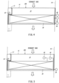
- FIG. 1 is a schematic diagram showing the heat exchanger tube block 100 according to Embodiment 1. The following will be described on the basis that regarding the directions of the heat exchanger tube block 100, upper, lower, near, deep, left, and right sides on the paper surface of FIG. 1 are respectively referred to as upper, lower, front, rear, left, and right sides.
- the heat exchanger tube block 100 constitutes part of an exhaust heat recovery boiler 101 configured to recover heat from exhaust gas.
- the heat exchanger tube block 100 is manufactured in a factory different from a construction site of the exhaust heat recovery boiler 101 and is then conveyed to the construction site.
- a plurality of heat exchanger tube blocks 100 are stacked on each other in the upper-lower direction and connected to each other.
- the exhaust heat recovery boiler 101 includes a plurality of heat exchanger tube blocks 100 stacked on each other in the upper-lower direction and connected to each other.
- the exhaust heat recovery boiler 101 is constructed by stacking a plurality of heat exchanger tube blocks 100 on each other in the upper-lower direction and connecting the plurality of heat exchanger tube blocks 100 to each other.
- the heat exchanger tube block 100 includes a duct casing 10, heat exchanger tubes 20, an inlet header 30, outlet headers 40, and a vibration transmitting member 50. The following will describe these components in order.
- the duct casing 10 constitutes part of a duct through which the exhaust gas flows. Upper and lower surfaces of the duct casing 10 are open.
- the duct casing 10 is formed in a tubular shape having a substantially rectangular section.
- the exhaust gas flows in the duct casing 10 in the upper-lower direction (downward in the present embodiment). Moreover, the exhaust gas flowing in the duct casing 10 contains a large amount of dust.
- the exhaust gas of the present embodiment is assumed to be exhaust gas generated in the process of manufacturing cement. However, the exhaust gas is not limited to this.
- a lower end of the duct casing 10 is formed horizontally, and an upper end of the duct casing 10 is also formed horizontally.
- a grounding surface which contacts a floor of a cargo bed when conveying the heat exchanger tube block 100 is the lower end of the duct casing 10, and the lower end of the duct casing 10 is formed horizontally. Therefore, the heat exchanger tube block 100 can be stably mounted on the cargo bed without using a special jig or the like. On this account, the conveying work of the heat exchanger tube block 100 can be efficiently performed.
- the duct casing 10 includes an accommodating portion 11 accommodating the heat exchanger tube 20 and a hollow portion 12 located under the heat exchanger tube 20. Since the duct casing 10 includes the hollow portion 12, an operator can enter into the hollow portion 12 and easily perform maintenance of the heat exchanger tube 20 and the inlet header 30.
- the duct casing 10 includes: an upper recess 13 located at an upper-left portion and formed such that an outer surface of the duct casing 10 is concave inward; and a lower recess 14 located at a lower-left portion and formed such that the outer surface of the duct casing 10 is concave inward.
- the upper recess 13 is formed to be open toward the upper side and the left side (outward in a horizontal direction), and the lower recess 14 is formed to be open toward the lower side and the left side (outward in the horizontal direction).
- the front and rear sides of the upper recess 13 and the front and rear sides of the lower recess 14 are closed in the present embodiment but may be open.
- the lower recess 14 is formed at a position which is located under the vibration transmitting member 50 and corresponds to the hollow portion 12. Specifically, the lower recess 14 is formed at the same height position as the hollow portion 12. Since the heat exchanger tube 20 is not provided at the hollow portion 12, the shapes and sizes of components around the hollow portion 12 can be set relatively freely. Therefore, the lower end of the duct casing 10 can be formed horizontally, and in addition, the lower recess 14 can be easily formed under the vibration transmitting member 50.
- the heat exchanger tube 20 is a member configured to transfer heat from the exhaust gas, which flows along an outer surface of the heat exchanger tube 20, to water or steam which flows in the heat exchanger tube 20.
- the heat exchanger tube 20 is arranged so as to extend horizontally, and the exhaust gas contains a large amount of dust. Therefore, when the exhaust heat recovery boiler 101 operates, the dust gradually accumulates on the heat exchanger tube 20. When the dust accumulates on the heat exchanger tube 20, a heat exchange rate significantly lowers. Therefore, as described below, in the present embodiment, the dust accumulating on the heat exchanger tube 20 is made to fall periodically by utilizing the vibration transmitting member 50.
- the inlet header 30 is a member connected to an inlet of the heat exchanger tube 20.
- the heat exchanger tube block 100 includes one inlet header 30 but may include a plurality of inlet headers 30.
- the inlet header 30 extends in the front-rear direction and is located lower than the upper end of the duct casing 10 and higher than the lower end of the duct casing 10. More specifically, the inlet header 30 is provided at the hollow portion 12 of the duct casing 10. It should be noted that the inlet header 30 may be arranged outside the duct casing 10. To be specific, the inlet header 30 is arranged at a position corresponding to the hollow portion 12, such as a position inside the hollow portion 12 or a position outside the hollow portion 12. It should be noted that the inlet header 30 may be arranged higher than the hollow portion 12. For example, as shown in FIG. 2 , the inlet header 30 may be arranged at the same height position as the heat exchanger tube 20 and outside the duct casing 10.
- Water or steam is supplied to the inlet header 30, and the supplied water or steam is distributed to the heat exchanger tubes 20.
- the water herein may denote hot water or saturated water
- the steam may denote saturated steam or superheated steam.
- the inlet header 30 can be located lower than the heat exchanger tube 20 and higher than the lower end of the duct casing 10. With this, the lower end of the duct casing 10 can be used as the grounding surface when conveying the heat exchanger tube block 100.
- Each of the outlet headers 40 is a member connected to an outlet of the heat exchanger tube 20.
- the heat exchanger tube block 100 includes two outlet headers 40 but may include one outlet header 40 or three or more outlet headers 40.
- the outlet headers 40 are located outside the duct casing 10 and at the right side of the duct casing 10.
- Each of the outlet headers 40 recovers the steam from the corresponding heat exchanger tube 20 through an inlet pipe 41 and stores the steam once. Then, the outlet header 40 discharges the steam through a discharge pipe 42 to a facility (not shown).
- both of the outlet headers 40 are located higher than the lower end of the duct casing 10 and lower than the upper end of the duct casing. Since the outlet headers 40 of the present embodiment are arranged as above, the dimension of the duct casing 10 in the upper-lower direction is equal to the dimension of the heat exchanger tube block 100 in the upper-lower direction. To be specific, according to the present embodiment, the dimension of the heat exchanger tube block 100 in the upper-lower direction can be made smaller than when the outlet headers 40 are located lower than the lower end of the duct casing 10 or higher than the upper end of the duct casing 10. As a result, the conveying work of the heat exchanger tube block 100 can be efficiently performed. It should be noted that in FIG. 1 , etc., the outlet headers 40 are located higher than the inlet header 30. However, the outlet headers 40 may be located lower than the inlet header 30.
- the vibration transmitting member 50 is a member configured to transmit vibration, applied from a vibration generator, to the heat exchanger tube 20 (not shown).
- the vibration generator may be an apparatus configured to generate vibration by utilizing a so-called striking hammer or an apparatus configured to generate vibration by utilizing ultrasound, a motor, air (soot blower), a piezoelectric element, a shock wave, or the like.
- the heat exchanger tube 20 is connected to the vibration transmitting member 50. When vibration is transferred to the heat exchanger tube 20, the heat exchanger tube 20 vibrates, and the dust accumulating on the heat exchanger tube 20 falls.
- the vibration transmitting member 50 extends upward from an inside of the duct casing 10, and an upper end part of the vibration transmitting member 50 projects to an outside of the duct casing 10.
- the upper end part of the vibration transmitting member 50 is located at the upper recess 13, and an upper end of the vibration transmitting member 50 is located higher than the upper end of the duct casing 10.
- the vibration transmitting member 50 may be arranged such that the upper end of the vibration transmitting member 50 is located lower than the upper end of the duct casing 10.
- the vibration transmitting member 50 may be formed integrally from its lower end part to its upper end part or may be formed by separate portions.
- the vibration transmitting member 50 may be formed by separate portions that are: a portion connected to the heat exchanger tube 20; and a portion including a part projecting to an outside of the duct casing 10.
- the vibration transmitting member 50 is formed by separate portions, distortion caused by thermal expansion can be suppressed.
- the vibration transmitting member 50 and the vibration generator may interfere with the heat exchanger tube block 100 adjacently located at the upper side.
- the duct casing 10 includes the lower recess 14. Therefore, when a plurality of heat exchanger tube blocks 100 are stacked on each other in the upper-lower direction, the vibration transmitting member 50 is located in the lower recess 14 of the heat exchanger tube block 100 adjacently located at the upper side.
- the vibration transmitting member 50 and the vibration generator can be prevented from interfering with the heat exchanger tube block 100 adjacently located at the upper side.
- the heat exchanger tube block 100 includes a large number of members, such as the vibration transmitting member 50. Therefore, much work, such as attaching work of the vibration transmitting member 50, at the construction site can be omitted. On this account, the assembly work of the exhaust heat recovery boiler 101 can be efficiently performed. Moreover, according to the heat exchanger tube block 100 of the present embodiment, since the lower end, formed horizontally, of the duct casing 10 serves as the grounding surface which contacts the floor of the cargo bed, the use of the special jig during conveyance can be omitted. As a result, the conveying work of the heat exchanger tube block 100 can be efficiently performed.
- FIG. 3 is a schematic diagram showing the heat exchanger tube block 200 according to Embodiment 2.
- the same reference signs are used in FIG. 3 for the same or corresponding components as in Embodiment 1, and the repetition of the same explanation is avoided.
- the upper recess 13 of the heat exchanger tube block 200 according to the present embodiment is formed larger than the upper recess 13 of the heat exchanger tube block 100 according to Embodiment 1.
- the upper end part of the vibration transmitting member 50 is located in a region defined by the upper recess 13. Therefore, the vibration transmitting member 50 is located lower than the upper end of the duct casing 10.
- the duct casing 10 of the present embodiment does not include the lower recess 14 but may include the lower recess 14.
- the hollow portion 12 is located above the heat exchanger tube 20, and the upper recess 13 is formed at the position corresponding to the hollow portion 12.
- the inlet header 30 is located outside the duct casing 10, whereas the outlet headers 40 are provided at the hollow portion 12.
- the outlet headers 40 may be located outside the duct casing 10.
- the upper end part of the vibration transmitting member 50 is located in the region defined by the upper recess 13. Therefore, when the heat exchanger tube blocks 200 are stacked on each other in the upper-lower direction, the vibration transmitting member 50 and the vibration generator can be prevented from interfering with the heat exchanger tube block 200 adjacently located at the upper side. Moreover, since the lower end of the duct casing 10 of the present embodiment is also formed horizontally as with Embodiment 1, the conveying work of the heat exchanger tube block 200 can be efficiently performed.
Landscapes
- Engineering & Computer Science (AREA)
- Mechanical Engineering (AREA)
- General Engineering & Computer Science (AREA)
- Physics & Mathematics (AREA)
- Thermal Sciences (AREA)
- Chemical & Material Sciences (AREA)
- Combustion & Propulsion (AREA)
- Heat-Exchange Devices With Radiators And Conduit Assemblies (AREA)
Applications Claiming Priority (2)
| Application Number | Priority Date | Filing Date | Title |
|---|---|---|---|
| CN201811453202.6A CN111256098B (zh) | 2018-11-30 | 2018-11-30 | 导热管块、废热回收锅炉以及废热回收锅炉的施工方法 |
| PCT/JP2019/028493 WO2020110365A1 (ja) | 2018-11-30 | 2019-07-19 | 伝熱管ブロック、排熱回収ボイラ、及び、排熱回収ボイラの施工方法 |
Publications (3)
| Publication Number | Publication Date |
|---|---|
| EP3889501A1 EP3889501A1 (en) | 2021-10-06 |
| EP3889501A4 EP3889501A4 (en) | 2022-10-05 |
| EP3889501B1 true EP3889501B1 (en) | 2024-04-10 |
Family
ID=70852752
Family Applications (1)
| Application Number | Title | Priority Date | Filing Date |
|---|---|---|---|
| EP19890878.2A Active EP3889501B1 (en) | 2018-11-30 | 2019-07-19 | Heat transmission pipe block, waste heat recovery boiler, and method for constructing waste heat recovery boiler |
Country Status (6)
| Country | Link |
|---|---|
| US (1) | US20220034502A1 (zh) |
| EP (1) | EP3889501B1 (zh) |
| JP (1) | JP7074887B2 (zh) |
| CN (1) | CN111256098B (zh) |
| ES (1) | ES2978385T3 (zh) |
| WO (1) | WO2020110365A1 (zh) |
Family Cites Families (19)
| Publication number | Priority date | Publication date | Assignee | Title |
|---|---|---|---|---|
| US1089918A (en) * | 1913-02-27 | 1914-03-10 | Frederick J Frenz | Boiler. |
| CA1012960A (en) * | 1975-09-25 | 1977-06-28 | Dominion Bridge Company | Mechanical cleaning device for boilers with gas flow containing sticky dust |
| US4203300A (en) * | 1977-10-25 | 1980-05-20 | Energy Systems Incorporated | Horizontal direct fired water bath propane vaporizer |
| US4522157A (en) * | 1982-09-30 | 1985-06-11 | Lummus Crest Inc. | Convection section assembly for process heaters |
| JP2593122B2 (ja) * | 1992-04-30 | 1997-03-26 | 新日本製鐵株式会社 | 現地小規模ブロック化によるボイラー据付工法 |
| US5238055A (en) * | 1992-05-13 | 1993-08-24 | The Babcock & Wilcox Company | Field adjustable rapper tie bar |
| DE19630482A1 (de) * | 1996-07-27 | 1998-01-29 | Metallgesellschaft Ag | Wärmeaustauscher |
| JP3817066B2 (ja) * | 1998-04-08 | 2006-08-30 | 新日本製鐵株式会社 | 伝熱管のダスト除去装置 |
| JP4234517B2 (ja) | 2003-07-25 | 2009-03-04 | 株式会社東芝 | 排熱回収ボイラ及びその据付方法 |
| CN203907577U (zh) * | 2014-04-01 | 2014-10-29 | 董磊 | 水泥窑余热锅炉省煤器管束安装结构 |
| CN104406145B (zh) * | 2014-12-15 | 2016-07-06 | 张德志 | 一种模块化立式水管余热锅炉 |
| WO2016127937A2 (zh) * | 2015-02-12 | 2016-08-18 | 安徽海螺川崎工程有限公司 | 余热锅炉 |
| CN104696937A (zh) * | 2015-02-12 | 2015-06-10 | 安徽海螺川崎工程有限公司 | 一种对废气进行热量回收的锅炉 |
| EP3086034A1 (en) * | 2015-04-20 | 2016-10-26 | General Electric Technology GmbH | Method for connecting heat exchanging surfaces to a main structure of a boiler, boiler and boiler module |
| CN105066435A (zh) * | 2015-08-18 | 2015-11-18 | 罗辉 | 一种使用甲醇燃料的立式模块锅炉 |
| CN205402660U (zh) * | 2016-03-25 | 2016-07-27 | 哈尔滨哈锅锅炉工程技术有限公司 | 一种用于卧式锅炉的模块式换热蒸发器 |
| JP6622160B2 (ja) * | 2016-09-01 | 2019-12-18 | 東邦瓦斯株式会社 | 排熱回収ボイラ |
| CN107255364A (zh) * | 2017-07-28 | 2017-10-17 | 张志村 | 一种分级逆流加热模块组合式环保节能锅炉 |
| CN209588012U (zh) * | 2018-11-30 | 2019-11-05 | 川崎重工业株式会社 | 导热管块、废热回收锅炉 |
-
2018
- 2018-11-30 CN CN201811453202.6A patent/CN111256098B/zh active Active
-
2019
- 2019-07-19 JP JP2020558079A patent/JP7074887B2/ja active Active
- 2019-07-19 EP EP19890878.2A patent/EP3889501B1/en active Active
- 2019-07-19 ES ES19890878T patent/ES2978385T3/es active Active
- 2019-07-19 WO PCT/JP2019/028493 patent/WO2020110365A1/ja unknown
- 2019-07-19 US US17/298,794 patent/US20220034502A1/en active Pending
Also Published As
| Publication number | Publication date |
|---|---|
| CN111256098A (zh) | 2020-06-09 |
| US20220034502A1 (en) | 2022-02-03 |
| CN111256098B (zh) | 2022-05-31 |
| EP3889501A4 (en) | 2022-10-05 |
| ES2978385T3 (es) | 2024-09-11 |
| WO2020110365A1 (ja) | 2020-06-04 |
| JP7074887B2 (ja) | 2022-05-24 |
| EP3889501A1 (en) | 2021-10-06 |
| JPWO2020110365A1 (ja) | 2021-09-27 |
Similar Documents
| Publication | Publication Date | Title |
|---|---|---|
| KR20100105759A (ko) | 연소 터빈 배기용 복열장치의 가요성 조립체 | |
| WO2010106699A1 (ja) | 熱交換器 | |
| JP5201729B2 (ja) | 石灰焼成プラントの廃熱回収発電プラント | |
| JP5234948B2 (ja) | 縦型熱交換器 | |
| US20090178779A1 (en) | Heat exchanger | |
| JP2006292265A (ja) | 伝熱管のダスト除去装置 | |
| WO2015001666A1 (ja) | 廃熱ボイラ | |
| KR102288553B1 (ko) | 가스-가스 열교환기 | |
| EP3889501B1 (en) | Heat transmission pipe block, waste heat recovery boiler, and method for constructing waste heat recovery boiler | |
| JP5780520B2 (ja) | 排熱回収ボイラ | |
| CN112005073B (zh) | 热交换器 | |
| JP5787154B2 (ja) | 排熱回収ボイラ | |
| CN111989531B (zh) | 传热管支承构造及传热管支承方法 | |
| CN112513525B (zh) | 锅炉装置 | |
| EP2878885B1 (en) | Internally stiffened extended service heat recovery steam generator apparatus | |
| JP4616740B2 (ja) | 循環流動層ボイラの熱交換器 | |
| JP2017166792A (ja) | 排熱回収ボイラの補修方法 | |
| JP2022117579A (ja) | 熱交換器および排煙処理システム | |
| JP2000028101A (ja) | 排熱回収ボイラの伝熱管構造 | |
| KR20240125645A (ko) | 판형 열교환기 장치, 배기 가스 열 회수에서 그 판형 열교환기 장치의 용도및 배기 가스로부터 열을 회수하기 위한 방법 |
Legal Events
| Date | Code | Title | Description |
|---|---|---|---|
| STAA | Information on the status of an ep patent application or granted ep patent |
Free format text: STATUS: THE INTERNATIONAL PUBLICATION HAS BEEN MADE |
|
| PUAI | Public reference made under article 153(3) epc to a published international application that has entered the european phase |
Free format text: ORIGINAL CODE: 0009012 |
|
| STAA | Information on the status of an ep patent application or granted ep patent |
Free format text: STATUS: REQUEST FOR EXAMINATION WAS MADE |
|
| 17P | Request for examination filed |
Effective date: 20210426 |
|
| AK | Designated contracting states |
Kind code of ref document: A1 Designated state(s): AL AT BE BG CH CY CZ DE DK EE ES FI FR GB GR HR HU IE IS IT LI LT LU LV MC MK MT NL NO PL PT RO RS SE SI SK SM TR |
|
| DAV | Request for validation of the european patent (deleted) | ||
| DAX | Request for extension of the european patent (deleted) | ||
| A4 | Supplementary search report drawn up and despatched |
Effective date: 20220905 |
|
| RIC1 | Information provided on ipc code assigned before grant |
Ipc: F22B 37/02 20060101ALI20220830BHEP Ipc: F22B 31/08 20060101ALI20220830BHEP Ipc: F28G 7/00 20060101ALI20220830BHEP Ipc: F23J 1/04 20060101ALI20220830BHEP Ipc: F22B 15/00 20060101ALI20220830BHEP Ipc: F22B 37/24 20060101AFI20220830BHEP |
|
| REG | Reference to a national code |
Ref country code: DE Ref legal event code: R079 Ref document number: 602019050244 Country of ref document: DE Free format text: PREVIOUS MAIN CLASS: F22B0037240000 Ipc: F23J0003020000 Ref country code: DE Ref legal event code: R079 Free format text: PREVIOUS MAIN CLASS: F22B0037240000 Ipc: F23J0003020000 |
|
| RIC1 | Information provided on ipc code assigned before grant |
Ipc: F28D 21/00 20060101ALI20231130BHEP Ipc: F28D 7/00 20060101ALI20231130BHEP Ipc: F22B 37/02 20060101ALI20231130BHEP Ipc: F22B 31/08 20060101ALI20231130BHEP Ipc: F28G 7/00 20060101ALI20231130BHEP Ipc: F23J 1/04 20060101ALI20231130BHEP Ipc: F22B 15/00 20060101ALI20231130BHEP Ipc: F22B 37/24 20060101ALI20231130BHEP Ipc: F23J 3/02 20060101AFI20231130BHEP |
|
| GRAP | Despatch of communication of intention to grant a patent |
Free format text: ORIGINAL CODE: EPIDOSNIGR1 |
|
| STAA | Information on the status of an ep patent application or granted ep patent |
Free format text: STATUS: GRANT OF PATENT IS INTENDED |
|
| INTG | Intention to grant announced |
Effective date: 20240122 |
|
| GRAS | Grant fee paid |
Free format text: ORIGINAL CODE: EPIDOSNIGR3 |
|
| GRAA | (expected) grant |
Free format text: ORIGINAL CODE: 0009210 |
|
| STAA | Information on the status of an ep patent application or granted ep patent |
Free format text: STATUS: THE PATENT HAS BEEN GRANTED |
|
| AK | Designated contracting states |
Kind code of ref document: B1 Designated state(s): AL AT BE BG CH CY CZ DE DK EE ES FI FR GB GR HR HU IE IS IT LI LT LU LV MC MK MT NL NO PL PT RO RS SE SI SK SM TR |
|
| REG | Reference to a national code |
Ref country code: GB Ref legal event code: FG4D |
|
| REG | Reference to a national code |
Ref country code: CH Ref legal event code: EP |
|
| REG | Reference to a national code |
Ref country code: DE Ref legal event code: R096 Ref document number: 602019050244 Country of ref document: DE |
|
| REG | Reference to a national code |
Ref country code: IE Ref legal event code: FG4D |
|
| REG | Reference to a national code |
Ref country code: GR Ref legal event code: EP Ref document number: 20240401246 Country of ref document: GR Effective date: 20240716 |
|
| REG | Reference to a national code |
Ref country code: LT Ref legal event code: MG9D |
|
| REG | Reference to a national code |
Ref country code: NL Ref legal event code: MP Effective date: 20240410 |
|
| REG | Reference to a national code |
Ref country code: ES Ref legal event code: FG2A Ref document number: 2978385 Country of ref document: ES Kind code of ref document: T3 Effective date: 20240911 |
|
| REG | Reference to a national code |
Ref country code: AT Ref legal event code: MK05 Ref document number: 1675243 Country of ref document: AT Kind code of ref document: T Effective date: 20240410 |