EP3885276B1 - Beutelherstellungs- und -verpackungsvorrichtung - Google Patents
Beutelherstellungs- und -verpackungsvorrichtung Download PDFInfo
- Publication number
- EP3885276B1 EP3885276B1 EP21163931.5A EP21163931A EP3885276B1 EP 3885276 B1 EP3885276 B1 EP 3885276B1 EP 21163931 A EP21163931 A EP 21163931A EP 3885276 B1 EP3885276 B1 EP 3885276B1
- Authority
- EP
- European Patent Office
- Prior art keywords
- printing
- bag
- mode
- film
- making
- Prior art date
- Legal status (The legal status is an assumption and is not a legal conclusion. Google has not performed a legal analysis and makes no representation as to the accuracy of the status listed.)
- Active
Links
- 238000004806 packaging method and process Methods 0.000 title claims description 207
- 238000007639 printing Methods 0.000 claims description 478
- 239000005022 packaging material Substances 0.000 claims description 97
- 230000007246 mechanism Effects 0.000 description 77
- 238000007789 sealing Methods 0.000 description 64
- 230000000717 retained effect Effects 0.000 description 27
- 239000004973 liquid crystal related substance Substances 0.000 description 22
- 238000007689 inspection Methods 0.000 description 15
- 230000004048 modification Effects 0.000 description 14
- 238000012986 modification Methods 0.000 description 14
- 238000007493 shaping process Methods 0.000 description 14
- 238000005303 weighing Methods 0.000 description 14
- 238000004519 manufacturing process Methods 0.000 description 13
- 235000013305 food Nutrition 0.000 description 6
- 230000008859 change Effects 0.000 description 5
- 239000000470 constituent Substances 0.000 description 5
- 238000005520 cutting process Methods 0.000 description 4
- 238000000034 method Methods 0.000 description 4
- 230000008569 process Effects 0.000 description 4
- 230000000694 effects Effects 0.000 description 3
- 230000009471 action Effects 0.000 description 2
- 238000010586 diagram Methods 0.000 description 2
- 230000003287 optical effect Effects 0.000 description 2
- 238000003825 pressing Methods 0.000 description 2
- 238000009751 slip forming Methods 0.000 description 2
- 238000005452 bending Methods 0.000 description 1
- 230000007547 defect Effects 0.000 description 1
- 230000007123 defense Effects 0.000 description 1
- 238000006073 displacement reaction Methods 0.000 description 1
- 238000010438 heat treatment Methods 0.000 description 1
- 238000009434 installation Methods 0.000 description 1
- 238000000926 separation method Methods 0.000 description 1
- 238000011144 upstream manufacturing Methods 0.000 description 1
Images


Classifications
-
- B—PERFORMING OPERATIONS; TRANSPORTING
- B65—CONVEYING; PACKING; STORING; HANDLING THIN OR FILAMENTARY MATERIAL
- B65B—MACHINES, APPARATUS OR DEVICES FOR, OR METHODS OF, PACKAGING ARTICLES OR MATERIALS; UNPACKING
- B65B9/00—Enclosing successive articles, or quantities of material, e.g. liquids or semiliquids, in flat, folded, or tubular webs of flexible sheet material; Subdividing filled flexible tubes to form packages
- B65B9/10—Enclosing successive articles, or quantities of material, in preformed tubular webs, or in webs formed into tubes around filling nozzles, e.g. extruded tubular webs
- B65B9/20—Enclosing successive articles, or quantities of material, in preformed tubular webs, or in webs formed into tubes around filling nozzles, e.g. extruded tubular webs the webs being formed into tubes in situ around the filling nozzles
- B65B9/207—Enclosing successive articles, or quantities of material, in preformed tubular webs, or in webs formed into tubes around filling nozzles, e.g. extruded tubular webs the webs being formed into tubes in situ around the filling nozzles the web advancing continuously
-
- B—PERFORMING OPERATIONS; TRANSPORTING
- B41—PRINTING; LINING MACHINES; TYPEWRITERS; STAMPS
- B41M—PRINTING, DUPLICATING, MARKING, OR COPYING PROCESSES; COLOUR PRINTING
- B41M5/00—Duplicating or marking methods; Sheet materials for use therein
- B41M5/0041—Digital printing on surfaces other than ordinary paper
-
- B—PERFORMING OPERATIONS; TRANSPORTING
- B65—CONVEYING; PACKING; STORING; HANDLING THIN OR FILAMENTARY MATERIAL
- B65B—MACHINES, APPARATUS OR DEVICES FOR, OR METHODS OF, PACKAGING ARTICLES OR MATERIALS; UNPACKING
- B65B57/00—Automatic control, checking, warning, or safety devices
- B65B57/02—Automatic control, checking, warning, or safety devices responsive to absence, presence, abnormal feed, or misplacement of binding or wrapping material, containers, or packages
- B65B57/04—Automatic control, checking, warning, or safety devices responsive to absence, presence, abnormal feed, or misplacement of binding or wrapping material, containers, or packages and operating to control, or to stop, the feed of such material, containers, or packages
-
- B—PERFORMING OPERATIONS; TRANSPORTING
- B65—CONVEYING; PACKING; STORING; HANDLING THIN OR FILAMENTARY MATERIAL
- B65B—MACHINES, APPARATUS OR DEVICES FOR, OR METHODS OF, PACKAGING ARTICLES OR MATERIALS; UNPACKING
- B65B61/00—Auxiliary devices, not otherwise provided for, for operating on sheets, blanks, webs, binding material, containers or packages
- B65B61/02—Auxiliary devices, not otherwise provided for, for operating on sheets, blanks, webs, binding material, containers or packages for perforating, scoring, slitting, or applying code or date marks on material prior to packaging
- B65B61/025—Auxiliary devices, not otherwise provided for, for operating on sheets, blanks, webs, binding material, containers or packages for perforating, scoring, slitting, or applying code or date marks on material prior to packaging for applying, e.g. printing, code or date marks on material prior to packaging
-
- B—PERFORMING OPERATIONS; TRANSPORTING
- B65—CONVEYING; PACKING; STORING; HANDLING THIN OR FILAMENTARY MATERIAL
- B65B—MACHINES, APPARATUS OR DEVICES FOR, OR METHODS OF, PACKAGING ARTICLES OR MATERIALS; UNPACKING
- B65B9/00—Enclosing successive articles, or quantities of material, e.g. liquids or semiliquids, in flat, folded, or tubular webs of flexible sheet material; Subdividing filled flexible tubes to form packages
- B65B9/06—Enclosing successive articles, or quantities of material, in a longitudinally-folded web, or in a web folded into a tube about the articles or quantities of material placed upon it
- B65B9/08—Enclosing successive articles, or quantities of material, in a longitudinally-folded web, or in a web folded into a tube about the articles or quantities of material placed upon it in a web folded and sealed transversely to form pockets which are subsequently filled and then closed by sealing
- B65B9/093—Enclosing successive articles, or quantities of material, in a longitudinally-folded web, or in a web folded into a tube about the articles or quantities of material placed upon it in a web folded and sealed transversely to form pockets which are subsequently filled and then closed by sealing the web having intermittent motion
-
- B—PERFORMING OPERATIONS; TRANSPORTING
- B65—CONVEYING; PACKING; STORING; HANDLING THIN OR FILAMENTARY MATERIAL
- B65B—MACHINES, APPARATUS OR DEVICES FOR, OR METHODS OF, PACKAGING ARTICLES OR MATERIALS; UNPACKING
- B65B9/00—Enclosing successive articles, or quantities of material, e.g. liquids or semiliquids, in flat, folded, or tubular webs of flexible sheet material; Subdividing filled flexible tubes to form packages
- B65B9/10—Enclosing successive articles, or quantities of material, in preformed tubular webs, or in webs formed into tubes around filling nozzles, e.g. extruded tubular webs
- B65B9/20—Enclosing successive articles, or quantities of material, in preformed tubular webs, or in webs formed into tubes around filling nozzles, e.g. extruded tubular webs the webs being formed into tubes in situ around the filling nozzles
- B65B9/213—Enclosing successive articles, or quantities of material, in preformed tubular webs, or in webs formed into tubes around filling nozzles, e.g. extruded tubular webs the webs being formed into tubes in situ around the filling nozzles the web having intermittent motion
Definitions
- the present invention relates to a bag-making and packaging apparatus.
- a bag-making and packaging apparatus to manufacture a bag in which an article is packaged by transversely sealing a cylindrically shaped packaging material as disclosed in Patent Literature 1 (Japanese Patent Unexamined Publication JP 2012-136270 A ), is conventionally known.
- the bag-making and packaging apparatus is provided with a printing device to print pre-set information on the packaging material prior to shaping thereof into a cylindrical shape, and a platen which is arranged so as to face a print head of the printing device.
- EP 3246262 A1 discloses a bag making and packaging machine provided with a feed mechanism, a roll holding portion, a printing mechanism, a former, a longitudinal seal mechanism, a transverse seal mechanism, a cutting mechanism, a first sensor, and a second sensor.
- the printing mechanism prints information on a film.
- the former causes the two longitudinal sides of the film to become overlapped.
- the longitudinal seal mechanism bonds the two longitudinal sides and makes a film tube.
- the transverse seal mechanism sandwiches and bonds the film tube and makes a transverse seal portion.
- the cutting mechanism cuts the film tube at the transverse seal portion.
- the first sensor detects a mark on the film for identifying a cutting position for cutting the film tube.
- the second sensor detects a mark for specifying a printing position of the film where predetermined information is to be printed.
- Bag-making and packaging apparatuses are classified mainly as continuous-type packaging machines in which transverse sealing is performed while the packaging material is continuously conveyed, and intermittent-type packaging machines in which transverse sealing is performed while the packaging material is intermittently conveyed.
- the printing device of a continuous-type packaging machine prints on the packaging material during conveyance thereof, without stopping conveyance of the packaging material.
- the printing device of an intermittent-type packaging machine prints on the packaging material while the packaging material is stopped, at a timing at which conveyance of the packaging material is stopped.
- a continuous-type packaging machine is a superior model, obtained by making an intermittent-type packaging machine capable of continuous conveyance of the packaging material.
- a transverse sealing mechanism of the continuous-type packaging machine is backwards-compatible with the transverse sealing mechanism of the intermittent-type packaging machine. Therefore, using a single transverse sealing mechanism, a bag-making and packaging apparatus can be configured so as to be capable of switching between a continuous mode for performing transverse sealing while continuously conveying the packaging material, and an intermittent mode for performing transverse sealing while intermittently conveying the packaging material.
- the platen used in the continuous-type packaging machine and the platen used in the intermittent-type packaging machine have mutually different shapes. For this reason, in a bag-making and packaging apparatus that is capable of switching between a continuous mode and an intermittent mode, it is necessary to mount both a set of the platen and printing device used in the continuous-type packaging machine, and a set of the platen and printing device used in the intermittent-type packaging machine. In this case, costs are incurred from the need to secure space for installing two identical printing devices.
- An object of the present invention is to provide a bag-making and packaging apparatus in which an operating mode can be switched, and a platen used in each operating mode can easily be switched.
- a bag-making and packaging apparatus forms a bag in which an article is packaged from a packaging material, while conveying the packaging material.
- the bag-making and packaging apparatus comprises a printing part, a first receiving part, a second receiving part, and a retaining part.
- the printing part prints predetermined information on the packaging material before the bag is formed.
- the first receiving part is used in a first printing mode to print on the packaging material during conveyance thereof, without stopping conveyance of the packaging material.
- the second receiving part is used in a second printing mode to print on the stopped packaging material at a timing at which conveyance of the packaging material is stopped.
- the retaining part retains at least one of the first receiving part and the second receiving part.
- the retaining part retains at least one of the first receiving part and the second receiving part so that the first receiving part and the printing part face each other with the packaging material disposed therebetween in the first printing mode, and the second receiving part and the printing part face each other with the packaging material disposed therebetween in the second printing mode.
- printing on the packaging material is performed using the first receiving part when in the continuous mode in which a bag is continuously formed while the packaging material is continuously conveyed, and printing on the packaging material is performed using the second receiving part when in the intermittent mode in which a bag is formed while the packaging material is intermittently conveyed.
- the receiving part used during printing on the packaging material can easily be switched in accordance with the operating mode.
- a bag-making and packaging apparatus forms a bag in which an article is packaged from a packaging material, while conveying the packaging material.
- the bag-making and packaging apparatus comprises a printing part, a first receiving part, a second receiving part, and a switching part.
- the printing part prints predetermined information on the packaging material before the bag is formed.
- the first receiving part is used for printing on the packaging material during conveyance thereof, without stopping conveyance of the packaging material.
- the second receiving part is used for printing on the stopped packaging material at a timing at which conveyance of the packaging material is stopped.
- the switching part switches between a first printing state in which the first receiving part and the printing part face each other with the packaging material disposed therebetween, and a second printing state in which the second receiving part and the printing part face each other with the packaging material disposed therebetween.
- printing on the packaging material is performed using the first receiving part when in the continuous mode in which a bag is continuously formed while the packaging material is continuously conveyed, and printing on the packaging material is performed using the second receiving part when in the intermittent mode in which a bag is formed while the packaging material is intermittently conveyed.
- the receiving part used during printing on the packaging material can easily be switched in accordance with the operating mode.
- a bag-making and packaging apparatus is the bag-making and packaging apparatus according to the second aspect, wherein the switching part switches between the first printing state and the second printing state by causing at least one of the first receiving part and the second receiving part to move.
- a bag-making and packaging apparatus is the bag-making and packaging apparatus according to the second aspect, wherein the switching part switches between the first printing state and the second printing state by causing the printing part to move.
- a bag-making and packaging apparatus is the bag-making and packaging apparatus according to the fourth aspect, wherein the switching part causes the printing part to move along the packaging material.
- a bag-making and packaging apparatus is the bag-making and packaging apparatus according to any one of the second through fifth aspects, further comprising a conveyance roller for sending the packaging material between the first receiving part and the printing part, or between the second receiving part and the printing part.
- the switching part switches between the first printing state and the second printing state by causing the conveyance roller to move.
- a bag-making and packaging apparatus is the bag-making and packaging apparatus according to any one of the first through fifth aspects, wherein the first receiving part is a cylindrical member, and the second receiving part is a flat-plate-shaped member.
- a bag-making and packaging apparatus is the bag-making and packaging apparatus according to the first or second aspect, further comprising a control unit.
- the control unit controls operation of the printing part on the basis of predetermined information inputted in advance.
- the printing part has the first printing mode and the second printing mode as selectable printing modes for printing on the packaging material.
- the control unit switches the printing mode to the first printing mode when it is determined that the timing of printing on the packaging material is during conveyance of the packaging material, on the basis of the predetermined information.
- the control unit switches the printing mode to the second printing mode when it is determined that the timing of printing on the packaging material is during stoppage of the packaging material, on the basis of the predetermined information.
- the printing mode is decided according to the timing of printing on the packaging material regardless of whether bags are manufactured continuously or intermittently, there is no need for the operator to be conscious of which printing mode to operate in, and the printing mode that is suited for production is selected, thereby preventing misoperation.
- a bag-making and packaging apparatus is the bag-making and packaging apparatus according to the first or second aspect, further comprising a control unit and an instruction unit.
- the control unit controls operation of the printing part.
- the printing part has the first printing mode and the second printing mode as a plurality of selectable printing modes for printing on the packaging material.
- the instruction unit instructs the control unit to switch the printing mode.
- the control unit switches the printing mode to the first printing mode when it is determined that the timing of printing on the packaging material is during conveyance of the packaging material, on the basis of predetermined information inputted in advance and an instruction from the instruction unit.
- the control unit switches the printing mode to the second printing mode when it is determined that the timing of printing on the packaging material is during stoppage of the packaging material, on the basis of predetermined information inputted in advance and an instruction from the instruction unit.
- a bag-making and packaging apparatus is the bag-making and packaging apparatus according to the eighth or ninth aspect, wherein the control unit has, as selectable conveyance modes for conveying the packaging material, a first conveyance mode and a second conveyance mode.
- the first conveyance mode is a mode to continuously convey the packaging material.
- the second conveyance mode is a mode to intermittently convey the packaging material.
- the predetermined information includes a result of selecting the conveyance mode.
- a bag-making and packaging apparatus is the bag-making and packaging apparatus according to the tenth aspect, wherein the control unit switches the printing mode to the first printing mode when the conveyance mode is the second conveyance mode and it is determined that the timing of printing on the packaging material is during conveyance of the packaging material.
- the printing mode is switched according to whether the printing timing is during conveyance or during stopping of the packaging material, even in the second (intermittent) conveyance mode, rather than simply switching to the first printing mode when in the first conveyance mode (continuous), or switching to the second printing mode when in the second conveyance mode (intermittent).
- the printing mode that is suited for production is therefore selected.
- the receiving part that is used during printing on the packaging material can easily be switched in accordance with the operating mode.
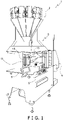
- FIG 1 is a perspective view of a bag-making and packaging apparatus 1 according to a first embodiment of the present invention.
- the bag-making and packaging apparatus 1 is a machine for bagging a food product or other package contents.
- the bag-making and packaging apparatus 1 is configured mainly from a combination weighing unit 2, a bag-making and packaging unit 3, and film supply unit 4.
- the combination weighing unit 2 is arranged above the bag-making and packaging unit 3.
- the combination weighing unit 2 weighs out the weight of package contents with a plurality of weighing hoppers, and combines the weights measured in each of the weighing hoppers, to arrive at a prescribed total weight.
- the combination weighing unit 2 then downwardly discharges the package contents, in the prescribed combined total weight, to supply the package contents to the bag-making and packaging unit 3.
- the bag-making and packaging unit 3 seals package contents into a bag to form a package in accordance with the timing at which the package contents are supplied from the combination weighing unit 2.
- the detailed configuration and action of the bag-making and packaging unit 3 will be discussed below.
- the film supply unit 4 is arranged adjacent to the bag-making and packaging unit 3, and supplies a film to be shaped into a bag to the bag-making and packaging unit 3.
- a film roll onto which the film is wound is installed in the film supply unit 4.
- the film supply unit 4 reels out the film from a film roll. The detailed configuration and action of the film supply unit 4 will be discussed below.
- the bag-making and packaging apparatus 1 is provided with an operation switch 5 and a liquid crystal display 6.
- the operation switch 5 and the liquid crystal display 6 are mounted to the front surface of the body of the bag-making and packaging apparatus 1.
- the liquid crystal display 6 is a touch panel display arranged at a location visible to the operator of the operation switch 5.
- the operation switch 5 and the liquid crystal display 6 function as input devices for receiving instructions for the bag-making and packaging apparatus 1, and settings relating to the bag-making and packaging apparatus 1.
- the liquid crystal display 6 also functions as an output device for displaying information relating to the bag-making and packaging apparatus 1.
- the bag-making and packaging apparatus 1 is provided with a control unit (not illustrated).
- the control unit is a computer configured from a CPU, ROM, RAM, and the like.
- the control unit is connected to the combination weighing unit 2, the bag-making and packaging unit 3, the film supply unit 4, the operation switch 5, and the liquid crystal display 6.
- the control unit controls the combination weighing unit 2, the bag-making and packaging unit 3, and the film supply unit 4, and outputs information of various kinds to the liquid crystal display 6.
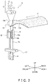
- FIG. 2 is a perspective view showing a simplified configuration of the bag-making and packaging unit 3.
- the six directions “front (front surface),” “back (back surface),” “up,” “down,” “left,” and “right” are defined as shown in FIG. 2 .
- the bag-making and packaging unit 3 is configured mainly from a shaping mechanism 13, a pull-down belt mechanism 14, a longitudinal sealing mechanism 15, and a transverse sealing mechanism 17.
- the shaping mechanism 13 shapes a sheet-shaped film F, which is supplied from the film supply unit 4, into a tube shape.
- the pull-down belt mechanism 14 conveys the cylindrically shaped film F downward.
- the longitudinal sealing mechanism 15 seals, in a longitudinal direction parallel to the conveying direction, portions where both edges of the cylindrically shaped film F overlap, and forms a cylindrical film Fc.
- the transverse sealing mechanism 17 seals the cylindrical film Fc in a transverse direction orthogonal to the conveying direction, forming bags B which are sealed at their top edge portion and bottom edge portion.
- the bag-making and packaging apparatus 1 has two operating modes, consisting of a continuous mode in which bags B are formed while the film F is continuously conveyed, and an intermittent mode in which bags B are formed while the film F is intermittently conveyed.
- the continuous mode is an operating mode in which bags B are formed without stopping conveyance of the film F.
- the intermittent mode is an operating mode in which bags B are formed while conveyance of the film F is temporarily stopped at a predetermined timing.
- the bag-making and packaging unit 3 seals the film F as the film F is being conveyed.
- the bag-making and packaging unit 3 seals stopped film F at the timing at which conveyance of the film F is stopped.
- the control unit of the bag-making and packaging apparatus 1 controls the bag-making and packaging unit 3 in accordance with the operating mode.
- the shaping mechanism 13 has a tube 13a and a former 13b.
- the tube 13a is a round cylindrical member open at the top end and the bottom end.
- Package contents C supplied from the combination weighing unit 2 are charged into the opening at the top end of the tube 13a.
- the former 13b is arranged so as to encircle the tube 13a. As the film F reeled out from the film roll of the film supply unit 4 passes through a gap between the tube 13a and the former 13b, the film wraps about the tube 13a to form a tube shape.
- the tube 13a and the former 13b can be swapped out according to the size of the bags B being manufactured.
- the pull-down belt mechanism 14 conveys downward the film F, which has wrapped about the tube 13a, while holding the film under suction.
- the pull-down belt mechanism 14 has mainly a drive roller 14a, a driven roller 14b, and a pair of belts 14c.
- the pair of belts 14c are arranged so as to sandwich the tube 13a on the left and right sides of the tube 13a as shown in Figure 2 , and have a mechanism for holding the cylindrically shaped film F under suction.
- the pull-down belt mechanism 14 conveys the cylindrically shaped film F downward, due to the pair of belts 14c being rotatably driven by the drive roller 14a and the driven roller 14b.
- the longitudinal sealing mechanism 15 seals the cylindrically shaped film F in the longitudinal direction (the vertical direction in FIG. 2 ).
- the longitudinal sealing mechanism 15 is arranged on the front surface side of the tube 13a.
- a drive mechanism (not illustrated) moves the longitudinal sealing mechanism 15 in the forward-backward direction so as to approach or move away from the tube 13a.
- the longitudinal sealing mechanism 15 By driving the longitudinal sealing mechanism 15 closer to the tube 13a using the drive mechanism, longitudinal-direction overlapping portions of the film F wrapped about the tube 13a are sandwiched between the longitudinal sealing mechanism 15 and the tube 13a.
- the overlapping portions of the film F are heated while being pressed against the tube 13a under fixed pressure by the drive mechanism, heat-sealing the overlapping portions of the film F in the longitudinal-direction and forming a cylindrical film Fc.
- the longitudinal sealing mechanism 15 has a heater for heating the overlapping portions of the film F, a heater belt that contacts the overlapping portions of the film F, and the like.
- the transverse sealing mechanism 17 seals the cylindrical film Fc in the transverse direction (the left-right direction in FIG. 2 ).
- the transverse sealing mechanism 17 is arranged below the shaping mechanism 13, the pull-down belt mechanism 14, and the longitudinal sealing mechanism 15.
- FIG. 3 is a simplified side view of the transverse sealing mechanism 17 as seen from the right side of FIG. 2 .
- the direction perpendicular to the image plane in FIG. 3 is the left-right direction in FIG. 2 .
- the transverse sealing mechanism 17 comprises mainly a first rotating body 50a and a second rotating body 50b.
- the first rotating body 50a is arranged on the front side of the cylindrical film Fc.
- the second rotating body 50b is arranged on the rear side of the cylindrical film Fc.
- the first rotating body 50a is positioned on the left side of the cylindrical film Fc
- the second rotating body 50b is positioned on the right side of the cylindrical film Fc.
- the first rotating body 50a comprises mainly a first rotating shaft 53a, a first sealing jaw 51a, and a second sealing jaw 52a.
- the second rotating body 50b comprises mainly a second rotating shaft 53b, a first sealing jaw 51b, and a second sealing jaw 52b.
- the first rotating shaft 53a as a rotating shaft
- the first rotating body 50a rotates about a rotational center C1 of the first rotating shaft 53a, as seen along the left-right direction.
- the second rotating shaft 53b as a rotating shaft
- the second rotating body 50b rotates about the rotational center C2 of the second rotating shaft 53b, as seen along the left-right direction.
- the cylindrical film Fc is sandwiched along the transverse direction (the left-right direction in FIG. 2 ) intersecting with the conveying direction of the cylindrical film Fc by the pair of first sealing jaws 51a, 51b or the pair of second sealing jaws 52a, 52b.
- the pair of first sealing jaws 51a, 51b or the pair of second sealing jaws 52a, 52b heat the cylindrical film Fc while sandwiching the cylindrical film Fc, and thereby heat-seal the cylindrical film Fc in the transverse direction.
- Figures 4 and 5 are side views showing a simplified configuration of the film supply unit 4 of the present embodiment.
- the sheet-shaped film F is conveyed from right (upstream) to left (downstream).
- the conveying direction of the film F is indicated by arrows in FIGS. 4 and 5 .
- Figure 4 illustrates a configuration in the continuous mode.
- Figure 5 illustrates a configuration in the intermittent mode.
- the film supply unit 4 reels out the film F from a film roll FR, prints predetermined information on the surface of the film F, and supplies the film F to the shaping mechanism 13 of the bag-making and packaging unit 3.
- the film supply unit 4 comprises mainly an air shaft 21, a plurality of tension rollers 22, a printing device 23, an inspection device 24, and feed rollers 25, 26.
- the film supply unit 4 continuously reels out the film F from the film roll FR.
- the film supply unit 4 intermittently reels out the film F from the film roll FR.
- the control unit of the bag-making and packaging apparatus 1 controls the film supply unit 4 in accordance with the operating mode.
- the air shaft 21 is a shaft on which the film roll FR is set, the sheet-shaped film F being wound onto the film roll FR.
- the film roll FR is secured by vacuum suction to the air shaft 21.
- the air shaft 21 is rotatably driven by a shaft drive motor (not illustrated). The shaft drive motor causes the air shaft 21 to rotate, and the sheet-shaped film F wound onto the film roll FR is thereby reeled out.
- the film F reeled out from the film roll FR in the film supply unit 4 is ultimately sent to the bag-making and packaging unit 3.
- the film F is shaped into a tube shape by the shaping mechanism 13 and is conveyed downward by the pull-down belt mechanism 14.
- the amount of the film F that is reeled out from the film roll FR is thereby conveyed in the film supply unit 4.
- the control unit controls the shaft drive motor to change the rotation speed of the air shaft 21, and the conveyance speed of the film F reeled out from the film roll FR can thereby be adjusted.
- the tension rollers 22 are arranged in predetermined positions at a predetermined separation interval.
- the tension rollers 22 guide the film F to the printing device 23 while bending the film F reeled out from the film roll FR to vary the conveyance angle thereof.
- the tension rollers 22 apply an appropriate tension to the film F that is reeled out from the film roll FR and conveyed, and prevent slackness and meandering of the conveyed film F.
- the number and positioning of the tension rollers 22 can be arbitrarily set in accordance with the position of the film roll FR, the dimensions of the film F and the like.
- At least some of the tension rollers 22 may be movable in the vertical direction.
- the tension on the film F that is guided by the tension rollers 22 can be adjusted by moving the tension rollers 22.
- the control unit detects the tension state of the film F on the basis of the amount of vertical displacement of the tension rollers 22. On the basis of the detected tension state, the control unit then controls the shaft drive motor to adjust the conveyance speed of the film F so that the tension on the film F is within a predetermined range.
- the printing device 23 comprises mainly a print head 23a and a retaining part 23b.
- the print head 23a prints predetermined printing information on the surface of the film F.
- the printing information is printed in a predetermined printing region on the surface of the film F.
- the printing information is transmitted from the control unit to the printing device 23.
- the print head 23a can move along the direction toward the film F or away from the film F during printing of the printing information.
- the retaining part 23b retains platens 23c, 23d.
- the platens 23c, 23d are members for receiving the film F.
- the print head 23a presses the film F toward the platens 23c, 23d.
- the platens 23c, 23d are formed from rubber or another elastic member, for example.
- a platen roller 23c and a platen plate 23d are used as the platens 23c, 23d.
- the platen roller 23c In the continuous mode, the platen roller 23c is used. In the intermittent mode, the platen plate 23d is used.
- the retaining part 23b retains either a platen roller 23c or a platen plate 23d. In FIG. 4 , the retaining part 23b retains the platen roller 23c. In FIG. 5 , the retaining part 23b retains the platen plate 23d.
- the platens 23c, 23d retained by the retaining part 23b are arranged facing the print head 23a at a position in which the film F is disposed between the platens 23c, 23d and the print head 23a.
- the film F reeled out from the film roll FR and conveyed passes between the print head 23a and the platens 23c, 23d, and is sent to the bag-making and packaging unit 3. While the print head 23a is pressing the film F toward the platens 23c, 23d, the film F is disposed between the print head 23a and the platens 23c, 23d.
- the retaining part 23b retains at least one of the platen roller 23c and the platen plate 23d so that the platen roller 23c and the print head 23a face each other in the continuous mode (first printing mode), and so that the platen plate 23d and the print head 23a face each other in the intermittent mode (second printing mode).
- the inspection device 24 is arranged in the vicinity of a downstream side of the printing device 23.
- the inspection device 24 inspects whether the printing information in the printing region of the film F is correctly printed.
- the inspection device 24 is an optical sensor constituted from a light-emitting element and a light-receiving element.
- the conveyed film F passes between the light-emitting element and the light-receiving element.
- the light-emitting element radiates light to the printing region of the film F.
- the light-receiving element senses light that is reflected by the printing region and detects the position of the printing information printed in the printing region and the like.
- the inspection device 24 may also be an optical camera. In this case, the inspection device 24 inspects whether the printing information is correctly printed in the printing region by capturing an image of the printing region of the conveyed film F and analyzing the acquired image.
- the feed rollers 25, 26 guide the film F conveyed in the film supply unit 4 in a predetermined direction.
- a first feed roller 25 and a second feed roller 26 are used as the feed rollers 25, 26.
- the first feed roller 25 is arranged between the tension rollers 22 and the printing device 23 in the path in which the film F is conveyed, and guides the film F in the direction of the printing device 23.
- the first feed roller 25 guides the film F between the print head 23a and the platens 23c, 23d.
- the second feed roller 26 is arranged between the printing device 23 and the inspection device 24 in the path in which the film F is conveyed, and guides the film F in the direction of the inspection device 24.
- the positions of the feed rollers 25, 26 in the continuous mode are different from the positions of the feed rollers 25, 26 in the intermittent mode.
- the positions of the feed rollers 25, 26 are controlled by an air cylinder or other drive mechanism (not illustrated).
- the control unit automatically switches the positions of the feed rollers 25, 26 in accordance with the operating mode.
- the number and positioning of the feed rollers 25, 26 can be arbitrarily set in accordance with the configuration of the film supply unit 4 and the like. Depending upon the configuration of the film supply unit 4, the film supply unit 4 need not be provided with the feed rollers 25, 26.
- the operation whereby the bag-making and packaging apparatus 1 seals package contents C in a bag B is summarized below.
- the film F supplied to the bag-making and packaging unit 3 from the film supply unit 4 is wrapped about the tube 13a and shaped into a tube shape, and is conveyed downward by the pull-down belt mechanism 14.
- the film F, in the shape of a cylinder wrapped about the tube 13a, is made to overlap at both ends extending in the up-down direction.
- the overlapping portions of the cylindrically shaped film F are sealed in the longitudinal direction by the longitudinal sealing mechanism 15, forming the cylindrical film Fc.
- the longitudinally sealed cylindrical film Fc is removed from the tube 13a and conveyed downward to the transverse sealing mechanism 17.
- the transverse sealing mechanism 17 sandwiches and transversely seals the cylindrical film Fc.
- a bag B in which package contents C are enclosed is formed below the transversely sealed portion of the cylindrical film Fc.
- package contents C weighed out by the combination weighing unit 2 are dropped into the tube 13a and charged into the cylindrical film Fc.
- the transversely sealed portion of the cylindrical film Fc is cut in the transverse direction by a cutter (not illustrated) which is built into the first sealing jaw 51a or the second sealing jaw 52a, in accordance with the timing at which the cylindrical film Fc is transversely sealed. In so doing, the bag B in which the package contents C are sealed is cut away from the trailing cylindrical film Fc.
- bags B in which the package contents C are sealed are manufactured continuously.
- the manufactured bags B are then transported to a thickness checker, a weight checker, and other devices by a belt conveyor (not illustrated) or the like.
- the bag-making and packaging apparatus 1 may also make bags in a form in which a plurality of bags B are linked in a continuous package.
- the transversely sealed portion of the cylindrical film Fc is cut in the transverse direction each time that a predetermined number of bags B are formed by the transverse sealing mechanism 17.
- the bag-making and packaging apparatus 1 of the present embodiment operates in either a continuous operating mode or an intermittent operating mode.
- the transverse sealing mechanism 17 transversely seals the cylindrical film Fc under conveyance while the transverse sealing mechanism 17 moves downward in accordance with the downward conveyance of the cylindrical film Fc.
- the transverse sealing mechanism 17 transversely seals the stopped cylindrical film Fc.
- the bag-making and packaging apparatus 1 is configured so that the operating mode can be switched between the continuous mode and the intermittent mode. For example, when the bag-making and packaging apparatus 1 is making bags in the form of a continuous package as described above and the manufacturing capacity thereof is increased, manufacturing capacity may sometimes be higher in the intermittent mode than in the continuous mode. Therefore, by making it possible to switch between the continuous mode and the intermittent mode, an operator of the bag-making and packaging apparatus 1 is enabled to select the appropriate operating mode in accordance with the situation.
- the film supply unit 4 reels out and conveys the film F from the film roll FR fixed to the air shaft 21, and supplies the film F to the shaping mechanism 13 of the bag-making and packaging unit 3.
- the film supply unit 4 conveys the film F reeled out from the film roll FR while guiding the film F in the tension rollers 22.
- the film F is guided in the direction of the printing device 23 by the first feed roller 25 in the film supply unit 4.
- the printing information is then printed in the printing region of the film F by the printing device 23 in the film supply unit 4.
- the film F is then guided in the direction of the inspection device 24 by the second feed roller 26 in the film supply unit 4.
- the film supply unit 4 inspects whether the printing information in the printing region of the film F is correctly printed.
- the film supply unit 4 then sends the film F to the shaping mechanism 13 of the bag-making and packaging unit 3.
- first printing mode while the printing device 23 is printing in the printing region of the film F, the film F is conveyed and the print head 23a does not move along the conveyance direction of the film F.
- intermittent mode while the printing device 23 is printing in the printing region of the film F, conveyance of the film F is stopped and the print head 23a moves along the conveyance direction of the film F. In this manner, in both the continuous mode and the intermittent mode, the print head 23a moves relative to the film F in the conveyance direction of the film F, and the printing information is thereby printed in the printing region of the film F.
- the bag-making and packaging apparatus 1 it is possible to switch between the continuous mode and the intermittent mode.
- the bag-making and packaging apparatus 1 can use the same bag-making and packaging unit 3 in both the continuous operating mode and the intermittent operating mode.
- the printing device 23 of the film supply unit 4 uses the platen roller 23c in the continuous mode, and uses the platen plate 23d in the intermittent mode.
- the bag-making and packaging apparatus 1 therefore has a retaining part 23b to make it possible to use the platen 23c, 23d that is appropriate in accordance with the operating mode.
- the retaining part 23b is configured so as to be capable of retaining the platen roller 23c or the platen plate 23d in the appropriate position in accordance with the operating mode of the bag-making and packaging apparatus 1.
- the retaining part 23b retains the platen roller 23c so that the print head 23a and the platen roller 23c face each other with the film F disposed therebetween.
- the retaining part 23b retains the platen plate 23d so that the print head 23a and the platen plate 23d face each other with the film F disposed therebetween.
- the platen roller 23c and the platen plate 23d are configured so as to be attachable to and detachable from the retaining part 23b.
- An operator of the bag-making and packaging apparatus 1 can thereby change the platen 23c, 23d that is retained by the retaining part 23b when switching the operating mode. For example, when switching from the continuous mode to the intermittent mode, the operator of the bag-making and packaging apparatus 1 removes the platen roller 23c from the retaining part 23b and attaches the platen plate 23d to the retaining part 23b.
- the operator of the bag-making and packaging apparatus 1 can remove the platen plate 23d from the retaining part 23b and attach the platen roller 23c to the retaining part 23b.
- the retaining part 23b may be fixed to the film supply unit 4, or may be configured so as to be attachable to and detachable from the film supply unit 4.
- the operator of the bag-making and packaging apparatus 1 can change the platen 23c, 23d that is retained by the retaining part 23b after removing the retaining part 23b from the film supply unit 4 during switching of the operating mode.
- the bag-making and packaging apparatus 1 has a retaining part 23b that is capable of retaining the platen roller 23c or the platen plate 23d in the appropriate position in accordance with the operating mode. An operator of the bag-making and packaging apparatus 1 can therefore easily change the platens 23c, 23d that are used during printing on the film F, in accordance with the operating mode.
- the bag-making and packaging apparatus 1 can also use a common print head 23a, regardless of the operating mode. It is therefore unnecessary to provide the bag-making and packaging apparatus 1 with both a printing device that is only for the continuous mode and a printing device that is only for the intermittent mode. Therefore, because there is no need for a space to mount two printing devices to correspond to each of the continuous mode and the intermittent mode, installation space and cost can be reduced.
- a bag-making and packaging apparatus 1 according to a second embodiment of the present invention will be described, focusing on the differences between the second embodiment and the bag-making and packaging apparatus 1 according to the first embodiment.
- the bag-making and packaging apparatus 1 of the present embodiment comprises a printing device 123.
- the constituent elements other than the printing device 123 are the same as in the first embodiment.
- Figures 6 and 7 are side views showing a simplified configuration of the film supply unit 4 of the present embodiment, in the same manner as FIGS. 4 and 5 .
- Figure 6 illustrates a configuration in the continuous mode.
- Figure 7 illustrates a configuration in the intermittent mode.
- the printing device 123 comprises mainly a print head 123a, a switching part 123b, and a switching motor 123m.
- the print head 123a is the same as the print head 23a of the first embodiment.
- the switching part 123b retains a platen roller 123c and a platen plate 123d.
- the platen roller 123c and the platen plate 123d are the same as the platen roller 23c and the platen plate 23d, respectively, of the first embodiment.
- the switching part 123b is attached to the film supply unit 4.
- the switching part 123b is configured so as to be able to switch between a first printing state and a second printing state.
- the first printing state is, as shown in Figure 6 , a continuous-mode state in which the platen roller 123c and the print head 123a face each other with the film F disposed therebetween.
- the second printing state is, as shown in Figure 7 , an intermittent-mode state in which the platen plate 123d and the print head 123a face each other with the film F disposed therebetween.
- the switching part 123b is configured so as to switch between the first printing state and the second printing state by causing the platen roller 123c and/or the platen plate 123d to move.
- the operator of the bag-making and packaging apparatus 1 can switch between the first printing mode and the second printing mode by operating the switching part 123b when switching the operating mode of the bag-making and packaging apparatus 1.
- the switching part 123b is configured so as to be manually movable by the operator. A specific example of the configuration of the switching part 123b will next be described with reference to the drawings.
- FIGS. 6 and 7 illustrate an example of the switching part 123b.
- the switching part 123b illustrated in FIGS. 6 and 7 retains both the platen roller 123c and the platen plate 123d in advance.
- a portion in which the platen roller 123c is retained and a portion in which the platen plate 123d is retained are joined to each other.
- the operator of the bag-making and packaging apparatus 1 can therefore move both the platen roller 123c and the platen plate 123d integrally by moving the switching part 123b as a whole.
- the switching part 123b can be rotated about a point P1 along arrows R1, R2 by the switching motor 123m.
- the switching part 123b is thereby configured so as to be able to move the platen roller 123c and the platen plate 123d along the film F.
- the operator can switch the operating mode from the continuous mode to the intermittent mode by moving the switching part 123b along the arrow R1 shown in FIG. 6 .
- the operator can switch the operating mode from the intermittent mode to the continuous mode by moving the switching part 123b along the arrow R2 shown in FIG. 7 .
- the operator can thereby switch between the first printing state and the second printing state by moving the switching part 123b.
- the switching motor 123m can cause the switching part 123b to rotate. Specifically, a rotating shaft of the switching motor 123m is connected to the point P1, and the switching part 123b rotates about the point P1 in accordance with an amount of rotation of the rotating shaft.
- the rotating shaft of the switching motor 123m rotates by a first angle in the direction of the arrow R1, and the switching part 123b thereby rotates in the direction of the arrow R1 and changes to the second printing state in FIG. 7 .
- a servo motor is employed as the switching motor 123m in the present embodiment, but the switching motor 123m is not limited to a servo motor, and another motor, e.g., a stepping motor, may be employed.
- a bag-making and packaging apparatus 1 according to a third embodiment of the present invention will be described, focusing on the differences between the third embodiment and the bag-making and packaging apparatus 1 according to the second embodiment.
- the bag-making and packaging apparatus 1 of the present embodiment comprises the printing device 123 of the second embodiment illustrated in FIGS. 6 and 7 .
- the constituent elements other than the printing device 123 are the same as in the second embodiment.
- the bag-making and packaging apparatus 1 of the present embodiment comprises a control unit 7.
- Figure 8 is a block diagram showing the control unit 7.
- the control unit 7 is constituted from a CPU 71, and ROM 72, RAM 73, etc., connected to the CPU 71.
- the control unit 7 is connected to the combination weighing unit 2, the bag-making and packaging unit 3, the film supply unit 4, the operation switch 5, and the liquid crystal display 6.
- control unit 7 controls the combination weighing unit 2, the pull-down belt mechanism 14 of the bag-making and packaging unit 3, the longitudinal sealing mechanism 15, the transverse sealing mechanism 17, and the film supply unit 4, and outputs information of various kinds to the liquid crystal display 6.
- the operation whereby the bag-making and packaging apparatus 1 seals package contents C in a bag B is summarized below with reference to FIGS. 1 , 2 , and 3 .
- the film F supplied to the bag-making and packaging unit 3 from the film supply unit 4 is wrapped about the tube 13a and shaped into a tube shape, and is conveyed downward by the pull-down belt mechanism 14.
- the film F in the shape of a cylinder wrapped about the tube 13a, is made to overlap at both ends extending in the up-down direction.
- the overlapping portions of the cylindrically shaped film F are sealed in the longitudinal direction by the longitudinal sealing mechanism 15, forming the cylindrical film Fc.
- the longitudinally sealed cylindrical film Fc is removed from the tube 13a and conveyed downward to the transverse sealing mechanism 17.
- the transverse sealing mechanism 17 sandwiches and transversely seals the cylindrical film Fc.
- a bag B in which package contents C are enclosed is formed below the transversely sealed portion of the cylindrical film Fc.
- the transversely sealed portion of the cylindrical film Fc is cut in the transverse direction by a cutter (not illustrated) which is built into the first sealing jaw 51a or the second sealing jaw 52a, in accordance with the timing at which the cylindrical film Fc is transversely sealed. In so doing, the bag B in which the package contents C are sealed is cut away from the trailing cylindrical film Fc.
- the bags B in which the package contents C are sealed are manufactured continuously.
- the manufactured bags B are then transported to a thickness checker, a weight checker, and other devices by a belt conveyor (not illustrated) or the like.
- the bag-making and packaging apparatus 1 of the present embodiment operates in either a continuous conveyance mode or an intermittent conveyance mode.
- the transverse sealing mechanism 17 transversely seals the cylindrical film Fc under conveyance while the transverse sealing mechanism 17 moves downward in accordance with the downward conveyance of the cylindrical film Fc.
- the transverse sealing mechanism 17 transversely seals the stopped cylindrical film Fc.
- the bag-making and packaging apparatus 1 is configured so that either the continuous conveyance mode or the intermittent conveyance mode can be selected as the operating mode, and the operator of the bag-making and packaging apparatus 1 can select the appropriate operating mode in accordance with the situation.
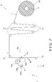
- Figure 9 is a flowchart of printing mode switching control performed before operation of the film supply unit 4.
- step S1 the control unit 7 confirms advance input information.
- the advance input information is information that an operator inputs via the operation switch 5 and the liquid crystal display 6 prior to starting operation of the bag-making and packaging apparatus 1.
- step S2 the control unit 7 determines whether necessary information for selecting the printing mode has been inputted in the advance input information.
- the necessary information in this case is a printing position, a bag length, and the operating mode.
- step S3 when the control unit 7 determines that the necessary information has been inputted.
- the process proceeds to step S2a, and an "input request" indicating that the necessary information is not included in the advance input information is displayed in the liquid crystal display 6 to prompt input of the necessary information.
- step S3 the control unit 7 determines a printing timing.
- the printing timing determines whether printing is performed while the film F is being conveyed, or printing is performed while the film F is stopped.
- control unit 7 determines to perform printing while the film F is being conveyed.
- control unit 7 When the control unit 7 recognizes from the necessary information acquired in step S2 that the operating mode is an intermittent conveyance mode, the control unit 7 determines the printing timing on the basis of the printing position. Printing is generally performed while the film F is stopped when the operating mode is the intermittent conveyance mode.
- step S4 the control unit 7 determines whether the printing timing is to be during conveyance of the film F or during stopping of the film F, the process proceeds to step S5 when it is determined that the printing timing is to be during conveyance of the film F, and the process proceeds to step S6 when it is determined that the printing timing is to be during stopping of the film F.
- the control unit 7 switches the printing mode to the first printing mode in step S5. Specifically, the control unit 7 causes the switching motor 123m of the switching part 123b to rotate, and places the switching part 123b in a first printing state in which the platen roller 123c and the print head 123a face each other with the film F disposed therebetween, as illustrated in FIG. 6 .
- the control unit 7 determines that the printing timing is to be during stopping of the film F, the control unit 7 switches the printing mode to the second printing mode in step S6. Specifically, the control unit 7 causes the switching motor 123m of the switching part 123b to rotate, and places the switching part 123b in a second printing state in which the platen plate 123d and the print head 123a face each other with the film F disposed therebetween, as illustrated in FIG. 7 .
- the printing mode is automatically switched in advance on the basis of the printing timing as described above, erroneous selection of the printing mode is prevented.
- the film supply unit 4 reels out and conveys the film F from the film roll FR fixed to the air shaft 21, and supplies the film F to the shaping mechanism 13 of the bag-making and packaging unit 3. First, the film supply unit 4 conveys the film F reeled out from the film roll FR while guiding the film F in the tension rollers 22.
- the film F is guided in the direction of the printing device 123 by the first feed roller 25 in the film supply unit 4.
- the printing information is then printed in the printing region of the film F by the printing device 123 in the film supply unit 4.
- the film F is then guided in the direction of the inspection device 24 by the second feed roller 26 in the film supply unit 4.
- the film supply unit 4 inspects whether the printing information in the printing region of the film F is correctly printed.
- the film supply unit 4 then sends the film F to the shaping mechanism 13 of the bag-making and packaging unit 3.
- the film F is conveyed and the print head 123a does not move along the conveyance direction of the film F.
- the print head 123a moves relative to the film F in the conveyance direction of the film F, and the printing information is thereby printed in the printing region of the film F.
- the printing mode is switched to the first printing mode.
- the control unit 7 determines on the basis of the advance input information that the timing of printing on the film F is during stoppage of the film F, the printing mode is switched to the second printing mode.
- the printing mode is decided according to the timing of printing on the packaging material regardless of whether bags are manufactured continuously or intermittently, there is no need for the operator to be conscious of which printing mode to operate in, and the printing mode that is suited for production is selected, thereby preventing misoperation.
- the advance input information includes the printing position on the film F and the bag length.
- the printing position on the film F and the bag length are items of information that are inputted to the bag-making and packaging apparatus 1 prior to production and are unlikely to not be inputted, and the information necessary for switching the printing mode is reliably obtained.
- the control unit 7 has the continuous conveyance mode and the intermittent conveyance mode as conveyance modes that can be selected for conveying the film F.
- the continuous conveyance mode is a mode in which the film F is continuously conveyed.
- the intermittent conveyance mode is a mode in which the film F is intermittently conveyed.
- a conveyance mode selection result is also included in the advance input information.
- control unit 7 determines that the conveyance mode is the intermittent conveyance mode, and that the timing of printing on the film F is during conveyance of the film F, the control unit 7 switches the printing mode to the first printing mode. Because the printing mode is switched according to whether the printing timing is during conveyance or during stopping of the film F, even in the intermittent conveyance mode, the printing mode that is suited for production is selected.
- a bag-making and packaging apparatus 1 according to a fourth embodiment of the present invention will be described, focusing on the differences between the fourth embodiment and the bag-making and packaging apparatus 1 according to the third embodiment.
- the bag-making and packaging apparatus 1 of the fourth embodiment comprises a printing device 223.
- the constituent elements other than the printing device 223 are the same as in the third embodiment.
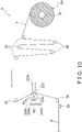
- Figure 10 is a simplified side view of the film supply unit 4 when the printing device 223 of the bag-making and packaging apparatus 1 according to the fourth embodiment is operating in the first printing mode.
- Figure 11 is a simplified side view of the film supply unit 4 when the printing device 223 of the bag-making and packaging apparatus 1 according to the fourth embodiment is operating in the second printing mode.
- the printing device 223 comprises mainly a print head 223a and a switching part 223b.
- the print head 223a prints predetermined printing information on the surface of the film F.
- the printing information is printed in a predetermined printing region on the surface of the film F.
- the printing information is a manufacturing date and an expiration date of the package contents C.
- the printing information is transmitted from the control unit 7 to the printing device 223.
- the print head 223a can move along the direction toward the film F or away from the film F during printing of the printing information.
- a platen roller 223c and a platen plate 223d are retained on respective end parts of the switching part 223b.
- the switching part 223b changes the positions at which the platen roller 223c and the platen plate 223d are retained, in accordance with the operating mode of the bag-making and packaging apparatus 1.
- the platen roller 223c is retained in a position facing the print head 223a, and the platen plate 223d is retained in a position that is separated from the print head 223a.
- the platen plate 223d is retained in a position facing the print head 223a, and the platen roller 223c is retained in a position that is separated from the print head 223a.
- a switching motor 223m can cause the switching part 223b to rotate. Specifically, a rotating shaft of the switching motor 223m is connected to the point P2, and the switching part 223b rotates about the point P2 in accordance with an amount of rotation of the rotating shaft.
- the rotating shaft of the switching motor 223m rotates by a second angle in the direction of the arrow R1, and the switching part 223b thereby rotates in the direction of the arrow R1 and changes to the second printing state (second printing mode) in FIG. 11 .
- the rotating shaft of the switching motor 223m rotates by the second angle in the direction of the arrow R2, and the switching part 223b thereby rotates in the direction of the arrow R2 and changes to the first printing state (first printing mode) in FIG. 10 .
- a servo motor is employed as the switching motor 223m in the present embodiment, but the switching motor 223m is not limited to a servo motor, and another motor, e.g., a stepping motor, may be employed.
- An operator of the bag-making and packaging apparatus 1 can exchange the positions at which the platen roller 223c and the platen plate 223d are retained, without touching the platen roller 223c and the platen plate 223d.
- a bag-making and packaging apparatus 1 according to a fifth embodiment of the present invention will be described, focusing on the differences between the fifth embodiment and the bag-making and packaging apparatus 1 according to the third embodiment.
- the bag-making and packaging apparatus 1 of the fifth embodiment comprises a printing device 323.
- the constituent elements other than the printing device 323 are the same as in the third embodiment.
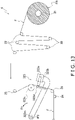
- Figure 12 is a simplified side view of the film supply unit 4 when the printing device 323 of the bag-making and packaging apparatus 1 according to the fifth embodiment is operating in the first printing mode.
- Figure 13 is a simplified side view of the film supply unit 4 when the printing device 323 of the bag-making and packaging apparatus 1 according to the fifth embodiment is operating in the second printing mode.
- the printing device 323 comprises mainly a print head 323a and a switching part 323b.
- the print head 323a prints predetermined printing information on the surface of the film F.
- the printing information is printed in a predetermined printing region on the surface of the film F.
- the printing information is a manufacturing date and an expiration date of the package contents C.
- the printing information is transmitted from the control unit 7 to the printing device 223.
- the print head 323a can move along the direction toward the film F or away from the film F during printing of the printing information.
- the switching part 323b switched between the first printing state and the second printing state by rotating the platen roller 323c and the platen plate 323d.
- the print head 323a switches between the first printing state and the second printing state by moving.
- the positions of the platen roller 323c and the platen plate 323d are fixed.
- the print head 323a can move between the position of the print head 323a in the first printing mode illustrated in FIG. 12 and the position of the print head 323a in the second printing mode illustrated in FIG. 13 .
- a switching motor 323m can cause the print head 323a to move. Specifically, a rotating shaft of the switching motor 323m is connected to the point P3, and the print head 323a rotates about the point P3 in accordance with an amount of rotation of the rotating shaft.
- the rotating shaft of the switching motor 323m rotates by a third angle in the direction of the arrow R2, and the print head 323a thereby rotates in the direction of the arrow R2 and changes to the second printing state (second printing mode) in FIG. 13 .
- the rotating shaft of the switching motor 323m rotates by the third angle in the direction of the arrow R1, and the print head 323a thereby rotates in the direction of the arrow R1 and changes to the first printing state (first printing mode) in FIG. 12 .
- a servo motor is employed as the switching motor 323m in the present embodiment, but the switching motor 323m is not limited to a servo motor, and another motor, e.g., a stepping motor, may be employed.
- a printing defect is brought about by human error in a case in which the printing state is the second printing state irrespective of an input to switch the printing mode to the first printing mode, or in a case in which the printing state is the first printing state irrespective of an input to switch the printing mode to the second printing mode.
- the platen roller and the platen plate can be moved by the operator instead of by a switching motor.
- a bag-making and packaging apparatus 1 according to a sixth embodiment of the present invention will be described, focusing on the differences between the bag-making and packaging apparatus 1 according to the sixth embodiment and the bag-making and packaging apparatus 1 according to the third embodiment.
- the bag-making and packaging apparatus 1 of the sixth embodiment comprises a printing device 423 and an instruction unit 8 to instruct the control unit 7 to switch the printing mode.
- the present embodiment is the same as the third embodiment.
- Figure 14 is a simplified side view of the film supply unit 4 when the printing device 423 of the bag-making and packaging apparatus 1 according to the sixth embodiment is operating in the first printing mode.
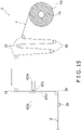
- Figure 15 is a simplified side view of the film supply unit 4 when the printing device 423 of the bag-making and packaging apparatus 1 according to the sixth embodiment is operating in the second printing mode.
- the printing device 423 comprises mainly a print head 423a and a switching part 423b.
- the print head 423a prints predetermined printing information on the surface of the film F.
- the printing information is printed in a predetermined printing region on the surface of the film F.
- the printing information is a manufacturing date and an expiration date of the package contents C.
- the printing information is transmitted from the control unit to the printing device 423.
- the print head 23a can move along the direction toward the film F or away from the film F during printing of the printing information.
- the switching part 423b retains a platen roller 423c or a platen plate 423d. In FIG. 14 , the switching part 423b can retain the platen roller 423c. In FIG. 15 , the switching part 423b can retain the platen plate 423d.
- the platen roller 423c and the platen plate 423d are members for receiving the film F.
- the print head 423a prints the printing information on the surface of the film F
- the print head 423a presses the film F toward the platen roller 423c or the platen plate 423d.
- the platen roller 423c and the platen plate 423d are formed from rubber or another elastic member, for example.
- the platen roller 423c is used in the first printing mode, and the platen plate 423d is used in the second printing mode.
- the platen roller 423c or the platen plate 423d retained by the switching part 423b is arranged facing the print head 423a at a position in which the film F is disposed between the platen roller 423c or the platen plate 423d and the print head 423a.
- the film F reeled out from the film roll FR and conveyed passes between the print head 423a and the platen roller 423c or the platen plate 423d, and is sent to the bag-making and packaging unit 3. While the print head 423a is pressing the film F toward the platen roller 423c or the platen plate 423d, the film F is disposed between the print head 423a and the platen roller 423c or the platen plate 423d.
- the switching part 423b retains the platen roller 423c so that the platen roller 423c and the print head 423a face each other in the first printing mode. In the second printing mode, the switching part 423b retains the platen plate 423d so that the platen plate 423d and the print head 423a face each other.
- the instruction unit 8 specifies the printing mode.
- the instruction unit 8 may be a switch to select the printing mode.
- the instruction unit 8 may be embodied by selection via the liquid crystal display.
- control unit 7 determines on the basis of the advance input information and an instruction from the instruction unit 8 that the timing of printing on the film F is during conveyance of the film F, the control unit 7 issues an instruction via the liquid crystal display 6 to switch the printing mode to the first printing mode.
- control unit 7 determines that the timing of printing on the film F is during stoppage of the film F, the control unit 7 issues an instruction via the liquid crystal display to switch the printing mode to the second printing mode.
- the operator switches the printing mode to the mode that is displayed in the liquid crystal display 6, i.e., to the first printing mode or the second printing mode.
- control unit 7 issues a warning via the liquid crystal display 6 to prompt review of the printing mode.
- the operator exchanges the platen roller 423c or the platen plate 423d retained by the switching part 423b, in accordance with the printing mode displayed in the liquid crystal display 6.
- the operator of the bag-making and packaging apparatus 1 removes the platen plate 423d from the switching part 423b and attaches the platen roller 423c to the switching part 423b, placing the switching part 423b in the first printing state.
- the operator of the bag-making and packaging apparatus 1 removes the platen roller 423c from the switching part 423b and attaches the platen plate 423d to the switching part 423b, placing the switching part 423b in the second printing state.
- control unit 7 is configured so that a first signal is inputted to the control unit 7 when the printing state is the first printing state, and a second signal is inputted to the control unit 7 when the printing state is the second printing state.
- the film supply unit 4 reels out and conveys the film F from the film roll FR fixed to the air shaft 21, and supplies the film F to the shaping mechanism 13 of the bag-making and packaging unit 3. First, the film supply unit 4 conveys the film F reeled out from the film roll FR while guiding the film F with the tension rollers 22.
- the film F is guided in the direction of the printing device 423 by the first feed roller 25 in the film supply unit 4.
- the printing information is then printed in the printing region of the film F by the printing device 423 in the film supply unit 4.
- the film F is then guided in the direction of the inspection device 24 by the second feed roller 26 in the film supply unit 4.
- the film supply unit 4 inspects whether the printing information in the printing region of the film F is correctly printed.
- the film supply unit 4 then sends the film F to the shaping mechanism 13 of the bag-making and packaging unit 3.
- the film F is conveyed and the print head 423a does not move along the conveyance direction of the film F.
- the print head 423a moves relative to the film F in the conveyance direction of the film F, and the printing information is thereby printed in the printing region of the film F.
- a bag-making and packaging apparatus 1 according to a seventh embodiment of the present invention will be described, focusing on the differences between the bag-making and packaging apparatus 1 according to the seventh embodiment and the bag-making and packaging apparatus 1 according to the sixth embodiment.
- the bag-making and packaging apparatus 1 of the seventh embodiment comprises a printing device 523.
- the constituent elements other than the printing device 523 are the same as in the third embodiment.
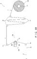
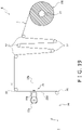
- Figure 16 is a simplified side view of the film supply unit 4 when the printing device 523 of the bag-making and packaging apparatus 1 according to the seventh embodiment is operating in the first printing mode.
- Figure 17 is a simplified side view of the film supply unit 4 when the printing device 523 of the bag-making and packaging apparatus 1 according to the seventh embodiment is operating in the second printing mode.
- the printing device 523 comprises mainly a print head 523a and a switching part 523b.
- the print head 523a prints predetermined printing information on the surface of the film F.
- the printing information is printed in a predetermined printing region on the surface of the film F.
- the printing information is a manufacturing date and an expiration date of the package contents C.
- the printing information is transmitted from the control unit to the printing device 423.
- the print head 523a can move along the direction toward the film F or away from the film F during printing of the printing information.
- the switching part 523b illustrated in FIGS. 16 and 17 retains both a platen roller 523c and a platen plate 523d in advance.
- a portion in which the platen roller 523c is retained and a portion in which the platen plate 523d is retained are not linked, and are independent from each other.
- the operator of the bag-making and packaging apparatus 1 can move the platen roller 523c and the platen plate 523d separately by moving only a portion of the switching part 523b.
- the portion in which the platen roller 523c is retained and the portion in which the platen plate 523d is retained can be moved independently of each other. Furthermore, the switching part 523b can cause the platen roller 523c and the platen plate 523d to move along the film F.
- the operator moves the platen roller 523c away from the print head 523a, and brings the platen plate 523d close to the print head 523a.
- the operator moves the platen plate 523d away from the print head 523a, and brings the platen roller 523c close to the print head 523a.
- the operator can switch between the first printing state and the second printing state by moving the switching part 523b.
- the operator can also easily position the platens 523c, 523d in accordance with the printing mode without detaching the platens 523c, 523d from the film supply unit 4.
- the retaining part 23b retains either a platen roller 23c or a platen plate 23d.
- the retaining part 23b may retain both a platen roller 23c and a platen plate 23d.
- Figures 18 and 19 are side views showing a simplified configuration of the film supply unit 4 of the present modification, in the same manner as FIGS. 4 and 5 .
- Figure 18 illustrates a configuration in the continuous mode.
- Figure 19 illustrates a configuration in the intermittent mode.
- a platen roller 23c and a platen plate 23d are retained on respective end parts of the retaining part 23b.
- the retaining part 23b is configured so that the positions at which the platen roller 23c and the platen plate 23d are retained can be changed in accordance with the operating mode of the bag-making and packaging apparatus 1.
- the platen roller 23c is retained in a position facing the print head 23a, and the platen plate 23d is retained in a position that is separated from the print head 23a.
- the platen plate 23d is retained in a position facing the print head 23a, and the platen roller 23c is retained in a position that is separated from the print head 23a.
- the operator of the bag-making and packaging apparatus 1 When switching the operating mode, the operator of the bag-making and packaging apparatus 1 removes the platen roller 23c and the platen plate 23d from the retaining part 23b. Before and after switching the operating mode, the operator attaches the platen roller 23c and the platen plate 23d to the retaining part 23b so that the positions in which the platen roller 23c and the platen plate 23d are retained are exchanged.
- the retaining part 23b may be fixed to the film supply unit 4, and may be configured so as to be attachable to and detachable from the film supply unit 4.
- the operator of the bag-making and packaging apparatus 1 need only change the orientation of the retaining part 23b when switching the operating mode. In this case, the operator of the bag-making and packaging apparatus 1 can exchange the positions at which the platen roller 23c and the platen plate 23d are retained, without touching the platen roller 23c and the platen plate 23d.
- the switching part 123b is configured so that at least one of the platen roller 123c and the platen plate 123d are moved to switch between the first printing state and the second printing state.
- the switching part 123b may be configured so that the first printing state and the second printing state are switched by moving the print head 123a instead of by moving the platen roller 123c and the platen plate 123d.
- a specific example of the configuration of the switching part 123b will next be described.
- Figures 20 and 21 are side views showing a simplified configuration of the film supply unit 4 of the present modification, in the same manner as FIGS. 4 and 5 .
- Figure 20 illustrates a configuration in the continuous mode.
- Figure 21 illustrates a configuration in the intermittent mode.
- the switching part 123b is a member in which the print head 123a is retained, as illustrated in FIGS. 20 and 21 .
- the positions of the platen roller 123c and the platen plate 123d are fixed.
- the switching part 123b is configured so as to be able to move between the position of the print head 123a in the first printing state illustrated in FIG. 20 and the position of the print head 123a in the second printing state illustrated in FIG. 21 .
- the operator of the bag-making and packaging apparatus 1 can switch between the first printing state and the second printing state by moving the switching part 123b to cause the print head 123a to move along the film F.
- the switching part 123b is configured so that at least one of the platen roller 123c and the platen plate 123d are moved to switch between the first printing state and the second printing state.
- the switching part 123b may be configured so that the first printing state and the second printing state are switched by further moving the feed rollers 25, 26.
- the operator of the bag-making and packaging apparatus 1 can switch between the first printing state and the second printing state by operating the switching part 123b.
- the operator of the bag-making and packaging apparatus 1 can switch between the first printing state and the second printing state by manually moving the switching part 123b.
- the switching part 123b may also be configured so as to be movable by an air cylinder or other drive mechanism.
- the bag-making and packaging apparatus 1 may be configured so that it is possible to switch between the first printing state and the second printing state without manually moving the switching part 123b.
- the bag-making and packaging apparatus 1 may be configured so that the operator can switch between the first printing state and the second printing state by operating the operation switch 5 or the liquid crystal display 6.
- the operation switch 5 may include a switch to switch the operating mode of the bag-making and packaging apparatus 1
- the liquid crystal display 6 may be a touch panel to display a screen image for switching the operating mode of the bag-making and packaging apparatus 1, for example.
- the bag-making and packaging apparatus 1 uses two types of platens, i.e., a platen roller 23c, 123c and a platen plate 23d, 123d.
- the present invention is also applicable to a bag-making and packaging apparatus 1 that uses three or more types of platens.
- Patent Literature 1 Japanese Patent Unexamined Publication JP 2012-136270 A
Claims (11)
- Beutelherstellungs- und Verpackungsvorrichtung (1), in der ein Beutel (B), in dem ein Artikel verpackt wird, aus einem Verpackungsmaterial (F) gebildet wird, während das Verpackungsmaterial befördert wird, wobei die Beutelherstellungs- und Verpackungsvorrichtung (1) aufweist:einen Druckteil (23a), um vorbestimmte Informationen auf das Verpackungsmaterial zu drucken, bevor der Beutel gebildet wird;dadurch gekennzeichnet, dass die Beutelherstellungs- und Verpackungsvorrichtung (1) ferner aufweist:einen ersten Aufnahmeteil (23c), der in einem ersten Druckmodus verwendet wird, um auf das Verpackungsmaterials während dessen Transports zu drucken, ohne die Beförderung des Verpackungsmaterials anzuhalten;einen zweiten Aufnahmeteil (23d), der in einem zweiten Druckmodus verwendet wird, um auf das angehaltene Verpackungsmaterial zu einem Zeitpunkt zu drucken, zu dem die Beförderung des Verpackungsmaterials angehalten wird; undeinen Halteteil (23b), um mindestens eines des ersten Aufnahmeteils (23c) und des zweiten Aufnahmeteils (23d) zu halten,wobei der Halteteil (23b) mindestens einen des ersten Aufnahmeteils (23a) und des zweiten Aufnahmeteils (23d) hält, so dass der erste Aufnahmeteil (23c) und der Druckteil (23a) einander gegenüberliegen, wobei das Verpackungsmaterial im ersten Druckmodus dazwischen angeordnet ist, und der zweite Aufnahmeteil (23d) und der Druckteil (23a) einander gegenüberliegen, wobei das Verpackungsmaterial im zweiten Druckmodus dazwischen angeordnet ist.
- Beutelherstellungs- und Verpackungsvorrichtung (1), in der ein Beutel (B), in dem ein Artikel verpackt wird, aus einem Verpackungsmaterial (F) gebildet wird, während das Verpackungsmaterial gefördert wird, wobei die Beutelherstellungs- und Verpackungsvorrichtung (1) aufweist:einen Druckteil (123a), um vorbestimmte Informationen auf das Verpackungsmaterial zu drucken, bevor der Beutel gebildet wird;dadurch gekennzeichnet, dass die Beutelherstellungs- und Verpackungsvorrichtung (1) ferner aufweist:einen ersten Aufnahmeteil (123c), der zum Bedrucken des Verpackungsmaterials während seiner Beförderung verwendet wird, ohne die Beförderung des Verpackungsmaterials anzuhalten;einen zweiten Aufnahmeteil (123d), der zum Bedrucken des angehaltenen Verpackungsmaterials zu einem Zeitpunkt verwendet wird, zu dem die Beförderung des Verpackungsmaterials angehalten ist; undeinen Umschaltteil (123b) zum Umschalten zwischen einem ersten Druckzustand, in dem der erste Aufnahmeteil (123c) und der Druckteil (123a) einander gegenüberliegen, wobei das Verpackungsmaterial dazwischen angeordnet ist, und einem zweiten Druckzustand, in dem der zweite Aufnahmeteil (123d) und der Druckteil (123a) einander gegenüberliegen, wobei das Verpackungsmaterial dazwischen angeordnet ist.
- Beutelherstellungs- und Verpackungsvorrichtung (1) nach Anspruch 2, wobei
der Umschaltteil (123b) zwischen dem ersten Druckzustand und dem zweiten Druckzustand umschaltet, indem er bewirkt, dass sich mindestens einer des ersten Aufnahmeteils (123c) und des zweiten Aufnahmeteils (123d) bewegt. - Beutelherstellungs- und Verpackungsvorrichtung (1) nach Anspruch 2, wobei
der Umschaltteil (123b) zwischen dem ersten Druckzustand und dem zweiten Druckzustand umschaltet, indem er bewirkt, dass sich der Druckteil (123a) bewegt. - Beutelherstellungs- und Verpackungsvorrichtung (1) nach Anspruch 4, wobei
der Umschaltteil (123b) den Druckteil (123a) veranlasst, sich entlang des Verpackungsmaterials zu bewegen. - Beutelherstellungs- und Verpackungsvorrichtung nach einem der Ansprüche 2 bis 5, die ferner aufweisteine Förderrolle (25) zum Senden des Verpackungsmaterials zwischen dem ersten Aufnahmeteil (123c) und dem Druckteil (123a) oder zwischen dem zweiten Aufnahmeteil (123d) und dem Druckteil (123a),wobei der Umschaltteil (123b) zwischen dem ersten Druckzustand und dem zweiten Druckzustand umschaltet, indem er bewirkt, dass sich er die Förderrolle (25) bewegt.
- Beutelherstellungs- und Verpackungsvorrichtung (1) nach einem der Ansprüche 1 bis 5, wobeider erste Aufnahmeteil (23c, 123c) ein zylindrisches Element ist, undder zweite Aufnahmeteil (23d, 123d) ein flaches, plattenförmiges Element ist.
- Beutelherstellungs- und Verpackungsvorrichtung (1) nach Anspruch 1 oder 2, die ferner aufweist:eine Steuereinheit (7) zum Steuern des Betriebs des Druckteils (23a, 123a) auf der Grundlage von vorbestimmten Informationen, die im Voraus eingegeben werden,wobei der Druckteil (23a, 123a) den ersten Druckmodus und den zweiten Druckmodus als auswählbare Druckmodi zum Bedrucken des Verpackungsmaterials aufweist,die Steuereinheit (7) auf der Grundlage der vorbestimmten Informationen den Druckmodus auf den ersten Druckmodus umschaltet, wenn festgestellt wird, dass der Zeitpunkt des Bedruckens des Verpackungsmaterials während der Beförderung des Verpackungsmaterials liegt, unddie Steuereinheit (7) auf der Grundlage der vorbestimmten Informationen den Druckmodus in den zweiten Druckmodus umschaltet, wenn festgestellt wird, dass der Zeitpunkt des Bedruckens des Verpackungsmaterials während des Anhaltens des Verpackungsmaterials liegt.
- Beutelherstellungs- und Verpackungsvorrichtung (1) nach Anspruch 1 oder 2, die ferner aufweist:eine Steuereinheit (7) zum Steuern des Betriebs des Druckteils; undeine Anweisungseinheit (8),wobei der Druckteil (23a, 123a) den ersten Druckmodus und den zweiten Druckmodus als eine Vielzahl von auswählbaren Druckmodi zum Bedrucken des Verpackungsmaterials aufweist, die Anweisungseinheit (8) die Steuereinheit anweist, den Druckmodus zu wechseln,die Steuereinheit (7) auf der Grundlage von vorbestimmten Informationen, die im Voraus eingegeben werden, und einer Anweisung von der Anweisungseinheit (8) anweist, den Druckmodus auf den ersten Druckmodus umzuschalten, wenn festgestellt wird, dass der Zeitpunkt des Druckens auf das Verpackungsmaterial während der Beförderung des Verpackungsmaterials ist, unddie Steuereinheit (7) auf der Grundlage von vorbestimmten Informationen, die im Voraus eingegeben werden, und einer Anweisung von der Anweisungseinheit (8) anweist, den Druckmodus in den zweiten Druckmodus umzuschalten, wenn festgestellt wird, dass der Zeitpunkt des Bedruckens des Verpackungsmaterials während des Anhaltens des Verpackungsmaterials liegt.
- Beutelherstellungs- und Verpackungsvorrichtung (1) nach Anspruch 8 oder 9, wobei
die Steuereinheit (7) als wählbare Fördermodi zum Fördern des Verpackungsmaterials aufweist:
einen ersten Fördermodus zum kontinuierlichen Fördern des Verpackungsmaterials und einen zweiten Fördermodus zum intermittierenden Fördern des Verpackungsmaterials, wobei die vorbestimmten Informationen ein Ergebnis der Auswahl des Fördermodus enthalten. - Beutelherstellungs- und Verpackungsvorrichtung (1) nach Anspruch 10, wobei
die Steuereinheit (7) den Druckmodus auf den ersten Druckmodus umschaltet, wenn der Fördermodus der zweite Fördermodus ist und festgestellt wird, dass der Zeitpunkt des Bedruckens des Verpackungsmaterials während des Transports des Verpackungsmaterials liegt.
Applications Claiming Priority (2)
| Application Number | Priority Date | Filing Date | Title |
|---|---|---|---|
| JP2020051674A JP2021147098A (ja) | 2020-03-23 | 2020-03-23 | 製袋包装機 |
| JP2020051673A JP7450250B2 (ja) | 2020-03-23 | 2020-03-23 | 製袋包装機 |
Publications (2)
| Publication Number | Publication Date |
|---|---|
| EP3885276A1 EP3885276A1 (de) | 2021-09-29 |
| EP3885276B1 true EP3885276B1 (de) | 2023-01-18 |
Family
ID=75143504
Family Applications (1)
| Application Number | Title | Priority Date | Filing Date |
|---|---|---|---|
| EP21163931.5A Active EP3885276B1 (de) | 2020-03-23 | 2021-03-22 | Beutelherstellungs- und -verpackungsvorrichtung |
Country Status (2)
| Country | Link |
|---|---|
| US (1) | US20210292026A1 (de) |
| EP (1) | EP3885276B1 (de) |
Citations (3)
| Publication number | Priority date | Publication date | Assignee | Title |
|---|---|---|---|---|
| EP0999141A2 (de) | 1998-11-03 | 2000-05-10 | Klockner Bartelt, Inc. | Servogesteuerte Vorrichtung zum Herstellen von Beuteln |
| WO2002022371A2 (en) | 2000-09-11 | 2002-03-21 | Zipher Limited | Tape drive and printing apparatus |
| EP3246262A1 (de) | 2015-01-15 | 2017-11-22 | Ishida Co., Ltd. | Beutelherstellung und verpackungsmaschine |
Family Cites Families (4)
| Publication number | Priority date | Publication date | Assignee | Title |
|---|---|---|---|---|
| US2308563A (en) * | 1939-05-16 | 1943-01-19 | Western Union Telegraph Co | Printing mechanism |
| JP2000214567A (ja) * | 1998-11-17 | 2000-08-04 | Seiko Instruments Inc | 感光型マイクロカプセルを塗布したプリント用紙を用いるプリンタ及びこれを用いたプリントシステム |
| JP5628660B2 (ja) | 2010-12-27 | 2014-11-19 | 株式会社イシダ | 製袋包装機 |
| US9242776B2 (en) * | 2012-04-20 | 2016-01-26 | Shane Mikula | Glue application method for cold seal cohesive packaging |
-
2021
- 2021-03-22 EP EP21163931.5A patent/EP3885276B1/de active Active
- 2021-03-23 US US17/209,225 patent/US20210292026A1/en not_active Abandoned
Patent Citations (3)
| Publication number | Priority date | Publication date | Assignee | Title |
|---|---|---|---|---|
| EP0999141A2 (de) | 1998-11-03 | 2000-05-10 | Klockner Bartelt, Inc. | Servogesteuerte Vorrichtung zum Herstellen von Beuteln |
| WO2002022371A2 (en) | 2000-09-11 | 2002-03-21 | Zipher Limited | Tape drive and printing apparatus |
| EP3246262A1 (de) | 2015-01-15 | 2017-11-22 | Ishida Co., Ltd. | Beutelherstellung und verpackungsmaschine |
Non-Patent Citations (1)
| Title |
|---|
| ANONYMOUS: "Quorn", WIKIPEDIA, THE FREE ENCYCLOPEDIA, 4 October 2023 (2023-10-04), XP093144465, Retrieved from the Internet <URL:https://en.wikipedia.org/wiki/Quorn> [retrieved on 20240322] |
Also Published As
| Publication number | Publication date |
|---|---|
| US20210292026A1 (en) | 2021-09-23 |
| EP3885276A1 (de) | 2021-09-29 |
Similar Documents
| Publication | Publication Date | Title |
|---|---|---|
| JP2008127093A (ja) | フィルム供給装置およびこれを備えた包装装置 | |
| NL1016524C2 (nl) | Vorm-, vul- en sluitmachine. | |
| WO2016113962A1 (ja) | 製袋包装機 | |
| EP2495177B1 (de) | Beutelpackautomat | |
| WO2019035265A1 (ja) | 商品処理装置 | |
| JP6847802B2 (ja) | 位置算出システム、製袋可能数算出システム、位置算出方法、製袋可能数算出方法および包装機 | |
| JP2024023791A (ja) | 製袋包装機 | |
| WO2019026316A1 (ja) | ブリスター包装機 | |
| JP7224643B2 (ja) | 製袋包装機 | |
| JP2005075401A (ja) | 包装装置 | |
| CN107531351B (zh) | 生产线构成装置 | |
| EP3885276B1 (de) | Beutelherstellungs- und -verpackungsvorrichtung | |
| CN108860789B (zh) | 泡罩包装机 | |
| JP6902274B2 (ja) | 製袋包装機 | |
| JP2021147098A (ja) | 製袋包装機 | |
| JP6877040B2 (ja) | 製袋包装機 | |
| JP2009280259A (ja) | 製袋包装機 | |
| JP2009161228A (ja) | 製袋包装機 | |
| JP2008127092A (ja) | フィルム供給装置およびこれを備えた包装装置 | |
| JP3830437B2 (ja) | 製袋包装機 | |
| EP4286286A1 (de) | Verpackungsvorrichtung | |
| WO2022014006A1 (ja) | 製袋包装機 | |
| JP2022012869A (ja) | 製袋包装機 | |
| NL1020510C2 (nl) | Vorm-, vul- en sluitmachine met baankantvolger. | |
| JP2012197101A (ja) | 製袋包装機 |
Legal Events
| Date | Code | Title | Description |
|---|---|---|---|
| PUAI | Public reference made under article 153(3) epc to a published international application that has entered the european phase |
Free format text: ORIGINAL CODE: 0009012 |
|
| STAA | Information on the status of an ep patent application or granted ep patent |
Free format text: STATUS: THE APPLICATION HAS BEEN PUBLISHED |
|
| AK | Designated contracting states |
Kind code of ref document: A1 Designated state(s): AL AT BE BG CH CY CZ DE DK EE ES FI FR GB GR HR HU IE IS IT LI LT LU LV MC MK MT NL NO PL PT RO RS SE SI SK SM TR |
|
| STAA | Information on the status of an ep patent application or granted ep patent |
Free format text: STATUS: REQUEST FOR EXAMINATION WAS MADE |
|
| 17P | Request for examination filed |
Effective date: 20211220 |
|
| RBV | Designated contracting states (corrected) |
Designated state(s): AL AT BE BG CH CY CZ DE DK EE ES FI FR GB GR HR HU IE IS IT LI LT LU LV MC MK MT NL NO PL PT RO RS SE SI SK SM TR |
|
| STAA | Information on the status of an ep patent application or granted ep patent |
Free format text: STATUS: EXAMINATION IS IN PROGRESS |
|
| 17Q | First examination report despatched |
Effective date: 20220215 |
|
| GRAP | Despatch of communication of intention to grant a patent |
Free format text: ORIGINAL CODE: EPIDOSNIGR1 |
|
| STAA | Information on the status of an ep patent application or granted ep patent |
Free format text: STATUS: GRANT OF PATENT IS INTENDED |
|
| INTG | Intention to grant announced |
Effective date: 20220812 |
|
| GRAS | Grant fee paid |
Free format text: ORIGINAL CODE: EPIDOSNIGR3 |
|
| GRAA | (expected) grant |
Free format text: ORIGINAL CODE: 0009210 |
|
| STAA | Information on the status of an ep patent application or granted ep patent |
Free format text: STATUS: THE PATENT HAS BEEN GRANTED |
|
| AK | Designated contracting states |
Kind code of ref document: B1 Designated state(s): AL AT BE BG CH CY CZ DE DK EE ES FI FR GB GR HR HU IE IS IT LI LT LU LV MC MK MT NL NO PL PT RO RS SE SI SK SM TR |
|
| REG | Reference to a national code |
Ref country code: GB Ref legal event code: FG4D |
|
| REG | Reference to a national code |
Ref country code: CH Ref legal event code: EP |
|
| REG | Reference to a national code |
Ref country code: DE Ref legal event code: R096 Ref document number: 602021001241 Country of ref document: DE |
|
| REG | Reference to a national code |
Ref country code: AT Ref legal event code: REF Ref document number: 1544570 Country of ref document: AT Kind code of ref document: T Effective date: 20230215 Ref country code: IE Ref legal event code: FG4D |
|
| REG | Reference to a national code |
Ref country code: NL Ref legal event code: FP |
|
| REG | Reference to a national code |
Ref country code: LT Ref legal event code: MG9D |
|
| PGFP | Annual fee paid to national office [announced via postgrant information from national office to epo] |
Ref country code: DE Payment date: 20230321 Year of fee payment: 3 |
|
| REG | Reference to a national code |
Ref country code: AT Ref legal event code: MK05 Ref document number: 1544570 Country of ref document: AT Kind code of ref document: T Effective date: 20230118 |
|
| PG25 | Lapsed in a contracting state [announced via postgrant information from national office to epo] |
Ref country code: RS Free format text: LAPSE BECAUSE OF FAILURE TO SUBMIT A TRANSLATION OF THE DESCRIPTION OR TO PAY THE FEE WITHIN THE PRESCRIBED TIME-LIMIT Effective date: 20230118 Ref country code: PT Free format text: LAPSE BECAUSE OF FAILURE TO SUBMIT A TRANSLATION OF THE DESCRIPTION OR TO PAY THE FEE WITHIN THE PRESCRIBED TIME-LIMIT Effective date: 20230518 Ref country code: NO Free format text: LAPSE BECAUSE OF FAILURE TO SUBMIT A TRANSLATION OF THE DESCRIPTION OR TO PAY THE FEE WITHIN THE PRESCRIBED TIME-LIMIT Effective date: 20230418 Ref country code: LV Free format text: LAPSE BECAUSE OF FAILURE TO SUBMIT A TRANSLATION OF THE DESCRIPTION OR TO PAY THE FEE WITHIN THE PRESCRIBED TIME-LIMIT Effective date: 20230118 Ref country code: LT Free format text: LAPSE BECAUSE OF FAILURE TO SUBMIT A TRANSLATION OF THE DESCRIPTION OR TO PAY THE FEE WITHIN THE PRESCRIBED TIME-LIMIT Effective date: 20230118 Ref country code: HR Free format text: LAPSE BECAUSE OF FAILURE TO SUBMIT A TRANSLATION OF THE DESCRIPTION OR TO PAY THE FEE WITHIN THE PRESCRIBED TIME-LIMIT Effective date: 20230118 Ref country code: ES Free format text: LAPSE BECAUSE OF FAILURE TO SUBMIT A TRANSLATION OF THE DESCRIPTION OR TO PAY THE FEE WITHIN THE PRESCRIBED TIME-LIMIT Effective date: 20230118 Ref country code: AT Free format text: LAPSE BECAUSE OF FAILURE TO SUBMIT A TRANSLATION OF THE DESCRIPTION OR TO PAY THE FEE WITHIN THE PRESCRIBED TIME-LIMIT Effective date: 20230118 |
|
| PG25 | Lapsed in a contracting state [announced via postgrant information from national office to epo] |
Ref country code: SE Free format text: LAPSE BECAUSE OF FAILURE TO SUBMIT A TRANSLATION OF THE DESCRIPTION OR TO PAY THE FEE WITHIN THE PRESCRIBED TIME-LIMIT Effective date: 20230118 Ref country code: PL Free format text: LAPSE BECAUSE OF FAILURE TO SUBMIT A TRANSLATION OF THE DESCRIPTION OR TO PAY THE FEE WITHIN THE PRESCRIBED TIME-LIMIT Effective date: 20230118 Ref country code: IS Free format text: LAPSE BECAUSE OF FAILURE TO SUBMIT A TRANSLATION OF THE DESCRIPTION OR TO PAY THE FEE WITHIN THE PRESCRIBED TIME-LIMIT Effective date: 20230518 Ref country code: GR Free format text: LAPSE BECAUSE OF FAILURE TO SUBMIT A TRANSLATION OF THE DESCRIPTION OR TO PAY THE FEE WITHIN THE PRESCRIBED TIME-LIMIT Effective date: 20230419 Ref country code: FI Free format text: LAPSE BECAUSE OF FAILURE TO SUBMIT A TRANSLATION OF THE DESCRIPTION OR TO PAY THE FEE WITHIN THE PRESCRIBED TIME-LIMIT Effective date: 20230118 |
|
| REG | Reference to a national code |
Ref country code: DE Ref legal event code: R026 Ref document number: 602021001241 Country of ref document: DE |
|
| PLBI | Opposition filed |
Free format text: ORIGINAL CODE: 0009260 |
|
| PLAB | Opposition data, opponent's data or that of the opponent's representative modified |
Free format text: ORIGINAL CODE: 0009299OPPO |
|
| PG25 | Lapsed in a contracting state [announced via postgrant information from national office to epo] |
Ref country code: SM Free format text: LAPSE BECAUSE OF FAILURE TO SUBMIT A TRANSLATION OF THE DESCRIPTION OR TO PAY THE FEE WITHIN THE PRESCRIBED TIME-LIMIT Effective date: 20230118 Ref country code: RO Free format text: LAPSE BECAUSE OF FAILURE TO SUBMIT A TRANSLATION OF THE DESCRIPTION OR TO PAY THE FEE WITHIN THE PRESCRIBED TIME-LIMIT Effective date: 20230118 Ref country code: MC Free format text: LAPSE BECAUSE OF FAILURE TO SUBMIT A TRANSLATION OF THE DESCRIPTION OR TO PAY THE FEE WITHIN THE PRESCRIBED TIME-LIMIT Effective date: 20230118 Ref country code: EE Free format text: LAPSE BECAUSE OF FAILURE TO SUBMIT A TRANSLATION OF THE DESCRIPTION OR TO PAY THE FEE WITHIN THE PRESCRIBED TIME-LIMIT Effective date: 20230118 Ref country code: DK Free format text: LAPSE BECAUSE OF FAILURE TO SUBMIT A TRANSLATION OF THE DESCRIPTION OR TO PAY THE FEE WITHIN THE PRESCRIBED TIME-LIMIT Effective date: 20230118 Ref country code: CZ Free format text: LAPSE BECAUSE OF FAILURE TO SUBMIT A TRANSLATION OF THE DESCRIPTION OR TO PAY THE FEE WITHIN THE PRESCRIBED TIME-LIMIT Effective date: 20230118 |
|
| PLAX | Notice of opposition and request to file observation + time limit sent |
Free format text: ORIGINAL CODE: EPIDOSNOBS2 |
|
| 26 | Opposition filed |
Opponent name: GEA FOOD SOLUTIONS WEERT B.V. Effective date: 20231018 |
|
| R26 | Opposition filed (corrected) |
Opponent name: GEA FOOD SOLUTIONS WEERT B.V. Effective date: 20231018 |
|
| PG25 | Lapsed in a contracting state [announced via postgrant information from national office to epo] |
Ref country code: SK Free format text: LAPSE BECAUSE OF FAILURE TO SUBMIT A TRANSLATION OF THE DESCRIPTION OR TO PAY THE FEE WITHIN THE PRESCRIBED TIME-LIMIT Effective date: 20230118 |
|
| REG | Reference to a national code |
Ref country code: BE Ref legal event code: MM Effective date: 20230331 |
|
| PG25 | Lapsed in a contracting state [announced via postgrant information from national office to epo] |
Ref country code: LU Free format text: LAPSE BECAUSE OF NON-PAYMENT OF DUE FEES Effective date: 20230322 |
|
| REG | Reference to a national code |
Ref country code: IE Ref legal event code: MM4A |
|
| PG25 | Lapsed in a contracting state [announced via postgrant information from national office to epo] |
Ref country code: SI Free format text: LAPSE BECAUSE OF FAILURE TO SUBMIT A TRANSLATION OF THE DESCRIPTION OR TO PAY THE FEE WITHIN THE PRESCRIBED TIME-LIMIT Effective date: 20230118 Ref country code: IE Free format text: LAPSE BECAUSE OF NON-PAYMENT OF DUE FEES Effective date: 20230322 Ref country code: FR Free format text: LAPSE BECAUSE OF NON-PAYMENT OF DUE FEES Effective date: 20230331 |
|
| PG25 | Lapsed in a contracting state [announced via postgrant information from national office to epo] |
Ref country code: BE Free format text: LAPSE BECAUSE OF NON-PAYMENT OF DUE FEES Effective date: 20230331 |
|
| PLBB | Reply of patent proprietor to notice(s) of opposition received |
Free format text: ORIGINAL CODE: EPIDOSNOBS3 |