EP3882866B1 - Information processing system, information processing method, and program - Google Patents
Information processing system, information processing method, and program Download PDFInfo
- Publication number
- EP3882866B1 EP3882866B1 EP19884420.1A EP19884420A EP3882866B1 EP 3882866 B1 EP3882866 B1 EP 3882866B1 EP 19884420 A EP19884420 A EP 19884420A EP 3882866 B1 EP3882866 B1 EP 3882866B1
- Authority
- EP
- European Patent Office
- Prior art keywords
- virtual viewpoint
- image
- information
- virtual
- image format
- Prior art date
- Legal status (The legal status is an assumption and is not a legal conclusion. Google has not performed a legal analysis and makes no representation as to the accuracy of the status listed.)
- Active
Links
Images


Classifications
-
- G—PHYSICS
- G06—COMPUTING OR CALCULATING; COUNTING
- G06T—IMAGE DATA PROCESSING OR GENERATION, IN GENERAL
- G06T15/00—Three-dimensional [3D] image rendering
- G06T15/10—Geometric effects
- G06T15/20—Perspective computation
- G06T15/205—Image-based rendering
-
- H—ELECTRICITY
- H04—ELECTRIC COMMUNICATION TECHNIQUE
- H04N—PICTORIAL COMMUNICATION, e.g. TELEVISION
- H04N13/00—Stereoscopic video systems; Multi-view video systems; Details thereof
- H04N13/10—Processing, recording or transmission of stereoscopic or multi-view image signals
- H04N13/106—Processing image signals
- H04N13/111—Transformation of image signals corresponding to virtual viewpoints, e.g. spatial image interpolation
- H04N13/117—Transformation of image signals corresponding to virtual viewpoints, e.g. spatial image interpolation the virtual viewpoint locations being selected by the viewers or determined by viewer tracking
-
- G—PHYSICS
- G06—COMPUTING OR CALCULATING; COUNTING
- G06F—ELECTRIC DIGITAL DATA PROCESSING
- G06F3/00—Input arrangements for transferring data to be processed into a form capable of being handled by the computer; Output arrangements for transferring data from processing unit to output unit, e.g. interface arrangements
- G06F3/01—Input arrangements or combined input and output arrangements for interaction between user and computer
- G06F3/048—Interaction techniques based on graphical user interfaces [GUI]
- G06F3/0481—Interaction techniques based on graphical user interfaces [GUI] based on specific properties of the displayed interaction object or a metaphor-based environment, e.g. interaction with desktop elements like windows or icons, or assisted by a cursor's changing behaviour or appearance
-
- G—PHYSICS
- G06—COMPUTING OR CALCULATING; COUNTING
- G06F—ELECTRIC DIGITAL DATA PROCESSING
- G06F3/00—Input arrangements for transferring data to be processed into a form capable of being handled by the computer; Output arrangements for transferring data from processing unit to output unit, e.g. interface arrangements
- G06F3/01—Input arrangements or combined input and output arrangements for interaction between user and computer
- G06F3/048—Interaction techniques based on graphical user interfaces [GUI]
- G06F3/0484—Interaction techniques based on graphical user interfaces [GUI] for the control of specific functions or operations, e.g. selecting or manipulating an object, an image or a displayed text element, setting a parameter value or selecting a range
-
- G—PHYSICS
- G06—COMPUTING OR CALCULATING; COUNTING
- G06F—ELECTRIC DIGITAL DATA PROCESSING
- G06F3/00—Input arrangements for transferring data to be processed into a form capable of being handled by the computer; Output arrangements for transferring data from processing unit to output unit, e.g. interface arrangements
- G06F3/01—Input arrangements or combined input and output arrangements for interaction between user and computer
- G06F3/048—Interaction techniques based on graphical user interfaces [GUI]
- G06F3/0487—Interaction techniques based on graphical user interfaces [GUI] using specific features provided by the input device, e.g. functions controlled by the rotation of a mouse with dual sensing arrangements, or of the nature of the input device, e.g. tap gestures based on pressure sensed by a digitiser
-
- G—PHYSICS
- G06—COMPUTING OR CALCULATING; COUNTING
- G06T—IMAGE DATA PROCESSING OR GENERATION, IN GENERAL
- G06T1/00—General purpose image data processing
- G06T1/20—Processor architectures; Processor configuration, e.g. pipelining
-
- G—PHYSICS
- G06—COMPUTING OR CALCULATING; COUNTING
- G06T—IMAGE DATA PROCESSING OR GENERATION, IN GENERAL
- G06T15/00—Three-dimensional [3D] image rendering
- G06T15/10—Geometric effects
- G06T15/20—Perspective computation
-
- G—PHYSICS
- G06—COMPUTING OR CALCULATING; COUNTING
- G06T—IMAGE DATA PROCESSING OR GENERATION, IN GENERAL
- G06T19/00—Manipulating three-dimensional [3D] models or images for computer graphics
-
- G—PHYSICS
- G06—COMPUTING OR CALCULATING; COUNTING
- G06T—IMAGE DATA PROCESSING OR GENERATION, IN GENERAL
- G06T3/00—Geometric image transformations in the plane of the image
- G06T3/12—Panospheric to cylindrical image transformations
-
- H—ELECTRICITY
- H04—ELECTRIC COMMUNICATION TECHNIQUE
- H04N—PICTORIAL COMMUNICATION, e.g. TELEVISION
- H04N13/00—Stereoscopic video systems; Multi-view video systems; Details thereof
- H04N13/10—Processing, recording or transmission of stereoscopic or multi-view image signals
- H04N13/106—Processing image signals
- H04N13/122—Improving the three-dimensional [3D] impression of stereoscopic images by modifying image signal contents, e.g. by filtering or adding monoscopic depth cues
-
- H—ELECTRICITY
- H04—ELECTRIC COMMUNICATION TECHNIQUE
- H04N—PICTORIAL COMMUNICATION, e.g. TELEVISION
- H04N13/00—Stereoscopic video systems; Multi-view video systems; Details thereof
- H04N13/10—Processing, recording or transmission of stereoscopic or multi-view image signals
- H04N13/106—Processing image signals
- H04N13/139—Format conversion, e.g. of frame-rate or size
-
- H—ELECTRICITY
- H04—ELECTRIC COMMUNICATION TECHNIQUE
- H04N—PICTORIAL COMMUNICATION, e.g. TELEVISION
- H04N13/00—Stereoscopic video systems; Multi-view video systems; Details thereof
- H04N13/20—Image signal generators
- H04N13/204—Image signal generators using stereoscopic image cameras
- H04N13/243—Image signal generators using stereoscopic image cameras using three or more two-dimensional [2D] image sensors
-
- H—ELECTRICITY
- H04—ELECTRIC COMMUNICATION TECHNIQUE
- H04N—PICTORIAL COMMUNICATION, e.g. TELEVISION
- H04N13/00—Stereoscopic video systems; Multi-view video systems; Details thereof
- H04N13/20—Image signal generators
- H04N13/282—Image signal generators for generating image signals corresponding to three or more geometrical viewpoints, e.g. multi-view systems
-
- H—ELECTRICITY
- H04—ELECTRIC COMMUNICATION TECHNIQUE
- H04N—PICTORIAL COMMUNICATION, e.g. TELEVISION
- H04N13/00—Stereoscopic video systems; Multi-view video systems; Details thereof
- H04N13/30—Image reproducers
- H04N13/356—Image reproducers having separate monoscopic and stereoscopic modes
Definitions
- the present invention relates to generation and distribution of a virtual viewpoint image.
- a virtual viewpoint image is characterized by allowing browsing a highlight scene or the like in sports, for example, such as soccer, from a variety of angles and being capable of giving a user a high feeling of being at a live performance compared to a normal image captured with a real camera.
- Patent Document 1 has described a technique to generate a plurality of virtual viewpoint images in accordance with virtual viewpoints designated by each of a plurality of users and share the plurality of virtual viewpoint images among the plurality of users.
- Patent Document 1 Japanese Patent Laid-Open No. JP 2014-215 828 A Document WO 96/31047 A2 relates to an immersive video.
- An immersive video, or television, images of a real-world scene are synthesized (i) on demand, (ii) in real time, (iii) as linked to any of a particular perspective on the scene, or an object or event in the scene, (iv) in accordance with user-specified parameters of presentation, including panoramic or magnified presentations, and/or (v) stereoscopically.
- the synthesis of virtual images is based on computerized video processing -- called "hypermosaicing" -- of multiple live video perspectives on the scene.
- a knowledge database contains information about the scene; for example scene geometry, shapes and behaviors of objects in the scene, and/or internal and/or external camera calibration models. Multiple video cameras each at a different spatial location produce multiple two-dimensional video images of the scene. A viewer/user specifies viewing criterion at a viewer interface.
- a computer typically one or more engineering work station class computers or better, includes in software and/or hardware: (i) a video data analyzer for detecting and for tracking scene objects and their locations, (ii) an environmental model builder combining multiple scene images to build a 3-D dynamic model recording scene objects and their instant spatial locations, (iii) a viewer criterion interpreter, and (iv) a visualizer for generating from the 3-D model in accordance with the viewing criterion one or more particular 2-D video image(s) of the scene.
- a video display receives and displays the synthesized 2-D video image(s).
- the plurality of virtual viewpoint images generated and distributed by the technique described in Patent Document 1 described above are all virtual viewpoint images in a common format (projection scheme) different in only the virtual viewpoint.
- the format of an image at the time of distributing a captured image captured with a camera is not limited to a general two-dimensional scheme (in the following, described as "2D scheme") and there is a three-dimensional scheme (in the following, described as "3D scheme") that implements a stereoscopic view by using two images with disparity
- 3D scheme three-dimensional scheme
- there are a panorama scheme capable of changing the line-of-sight direction in the range of 360 degrees at the maximum a 3D panorama scheme that implements a stereoscopic view by using two images obtained by the panorama scheme, and the like.
- the present invention has been made in view of the above-described problem and an object is to make it possible to provide a user with virtual viewpoint contents in a plurality of different formats based on images obtained by performing image capturing with a plurality of imaging devices.
- an information processing system as defined in claim 1.
- an information processing method as defined in claim 14.
- a program as defined in claim 15. Further aspects and features of the present invention are set out in the dependent claims.
- the present invention it is possible to provide a user with virtual viewpoint contents in a plurality of different formats based on images obtained by performing image capturing with a plurality of imaging devices.
- a plurality of imaging devices is arranged so as to surround an image capturing-target three-dimensional space and based on images obtained by performing image capturing with the plurality of cameras, a plurality of virtual viewpoint contents different in the image format is generated and distributed.
- the image format in the present embodiment is the image format that is used to provide a user with the virtual viewpoint contents and in the following, this is also described as the projection scheme.
- the virtual viewpoint contents are image contents that change by an end user and/or an appointed operator or the like manipulating the position and the orientation of a camera corresponding to a virtual viewpoint (virtual camera) and also called a free-viewpoint image, an arbitrary viewpoint image and the like.
- the virtual viewpoint contents are also described as a virtual viewpoint image.
- the virtual viewpoint image may be a moving image or a still image and in the present embodiment, explanation is given by taking a case of a moving image as an example.
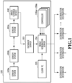
- FIG 1 is a diagram showing an example of the configuration of an image processing system that generates and distributes a virtual viewpoint image.
- An image processing system 100 includes sensor systems 101a to 101n, an image storage device 102, a database server 103, an image generation server 104, a client PC 105, and controllers 106a to 106m. In the following, each unit configuring the image processing system 100 is explained.
- the sensor systems 101a to 101n are arranged so as to surround a three-dimensional space, which is an image capturing-target area such as a stadium.
- On sensor system has at least one camera.
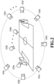
- FIG 2 shows an installation example of the sensor systems 101a to 101n.
- a field within a stadium and players and a ball located thereon are taken as objects and the N sensor systems 101a to 101n are arranged so as to surround them.
- Each of the sensor systems 101a to 101n has a camera and a microphone (not shown schematically).
- Each camera of each of the sensor systems 101a to 101n captures the same object in synchronization.
- An aggregate of a plurality of images whose viewpoints are different, which is obtained by performing image capturing with each camera from directions different from one another is a multi-viewpoint image. Further, each microphone, not shown schematically, collects voice in synchronization. For simplification of explanation, description of voice is omitted, but basically, images and voice are processed together.
- the image storage device 102 acquires a multi-viewpoint image, voice, and a time code that is attached at the time of image capturing from the sensor systems 101a to 101n and stores them in the database server 103. It may also be possible to perform image processing, for example, such as foreground/background separation processing, for the multi-viewpoint image and store it along with results thereof in the database server 103.
- the controllers 106a to 106m are input devices for each user to operate virtual cameras 210a to 210m and for example, a joystick, tablet, head-mounted display (HMD), or the like is used.
- a virtual viewpoint image is generated in the image generation server 104.
- the configuration is such that a plurality of operators uses the plurality of the controllers 106a to 106m at the same time and sets different virtual viewpoints independently of one another.
- the configuration may be one in which, for example, it is possible to designate a plurality of different virtual viewpoints with one tablet.
- controller 106 In the following explanation, in a case where an arbitrary one of the controllers 106a to 106m is described, this is described as “controller 106" and in a case where an arbitrary one of the virtual cameras 210a to 210m is described, this is described as “virtual camera 210".
- the client PC 105 is an information processing apparatus for providing information necessary for an operator or the like to generate and distribute a virtual viewpoint image to the image generation server 104.
- An operator creates information (in the following, called "instruction information") designating the number of virtual viewpoint images to be generated, the projection scheme that is applied at the time of generation, the output destination (distribution destination) of the generated virtual viewpoint image, and the like by using a user interface, to be described later, and sends the instruction information to the image generation server 104.
- the image generation server 104 generates virtual viewpoint images by a variety of projection schemes from the multi-viewpoint image acquired from the database server 103 in accordance with the instruction information that is sent from the client PC 105. At that time, the virtual viewpoints set by the controllers 106a to 106m are used. Then, the image generation server 104 outputs the one or more generated virtual viewpoint images to designated distribution destinations A to Z.
- the distribution destination for example, there are a moving image sharing site, SNS, broadcasting center, public viewing and the like.
- the moving image sharing site and SNS both the live distribution scheme and the on-demand distribution scheme are compatible, and therefore, an operator designates the projection scheme in accordance with the distribution aspect.
- the live distribution is distribution to broadcast live real time and the on-demand distribution is distribution that enables a user to view accumulated data as needed. It is possible for a viewer to easily view the live distribution or the on-demand distribution by connecting to the moving image sharing site or SNS by using a smartphone or the like.
- the above is the outline of each element configuring the image processing system 100.
- the above-described system configuration is an example and for example, it may also be possible to implement the client PC 105 and the image generation server 104 by one computer. Further, for example, the client PC 105 and the controller 106 may be configured into one unit.
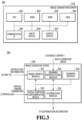
- FIG 3(a) shows the hardware configuration of the image generation server 104
- FIG 3(b) shows the software configuration of the image generation server 104.
- the hardware configuration is explained and next, the software configuration is explained.
- the image generation server 104 includes hardware that a general information processing apparatus has, that is, a CPU 301, a RAM 302, a ROM 303, an HDD 304, a communication I/F 305, an input device 306, and an output device 307.
- the CPU 301 is a processor that centralizedly controls each unit of the image generation server 104 by executing various programs stored in the ROM 303 by using the RAM 302 as a work memory. By the CPU 301 executing various programs, the function of each processing module shown in FIG 3(b) is implemented.
- the RAM 302 temporarily stores programs read from the ROM 303, operation results and the like.
- the ROM 303 stores programs, such as an OS, that do not need to be changed and data.
- the HDD 304 is a large-capacity storage device that stores the multi-viewpoint image read from the database server 103, the generated virtual viewpoint image and the like and may be, for example, an SSD or the like.
- the communication I/F 305 is compatible with the communication standard, such as Ethernet and USB, and performs communication with the database server 103, the client PC 105, and the controllers 106a to 106m.
- the input device 306 is a keyboard or a mouse, for an operator to perform various input operations.
- the output device 307 is a display device, such as a monitor, that displays information (UI screen and the like) necessary for an operator. In a case where, for example, a touch panel device is adopted as the output device 307, the touch panel display functions also as the input device 306 described above.
- the above-described hardware configuration is also comprised by, for example, the client PC 105.
- the image generation server 104 has five processing modules: a main control module 311, a drawing preprocessing module 312, a virtual viewpoint complementation module 313, a drawing module 314, and a distribution module 315. Explanation is given on the assumption that the image generation server 104 of the present embodiment generates virtual viewpoint images in accordance with one or more designated projection schemes among the four kinds of predetermined projection scheme, that is, the 2D scheme, the 3D scheme, the panorama scheme, and the 3D panorama scheme described previously.
- the projection schemes that can be designated are not limited to the above-described four kinds. As will be described later, the number of virtual viewpoints indicated by the viewpoint information that is used for the generation of virtual viewpoint images is different for different projection schemes.
- the main control module 311 is a module that plays a main role at the time of generating a virtual viewpoint image in accordance with the instruction information described previously and gives various instructions to the other processing modules. For example, in a case where the 3D scheme is designated, only the virtual viewpoint that is set by the controller 106 is not enough, and therefore, the main control module 311 instructs the virtual viewpoint complementation module 313 to complement a virtual viewpoint that is lacking. Then, the main control module 311 instructs the drawing module 314 to perform drawing processing using the two virtual viewpoints (virtual viewpoint set by a user with the controller 106 and virtual viewpoint obtained by the above-described complementation).
- the main control module 311 generates one virtual viewpoint image by the 3D scheme by performing composition processing for the drawing processing results (two images corresponding to the two virtual viewpoints) received from the drawing module 314. It is possible for the main control module 311 to generate and distribute a plurality of virtual viewpoint images by performing the series of processing such as this both simultaneously and in parallel in accordance with the number of virtual viewpoint images to be generated designated in the instruction information from the client PC 105.
- the drawing preprocessing module 312 acquires a multi-viewpoint image from the database server 103 by designating the time code at the time of image capturing.
- This multi-viewpoint image is obtained by each camera of the sensor systems 101a to 101n performing synchronous image capturing and stored in the database server 103 by the image storage apparatus 102.
- the drawing preprocessing module 312 also performs processing to generate data (three-dimensional model) indicting the three-dimensional shape of the foreground and the background, which is used in the drawing processing (rendering) in the drawing module 314, from the multi-viewpoint image.
- This three-dimensional model is generated by using a shape estimation method (for example, Visual Hull and the like) and configured by, for example, a point cloud.
- the configuration may be one in which the generation of the three-dimensional model is performed by another apparatus, for example, such as the image storage apparatus 102, and the drawing preprocessing module 312 acquires the three-dimensional model generated by another apparatus along with the multi-viewpoint image.
- the virtual viewpoint complementation module 313 acquires the viewpoint information (in the following, also described as "virtual camera parameter") specifying the position and orientation of each of the virtual cameras 210a to 210m, which is output by each of the controllers 106a to 106m.
- This viewpoint information may include information on, for example, magnification (zoom), not only the positions and orientations of the virtual cameras 210a to 210m.
- the number of virtual viewpoints necessary for the generation of one virtual viewpoint image is different depending on the projection scheme thereof. For example, in a case where the designated projection scheme is the 2D scheme, one virtual viewpoint is enough.
- the virtual viewpoint complementation module 313 complements the number of necessary virtual viewpoints in accordance with the projection scheme designated in the instruction information based on the virtual viewpoint according to the viewpoint information that is input from the controller 106. In this manner, the viewpoint information on the virtual viewpoint that is lacking is generated. This complementation of the virtual viewpoint will be described later.
- the drawing module 314 performs drawing by the perspective projection for the three-dimensional model of the foreground and the background based on one or a plurality of virtual viewpoints specified in the viewpoint information received from the virtual viewpoint complementation module 313. Specifically, the drawing module 314 performs processing to select a multi-viewpoint image to be used for each point configuring the three-dimensional model and acquires an appropriate pixel value in the selected multi-viewpoint image based on the virtual viewpoint and perform coloring. The drawing results are sent to the main control module 311.
- the distribution module 315 transmits the virtual viewpoint image generated as described above to a designated distribution destination.
- the distribution destinations of the plurality of virtual viewpoint images in accordance with the plurality of projection schemes may be different from one another, or at least part of the distribution destinations may be the same.
- the virtual viewpoint image that is distributed by the image generation server 104 is represented as "stream" and the number of distributions as "number of streams".
- the image generation server 104 of the present embodiment is characterized by generating one or a plurality of virtual viewpoint images from a common multi-viewpoint image by applying a variety of projection schemes and transmitting them to one or a plurality of distribution destinations (multi-stream output). According to the method such as this, it is possible to efficiently respond to requests of a variety of users. For example, in a case where an image of the 3D scheme and an image of the panorama scheme are provided by the conventional method using a normal captured image, which is not a virtual viewpoint image, the captured image that is necessary for each image is different.
- a captured image for the right eye and a captured image for the left eye are necessary, that is, two image whose image capturing positions are different by several centimeters and whose image capturing directions are substantially the same are necessary.
- a panorama image of 360° a large number of captured images whose image capturing directions are different from one another, or a super wide angle (fisheye) captured image is necessary. Consequently, in order to provide images in a plurality of different formats to a user, the time and effort for performing image capturing the number of times corresponding to the number of formats are necessary.
- the image generation server 104 of the present embodiment it is possible for the image generation server 104 of the present embodiment to generate and provide images in a variety of formats by acquiring in advance a common multi-viewpoint image that does not depend on the format of the image to be provided and using this. Further, it is possible to provide images in a variety of formats in accordance with a virtual viewpoint designated arbitrarily by a user, which cannot be implemented with normal captured images.
- the virtual viewpoint that is set by an operator is explained by taking a case as an example where the game of soccer in a stadium is the image capturing scene.
- the coordinate system representing the three-dimensional space of the image capturing target is explained, which is the reference in a case where a virtual viewpoint is set.
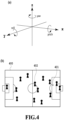
- FIG 4(a) shows a Cartesian coordinate system that represents a three-dimensional space by three axes, that is, X-axis, Y-axis, and Z-axis, which is used in the present embodiment.
- This Cartesian coordinate system is set to each object shown in FIG 4(b) , that is, a field 400, a ball 401, a player 402 and the like existing thereon. Further, it may also be possible to set the Cartesian coordinate system to facilities within the stadium, such as an inspector stand and a signboard. Specifically, first, the origin (0, 0, 0) is set at the center of the filed 400.
- the X-axis is set in the direction of the long side of the field 400
- the Y-axis is set in the direction of the short side of the field 400
- the Z-axis is set in the direction vertical to the field 400.
- the direction of each axis is not limited to these.
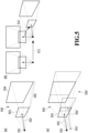
- the position and orientation of the virtual camera 210 are designated.
- a vertex 501 indicates the position of the virtual camera 210 and a vector 502 in the line-of-sight direction, whose starting point is the vertex 501, indicates the orientation of the virtual camera 210.
- the position of the virtual camera is represented by components (x, y, z) of each axis and the orientation of the virtual camera 210 is represented by a unit vector whose component of each axis is taken as a scalar. It is assumed that the vector representing the orientation of the virtual camera 210 passes through the center points of a forward clip plane 503 and a backward clip plane 504.
- the view frustum of the virtual viewpoint which is the projection range (drawing range) of a three-dimensional model, is a space 505 sandwiched by the forward clip plane 503 and the backward clip plane 504.
- FIG 5(b) is a diagram explaining the movement of the virtual viewpoint.
- a broken-line arrow 511 indicates the movement of the virtual viewpoint and a broken-line arrow 512 indicates the rotation of the moved virtual viewpoint.
- the movement of the virtual viewpoint is represented by the components (x, y, z) of each axis and the rotation of the virtual viewpoint is represented by yaw that is the rotation about the Z-axis, pitch that is the rotation about the X-axis, and roll that is the rotation about the Y-axis.
- the movement and rotation of the virtual viewpoint such as these are used for complementation of the virtual viewpoint, to be explained next, in addition to the use for the manipulation of the virtual camera by the controllers 106a to 106m.
- the complementation of the virtual viewpoint is processing to generate the virtual viewpoint that is lacking of the two or more virtual viewpoints necessary in a case where the projection scheme is the 3D scheme or the panorama scheme based on the virtual viewpoint set by the controller 106. Due to this, for example, in a case of the 3D scheme, two virtual viewpoints in the relationship of both-eye disparity are obtained.
- the virtual viewpoint that is obtained by this complementation is a virtual viewpoint different from any of the plurality of virtual viewpoints set by the plurality of the controllers 106a to 106m.
- FIG 5(c) is a diagram explaining the complementation of the virtual viewpoint in a case where the 3D scheme is designated.
- virtual camera parameters that take the position of the virtual camera as the vertex 501 of the quadrangular pyramid 500 and the orientation thereof as the vector 502 are input to the virtual viewpoint complementation module 313.
- the movement and rotation described previously are performed for the virtual viewpoint specified by the input virtual camera parameters and thereby another virtual viewpoint that establishes the relationship of both-eye disparity with the virtual viewpoint is generated.
- a virtual viewpoint that takes the position of the virtual camera 210 as a vertex 501' of a quadrangular pyramid 500' and the orientation thereof as a vector 502' is newly generated.
- a plurality of positions for example, positions shifted at predetermined intervals on each axis of X, Y, and Z
- One virtual viewpoint image of the 3D scheme is obtained by performing drawing processing that takes, among the two virtual viewpoints thus obtained, the virtual viewpoint indicated by the quadrangular 500 as the virtual viewpoint for the left eye and the virtual viewpoint indicated by the quadrangular 500' as the virtual viewpoint for the right eye and arranging the images of the drawing results respectively, for example, side by side and composting them.
- the virtual viewpoint complementation module 313 complements the number of virtual viewpoints necessary in the designated projection scheme from the virtual viewpoint set by one of the controllers 106.
- the virtual viewpoint complementation method is different for each projection scheme.
- the complementation method in a case of the 3D scheme is as described above, but in a case of the panorama scheme, the number of virtual viewpoints necessary for covering the range of 360 degrees at the maximum with the virtual viewpoint set by the controller 106 being taken as a reference. For example, in a case where the number of virtual viewpoints necessary for covering the entire circumference of 360 degrees is six, the remaining five virtual viewpoints are complemented by moving and rotating the reference virtual viewpoint that is set by the controller 106 so that the drawing range of each virtual viewpoint is adjacent to one another.
- the amount of movement and the amount of rotation at this time it may also be possible for a user to designate appropriate values via a UI screen, not shown schematically, as in the case of the 3D scheme, or apply predetermined values prepared in advance. Further, it may also be possible to find an appropriate amount of movement and amount of rotation by using an LUT prepared in advance. Furthermore, it may also be possible to generate another virtual viewpoint by changing only the orientation without changing the position of the reference virtual viewpoint. By compositing the images corresponding to the six virtual viewpoints thus generated, respectively, a virtual viewpoint image of the panorama scheme is obtained.
- the 3D panorama scheme is the combination of the 3D scheme and the panorama scheme.
- two images of the above-described panorama scheme are generated so that the both-eye disparity is obtained in order to implement a stereoscopic view based on the both-eye disparity of the panorama image.
- the reason it is possible to freely perform the complementation of the virtual viewpoint in accordance with each projection scheme as described above is that the multi-viewpoint image obtained by performing image capturing of an object from every direction with a plurality of cameras is obtained in advance. Even in a case where the object that spreads to a wide range, such as the field of the stadium, is the target, it is possible to complement another virtual viewpoint required by a designated projection scheme based on the information on the virtual camera that is set at an arbitrary position and with an arbitrary orientation within the target three-dimensional space.
- the virtual viewpoint image of the 3D scheme may be generated by taking the virtual viewpoint corresponding to the virtual viewpoint image of the 2D scheme as a reference and the virtual viewpoint corresponding to the virtual viewpoint image of the 2D scheme and the virtual viewpoint that is the reference of the virtual viewpoint image of the 3D scheme may be different.
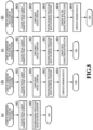
- FIG 6(a) and FIG 6(b) are diagrams showing an example of a UI screen for a user to create instruction information by designating the projection scheme and the distribution destination, which is displayed on a monitor of the client PC 105, or the like.
- FIG 6(a) shows a main screen 600 and FIG 6(b) shows a sub-screen for detailed setting. First, the main screen 600 is explained.
- a setting list 610 for inputting information necessary for the generation and distribution of one virtual viewpoint image is displayed on the main screen 600.
- three setting lists that is, the setting list 610 and setting lists 620 and 630 are displayed and this means that the New Creation button 601 is pressed down three times.
- a Delete button 602 is used in a case where an arbitrary setting list is deleted
- an OK button 603 is used in a case where the creation of a setting list is completed
- a Cancel button 604 is used in a case where the input operation of setting is aborted.
- explanation is given by taking a case as an example where three virtual viewpoint images are generated by the projection schemes different from one another and those virtual viewpoint images are output to four different distribution destinations.
- the instruction information designating details of the generation and distribution of the virtual viewpoint images is transmitted to the image generation server 104. It may also be possible to display each setting list as a sub-screen separate from the main screen 600. Further, it may also be possible to provide the OK button 603 in each of the plurality of setting lists. In this case, it is possible to give instructions to generate and distribute the virtual viewpoint image for each setting list.
- setting items 611 to 615 for designating main parameters necessary for the generation of each virtual viewpoint image, a detailed setting button 616, a state display field 617, and a thumbnail display field 618 exist, respectively. In the following, each element configuring the setting list is explained in order.
- the projection scheme is designated.
- the four kinds of projection scheme of the 2D scheme, the 3D scheme, the panorama scheme, and the 3D panorama scheme are displayed in a pulldown menu and an operator selects one in the menu.
- "3D scheme” is designated
- "panorama scheme” is designated
- "3D panorama scheme” is designated.
- the distribution destination is designated.
- the distribution destination includes a moving image sharing site, SNS, TV station broadcast center, public viewing and the like. It may also be possible to configure the setting item 612 by displaying the contents of distribution destination candidates created in advance in a pulldown menu and causing an operator to select one of them, or configure the setting item 612 so that it is possible for an operator to directly input the distribution destination address, such as URL.
- the moving image sharing site is not limited to a specific one and it is possible to designate a plurality of different moving image sharing sites. Furthermore, even for the same moving image sharing site, it is also possible to designate different URLs or the like. At that time, the display is produced by using a name that can identify each site.
- the distribution format and the time code are designated.
- the time code which is time information at the time of image capturing.
- the time code By making a request for a multi-viewpoint image to the database server 103 by designating the time code, it is possible to acquire the target data that can be identified uniquely.
- the on-demand distribution and the live distribution are displayed in a pulldown menu and an operator selects one in the menu. Then, in a case of the on-demand distribution, the start time code and the end time code are further designated.
- the virtual viewpoint image for the on-demand distribution is generated by using the multi-viewpoint image that can be identified by the start time code and the end time code.
- the time code at this time is designated by the format, for example, such as "2018/08/30 15:00:00:00 - 2018/08/30 15:30:00:20", and includes year, month, day, time, frame number, and the like.
- the virtual viewpoint image that is generated in accordance with the time code and distributed on demand is used, for example, for replay reproduction of a highlight scene.
- from the image capturing with each camera up to the generation and distribution of the virtual viewpoint image are processed real time.
- the method in which an operator designates the time code manually is not realistic. Consequently, in a case where the live distribution is selected, by selecting "Live" that is the character representation indicating the live distribution, the designation is completed and it is not necessary to designate the start and end time codes.
- the image generation server 104 automatically designates the most recent time code immediately after being stored sequentially and acquires the multi-viewpoint image from the database server 103.
- the multi-viewpoint image obtained by image capturing with each camera is acquired sequentially and the virtual viewpoint image is generated real time and output sequentially to the designated distribution destination. It is also possible to add the on-demand distribution by a separate stream on the way of the live distribution.
- the data format of the stream that is output from the image generation server 104 specifically, the kind of distribution protocol or the kind of video file format is specified. It is desirable to link the setting item 614 with the setting item 613 described above. That is, in a case where the live distribution is designated in the setting item 613 of each setting list, protocols for streaming, for example, such as RTMP (Real Time Message Protocol) and HLS (HTTP Live Streaming), are displayed as alternatives and an operator is caused to select therefrom. Further, in a case where the on-demand distribution is designated, video file formats, such as MP4, AVI, and MOV, are displayed as alternatives and an operator is caused to select therefrom. In the example in FIG 6(a) , in the setting lists 610 and 620 in which the live distribution is designated, "RTMP" is designated and in the setting list 630 in which the on-demand distribution is designated, "MP4" is designated.
- RTMP Real Time Message Protocol
- HLS HTTP Live Streaming
- information for designating the controller 106 having set the virtual viewpoint that is used to generate the multi-viewpoint image is designated.
- An operator selects one from the input devices, such as a joystick and a tablet, displayed as alternatives.
- an identifier is attached and here, by designating the identifier, which controller is used for the generation of the multi-viewpoint image is designated.
- FIG 6(a) by attaching an alphabet letter to the kind name of the controller, such as "joystick A" and "tablet A", it is made possible to identify the controller. It is also possible to designate the same identifier for the generation of a plurality of virtual viewpoint images.
- the detailed setting button 616 is a button for displaying the sub-screen for detailed setting.
- the sub-screen for detailed setting will be described later.
- a character string for example, “during distribution”, “completed”, “error” and the like
- “during distribution” indicates that the virtual viewpoint image is being output to the designated distribution destination
- “completed” indicates that the generation and distribution processing is completed
- "error” indicates that an error has occurred during the generation and distribution.
- the contents of the state display are not limited to the three contents described above.
- the thumbnail image of the virtual viewpoint image being processed is displayed.
- the thumbnail image By viewing the thumbnail image, it is possible for an operator to intuitively grasp whether the contents designated in each setting item are as those intended or whether the processing is normal.
- a sentence or the like indicating that an error has occurred is displayed.
- the UI screen shown in FIG 6(a) is merely an example and any UI screen may be used as long as it is possible to designate a desired projection scheme and designate the generation and the distribution destination of one or a plurality of virtual viewpoint images.
- a sub-screen 640 for detailed setting shown in FIG 6(b) is explained, which is displayed in a case where the detailed setting button 616 on the main screen 600 is pressed down.
- the sub-screen 640 detailed information relating to the generation and distribution of a virtual viewpoint image is set.
- a setting field 641 the resolution of a virtual viewpoint image that is generated is designated. For example, it is possible to designate FHD (Full HD), 4K, 8K and the like and an operator selects one of these displayed as alternatives.
- the frame rate of a virtual viewpoint image that is generated is designated. For example, it is possible to designate 29.97 fps, 30 fps, 59.94 fps, 60 fps and the like and an operator selects one of these displayed as alternatives.
- the encode method for a virtual viewpoint image that is output is designated. For example, it is possible to designate H.264, H.265, HEVC and the like and an operator selects one of these displayed as alternatives. It may also be possible to configure the setting fields 641 to 643 so that an operator can input an arbitrary numerical value directly in place of designating one of alternatives.
- a setting field 644 the contents designated in the setting item 614 (output data format) on the main screen 600 described previously are set.
- “RTMP” is also set in the setting field 644.
- an adjacent input field 645 the URL of the RTMP server, which is the output destination thereof, is input.
- "MP4" is also set in the setting field 644.
- the adjacent input field 645 the path, API or the like of the file server, which is the output destination thereof, is input.
- the Add button 646 is pressed down once and in a setting field 644' relating to another distribution destination, "RTMP" is input and in an input field 645' thereof, the URL thereof is input.
- the setting field 644 on the sub-screen 640 and the setting item 614 on the main screen 600 are linked and in a case where the contents of the setting field 644 are changed, the contents of the setting item 614 are also changed accordingly.
- HLS high-sity
- an operator creates the above-described instruction information by designating various items relating to the generation and distribution of a virtual viewpoint image and transmits the instruction information to the image generation server 104. Then, in the example in FIG 6(a) , a total of three virtual viewpoint images are generated based on the virtual viewpoints from the different controllers 106 in the different projection schemes, respectively, and output to the different distribution destinations, respectively. In addition to this, it is also possible to generate a plurality of virtual viewpoint images using the same projection scheme but using the different controller 106 that sets the virtual viewpoint. At this time, it is sufficient to designate the common projection scheme in the setting item 611 of each setting list and designate the identifier of the different controller 106 in the setting item 615.
- the live distribution and the on-demand distribution are combined, but it is also possible to distribute all the streams live. Further, it is also possible to archive the virtual viewpoint image generated with the same setting contents during the live distribution and set the virtual viewpoint image so as to be output as the on-demand distribution during the live distribution or after the live distribution is completed.
- FIG 7(a) is a flowchart showing a rough flow of the generation and distribution processing of a virtual viewpoint image.
- the series of processing is implemented by the CPU 301 executing a predetermined program to operate each processing module shown in FIG 3(b) .
- the main control module 311 receives the instruction information created for each setting list described previously from the client PC 105.
- the main control module 311 instructs the drawing preprocessing module 312 to acquire a multi-viewpoint image based on the received instruction information.
- the drawing preprocessing module 312 is instructed to acquire the multi-viewpoint image corresponding to the time code designated in each setting list.
- the drawing preprocessing module 312 having received the instructions acquires the multi-viewpoint image from the database server 103 by designating the time code based on the contents of the setting item 613 within the setting list.
- each processing module operates under the control of the main control module 311 and generates the virtual viewpoint images corresponding in number to the designated number in accordance with the instruction information and outputs the virtual viewpoint images to the designated distribution destination.
- the instruction information includes a plurality of setting lists
- the series of processing based on each setting list may be performed in parallel or sequentially. Details of the generation and distribution of a virtual viewpoint image at this step are explained with reference to another flow shown in FIG. 7(b) .
- a moving image is premised, and therefore, the flow shown in FIG 7(b) is performed for each frame.
- the main control module 311 specifies the projection scheme designated in the processing-target setting list and determines the step to which the processing advances next. Specifically, in a case where the 2D scheme is designated, the processing advance to S712, in a case where the 3D scheme is designated, the processing advances to S714, in a case where the panorama scheme is designated, the processing advances to S716, and in a case where the 3D panorama scheme is designated, the processing advances to S718, respectively.
- the processing to generate a virtual viewpoint image of the 2D scheme is performed.
- the generated virtual viewpoint image of the 2D scheme is output to the distribution destination designated in the setting list.
- the processing to generate a virtual viewpoint image of the 3D scheme is performed and at S715, the virtual viewpoint image of the 3D scheme is output to the distribution destination designated in the setting list.
- the processing to generate a virtual viewpoint image of the panorama scheme is performed and at S717, the virtual viewpoint image of the panorama scheme is output to the distribution destination designated in the setting list.
- the processing to generate a virtual viewpoint image of the 3D panorama scheme is performed and at S719, the virtual viewpoint image of the 3D panorama scheme is output to the distribution destination designated in the setting list.
- the generation of the virtual viewpoint image in accordance with each projection scheme at S712, S714, S716, and S718 is explained with reference to another flow shown in FIG. 8(a) to FIG 8(d) .
- FIG 8(a) is a flowchart showing details of virtual viewpoint image generation by the 2D scheme.
- the virtual viewpoint complementation module 313 acquires virtual camera parameters from the controller 106 corresponding to the identifier designated in the setting list.
- the virtual camera parameters at least information specifying the position and orientation of the virtual camera is included.
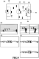
- FIG 9(a) shows an example of the virtual viewpoint that is set by taking a shot scene as a target.
- the virtual camera 210 is set at the position facing in the direction of the ball 401 from the outside of the penalty area as indicated by a mark 901 in the diagram shown in FIG 4(b) described previously and the virtual camera parameters corresponding to the mark 901 are acquired.
- each position of the virtual viewpoint on the Z-axis, which is set in the diagram shown in FIG 9(a) is fixed at the height of the line-of-sight of the player.
- the drawing module 314 performs drawing processing by the perspective projection from the virtual viewpoint indicated by the virtual camera parameters acquired at S801 by using the three-dimensional model of the foreground and the background provided from the drawing preprocessing module 312.
- the composition processing and the conversion processing are not necessary for the drawing results, and therefore, the drawing results are output as the virtual viewpoint image for distribution as they are.
- FIG. 9(b) shows the virtual viewpoint image of the 2D scheme corresponding to the virtual viewpoint at the mark 901 described above. In this case, the virtual viewpoint image from the line-of-sight of the player located outside the penalty area is obtained.
- FIG 8(b) is a flowchart showing details of virtual viewpoint image generation by the 3D scheme.
- the 3D scheme two image in a relationship of both-eye disparity are generated, and therefore, two virtual viewpoints are used.
- the virtual viewpoint complementation module 313 acquires virtual camera parameters from the controller 106 corresponding to the identifier designated in the setting list.
- the virtual camera 210 facing in the direction of the ball 401 from the position at which the goal keeper is located is set as indicated by a mark 902 in FIG 9(a) described above and the virtual camera parameters corresponding to the mark 902 are acquired.
- the virtual viewpoint complementation module 313 complements one another virtual viewpoint for implementing both-eye disparity based on the virtual camera parameters acquired at S811.
- the complementation method at this time is as already explained.
- the drawing module 314 performs drawing processing by the perspective projection for the virtual viewpoint acquired at S811 and the virtual viewpoint complemented at S812, respectively, by using the three-dimensional model of the foreground and the background provided from the drawing preprocessing module 312.
- the main control module 311 performs composition processing by arranging the drawing results at S813 (two images corresponding to the two virtual viewpoints with disparity) side by side and generates one virtual viewpoint image of the 3D scheme.
- the format in which two images with both-eye disparity are arranged side by side is called the side by side format.
- the virtual viewpoint image of the 3D scheme thus obtained is distributed.
- FIG 9(c) shows the virtual viewpoint image of the 3D scheme corresponding to the virtual viewpoint of the mark 902 described above.
- the virtual viewpoint image is an image in a case of being viewed from the same line-of-sight as that of the goal keeper.
- FIG 8(c) is a flowchart showing details of virtual viewpoint image generation by the panorama scheme.
- the panorama scheme in order to cover the entire circumference of 360 degrees at the maximum, and therefore, more virtual viewpoints than those of the 3D scheme are used.
- the virtual viewpoint complementation module 313 acquires virtual camera parameters from the controller 106 corresponding to the identifier designated in the setting list.
- the virtual camera 210 is set at the position facing in the direction of the ball 401 within the penalty area as indicated by a mark 903 in FIG 9(a) described above and the virtual camera parameters corresponding to the mark 903 are acquired.
- the virtual viewpoint complementation module 313 complements the number of virtual viewpoints necessary for the generation of images of the entire circumference by the panorama scheme based on the virtual camera parameters acquired at S821.
- the complementation method at this time is as already explained. In a case where the number of virtual viewpoints to be complemented is small, a panorama image in the range narrower than the entire circumference by an amount corresponding thereto is generated as a result.
- the drawing module 314 performs drawing processing by the perspective projection for each of the virtual viewpoint acquired at S821 and one or more virtual viewpoints complemented at S822 by using the three-dimensional model of the foreground and the background provided from the drawing preprocessing module 312.
- the main control module 311 performs conversion processing for the drawing results at S823 (a plurality of images corresponding to a plurality of virtual viewpoints) into the equirectangular projection and generates one virtual viewpoint image of the panorama scheme.
- the virtual viewpoint image of the panorama scheme thus obtained is distributed.
- FIG 9(d) shows the virtual viewpoint image of the panorama scheme corresponding to the virtual camera 210 at the mark 903 described above.
- the virtual viewpoint image is an image of the entire circumference of 360 degrees with the position 903 within the penalty area being taken as a center. It is possible for a user to view a scene in the direction the user desires to view in the entire circumference of 360 degrees with the virtual viewpoint position set by the controller 106 being taken as a center by using a smartphone or the like compatible with the panorama image display.
- FIG 8(d) is a flowchart showing details of virtual viewpoint image generation by the 3D panorama scheme.
- the 3D panorama scheme in order to cover the entire circumference of 360 degrees and implement both-eye disparity, the number of virtual viewpoints double that of the panorama scheme is used.
- the virtual viewpoint complementation module 313 acquires virtual camera parameters from the controller 106 corresponding to the identifier designated in the setting list.
- the virtual camera 210 is set at the position indicated by the mark 903 (see FIG 9(a) ) and the virtual camera parameters corresponding to the mark 903 are acquired.
- the virtual viewpoint complementation module 313 complements the number of virtual viewpoints necessary to cover the entire circumference by the 3D panorama scheme and for the generation of the image with both-eye disparity based on the virtual camera parameters acquired at S831.
- the complementation method at this time is as already explained.
- the drawing module 314 performs drawing processing by the perspective projection for the virtual viewpoint acquired at S831 and each of the plurality of virtual viewpoints complemented at S832 by using the three-dimensional model of the foreground and the background provided from the drawing preprocessing module 312.
- the main control module 311 divides the drawing results (a plurality of images corresponding to a plurality of virtual viewpoints) into images for the left eye and those for the right eye and performs conversion processing for each image group into the equirectangular projection. Due to this, the image of the panorama scheme is obtained for the left eye and for the right eye, respectively.
- the main control module 311 performs composition processing by arranging the drawing results at S834 (two images of the panorama scheme with disparity) one on top of another and generates one virtual viewpoint image of the 3D panorama scheme.
- the format in which two images with both-eye disparity are arranged one on top of another is called the top and bottom format.
- the virtual viewpoint image of the 3D panorama scheme thus obtained is distributed.
- FIG. 9(e) shows the virtual viewpoint image of the 3D panorama scheme corresponding to the virtual camera 210 at the mark 903 described above.
- the virtual viewpoint image is an image of the entire circumference of 360 degrees with the position 903 within the penalty area being taken as a center and having both-eye disparity.
- the above is the generation processing of the virtual viewpoint image by each projection scheme.
- the generation processing of the virtual viewpoint image by each projection scheme described above is an example and the generation processing is not limited to the contents described above. What is required is to be capable of generating the virtual viewpoint image in accordance with each projection scheme, and therefore, it is possible to change the processing order or the image format appropriately.
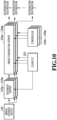
- the processing to generate and distribute a virtual viewpoint image in accordance with the above-described embodiment may be an overload depending on the number of virtual viewpoint images to be generated, the capacity of the multi-viewpoint image and the like.
- the capacity of the multi-viewpoint image becomes large, and therefore, it may become difficult to generate the virtual viewpoint image without a delay with only the one generation server 104 depending on the number of virtual viewpoint image to be generated.
- a distributed configuration for example, such as that shown in FIG 10 .
- a plurality of image generation servers 104a to 104m and a plurality of database servers 103a to 103m are prepared in advance and the database server and the image generation server are used among them, which are necessary to deal with the number of virtual viewpoint images to be generated designated in the instruction information.
- each of the image generation servers 104a to 104m is connected with each of the database servers 103a to 103m in a one-to-one manner. Then, by the image storage unit 102, the same multi-viewpoint image is stored in each of the database servers 103a to 103m and each of the image generation servers 104a to 104m acquires the multi-viewpoint image, respectively. Then, each of the image generation servers 104a to 104m generates one virtual viewpoint image in accordance with the instruction information received from the client PC 105 and outputs it to the designated distribution destination.
- Each of the database servers 103a to 103m stores the same multi-viewpoint image, and therefore, it may also be possible to configure each of the database servers 103a to 103m by a cache server.
- the configuration is such that the creation of the instruction information to each of the image generation servers 104a to 104m is performed by the one client PC 105, but a plurality of the client PCs 105 may exist.
- a dedicated management apparatus that controls the image generation servers 104a to 104m and the database servers 103a to 103m is provided and the management apparatus performs the allocation processing to each of the image generation servers 104a to 104m in place of the determination processing at S711 in the flow in FIG 7(b) .
- the management apparatus may also be possible to cause a tablet as each of the controllers 106a to 106m to have the function of the management apparatus.
- each of the image generation servers 104a to 104m may perform the distribution of the generated virtual viewpoint image or it may also be possible to design a configuration in which the management apparatus performs the distribution processing.
- the management apparatus determines the number of image generation servers to be used based on the format (projection scheme) of the virtual viewpoint image to be generated and distributed or the number of virtual viewpoint images. Then, the management apparatus controls the duplication and output of the multi-viewpoint image by the image storage device 102 so that the same multi-viewpoint image is stored in the database servers corresponding in number to the number of image generation servers to be used.
- the plurality of virtual viewpoint images generated by the plurality of image generation servers may be output to the distribution destinations different from one another.
- the present embodiment it is possible to generate a plurality of virtual viewpoint image whose projection schemes are different from one multi-viewpoint image and output the virtual viewpoint images to different distribution destinations. At that time, the projection scheme can be selected freely. Further, it is possible to set the virtual viewpoint corresponding to each virtual viewpoint image independently. Due to this, it is made possible to generate and distribute a variety of kinds of virtual viewpoint image in a case of being viewed from a variety of viewpoints in the three-dimensional space of an image capturing scene.
- a soccer game in a stadium as a target, it is possible to simultaneously distribute an image of the 3D scheme from the virtual viewpoint of the line-of-sight of a player, such as a goal keeper, to a public viewing, such as a movie theater, while distributing an image of the 2D scheme from the virtual viewpoint that follows a ball to the broadcast center of a TV station.
- a public viewing such as a movie theater
- an image of the panorama scheme and the 3D panorama scheme by which it is possible to view a highlight scene, such as a shot scene, within the penalty area around 360 degrees to a moving image distribution site or SNS.
- the application target of the present embodiment is not limited to a sports scene and for example, it is possible widely apply the present embodiment to a concert by a famous artist and it is made possible to provide a variety of new viewing experiences using virtual viewpoint images to a user.
Landscapes
- Engineering & Computer Science (AREA)
- Theoretical Computer Science (AREA)
- Physics & Mathematics (AREA)
- Multimedia (AREA)
- Signal Processing (AREA)
- General Physics & Mathematics (AREA)
- General Engineering & Computer Science (AREA)
- Human Computer Interaction (AREA)
- Computer Graphics (AREA)
- Computing Systems (AREA)
- Geometry (AREA)
- Computer Hardware Design (AREA)
- Software Systems (AREA)
- Processing Or Creating Images (AREA)
- Image Generation (AREA)
- Testing, Inspecting, Measuring Of Stereoscopic Televisions And Televisions (AREA)
- User Interface Of Digital Computer (AREA)
Applications Claiming Priority (2)
| Application Number | Priority Date | Filing Date | Title |
|---|---|---|---|
| JP2018213769A JP7237538B2 (ja) | 2018-11-14 | 2018-11-14 | 情報処理装置、それを含むシステム、情報処理方法、およびプログラム |
| PCT/JP2019/043996 WO2020100770A1 (ja) | 2018-11-14 | 2019-11-08 | 情報処理システム、情報処理方法、およびプログラム |
Publications (3)
| Publication Number | Publication Date |
|---|---|
| EP3882866A1 EP3882866A1 (en) | 2021-09-22 |
| EP3882866A4 EP3882866A4 (en) | 2022-08-10 |
| EP3882866B1 true EP3882866B1 (en) | 2024-05-15 |
Family
ID=70730893
Family Applications (1)
| Application Number | Title | Priority Date | Filing Date |
|---|---|---|---|
| EP19884420.1A Active EP3882866B1 (en) | 2018-11-14 | 2019-11-08 | Information processing system, information processing method, and program |
Country Status (6)
| Country | Link |
|---|---|
| US (2) | US20210266511A1 (enExample) |
| EP (1) | EP3882866B1 (enExample) |
| JP (1) | JP7237538B2 (enExample) |
| KR (1) | KR102551691B1 (enExample) |
| CN (1) | CN113016010B (enExample) |
| WO (1) | WO2020100770A1 (enExample) |
Families Citing this family (7)
| Publication number | Priority date | Publication date | Assignee | Title |
|---|---|---|---|---|
| JP7574565B2 (ja) * | 2020-07-31 | 2024-10-29 | 株式会社リコー | 通信端末、通信システム、通信方法、及びプログラム |
| US20230394745A1 (en) * | 2020-11-20 | 2023-12-07 | Sony Group Corporation | Information processing apparatus, information processing method, and information processing system |
| JP7690301B2 (ja) | 2021-02-26 | 2025-06-10 | キヤノン株式会社 | 情報処理装置、それを含むシステム、情報処理方法およびプログラム |
| JP7672842B2 (ja) | 2021-02-26 | 2025-05-08 | キヤノン株式会社 | 情報処理装置、情報処理方法、およびプログラム |
| US12206838B2 (en) * | 2021-09-24 | 2025-01-21 | Sony Group Corporation | View-independent multi-camera volumetric capture system |
| JP7746197B2 (ja) * | 2022-03-10 | 2025-09-30 | キヤノン株式会社 | 画像処理システム、画像処理方法及びコンピュータプログラム |
| EP4443273A1 (en) * | 2023-03-31 | 2024-10-09 | Canon Kabushiki Kaisha | Display control apparatus, display control method, and program |
Family Cites Families (28)
| Publication number | Priority date | Publication date | Assignee | Title |
|---|---|---|---|---|
| US5850352A (en) * | 1995-03-31 | 1998-12-15 | The Regents Of The University Of California | Immersive video, including video hypermosaicing to generate from multiple video views of a scene a three-dimensional video mosaic from which diverse virtual video scene images are synthesized, including panoramic, scene interactive and stereoscopic images |
| US5729471A (en) * | 1995-03-31 | 1998-03-17 | The Regents Of The University Of California | Machine dynamic selection of one video camera/image of a scene from multiple video cameras/images of the scene in accordance with a particular perspective on the scene, an object in the scene, or an event in the scene |
| EP1563882A4 (en) * | 2002-11-20 | 2006-01-18 | Sega Corp | GAME IMAGE DISPLAY CONTROL PROGRAM, GAME DEVICE, AND RECORDING MEDIUM |
| JP2006352539A (ja) | 2005-06-16 | 2006-12-28 | Sharp Corp | 広視野映像システム |
| US20070216782A1 (en) * | 2006-03-20 | 2007-09-20 | Donald Lee Chernoff | Method of processing and storing files in a digital camera |
| JP5456020B2 (ja) * | 2009-10-30 | 2014-03-26 | キヤノン株式会社 | 情報処理装置および方法 |
| US20110126160A1 (en) | 2009-11-23 | 2011-05-26 | Samsung Electronics Co., Ltd. | Method of providing 3d image and 3d display apparatus using the same |
| JP2011248723A (ja) | 2010-05-28 | 2011-12-08 | Sony Corp | 画像処理装置および方法、並びにプログラム |
| US9485497B2 (en) * | 2010-09-10 | 2016-11-01 | Reald Inc. | Systems and methods for converting two-dimensional images into three-dimensional images |
| WO2012091526A2 (ko) | 2010-12-31 | 2012-07-05 | 한국전자통신연구원 | 카메라를 구비한 휴대용 영상 통화 장치 및 그 방법 |
| KR101752691B1 (ko) * | 2011-12-14 | 2017-07-03 | 한국전자통신연구원 | 시점 선택이 가능한 3차원 가상 콘텐츠 동영상을 제공하는 장치 및 그 방법 |
| US9009092B2 (en) * | 2012-07-19 | 2015-04-14 | Microsoft Technology Licensing, Llc | Creating variations when transforming data into consumable content |
| KR101415147B1 (ko) * | 2012-08-10 | 2014-07-08 | 광운대학교 산학협력단 | 가상시점 영상 생성을 위한 경계 잡음 제거 및 홀 채움 방법 |
| KR102089976B1 (ko) | 2012-12-28 | 2020-03-18 | 삼성전자주식회사 | 엑스선 영상 장치, 엑스선 영상 생성 방법 및 3차원 영상 장치 |
| JP2014215828A (ja) | 2013-04-25 | 2014-11-17 | シャープ株式会社 | 画像データ再生装置、および視点情報生成装置 |
| JP6443654B2 (ja) * | 2013-09-26 | 2018-12-26 | Tianma Japan株式会社 | 立体画像表示装置、端末装置、立体画像表示方法、及びそのプログラム |
| KR101678861B1 (ko) | 2015-07-28 | 2016-11-23 | 엘지전자 주식회사 | 이동단말기 및 그 제어방법 |
| JP6164780B2 (ja) | 2015-09-30 | 2017-07-19 | 徹平 江里口 | 動画像処理装置、動画像処理方法、動画像処理プログラム及び動画像処理表示システム。 |
| EP3151554A1 (en) * | 2015-09-30 | 2017-04-05 | Calay Venture S.a.r.l. | Presence camera |
| WO2017154606A1 (ja) * | 2016-03-10 | 2017-09-14 | ソニー株式会社 | 情報処理装置および情報処理方法 |
| JP7054677B2 (ja) | 2016-08-10 | 2022-04-14 | パナソニック インテレクチュアル プロパティ コーポレーション オブ アメリカ | カメラワーク生成方法及び映像処理装置 |
| JP6539253B2 (ja) * | 2016-12-06 | 2019-07-03 | キヤノン株式会社 | 情報処理装置、その制御方法、およびプログラム |
| JP6482580B2 (ja) * | 2017-02-10 | 2019-03-13 | キヤノン株式会社 | 情報処理装置、情報処理方法、およびプログラム |
| JP7086522B2 (ja) * | 2017-02-28 | 2022-06-20 | キヤノン株式会社 | 画像処理装置、情報処理方法及びプログラム |
| US11218683B2 (en) | 2017-03-22 | 2022-01-04 | Nokia Technologies Oy | Method and an apparatus and a computer program product for adaptive streaming |
| JP6648061B2 (ja) | 2017-03-28 | 2020-02-14 | Kddi株式会社 | クライアント状態に応じた映像を配信する映像配信装置、システム、プログラム及び方法 |
| JP7249755B2 (ja) | 2018-10-26 | 2023-03-31 | キヤノン株式会社 | 画像処理システムおよびその制御方法、プログラム |
| JP7378243B2 (ja) | 2019-08-23 | 2023-11-13 | キヤノン株式会社 | 画像生成装置、画像表示装置および画像処理方法 |
-
2018
- 2018-11-14 JP JP2018213769A patent/JP7237538B2/ja active Active
-
2019
- 2019-11-08 CN CN201980075013.6A patent/CN113016010B/zh active Active
- 2019-11-08 KR KR1020217014249A patent/KR102551691B1/ko active Active
- 2019-11-08 WO PCT/JP2019/043996 patent/WO2020100770A1/ja not_active Ceased
- 2019-11-08 EP EP19884420.1A patent/EP3882866B1/en active Active
-
2021
- 2021-05-10 US US17/315,646 patent/US20210266511A1/en not_active Abandoned
-
2022
- 2022-06-24 US US17/848,426 patent/US11956408B2/en active Active
Also Published As
| Publication number | Publication date |
|---|---|
| JP2020080101A (ja) | 2020-05-28 |
| EP3882866A1 (en) | 2021-09-22 |
| KR102551691B1 (ko) | 2023-07-06 |
| WO2020100770A1 (ja) | 2020-05-22 |
| JP7237538B2 (ja) | 2023-03-13 |
| CN113016010A (zh) | 2021-06-22 |
| KR20210072086A (ko) | 2021-06-16 |
| CN113016010B (zh) | 2024-07-16 |
| US11956408B2 (en) | 2024-04-09 |
| EP3882866A4 (en) | 2022-08-10 |
| US20210266511A1 (en) | 2021-08-26 |
| US20220321856A1 (en) | 2022-10-06 |
Similar Documents
| Publication | Publication Date | Title |
|---|---|---|
| EP3882866B1 (en) | Information processing system, information processing method, and program | |
| US11019259B2 (en) | Real-time generation method for 360-degree VR panoramic graphic image and video | |
| CN106210861B (zh) | 显示弹幕的方法及系统 | |
| JP6849430B2 (ja) | 画像処理装置、画像処理方法、及びプログラム | |
| JP7249755B2 (ja) | 画像処理システムおよびその制御方法、プログラム | |
| JP2015114716A (ja) | 画像データ再生装置および画像データ生成装置 | |
| JP2019191989A (ja) | 仮想視点画像を生成するシステム、方法及びプログラム | |
| US11579746B2 (en) | Dynamic image capturing apparatus and method using arbitrary viewpoint image generation technology | |
| EP3621300B1 (en) | Display control device and display control method | |
| US12211140B2 (en) | Information processing apparatus, information processing method, and storage medium | |
| JP2021034885A (ja) | 画像生成装置、画像表示装置および画像処理方法 | |
| CN115686295A (zh) | 图像处理设备、图像处理方法和存储介质 | |
| CN115423916A (zh) | 基于xr技术的沉浸式互动直播构建方法、系统及介质 | |
| KR101752691B1 (ko) | 시점 선택이 가능한 3차원 가상 콘텐츠 동영상을 제공하는 장치 및 그 방법 | |
| JP6011567B2 (ja) | 情報処理装置、その制御方法、及びプログラム | |
| JP2015162117A (ja) | サーバ装置、プログラム、及び情報処理方法 | |
| KR20190058040A (ko) | Ip를 통한 멀티카메라 비디오 분배 및 결합 시스템 및 그 방법 | |
| JP2020074108A (ja) | 情報処理システム、その制御方法、及びプログラム | |
| JP5192442B2 (ja) | 映像生成装置、映像生成方法、映像生成プログラムおよびそのプログラムを記録したコンピュータ読み取り可能な記録媒体 | |
| JP2015162815A (ja) | 端末装置、及びプログラム | |
| JP2012128737A (ja) | 3d映像生成システム | |
| JP2023178007A (ja) | 情報処理装置、情報処理装置の制御方法、及びプログラム | |
| Zhou et al. | Streaming Location-Based Panorama Videos into Augmented Virtual Environment | |
| CN121126063A (zh) | 显示控制方法、装置、设备、介质及产品 | |
| JP2023003765A (ja) | 画像生成装置およびその制御方法、画像生成システム、ならびにプログラム |
Legal Events
| Date | Code | Title | Description |
|---|---|---|---|
| STAA | Information on the status of an ep patent application or granted ep patent |
Free format text: STATUS: THE INTERNATIONAL PUBLICATION HAS BEEN MADE |
|
| PUAI | Public reference made under article 153(3) epc to a published international application that has entered the european phase |
Free format text: ORIGINAL CODE: 0009012 |
|
| STAA | Information on the status of an ep patent application or granted ep patent |
Free format text: STATUS: REQUEST FOR EXAMINATION WAS MADE |
|
| 17P | Request for examination filed |
Effective date: 20210614 |
|
| AK | Designated contracting states |
Kind code of ref document: A1 Designated state(s): AL AT BE BG CH CY CZ DE DK EE ES FI FR GB GR HR HU IE IS IT LI LT LU LV MC MK MT NL NO PL PT RO RS SE SI SK SM TR |
|
| DAV | Request for validation of the european patent (deleted) | ||
| DAX | Request for extension of the european patent (deleted) | ||
| A4 | Supplementary search report drawn up and despatched |
Effective date: 20220713 |
|
| RIC1 | Information provided on ipc code assigned before grant |
Ipc: H04N 13/356 20180101ALI20220707BHEP Ipc: H04N 13/243 20180101ALI20220707BHEP Ipc: H04N 13/117 20180101ALI20220707BHEP Ipc: G06F 3/0487 20130101ALI20220707BHEP Ipc: G06F 3/0484 20130101ALI20220707BHEP Ipc: G06F 3/0481 20130101ALI20220707BHEP Ipc: G06T 19/00 20110101ALI20220707BHEP Ipc: G06T 15/20 20110101AFI20220707BHEP |
|
| GRAP | Despatch of communication of intention to grant a patent |
Free format text: ORIGINAL CODE: EPIDOSNIGR1 |
|
| STAA | Information on the status of an ep patent application or granted ep patent |
Free format text: STATUS: GRANT OF PATENT IS INTENDED |
|
| INTG | Intention to grant announced |
Effective date: 20231206 |
|
| RAP3 | Party data changed (applicant data changed or rights of an application transferred) |
Owner name: CANON KABUSHIKI KAISHA |
|
| RIN1 | Information on inventor provided before grant (corrected) |
Inventor name: OGASAWARA, TAKU |
|
| GRAS | Grant fee paid |
Free format text: ORIGINAL CODE: EPIDOSNIGR3 |
|
| GRAA | (expected) grant |
Free format text: ORIGINAL CODE: 0009210 |
|
| STAA | Information on the status of an ep patent application or granted ep patent |
Free format text: STATUS: THE PATENT HAS BEEN GRANTED |
|
| AK | Designated contracting states |
Kind code of ref document: B1 Designated state(s): AL AT BE BG CH CY CZ DE DK EE ES FI FR GB GR HR HU IE IS IT LI LT LU LV MC MK MT NL NO PL PT RO RS SE SI SK SM TR |
|
| REG | Reference to a national code |
Ref country code: CH Ref legal event code: EP |
|
| REG | Reference to a national code |
Ref country code: DE Ref legal event code: R096 Ref document number: 602019052416 Country of ref document: DE |
|
| REG | Reference to a national code |
Ref country code: IE Ref legal event code: FG4D |
|
| REG | Reference to a national code |
Ref country code: LT Ref legal event code: MG9D |
|
| REG | Reference to a national code |
Ref country code: NL Ref legal event code: MP Effective date: 20240515 |
|
| PG25 | Lapsed in a contracting state [announced via postgrant information from national office to epo] |
Ref country code: IS Free format text: LAPSE BECAUSE OF FAILURE TO SUBMIT A TRANSLATION OF THE DESCRIPTION OR TO PAY THE FEE WITHIN THE PRESCRIBED TIME-LIMIT Effective date: 20240915 |
|
| PG25 | Lapsed in a contracting state [announced via postgrant information from national office to epo] |
Ref country code: BG Free format text: LAPSE BECAUSE OF FAILURE TO SUBMIT A TRANSLATION OF THE DESCRIPTION OR TO PAY THE FEE WITHIN THE PRESCRIBED TIME-LIMIT Effective date: 20240515 |
|
| PG25 | Lapsed in a contracting state [announced via postgrant information from national office to epo] |
Ref country code: FI Free format text: LAPSE BECAUSE OF FAILURE TO SUBMIT A TRANSLATION OF THE DESCRIPTION OR TO PAY THE FEE WITHIN THE PRESCRIBED TIME-LIMIT Effective date: 20240515 Ref country code: HR Free format text: LAPSE BECAUSE OF FAILURE TO SUBMIT A TRANSLATION OF THE DESCRIPTION OR TO PAY THE FEE WITHIN THE PRESCRIBED TIME-LIMIT Effective date: 20240515 |
|
| PG25 | Lapsed in a contracting state [announced via postgrant information from national office to epo] |
Ref country code: GR Free format text: LAPSE BECAUSE OF FAILURE TO SUBMIT A TRANSLATION OF THE DESCRIPTION OR TO PAY THE FEE WITHIN THE PRESCRIBED TIME-LIMIT Effective date: 20240816 |
|
| PG25 | Lapsed in a contracting state [announced via postgrant information from national office to epo] |
Ref country code: PT Free format text: LAPSE BECAUSE OF FAILURE TO SUBMIT A TRANSLATION OF THE DESCRIPTION OR TO PAY THE FEE WITHIN THE PRESCRIBED TIME-LIMIT Effective date: 20240916 |
|
| REG | Reference to a national code |
Ref country code: AT Ref legal event code: MK05 Ref document number: 1687536 Country of ref document: AT Kind code of ref document: T Effective date: 20240515 |
|
| PG25 | Lapsed in a contracting state [announced via postgrant information from national office to epo] |
Ref country code: NL Free format text: LAPSE BECAUSE OF FAILURE TO SUBMIT A TRANSLATION OF THE DESCRIPTION OR TO PAY THE FEE WITHIN THE PRESCRIBED TIME-LIMIT Effective date: 20240515 |
|
| PG25 | Lapsed in a contracting state [announced via postgrant information from national office to epo] |
Ref country code: ES Free format text: LAPSE BECAUSE OF FAILURE TO SUBMIT A TRANSLATION OF THE DESCRIPTION OR TO PAY THE FEE WITHIN THE PRESCRIBED TIME-LIMIT Effective date: 20240515 |
|
| PG25 | Lapsed in a contracting state [announced via postgrant information from national office to epo] |
Ref country code: AT Free format text: LAPSE BECAUSE OF FAILURE TO SUBMIT A TRANSLATION OF THE DESCRIPTION OR TO PAY THE FEE WITHIN THE PRESCRIBED TIME-LIMIT Effective date: 20240515 |
|
| PG25 | Lapsed in a contracting state [announced via postgrant information from national office to epo] |
Ref country code: PL Free format text: LAPSE BECAUSE OF FAILURE TO SUBMIT A TRANSLATION OF THE DESCRIPTION OR TO PAY THE FEE WITHIN THE PRESCRIBED TIME-LIMIT Effective date: 20240515 |
|
| PG25 | Lapsed in a contracting state [announced via postgrant information from national office to epo] |
Ref country code: LV Free format text: LAPSE BECAUSE OF FAILURE TO SUBMIT A TRANSLATION OF THE DESCRIPTION OR TO PAY THE FEE WITHIN THE PRESCRIBED TIME-LIMIT Effective date: 20240515 |
|
| PG25 | Lapsed in a contracting state [announced via postgrant information from national office to epo] |
Ref country code: PT Free format text: LAPSE BECAUSE OF FAILURE TO SUBMIT A TRANSLATION OF THE DESCRIPTION OR TO PAY THE FEE WITHIN THE PRESCRIBED TIME-LIMIT Effective date: 20240916 Ref country code: PL Free format text: LAPSE BECAUSE OF FAILURE TO SUBMIT A TRANSLATION OF THE DESCRIPTION OR TO PAY THE FEE WITHIN THE PRESCRIBED TIME-LIMIT Effective date: 20240515 Ref country code: NO Free format text: LAPSE BECAUSE OF FAILURE TO SUBMIT A TRANSLATION OF THE DESCRIPTION OR TO PAY THE FEE WITHIN THE PRESCRIBED TIME-LIMIT Effective date: 20240815 Ref country code: NL Free format text: LAPSE BECAUSE OF FAILURE TO SUBMIT A TRANSLATION OF THE DESCRIPTION OR TO PAY THE FEE WITHIN THE PRESCRIBED TIME-LIMIT Effective date: 20240515 Ref country code: LV Free format text: LAPSE BECAUSE OF FAILURE TO SUBMIT A TRANSLATION OF THE DESCRIPTION OR TO PAY THE FEE WITHIN THE PRESCRIBED TIME-LIMIT Effective date: 20240515 Ref country code: IS Free format text: LAPSE BECAUSE OF FAILURE TO SUBMIT A TRANSLATION OF THE DESCRIPTION OR TO PAY THE FEE WITHIN THE PRESCRIBED TIME-LIMIT Effective date: 20240915 Ref country code: HR Free format text: LAPSE BECAUSE OF FAILURE TO SUBMIT A TRANSLATION OF THE DESCRIPTION OR TO PAY THE FEE WITHIN THE PRESCRIBED TIME-LIMIT Effective date: 20240515 Ref country code: GR Free format text: LAPSE BECAUSE OF FAILURE TO SUBMIT A TRANSLATION OF THE DESCRIPTION OR TO PAY THE FEE WITHIN THE PRESCRIBED TIME-LIMIT Effective date: 20240816 Ref country code: FI Free format text: LAPSE BECAUSE OF FAILURE TO SUBMIT A TRANSLATION OF THE DESCRIPTION OR TO PAY THE FEE WITHIN THE PRESCRIBED TIME-LIMIT Effective date: 20240515 Ref country code: ES Free format text: LAPSE BECAUSE OF FAILURE TO SUBMIT A TRANSLATION OF THE DESCRIPTION OR TO PAY THE FEE WITHIN THE PRESCRIBED TIME-LIMIT Effective date: 20240515 Ref country code: BG Free format text: LAPSE BECAUSE OF FAILURE TO SUBMIT A TRANSLATION OF THE DESCRIPTION OR TO PAY THE FEE WITHIN THE PRESCRIBED TIME-LIMIT Effective date: 20240515 Ref country code: AT Free format text: LAPSE BECAUSE OF FAILURE TO SUBMIT A TRANSLATION OF THE DESCRIPTION OR TO PAY THE FEE WITHIN THE PRESCRIBED TIME-LIMIT Effective date: 20240515 Ref country code: RS Free format text: LAPSE BECAUSE OF FAILURE TO SUBMIT A TRANSLATION OF THE DESCRIPTION OR TO PAY THE FEE WITHIN THE PRESCRIBED TIME-LIMIT Effective date: 20240815 |
|
| PG25 | Lapsed in a contracting state [announced via postgrant information from national office to epo] |
Ref country code: DK Free format text: LAPSE BECAUSE OF FAILURE TO SUBMIT A TRANSLATION OF THE DESCRIPTION OR TO PAY THE FEE WITHIN THE PRESCRIBED TIME-LIMIT Effective date: 20240515 |
|
| PG25 | Lapsed in a contracting state [announced via postgrant information from national office to epo] |
Ref country code: EE Free format text: LAPSE BECAUSE OF FAILURE TO SUBMIT A TRANSLATION OF THE DESCRIPTION OR TO PAY THE FEE WITHIN THE PRESCRIBED TIME-LIMIT Effective date: 20240515 |
|
| PG25 | Lapsed in a contracting state [announced via postgrant information from national office to epo] |
Ref country code: CZ Free format text: LAPSE BECAUSE OF FAILURE TO SUBMIT A TRANSLATION OF THE DESCRIPTION OR TO PAY THE FEE WITHIN THE PRESCRIBED TIME-LIMIT Effective date: 20240515 |
|
| PG25 | Lapsed in a contracting state [announced via postgrant information from national office to epo] |
Ref country code: SK Free format text: LAPSE BECAUSE OF FAILURE TO SUBMIT A TRANSLATION OF THE DESCRIPTION OR TO PAY THE FEE WITHIN THE PRESCRIBED TIME-LIMIT Effective date: 20240515 Ref country code: RO Free format text: LAPSE BECAUSE OF FAILURE TO SUBMIT A TRANSLATION OF THE DESCRIPTION OR TO PAY THE FEE WITHIN THE PRESCRIBED TIME-LIMIT Effective date: 20240515 |
|
| PG25 | Lapsed in a contracting state [announced via postgrant information from national office to epo] |
Ref country code: SM Free format text: LAPSE BECAUSE OF FAILURE TO SUBMIT A TRANSLATION OF THE DESCRIPTION OR TO PAY THE FEE WITHIN THE PRESCRIBED TIME-LIMIT Effective date: 20240515 |
|
| PG25 | Lapsed in a contracting state [announced via postgrant information from national office to epo] |
Ref country code: SM Free format text: LAPSE BECAUSE OF FAILURE TO SUBMIT A TRANSLATION OF THE DESCRIPTION OR TO PAY THE FEE WITHIN THE PRESCRIBED TIME-LIMIT Effective date: 20240515 Ref country code: SK Free format text: LAPSE BECAUSE OF FAILURE TO SUBMIT A TRANSLATION OF THE DESCRIPTION OR TO PAY THE FEE WITHIN THE PRESCRIBED TIME-LIMIT Effective date: 20240515 Ref country code: RO Free format text: LAPSE BECAUSE OF FAILURE TO SUBMIT A TRANSLATION OF THE DESCRIPTION OR TO PAY THE FEE WITHIN THE PRESCRIBED TIME-LIMIT Effective date: 20240515 Ref country code: EE Free format text: LAPSE BECAUSE OF FAILURE TO SUBMIT A TRANSLATION OF THE DESCRIPTION OR TO PAY THE FEE WITHIN THE PRESCRIBED TIME-LIMIT Effective date: 20240515 Ref country code: DK Free format text: LAPSE BECAUSE OF FAILURE TO SUBMIT A TRANSLATION OF THE DESCRIPTION OR TO PAY THE FEE WITHIN THE PRESCRIBED TIME-LIMIT Effective date: 20240515 Ref country code: CZ Free format text: LAPSE BECAUSE OF FAILURE TO SUBMIT A TRANSLATION OF THE DESCRIPTION OR TO PAY THE FEE WITHIN THE PRESCRIBED TIME-LIMIT Effective date: 20240515 |
|
| PG25 | Lapsed in a contracting state [announced via postgrant information from national office to epo] |
Ref country code: IT Free format text: LAPSE BECAUSE OF FAILURE TO SUBMIT A TRANSLATION OF THE DESCRIPTION OR TO PAY THE FEE WITHIN THE PRESCRIBED TIME-LIMIT Effective date: 20240515 |
|
| REG | Reference to a national code |
Ref country code: DE Ref legal event code: R097 Ref document number: 602019052416 Country of ref document: DE |
|
| PLBE | No opposition filed within time limit |
Free format text: ORIGINAL CODE: 0009261 |
|
| STAA | Information on the status of an ep patent application or granted ep patent |
Free format text: STATUS: NO OPPOSITION FILED WITHIN TIME LIMIT |
|
| 26N | No opposition filed |
Effective date: 20250218 |
|
| PG25 | Lapsed in a contracting state [announced via postgrant information from national office to epo] |
Ref country code: SI Free format text: LAPSE BECAUSE OF FAILURE TO SUBMIT A TRANSLATION OF THE DESCRIPTION OR TO PAY THE FEE WITHIN THE PRESCRIBED TIME-LIMIT Effective date: 20240515 |
|
| REG | Reference to a national code |
Ref country code: DE Ref legal event code: R119 Ref document number: 602019052416 Country of ref document: DE |
|
| REG | Reference to a national code |
Ref country code: CH Ref legal event code: PL |
|
| PG25 | Lapsed in a contracting state [announced via postgrant information from national office to epo] |
Ref country code: MC Free format text: LAPSE BECAUSE OF FAILURE TO SUBMIT A TRANSLATION OF THE DESCRIPTION OR TO PAY THE FEE WITHIN THE PRESCRIBED TIME-LIMIT Effective date: 20240515 |
|
| PG25 | Lapsed in a contracting state [announced via postgrant information from national office to epo] |
Ref country code: LU Free format text: LAPSE BECAUSE OF NON-PAYMENT OF DUE FEES Effective date: 20241108 |
|
| REG | Reference to a national code |
Ref country code: CH Ref legal event code: PL |
|
| PG25 | Lapsed in a contracting state [announced via postgrant information from national office to epo] |
Ref country code: CH Free format text: LAPSE BECAUSE OF NON-PAYMENT OF DUE FEES Effective date: 20241130 |
|
| REG | Reference to a national code |
Ref country code: BE Ref legal event code: MM Effective date: 20241130 |
|
| PG25 | Lapsed in a contracting state [announced via postgrant information from national office to epo] |
Ref country code: SE Free format text: LAPSE BECAUSE OF FAILURE TO SUBMIT A TRANSLATION OF THE DESCRIPTION OR TO PAY THE FEE WITHIN THE PRESCRIBED TIME-LIMIT Effective date: 20240515 |
|
| PG25 | Lapsed in a contracting state [announced via postgrant information from national office to epo] |
Ref country code: DE Free format text: LAPSE BECAUSE OF NON-PAYMENT OF DUE FEES Effective date: 20250603 |
|
| PG25 | Lapsed in a contracting state [announced via postgrant information from national office to epo] |
Ref country code: BE Free format text: LAPSE BECAUSE OF NON-PAYMENT OF DUE FEES Effective date: 20241130 |
|
| PG25 | Lapsed in a contracting state [announced via postgrant information from national office to epo] |
Ref country code: FR Free format text: LAPSE BECAUSE OF NON-PAYMENT OF DUE FEES Effective date: 20241130 |
|
| PG25 | Lapsed in a contracting state [announced via postgrant information from national office to epo] |
Ref country code: IE Free format text: LAPSE BECAUSE OF NON-PAYMENT OF DUE FEES Effective date: 20241108 |
|
| PGFP | Annual fee paid to national office [announced via postgrant information from national office to epo] |
Ref country code: GB Payment date: 20251023 Year of fee payment: 7 |
|
| PG25 | Lapsed in a contracting state [announced via postgrant information from national office to epo] |
Ref country code: HU Free format text: LAPSE BECAUSE OF FAILURE TO SUBMIT A TRANSLATION OF THE DESCRIPTION OR TO PAY THE FEE WITHIN THE PRESCRIBED TIME-LIMIT; INVALID AB INITIO Effective date: 20191108 |
|
| PG25 | Lapsed in a contracting state [announced via postgrant information from national office to epo] |
Ref country code: CY Free format text: LAPSE BECAUSE OF FAILURE TO SUBMIT A TRANSLATION OF THE DESCRIPTION OR TO PAY THE FEE WITHIN THE PRESCRIBED TIME-LIMIT; INVALID AB INITIO Effective date: 20191108 |