WO2020100770A1 - 情報処理システム、情報処理方法、およびプログラム - Google Patents
情報処理システム、情報処理方法、およびプログラム Download PDFInfo
- Publication number
- WO2020100770A1 WO2020100770A1 PCT/JP2019/043996 JP2019043996W WO2020100770A1 WO 2020100770 A1 WO2020100770 A1 WO 2020100770A1 JP 2019043996 W JP2019043996 W JP 2019043996W WO 2020100770 A1 WO2020100770 A1 WO 2020100770A1
- Authority
- WO
- WIPO (PCT)
- Prior art keywords
- image
- virtual viewpoint
- virtual
- viewpoint
- information processing
- Prior art date
Links
- 230000010365 information processing Effects 0.000 title claims abstract description 25
- 238000003672 processing method Methods 0.000 title claims 4
- 238000003384 imaging method Methods 0.000 claims abstract description 15
- 238000000034 method Methods 0.000 description 135
- 238000009826 distribution Methods 0.000 description 79
- 238000012545 processing Methods 0.000 description 35
- 230000008569 process Effects 0.000 description 19
- 238000010586 diagram Methods 0.000 description 12
- 238000007781 pre-processing Methods 0.000 description 10
- 230000006870 function Effects 0.000 description 7
- 230000036544 posture Effects 0.000 description 7
- 230000000295 complement effect Effects 0.000 description 5
- 238000007726 management method Methods 0.000 description 5
- 238000009877 rendering Methods 0.000 description 5
- WBMKMLWMIQUJDP-STHHAXOLSA-N (4R,4aS,7aR,12bS)-4a,9-dihydroxy-3-prop-2-ynyl-2,4,5,6,7a,13-hexahydro-1H-4,12-methanobenzofuro[3,2-e]isoquinolin-7-one hydrochloride Chemical compound Cl.Oc1ccc2C[C@H]3N(CC#C)CC[C@@]45[C@@H](Oc1c24)C(=O)CC[C@@]35O WBMKMLWMIQUJDP-STHHAXOLSA-N 0.000 description 3
- 230000008859 change Effects 0.000 description 3
- 238000004891 communication Methods 0.000 description 3
- 230000004048 modification Effects 0.000 description 3
- 238000012986 modification Methods 0.000 description 3
- 238000005516 engineering process Methods 0.000 description 2
- 238000009434 installation Methods 0.000 description 2
- 230000002194 synthesizing effect Effects 0.000 description 2
- 230000015572 biosynthetic process Effects 0.000 description 1
- 238000004364 calculation method Methods 0.000 description 1
- 238000007796 conventional method Methods 0.000 description 1
- 210000003128 head Anatomy 0.000 description 1
- 238000003825 pressing Methods 0.000 description 1
- 230000004044 response Effects 0.000 description 1
- 238000000926 separation method Methods 0.000 description 1
- 239000013589 supplement Substances 0.000 description 1
- 238000003786 synthesis reaction Methods 0.000 description 1
- 230000008685 targeting Effects 0.000 description 1
- 230000000007 visual effect Effects 0.000 description 1
Images


Classifications
-
- G—PHYSICS
- G06—COMPUTING; CALCULATING OR COUNTING
- G06T—IMAGE DATA PROCESSING OR GENERATION, IN GENERAL
- G06T15/00—3D [Three Dimensional] image rendering
- G06T15/10—Geometric effects
- G06T15/20—Perspective computation
- G06T15/205—Image-based rendering
-
- H—ELECTRICITY
- H04—ELECTRIC COMMUNICATION TECHNIQUE
- H04N—PICTORIAL COMMUNICATION, e.g. TELEVISION
- H04N13/00—Stereoscopic video systems; Multi-view video systems; Details thereof
- H04N13/10—Processing, recording or transmission of stereoscopic or multi-view image signals
- H04N13/106—Processing image signals
- H04N13/111—Transformation of image signals corresponding to virtual viewpoints, e.g. spatial image interpolation
- H04N13/117—Transformation of image signals corresponding to virtual viewpoints, e.g. spatial image interpolation the virtual viewpoint locations being selected by the viewers or determined by viewer tracking
-
- G—PHYSICS
- G06—COMPUTING; CALCULATING OR COUNTING
- G06F—ELECTRIC DIGITAL DATA PROCESSING
- G06F3/00—Input arrangements for transferring data to be processed into a form capable of being handled by the computer; Output arrangements for transferring data from processing unit to output unit, e.g. interface arrangements
- G06F3/01—Input arrangements or combined input and output arrangements for interaction between user and computer
- G06F3/048—Interaction techniques based on graphical user interfaces [GUI]
- G06F3/0481—Interaction techniques based on graphical user interfaces [GUI] based on specific properties of the displayed interaction object or a metaphor-based environment, e.g. interaction with desktop elements like windows or icons, or assisted by a cursor's changing behaviour or appearance
-
- G—PHYSICS
- G06—COMPUTING; CALCULATING OR COUNTING
- G06F—ELECTRIC DIGITAL DATA PROCESSING
- G06F3/00—Input arrangements for transferring data to be processed into a form capable of being handled by the computer; Output arrangements for transferring data from processing unit to output unit, e.g. interface arrangements
- G06F3/01—Input arrangements or combined input and output arrangements for interaction between user and computer
- G06F3/048—Interaction techniques based on graphical user interfaces [GUI]
- G06F3/0484—Interaction techniques based on graphical user interfaces [GUI] for the control of specific functions or operations, e.g. selecting or manipulating an object, an image or a displayed text element, setting a parameter value or selecting a range
-
- G—PHYSICS
- G06—COMPUTING; CALCULATING OR COUNTING
- G06F—ELECTRIC DIGITAL DATA PROCESSING
- G06F3/00—Input arrangements for transferring data to be processed into a form capable of being handled by the computer; Output arrangements for transferring data from processing unit to output unit, e.g. interface arrangements
- G06F3/01—Input arrangements or combined input and output arrangements for interaction between user and computer
- G06F3/048—Interaction techniques based on graphical user interfaces [GUI]
- G06F3/0487—Interaction techniques based on graphical user interfaces [GUI] using specific features provided by the input device, e.g. functions controlled by the rotation of a mouse with dual sensing arrangements, or of the nature of the input device, e.g. tap gestures based on pressure sensed by a digitiser
-
- G—PHYSICS
- G06—COMPUTING; CALCULATING OR COUNTING
- G06T—IMAGE DATA PROCESSING OR GENERATION, IN GENERAL
- G06T1/00—General purpose image data processing
- G06T1/20—Processor architectures; Processor configuration, e.g. pipelining
-
- G—PHYSICS
- G06—COMPUTING; CALCULATING OR COUNTING
- G06T—IMAGE DATA PROCESSING OR GENERATION, IN GENERAL
- G06T15/00—3D [Three Dimensional] image rendering
- G06T15/10—Geometric effects
- G06T15/20—Perspective computation
-
- G—PHYSICS
- G06—COMPUTING; CALCULATING OR COUNTING
- G06T—IMAGE DATA PROCESSING OR GENERATION, IN GENERAL
- G06T19/00—Manipulating 3D models or images for computer graphics
-
- G—PHYSICS
- G06—COMPUTING; CALCULATING OR COUNTING
- G06T—IMAGE DATA PROCESSING OR GENERATION, IN GENERAL
- G06T3/00—Geometric image transformations in the plane of the image
- G06T3/12—Panospheric to cylindrical image transformations
-
- H—ELECTRICITY
- H04—ELECTRIC COMMUNICATION TECHNIQUE
- H04N—PICTORIAL COMMUNICATION, e.g. TELEVISION
- H04N13/00—Stereoscopic video systems; Multi-view video systems; Details thereof
- H04N13/10—Processing, recording or transmission of stereoscopic or multi-view image signals
- H04N13/106—Processing image signals
- H04N13/122—Improving the 3D impression of stereoscopic images by modifying image signal contents, e.g. by filtering or adding monoscopic depth cues
-
- H—ELECTRICITY
- H04—ELECTRIC COMMUNICATION TECHNIQUE
- H04N—PICTORIAL COMMUNICATION, e.g. TELEVISION
- H04N13/00—Stereoscopic video systems; Multi-view video systems; Details thereof
- H04N13/10—Processing, recording or transmission of stereoscopic or multi-view image signals
- H04N13/106—Processing image signals
- H04N13/139—Format conversion, e.g. of frame-rate or size
-
- H—ELECTRICITY
- H04—ELECTRIC COMMUNICATION TECHNIQUE
- H04N—PICTORIAL COMMUNICATION, e.g. TELEVISION
- H04N13/00—Stereoscopic video systems; Multi-view video systems; Details thereof
- H04N13/20—Image signal generators
- H04N13/204—Image signal generators using stereoscopic image cameras
- H04N13/243—Image signal generators using stereoscopic image cameras using three or more 2D image sensors
-
- H—ELECTRICITY
- H04—ELECTRIC COMMUNICATION TECHNIQUE
- H04N—PICTORIAL COMMUNICATION, e.g. TELEVISION
- H04N13/00—Stereoscopic video systems; Multi-view video systems; Details thereof
- H04N13/20—Image signal generators
- H04N13/282—Image signal generators for generating image signals corresponding to three or more geometrical viewpoints, e.g. multi-view systems
-
- H—ELECTRICITY
- H04—ELECTRIC COMMUNICATION TECHNIQUE
- H04N—PICTORIAL COMMUNICATION, e.g. TELEVISION
- H04N13/00—Stereoscopic video systems; Multi-view video systems; Details thereof
- H04N13/30—Image reproducers
- H04N13/356—Image reproducers having separate monoscopic and stereoscopic modes
Definitions
- the present invention relates to generation and distribution of virtual viewpoint images.
- Virtual viewpoint image generation technology is a technology for reproducing images from cameras (virtual cameras) that do not actually exist (virtual cameras) virtually arranged in a three-dimensional space, using images captured by multiple real cameras.
- Patent Document 1 describes a technique of generating a plurality of virtual viewpoint images according to virtual viewpoints designated by a plurality of users and sharing the generated virtual viewpoint images among the plurality of users.
- a plurality of virtual viewpoint images generated and distributed by the technique described in Patent Document 1 are virtual viewpoint images in a common format (projection method) only with different virtual viewpoints.
- the format of an image when a captured image captured by a camera is distributed is not limited to a general two-dimensional system (hereinafter, referred to as “2D system”), and stereoscopic viewing is performed using two images with parallax.
- 2D system general two-dimensional system
- 3D method There is a three-dimensional method for realizing the above.
- panoramic method in which the line-of-sight direction can be changed within a range of up to 360 degrees
- 3D panoramic method that realizes stereoscopic vision using two images obtained by the panoramic method. If not only normal captured images but also virtual viewpoint images whose viewpoints can be arbitrarily specified can be provided to the user in various formats as described above, a new viewing experience becomes possible, and Satisfaction can be improved.
- the present invention has been made in view of the above problems, and an object of the present invention is to provide a user with virtual viewpoint content in a plurality of different formats based on images obtained by capturing images with a plurality of image capturing devices. To do.
- An information processing system acquires an image acquisition unit that acquires a plurality of images based on imaging by a plurality of imaging devices that respectively capture a target region from different directions, and viewpoint information that indicates the position and orientation of a virtual viewpoint.
- a viewpoint acquisition unit and a plurality of virtual viewpoint contents according to a plurality of image formats are generated based on the plurality of common images acquired by the image acquisition unit and the viewpoint information acquired by the viewpoint acquisition unit.
- Generating means, and the plurality of image formats are image formats in which the number of virtual viewpoints represented by the viewpoint information used for generating the virtual viewpoint content is different.
- the present invention it is possible to provide a user with a plurality of virtual viewpoint contents in different formats based on images obtained by capturing images with a plurality of image capturing devices.
- Diagram showing an example of sensor system installation (A) is a diagram showing the hardware configuration of the image generation server, and (b) is a diagram showing its software configuration.
- (A) is a diagram showing a coordinate system
- (b) is a diagram showing an object on a field
- (A)-(c) is a figure explaining a virtual viewpoint.
- (b) is a flowchart which shows the flow of a generation / distribution process of a virtual viewpoint image.
- FIG. 1 Flowchart showing the flow of virtual viewpoint image generation processing by each projection method (A) is a figure explaining the position of a virtual camera, (b)-(e) is a figure which shows an example of a virtual viewpoint image The figure which shows an example of a structure of the image processing system which produces
- a plurality of imaging devices are arranged so as to surround a three-dimensional space that is an imaging target, and a plurality of virtual viewpoints having different image formats are based on images obtained by the plurality of cameras.
- a mode of generating / delivering content will be described.
- the image format in the present embodiment is an image format used for providing the virtual viewpoint content to the user, and is also referred to as a projection method below.
- the virtual viewpoint content is the content of an image that changes when the end user and / or an assigned operator or the like operates the position and orientation (orientation) of the camera (virtual camera) corresponding to the virtual viewpoint. Also called arbitrary viewpoint image.
- the virtual viewpoint content is also referred to as a virtual viewpoint image.
- the virtual viewpoint image may be a moving image or a still image, but in the present embodiment, the case of a moving image will be described as an example.
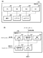
- FIG. 1 is a diagram illustrating an example of the configuration of an image processing system that generates and distributes a virtual viewpoint image.
- the image processing system 100 includes sensor systems 101a to 101n, an image recording device 102, a database server 103, an image generation server 104, a client PC 105, and controllers 106a to 106m.
- sensor systems 101a to 101n an image recording device 102
- database server 103 a database server
- an image generation server 104 a client PC 105
- controllers 106a to 106m controllers 106a to 106m.
- the sensor systems 101a to 101n are installed so as to surround a three-dimensional space that is an area to be imaged such as a stadium.
- One sensor system has at least one camera.
- FIG. 2 shows an installation example of the sensor systems 101a to 101n.
- the field in the stadium and the players and balls in the field are objects (objects), and N sensor systems 101a to 101n are installed so as to surround them.
- Each of the sensor systems 101a to 101n has a camera and a microphone (not shown).
- the cameras of the sensor systems 101a to 101n synchronously capture the same object.
- a group of a plurality of images with different viewpoints obtained by capturing images from different directions with each camera is a multi-viewpoint image.
- each microphone (not shown) synchronizes and collects sound. It should be noted that although the description of the sound is omitted for simplification of the description, it is basically assumed that both the image and the sound are processed.
- the image recording device 102 acquires a multi-viewpoint image, sound, and a time code attached at the time of image capturing from the sensor systems 101a to 101n, and stores the time code in the database server 103.
- the multi-viewpoint image may be subjected to image processing such as foreground / background separation processing, and may be stored in the database server 103 together with the result.
- the controllers 106a to 106m are input devices for each user to operate the virtual cameras 210a to 210m, and for example, a joystick, a tablet, a head mounted display (HMD), etc. are used.
- a virtual viewpoint image is generated in the image generation server 104 according to the virtual viewpoint specified by the user using the controllers 106a to 106m.
- a plurality of controllers 106a to 106m are simultaneously used by a plurality of operators, and different virtual viewpoints are independently set.
- one tablet may be configured to specify a plurality of different virtual viewpoints.
- controller 106 when any one of the controllers 106a to 106m is shown, it is referred to as “controller 106”, and when one of the virtual cameras 210a to 210m is shown, it is referred to as “virtual camera 210”. Notation shall be given.
- the client PC 105 is an information processing device for an operator or the like to provide the image generation server 104 with information necessary for generation and distribution of a virtual viewpoint image.
- the operator uses the user interface described below to specify information such as the number of virtual viewpoint images to be generated, the projection method applied at the time of generation, the output destination (distribution destination) of the generated virtual viewpoint image (hereinafter, “instruction information”). Is created and sent to the image generation server 104.
- the image generation server 104 generates virtual viewpoint images by various projection methods from the multiple viewpoint images acquired from the database server 103 according to the instruction information sent from the client PC 105. At that time, the virtual viewpoint set by the controllers 106a to 106m is used. Then, the image generation server 104 outputs the generated one or more virtual viewpoint images to the designated distribution destinations A to Z.
- distribution destinations include, for example, video sharing sites, SNS, broadcasting centers, public viewing, and the like.
- a video sharing site or SNS both live distribution and on-demand distribution are supported, and the operator specifies a projection method according to the distribution mode.
- the live distribution is a live distribution in real time
- the on-demand distribution is a distribution that allows the user to view the stored data when needed. Viewers, whether live distribution or on-demand distribution, can connect to a video sharing site or SNS using a smartphone or the like and easily view the contents.
- the above is an outline of each element that constitutes the image processing system 100.
- the client PC 105 and the image generation server 104 may be realized by one computer, for example. Further, for example, the client PC 105 and the controller 106 may be integrally configured.
- FIG. 3A shows the hardware configuration of the image generation server 104
- FIG. 3B shows the software configuration of the image generation server 104.
- the hardware configuration will be described, and then the software configuration will be described.
- the image generation server 104 is configured of hardware included in a general information processing apparatus, that is, a CPU 301, a RAM 302, a ROM 303, a HDD 304, a communication I / F 305, an input device 306, and an output device 307.
- the CPU 301 is a processor that uses the RAM 302 as a work memory, executes various programs stored in the ROM 303, and integrally controls each unit of the image generation server 104.
- the functions of the processing modules shown in FIG. 3B are realized by the CPU 301 executing various programs.
- the RAM 302 temporarily stores the program read out from the ROM 303, the calculation result, and the like.
- the ROM 303 holds programs such as OS and data that do not need to be changed.
- the HDD 304 is a large-capacity storage device that stores a multi-viewpoint image read from the database server 103, a generated virtual viewpoint image, and the like, and may be an SSD or the like, for example.
- the communication I / F 305 is compatible with communication standards such as Ethernet and USB, and communicates with the database server 103, the client PC 105, and the controllers 106a to 106m.
- the input device 306 is a keyboard, a mouse or the like for the operator to perform various input operations.
- the output device 307 is a display device such as a monitor that displays information (UI screen or the like) necessary for the operator. When a touch panel display is adopted as the output device 117, it also serves as the input device 116 described above.
- the hardware configuration described above is also included in the client PC 105, for example.
- the image generation server 104 has five processing modules: a main control module 311, a drawing preprocessing module 312, a virtual viewpoint complementing module 313, a drawing module 314, and a distribution module 315.
- a virtual viewpoint image corresponding to one or more specified projection methods among the four types of predetermined projection methods such as the 2D method, 3D method, panoramic method, and 3D panoramic method described above. The description will be given assuming that it is generated. Note that the projection methods that can be specified are not limited to the above four types. As will be described later, the number of virtual viewpoints represented by the viewpoint information used to generate the virtual viewpoint image differs depending on the projection method.
- the main control module 311 is a module that plays a central role in generating a virtual viewpoint image according to the above-described instruction information, and issues various instructions to other processing modules. For example, when the 3D method is designated, the virtual viewpoint set by the controller 106 is not sufficient, and therefore the virtual viewpoint complementing module 313 is instructed to complement the missing virtual viewpoint. Then, the drawing module 314 is instructed to execute the drawing process using the two virtual viewpoints (the virtual viewpoint set by the user by the controller 106 and the virtual viewpoint obtained by the above complement). Then, the drawing processing result (two images corresponding to the two virtual viewpoints) received from the drawing module 314 is subjected to a combining process to generate one virtual viewpoint image by the 3D method.
- the main control module 311 can perform such a series of processes simultaneously in parallel according to the number of generations designated by the instruction information from the client PC 105, and generate and deliver a plurality of virtual viewpoint images.
- the drawing pre-processing module 312 acquires a multi-viewpoint image from the database server 103 by designating a time code at the time of image capturing.
- the multi-viewpoint images are captured by the cameras of the sensor systems 101a to 101n synchronously and stored in the database server 103 by the image recording device 102.
- the drawing preprocessing module 312 also performs processing of generating data (three-dimensional model) representing the three-dimensional shape of the foreground and background used in the drawing processing (rendering) in the drawing module 314 from the multi-viewpoint image.
- This three-dimensional model is generated using a shape estimation method (for example, Visual Hull), and is composed of, for example, a point cloud.
- the three-dimensional model is generated by another device such as the image recording device 102, and the drawing preprocessing module 312 acquires the three-dimensional model generated by another device together with the multi-viewpoint images. But it's okay.
- the virtual viewpoint complementing module 313 acquires viewpoint information (hereinafter, also referred to as “virtual camera parameter”) that specifies the positions and orientations (postures) of the virtual cameras 210a to 210m output by the controllers 106a to 106m, respectively.
- This viewpoint information may include not only the position and orientation of the virtual cameras 210a to 210m but also information such as magnification (zoom), for example.
- the number of virtual viewpoints required to generate one virtual viewpoint image differs depending on the projection method. For example, when the designated projection method is the 2D method, only one virtual viewpoint is sufficient. On the other hand, in the case of the 3D method, another virtual viewpoint having a binocular parallax relationship with the virtual viewpoint specified by the viewpoint information acquired from the controller 106 is required.
- the virtual viewpoint complementing module 313 complements the necessary number of virtual viewpoints according to the projection method specified by the instruction information, based on the virtual viewpoints related to the viewpoint information input from the controller 106. Thus, the insufficient amount of viewpoint information is generated.
- the complement of the virtual viewpoint will be described later.
- the rendering module 314 perspectively projects and renders a three-dimensional model of the foreground or background based on one or more virtual viewpoints specified by the viewpoint information received from the virtual viewpoint complementing module 313. Specifically, a multi-viewpoint image to be used for each point forming the three-dimensional model is selected, an appropriate pixel value in the selected multi-viewpoint image is acquired based on the virtual viewpoint, and color processing is performed. The drawing result is sent to the main control module 313.
- the distribution module 315 transmits the virtual viewpoint image generated as described above to the designated distribution destination.
- the delivery destinations of the plurality of virtual viewpoint images according to the plurality of projection methods may be different delivery destinations, or at least some delivery destinations may be the same. In the case of the present embodiment, it is possible to output one virtual viewpoint image to a plurality of distribution destinations, as described later.
- the virtual viewpoint image distributed by the image generation server 104 may be expressed as “stream”, and the number of distributions may be expressed as “stream number”.
- the image generation server 104 of the present embodiment applies various projection methods from a common multi-viewpoint image to generate one or more virtual viewpoint images, and sends them to one or more distribution destinations. It is characterized by transmitting (multi-stream output). According to such a method, it is possible to efficiently meet the requests of various users. For example, when a 3D system image and a panoramic system image are provided by using a conventional captured image that is not a virtual viewpoint image by the conventional method, the captured image that is required is different. In order to provide a 3D system image that is not a panoramic system, it is necessary to capture images for the right eye and the left eye, that is, two images in which the imaging positions are several cm apart and the imaging directions are almost the same.
- the image generation server 104 of the present embodiment acquires common multiple-viewpoint images that do not depend on the format of the image to be provided, and uses this to generate and provide images of various formats. You can Further, it is possible to provide images in various formats according to the virtual viewpoint arbitrarily designated by the user, which cannot be realized by a normal captured image.
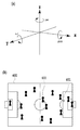
- FIG. 4A shows an orthogonal coordinate system in which the three-dimensional space used in this embodiment is represented by three axes of X axis, Y axis, and Z axis.
- This orthogonal coordinate system is set for each object shown in FIG. 4B, that is, the field 400, the ball 401 existing on the field 400, the player 402, and the like. Further, it may be set in equipment in the stadium such as audience seats and billboards. Specifically, first, the origin (0, 0, 0) is set at the center of the field 400. Then, the X axis is set in the long side direction of the field 400, the Y axis is set in the short side direction of the field 400, and the Z axis is set in the vertical direction with respect to the field 400. The direction of each axis is not limited to these. By using such a coordinate system, the position and orientation of the virtual camera 210 are designated.
- a vertex 501 represents the position of the virtual camera 210
- a vector 502 in the line-of-sight direction starting from the vertex 501 represents the posture of the virtual camera 210.
- the position of the virtual camera is represented by the component (x, y, z) of each axis
- the posture of the virtual camera 210 is represented by a unit vector having the component of each axis as a scalar.
- the vector 502 representing the posture of the virtual camera 210 passes through the center points of the front clip plane 503 and the rear clip plane 504.
- the view frustum of the virtual viewpoint which is the projection range (drawing range) of the three-dimensional model, is the space 505 sandwiched between the front clip plane 503 and the rear clip plane 504.
- FIG. 5B is a diagram for explaining the movement of the virtual viewpoint.
- a dashed arrow 511 represents movement of the virtual viewpoint
- a dashed arrow 512 represents rotation of the moved virtual viewpoint.
- the movement of the virtual viewpoint is represented by components (x, y, z) of each axis, and the rotation of the virtual viewpoint is yaw (Yaw) that is a rotation around the Z axis, pitch (Pitch) that is a rotation around the X axis, It is represented by a roll that is a rotation around the Y axis.
- Such movement and rotation of the virtual viewpoint is used not only in the operation of the virtual camera by the controllers 106a to 106m but also in complementing the virtual viewpoint described below.
- Complementing the virtual viewpoint is to generate an insufficient virtual viewpoint among two or more virtual viewpoints required when the projection method is the 3D method or the panoramic method, based on the virtual viewpoint set by the controller 106. Processing. Thereby, for example, in the case of the 3D method, two virtual viewpoints having a binocular parallax relationship are obtained.
- the virtual viewpoint obtained by this complement is a virtual viewpoint that is different from any of the plurality of virtual viewpoints set by the plurality of controllers 106a to 106m.
- FIG. 5C is a diagram for explaining the complementation of the virtual viewpoint when the 3D method is designated.
- the controller 106 inputs the virtual camera parameters in which the position of the virtual camera is the vertex 501 of the quadrangular pyramid 500 and the orientation thereof is the vector 502 to the virtual viewpoint complementing module 313.
- the above-described movement and rotation are performed on the virtual viewpoint specified by the input virtual camera parameter so that a relationship between the virtual viewpoint and the binocular parallax is obtained.
- a virtual viewpoint is newly generated in which the position of the virtual camera 210 is the vertex 501 'of the quadrangular pyramid 500' and the posture thereof is the vector 502 '.
- the user may specify an appropriate value for realizing the binocular parallax via a UI screen (not shown), or a predetermined value prepared in advance may be applied.
- an appropriate amount of movement and amount of rotation that realizes binocular parallax at a plurality of positions in the target three-dimensional space (for example, positions shifted at predetermined intervals in each of the X, Y, and Z axes) are obtained in advance,
- An LUT is prepared in which the plurality of positions are associated with the obtained movement amount and rotation amount. Then, the movement amount and the rotation amount corresponding to the position of the virtual viewpoint set by the controller 106 may be determined by the interpolation process with reference to the LUT.
- the drawing processing is performed with the virtual viewpoint represented by the quadrangular pyramid 500 for the left eye and the virtual viewpoint represented by the quadrangular pyramid 500 ′ for the right eye, and the images of the respective rendering results are, for example, left and right.
- the images of the respective rendering results are, for example, left and right.
- the virtual viewpoint complementing module 313 complements the necessary number of virtual viewpoints in the specified projection method from the virtual viewpoints set by the arbitrary controller 106.
- the method of complementing the virtual viewpoint differs depending on the projection method.
- the complementing method in the case of the 3D method is as described above, but in the case of the panoramic method, the number of virtual viewpoints necessary to cover the range of up to 360 degrees based on the virtual viewpoint set by the controller 106 is set. It will be complemented. For example, when the number of virtual viewpoints required to cover the entire 360-degree circumference is six, the controller 106 sets the remaining five virtual viewpoints so that the drawing ranges of the respective virtual viewpoints are adjacent. The set reference virtual viewpoint is moved and rotated to be complemented.
- the user may specify an appropriate value via a UI screen (not shown) as in the case of the 3D method, or a predetermined value prepared in advance may be applied. Further, the appropriate movement amount and rotation amount may be obtained using a LUT prepared in advance. Further, another virtual viewpoint may be generated by changing only the direction without changing the position of the reference virtual viewpoint. A panoramic virtual viewpoint image is obtained by synthesizing the images thus generated corresponding to the respective six virtual viewpoints. Further, the 3D panoramic method is a combination of the 3D method and the panoramic method.
- two panoramic images are generated so as to have the binocular parallax.
- 5 out of 11 are obtained by the panoramic method so that the drawing ranges of the respective virtual viewpoints are adjacent to each other, and the remaining 6 are obtained by the 3D method to obtain an appropriate movement amount and rotation amount for the binocular parallax. It can be obtained from the above six items by using.
- a 3D panoramic virtual viewpoint image is obtained.
- the insufficient virtual viewpoints can be obtained by moving and / or rotating the reference virtual viewpoints. Therefore, for example, even when a panoramic virtual viewpoint image is generated, the same number of virtual viewpoints is required. It is not necessary to prepare the number of controllers 106.
- the virtual viewpoints used for generating the respective virtual viewpoint images may be partially common or different.
- the virtual viewpoint image of the 3D method may be generated based on the virtual viewpoint corresponding to the virtual viewpoint image of the 2D method, or the virtual viewpoint corresponding to the virtual viewpoint image of the 2D method and the reference of the virtual viewpoint image of the 3D method. May be different from the virtual viewpoint.
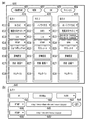
- FIGS. 6A and 6B are diagrams showing an example of a UI screen displayed on a monitor or the like of the client PC 105 for the user to specify the projection method and the delivery destination to create instruction information.
- FIG. 6A shows a main screen 600
- FIG. 6B shows a sub screen for detailed setting. First, the main screen 600 will be described.
- the operator who creates the instruction information first presses the new creation button 601 on the main screen 600.
- the setting list 610 for inputting the information necessary for generating and delivering one virtual viewpoint image is displayed on the main screen 600.
- three setting lists 610, 620 and 630 are displayed, which means that the new creation button 601 has been pressed three times.
- the delete button 602 is used to delete an arbitrary setting list
- the OK button 603 is used when the setting list has been created
- the cancel button 604 is used to stop the setting input operation.
- three virtual viewpoint images are generated by different projection methods and output to four different distribution destinations will be described as an example.
- Each setting list may be displayed as a sub screen different from the main screen 600.
- the OK button 603 may be provided in each of the plurality of setting lists. In this case, it is possible to issue a virtual viewpoint image generation / distribution instruction in units of setting lists.
- Each setting list 610 to 630 includes setting items 611 to 615 for specifying main parameters required to generate each virtual viewpoint image, a detailed setting button 616, a status display column 617, and a thumbnail display column 618, respectively. Exists.
- each element that constitutes the setting list will be described in order.
- the projection method is designated.
- four types of projection methods 2D method, 3D method, panoramic method, and 3D panoramic method, are displayed in a pull-down display, and the operator selects one from them.
- 3D method is specified in the setting item 611 of the setting list 610
- Panorama method is specified in the setting item 611 of the setting list 620
- 3D panorama method is specified in the setting item 611 of the setting list 630. ing.
- the delivery destination is specified.
- the distribution destinations include a video sharing site, an SNS, a broadcasting center of TV stations, and public viewing.
- the content of the delivery destination candidate created in advance may be displayed in a pull-down manner, and the operator may select one from the pull-down display, or the delivery destination address such as a URL may be directly input by the operator.
- the moving picture sharing site is not limited to a specific one, and a plurality of different moving picture sharing sites can be designated. Further, it is possible to specify different URLs or the like even for the same video sharing site.
- the names are displayed so that they can be identified. Here, for the sake of convenience, they can be identified as "video sharing site 1" and "video sharing site 2".
- video sharing site 1 is specified in the setting item 612 of the setting list 610
- SNS1 is specified in the setting item 612 of the setting list 620
- video sharing site 2 is specified in the setting item 612 of the setting list 630. It is specified.
- the delivery format and time code are specified.
- the multi-viewpoint images stored in the database server 103 are attached with the time code, which is time information at the time of image capturing.
- the time code is time information at the time of image capturing.
- the target data can be uniquely identified and acquired.
- on-demand distribution and live distribution are displayed in a pull-down display as the distribution format options, and the operator selects one of them.
- a start time code and an end time code are further designated. Based on such a user instruction, a virtual viewpoint image for on-demand distribution is generated using the multiple viewpoint images identified by the start time code and the end time code.
- the time code at this time is specified in the format such as "2018/08/30 15: 00: 00: 00-2018 / 08/30 15: 30: 00: 20", and the date, time, frame number, etc. Composed of.
- the virtual viewpoint image generated according to the time code and delivered on-demand is used for, for example, replay reproduction of a highlight scene.
- live distribution the processes from the imaging by each camera to the generation and distribution of the virtual viewpoint image are processed in real time. Therefore, it is not practical for the operator to manually specify the time code.
- the designation is ended by selecting the letter notation such as “Live” indicating that the live distribution is performed, and it is not necessary to designate the start and end time codes.
- the image generation server 104 automatically designates the latest time code immediately after recording and sequentially acquires the multi-viewpoint images from the database server 103.
- a plurality of viewpoint images captured by each camera are sequentially acquired, a virtual viewpoint image is generated in real time, and sequentially output to a designated distribution destination. It is also possible to add on-demand distribution as another stream from the middle of live distribution.
- the data format of the stream output from the image generation server 104 is designated.
- This setting item 614 is preferably linked to the setting item 613 described above. That is, when live distribution is designated in the setting item 613 of each setting list, a streaming protocol such as RTMP (Real Time Message Protocol) or HLS (HTTP Live Streaming) is displayed as an option, and Let the operator choose from.
- a video file format such as MP4, AVI, MOV is displayed as an option, and the operator is allowed to select from the options.
- “RTMP” is specified in the setting lists 610 and 620 in which live distribution is specified
- MP4 is specified in the setting list 630 in which on-demand distribution is specified.
- controller identification information for designating which controller 106 is used to generate a virtual viewpoint image.
- the operator selects one from input devices such as a joystick and a tablet displayed as options.
- An identifier is assigned to each of the controllers 106a to 106m, and here, by designating the identifier, which controller is used to generate a virtual viewpoint image is designated.
- an alphabet is added to the type name of the controller such as “joystick A” or “tablet A” to enable identification. Note that the same identifier can be designated for generation of a plurality of virtual viewpoint images.
- tablette A is designated in the setting list 620 and “tablet B” is designated in the setting list 630, but both can be set to “tablet A”, for example.
- two virtual viewpoint images by different projection methods are generated using the virtual viewpoint set on the "tablet A”.
- the type of controller is not limited by the projection method designated by the setting item 611, and different devices of the same model can be designated.
- the detailed setting button 616 is a button for displaying the sub screen for detailed setting shown in FIG. 6B.
- the sub screen for detailed setting will be described later.
- a character string indicating the processing status of the generation and distribution of the virtual viewpoint image (for example, “during distribution”, “completed”, “error”, etc.) is displayed.
- “during distribution” indicates that the virtual viewpoint image is being output to the specified distribution destination
- “completion” indicates that the generation and distribution processing has been completed
- “error” indicates that the virtual viewpoint image has been generated and distributed. Indicates that an error has occurred.
- the contents of the status display are not limited to the above three.
- a thumbnail image of the virtual viewpoint image being processed is displayed in the thumbnail display field 618.
- the operator can intuitively understand whether or not the contents specified by each setting item are as intended, and whether or not they are normally processed.
- a message or the like indicating that the error is occurring is displayed.
- the UI screen shown in FIG. 6A is merely an example, and any UI screen can be used as long as the desired projection method can be specified and one or more virtual viewpoint images can be generated and their distribution destinations can be specified. Such a UI screen may be used.
- an operator may directly input an arbitrary character string, numerical value, or the like, instead of selecting from preset options.
- the resolution of the virtual viewpoint image to be generated is specified.
- FHD Full HD
- 4K 4K
- 8K etc.
- the frame rate of the virtual viewpoint image to be generated is designated.
- 29.97, 30 fps, 59.94 fps, 60 fps, etc. can be designated, and the operator selects one from these displayed as options.
- the encoding method for the virtual viewpoint image to be output is designated.
- H.264. H.264, H.264. 265, HEVC, etc. can be designated, and the operator selects one from these displayed as options.
- an operator may directly input an arbitrary numerical value instead of specifying from the options.
- the setting field 644 the content specified by the setting item 614 (output data format) on the main screen 600 described above is set. For example, when “RTMP” is specified in the setting item 614, the setting field 644 also becomes “RTMP”. Then, in the adjacent input field 645, the URL of the RTMP server which is the output destination is input. If “MP4” is specified in the setting item 614 on the main screen, the setting field 644 also becomes “MP4”. Then, in the adjacent input field 645, the path and API of the file server that is the output destination is input. Further, by pressing the add button 646 next to it, the delivery destination can be added. As a result, one virtual viewpoint image generated according to the setting list can be output to a plurality of different distribution destinations.
- the add button 646 is pressed once, "RTMP" is entered in the setting field 644 'relating to the other delivery destination, and its URL is entered in its input field 645'.
- the setting field 644 of the sub screen 640 and the setting item 614 of the main screen 600 are linked, and when the content of the setting field 644 is changed, the content of the setting item 614 is also changed.
- the output data formats of the delivery destinations to be added do not have to be the same, and it is possible to specify “HLS” instead of “RTMP”, for example.
- the detailed setting items are not limited to the above as long as they are parameters for generating the virtual viewpoint image.
- the operator designates various items relating to the generation and distribution of the virtual viewpoint image, creates the above-mentioned instruction information, and sends it to the image generation server 104.
- a total of three virtual viewpoint images are generated by different projection methods based on virtual viewpoints from different controllers 106 and output to different distribution destinations.
- a common projection method may be designated in the setting item 611 of each setting list, and an identifier of a different controller 106 may be designated in the setting item 615.
- the live distribution and the on-demand distribution are combined, but it is also possible to distribute all the streams live. It is also possible to archive virtual viewpoint images generated with the same settings during live distribution, and to output them as on-demand distribution during live distribution or after completion.
- FIG. 7A is a flowchart showing a rough flow of virtual viewpoint image generation / distribution processing. This series of processing is realized by the CPU 301 executing a predetermined program and operating each processing module shown in FIG.
- step S ⁇ b> 701 the main control module 311 receives the instruction information created for each setting list unit from the client PC 105.
- the drawing preprocessing module 312 is instructed to acquire a multi-viewpoint image.
- the acquisition of the multi-viewpoint images corresponding to the time code specified in each setting list is instructed.
- the drawing preprocessing module 312 that has received the instruction specifies a time code based on the content of the setting item 613 in the setting list, and acquires a multi-viewpoint image from the database server 103.
- each processing module operates under the control of the main control module 311 to generate a designated number of virtual viewpoint images according to the instruction information, and output the virtual viewpoint images to the designated distribution destination.
- a plurality of virtual viewpoint images corresponding to a common time code can be generated as a plurality of virtual viewpoint images of different projection methods.
- the instruction information is composed of a plurality of setting lists
- a series of processes based on each setting list may be executed in parallel or sequentially. Details of the generation and distribution of the virtual viewpoint image in this step will be described with reference to another flow shown in FIG. Since the present embodiment is premised on moving images, the flow shown in FIG. 7B is executed in frame units.
- the main control module 311 identifies the projection method specified in the processing target setting list, and determines the next step. Specifically, if the 2D method has been specified, to S712; if the 3D method has been specified, to S714; if the panoramic method has been specified, to S716, if the 3D panoramic method has been specified Advances to S718, respectively.
- a process of generating a 2D virtual viewpoint image is executed.
- the generated virtual viewpoint image of the 2D method is output to the distribution destination specified in the setting list.
- a process of generating a 3D virtual viewpoint image is executed, and in S715, the 3D virtual viewpoint image is output to the delivery destination specified in the setting list.
- a process of generating a panoramic virtual viewpoint image is executed, and in step S717, the panoramic virtual viewpoint image is output to the distribution destination specified in the setting list.
- FIG. 8A is a flowchart showing details of virtual viewpoint image generation by the 2D method.
- step S801 the virtual viewpoint complementing module 313 acquires virtual camera parameters from the controller 106 corresponding to the identifier specified in the setting list.
- This virtual camera parameter includes at least information that specifies the position and orientation of the virtual camera.
- FIG. 9A shows an example of a virtual viewpoint set for a shoot scene. It is assumed that the virtual camera 210 is set at a position facing the direction of the ball 401 from outside the penalty area, as indicated by a mark 901 in the diagram shown in FIG. 4B, and corresponds to the mark 901. It is assumed that the virtual camera parameters to be acquired have been acquired. It is assumed that the Z-axis of the virtual viewpoint set in the diagram shown in FIG. 9A is fixed at a height that is the line of sight of the player.
- step S ⁇ b> 802 the drawing module 314 uses the three-dimensional model of the foreground or background provided from the drawing preprocessing module 312 to perform drawing processing by perspective projection from the virtual viewpoint represented by the virtual camera parameter acquired in step S ⁇ b> 801.
- the drawing result does not need to be combined and converted, so that the drawing result is output as it is as a virtual viewpoint image for distribution.
- FIG. 9B shows a 2D virtual viewpoint image corresponding to the virtual viewpoint of the mark 901 described above. In this case, a virtual viewpoint image from the player's eyes outside the penalty area can be obtained.
- FIG. 8B is a flowchart showing details of virtual viewpoint image generation by the 3D method.
- the 3D method two virtual viewpoints are used to generate two images having a binocular parallax relationship.
- the virtual viewpoint complementing module 313 acquires the virtual camera parameter from the controller 106 corresponding to the identifier specified in the setting list.
- the virtual camera 210 facing the direction of the ball 401 from the position of the goalkeeper is set as shown by a mark 902, and the virtual camera parameter corresponding to the mark 902 is set. It is assumed to have been acquired.
- the virtual viewpoint complementing module 313 complements another virtual viewpoint for realizing the binocular parallax based on the virtual camera parameter acquired in S811.
- the complementing method at this time is as described above.
- step S813 the drawing module 314 uses the foreground and background three-dimensional models provided from the drawing preprocessing module 312 to perform drawing processing by perspective projection for each of the virtual viewpoint acquired in step S811 and the virtual viewpoint complemented in step S812. To do.
- the main control module 311 arranges the rendering results (two images corresponding to two virtual viewpoints with parallax) in S813 side by side to perform a combining process to generate one 3D virtual viewpoint image. ..
- the format in which two images with binocular parallax are arranged side by side is called the Side by Side format.
- the 3D virtual viewpoint image thus obtained is distributed.
- FIG. 9C shows a 3D virtual viewpoint image corresponding to the virtual viewpoint of the mark 902 described above. In this case, the virtual viewpoint image is the same as that of the goalkeeper. If a headset using a smartphone compatible with 3D display or a head mounted display is attached, the user can stereoscopically view the virtual viewpoint image. In the example of FIG. 9C, the user can experience a powerful scene in which the shot ball is in front of the user, as if he / she became a goalkeeper.
- FIG. 8C is a flowchart showing details of virtual viewpoint image generation by the panoramic method.
- the panoramic method uses more virtual viewpoints than the 3D method in order to cover the entire 360 degrees at the maximum.
- the virtual viewpoint complementing module 313 acquires the virtual camera parameter from the controller 106 corresponding to the identifier specified in the setting list. 9A, it is assumed that the virtual camera 210 is set at a position facing the ball 401 in the penalty area as indicated by a mark 903, and the virtual camera parameter corresponding to the mark 903 is set. Is acquired.
- the virtual viewpoint complementing module 313 complements the number of virtual viewpoints necessary to generate the panoramic image in the panoramic method based on the virtual camera parameters acquired in S821.
- the complementing method at this time is as described above. It should be noted that if the number of virtual viewpoints to be complemented is small, a panoramic image in a range narrower than the entire circumference will be produced accordingly.
- step S823 the drawing module 314 uses the three-dimensional model of the foreground or background provided from the drawing preprocessing module 312 to perform perspective projection for each of the virtual viewpoint acquired in step S821 and the one or more virtual viewpoints complemented in step S822. The drawing process is performed.
- the main control module 311 converts the drawing result in S823 (a plurality of images corresponding to a plurality of virtual viewpoints) into an equirectangular projection, and generates one virtual viewpoint image of the panoramic method.
- the panoramic virtual viewpoint image thus obtained is distributed.
- FIG. 9D shows a panoramic virtual viewpoint image corresponding to the virtual camera 210 of the mark 903 described above.
- the virtual viewpoint image is 360 degrees around the position 903 in the penalty area.
- FIG. 8D is a flowchart showing details of virtual viewpoint image generation by the 3D panoramic method.
- the 3D panoramic method in order to cover the entire circumference of 360 degrees and to realize binocular parallax, twice the number of virtual viewpoints as in the panoramic method is used.
- the virtual viewpoint complementing module 313 acquires the virtual camera parameter from the controller 106 corresponding to the identifier designated in the setting list. Now, as in the case of the panorama method described above, it is assumed that the virtual camera 210 is set at the position indicated by the mark 903 (see FIG. 9A), and the virtual camera parameter corresponding to the mark 903 is acquired. And
- the virtual viewpoint complementing module 313 covers the entire circumference by the 3D panoramic method based on the virtual camera parameters acquired in S831, and complements the number of virtual viewpoints necessary for generating a binocular parallax image.
- the complementing method at this time is as described above.
- step S833 the drawing module 314 draws by perspective projection the virtual viewpoint acquired in step S831 and the plurality of virtual viewpoints complemented in step S832 by using the foreground and background three-dimensional models provided from the drawing preprocessing module 312. Perform processing.
- the main control module 311 divides the drawing result (a plurality of images corresponding to a plurality of virtual viewpoints) in S833 into one for the left eye and one for the right eye, and converts each image group into an equirectangular projection. As a result, one panoramic image is obtained for the left eye and one image for the right eye.
- the main control module 311 arranges the rendering results (two panoramic images with parallax) in S834 one above the other to perform a synthesis process to generate one 3D panoramic virtual viewpoint image.
- the format in which two images with binocular parallax are arranged vertically is called Top and Bottom format.
- the 3D panoramic virtual viewpoint image thus obtained will be distributed.
- FIG. 9E shows a 3D panoramic virtual viewpoint image corresponding to the virtual camera 210 of the mark 903 described above. In this case as well, as in the case of FIG. 9D described above, the image is a 360-degree omnidirectional image around the position 903 in the penalty area, and a virtual viewpoint image with binocular parallax.
- the user can wear the above-described headset or the like to stereoscopically view the virtual viewpoint image including the entire circumference of 360 degrees.
- the user can follow the shooting scene by simply turning the user's head in the desired direction with a sense of realism as if the user were standing in the penalty area.
- the above is the virtual viewpoint image generation processing by each projection method.
- the virtual viewpoint image generation process by each of the above-described projection methods is an example, and the present invention is not limited to the above contents. It suffices that the virtual viewpoint image corresponding to each projection method can be generated, and the processing order, the image format, and the like can be appropriately changed.
- the process of generating and distributing the virtual viewpoint image according to the above-described embodiment may be overloaded depending on the number of generated virtual viewpoint images and the capacity of the multiple viewpoint images.
- a high-resolution multi-viewpoint image such as 4K or 8K
- the capacity of the multi-viewpoint image becomes large, and depending on the number of virtual viewpoint images to be generated, it is difficult for one image generation server 104 to generate them without delay. Can be. In that case, it becomes impossible to fully function as a system, such as simultaneous real-time output in response to a plurality of live distribution requests.
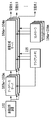
- a distributed configuration as shown in FIG. 10 may be adopted.
- a plurality of image generation servers 104a to 104m and a plurality of database servers 103a to 103m are prepared in advance, and among them, the database server required to correspond to the number of generations designated by the instruction information. And image generation server.
- the image generation servers 104a to 104m are connected to the database servers 103a to 103m on a one-to-one basis. Then, the same multi-viewpoint image is stored in the database servers 103a to 103m by the image recording apparatus 102, and the image generation servers 104a to 104m respectively acquire the multi-viewpoint image. Then, each of the image generation servers 104a to 104m generates one virtual viewpoint image according to the instruction information received from the client PC 105, and outputs it to the designated distribution destination. Since the database servers 103a to 103m all store the same multi-viewpoint image, they may be configured as cache servers. Note that, also in the example of FIG. 10, the single client PC 105 is used to create the instruction information for each of the image generation servers 104a to 104m, but a plurality of units may be used.
- a dedicated management device for controlling the image generation servers 104a to 104m and the database servers 103a to 103m is provided, and the process of allocating to each image generation server 104 is executed instead of the determination process of S711 in the flow of FIG. 7B. It may be configured to.
- the function of the management device may be provided in the tablets as the controllers 106a to 106m. Distribution of the generated virtual viewpoint image may be performed by each of the image generation servers 104a to 104m, or may be configured such that the management device performs the distribution process instead.
- some of the plurality of image generation servers 104a to 104m may generate / deliver a plurality of virtual viewpoint images.
- the management device determines the number of image generation servers to be used based on the format (projection method) of virtual viewpoint images to be generated and distributed or the number of virtual viewpoint images. Then, the management device controls the duplication and output of the multi-viewpoint image by the image recording device 102 so that the same multi-viewpoint image is stored in the same number of database servers as the number of image generation servers used.
- the plurality of virtual viewpoint images generated by the plurality of image generation servers may be output to different distribution destinations.
- the number of database servers and the number of image generation servers to be used can be flexibly set according to the number of generated virtual viewpoint images even when the multi-viewpoint images have a high resolution and a large capacity. it can. By adopting such a distributed configuration, it is possible to cope with a case where a high-quality virtual viewpoint image is live-distributed to many distribution destinations.
- the projection method can be freely selected.
- the virtual viewpoints corresponding to the respective virtual viewpoint images can be set independently. This makes it possible to generate and deliver various types of virtual viewpoint images viewed from various viewpoints in a three-dimensional space of an imaged scene. For example, for a soccer match at a stadium, a 2D image of a virtual viewpoint that follows the ball is delivered to a broadcasting center of a TV station while a 3D image of a virtual viewpoint from the viewpoint of a player such as a goalkeeper is delivered to a movie theater. Etc. can be simultaneously distributed to public viewing such as.
- a panorama format or 3D panorama format image in which a high-line scene such as a shot scene can be viewed 360 degrees freely within the penalty area to a video distribution site or SNS.
- the application target of the present embodiment is not limited to sports scenes, but can be widely applied to, for example, concerts of famous artists, and it is possible to provide users with various new viewing experiences using virtual viewpoint images. ..
- the present invention supplies a program that implements one or more functions of the above-described embodiments to a system or apparatus via a network or a storage medium, and one or more processors in a computer of the system or apparatus read and execute the program. It can also be realized by the processing. It can also be realized by a circuit (for example, ASIC) that realizes one or more functions.
- a circuit for example, ASIC
Landscapes
- Engineering & Computer Science (AREA)
- Theoretical Computer Science (AREA)
- Physics & Mathematics (AREA)
- Multimedia (AREA)
- Signal Processing (AREA)
- General Physics & Mathematics (AREA)
- General Engineering & Computer Science (AREA)
- Human Computer Interaction (AREA)
- Computer Graphics (AREA)
- Computing Systems (AREA)
- Geometry (AREA)
- Computer Hardware Design (AREA)
- Software Systems (AREA)
- Processing Or Creating Images (AREA)
- Image Generation (AREA)
- Testing, Inspecting, Measuring Of Stereoscopic Televisions And Televisions (AREA)
- User Interface Of Digital Computer (AREA)
Abstract
情報処理システムは、対象領域をそれぞれ異なる方向から撮像する複数の撮像装置による撮像に基づく複数の画像を取得する画像取得手段と、仮想視点の位置及び向きを示す視点情報を取得する視点取得手段と、複数の画像形式に応じた複数の仮想視点コンテンツを、前記画像取得手段により取得された共通の前記複数の画像と前記視点取得手段により取得された視点情報とに基づいて生成する生成手段と、を有し、前記複数の画像形式は、前記仮想視点コンテンツの生成に用いられる前記視点情報が表す仮想視点の数がそれぞれ異なる画像形式である、ことを特徴とする。
Description
本発明は仮想視点画像の生成及び配信に関する。
複数台の実カメラで撮像した映像を用いて、3次元空間内に仮想的に配置した実際には存在しないカメラ(仮想カメラ)からの映像を再現する技術として、仮想視点画像生成技術がある。
仮想視点画像は、例えば、サッカー等のスポーツにおけるハイライトシーンなどを様々な角度から閲覧可能とし、実際のカメラで撮像した通常画像と比較して、ユーザへ高臨場感を与えることが出来るという特徴がある。特許文献1には、複数のユーザそれぞれにより指定された仮想視点に応じた複数の仮想視点画像を生成し、それを複数のユーザ間で共有する技術が記載されている。
上記特許文献1に記載の技術において生成・配信される複数の仮想視点画像は、仮想視点が異なるだけですべて共通の形式(投影方式)による仮想視点画像である。しかしながら、近年はより多様な形式の画像コンテンツを提供することが求められている。例えばカメラにより撮像された撮像画像を配信する際の画像の形式として、一般的な二次元方式(以降、「2D方式」と表記)に限らず、視差のある2枚の画像を用いて立体視を実現する三次元方式(以降、「3D方式」と表記)がある。その他にも、最大360度の範囲で視線方向を変更可能なパノラマ方式や、パノラマ方式で得た2枚の画像を用いて立体視を実現する3Dパノラマ方式等がある。通常の撮像画像だけではなく、視点を任意に指定可能な仮想視点画像についても上述したような多様な形式の画像コンテンツをユーザに提供することができれば、目新しい視聴体験が可能となって、ユーザの満足度を向上させることができる。
本発明は上記の課題に鑑みなされたもので、複数の撮像装置により撮像することで得られた画像に基づいて、複数の異なる形式の仮想視点コンテンツをユーザに提供できるようにすることを目的とする。
本発明に係る情報処理システムは、対象領域をそれぞれ異なる方向から撮像する複数の撮像装置による撮像に基づく複数の画像を取得する画像取得手段と、仮想視点の位置及び向きを示す視点情報を取得する視点取得手段と、複数の画像形式に応じた複数の仮想視点コンテンツを、前記画像取得手段により取得された共通の前記複数の画像と前記視点取得手段により取得された視点情報とに基づいて生成する生成手段と、を有し、前記複数の画像形式は、前記仮想視点コンテンツの生成に用いられる前記視点情報が表す仮想視点の数がそれぞれ異なる画像形式である、ことを特徴とする。
本発明によれば、複数の撮像装置により撮像することで得られた画像に基づいて、複数の異なる形式の仮想視点コンテンツをユーザに提供することができる。
本発明の更なる特徴は、添付の図面を参照して行う以下の実施形態の説明より明らかになる。
以下、本発明の実施形態について図面を参照し説明する。なお、説明する実施形態は、本発明を具体的に実施した場合の一例を示すものであり、これに限るものではない。
本実施形態では、撮像対象となる3次元空間を囲むように複数の撮像装置(カメラ)を配置し、当該複数のカメラで撮像して得られた画像に基づき、画像形式の異なる複数の仮想視点コンテンツを生成・配信する態様を説明する。本実施形態における画像形式は、仮想視点コンテンツをユーザに提供するために用いられる画像形式であり、以下では投影方式とも表記する。また、仮想視点コンテンツは、エンドユーザ及び/又は選任のオペレータ等が仮想視点に対応するカメラ(仮想カメラ)の位置及び姿勢(向き)を操作することによって変化する画像のコンテンツであり、自由視点画像や任意視点画像などとも呼ばれる。以下では仮想視点コンテンツを仮想視点画像とも表記する。仮想視点画像は、動画であっても、静止画であってもよいが、本実施形態では動画の場合を例に説明を行うものとする。
(システム構成)
図1は、仮想視点画像を生成・配信する画像処理システムの構成の一例を示す図である。画像処理システム100は、センサシステム101a~101n、画像記録装置102、データベースサーバ103、画像生成サーバ104、クライアントPC105、コントローラ106a~106mで構成される。以下、画像処理システム100を構成する各部について説明する。
図1は、仮想視点画像を生成・配信する画像処理システムの構成の一例を示す図である。画像処理システム100は、センサシステム101a~101n、画像記録装置102、データベースサーバ103、画像生成サーバ104、クライアントPC105、コントローラ106a~106mで構成される。以下、画像処理システム100を構成する各部について説明する。
センサシステム101a~101nは、スタジアムなど撮像対象の領域となる3次元空間を囲む様に設置される。1台のセンサシステムは少なくとも1台のカメラを有する。図2にセンサシステム101a~101nの設置例を示す。図2の例は、スタジアム内のフィールドとその中にいる選手やボールを被写体(オブジェクト)とし、それらを囲む様にN台のセンサシステム101a~101nを設置したものである。センサシステム101a~101nは、それぞれカメラとマイク(不図示)を有する。各センサシステム101a~101nが有する各カメラは同期して同一のオブジェクトを撮像する。各カメラでそれぞれ異なる方向から撮像して得られた視点の異なる複数の画像のまとまりが複数視点画像である。また、不図示の各マイクは同期し音声を集音する。なお、説明の簡略化のため音声についての記載を省略するが、基本的に画像と音声は共に処理されるものとする。
画像記録装置102は、センサシステム101a~101nから、複数視点画像と、音声と、撮像時に付されるタイムコードを取得し、データベースサーバ103へ保存する。複数視点画像については、例えば前景・背景分離処理などの画像処理を施し、その結果と合わせてデータベースサーバ103へ保存してもよい。
コントローラ106a~106mは、仮想カメラ210a~210mを各ユーザが操作するための入力デバイスであり、例えば、ジョイスティック、タブレット、ヘッドマウントディスプレイ(HMD)等が使用される。コントローラ106a~106mを用いてユーザが指定した仮想視点に従って、画像生成サーバ104において仮想視点画像が生成される。本実施形態では、複数のコントローラ106a~106mを複数のオペレータが同時に使用し、それぞれ独立して異なる仮想視点を設定する構成としている。しかし、例えば1つのタブレットで、複数の異なる仮想視点を指定できるような構成でも構わない。なお、以下の説明では、コントローラ106a~106mのうち任意の1つを示す場合は「コントローラ106」と表記し、仮想カメラ210a~210mのうち任意の1つを示す場合は「仮想カメラ210」と表記するものとする。
クライアントPC105は、オペレータ等が、仮想視点画像の生成や配信に必要な情報を、画像生成サーバ104に提供するための情報処理装置である。オペレータは、後述のユーザインタフェースを使用して、仮想視点画像の生成数及び生成時に適用する投影方式、生成した仮想視点画像の出力先(配信先)などを指定した情報(以下、「指示情報」と呼ぶ。)を作成し、画像生成サーバ104に送る。
画像生成サーバ104は、クライアントPC105から送られてくる指示情報に従い、データベースサーバ103から取得した複数視点画像から、様々な投影方式による仮想視点画像を生成する。その際、コントローラ106a~106mにて設定された仮想視点を用いる。そして、画像生成サーバ104は、生成した1つ以上の仮想視点画像を、指定された配信先A~Zへ出力する。配信先の例としては、例えば、動画共有サイト、SNS、放送センター、パブリックビューイング等がある。ここで、動画共有サイトやSNSの場合は、ライブ配信とオンデマンド配信の両方の配信形式に対応しており、オペレータは配信態様に応じた投影方式を指定することになる。ライブ配信とはリアルタイムに生中継される配信であり、オンデマンド配信とは蓄積されたデータをユーザが必要な時に視聴可能とする配信である。視聴者は、ライブ配信でもオンデマンド配信であっても、スマートフォン等を使用して動画共有サイトやSNSへ接続し、簡単に視聴することができる。
以上が、画像処理システム100を構成する各要素の概要である。なお、上記のシステム構成は一例であり、例えばクライアントPC105と画像生成サーバ104とが1つのコンピュータで実現されていてもよい。また例えば、クライアントPC105とコントローラ106とが一体となって構成されていてもよい。
(画像生成サーバの構成・機能)
続いて、画像生成サーバ104の構成・機能について詳しく説明する。図3(a)は画像生成サーバ104のハードウェア構成を示し、同(b)は画像生成サーバ104のソフトウェア構成を示す。まず、ハードウェア構成を説明し、次にソフトウェア構成を説明する。
続いて、画像生成サーバ104の構成・機能について詳しく説明する。図3(a)は画像生成サーバ104のハードウェア構成を示し、同(b)は画像生成サーバ104のソフトウェア構成を示す。まず、ハードウェア構成を説明し、次にソフトウェア構成を説明する。
画像生成サーバ104は、一般的な情報処理装置が有するハードウェア、すなわち、CPU301、RAM302、ROM303、HDD304、通信I/F305、入力デバイス306、出力デバイス307で構成される。CPU301は、RAM302をワークメモリとして、ROM303に格納された各種プログラムを実行し、画像生成サーバ104の各部を統括的に制御するプロセッサである。CPU301が、各種プログラムを実行することによって、図3(b)に示す各処理モジュールの機能が実現される。RAM302は、ROM303から読み出されたプログラムや演算結果などを一時的に記憶する。ROM303は、変更を必要としないOSなどのプログラムやデータを保持する。HDD304は、データベースサーバ103から読み出した複数視点画像や、生成した仮想視点画像などを格納する大容量記憶装置であり、例えばSSDなどでもよい。通信I/F305は、EthernetやUSBなどの通信規格に対応し、データベースサーバ103やクライアントPC105やコントローラ106a~106mとの通信を行う。入力デバイス306は、オペレータが各種入力操作を行うためのキーボードやマウスなどである。出力デバイス307は、オペレータに必要な情報(UI画面等)を表示するモニタ等の表示デバイスである。出力デバイス117として例えばタッチパネルディスプレイを採用した場合は、上述の入力デバイス116を兼ねることになる。なお、上述したハードウェア構成を、例えばクライアントPC105も備えている。
続いて、図3(b)を参照しつつ、画像生成サーバ104の主要なソフトウェア構成を説明する。画像生成サーバ104は、主制御モジュール311、描画前処理モジュール312と、仮想視点補完モジュール313と、描画モジュール314と、配信モジュール315の5つの処理モジュールを有する。本実施形態の画像生成サーバ104では、前述した2D方式、3D方式、パノラマ方式、3Dパノラマ方式の4種類の所定の投影方式のうち、指定された1以上の投影方式に応じた仮想視点画像を生成するものとして説明を行う。なお、指定可能な投影方式は上記4種類に限定されるものではない。後述するように、仮想視点画像の生成に用いられる視点情報が表す仮想視点の数は、投影方式によって異なる。
主制御モジュール311は、前述の指示情報に従って仮想視点画像を生成する際に中心的な役割を担うモジュールであり、他の処理モジュールに対して各種指示を行う。例えば3D方式が指定された場合、コントローラ106にて設定された仮想視点だけでは足りないので、当該足りない分の仮想視点の補完を仮想視点補完モジュール313に指示する。そして、描画モジュール314に対し、2つの仮想視点(コントローラ106でユーザが設定した仮想視点と上記補完によって得られた仮想視点)を用いた描画処理の実行を指示する。そして、描画モジュール314から受け取った描画処理結果(2つの仮想視点に対応した2枚の画像)に対し合成処理を行って、3D方式による1枚の仮想視点画像を生成する。主制御モジュール311は、この様な一連の処理を、クライアントPC105からの指示情報で指定された生成数に応じて同時並行的に行い、複数の仮想視点画像を生成・配信することができる。
描画前処理モジュール312は、データベースサーバ103から、撮像時のタイムコードを指定して複数視点画像を取得する。この複数視点画像は、センサシステム101a~101nの各カメラによって同期撮像され、画像記録装置102によってデータベースサーバ103へ保存されたものである。また、描画前処理モジュール312は、描画モジュール314における描画処理(レンダリング)で用いる前景や背景の三次元形状を表すデータ(三次元モデル)を複数視点画像から生成する処理も行う。この三次元モデルは、形状推定法(例えばVisual Hull等)を用いて生成され、例えば点群で構成される。なお、三次元モデルの生成を例えば画像記録装置102など他の装置で行なうようにし、描画前処理モジュール312は他の装置で生成された三次元モデルを複数視点画像と合わせて取得するような構成でもよい。
仮想視点補完モジュール313は、コントローラ106a~106mそれぞれが出力する仮想カメラ210a~210mの位置と向き(姿勢)を特定する視点情報(以下、「仮想カメラパラメータ」とも表記)を取得する。この視点情報には、仮想カメラ210a~210mの位置及び姿勢だけでなく、例えば倍率(ズーム)などの情報を含んでもよい。1つの仮想視点画像の生成に必要な仮想視点の数はその投影方式よって異なる。例えば、指定された投影方式が2D方式の場合は1つの仮想視点のみで足りる。これに対し3D方式の場合は、コントローラ106から取得した視点情報で特定される仮想視点と両眼視差の関係となるもう1つ別の仮想視点が必要となる。そこで、仮想視点補完モジュール313は、指示情報で指定された投影方式に応じて必要な数の仮想視点を、コントローラ106から入力された視点情報に係る仮想視点を基に補完する。こうして足りない分の視点情報が生成される。この仮想視点の補完については後述する。
描画モジュール314は、仮想視点補完モジュール313から受け取った視点情報で特定される1つ又は複数の仮想視点に基づき、前景や背景の三次元モデルを透視投影して描画する。具体的には、三次元モデルを構成する点毎に使用する複数視点画像を選択し、当該選択した複数視点画像における適切な画素値を仮想視点に基づき取得して、色付けする処理を行う。描画結果は、主制御モジュール313に送られる。
配信モジュール315は、上述のようにして生成された仮想視点画像を、指定された配信先へ送信する。複数の投影方式に応じた複数の仮想視点画像の配信先は、それぞれ異なる配信先であってもよいし、少なくとも一部の配信先が同じであってもよい。本実施形態の場合は、後述のとおり、1つの仮想視点画像を複数の配信先へ出力することも可能である。本明細書では、画像生成サーバ104が配信する仮想視点画像を「ストリーム」、配信数を「ストリーム数」と表現することもある。
以上のとおり、本実施形態の画像生成サーバ104は、共通の複数視点画像から様々な投影方式を適用して1つ又は複数の仮想視点画像を生成し、それらを1つ又は複数の配信先へ送信(マルチストリーム出力)する点を特徴とする。このような方法によれば、様々なユーザの要求に効率的に応えることできる。例えば、従来の方法により、仮想視点画像でない通常の撮像画像を用いて3D方式の画像とパノラマ方式の画像を提供する場合、それぞれ必要となる撮像画像が異なる。パノラマ方式でない3D方式の画像を提供するためには、右目用と左目用の撮像画像、すなわち撮像位置が数cm異なり撮像方向がほぼ同一の2枚の画像が必要となる。一方、360°のパノラマ画像を提供するためには、撮像方向がそれぞれ異なる多数の撮像画像か、又は超広角(魚眼)の撮像画像が必要となる。したがって、複数の異なる形式の画像をユーザに提供するためには、その形式の数に応じた撮像の手間が必要であった。これに対し、本実施形態の画像生成サーバ104は、提供すべき画像の形式に依らない共通の複数視点画像を取得しておき、これを用いて様々な形式の画像を生成して提供することができる。さらに、通常の撮像画像では実現不可能な、ユーザにより任意に指定された仮想視点に応じた様々な形式の画像を提供することができる。
(仮想視点の設定)
続いて、スタジアムでのサッカーの試合を撮像シーンとした場合を例に、オペレータが設定する仮想視点について説明する。まず、仮想視点を設定する際の基準となる、撮像対象の3次元空間を表す座標系について説明する。
続いて、スタジアムでのサッカーの試合を撮像シーンとした場合を例に、オペレータが設定する仮想視点について説明する。まず、仮想視点を設定する際の基準となる、撮像対象の3次元空間を表す座標系について説明する。
図4(a)は、本実施形態で用いる、3次元空間をX軸・Y軸・Z軸の3軸で表した直交座標系を示している。この直交座標系を、図4(b)に示す各オブジェクト、すなわち、フィールド400、その上に存在するボール401、選手402等に設定する。さらに、観客席や看板などのスタジアム内の設備に設定してもよい。具体的には、まず、原点(0、0、0)をフィールド400の中心へ設定する。そして、X軸をフィールド400の長辺方向へ、Y軸をフィールド400の短辺方向へ、Z軸をフィールド400に対して鉛直方向へ設定する。なお、各軸の方向は、これらに限定されない。この様な座標系を使用し、仮想カメラ210の位置と姿勢が指定される。
図5(a)に示す四角錐500において、頂点501が仮想カメラ210の位置を表し、頂点501を起点とする視線方向のベクトル502が仮想カメラ210の姿勢を表す。仮想カメラの位置は、各軸の成分(x,y,z)で表現され、仮想カメラ210の姿勢は、各軸の成分をスカラーとする単位ベクトルで表現される。仮想カメラ210の姿勢を表すベクトル502は、前方クリップ面503と後方クリップ面504の中心点を通るものとする。三次元モデルの投影範囲(描画範囲)となる仮想視点の視錐台は、前方クリップ面503と後方クリップ面504に挟まれた空間505である。次に、仮想視点の移動(仮想カメラ210の位置の変更)と回転(仮想カメラ210の姿勢の変更)について説明する。
仮想視点は、三次元座標で表現された空間内において、移動及び回転させることができる。図5(b)は、仮想視点の移動を説明する図である。図5(b)において、破線の矢印511が仮想視点の移動を表し、破線の矢印512が当該移動した仮想視点の回転を表している。仮想視点の移動は各軸の成分(x、y、z)で表現され、仮想視点の回転は、Z軸回りの回転であるヨー(Yaw)、X軸回りの回転であるピッチ(Pitch)、Y軸回りの回転であるロール(Roll)で表現される。このような仮想視点の移動と回転は、コントローラ106a~106mでの仮想カメラの操縦において使用される他、次に説明する仮想視点の補完にも使用される。
(仮想視点の補完)
仮想視点の補完とは、投影方式が3D方式やパノラマ方式である場合に必要な2以上の仮想視点のうち、足りない分の仮想視点を、コントローラ106にて設定された仮想視点に基づき生成する処理である。これにより、例えば3D方式の場合には、両眼視差の関係にある2つの仮想視点を得る。この補完によって得られる仮想視点は、複数のコントローラ106a~106mによって設定される複数の仮想視点のいずれとも異なる仮想視点である。
仮想視点の補完とは、投影方式が3D方式やパノラマ方式である場合に必要な2以上の仮想視点のうち、足りない分の仮想視点を、コントローラ106にて設定された仮想視点に基づき生成する処理である。これにより、例えば3D方式の場合には、両眼視差の関係にある2つの仮想視点を得る。この補完によって得られる仮想視点は、複数のコントローラ106a~106mによって設定される複数の仮想視点のいずれとも異なる仮想視点である。
図5(c)は、3D方式が指定された場合における、仮想視点の補完を説明する図である。いま、コントローラ106によって、仮想カメラの位置を四角錐500の頂点501、その姿勢をベクトル502とする仮想カメラパラメータが、仮想視点補完モジュール313に入力されたものとする。3D方式の場合、入力仮想カメラパラメータで特定される仮想視点に対し、前述の移動と回転(仮想視点の位置及び向きの変更)を行って、当該仮想視点と両眼視差の関係となるような別の仮想視点を生成する。すなわち、仮想カメラ210の位置を四角錐500’の頂点501’その姿勢をベクトル502’とする仮想視点が新たに生成される。この際の移動量と回転量は、ユーザが不図示のUI画面を介して両眼視差を実現する適切な値を指定してもよいし、予め用意した所定値を適用してもよい。或いは、対象3次元空間内の複数の位置(例えばX、Y、Zの各軸において所定間隔でずらした位置)における両眼視差を実現する適切な移動量と回転量を事前に求めておき、当該複数の位置と求めた移動量及び回転量とを対応付けたLUTを用意しておく。そして、コントローラ106で設定された仮想視点の位置に対応する移動量と回転量を、当該LUTを参照して補間処理によって決定してもよい。こうして得られた2つの仮想視点のうち、四角錐500が表す仮想視点を左目用、四角錐500’が表す仮想視点を右目用とした描画処理がなされ、それぞれの描画結果の画像を例えば左右に並べて合成することで3D方式の1枚の仮想視点画像が得られる。
このように仮想視点補完モジュール313は、任意のコントローラ106にて設定された仮想視点から、指定された投影方式において必要な数の仮想視点を補完する。仮想視点の補完方法は投影方式毎に異なる。3D方式の場合の補完方法は上述のとおりであるが、パノラマ方式の場合は、コントローラ106にて設定された仮想視点を基準に最大360度の範囲を網羅するために必要な数の仮想視点を補完することになる。例えば、360度全周囲を網羅するために必要な仮想視点の数が6つであった場合は、残り5つ分の仮想視点を、各仮想視点の描画範囲が隣接する様にコントローラ106にて設定された基準の仮想視点を移動及び回転させて補完する。この際の移動量と回転量も、3D方式の場合と同様、ユーザが不図示のUI画面を介して適切な値を指定してもよいし、予め用意した所定値を適用してもよい。また、予め用意したLUTを用いて適切な移動量と回転量を求めてもよい。また、基準となる仮想視点の位置を変更せずに向きのみを変更することで、他の仮想視点を生成してもよい。こうして生成された6つの仮想視点それぞれに対応する画像を合成することで、パノラマ方式の仮想視点画像が得られる。また、3Dパノラマ方式は、3D方式とパノラマ方式の組み合わせとなる。つまり、パノラマ画像の両眼視差に基づく立体視を実現するために、両眼視差となる様に、上記パノラマ方式の画像を2つ生成することになる。例えば、360度の全周囲を網羅するために6つの仮想視点を使用する場合であれば、全部で6×2=12の仮想視点が必要となる。よって、コントローラ106にて設定された仮想視点に基づき、残り11個分の仮想視点を補完する。この際、11個の内5つはパノラマ方式の手法で各仮想視点の描画範囲が隣接する様に求め、残りの6つは3D方式の手法で両眼視差に適切な移動量と回転量を用いて先の6つから求めればよい。こうして生成された12個の仮想視点それぞれに対応する画像を合成することで、3Dパノラマ方式の仮想視点画像が得られる。
この様に、各投影方式に応じた仮想視点の補完を自由に行えるのは、複数のカメラによってオブジェクトをあらゆる方向から撮像した複数視点画像が得られているためである。スタジアムのフィールドといった広い範囲に拡がるオブジェクトを対象とした場合であっても、対象3次元空間内の任意の位置に任意の姿勢で設定された仮想カメラの情報を基に、指定された投影方式において要求される別の仮想視点を補完することができる。このように、足りない分の仮想視点を基準の仮想視点の移動及び/又は回転によって得ることができるので、例えばパノラマ方式の仮想視点画像を生成する場合でも、それに要求される仮想視点数と同じ数のコントローラ106を用意しなくても済む。なお、複数の投影方式に応じた複数の仮想視点画像が生成される場合に、それぞれの仮想視点画像の生成に用いられる仮想視点は一部が共通していてもよいし、それぞれ異なっていてもよい。例えば、2D方式の仮想視点画像に対応する仮想視点を基準として3D方式の仮想視点画像が生成されてもよいし、2D方式の仮想視点画像に対応する仮想視点と3D方式の仮想視点画像の基準となる仮想視点とが異なっていてもよい。
(投影方式及び配信先の指定)
次に、クライアンPC105における、仮想視点画像の生成・配信を画像生成サーバ104に対し指示するためのユーザインタフェース(UI)について説明する。図6(a)及び(b)は、クライアントPC105のモニタ等に表示される、ユーザが投影方式や配信先を指定して指示情報を作成するためのUI画面の一例を示す図である。図6(a)がメイン画面600、同(b)が詳細設定のためのサブ画面を示している。まず、メイン画面600から説明する。
次に、クライアンPC105における、仮想視点画像の生成・配信を画像生成サーバ104に対し指示するためのユーザインタフェース(UI)について説明する。図6(a)及び(b)は、クライアントPC105のモニタ等に表示される、ユーザが投影方式や配信先を指定して指示情報を作成するためのUI画面の一例を示す図である。図6(a)がメイン画面600、同(b)が詳細設定のためのサブ画面を示している。まず、メイン画面600から説明する。
<メイン画面>
指示情報を作成するオペレータは、まず、メイン画面600において、新規作成ボタン601を押下する。これにより、1つの仮想視点画像の生成及び配信に必要な情報を入力するための設定リスト610がメイン画面600上に表示される。図6(a)のメイン画面600には、3つの設定リスト610、620及び630が表示されており、これは、新規作成ボタン601が3回押下されたことを意味している。削除ボタン602は任意の設定リストを削除する際に使用し、OKボタン603は設定リストの作成が完了した際に使用し、キャンセルボタン604は設定の入力操作をやめる際に使用する。ここでは一例として、3つの仮想視点画像をそれぞれ異なる投影方式にて生成し、それらを4つの異なる配信先へ出力する場合を例に説明を行うものとする。
指示情報を作成するオペレータは、まず、メイン画面600において、新規作成ボタン601を押下する。これにより、1つの仮想視点画像の生成及び配信に必要な情報を入力するための設定リスト610がメイン画面600上に表示される。図6(a)のメイン画面600には、3つの設定リスト610、620及び630が表示されており、これは、新規作成ボタン601が3回押下されたことを意味している。削除ボタン602は任意の設定リストを削除する際に使用し、OKボタン603は設定リストの作成が完了した際に使用し、キャンセルボタン604は設定の入力操作をやめる際に使用する。ここでは一例として、3つの仮想視点画像をそれぞれ異なる投影方式にて生成し、それらを4つの異なる配信先へ出力する場合を例に説明を行うものとする。
すべての設定リストについての設定が完了し、オペレータがOKボタン603を押下すると、仮想視点画像の生成や配信の詳細を指定した指示情報が、画像生成サーバ104に送信される。なお、各設定リストをメイン画面600とは別のサブ画面として表示してもよい。また、OKボタン603は、複数の設定リストのそれぞれに設けられていてもよい。この場合、設定リスト単位で仮想視点画像の生成・配信指示を行うことができる。各設定リスト610~630には、各仮想視点画像の生成に要求される主要パラメータを指定するための設定項目611~615、詳細設定用ボタン616、状態表示欄617、及びサムネイル表示欄618がそれぞれ存在する。以下、設定リストを構成する各要素について順に説明する。
設定項目611においては、投影方式を指定する。本実施形態では、2D方式、3D方式、パノラマ方式、3Dパノラマ方式の4種類の投影方式がプルダウン表示され、その中からオペレータは1つを選択することになる。いま、設定リスト610の設定項目611では「3D方式」が指定され、設定リスト620の設定項目611では「パノラマ方式」が指定され、設定リスト630の設定項目611では「3Dパノラマ方式」が指定されている。
設定項目612においては、配信先を指定する。前述のとおり配信先としては、動画共有サイト、SNS、TV局の放送センター、パブリックビューイング等がある。予め作成した配信先候補の内容をプルダウン表示し、その中からオペレータに1つを選択させる構成でもよいし、URL等の配信先アドレスをオペレータが直接入力できるように構成してもよい。また、例えば動画共有サイトは特定の1つに限定されず、複数の異なる動画共有サイトを指定可能である。また、同じ動画共有サイトであっても、異なるURL等を指定することも可能である。その際には、それぞれが識別できるような名称を用いて表示を行なう。ここでは、便宜上、「動画共有サイト1」、「動画共有サイト2」として識別可能にしている。なお、SNSやパブリックビューイングなど他の配信先の場合も同様である。いま、設定リスト610の設定項目612では「動画共有サイト1」が指定され、設定リスト620の設定項目612では「SNS1」が指定され、設定リスト630の設定項目612では「動画共有サイト2」が指定されている。
設定項目613においては、配信形式とタイムコードを指定する。前述のとおり、データベースサーバ103に格納されている複数視点画像には撮像時の時間情報であるタイムコードが付されている。このタイムコードを指定してデータベースサーバ103に対し複数視点画像を要求することで、対象のデータを一意に識別して取得することができる。本実施形態では、まず、配信形式の選択肢として、オンデマンド配信とライブ配信がプルダウン表示され、その中からオペレータは1つを選択する。そして、オンデマンド配信の場合はさらに、開始タイムコードと終了タイムコードを指定する。こうしたユーザ指示に基づき、開始タイムコードと終了タイムコードとで識別される複数視点画像を用いてオンデマンド配信用の仮想視点画像が生成される。この際のタイムコードは、例えば「2018/08/30 15:00:00:00-2018/08/30 15:30:00:20」といったフォーマットで指定され、年月日、時間、フレーム番号等から構成される。タイムコードに従って生成されオンデマンド配信される仮想視点画像は、例えばハイライトシーンのリプレイ再生等の用途に供される。一方、ライブ配信の場合は、各カメラによる撮像から仮想視点画像の生成及び配信までをリアルタイムで処理することになる。このため、オペレータが手動でタイムコードを指定する方法は現実的ではない。そこでライブ配信が選択された場合は、「Live」といったライブ配信である旨の文字表記の選択で指定終了となり、開始及び終了のタイムコードの指定は不要としている。ライブ配信が指定された場合、画像生成サーバ104は記録直後の最新のタイムコードを自動で順次指定してデータベースサーバ103から複数視点画像を取得する。ライブ配信の場合は、各カメラで撮像された複数視点画像が順次取得されてリアルタイムに仮想視点画像が生成され、指定された配信先に順次出力される。なお、ライブ配信中に途中から、別ストリームでオンデマンド配信を追加することもできる。
設定項目614においては、画像生成サーバ104から出力されるストリームのデータ形式、具体的には、配信プロトコルの種類やビデオファイルフォーマットの種類を指定する。この設定項目614は、上述の設定項目613とリンクさせるのが望ましい。すなわち、各設定リストの設定項目613にて、ライブ配信が指定された場合には、例えばRTMP(Real Time Message Protocol)やHLS(HTTP Live Streaming)といったストリーミング用のプロトコルを選択肢として表示し、その中からオペレータに選択させるようにする。また、オンデマンド配信が指定された場合には、MP4、AVI、MOVといったビデオファイルフォーマットを選択肢として表示し、その中からオペレータに選択させるようにする。図6(a)の例では、ライブ配信が指定された設定リスト610と620では「RTMP」が指定され、オンデマンド配信が指定された設定リスト630では「MP4」が指定されている。
設定項目615には、どのコントローラ106で設定した仮想視点を使用して仮想視点画像を生成するのかを指定するための情報(コントローラ識別情報)を指定する。オペレータは、選択肢として表示されたジョイスティックやタブレットといった入力デバイスの中から1つを選択する。コントローラ106a~106mのそれぞれには識別子が付与されており、ここでは当該識別子を指定することによって、どのコントローラを仮想視点画像の生成に使用するのかを指定する。図6(a)の例では、「ジョイスティックA」や「タブレットA」のようにコントローラの種類名にアルファベットを付記することで識別可能にしている。なお、複数の仮想視点画像の生成に対し、同じ識別子を指定することもできる。いま、設定リスト620では「タブレットA」、設定リスト630では「タブレットB」がそれぞれ指定されているが、例えば両方を「タブレットA」にすることもできる。この場合、「タブレットA」にて設定される仮想視点を用いて、異なる投影方式による2枚の仮想視点画像が生成されることになる。なお、設定項目611で指定される投影方式によってコントローラの種類が限定されることはなく、同機種の異なるデバイスも指定可能である。
詳細設定用ボタン616は、図6(b)に示す詳細設定用のサブ画面を表示させるためのボタンである。詳細設定用のサブ画面については後述する。
状態表示欄617には、仮想視点画像の生成及び配信の処理状態を表す文字列(例えば、「配信中」、「完了」、「エラー」等)が表示される。ここで、「配信中」は仮想視点画像を指定された配信先に出力中であることを示し、「完了」は生成及び配信処理が完了したことを示し、「エラー」は生成及び配信中にエラーが発生していることを示す。なお、状態表示の内容は上記3つに限定されない。
サムネイル表示欄618には、処理中の仮想視点画像のサムネイル画像が表示される。オペレータはサムネイル画像を見ることで、各設定項目で指定した内容が意図した通りのものであるかどうかや、正常に処理されているかどうかを直感的に把握することができる。なお、エラー時には、エラー中である旨を示す文言等が表示される。
なお、図6(a)に示したUI画面は一例にすぎず、所望の投影方式を指定して、1つ又は複数の仮想視点画像の生成とその配信先を指定できるものであれば、どのようなUI画面でもよい。例えば、設定項目611~615において、予め定めた選択肢の中から選択するのに代えて、任意の文字列や数値等をオペレータが直接入力できるように構成してもよい。
<サブ画面>
続いて、メイン画面600における詳細設定用ボタン616が押下された場合に表示される、図6(b)に示す詳細設定用のサブ画面640について説明する。サブ画面640では、仮想画像視点の生成及び配信に関する詳細な情報を設定する。
続いて、メイン画面600における詳細設定用ボタン616が押下された場合に表示される、図6(b)に示す詳細設定用のサブ画面640について説明する。サブ画面640では、仮想画像視点の生成及び配信に関する詳細な情報を設定する。
設定欄641においては、生成する仮想視点画像の解像度を指定する。例えば、FHD(Full HD)、4K、8K等を指定可能であり、選択肢として表示されたこれらの中からオペレータが1つを選択する。設定欄642においては、生成する仮想視点画像のフレームレートを指定する。例えば、29.97、30fps、59.94fps、60fps等を指定可能であり、選択肢として表示されたこれらの中からオペレータが1つを選択する。設定欄643においては、出力する仮想視点画像に対するエンコード方法を指定する。例えば、H.264、H.265、HEVCなどを指定可能であり、選択肢として表示されたこれらの中からオペレータが1つを選択する。なお、設定欄641~643において、選択肢の中からの指定に代えて、任意の数値をオペレータが直接入力できるように構成してもよい。
設定欄644は、前述のメイン画面600における設定項目614(出力データ形式)で指定された内容が設定される。例えば、設定項目614において「RTMP」が指定された場合は、設定欄644も「RTMP」となる。そして、隣の入力欄645にはその出力先となるRTMPサーバのURLを入力する。また、メイン画面の設定項目614において「MP4」が指定されていれば、設定欄644も「MP4」となる。そして、隣の入力欄645にはその出力先となるファイルサーバのパスやAPI等を入力する。さらにその隣にある追加ボタン646を押下することで配信先の追加が可能となる。これにより、設定リストに従って生成される1つの仮想視点画像を、異なる複数の配信先へ出力することができるようになる。図6(b)の例では、追加ボタン646が1回押下され、もう1つの配信先に関する設定欄644’に「RTMP」、その入力欄645’にはそのURLが入力されている。なお、サブ画面640の設定欄644とメイン画面600の設定項目614とはリンクしており、設定欄644の内容を変更すると、設定項目614の内容が合わせて変更される。また、追加する配信先の出力データ形式は、同じにする必要はなく、例えば「RTMP」に代えて「HLS」を指定することも可能である。なお、詳細設定項目は仮想視点画像を生成するパラメータであれば上記に限定されない。
以上説明したようなUI画面によって、オペレータは、仮想視点画像の生成と配信に関する各種項目についての指定を行なって上述の指示情報を作成し、それを画像生成サーバ104に送信する。そして、図6(a)の例では、合計で3つの仮想視点画像が、それぞれ異なる投影方式にて、それぞれ異なるコントローラ106からの仮想視点に基づき生成され、それぞれ異なる配信先へ出力されることになる。この他、仮想視点を設定するコントローラ106には異なるものを使用し、投影方式は同じものを用いた複数の仮想視点画像を生成することも可能である。この際は、各設定リストの設定項目611において共通の投影方式を指定し、設定項目615において異なるコントローラ106の識別子を指定すればよい。また、図6(a)の例では、ライブ配信とオンデマンド配信とを組み合わせていたが、全ストリームをライブ配信することも可能である。また、ライブ配信中に同じ設定内容で生成した仮想視点画像をアーカイブしておき、ライブ配信中或いは完了後にオンデマンド配信として出力するように設定することも可能である。
(仮想点画像の生成・配信処理)
続いて、画像生成サーバ104における、仮想視点画像の生成処理と当該生成した仮想視点画像の配信処理について説明する。図7(a)は、仮想視点画像の生成・配信処理の大まかな流れを示すフローチャートである。この一連の処理は、CPU301が所定のプログラムを実行して、図3(b)に示した各処理モジュールを動作させることで実現される。
続いて、画像生成サーバ104における、仮想視点画像の生成処理と当該生成した仮想視点画像の配信処理について説明する。図7(a)は、仮想視点画像の生成・配信処理の大まかな流れを示すフローチャートである。この一連の処理は、CPU301が所定のプログラムを実行して、図3(b)に示した各処理モジュールを動作させることで実現される。
S701では、主制御モジュール311が、前述の設定リスト単位で作成された指示情報を、クライアントPC105から受信する。続くS702では、主制御モジュール311が受信した指示情報に基づき、描画前処理モジュール312に対し、複数視点画像の取得を指示する。この際、各設定リストで指定されたタイムコードに対応する複数視点画像の取得が指示されることになる。当該指示を受けた描画前処理モジュール312は、設定リスト内の設定項目613の内容に基づきタイムコードを指定して、データベースサーバ103から複数視点画像を取得する。そして、S703では、主制御モジュール311の制御下で各処理モジュールが動作して、指示情報に従い、指定された数の仮想視点画像を生成し、指定された配信先に出力する。このとき、投影方式の異なる複数の仮想視点画像として、共通のタイムコードに対応する複数の仮想視点画像を生成することができる。指示情報が複数の設定リストで構成される場合、各設定リストに基づく一連の処理は、同時並行的に実行してもよいし、逐次的に実行してもよい。本ステップにおける仮想視点画像の生成と配信の詳細について、図7(b)に示す別フローを参照して説明することとする。なお、本実施形態では動画を前提としているため、図7(b)に示すフローはフレーム単位で実行されることになる。
S711では、主制御モジュール311が、処理対象の設定リストにて指定された投影方式を特定し、次に進むステップを判定する。具体的には、2D方式が指定されていた場合はS712へ、3D方式が指定されていた場合はS714へ、パノラマ方式が指定されていた場合はS716へ、3Dパノラマ方式が指定されていた場合はS718へ、それぞれ進む。
そして、S712では2D方式の仮想視点画像を生成する処理が実行される。そして、続くS713では、生成された2D方式の仮想視点画像が、設定リストで指定された配信先に出力される。同様に、S714では3D方式の仮想視点画像を生成する処理が実行され、S715では当該3D方式の仮想視点画像が設定リストで指定された配信先に出力される。同様に、S716ではパノラマ方式の仮想視点画像を生成する処理が実行され、S717では当該パノラマ方式の仮想視点画像が設定リストで指定された配信先に出力される。同様に、S718では3Dパノラマ方式の仮想視点画像を生成する処理が実行され、S719では当該3Dパノラマ方式の仮想視点画像が設定リストで指定された配信先に出力される。S712、S714、S716、S718における各投影方式に従った仮想視点画像の生成については図8(a)~(d)に示す別フローを参照して説明することとする。
(各投影方式による仮想視点画像の生成)
<2D方式>
まず、2D方式の場合について説明する。図8(a)は、2D方式による仮想視点画像生成の詳細を示すフローチャートである。
<2D方式>
まず、2D方式の場合について説明する。図8(a)は、2D方式による仮想視点画像生成の詳細を示すフローチャートである。
S801では、仮想視点補完モジュール313が、設定リストで指定された識別子に対応するコントローラ106から仮想カメラパラメータを取得する。この仮想カメラパラメータには、仮想カメラの位置と姿勢を特定する情報が少なくとも含まれている。図9(a)に、シュートシーンを対象として設定される仮想視点の一例を示す。いま、前述の図4(b)に示す図において、マーク901で示すように、ペナルティエリアの外からボール401の方向を向いた位置に仮想カメラ210が設定されたものとし、当該マーク901に対応する仮想カメラパラメータが取得されたものとする。なお、図9(a)に示す図において設定される仮想視点のZ軸は、いずれも選手目線となる高さに固定されているものとする。
S802では、描画モジュール314が、描画前処理モジュール312から提供される前景や背景の三次元モデルを用いて、S801で取得した仮想カメラパラメータが表す仮想視点からの透視投影による描画処理を行う。2D方式の場合、描画結果に対し合成処理・変換処理は不要であるので、描画結果がそのまま配信用の仮想視点画像として出力される。図9(b)は、上述のマーク901の仮想視点に対応する、2D方式の仮想視点画像を示している。この場合、ペナルティエリアの外に居る選手目線からの仮想視点画像が得られることになる。
<3D方式>
次に、3D方式の場合について説明する。図8(b)は、3D方式による仮想視点画像生成の詳細を示すフローチャートである。3D方式では、両眼視差の関係にある2枚の画像を生成するために、仮想視点を2つ使用する。
次に、3D方式の場合について説明する。図8(b)は、3D方式による仮想視点画像生成の詳細を示すフローチャートである。3D方式では、両眼視差の関係にある2枚の画像を生成するために、仮想視点を2つ使用する。
S811では、S801と同様、仮想視点補完モジュール313が、設定リストで指定された識別子に対応するコントローラ106から仮想カメラパラメータを取得する。いま、上述の図9(a)において、マーク902で示すように、ゴールキーパの居る位置からボール401の方向を向いた仮想カメラ210が設定されたものとし、当該マーク902に対応する仮想カメラパラメータが取得されたものとする。
S812では、仮想視点補完モジュール313が、S811で取得した仮想カメラパラメータに基づき、両眼視差を実現するための、もう一つ別の仮想視点を補完する。この際の補完方法に関しては既に説明した通りである。
S813では、描画モジュール314が、描画前処理モジュール312から提供される前景や背景の三次元モデルを用いて、S811で取得した仮想視点とS812で補完した仮想視点それぞれについて、透視投影による描画処理を行う。
S814では、主制御モジュール311が、S813での描画結果(視差のある2つの仮想視点に対応する2枚の画像)を左右に並べて合成処理し、3D方式の1枚の仮想視点画像を生成する。両眼視差のある2枚の画像が左右に並んだ形式は、Side by Side形式と呼ばれる。こうして得られた3D方式の仮想視点画像が配信されることになる。図9(c)は、上述のマーク902の仮想視点に対応する、3D方式の仮想視点画像を示している。この場合、ゴールキーパと同じ様な目線でみた仮想視点画像となる。3D表示対応のスマートフォンを使用したヘッドセットや、ヘッドマウントディスプレイを装着すれば、ユーザは立体的に仮想視点画像を視聴することができる。図9(c)の例では、あたかもゴールキーパになった様な感覚で、シュートされたボールを眼前にする迫力のあるシーンをユーザは体験することができる。
<パノラマ方式>
次に、パノラマ方式の場合について説明する。図8(c)は、パノラマ方式による仮想視点画像生成の詳細を示すフローチャートである。前述のとおりパノラマ方式では、最大で360度全周囲を網羅するために3D方式よりも多くの仮想視点を使用する。
次に、パノラマ方式の場合について説明する。図8(c)は、パノラマ方式による仮想視点画像生成の詳細を示すフローチャートである。前述のとおりパノラマ方式では、最大で360度全周囲を網羅するために3D方式よりも多くの仮想視点を使用する。
S821では、S801と同様、仮想視点補完モジュール313が、設定リストで指定された識別子に対応するコントローラ106から仮想カメラパラメータを取得する。いま、上述の図9(a)において、マーク903で示すように、ペナルティエリア内でボール401の方向を向いた位置に仮想カメラ210が設定されたものとし、当該マーク903に対応する仮想カメラパラメータが取得されたものとする。
S822では、仮想視点補完モジュール313が、S821で取得した仮想カメラパラメータに基づき、パノラマ方式による全周囲画像の生成に必要な数の仮想視点を補完する。この際の補完方法に関しては既に説明した通りである。なお、補完する仮想視点の数が少なければ、その分だけ全周囲よりも狭い範囲のパノラマ画像が出来上がることになる。
S823では、描画モジュール314が、描画前処理モジュール312から提供される前景や背景の三次元モデルを用いて、S821で取得した仮想視点とS822で補完した1つ以上の仮想視点それぞれについて、透視投影による描画処理を行う。
S824では、主制御モジュール311が、S823での描画結果(複数の仮想視点に対応する複数の画像)を正距円筒図法へ変換処理し、パノラマ方式の1枚の仮想視点画像を生成する。こうして得られたパノラマ方式の仮想視点画像が配信されることになる。図9(d)は、上述のマーク903の仮想カメラ210に対応する、パノラマ方式の仮想視点画像を示している。この場合、ペナルティエリア内の位置903を中心とした360度全周囲の仮想視点画像となる。パノラマ画像の表示に対応するスマートフォン等を用いれば、ユーザはコントローラ106で設定した仮想視点位置を中心とする360度全周囲のうち見たい方向のシーンを視聴できる。
<3Dパノラマ方式>
次に、3Dパノラマ方式の場合について説明する。図8(d)は、3Dパノラマ方式による仮想視点画像生成の詳細を示すフローチャートである。3Dパノラマ方式では、360度全周囲を網羅し、かつ、両眼視差を実現するために、パノラマ方式に対して2倍の数の仮想視点を使用する。
次に、3Dパノラマ方式の場合について説明する。図8(d)は、3Dパノラマ方式による仮想視点画像生成の詳細を示すフローチャートである。3Dパノラマ方式では、360度全周囲を網羅し、かつ、両眼視差を実現するために、パノラマ方式に対して2倍の数の仮想視点を使用する。
S831では、S801と同様、仮想視点補完モジュール313が、設定リストで指定された識別子に対応するコントローラ106から仮想カメラパラメータを取得する。いま、前述のパノラマ方式のときと同様、マーク903で示す位置(図9(a)を参照)に仮想カメラ210が設定されたものとし、当該マーク903に対応する仮想カメラパラメータが取得されたものとする。
S832では、仮想視点補完モジュール313が、S831で取得した仮想カメラパラメータに基づき、3Dパノラマ方式による全周囲を網羅し、かつ、両眼視差の画像の生成に必要な数の仮想視点を補完する。この際の補完方法に関しては既に説明した通りである。
S833では、描画モジュール314が、描画前処理モジュール312から提供される前景や背景の三次元モデルを用いて、S831で取得した仮想視点とS832で補完した複数の仮想視点それぞれについて、透視投影による描画処理を行う。
S834では、主制御モジュール311が、S833での描画結果(複数の仮想視点に対応する複数の画像)を、左目用と右目用に分け、それぞれの画像群を正距円筒図法へ変換処理する。これによりパノラマ方式の画像が、左目用と右目用に1枚ずつ得られる。
S835では、主制御モジュール311が、S834での描画結果(視差のある2枚のパノラマ方式の画像)を上下に並べて合成処理し、3Dパノラマ方式の1枚の仮想視点画像を生成する。両眼視差のある2枚の画像が上下に並んだ形式は、Top and Bottom形式と呼ばれる。こうして得られた3Dパノラマ方式の仮想視点画像が配信されることになる。図9(e)は、上述のマーク903の仮想カメラ210に対応する、3Dパノラマ方式の仮想視点画像を示している。この場合も、前述の図9(d)と同様にペナルティエリア内の位置903を中心とした360度全周囲の画像であって、かつ、両眼視差のある仮想視点画像となる。ユーザは、前述のヘッドセット等を装着して、360度の全周囲を含む仮想視点画像を立体視で視聴することができる。これにより、ユーザ自身がペナルティエリア内にあたかも立った様な臨場感で、自身の頭を見たい方向へ向けるだけで、シュートシーンを追うことができる。
以上が、各投影方式による仮想視点画像の生成処理である。なお、上述した各投影方式による仮想視点画像の生成処理は一例であって、上記の内容に限定されない。各投影方式に応じた仮想視点画像を生成できればよく、処理順序や画像形式などは適宜変更可能である。
(変形例)
上述した実施形態に従って仮想視点画像を生成・配信する処理は、その生成数や複数視点画像の容量等によっては過負荷になる場合がある。例えば、4Kや8K等の高解像度の複数視点画像を使用する場合、複数視点画像の容量は大きくなり、仮想視点画像の生成数によっては1台の画像生成サーバ104で滞りなく生成することが困難となり得る。そうなると、複数のライブ配信要求に対して同時並行的にリアルタイム出力できなくなるなど、システムとして十分に機能し得なくなる。この様な場合に対応するため、例えば図10に示すような分散構成を採用してもよい。図10のシステム構成では、複数台の画像生成サーバ104a~104mと複数台のデータベースサーバ103a~103mを予め用意し、その中から、指示情報で指定された生成数への対応に必要なデータベースサーバと画像生成サーバを使用する。
上述した実施形態に従って仮想視点画像を生成・配信する処理は、その生成数や複数視点画像の容量等によっては過負荷になる場合がある。例えば、4Kや8K等の高解像度の複数視点画像を使用する場合、複数視点画像の容量は大きくなり、仮想視点画像の生成数によっては1台の画像生成サーバ104で滞りなく生成することが困難となり得る。そうなると、複数のライブ配信要求に対して同時並行的にリアルタイム出力できなくなるなど、システムとして十分に機能し得なくなる。この様な場合に対応するため、例えば図10に示すような分散構成を採用してもよい。図10のシステム構成では、複数台の画像生成サーバ104a~104mと複数台のデータベースサーバ103a~103mを予め用意し、その中から、指示情報で指定された生成数への対応に必要なデータベースサーバと画像生成サーバを使用する。
図10の例では、各画像生成サーバ104a~104mが、各データベースサーバ103a~103mと一対一で接続されている。そして、画像記録装置102によって同じ複数視点画像が各データベースサーバ103a~103mに対し格納され、各画像生成サーバ104a~104mは当該複数視点画像をそれぞれ取得する。そして、クライアントPC105から受け取った指示情報に従った1つの仮想視点画像を各画像生成サーバ104a~104mは生成し、指定された配信先へ出力する。データベースサーバ103a~103mは、どれも同じ複数視点画像を格納することから、キャッシュサーバで構成してもよい。なお、図10の例でも、各画像生成サーバ104a~104mへの指示情報の作成は、1台のクライアントPC105で行う構成としているが、複数台であってもよい。
また、画像生成サーバ104a~104mとデータベースサーバ103a~103mを制御する専用の管理装置を設け、各画像生成サーバ104に割り振る処理を、図7(b)のフローにおけるS711の判定処理に代えて実行するように構成してもよい。例えば、この管理装置の機能を、コントローラ106a~106mとしてのタブレットに持たせてもよい。生成した仮想視点画像の配信は、各画像生成サーバ104a~104mが行ってもよいし、管理装置が代わって配信処理を行うように構成してもよい。なお、処理負荷などに応じ、複数の画像生成サーバ104a~104mのうち一部の画像生成サーバにおいて複数の仮想視点画像の生成・配信を行なうようにしてもよい。例えば管理装置は、生成及び配信すべき仮想視点画像の形式(投影方式)又は仮想視点画像の数に基づいて、使用する画像生成サーバの数を決定する。そして管理装置は、使用される画像生成サーバの数に対応する数のデータベースサーバに同じ複数視点画像が格納されるように、画像記録装置102による複数視点画像の複製及び出力を制御する。複数の画像生成サーバにより生成された複数の仮想視点画像は、それぞれ異なる配信先に出力されてもよい。
この変形例の場合、複数視点画像が高解像度等で容量が大きい場合であっても、仮想視点画像の生成数に応じて、柔軟に使用するデータベースサーバ数や画像生成サーバ数を設定することができる。このような分散構成を採用することによって、高画質の仮想視点画像を多数の配信先にライブ配信するようなケースにも対応可能となる。
以上のとおり本実施形態によれば、1つの複数視点画像から投影方式の異なる複数の仮想視点画像を生成し、それらを異なる配信先へ出力することができる。その際、投影方式は自由に選択できる。また、各仮想視点画像に対応する仮想視点は独立に設定することができる。これにより、撮像シーンの3次元空間における様々な視点から見た様々な種類の仮想視点画像の生成と配信を可能としている。例えば、スタジアムでのサッカーの試合を対象に、ボールに追従する仮想視点の2D形式の画像をTV局の放送センターへ配信しつつ、ゴールキーパ等の選手目線による仮想視点の3D形式の画像を映画館等のパブリックビューイングへ同時配信することができる。さらには、シュートシーン等のハイラインシーンをペナルティエリア内で360度自由に見渡せるパノラマ形式や3Dパノラマ形式の画像を、動画配信サイトやSNSへ同時配信することもできる。本実施形態の適用対象はスポーツシーンに限定されるものではなく、例えば有名アーティストのコンサートなど幅広く適用可能であり、仮想視点画像を用いた様々な新しい視聴体験をユーザへ提供することが可能となる。
(その他の実施例)
本発明は、上述の実施形態の1以上の機能を実現するプログラムを、ネットワーク又は記憶媒体を介してシステム又は装置に供給し、そのシステム又は装置のコンピュータにおける1つ以上のプロセッサがプログラムを読出し実行する処理でも実現可能である。また、1以上の機能を実現する回路(例えば、ASIC)によっても実現可能である。
本発明は、上述の実施形態の1以上の機能を実現するプログラムを、ネットワーク又は記憶媒体を介してシステム又は装置に供給し、そのシステム又は装置のコンピュータにおける1つ以上のプロセッサがプログラムを読出し実行する処理でも実現可能である。また、1以上の機能を実現する回路(例えば、ASIC)によっても実現可能である。
本発明は上記実施の形態に制限されるものではなく、本発明の精神及び範囲から離脱することなく、様々な変更及び変形が可能である。従って、本発明の範囲を公にするために以下の請求項を添付する。
本願は、2018年11月14日提出の日本国特許出願特願第2018‐213769号を基礎として優先権を主張するものであり、その記載内容の全てをここに援用する。
Claims (17)
- 対象領域をそれぞれ異なる方向から撮像する複数の撮像装置による撮像に基づく複数の画像を取得する画像取得手段と、
仮想視点の位置及び向きを示す視点情報を取得する視点取得手段と、
複数の画像形式に応じた複数の仮想視点コンテンツを、前記画像取得手段により取得された共通の前記複数の画像と前記視点取得手段により取得された視点情報とに基づいて生成する生成手段と、
を有し、
前記複数の画像形式は、前記仮想視点コンテンツの生成に用いられる前記視点情報が表す仮想視点の数がそれぞれ異なる画像形式である、
ことを特徴とする情報処理システム。 - 前記生成手段により生成される前記複数の仮想視点コンテンツは共通の時間情報に対応することを特徴とする請求項1に記載の情報処理システム。
- 前記生成手段により前記複数の仮想視点コンテンツそれぞれの生成に用いられる視点情報の一部は共通することを特徴とする請求項1又は2に記載の情報処理システム。
- 前記生成手段により前記複数の仮想視点コンテンツそれぞれの生成に用いられる視点情報は異なることを特徴とする請求項1又は2に記載の情報処理システム。
- 前記生成手段は前記2以上の仮想視点コンテンツを並行して生成することを特徴とする請求項1乃至4の何れか1項に記載の情報処理システム。
- 前記生成手段により生成された前記複数の仮想視点コンテンツをそれぞれ異なる出力先へ出力する出力手段を有することを特徴とする請求項1乃至5の何れか1項に記載の情報処理システム。
- 前記複数の画像形式には、パノラマ画像形式と非パノラマ画像形式とが含まれることを特徴とする請求項1乃至6の何れか1項に記載の情報処理システム。
- 前記複数の画像形式には、両眼視差に基づく立体視のための3D画像形式が含まれることを特徴とする請求項1乃至7の何れか1項に記載の情報処理システム。
- 前記複数の画像形式には、パノラマ画像を両眼視差に基づいて立体視するための3Dパノラマ画像形式が含まれることを特徴とする請求項1乃至8の何れか1項に記載の情報処理システム。
- 前記生成手段は、
前記複数の画像形式のうち第1の画像形式に応じた仮想視点コンテンツを、位置及び向きの少なくとも何れかが異なる第1の数の仮想視点に対応する第1の数の画像を合成することで生成し、
前記複数の画像形式のうち第2の画像形式に応じた仮想視点コンテンツを、位置及び向きの少なくとも何れかが異なる第2の数の仮想視点に対応する第2の数の画像を合成することで生成し、
前記第1の数と前記第2の数とは異なる、
ことを特徴とする請求項1乃至9の何れか1項に記載の情報処理システム。 - 複数の所定の画像形式のうち2以上の画像形式をユーザによる選択操作に基づいて特定する特定手段を有し、
前記生成手段は、前記特定手段により特定された前記2以上の画像形式に応じた2以上の仮想視点コンテンツを生成する、
ことを特徴とする請求項1乃至10の何れか1項に記載の情報処理システム。 - 前記情報処理システムは、
複数の画像生成装置と、
前記画像取得手段により取得された前記複数の画像を前記複数の画像生成装置それぞれへ提供する提供手段と、
を有し、
前記生成手段は、前記複数の画像生成装置により前記複数の仮想視点コンテンツを生成する、
ことを特徴とする請求項1乃至11の何れか1項に記載の情報処理システム。 - 前記情報処理システムは、
前記生成手段により生成される前記複数の仮想視点コンテンツの数を示す指示情報を取得する情報取得手段と、
前記画像取得手段により取得された前記複数の画像を、前記情報取得手段により取得された指示情報が示す数に応じた複数のデータベースそれぞれに格納する格納手段と、
を有し、
前記提供手段は、前記複数の画像を前記複数のデータベースから前記複数の画像生成装置へ提供する、
ことを特徴とする請求項12に記載の情報処理システム。 - 対象領域をそれぞれ異なる方向から撮像する複数の撮像装置による撮像に基づく複数の画像を取得する画像取得工程と、
仮想視点の位置及び向きを示す視点情報を取得する視点取得工程と、
複数の画像形式に応じた複数の仮想視点コンテンツを、前記画像取得工程により取得された共通の前記複数の画像と前記視点取得工程により取得された視点情報とに基づいて生成する生成工程と、
を有し、
前記複数の画像形式は、前記仮想視点コンテンツの生成に用いられる前記視点情報が表す仮想視点の数がそれぞれ異なる画像形式である、
ことを特徴とする情報処理方法。 - 前記複数の画像形式のうち第1の画像形式に応じた仮想視点コンテンツは、位置及び向きの少なくとも何れかが異なる第1の数の仮想視点に対応する第1の数の画像を合成することで生成され、
前記複数の画像形式のうち第2の画像形式に応じた仮想視点コンテンツは、位置及び向きの少なくとも何れかが異なる第2の数の仮想視点に対応する第2の数の画像を合成することで生成され、
前記第1の数と前記第2の数とは異なる、
ことを特徴とする請求項14に記載の情報処理方法。 - 複数の所定の画像形式のうち2以上の画像形式をユーザによる選択操作に基づいて特定する特定工程を有し、
前記生成工程は、前記特定工程において特定された前記2以上の画像形式に応じた2以上の仮想視点コンテンツを生成する、
ことを特徴とする請求項14又は15に記載の情報処理方法。 - コンピュータを、請求項1乃至14の何れか1項に記載の情報処理システムとして機能させるためのプログラム。
Priority Applications (5)
| Application Number | Priority Date | Filing Date | Title |
|---|---|---|---|
| EP19884420.1A EP3882866B1 (en) | 2018-11-14 | 2019-11-08 | Information processing system, information processing method, and program |
| CN201980075013.6A CN113016010A (zh) | 2018-11-14 | 2019-11-08 | 信息处理系统、信息处理方法和程序 |
| KR1020217014249A KR102551691B1 (ko) | 2018-11-14 | 2019-11-08 | 정보 처리 시스템, 정보 처리 방법, 및 저장 매체 |
| US17/315,646 US20210266511A1 (en) | 2018-11-14 | 2021-05-10 | Information processing system, information processing method, and storage medium |
| US17/848,426 US11956408B2 (en) | 2018-11-14 | 2022-06-24 | Information processing system, information processing method, and storage medium |
Applications Claiming Priority (2)
| Application Number | Priority Date | Filing Date | Title |
|---|---|---|---|
| JP2018213769A JP7237538B2 (ja) | 2018-11-14 | 2018-11-14 | 情報処理装置、それを含むシステム、情報処理方法、およびプログラム |
| JP2018-213769 | 2018-11-14 |
Related Child Applications (1)
| Application Number | Title | Priority Date | Filing Date |
|---|---|---|---|
| US17/315,646 Continuation US20210266511A1 (en) | 2018-11-14 | 2021-05-10 | Information processing system, information processing method, and storage medium |
Publications (1)
| Publication Number | Publication Date |
|---|---|
| WO2020100770A1 true WO2020100770A1 (ja) | 2020-05-22 |
Family
ID=70730893
Family Applications (1)
| Application Number | Title | Priority Date | Filing Date |
|---|---|---|---|
| PCT/JP2019/043996 WO2020100770A1 (ja) | 2018-11-14 | 2019-11-08 | 情報処理システム、情報処理方法、およびプログラム |
Country Status (6)
| Country | Link |
|---|---|
| US (2) | US20210266511A1 (ja) |
| EP (1) | EP3882866B1 (ja) |
| JP (1) | JP7237538B2 (ja) |
| KR (1) | KR102551691B1 (ja) |
| CN (1) | CN113016010A (ja) |
| WO (1) | WO2020100770A1 (ja) |
Families Citing this family (4)
| Publication number | Priority date | Publication date | Assignee | Title |
|---|---|---|---|---|
| US20230394745A1 (en) * | 2020-11-20 | 2023-12-07 | Sony Group Corporation | Information processing apparatus, information processing method, and information processing system |
| JP2022131778A (ja) | 2021-02-26 | 2022-09-07 | キヤノン株式会社 | 情報処理装置、情報処理方法、およびプログラム |
| US20230101991A1 (en) * | 2021-09-24 | 2023-03-30 | Sony Group Corporation | View-independent multi-camera volumetric capture system |
| JP2023132320A (ja) * | 2022-03-10 | 2023-09-22 | キヤノン株式会社 | 画像処理システム、画像処理方法及びコンピュータプログラム |
Citations (3)
| Publication number | Priority date | Publication date | Assignee | Title |
|---|---|---|---|---|
| JP2006352539A (ja) * | 2005-06-16 | 2006-12-28 | Sharp Corp | 広視野映像システム |
| JP2014215828A (ja) | 2013-04-25 | 2014-11-17 | シャープ株式会社 | 画像データ再生装置、および視点情報生成装置 |
| JP2017069787A (ja) * | 2015-09-30 | 2017-04-06 | 徹平 江里口 | 動画像処理装置、動画像処理方法、動画像処理プログラム及び動画像処理表示システム。 |
Family Cites Families (25)
| Publication number | Priority date | Publication date | Assignee | Title |
|---|---|---|---|---|
| US5850352A (en) * | 1995-03-31 | 1998-12-15 | The Regents Of The University Of California | Immersive video, including video hypermosaicing to generate from multiple video views of a scene a three-dimensional video mosaic from which diverse virtual video scene images are synthesized, including panoramic, scene interactive and stereoscopic images |
| US5729471A (en) * | 1995-03-31 | 1998-03-17 | The Regents Of The University Of California | Machine dynamic selection of one video camera/image of a scene from multiple video cameras/images of the scene in accordance with a particular perspective on the scene, an object in the scene, or an event in the scene |
| US7614954B2 (en) * | 2002-11-20 | 2009-11-10 | Sega Corporation | Game image display control program, game device, and recoding medium |
| US20070216782A1 (en) * | 2006-03-20 | 2007-09-20 | Donald Lee Chernoff | Method of processing and storing files in a digital camera |
| CN102598652B (zh) * | 2009-10-30 | 2015-08-12 | 佳能株式会社 | 信息处理设备和方法 |
| US20110126160A1 (en) | 2009-11-23 | 2011-05-26 | Samsung Electronics Co., Ltd. | Method of providing 3d image and 3d display apparatus using the same |
| JP2011248723A (ja) * | 2010-05-28 | 2011-12-08 | Sony Corp | 画像処理装置および方法、並びにプログラム |
| US9485497B2 (en) * | 2010-09-10 | 2016-11-01 | Reald Inc. | Systems and methods for converting two-dimensional images into three-dimensional images |
| WO2012091526A2 (ko) | 2010-12-31 | 2012-07-05 | 한국전자통신연구원 | 카메라를 구비한 휴대용 영상 통화 장치 및 그 방법 |
| KR101752691B1 (ko) * | 2011-12-14 | 2017-07-03 | 한국전자통신연구원 | 시점 선택이 가능한 3차원 가상 콘텐츠 동영상을 제공하는 장치 및 그 방법 |
| US9009092B2 (en) * | 2012-07-19 | 2015-04-14 | Microsoft Technology Licensing, Llc | Creating variations when transforming data into consumable content |
| KR101415147B1 (ko) * | 2012-08-10 | 2014-07-08 | 광운대학교 산학협력단 | 가상시점 영상 생성을 위한 경계 잡음 제거 및 홀 채움 방법 |
| KR102089976B1 (ko) | 2012-12-28 | 2020-03-18 | 삼성전자주식회사 | 엑스선 영상 장치, 엑스선 영상 생성 방법 및 3차원 영상 장치 |
| JP6443654B2 (ja) * | 2013-09-26 | 2018-12-26 | Tianma Japan株式会社 | 立体画像表示装置、端末装置、立体画像表示方法、及びそのプログラム |
| KR101678861B1 (ko) | 2015-07-28 | 2016-11-23 | 엘지전자 주식회사 | 이동단말기 및 그 제어방법 |
| EP3151554A1 (en) * | 2015-09-30 | 2017-04-05 | Calay Venture S.a.r.l. | Presence camera |
| EP3410387B1 (en) * | 2016-03-10 | 2022-11-02 | Sony Group Corporation | Information processor and information-processing method |
| JP7054677B2 (ja) * | 2016-08-10 | 2022-04-14 | パナソニック インテレクチュアル プロパティ コーポレーション オブ アメリカ | カメラワーク生成方法及び映像処理装置 |
| JP6539253B2 (ja) * | 2016-12-06 | 2019-07-03 | キヤノン株式会社 | 情報処理装置、その制御方法、およびプログラム |
| JP6482580B2 (ja) * | 2017-02-10 | 2019-03-13 | キヤノン株式会社 | 情報処理装置、情報処理方法、およびプログラム |
| JP7086522B2 (ja) * | 2017-02-28 | 2022-06-20 | キヤノン株式会社 | 画像処理装置、情報処理方法及びプログラム |
| EP3603056A4 (en) | 2017-03-22 | 2020-12-23 | Nokia Technologies Oy | METHOD, DEVICE AND COMPUTER PROGRAM PRODUCT FOR ADAPTIVE STREAMING |
| JP6648061B2 (ja) * | 2017-03-28 | 2020-02-14 | Kddi株式会社 | クライアント状態に応じた映像を配信する映像配信装置、システム、プログラム及び方法 |
| JP7249755B2 (ja) | 2018-10-26 | 2023-03-31 | キヤノン株式会社 | 画像処理システムおよびその制御方法、プログラム |
| JP7378243B2 (ja) | 2019-08-23 | 2023-11-13 | キヤノン株式会社 | 画像生成装置、画像表示装置および画像処理方法 |
-
2018
- 2018-11-14 JP JP2018213769A patent/JP7237538B2/ja active Active
-
2019
- 2019-11-08 CN CN201980075013.6A patent/CN113016010A/zh active Pending
- 2019-11-08 WO PCT/JP2019/043996 patent/WO2020100770A1/ja unknown
- 2019-11-08 EP EP19884420.1A patent/EP3882866B1/en active Active
- 2019-11-08 KR KR1020217014249A patent/KR102551691B1/ko active IP Right Grant
-
2021
- 2021-05-10 US US17/315,646 patent/US20210266511A1/en not_active Abandoned
-
2022
- 2022-06-24 US US17/848,426 patent/US11956408B2/en active Active
Patent Citations (3)
| Publication number | Priority date | Publication date | Assignee | Title |
|---|---|---|---|---|
| JP2006352539A (ja) * | 2005-06-16 | 2006-12-28 | Sharp Corp | 広視野映像システム |
| JP2014215828A (ja) | 2013-04-25 | 2014-11-17 | シャープ株式会社 | 画像データ再生装置、および視点情報生成装置 |
| JP2017069787A (ja) * | 2015-09-30 | 2017-04-06 | 徹平 江里口 | 動画像処理装置、動画像処理方法、動画像処理プログラム及び動画像処理表示システム。 |
Non-Patent Citations (1)
| Title |
|---|
| See also references of EP3882866A4 |
Also Published As
| Publication number | Publication date |
|---|---|
| US20220321856A1 (en) | 2022-10-06 |
| KR102551691B1 (ko) | 2023-07-06 |
| EP3882866B1 (en) | 2024-05-15 |
| JP2020080101A (ja) | 2020-05-28 |
| CN113016010A (zh) | 2021-06-22 |
| JP7237538B2 (ja) | 2023-03-13 |
| KR20210072086A (ko) | 2021-06-16 |
| EP3882866A1 (en) | 2021-09-22 |
| US20210266511A1 (en) | 2021-08-26 |
| US11956408B2 (en) | 2024-04-09 |
| EP3882866A4 (en) | 2022-08-10 |
Similar Documents
| Publication | Publication Date | Title |
|---|---|---|
| WO2020100770A1 (ja) | 情報処理システム、情報処理方法、およびプログラム | |
| US10506215B2 (en) | Methods and apparatus for receiving and/or using reduced resolution images | |
| KR102407283B1 (ko) | 콘텐트를 전달 및/또는 콘텐트를 재생하기 위한 방법들 및 장치 | |
| EP2490179B1 (en) | Method and apparatus for transmitting and receiving a panoramic video stream | |
| CN110383346A (zh) | 使用虚拟视图广播器云生成要流式传输到vr/ar平台的内容 | |
| JP6849430B2 (ja) | 画像処理装置、画像処理方法、及びプログラム | |
| US11627251B2 (en) | Image processing apparatus and control method thereof, computer-readable storage medium | |
| JP2018507650A (ja) | コンテンツの生成、送信、および/または、再生をサポートするための方法および装置 | |
| US10681276B2 (en) | Virtual reality video processing to compensate for movement of a camera during capture | |
| JP2019054488A (ja) | 提供装置および提供方法、プログラム | |
| WO2020036644A2 (en) | Deriving 3d volumetric level of interest data for 3d scenes from viewer consumption data | |
| JP7378243B2 (ja) | 画像生成装置、画像表示装置および画像処理方法 | |
| JP2010154052A (ja) | 複数カメラ制御システム | |
| JP2020205549A (ja) | 映像処理装置、映像処理方法、及びプログラム | |
| JP2015162117A (ja) | サーバ装置、プログラム、及び情報処理方法 | |
| US20230162435A1 (en) | Information processing apparatus, information processing method, and storage medium | |
| JP5962692B2 (ja) | 端末装置、及びプログラム | |
| WO2021049356A1 (ja) | 再生装置、再生方法、及び記録媒体 | |
| JP2023178007A (ja) | 情報処理装置、情報処理装置の制御方法、及びプログラム | |
| JP2023003765A (ja) | 画像生成装置およびその制御方法、画像生成システム、ならびにプログラム |
Legal Events
| Date | Code | Title | Description |
|---|---|---|---|
| 121 | Ep: the epo has been informed by wipo that ep was designated in this application |
Ref document number: 19884420 Country of ref document: EP Kind code of ref document: A1 |
|
| ENP | Entry into the national phase |
Ref document number: 20217014249 Country of ref document: KR Kind code of ref document: A |
|
| NENP | Non-entry into the national phase |
Ref country code: DE |
|
| ENP | Entry into the national phase |
Ref document number: 2019884420 Country of ref document: EP Effective date: 20210614 |