WO2020100770A1 - 情報処理システム、情報処理方法、およびプログラム - Google Patents
情報処理システム、情報処理方法、およびプログラム Download PDFInfo
- Publication number
- WO2020100770A1 WO2020100770A1 PCT/JP2019/043996 JP2019043996W WO2020100770A1 WO 2020100770 A1 WO2020100770 A1 WO 2020100770A1 JP 2019043996 W JP2019043996 W JP 2019043996W WO 2020100770 A1 WO2020100770 A1 WO 2020100770A1
- Authority
- WO
- WIPO (PCT)
- Prior art keywords
- image
- virtual viewpoint
- virtual
- viewpoint
- information processing
- Prior art date
- Legal status (The legal status is an assumption and is not a legal conclusion. Google has not performed a legal analysis and makes no representation as to the accuracy of the status listed.)
- Ceased
Links
Images


Classifications
-
- G—PHYSICS
- G06—COMPUTING OR CALCULATING; COUNTING
- G06T—IMAGE DATA PROCESSING OR GENERATION, IN GENERAL
- G06T15/00—Three-dimensional [3D] image rendering
- G06T15/10—Geometric effects
- G06T15/20—Perspective computation
- G06T15/205—Image-based rendering
-
- H—ELECTRICITY
- H04—ELECTRIC COMMUNICATION TECHNIQUE
- H04N—PICTORIAL COMMUNICATION, e.g. TELEVISION
- H04N13/00—Stereoscopic video systems; Multi-view video systems; Details thereof
- H04N13/10—Processing, recording or transmission of stereoscopic or multi-view image signals
- H04N13/106—Processing image signals
- H04N13/111—Transformation of image signals corresponding to virtual viewpoints, e.g. spatial image interpolation
- H04N13/117—Transformation of image signals corresponding to virtual viewpoints, e.g. spatial image interpolation the virtual viewpoint locations being selected by the viewers or determined by viewer tracking
-
- G—PHYSICS
- G06—COMPUTING OR CALCULATING; COUNTING
- G06F—ELECTRIC DIGITAL DATA PROCESSING
- G06F3/00—Input arrangements for transferring data to be processed into a form capable of being handled by the computer; Output arrangements for transferring data from processing unit to output unit, e.g. interface arrangements
- G06F3/01—Input arrangements or combined input and output arrangements for interaction between user and computer
- G06F3/048—Interaction techniques based on graphical user interfaces [GUI]
- G06F3/0481—Interaction techniques based on graphical user interfaces [GUI] based on specific properties of the displayed interaction object or a metaphor-based environment, e.g. interaction with desktop elements like windows or icons, or assisted by a cursor's changing behaviour or appearance
-
- G—PHYSICS
- G06—COMPUTING OR CALCULATING; COUNTING
- G06F—ELECTRIC DIGITAL DATA PROCESSING
- G06F3/00—Input arrangements for transferring data to be processed into a form capable of being handled by the computer; Output arrangements for transferring data from processing unit to output unit, e.g. interface arrangements
- G06F3/01—Input arrangements or combined input and output arrangements for interaction between user and computer
- G06F3/048—Interaction techniques based on graphical user interfaces [GUI]
- G06F3/0484—Interaction techniques based on graphical user interfaces [GUI] for the control of specific functions or operations, e.g. selecting or manipulating an object, an image or a displayed text element, setting a parameter value or selecting a range
-
- G—PHYSICS
- G06—COMPUTING OR CALCULATING; COUNTING
- G06F—ELECTRIC DIGITAL DATA PROCESSING
- G06F3/00—Input arrangements for transferring data to be processed into a form capable of being handled by the computer; Output arrangements for transferring data from processing unit to output unit, e.g. interface arrangements
- G06F3/01—Input arrangements or combined input and output arrangements for interaction between user and computer
- G06F3/048—Interaction techniques based on graphical user interfaces [GUI]
- G06F3/0487—Interaction techniques based on graphical user interfaces [GUI] using specific features provided by the input device, e.g. functions controlled by the rotation of a mouse with dual sensing arrangements, or of the nature of the input device, e.g. tap gestures based on pressure sensed by a digitiser
-
- G—PHYSICS
- G06—COMPUTING OR CALCULATING; COUNTING
- G06T—IMAGE DATA PROCESSING OR GENERATION, IN GENERAL
- G06T1/00—General purpose image data processing
- G06T1/20—Processor architectures; Processor configuration, e.g. pipelining
-
- G—PHYSICS
- G06—COMPUTING OR CALCULATING; COUNTING
- G06T—IMAGE DATA PROCESSING OR GENERATION, IN GENERAL
- G06T15/00—Three-dimensional [3D] image rendering
- G06T15/10—Geometric effects
- G06T15/20—Perspective computation
-
- G—PHYSICS
- G06—COMPUTING OR CALCULATING; COUNTING
- G06T—IMAGE DATA PROCESSING OR GENERATION, IN GENERAL
- G06T19/00—Manipulating three-dimensional [3D] models or images for computer graphics
-
- G—PHYSICS
- G06—COMPUTING OR CALCULATING; COUNTING
- G06T—IMAGE DATA PROCESSING OR GENERATION, IN GENERAL
- G06T3/00—Geometric image transformations in the plane of the image
- G06T3/12—Panospheric to cylindrical image transformations
-
- H—ELECTRICITY
- H04—ELECTRIC COMMUNICATION TECHNIQUE
- H04N—PICTORIAL COMMUNICATION, e.g. TELEVISION
- H04N13/00—Stereoscopic video systems; Multi-view video systems; Details thereof
- H04N13/10—Processing, recording or transmission of stereoscopic or multi-view image signals
- H04N13/106—Processing image signals
- H04N13/122—Improving the three-dimensional [3D] impression of stereoscopic images by modifying image signal contents, e.g. by filtering or adding monoscopic depth cues
-
- H—ELECTRICITY
- H04—ELECTRIC COMMUNICATION TECHNIQUE
- H04N—PICTORIAL COMMUNICATION, e.g. TELEVISION
- H04N13/00—Stereoscopic video systems; Multi-view video systems; Details thereof
- H04N13/10—Processing, recording or transmission of stereoscopic or multi-view image signals
- H04N13/106—Processing image signals
- H04N13/139—Format conversion, e.g. of frame-rate or size
-
- H—ELECTRICITY
- H04—ELECTRIC COMMUNICATION TECHNIQUE
- H04N—PICTORIAL COMMUNICATION, e.g. TELEVISION
- H04N13/00—Stereoscopic video systems; Multi-view video systems; Details thereof
- H04N13/20—Image signal generators
- H04N13/204—Image signal generators using stereoscopic image cameras
- H04N13/243—Image signal generators using stereoscopic image cameras using three or more two-dimensional [2D] image sensors
-
- H—ELECTRICITY
- H04—ELECTRIC COMMUNICATION TECHNIQUE
- H04N—PICTORIAL COMMUNICATION, e.g. TELEVISION
- H04N13/00—Stereoscopic video systems; Multi-view video systems; Details thereof
- H04N13/20—Image signal generators
- H04N13/282—Image signal generators for generating image signals corresponding to three or more geometrical viewpoints, e.g. multi-view systems
-
- H—ELECTRICITY
- H04—ELECTRIC COMMUNICATION TECHNIQUE
- H04N—PICTORIAL COMMUNICATION, e.g. TELEVISION
- H04N13/00—Stereoscopic video systems; Multi-view video systems; Details thereof
- H04N13/30—Image reproducers
- H04N13/356—Image reproducers having separate monoscopic and stereoscopic modes
Definitions
- the present invention relates to generation and distribution of virtual viewpoint images.
- Virtual viewpoint image generation technology is a technology for reproducing images from cameras (virtual cameras) that do not actually exist (virtual cameras) virtually arranged in a three-dimensional space, using images captured by multiple real cameras.
- Patent Document 1 describes a technique of generating a plurality of virtual viewpoint images according to virtual viewpoints designated by a plurality of users and sharing the generated virtual viewpoint images among the plurality of users.
- a plurality of virtual viewpoint images generated and distributed by the technique described in Patent Document 1 are virtual viewpoint images in a common format (projection method) only with different virtual viewpoints.
- the format of an image when a captured image captured by a camera is distributed is not limited to a general two-dimensional system (hereinafter, referred to as “2D system”), and stereoscopic viewing is performed using two images with parallax.
- 2D system general two-dimensional system
- 3D method There is a three-dimensional method for realizing the above.
- panoramic method in which the line-of-sight direction can be changed within a range of up to 360 degrees
- 3D panoramic method that realizes stereoscopic vision using two images obtained by the panoramic method. If not only normal captured images but also virtual viewpoint images whose viewpoints can be arbitrarily specified can be provided to the user in various formats as described above, a new viewing experience becomes possible, and Satisfaction can be improved.
- the present invention has been made in view of the above problems, and an object of the present invention is to provide a user with virtual viewpoint content in a plurality of different formats based on images obtained by capturing images with a plurality of image capturing devices. To do.
- An information processing system acquires an image acquisition unit that acquires a plurality of images based on imaging by a plurality of imaging devices that respectively capture a target region from different directions, and viewpoint information that indicates the position and orientation of a virtual viewpoint.
- a viewpoint acquisition unit and a plurality of virtual viewpoint contents according to a plurality of image formats are generated based on the plurality of common images acquired by the image acquisition unit and the viewpoint information acquired by the viewpoint acquisition unit.
- Generating means, and the plurality of image formats are image formats in which the number of virtual viewpoints represented by the viewpoint information used for generating the virtual viewpoint content is different.
- the present invention it is possible to provide a user with a plurality of virtual viewpoint contents in different formats based on images obtained by capturing images with a plurality of image capturing devices.
- Diagram showing an example of sensor system installation (A) is a diagram showing the hardware configuration of the image generation server, and (b) is a diagram showing its software configuration.
- (A) is a diagram showing a coordinate system
- (b) is a diagram showing an object on a field
- (A)-(c) is a figure explaining a virtual viewpoint.
- (b) is a flowchart which shows the flow of a generation / distribution process of a virtual viewpoint image.
- FIG. 1 Flowchart showing the flow of virtual viewpoint image generation processing by each projection method (A) is a figure explaining the position of a virtual camera, (b)-(e) is a figure which shows an example of a virtual viewpoint image The figure which shows an example of a structure of the image processing system which produces
- a plurality of imaging devices are arranged so as to surround a three-dimensional space that is an imaging target, and a plurality of virtual viewpoints having different image formats are based on images obtained by the plurality of cameras.
- a mode of generating / delivering content will be described.
- the image format in the present embodiment is an image format used for providing the virtual viewpoint content to the user, and is also referred to as a projection method below.
- the virtual viewpoint content is the content of an image that changes when the end user and / or an assigned operator or the like operates the position and orientation (orientation) of the camera (virtual camera) corresponding to the virtual viewpoint. Also called arbitrary viewpoint image.
- the virtual viewpoint content is also referred to as a virtual viewpoint image.
- the virtual viewpoint image may be a moving image or a still image, but in the present embodiment, the case of a moving image will be described as an example.
- FIG. 1 is a diagram illustrating an example of the configuration of an image processing system that generates and distributes a virtual viewpoint image.
- the image processing system 100 includes sensor systems 101a to 101n, an image recording device 102, a database server 103, an image generation server 104, a client PC 105, and controllers 106a to 106m.
- sensor systems 101a to 101n an image recording device 102
- database server 103 a database server
- an image generation server 104 a client PC 105
- controllers 106a to 106m controllers 106a to 106m.
- the sensor systems 101a to 101n are installed so as to surround a three-dimensional space that is an area to be imaged such as a stadium.
- One sensor system has at least one camera.
- FIG. 2 shows an installation example of the sensor systems 101a to 101n.
- the field in the stadium and the players and balls in the field are objects (objects), and N sensor systems 101a to 101n are installed so as to surround them.
- Each of the sensor systems 101a to 101n has a camera and a microphone (not shown).
- the cameras of the sensor systems 101a to 101n synchronously capture the same object.
- a group of a plurality of images with different viewpoints obtained by capturing images from different directions with each camera is a multi-viewpoint image.
- each microphone (not shown) synchronizes and collects sound. It should be noted that although the description of the sound is omitted for simplification of the description, it is basically assumed that both the image and the sound are processed.
- the image recording device 102 acquires a multi-viewpoint image, sound, and a time code attached at the time of image capturing from the sensor systems 101a to 101n, and stores the time code in the database server 103.
- the multi-viewpoint image may be subjected to image processing such as foreground / background separation processing, and may be stored in the database server 103 together with the result.
- the controllers 106a to 106m are input devices for each user to operate the virtual cameras 210a to 210m, and for example, a joystick, a tablet, a head mounted display (HMD), etc. are used.
- a virtual viewpoint image is generated in the image generation server 104 according to the virtual viewpoint specified by the user using the controllers 106a to 106m.
- a plurality of controllers 106a to 106m are simultaneously used by a plurality of operators, and different virtual viewpoints are independently set.
- one tablet may be configured to specify a plurality of different virtual viewpoints.
- controller 106 when any one of the controllers 106a to 106m is shown, it is referred to as “controller 106”, and when one of the virtual cameras 210a to 210m is shown, it is referred to as “virtual camera 210”. Notation shall be given.
- the client PC 105 is an information processing device for an operator or the like to provide the image generation server 104 with information necessary for generation and distribution of a virtual viewpoint image.
- the operator uses the user interface described below to specify information such as the number of virtual viewpoint images to be generated, the projection method applied at the time of generation, the output destination (distribution destination) of the generated virtual viewpoint image (hereinafter, “instruction information”). Is created and sent to the image generation server 104.
- the image generation server 104 generates virtual viewpoint images by various projection methods from the multiple viewpoint images acquired from the database server 103 according to the instruction information sent from the client PC 105. At that time, the virtual viewpoint set by the controllers 106a to 106m is used. Then, the image generation server 104 outputs the generated one or more virtual viewpoint images to the designated distribution destinations A to Z.
- distribution destinations include, for example, video sharing sites, SNS, broadcasting centers, public viewing, and the like.
- a video sharing site or SNS both live distribution and on-demand distribution are supported, and the operator specifies a projection method according to the distribution mode.
- the live distribution is a live distribution in real time
- the on-demand distribution is a distribution that allows the user to view the stored data when needed. Viewers, whether live distribution or on-demand distribution, can connect to a video sharing site or SNS using a smartphone or the like and easily view the contents.
- the above is an outline of each element that constitutes the image processing system 100.
- the client PC 105 and the image generation server 104 may be realized by one computer, for example. Further, for example, the client PC 105 and the controller 106 may be integrally configured.
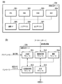
- FIG. 3A shows the hardware configuration of the image generation server 104
- FIG. 3B shows the software configuration of the image generation server 104.
- the hardware configuration will be described, and then the software configuration will be described.
- the image generation server 104 is configured of hardware included in a general information processing apparatus, that is, a CPU 301, a RAM 302, a ROM 303, a HDD 304, a communication I / F 305, an input device 306, and an output device 307.
- the CPU 301 is a processor that uses the RAM 302 as a work memory, executes various programs stored in the ROM 303, and integrally controls each unit of the image generation server 104.
- the functions of the processing modules shown in FIG. 3B are realized by the CPU 301 executing various programs.
- the RAM 302 temporarily stores the program read out from the ROM 303, the calculation result, and the like.
- the ROM 303 holds programs such as OS and data that do not need to be changed.
- the HDD 304 is a large-capacity storage device that stores a multi-viewpoint image read from the database server 103, a generated virtual viewpoint image, and the like, and may be an SSD or the like, for example.
- the communication I / F 305 is compatible with communication standards such as Ethernet and USB, and communicates with the database server 103, the client PC 105, and the controllers 106a to 106m.
- the input device 306 is a keyboard, a mouse or the like for the operator to perform various input operations.
- the output device 307 is a display device such as a monitor that displays information (UI screen or the like) necessary for the operator. When a touch panel display is adopted as the output device 117, it also serves as the input device 116 described above.
- the hardware configuration described above is also included in the client PC 105, for example.
- the image generation server 104 has five processing modules: a main control module 311, a drawing preprocessing module 312, a virtual viewpoint complementing module 313, a drawing module 314, and a distribution module 315.
- a virtual viewpoint image corresponding to one or more specified projection methods among the four types of predetermined projection methods such as the 2D method, 3D method, panoramic method, and 3D panoramic method described above. The description will be given assuming that it is generated. Note that the projection methods that can be specified are not limited to the above four types. As will be described later, the number of virtual viewpoints represented by the viewpoint information used to generate the virtual viewpoint image differs depending on the projection method.
- the main control module 311 is a module that plays a central role in generating a virtual viewpoint image according to the above-described instruction information, and issues various instructions to other processing modules. For example, when the 3D method is designated, the virtual viewpoint set by the controller 106 is not sufficient, and therefore the virtual viewpoint complementing module 313 is instructed to complement the missing virtual viewpoint. Then, the drawing module 314 is instructed to execute the drawing process using the two virtual viewpoints (the virtual viewpoint set by the user by the controller 106 and the virtual viewpoint obtained by the above complement). Then, the drawing processing result (two images corresponding to the two virtual viewpoints) received from the drawing module 314 is subjected to a combining process to generate one virtual viewpoint image by the 3D method.
- the main control module 311 can perform such a series of processes simultaneously in parallel according to the number of generations designated by the instruction information from the client PC 105, and generate and deliver a plurality of virtual viewpoint images.
- the drawing pre-processing module 312 acquires a multi-viewpoint image from the database server 103 by designating a time code at the time of image capturing.
- the multi-viewpoint images are captured by the cameras of the sensor systems 101a to 101n synchronously and stored in the database server 103 by the image recording device 102.
- the drawing preprocessing module 312 also performs processing of generating data (three-dimensional model) representing the three-dimensional shape of the foreground and background used in the drawing processing (rendering) in the drawing module 314 from the multi-viewpoint image.
- This three-dimensional model is generated using a shape estimation method (for example, Visual Hull), and is composed of, for example, a point cloud.
- the three-dimensional model is generated by another device such as the image recording device 102, and the drawing preprocessing module 312 acquires the three-dimensional model generated by another device together with the multi-viewpoint images. But it's okay.
- the virtual viewpoint complementing module 313 acquires viewpoint information (hereinafter, also referred to as “virtual camera parameter”) that specifies the positions and orientations (postures) of the virtual cameras 210a to 210m output by the controllers 106a to 106m, respectively.
- This viewpoint information may include not only the position and orientation of the virtual cameras 210a to 210m but also information such as magnification (zoom), for example.
- the number of virtual viewpoints required to generate one virtual viewpoint image differs depending on the projection method. For example, when the designated projection method is the 2D method, only one virtual viewpoint is sufficient. On the other hand, in the case of the 3D method, another virtual viewpoint having a binocular parallax relationship with the virtual viewpoint specified by the viewpoint information acquired from the controller 106 is required.
- the virtual viewpoint complementing module 313 complements the necessary number of virtual viewpoints according to the projection method specified by the instruction information, based on the virtual viewpoints related to the viewpoint information input from the controller 106. Thus, the insufficient amount of viewpoint information is generated.
- the complement of the virtual viewpoint will be described later.
- the rendering module 314 perspectively projects and renders a three-dimensional model of the foreground or background based on one or more virtual viewpoints specified by the viewpoint information received from the virtual viewpoint complementing module 313. Specifically, a multi-viewpoint image to be used for each point forming the three-dimensional model is selected, an appropriate pixel value in the selected multi-viewpoint image is acquired based on the virtual viewpoint, and color processing is performed. The drawing result is sent to the main control module 313.
- the distribution module 315 transmits the virtual viewpoint image generated as described above to the designated distribution destination.
- the delivery destinations of the plurality of virtual viewpoint images according to the plurality of projection methods may be different delivery destinations, or at least some delivery destinations may be the same. In the case of the present embodiment, it is possible to output one virtual viewpoint image to a plurality of distribution destinations, as described later.
- the virtual viewpoint image distributed by the image generation server 104 may be expressed as “stream”, and the number of distributions may be expressed as “stream number”.
- the image generation server 104 of the present embodiment applies various projection methods from a common multi-viewpoint image to generate one or more virtual viewpoint images, and sends them to one or more distribution destinations. It is characterized by transmitting (multi-stream output). According to such a method, it is possible to efficiently meet the requests of various users. For example, when a 3D system image and a panoramic system image are provided by using a conventional captured image that is not a virtual viewpoint image by the conventional method, the captured image that is required is different. In order to provide a 3D system image that is not a panoramic system, it is necessary to capture images for the right eye and the left eye, that is, two images in which the imaging positions are several cm apart and the imaging directions are almost the same.
- the image generation server 104 of the present embodiment acquires common multiple-viewpoint images that do not depend on the format of the image to be provided, and uses this to generate and provide images of various formats. You can Further, it is possible to provide images in various formats according to the virtual viewpoint arbitrarily designated by the user, which cannot be realized by a normal captured image.
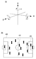
- FIG. 4A shows an orthogonal coordinate system in which the three-dimensional space used in this embodiment is represented by three axes of X axis, Y axis, and Z axis.
- This orthogonal coordinate system is set for each object shown in FIG. 4B, that is, the field 400, the ball 401 existing on the field 400, the player 402, and the like. Further, it may be set in equipment in the stadium such as audience seats and billboards. Specifically, first, the origin (0, 0, 0) is set at the center of the field 400. Then, the X axis is set in the long side direction of the field 400, the Y axis is set in the short side direction of the field 400, and the Z axis is set in the vertical direction with respect to the field 400. The direction of each axis is not limited to these. By using such a coordinate system, the position and orientation of the virtual camera 210 are designated.
- a vertex 501 represents the position of the virtual camera 210
- a vector 502 in the line-of-sight direction starting from the vertex 501 represents the posture of the virtual camera 210.
- the position of the virtual camera is represented by the component (x, y, z) of each axis
- the posture of the virtual camera 210 is represented by a unit vector having the component of each axis as a scalar.
- the vector 502 representing the posture of the virtual camera 210 passes through the center points of the front clip plane 503 and the rear clip plane 504.
- the view frustum of the virtual viewpoint which is the projection range (drawing range) of the three-dimensional model, is the space 505 sandwiched between the front clip plane 503 and the rear clip plane 504.
- FIG. 5B is a diagram for explaining the movement of the virtual viewpoint.
- a dashed arrow 511 represents movement of the virtual viewpoint
- a dashed arrow 512 represents rotation of the moved virtual viewpoint.
- the movement of the virtual viewpoint is represented by components (x, y, z) of each axis, and the rotation of the virtual viewpoint is yaw (Yaw) that is a rotation around the Z axis, pitch (Pitch) that is a rotation around the X axis, It is represented by a roll that is a rotation around the Y axis.
- Such movement and rotation of the virtual viewpoint is used not only in the operation of the virtual camera by the controllers 106a to 106m but also in complementing the virtual viewpoint described below.
- Complementing the virtual viewpoint is to generate an insufficient virtual viewpoint among two or more virtual viewpoints required when the projection method is the 3D method or the panoramic method, based on the virtual viewpoint set by the controller 106. Processing. Thereby, for example, in the case of the 3D method, two virtual viewpoints having a binocular parallax relationship are obtained.
- the virtual viewpoint obtained by this complement is a virtual viewpoint that is different from any of the plurality of virtual viewpoints set by the plurality of controllers 106a to 106m.
- FIG. 5C is a diagram for explaining the complementation of the virtual viewpoint when the 3D method is designated.
- the controller 106 inputs the virtual camera parameters in which the position of the virtual camera is the vertex 501 of the quadrangular pyramid 500 and the orientation thereof is the vector 502 to the virtual viewpoint complementing module 313.
- the above-described movement and rotation are performed on the virtual viewpoint specified by the input virtual camera parameter so that a relationship between the virtual viewpoint and the binocular parallax is obtained.
- a virtual viewpoint is newly generated in which the position of the virtual camera 210 is the vertex 501 'of the quadrangular pyramid 500' and the posture thereof is the vector 502 '.
- the user may specify an appropriate value for realizing the binocular parallax via a UI screen (not shown), or a predetermined value prepared in advance may be applied.
- an appropriate amount of movement and amount of rotation that realizes binocular parallax at a plurality of positions in the target three-dimensional space (for example, positions shifted at predetermined intervals in each of the X, Y, and Z axes) are obtained in advance,
- An LUT is prepared in which the plurality of positions are associated with the obtained movement amount and rotation amount. Then, the movement amount and the rotation amount corresponding to the position of the virtual viewpoint set by the controller 106 may be determined by the interpolation process with reference to the LUT.
- the drawing processing is performed with the virtual viewpoint represented by the quadrangular pyramid 500 for the left eye and the virtual viewpoint represented by the quadrangular pyramid 500 ′ for the right eye, and the images of the respective rendering results are, for example, left and right.
- the images of the respective rendering results are, for example, left and right.
- the virtual viewpoint complementing module 313 complements the necessary number of virtual viewpoints in the specified projection method from the virtual viewpoints set by the arbitrary controller 106.
- the method of complementing the virtual viewpoint differs depending on the projection method.
- the complementing method in the case of the 3D method is as described above, but in the case of the panoramic method, the number of virtual viewpoints necessary to cover the range of up to 360 degrees based on the virtual viewpoint set by the controller 106 is set. It will be complemented. For example, when the number of virtual viewpoints required to cover the entire 360-degree circumference is six, the controller 106 sets the remaining five virtual viewpoints so that the drawing ranges of the respective virtual viewpoints are adjacent. The set reference virtual viewpoint is moved and rotated to be complemented.
- the user may specify an appropriate value via a UI screen (not shown) as in the case of the 3D method, or a predetermined value prepared in advance may be applied. Further, the appropriate movement amount and rotation amount may be obtained using a LUT prepared in advance. Further, another virtual viewpoint may be generated by changing only the direction without changing the position of the reference virtual viewpoint. A panoramic virtual viewpoint image is obtained by synthesizing the images thus generated corresponding to the respective six virtual viewpoints. Further, the 3D panoramic method is a combination of the 3D method and the panoramic method.
- two panoramic images are generated so as to have the binocular parallax.
- 5 out of 11 are obtained by the panoramic method so that the drawing ranges of the respective virtual viewpoints are adjacent to each other, and the remaining 6 are obtained by the 3D method to obtain an appropriate movement amount and rotation amount for the binocular parallax. It can be obtained from the above six items by using.
- a 3D panoramic virtual viewpoint image is obtained.
- the insufficient virtual viewpoints can be obtained by moving and / or rotating the reference virtual viewpoints. Therefore, for example, even when a panoramic virtual viewpoint image is generated, the same number of virtual viewpoints is required. It is not necessary to prepare the number of controllers 106.
- the virtual viewpoints used for generating the respective virtual viewpoint images may be partially common or different.
- the virtual viewpoint image of the 3D method may be generated based on the virtual viewpoint corresponding to the virtual viewpoint image of the 2D method, or the virtual viewpoint corresponding to the virtual viewpoint image of the 2D method and the reference of the virtual viewpoint image of the 3D method. May be different from the virtual viewpoint.
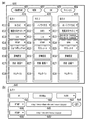
- FIGS. 6A and 6B are diagrams showing an example of a UI screen displayed on a monitor or the like of the client PC 105 for the user to specify the projection method and the delivery destination to create instruction information.
- FIG. 6A shows a main screen 600
- FIG. 6B shows a sub screen for detailed setting. First, the main screen 600 will be described.
- the operator who creates the instruction information first presses the new creation button 601 on the main screen 600.
- the setting list 610 for inputting the information necessary for generating and delivering one virtual viewpoint image is displayed on the main screen 600.
- three setting lists 610, 620 and 630 are displayed, which means that the new creation button 601 has been pressed three times.
- the delete button 602 is used to delete an arbitrary setting list
- the OK button 603 is used when the setting list has been created
- the cancel button 604 is used to stop the setting input operation.
- three virtual viewpoint images are generated by different projection methods and output to four different distribution destinations will be described as an example.
- Each setting list may be displayed as a sub screen different from the main screen 600.
- the OK button 603 may be provided in each of the plurality of setting lists. In this case, it is possible to issue a virtual viewpoint image generation / distribution instruction in units of setting lists.
- Each setting list 610 to 630 includes setting items 611 to 615 for specifying main parameters required to generate each virtual viewpoint image, a detailed setting button 616, a status display column 617, and a thumbnail display column 618, respectively. Exists.
- each element that constitutes the setting list will be described in order.
- the projection method is designated.
- four types of projection methods 2D method, 3D method, panoramic method, and 3D panoramic method, are displayed in a pull-down display, and the operator selects one from them.
- 3D method is specified in the setting item 611 of the setting list 610
- Panorama method is specified in the setting item 611 of the setting list 620
- 3D panorama method is specified in the setting item 611 of the setting list 630. ing.
- the delivery destination is specified.
- the distribution destinations include a video sharing site, an SNS, a broadcasting center of TV stations, and public viewing.
- the content of the delivery destination candidate created in advance may be displayed in a pull-down manner, and the operator may select one from the pull-down display, or the delivery destination address such as a URL may be directly input by the operator.
- the moving picture sharing site is not limited to a specific one, and a plurality of different moving picture sharing sites can be designated. Further, it is possible to specify different URLs or the like even for the same video sharing site.
- the names are displayed so that they can be identified. Here, for the sake of convenience, they can be identified as "video sharing site 1" and "video sharing site 2".
- video sharing site 1 is specified in the setting item 612 of the setting list 610
- SNS1 is specified in the setting item 612 of the setting list 620
- video sharing site 2 is specified in the setting item 612 of the setting list 630. It is specified.
- the delivery format and time code are specified.
- the multi-viewpoint images stored in the database server 103 are attached with the time code, which is time information at the time of image capturing.
- the time code is time information at the time of image capturing.
- the target data can be uniquely identified and acquired.
- on-demand distribution and live distribution are displayed in a pull-down display as the distribution format options, and the operator selects one of them.
- a start time code and an end time code are further designated. Based on such a user instruction, a virtual viewpoint image for on-demand distribution is generated using the multiple viewpoint images identified by the start time code and the end time code.
- the time code at this time is specified in the format such as "2018/08/30 15: 00: 00: 00-2018 / 08/30 15: 30: 00: 20", and the date, time, frame number, etc. Composed of.
- the virtual viewpoint image generated according to the time code and delivered on-demand is used for, for example, replay reproduction of a highlight scene.
- live distribution the processes from the imaging by each camera to the generation and distribution of the virtual viewpoint image are processed in real time. Therefore, it is not practical for the operator to manually specify the time code.
- the designation is ended by selecting the letter notation such as “Live” indicating that the live distribution is performed, and it is not necessary to designate the start and end time codes.
- the image generation server 104 automatically designates the latest time code immediately after recording and sequentially acquires the multi-viewpoint images from the database server 103.
- a plurality of viewpoint images captured by each camera are sequentially acquired, a virtual viewpoint image is generated in real time, and sequentially output to a designated distribution destination. It is also possible to add on-demand distribution as another stream from the middle of live distribution.
- the data format of the stream output from the image generation server 104 is designated.
- This setting item 614 is preferably linked to the setting item 613 described above. That is, when live distribution is designated in the setting item 613 of each setting list, a streaming protocol such as RTMP (Real Time Message Protocol) or HLS (HTTP Live Streaming) is displayed as an option, and Let the operator choose from.
- a video file format such as MP4, AVI, MOV is displayed as an option, and the operator is allowed to select from the options.
- “RTMP” is specified in the setting lists 610 and 620 in which live distribution is specified
- MP4 is specified in the setting list 630 in which on-demand distribution is specified.
- controller identification information for designating which controller 106 is used to generate a virtual viewpoint image.
- the operator selects one from input devices such as a joystick and a tablet displayed as options.
- An identifier is assigned to each of the controllers 106a to 106m, and here, by designating the identifier, which controller is used to generate a virtual viewpoint image is designated.
- an alphabet is added to the type name of the controller such as “joystick A” or “tablet A” to enable identification. Note that the same identifier can be designated for generation of a plurality of virtual viewpoint images.
- tablette A is designated in the setting list 620 and “tablet B” is designated in the setting list 630, but both can be set to “tablet A”, for example.
- two virtual viewpoint images by different projection methods are generated using the virtual viewpoint set on the "tablet A”.
- the type of controller is not limited by the projection method designated by the setting item 611, and different devices of the same model can be designated.
- the detailed setting button 616 is a button for displaying the sub screen for detailed setting shown in FIG. 6B.
- the sub screen for detailed setting will be described later.
- a character string indicating the processing status of the generation and distribution of the virtual viewpoint image (for example, “during distribution”, “completed”, “error”, etc.) is displayed.
- “during distribution” indicates that the virtual viewpoint image is being output to the specified distribution destination
- “completion” indicates that the generation and distribution processing has been completed
- “error” indicates that the virtual viewpoint image has been generated and distributed. Indicates that an error has occurred.
- the contents of the status display are not limited to the above three.
- a thumbnail image of the virtual viewpoint image being processed is displayed in the thumbnail display field 618.
- the operator can intuitively understand whether or not the contents specified by each setting item are as intended, and whether or not they are normally processed.
- a message or the like indicating that the error is occurring is displayed.
- the UI screen shown in FIG. 6A is merely an example, and any UI screen can be used as long as the desired projection method can be specified and one or more virtual viewpoint images can be generated and their distribution destinations can be specified. Such a UI screen may be used.
- an operator may directly input an arbitrary character string, numerical value, or the like, instead of selecting from preset options.
- the resolution of the virtual viewpoint image to be generated is specified.
- FHD Full HD
- 4K 4K
- 8K etc.
- the frame rate of the virtual viewpoint image to be generated is designated.
- 29.97, 30 fps, 59.94 fps, 60 fps, etc. can be designated, and the operator selects one from these displayed as options.
- the encoding method for the virtual viewpoint image to be output is designated.
- H.264. H.264, H.264. 265, HEVC, etc. can be designated, and the operator selects one from these displayed as options.
- an operator may directly input an arbitrary numerical value instead of specifying from the options.
- the setting field 644 the content specified by the setting item 614 (output data format) on the main screen 600 described above is set. For example, when “RTMP” is specified in the setting item 614, the setting field 644 also becomes “RTMP”. Then, in the adjacent input field 645, the URL of the RTMP server which is the output destination is input. If “MP4” is specified in the setting item 614 on the main screen, the setting field 644 also becomes “MP4”. Then, in the adjacent input field 645, the path and API of the file server that is the output destination is input. Further, by pressing the add button 646 next to it, the delivery destination can be added. As a result, one virtual viewpoint image generated according to the setting list can be output to a plurality of different distribution destinations.
- the add button 646 is pressed once, "RTMP" is entered in the setting field 644 'relating to the other delivery destination, and its URL is entered in its input field 645'.
- the setting field 644 of the sub screen 640 and the setting item 614 of the main screen 600 are linked, and when the content of the setting field 644 is changed, the content of the setting item 614 is also changed.
- the output data formats of the delivery destinations to be added do not have to be the same, and it is possible to specify “HLS” instead of “RTMP”, for example.
- the detailed setting items are not limited to the above as long as they are parameters for generating the virtual viewpoint image.
- the operator designates various items relating to the generation and distribution of the virtual viewpoint image, creates the above-mentioned instruction information, and sends it to the image generation server 104.
- a total of three virtual viewpoint images are generated by different projection methods based on virtual viewpoints from different controllers 106 and output to different distribution destinations.
- a common projection method may be designated in the setting item 611 of each setting list, and an identifier of a different controller 106 may be designated in the setting item 615.
- the live distribution and the on-demand distribution are combined, but it is also possible to distribute all the streams live. It is also possible to archive virtual viewpoint images generated with the same settings during live distribution, and to output them as on-demand distribution during live distribution or after completion.
- FIG. 7A is a flowchart showing a rough flow of virtual viewpoint image generation / distribution processing. This series of processing is realized by the CPU 301 executing a predetermined program and operating each processing module shown in FIG.
- step S ⁇ b> 701 the main control module 311 receives the instruction information created for each setting list unit from the client PC 105.
- the drawing preprocessing module 312 is instructed to acquire a multi-viewpoint image.
- the acquisition of the multi-viewpoint images corresponding to the time code specified in each setting list is instructed.
- the drawing preprocessing module 312 that has received the instruction specifies a time code based on the content of the setting item 613 in the setting list, and acquires a multi-viewpoint image from the database server 103.
- each processing module operates under the control of the main control module 311 to generate a designated number of virtual viewpoint images according to the instruction information, and output the virtual viewpoint images to the designated distribution destination.
- a plurality of virtual viewpoint images corresponding to a common time code can be generated as a plurality of virtual viewpoint images of different projection methods.
- the instruction information is composed of a plurality of setting lists
- a series of processes based on each setting list may be executed in parallel or sequentially. Details of the generation and distribution of the virtual viewpoint image in this step will be described with reference to another flow shown in FIG. Since the present embodiment is premised on moving images, the flow shown in FIG. 7B is executed in frame units.
- the main control module 311 identifies the projection method specified in the processing target setting list, and determines the next step. Specifically, if the 2D method has been specified, to S712; if the 3D method has been specified, to S714; if the panoramic method has been specified, to S716, if the 3D panoramic method has been specified Advances to S718, respectively.
- a process of generating a 2D virtual viewpoint image is executed.
- the generated virtual viewpoint image of the 2D method is output to the distribution destination specified in the setting list.
- a process of generating a 3D virtual viewpoint image is executed, and in S715, the 3D virtual viewpoint image is output to the delivery destination specified in the setting list.
- a process of generating a panoramic virtual viewpoint image is executed, and in step S717, the panoramic virtual viewpoint image is output to the distribution destination specified in the setting list.
- FIG. 8A is a flowchart showing details of virtual viewpoint image generation by the 2D method.
- step S801 the virtual viewpoint complementing module 313 acquires virtual camera parameters from the controller 106 corresponding to the identifier specified in the setting list.
- This virtual camera parameter includes at least information that specifies the position and orientation of the virtual camera.
- FIG. 9A shows an example of a virtual viewpoint set for a shoot scene. It is assumed that the virtual camera 210 is set at a position facing the direction of the ball 401 from outside the penalty area, as indicated by a mark 901 in the diagram shown in FIG. 4B, and corresponds to the mark 901. It is assumed that the virtual camera parameters to be acquired have been acquired. It is assumed that the Z-axis of the virtual viewpoint set in the diagram shown in FIG. 9A is fixed at a height that is the line of sight of the player.
- step S ⁇ b> 802 the drawing module 314 uses the three-dimensional model of the foreground or background provided from the drawing preprocessing module 312 to perform drawing processing by perspective projection from the virtual viewpoint represented by the virtual camera parameter acquired in step S ⁇ b> 801.
- the drawing result does not need to be combined and converted, so that the drawing result is output as it is as a virtual viewpoint image for distribution.
- FIG. 9B shows a 2D virtual viewpoint image corresponding to the virtual viewpoint of the mark 901 described above. In this case, a virtual viewpoint image from the player's eyes outside the penalty area can be obtained.
- FIG. 8B is a flowchart showing details of virtual viewpoint image generation by the 3D method.
- the 3D method two virtual viewpoints are used to generate two images having a binocular parallax relationship.
- the virtual viewpoint complementing module 313 acquires the virtual camera parameter from the controller 106 corresponding to the identifier specified in the setting list.
- the virtual camera 210 facing the direction of the ball 401 from the position of the goalkeeper is set as shown by a mark 902, and the virtual camera parameter corresponding to the mark 902 is set. It is assumed to have been acquired.
- the virtual viewpoint complementing module 313 complements another virtual viewpoint for realizing the binocular parallax based on the virtual camera parameter acquired in S811.
- the complementing method at this time is as described above.
- step S813 the drawing module 314 uses the foreground and background three-dimensional models provided from the drawing preprocessing module 312 to perform drawing processing by perspective projection for each of the virtual viewpoint acquired in step S811 and the virtual viewpoint complemented in step S812. To do.
- the main control module 311 arranges the rendering results (two images corresponding to two virtual viewpoints with parallax) in S813 side by side to perform a combining process to generate one 3D virtual viewpoint image. ..
- the format in which two images with binocular parallax are arranged side by side is called the Side by Side format.
- the 3D virtual viewpoint image thus obtained is distributed.
- FIG. 9C shows a 3D virtual viewpoint image corresponding to the virtual viewpoint of the mark 902 described above. In this case, the virtual viewpoint image is the same as that of the goalkeeper. If a headset using a smartphone compatible with 3D display or a head mounted display is attached, the user can stereoscopically view the virtual viewpoint image. In the example of FIG. 9C, the user can experience a powerful scene in which the shot ball is in front of the user, as if he / she became a goalkeeper.
- FIG. 8C is a flowchart showing details of virtual viewpoint image generation by the panoramic method.
- the panoramic method uses more virtual viewpoints than the 3D method in order to cover the entire 360 degrees at the maximum.
- the virtual viewpoint complementing module 313 acquires the virtual camera parameter from the controller 106 corresponding to the identifier specified in the setting list. 9A, it is assumed that the virtual camera 210 is set at a position facing the ball 401 in the penalty area as indicated by a mark 903, and the virtual camera parameter corresponding to the mark 903 is set. Is acquired.
- the virtual viewpoint complementing module 313 complements the number of virtual viewpoints necessary to generate the panoramic image in the panoramic method based on the virtual camera parameters acquired in S821.
- the complementing method at this time is as described above. It should be noted that if the number of virtual viewpoints to be complemented is small, a panoramic image in a range narrower than the entire circumference will be produced accordingly.
- step S823 the drawing module 314 uses the three-dimensional model of the foreground or background provided from the drawing preprocessing module 312 to perform perspective projection for each of the virtual viewpoint acquired in step S821 and the one or more virtual viewpoints complemented in step S822. The drawing process is performed.
- the main control module 311 converts the drawing result in S823 (a plurality of images corresponding to a plurality of virtual viewpoints) into an equirectangular projection, and generates one virtual viewpoint image of the panoramic method.
- the panoramic virtual viewpoint image thus obtained is distributed.
- FIG. 9D shows a panoramic virtual viewpoint image corresponding to the virtual camera 210 of the mark 903 described above.
- the virtual viewpoint image is 360 degrees around the position 903 in the penalty area.
- FIG. 8D is a flowchart showing details of virtual viewpoint image generation by the 3D panoramic method.
- the 3D panoramic method in order to cover the entire circumference of 360 degrees and to realize binocular parallax, twice the number of virtual viewpoints as in the panoramic method is used.
- the virtual viewpoint complementing module 313 acquires the virtual camera parameter from the controller 106 corresponding to the identifier designated in the setting list. Now, as in the case of the panorama method described above, it is assumed that the virtual camera 210 is set at the position indicated by the mark 903 (see FIG. 9A), and the virtual camera parameter corresponding to the mark 903 is acquired. And
- the virtual viewpoint complementing module 313 covers the entire circumference by the 3D panoramic method based on the virtual camera parameters acquired in S831, and complements the number of virtual viewpoints necessary for generating a binocular parallax image.
- the complementing method at this time is as described above.
- step S833 the drawing module 314 draws by perspective projection the virtual viewpoint acquired in step S831 and the plurality of virtual viewpoints complemented in step S832 by using the foreground and background three-dimensional models provided from the drawing preprocessing module 312. Perform processing.
- the main control module 311 divides the drawing result (a plurality of images corresponding to a plurality of virtual viewpoints) in S833 into one for the left eye and one for the right eye, and converts each image group into an equirectangular projection. As a result, one panoramic image is obtained for the left eye and one image for the right eye.
- the main control module 311 arranges the rendering results (two panoramic images with parallax) in S834 one above the other to perform a synthesis process to generate one 3D panoramic virtual viewpoint image.
- the format in which two images with binocular parallax are arranged vertically is called Top and Bottom format.
- the 3D panoramic virtual viewpoint image thus obtained will be distributed.
- FIG. 9E shows a 3D panoramic virtual viewpoint image corresponding to the virtual camera 210 of the mark 903 described above. In this case as well, as in the case of FIG. 9D described above, the image is a 360-degree omnidirectional image around the position 903 in the penalty area, and a virtual viewpoint image with binocular parallax.
- the user can wear the above-described headset or the like to stereoscopically view the virtual viewpoint image including the entire circumference of 360 degrees.
- the user can follow the shooting scene by simply turning the user's head in the desired direction with a sense of realism as if the user were standing in the penalty area.
- the above is the virtual viewpoint image generation processing by each projection method.
- the virtual viewpoint image generation process by each of the above-described projection methods is an example, and the present invention is not limited to the above contents. It suffices that the virtual viewpoint image corresponding to each projection method can be generated, and the processing order, the image format, and the like can be appropriately changed.
- the process of generating and distributing the virtual viewpoint image according to the above-described embodiment may be overloaded depending on the number of generated virtual viewpoint images and the capacity of the multiple viewpoint images.
- a high-resolution multi-viewpoint image such as 4K or 8K
- the capacity of the multi-viewpoint image becomes large, and depending on the number of virtual viewpoint images to be generated, it is difficult for one image generation server 104 to generate them without delay. Can be. In that case, it becomes impossible to fully function as a system, such as simultaneous real-time output in response to a plurality of live distribution requests.
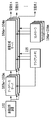
- a distributed configuration as shown in FIG. 10 may be adopted.
- a plurality of image generation servers 104a to 104m and a plurality of database servers 103a to 103m are prepared in advance, and among them, the database server required to correspond to the number of generations designated by the instruction information. And image generation server.
- the image generation servers 104a to 104m are connected to the database servers 103a to 103m on a one-to-one basis. Then, the same multi-viewpoint image is stored in the database servers 103a to 103m by the image recording apparatus 102, and the image generation servers 104a to 104m respectively acquire the multi-viewpoint image. Then, each of the image generation servers 104a to 104m generates one virtual viewpoint image according to the instruction information received from the client PC 105, and outputs it to the designated distribution destination. Since the database servers 103a to 103m all store the same multi-viewpoint image, they may be configured as cache servers. Note that, also in the example of FIG. 10, the single client PC 105 is used to create the instruction information for each of the image generation servers 104a to 104m, but a plurality of units may be used.
- a dedicated management device for controlling the image generation servers 104a to 104m and the database servers 103a to 103m is provided, and the process of allocating to each image generation server 104 is executed instead of the determination process of S711 in the flow of FIG. 7B. It may be configured to.
- the function of the management device may be provided in the tablets as the controllers 106a to 106m. Distribution of the generated virtual viewpoint image may be performed by each of the image generation servers 104a to 104m, or may be configured such that the management device performs the distribution process instead.
- some of the plurality of image generation servers 104a to 104m may generate / deliver a plurality of virtual viewpoint images.
- the management device determines the number of image generation servers to be used based on the format (projection method) of virtual viewpoint images to be generated and distributed or the number of virtual viewpoint images. Then, the management device controls the duplication and output of the multi-viewpoint image by the image recording device 102 so that the same multi-viewpoint image is stored in the same number of database servers as the number of image generation servers used.
- the plurality of virtual viewpoint images generated by the plurality of image generation servers may be output to different distribution destinations.
- the number of database servers and the number of image generation servers to be used can be flexibly set according to the number of generated virtual viewpoint images even when the multi-viewpoint images have a high resolution and a large capacity. it can. By adopting such a distributed configuration, it is possible to cope with a case where a high-quality virtual viewpoint image is live-distributed to many distribution destinations.
- the projection method can be freely selected.
- the virtual viewpoints corresponding to the respective virtual viewpoint images can be set independently. This makes it possible to generate and deliver various types of virtual viewpoint images viewed from various viewpoints in a three-dimensional space of an imaged scene. For example, for a soccer match at a stadium, a 2D image of a virtual viewpoint that follows the ball is delivered to a broadcasting center of a TV station while a 3D image of a virtual viewpoint from the viewpoint of a player such as a goalkeeper is delivered to a movie theater. Etc. can be simultaneously distributed to public viewing such as.
- a panorama format or 3D panorama format image in which a high-line scene such as a shot scene can be viewed 360 degrees freely within the penalty area to a video distribution site or SNS.
- the application target of the present embodiment is not limited to sports scenes, but can be widely applied to, for example, concerts of famous artists, and it is possible to provide users with various new viewing experiences using virtual viewpoint images. ..
- the present invention supplies a program that implements one or more functions of the above-described embodiments to a system or apparatus via a network or a storage medium, and one or more processors in a computer of the system or apparatus read and execute the program. It can also be realized by the processing. It can also be realized by a circuit (for example, ASIC) that realizes one or more functions.
- a circuit for example, ASIC
Landscapes
- Engineering & Computer Science (AREA)
- Theoretical Computer Science (AREA)
- Physics & Mathematics (AREA)
- Multimedia (AREA)
- Signal Processing (AREA)
- General Physics & Mathematics (AREA)
- General Engineering & Computer Science (AREA)
- Human Computer Interaction (AREA)
- Computer Graphics (AREA)
- Computing Systems (AREA)
- Geometry (AREA)
- Computer Hardware Design (AREA)
- Software Systems (AREA)
- Processing Or Creating Images (AREA)
- Image Generation (AREA)
- Testing, Inspecting, Measuring Of Stereoscopic Televisions And Televisions (AREA)
- User Interface Of Digital Computer (AREA)
Priority Applications (5)
| Application Number | Priority Date | Filing Date | Title |
|---|---|---|---|
| KR1020217014249A KR102551691B1 (ko) | 2018-11-14 | 2019-11-08 | 정보 처리 시스템, 정보 처리 방법, 및 저장 매체 |
| EP19884420.1A EP3882866B1 (en) | 2018-11-14 | 2019-11-08 | Information processing system, information processing method, and program |
| CN201980075013.6A CN113016010B (zh) | 2018-11-14 | 2019-11-08 | 信息处理系统、信息处理方法和存储介质 |
| US17/315,646 US20210266511A1 (en) | 2018-11-14 | 2021-05-10 | Information processing system, information processing method, and storage medium |
| US17/848,426 US11956408B2 (en) | 2018-11-14 | 2022-06-24 | Information processing system, information processing method, and storage medium |
Applications Claiming Priority (2)
| Application Number | Priority Date | Filing Date | Title |
|---|---|---|---|
| JP2018-213769 | 2018-11-14 | ||
| JP2018213769A JP7237538B2 (ja) | 2018-11-14 | 2018-11-14 | 情報処理装置、それを含むシステム、情報処理方法、およびプログラム |
Related Child Applications (1)
| Application Number | Title | Priority Date | Filing Date |
|---|---|---|---|
| US17/315,646 Continuation US20210266511A1 (en) | 2018-11-14 | 2021-05-10 | Information processing system, information processing method, and storage medium |
Publications (1)
| Publication Number | Publication Date |
|---|---|
| WO2020100770A1 true WO2020100770A1 (ja) | 2020-05-22 |
Family
ID=70730893
Family Applications (1)
| Application Number | Title | Priority Date | Filing Date |
|---|---|---|---|
| PCT/JP2019/043996 Ceased WO2020100770A1 (ja) | 2018-11-14 | 2019-11-08 | 情報処理システム、情報処理方法、およびプログラム |
Country Status (6)
| Country | Link |
|---|---|
| US (2) | US20210266511A1 (enExample) |
| EP (1) | EP3882866B1 (enExample) |
| JP (1) | JP7237538B2 (enExample) |
| KR (1) | KR102551691B1 (enExample) |
| CN (1) | CN113016010B (enExample) |
| WO (1) | WO2020100770A1 (enExample) |
Families Citing this family (7)
| Publication number | Priority date | Publication date | Assignee | Title |
|---|---|---|---|---|
| JP7574565B2 (ja) * | 2020-07-31 | 2024-10-29 | 株式会社リコー | 通信端末、通信システム、通信方法、及びプログラム |
| WO2022107669A1 (ja) * | 2020-11-20 | 2022-05-27 | ソニーグループ株式会社 | 情報処理装置、情報処理方法、情報処理システム |
| JP7672842B2 (ja) | 2021-02-26 | 2025-05-08 | キヤノン株式会社 | 情報処理装置、情報処理方法、およびプログラム |
| JP7690301B2 (ja) | 2021-02-26 | 2025-06-10 | キヤノン株式会社 | 情報処理装置、それを含むシステム、情報処理方法およびプログラム |
| US12206838B2 (en) * | 2021-09-24 | 2025-01-21 | Sony Group Corporation | View-independent multi-camera volumetric capture system |
| JP7746197B2 (ja) * | 2022-03-10 | 2025-09-30 | キヤノン株式会社 | 画像処理システム、画像処理方法及びコンピュータプログラム |
| EP4443273A1 (en) * | 2023-03-31 | 2024-10-09 | Canon Kabushiki Kaisha | Display control apparatus, display control method, and program |
Citations (3)
| Publication number | Priority date | Publication date | Assignee | Title |
|---|---|---|---|---|
| JP2006352539A (ja) * | 2005-06-16 | 2006-12-28 | Sharp Corp | 広視野映像システム |
| JP2014215828A (ja) | 2013-04-25 | 2014-11-17 | シャープ株式会社 | 画像データ再生装置、および視点情報生成装置 |
| JP2017069787A (ja) * | 2015-09-30 | 2017-04-06 | 徹平 江里口 | 動画像処理装置、動画像処理方法、動画像処理プログラム及び動画像処理表示システム。 |
Family Cites Families (25)
| Publication number | Priority date | Publication date | Assignee | Title |
|---|---|---|---|---|
| US5850352A (en) * | 1995-03-31 | 1998-12-15 | The Regents Of The University Of California | Immersive video, including video hypermosaicing to generate from multiple video views of a scene a three-dimensional video mosaic from which diverse virtual video scene images are synthesized, including panoramic, scene interactive and stereoscopic images |
| US5729471A (en) * | 1995-03-31 | 1998-03-17 | The Regents Of The University Of California | Machine dynamic selection of one video camera/image of a scene from multiple video cameras/images of the scene in accordance with a particular perspective on the scene, an object in the scene, or an event in the scene |
| US7614954B2 (en) * | 2002-11-20 | 2009-11-10 | Sega Corporation | Game image display control program, game device, and recoding medium |
| US20070216782A1 (en) * | 2006-03-20 | 2007-09-20 | Donald Lee Chernoff | Method of processing and storing files in a digital camera |
| CN102598652B (zh) * | 2009-10-30 | 2015-08-12 | 佳能株式会社 | 信息处理设备和方法 |
| US20110126160A1 (en) | 2009-11-23 | 2011-05-26 | Samsung Electronics Co., Ltd. | Method of providing 3d image and 3d display apparatus using the same |
| JP2011248723A (ja) | 2010-05-28 | 2011-12-08 | Sony Corp | 画像処理装置および方法、並びにプログラム |
| US9485497B2 (en) * | 2010-09-10 | 2016-11-01 | Reald Inc. | Systems and methods for converting two-dimensional images into three-dimensional images |
| KR20120078649A (ko) | 2010-12-31 | 2012-07-10 | 한국전자통신연구원 | 카메라를 구비한 휴대용 영상 통화 장치 및 그 방법 |
| KR101752691B1 (ko) * | 2011-12-14 | 2017-07-03 | 한국전자통신연구원 | 시점 선택이 가능한 3차원 가상 콘텐츠 동영상을 제공하는 장치 및 그 방법 |
| US9009092B2 (en) * | 2012-07-19 | 2015-04-14 | Microsoft Technology Licensing, Llc | Creating variations when transforming data into consumable content |
| KR101415147B1 (ko) * | 2012-08-10 | 2014-07-08 | 광운대학교 산학협력단 | 가상시점 영상 생성을 위한 경계 잡음 제거 및 홀 채움 방법 |
| KR102089976B1 (ko) | 2012-12-28 | 2020-03-18 | 삼성전자주식회사 | 엑스선 영상 장치, 엑스선 영상 생성 방법 및 3차원 영상 장치 |
| JP6443654B2 (ja) * | 2013-09-26 | 2018-12-26 | Tianma Japan株式会社 | 立体画像表示装置、端末装置、立体画像表示方法、及びそのプログラム |
| KR101678861B1 (ko) | 2015-07-28 | 2016-11-23 | 엘지전자 주식회사 | 이동단말기 및 그 제어방법 |
| EP3151554A1 (en) * | 2015-09-30 | 2017-04-05 | Calay Venture S.a.r.l. | Presence camera |
| US10694081B2 (en) * | 2016-03-10 | 2020-06-23 | Sony Corporation | Information processing apparatus and information processing method |
| CN109565605B (zh) | 2016-08-10 | 2021-06-29 | 松下电器(美国)知识产权公司 | 拍摄技术生成方法以及影像处理装置 |
| JP6539253B2 (ja) * | 2016-12-06 | 2019-07-03 | キヤノン株式会社 | 情報処理装置、その制御方法、およびプログラム |
| JP6482580B2 (ja) * | 2017-02-10 | 2019-03-13 | キヤノン株式会社 | 情報処理装置、情報処理方法、およびプログラム |
| JP7086522B2 (ja) * | 2017-02-28 | 2022-06-20 | キヤノン株式会社 | 画像処理装置、情報処理方法及びプログラム |
| US11218683B2 (en) | 2017-03-22 | 2022-01-04 | Nokia Technologies Oy | Method and an apparatus and a computer program product for adaptive streaming |
| JP6648061B2 (ja) | 2017-03-28 | 2020-02-14 | Kddi株式会社 | クライアント状態に応じた映像を配信する映像配信装置、システム、プログラム及び方法 |
| JP7249755B2 (ja) | 2018-10-26 | 2023-03-31 | キヤノン株式会社 | 画像処理システムおよびその制御方法、プログラム |
| JP7378243B2 (ja) | 2019-08-23 | 2023-11-13 | キヤノン株式会社 | 画像生成装置、画像表示装置および画像処理方法 |
-
2018
- 2018-11-14 JP JP2018213769A patent/JP7237538B2/ja active Active
-
2019
- 2019-11-08 CN CN201980075013.6A patent/CN113016010B/zh active Active
- 2019-11-08 EP EP19884420.1A patent/EP3882866B1/en active Active
- 2019-11-08 KR KR1020217014249A patent/KR102551691B1/ko active Active
- 2019-11-08 WO PCT/JP2019/043996 patent/WO2020100770A1/ja not_active Ceased
-
2021
- 2021-05-10 US US17/315,646 patent/US20210266511A1/en not_active Abandoned
-
2022
- 2022-06-24 US US17/848,426 patent/US11956408B2/en active Active
Patent Citations (3)
| Publication number | Priority date | Publication date | Assignee | Title |
|---|---|---|---|---|
| JP2006352539A (ja) * | 2005-06-16 | 2006-12-28 | Sharp Corp | 広視野映像システム |
| JP2014215828A (ja) | 2013-04-25 | 2014-11-17 | シャープ株式会社 | 画像データ再生装置、および視点情報生成装置 |
| JP2017069787A (ja) * | 2015-09-30 | 2017-04-06 | 徹平 江里口 | 動画像処理装置、動画像処理方法、動画像処理プログラム及び動画像処理表示システム。 |
Non-Patent Citations (1)
| Title |
|---|
| See also references of EP3882866A4 |
Also Published As
| Publication number | Publication date |
|---|---|
| CN113016010A (zh) | 2021-06-22 |
| KR102551691B1 (ko) | 2023-07-06 |
| US20220321856A1 (en) | 2022-10-06 |
| JP7237538B2 (ja) | 2023-03-13 |
| EP3882866B1 (en) | 2024-05-15 |
| CN113016010B (zh) | 2024-07-16 |
| KR20210072086A (ko) | 2021-06-16 |
| JP2020080101A (ja) | 2020-05-28 |
| US20210266511A1 (en) | 2021-08-26 |
| EP3882866A4 (en) | 2022-08-10 |
| US11956408B2 (en) | 2024-04-09 |
| EP3882866A1 (en) | 2021-09-22 |
Similar Documents
| Publication | Publication Date | Title |
|---|---|---|
| JP7237538B2 (ja) | 情報処理装置、それを含むシステム、情報処理方法、およびプログラム | |
| US11627251B2 (en) | Image processing apparatus and control method thereof, computer-readable storage medium | |
| KR102407283B1 (ko) | 콘텐트를 전달 및/또는 콘텐트를 재생하기 위한 방법들 및 장치 | |
| CN107615338B (zh) | 用于生成和使用降低分辨率图像并且/或者将这样的图像传送到重放或内容分发设备的方法和装置 | |
| EP2490179B1 (en) | Method and apparatus for transmitting and receiving a panoramic video stream | |
| JP6849430B2 (ja) | 画像処理装置、画像処理方法、及びプログラム | |
| US10681276B2 (en) | Virtual reality video processing to compensate for movement of a camera during capture | |
| JP7672842B2 (ja) | 情報処理装置、情報処理方法、およびプログラム | |
| JP2018507650A (ja) | コンテンツの生成、送信、および/または、再生をサポートするための方法および装置 | |
| JP7378243B2 (ja) | 画像生成装置、画像表示装置および画像処理方法 | |
| JP2010154052A (ja) | 複数カメラ制御システム | |
| WO2020036644A2 (en) | Deriving 3d volumetric level of interest data for 3d scenes from viewer consumption data | |
| US12211140B2 (en) | Information processing apparatus, information processing method, and storage medium | |
| JP2015162117A (ja) | サーバ装置、プログラム、及び情報処理方法 | |
| WO2021049356A1 (ja) | 再生装置、再生方法、及び記録媒体 | |
| JP5962692B2 (ja) | 端末装置、及びプログラム | |
| JP2023178007A (ja) | 情報処理装置、情報処理装置の制御方法、及びプログラム | |
| CN116137954A (zh) | 信息处理设备、信息处理方法和信息处理系统 | |
| WO2025013710A1 (ja) | 情報処理装置および情報処理方法 | |
| JP2023003765A (ja) | 画像生成装置およびその制御方法、画像生成システム、ならびにプログラム | |
| KR20160072817A (ko) | 다시점 카메라를 이용한 영상제공 시스템 및 방법 |
Legal Events
| Date | Code | Title | Description |
|---|---|---|---|
| 121 | Ep: the epo has been informed by wipo that ep was designated in this application |
Ref document number: 19884420 Country of ref document: EP Kind code of ref document: A1 |
|
| ENP | Entry into the national phase |
Ref document number: 20217014249 Country of ref document: KR Kind code of ref document: A |
|
| NENP | Non-entry into the national phase |
Ref country code: DE |
|
| ENP | Entry into the national phase |
Ref document number: 2019884420 Country of ref document: EP Effective date: 20210614 |