EP3868352A1 - Cannes-béquilles - Google Patents
Cannes-béquilles Download PDFInfo
- Publication number
- EP3868352A1 EP3868352A1 EP21020078.8A EP21020078A EP3868352A1 EP 3868352 A1 EP3868352 A1 EP 3868352A1 EP 21020078 A EP21020078 A EP 21020078A EP 3868352 A1 EP3868352 A1 EP 3868352A1
- Authority
- EP
- European Patent Office
- Prior art keywords
- contact surface
- forearm
- handle
- cuff
- forearm crutch
- Prior art date
- Legal status (The legal status is an assumption and is not a legal conclusion. Google has not performed a legal analysis and makes no representation as to the accuracy of the status listed.)
- Granted
Links
- 210000000245 forearm Anatomy 0.000 title claims abstract description 126
- 230000005484 gravity Effects 0.000 claims abstract description 25
- 229920003023 plastic Polymers 0.000 claims description 17
- 239000004033 plastic Substances 0.000 claims description 17
- 239000000463 material Substances 0.000 claims description 10
- 229920001971 elastomer Polymers 0.000 claims description 7
- 239000000919 ceramic Substances 0.000 claims description 2
- 239000000806 elastomer Substances 0.000 claims description 2
- 239000011521 glass Substances 0.000 claims description 2
- 229910001220 stainless steel Inorganic materials 0.000 claims description 2
- 239000010935 stainless steel Substances 0.000 claims description 2
- 239000004575 stone Substances 0.000 claims description 2
- 239000002023 wood Substances 0.000 claims description 2
- 238000005096 rolling process Methods 0.000 description 6
- 230000000694 effects Effects 0.000 description 3
- 238000010276 construction Methods 0.000 description 2
- 238000000034 method Methods 0.000 description 2
- 208000027418 Wounds and injury Diseases 0.000 description 1
- 239000000853 adhesive Substances 0.000 description 1
- 230000001070 adhesive effect Effects 0.000 description 1
- 230000009286 beneficial effect Effects 0.000 description 1
- 230000001413 cellular effect Effects 0.000 description 1
- 239000011248 coating agent Substances 0.000 description 1
- 238000000576 coating method Methods 0.000 description 1
- 230000006378 damage Effects 0.000 description 1
- 238000006073 displacement reaction Methods 0.000 description 1
- 239000004744 fabric Substances 0.000 description 1
- 230000002349 favourable effect Effects 0.000 description 1
- 239000003292 glue Substances 0.000 description 1
- 230000001771 impaired effect Effects 0.000 description 1
- 230000000977 initiatory effect Effects 0.000 description 1
- 238000002347 injection Methods 0.000 description 1
- 239000007924 injection Substances 0.000 description 1
- 208000014674 injury Diseases 0.000 description 1
- 230000035515 penetration Effects 0.000 description 1
- 229920001084 poly(chloroprene) Polymers 0.000 description 1
- 238000005381 potential energy Methods 0.000 description 1
- 230000000630 rising effect Effects 0.000 description 1
- 239000000243 solution Substances 0.000 description 1
- -1 woodchip Substances 0.000 description 1
Images


Classifications
-
- A—HUMAN NECESSITIES
- A61—MEDICAL OR VETERINARY SCIENCE; HYGIENE
- A61H—PHYSICAL THERAPY APPARATUS, e.g. DEVICES FOR LOCATING OR STIMULATING REFLEX POINTS IN THE BODY; ARTIFICIAL RESPIRATION; MASSAGE; BATHING DEVICES FOR SPECIAL THERAPEUTIC OR HYGIENIC PURPOSES OR SPECIFIC PARTS OF THE BODY
- A61H3/00—Appliances for aiding patients or disabled persons to walk about
- A61H3/02—Crutches
- A61H3/0244—Arrangements for storing or keeping upright when not in use
- A61H2003/0255—Arrangements for storing or keeping upright when not in use on a single crutch for being fixed on or supported by a wall, furniture or the like
-
- A—HUMAN NECESSITIES
- A61—MEDICAL OR VETERINARY SCIENCE; HYGIENE
- A61H—PHYSICAL THERAPY APPARATUS, e.g. DEVICES FOR LOCATING OR STIMULATING REFLEX POINTS IN THE BODY; ARTIFICIAL RESPIRATION; MASSAGE; BATHING DEVICES FOR SPECIAL THERAPEUTIC OR HYGIENIC PURPOSES OR SPECIFIC PARTS OF THE BODY
- A61H2201/00—Characteristics of apparatus not provided for in the preceding codes
- A61H2201/16—Physical interface with patient
- A61H2201/1602—Physical interface with patient kind of interface, e.g. head rest, knee support or lumbar support
- A61H2201/1635—Hand or arm, e.g. handle
- A61H2201/1638—Holding means therefor
Definitions
- the invention is directed to a forearm crutch, comprising a support tube with a contact surface on the underside, a handle protruding from the support tube in the walking direction, and a forearm cuff or cuff arranged above the handle for holding the forearm in a guiding manner, the handle and the forearm cuff or cuff closing a shaped upper part that closes off the support tube at the top are integrated, and the side of the shaped upper part facing away from the handle can serve as a contact surface when the forearm crutch is leaned against a wall or a piece of furniture.
- a generic forearm crutch is in the utility model DE 20 2006 010 732 U1 disclosed. There, the problem is addressed that such a forearm crutch very often tends to fall over when it is put down. It is therefore proposed in this document to provide the upper part of the forearm crutch with a cover made of a material with good surface adhesion, with neoprene or cellular rubber in particular being recommended as the cover material.
- the pre-inventor thus prevents a generic forearm crutch from slipping sideways.
- parked crutches fall over.
- This second reason results from the small contact area at the lower end of the support tube.
- this area is relatively small, roughly in the order of magnitude of 2 to 5 cm 2 , and with a slightly inclined forearm crutch, only the edge of it has contact with the ground.
- a parked forearm crutch only finds an unstable equilibrium, and without slipping in the upper contact point it can still roll sideways around the lower, very small contact area and finally tip over. This effect cannot be avoided even by a non-slip coating on the upper end of the support tube.
- the forearm crutch can often only be leaned against the edge of a table or, at best, against the backrest of a chair. It is not the upper edge of the forearm crutch that comes into contact with the edge of the table or the back of the chair, but an area below the forearm cuff or cuff, and thus also below that of the DE 193 08 044 A1 provided rubber nubs so that they cannot prevent them from falling over.
- the forearm crutch usually has a cylindrical geometry and therefore tends to roll or slide sideways and thus ultimately to fall over.
- a roll axis that goes through the center of gravity of the forearm crutch and the contact surface runs in the area of the formed upper part at a distance d (h) in the walking direction in front of the contact surface with a longitudinal coordinate h measured along the roll axis
- the shaped upper part has a cross section penetrated vertically by the roll axis, to which a circumference with a maximum radius r (h) can be described in such a way that it has at least two mutually distant points of contact with the cross section of the contact surface, and where: , preferably continuously for the entire section at each longitudinal coordinate h between the longitudinal coordinate h 1 at the level of the handle and the longitudinal coordinate h 2 at the level of the forearm cuff or cuff: r H - d H > ⁇ > 0 , with ⁇ ⁇ 1 mm, for example ⁇ ⁇ 2 mm, preferably ⁇ ⁇
- the invention initially defines a roll axis that runs on the one hand through the contact surface on the underside, for example through its center point or through its rear edge area, and on the other hand through the center of gravity of the forearm crutch.
- This center of gravity can be determined experimentally, for example, by balancing the horizontally aligned support tube with the handle pointing downwards on a transverse edge or cutting edge in order to find the height of the center of gravity along the longitudinal axis of the support tube, and on the other hand with the horizontally aligned handle the edge or cutting edge running transversely to the handle is balanced in such a way that the support tube assumes an upright position in order to determine the position of the center of gravity in the walking direction.
- the actual center of gravity is then along the support tube at the previously determined height and in the direction of the walking direction approximately parallel handle by the amount previously determined in front of the support tube.
- This forward displacement results from the fact that at the upper end of the support tube both the handle and the forearm cuff or cuff protrude forward, that is, pull the center of gravity forward.
- the invention has also recognized that it is precisely this position of the center of gravity in front of the support tube that is responsible for the unstable position of a parked forearm crutch. This is due to the fact that when the forearm crutch is parked, the roll axis defined in this way is inclined backwards in a similar way to the support tube, so that in the event of the parked crutch being tilted sideways around its upper point of contact in the area of the contact surface, the center of gravity also rolls to the side and as a result the inclination of the support tube reduces its height above the ground. This releases further energy, which in turn feeds the lateral rolling movement of the parked forearm crutch and thus leads to an unbraked, even accelerated continuation of the rolling movement. In the case of a forearm crutch of this type, this movement is not stopped until it has finally fallen over.
- the invention now provides a special cross-sectional design of the plastic upper part in the area of the rear contact surface of a forearm crutch, namely such that the radius r (h) of a maximum circle circumscribed around the cross-section, which, however, still has at least two points of contact with the cross-section of the contact surface has, is greater than the distance d (h) between the roll axis and the contact surface at height h.
- a dimensioning has the consequence that when the forearm crutch rolls or tilts sideways at height h, the distance between the roll axis on the one hand and the rear contact or contact point on the other hand increases.
- the center of gravity shifts upwards when the support tube is slightly inclined, which requires energy. This energy is withdrawn from the kinetic energy of the rolling or tilting movement and this movement is thereby slowed down and finally shut down.
- the unstable equilibrium has now become a stable equilibrium - the forearm crutch according to the invention no longer falls over.
- the forearm crutch can be used at this entire height on a horizontal edge, e.g. of a piece of furniture, e.g. on the edge of a table or on the backrest a chair or on the upper edge of a chest of drawers, etc., without the risk of falling over.
- the contact surface designed according to the invention extends along the entire height extension h of the rear side of an upper part integrating the forearm clamp or cuff on the one hand and the handle on the other hand. This ensures maximum security against accidental falling over.
- the contact surface is laterally bounded by two marginal edges, which run alongside the support tube at least in some areas. This measure makes it possible to give the contact surface between the two marginal edges almost any horizontal transverse curvature in order to meet the condition according to the invention.
- the invention can be developed in such a way that the two lateral marginal edges of the contact surface run mirror-symmetrically to a plane spanned by the longitudinal axis of the support tube on the one hand and the longitudinal axis of the handle on the other.
- the contact surface can be designed mirror-symmetrically to a vertical center plane pointing in the walking direction, which also contributes to the The center of gravity of the forearm crutch is in this central plane and the tendency to tip over to the side is minimal.
- the horizontal distance between the two edge edges in the area of the handle can approximately correspond to the diameter of the pipe support there. As a result, the forearm crutch does not widen in this area and remains handy.
- the horizontal distance between the two edge edges can gradually increase from the height of the handle to the height of the forearm cuff or cuff.
- the further up a contact point is, the further the center of gravity of the forearm crutch is shifted away from this contact point in the horizontal direction, and the more unstable is the respective position.
- the contact surface can be widened towards the top so that the stable area becomes larger.
- the horizontal distance between the two edge edges in the area of the forearm cuff or cuff should correspond to at least approximately half the width of the forearm cuff or cuff.
- the radii of curvature of the marginal edges are equal to or less than 20 mm, for example equal to or less than 10 mm, preferably equal to or less than 5 mm, in particular equal to or less than 2 mm.
- These marginal edges may well be distinctive, as long as there is no risk of injury. The smaller the radius of curvature in question, the wider the actual contact surface can be configured while the overall width of the arrangement is otherwise the same.
- the invention allows a further development to the effect that the lateral marginal edges are raised in relation to the inner area of the contact surface are trained. Accordingly, the contact surface can have a concave cross-section or even have a trough-shaped or even window-shaped depression. When such a forearm crutch is put down, the actual contact points are then in the area of the edge edges.
- the contact surface can extend between the two marginal edges without interruption.
- the contact surface it is also possible for the contact surface to have at least one recess between the two marginal edges. Weight can be saved through a recess so that the forearm crutch is lighter overall.
- the areas near the lateral edges of the contact surface are most valuable for the stability criterion according to the invention, because those are effective when the forearm crutch is slightly rotated about an axis approximately parallel to the roll axis and finally form the actual axis of rotation and then decide on the stability of the situation.
- the area between these marginal edges on the other hand, is of minor importance and can therefore be left out. At most, it should be ensured that the recess is symmetrical to a center plane spanned by the handle and the support tube in order to minimize the risk of a rolling moment when the forearm crutch is turned off.
- At least one such recess can be designed as a groove running in the vertical direction, which is flanked by two halves of the contact surface on both sides.
- the at least one recess is designed as an upwardly open slot which is delimited by the contact surface at the bottom and on both sides.
- the lateral edge edges of the widening carrying the contact surface diverge upwards, two remaining edge regions converge downwards similarly to a "V" which is open at the top.
- the at least one recess can be designed as a trough-shaped depression which is surrounded on all sides by the contact surface like a frame.
- a forearm crutch according to the invention experiences a further improvement in stability in that the contact surface consists of a material with a rough surface structure. Then such a forearm crutch can also be leaned against smooth surfaces, even if they are made of stainless steel, or exposed concrete, glass, tiles, natural stone, woodchip, wood or plastic or artistically designed, uneven ceramic tiles.
- the contact surface can consist of a friction-increasing material such as an elastomer or be coated with such a material. Even a fabric covering or a soft padding of the contact surface is conceivable, so that it can nestle against the wall or furniture edge in question.
- the contact surface or, in particular, a widening of the plastic upper part that supports it can be designed as a counterweight to the forward-facing handle and / or can be provided with a counterweight to it.
- the center of gravity of the overall arrangement is shifted backwards against the direction of walking and thus moves closer to a furniture edge or wall when the forearm crutch is turned off, which is beneficial to the stability against the crutch falling over.
- the invention further provides that the contact surface is formed integrally with the forearm crutch.
- the contact surface can be designed together with the handle and a forearm cuff or cuff as a common plastic upper part. In such a case, it can be produced as part of a single injection-molded part.
- the contact surface is also possible for the contact surface to be manufactured separately and connected or connectable to the forearm crutches, for example by means of adhesive, a Velcro fastener, screws, etc.
- Such a connection technique also allows conventional forearm crutches to be retrofitted according to the present invention.
- the contact surface is provided with a reflector, which is preferably directed backwards.
- a reflector which is preferably directed backwards.
- the contact surface can be provided with a rearwardly directed light source so that the forearm crutch is clearly visible in the dark. Again, it may be advantageous not to integrate this light source directly into the contact surface, but rather to arrange it next to, above or below it.
- a battery or a rechargeable battery for supplying the light source is arranged in the handle or in the support tube.
- a battery or accumulator compartment can also be arranged in a rearward-facing widening that carries the actual contact surface.
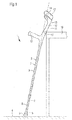
- a forearm crutch 1 consists of a support tube 2 with a contact surface 3 on the underside for support on a floor 4 or some other surface.
- the contact surface 3 is preferably part of a foot piece 5, which is designed, for example, as a cap made of rubber or a comparable material and is pushed onto the lower end of the support tube 2.
- the support tube 2 itself can either be formed in one piece or telescopically extendable.
- a height adjustment is provided, i.e. a possibility of locking the two tubes 6, 7 in different intermediate positions.
- a rasterized locking option can be implemented, for example, in that one of the two tubes 6, 7 - preferably the outer tube 7 - be designed with several bores at different heights, in which one on the other - preferably inner - tube 6 is radial guided pin pushed outwards by a spring can snap into place. By pushing this pin into the hole in question, the tubes 6, 7, which are initially locked into one another, can be displaced relative to one another and can then be locked together again in a new position by locking the pin into another hole.
- a stepless adjustment and / or locking option could be realized with a screw and / or clamping technique, whereby the interlocking ends of the two parts of the telescopic support tube 2 with interlocking threaded sections and / or with a clamping device could be designed to be adjustable and lockable with respect to one another .
- a plastic upper part 10 which is preferably designed as a molded part, in particular as an injection molded part, and has a shaft 11 that extends the support tube 2 upwards, with a handle 12 protruding laterally in the lower shaft area and one in the Forearm clamp 13 or cuff arranged in the upper shaft area for guiding reception of the forearm.
- the handle 12 usually points forward in the walking direction and can have an ergonomic design with troughs for each finger and / or be designed with a reflector at the front end.
- the handle 12 is preferably inclined slightly upwards towards the front, for example upwards at an angle of 10 ° to 30 ° with respect to the horizontal.
- the forearm clamp 13 can have two lateral legs 14 which embrace the forearm of the person concerned on both sides; a forearm cuff could be closed in the shape of a ring and therefore completely enclose the forearm of the person concerned.
- the shaft 11 of the plastic upper part 10 is preferably inclined slightly backwards with respect to the support tube 2, for example at an angle of 10 ° to 30 °.
- the plane spanned by the two legs 14 of the forearm cuff 13 or the plane spanned by the ring of a forearm cuff is preferably traversed vertically by the longitudinal axis of the shaft 11 of the plastic upper part 10, so that in particular the two legs 14 of the forearm cuff 13 are inclined upwards in the walking direction .
- a rear-facing reflector can also be located at the upper end of the forearm cuff 13 or cuff.
- the upper area of the rear side of the plastic upper part 10 facing away from the handle 12 facing in the walking direction serves as a contact surface 15 against a wall or a piece of furniture 16, in particular on an edge 17 thereof.
- the contact surface 15 ' is designed in a special way in order to prevent the forearm crutch 1' from falling over when leaning against a piece of furniture 16, in particular against a horizontal upper edge 17 of the same.
- a roll axis 18 is defined for this purpose, which connects the ground-side contact surface 3 with the center of gravity 19 of the forearm crutch 1 '. Since the center of gravity 19 is typically close to the longitudinal axis 8, 9 of the support tube 2, the roll axis 18 can coincide with that longitudinal axis 8, 9 or run at a small distance from it, in the latter case the roll axis 18 and the longitudinal axis 8, 9 of the support tube 2 meet or cut in the area of the contact surface 3.
- a height h is defined along the roll axis 18, the zero point of which is located at the point of contact between the contact surface 3 and the floor 4.
- the contact surface 15 ' preferably extends in the direction of the longitudinal coordinate h between a first height h 1 , where the (central) longitudinal axis of the handle 12 intersects the rear of the upper part 10, and a second height h 2 , where one of the (central) ) Longitudinal axes of the two side legs 14 of the forearm clamp 13 spanned plane intersects the rear side of the upper part 10.
- the contact surface 15 ′ it is also possible for the contact surface 15 ′ to extend over the entire height h of the rear side of the upper part 10.
- a cutting plane Q (h) is defined through the contact surface 15', which is perpendicularly penetrated by the roll axis 18 and contains the point of contact of the contact surface 15 'with the edge 17.
- the actual contact surface 15 ' can be limited by two lateral edge edges 20, the curvature radius of these edge edges 20 themselves can be relatively small, for example in the order of 1 mm to 20 mm.
- the cross-section through the contact surface 15 ′ within the cutting plane Q (h) follows a curve, in particular between the edge edges 20, which can be circumscribed by at least one circle that touches the curve in question in at least two contact points that are distant from one another, for example in the area of the two edge edges 20 .
- the largest circle K which can be rewritten to this curve, can degenerate into a straight line, which quasi corresponds to a circle with an infinitely large radius, provided that such a straight line still has two points of contact with the contact surface 15 'at a distance from one another.
- a prerequisite for a stable position of the forearm crutch 1 'on the edge 17 of the piece of furniture 16 is that within the cutting plane Q (h) the Distance v between the roll axis 18 and the edge 17 of the piece of furniture 16 or to the point of contact between the contact surface 15 'and the edge 17 of the piece of furniture 16 - if the forearm support 1' is oriented such that the handle 12 is maximally away from the edge 17 - is smaller than the radius R of the largest circle that can be rewritten around the contact surface 15 'at the relevant height h.
- the edge edges 20 can follow the course or the width of the plastic upper part 10 at the respective height h.
- the contact surface 15 ' would be narrower in the lower area of the plastic upper part 10 and wider in the upper area.
- Such a broadening can take place continuously or more in certain sections than in others.
- the widening takes place primarily in the upper area, i.e. approximately at the level of the forearm cuff 13.
- FIG. 4 A cross section through this closed contact surface 15 'is shown in FIG Fig. 4 to see. It can be seen that this surface has a convex curvature in cross-section.
- This cross-sectional convex curvature can follow a circular line K. or be approximated by a segment of a circular line K, the circular line K being defined by the position of its center point M and by its radius r.
- Fig. 4 the point of intersection P between the circular line K and the radius r was still connected to the point of intersection of the roll axis 18 through the relevant cutting plane; this connecting line is denoted by h.
- v specifies the distance between the roll axis 18 and the edge 17 of the piece of furniture, and thus also the height of the center of gravity of the forearm crutch 1 '.
- the center point M of the circular line K is always in front of the point of intersection of the roll axis 18 through the relevant section plane is located, in particular by a dimension d> 0, or even by a dimension d >> 0.
- the contact surface 15 ' can also have openings such as windows or gaps.
- the only criterion is that there are two spaced-apart points P on the circular line K, which can be connected to one another by a circular line K with a radius r, such that the radius r is greater than the distance d between the center M of the circular line K and the point of penetration of the roll axis 18 through the cutting plane.
- the contact surface 15 'in the upper region of the plastic upper part 10 of the forearm crutch 1' is displaced to the rear with respect to the roll axis 18, that is to say counter to the running direction.
- An effective countermeasure against such instability when the forearm crutch 1 'rests in the upper region of the contact surface 15' is either to add the radius of curvature r for the entire contact surface 15 'according to the position of the roll axis 18 in the uppermost region of the contact surface 15' Calculate so that the entire contact surface 15 'could then follow a cylinder jacket surface with a sufficiently large radius r, or choose the radius of curvature r not to be constant for the entire contact surface 15', but to adapt it to the position of the roll axis 18 at the relevant height ; the latter would then result in, for example, a conical contact surface 15 'which widens from bottom to top in accordance with a cone standing on the tip.
- the contact surface 15 ′′ has a trough-shaped or window-like recess 21 which is completely surrounded by the remaining part of the contact surface 15 ′′, similar to the self-contained frame of a window.
- the contact surface 15 (3) is interrupted by a slot-shaped, upwardly open notch 22, which is encompassed by the remaining part of the contact surface 15 ′′ similar to a U-shaped frame laterally and below.
- this slot-shaped notch 22 could be the contact surface 15 (3) even completely through, so that the contact surface 15 (3), characterized disintegrate in two separate halves.
- the center M is at infinity, and although this is not mandatory, it can be assumed with regard to the stability criterion according to the invention that this center M is infinitely wide is located in front of the roll axis 18, so such a connecting line fulfills the stability criterion.
- a division of the contact surface 15 ", 15 (3) as in the Figures 5 and 6th always fulfills this criterion, because a connecting line can always be found here which fulfills these requirements.
- the roll axis 18 can coincide with the longitudinal axis 8, 9 of the support tube 2 or preferably lie behind that longitudinal axis 8, 9, whereby the distance between the roll axis 18 and the edge 17 may be further reduced.
- This can be achieved in that the contact surface 15, 15 ', 15 ", 15 (3) is arranged on the rear side of a widening 23 of the plastic upper part 10, 10', 10", 10 (3) .
- the weight of this widening 23 shifts the center of gravity 19 to the rear, that is to say in the direction of the contact surface 15, 15 ', 15 ", 15 (FIG . 3).
- Such a widening 23 can optionally be integrated with the plastic upper part 10, 10 ', 10 ", 10 (3) or produced as a separate part that can be retrofitted to an existing forearm crutch 1, 1', 1", 1 (3) ,.
- the connection of such a separate widening part 23 to the plastic upper part 10, 10 ', 10 ", 10 (3) of the forearm crutch 1, 1', 1", 1 (3) can be effected in a variety of ways, e.g. using glue, a Velcro fastener, screws, etc.
- the actual contact surface 15, 15 ', 15 ", 15 (3) of the forearm crutch 1, 1', 1", 1 (3) can be made of a slip-resistant material or with a be provided with a slip-resistant covering, for example made of rubber or the like, and / or it can be provided with a slip-resistant structure, for example with a corrugation or corrugation, or with knobs, etc.
- a reflector can be provided on the back of the forearm crutch 1, 1', 1", 1 (3) , for example in a section above the contact surface 15, 15 ', 15 ", 15 (3) .
Landscapes
- Health & Medical Sciences (AREA)
- Epidemiology (AREA)
- Pain & Pain Management (AREA)
- Physical Education & Sports Medicine (AREA)
- Rehabilitation Therapy (AREA)
- Life Sciences & Earth Sciences (AREA)
- Animal Behavior & Ethology (AREA)
- General Health & Medical Sciences (AREA)
- Public Health (AREA)
- Veterinary Medicine (AREA)
- Rehabilitation Tools (AREA)
- Percussion Or Vibration Massage (AREA)
- Surgical Instruments (AREA)
- Control Of Motors That Do Not Use Commutators (AREA)
Applications Claiming Priority (1)
| Application Number | Priority Date | Filing Date | Title |
|---|---|---|---|
| DE202020000663.7U DE202020000663U1 (de) | 2020-02-18 | 2020-02-18 | Unterarmgehstütze |
Publications (2)
| Publication Number | Publication Date |
|---|---|
| EP3868352A1 true EP3868352A1 (fr) | 2021-08-25 |
| EP3868352B1 EP3868352B1 (fr) | 2023-01-18 |
Family
ID=74668602
Family Applications (1)
| Application Number | Title | Priority Date | Filing Date |
|---|---|---|---|
| EP21020078.8A Active EP3868352B1 (fr) | 2020-02-18 | 2021-02-17 | Cannes-béquilles |
Country Status (4)
| Country | Link |
|---|---|
| EP (1) | EP3868352B1 (fr) |
| DE (1) | DE202020000663U1 (fr) |
| ES (1) | ES2938323T3 (fr) |
| PL (1) | PL3868352T3 (fr) |
Citations (6)
| Publication number | Priority date | Publication date | Assignee | Title |
|---|---|---|---|---|
| DE20209938U1 (de) * | 2002-06-27 | 2002-08-29 | Dominique, Frank, 51674 Wiehl | Gehhilfe |
| DE10308044A1 (de) | 2003-02-26 | 2004-09-09 | Arwed Zöbisch | Standsichere Gehhilfe |
| DE202006010732U1 (de) | 2006-07-12 | 2006-10-19 | Mischker, Andrea | Überzug als Umfallhilfe für Unterarmgehstützen |
| FR2955764A1 (fr) * | 2010-02-02 | 2011-08-05 | Achille Paoli | Dispositif d'assistance a la marche |
| DE202016007561U1 (de) * | 2016-12-13 | 2017-01-12 | Thomas Haus | Standhilfe und Fixierung von Unterarmstützen an sekrechten Flächen |
| DE202018000154U1 (de) * | 2018-01-11 | 2018-05-30 | Michael Lenz | Stützenhalterung |
Family Cites Families (4)
| Publication number | Priority date | Publication date | Assignee | Title |
|---|---|---|---|---|
| DE7802345U1 (de) * | 1978-01-26 | 1978-06-01 | Ortopedia Gmbh, 2300 Kiel | Stuetzgriff fuer eine kruecke |
| CZ4893U1 (cs) * | 1996-05-09 | 1996-06-06 | Stanislav Ing. Maruszak | Berle předloketní |
| DE20309418U1 (de) * | 2003-01-20 | 2003-09-18 | Jung, Alfred H., 50935 Köln | Gehhilfe für Gehbehinderte |
| DE202005010241U1 (de) * | 2005-06-29 | 2006-11-02 | Jakob, Karl, Dipl.-Ing. (FH) Dr.h.c. | Gehhilfe |
-
2020
- 2020-02-18 DE DE202020000663.7U patent/DE202020000663U1/de active Active
-
2021
- 2021-02-17 EP EP21020078.8A patent/EP3868352B1/fr active Active
- 2021-02-17 PL PL21020078.8T patent/PL3868352T3/pl unknown
- 2021-02-17 ES ES21020078T patent/ES2938323T3/es active Active
Patent Citations (6)
| Publication number | Priority date | Publication date | Assignee | Title |
|---|---|---|---|---|
| DE20209938U1 (de) * | 2002-06-27 | 2002-08-29 | Dominique, Frank, 51674 Wiehl | Gehhilfe |
| DE10308044A1 (de) | 2003-02-26 | 2004-09-09 | Arwed Zöbisch | Standsichere Gehhilfe |
| DE202006010732U1 (de) | 2006-07-12 | 2006-10-19 | Mischker, Andrea | Überzug als Umfallhilfe für Unterarmgehstützen |
| FR2955764A1 (fr) * | 2010-02-02 | 2011-08-05 | Achille Paoli | Dispositif d'assistance a la marche |
| DE202016007561U1 (de) * | 2016-12-13 | 2017-01-12 | Thomas Haus | Standhilfe und Fixierung von Unterarmstützen an sekrechten Flächen |
| DE202018000154U1 (de) * | 2018-01-11 | 2018-05-30 | Michael Lenz | Stützenhalterung |
Also Published As
| Publication number | Publication date |
|---|---|
| PL3868352T3 (pl) | 2023-06-12 |
| ES2938323T3 (es) | 2023-04-10 |
| EP3868352B1 (fr) | 2023-01-18 |
| DE202020000663U1 (de) | 2021-05-19 |
Similar Documents
| Publication | Publication Date | Title |
|---|---|---|
| EP2152113B1 (fr) | Parasol à bras libre | |
| EP1325693A2 (fr) | Chaise | |
| DE69910410T2 (de) | Verstellbarer stuhl | |
| EP3100938B1 (fr) | Scooter | |
| EP3868352B1 (fr) | Cannes-béquilles | |
| EP0958763A1 (fr) | Support | |
| WO2013189489A1 (fr) | Chaise réglable en hauteur dotée d'une fonction de basculement | |
| EP1464849B1 (fr) | Appui télescopant réglable | |
| DE102020115651B4 (de) | Treppengehhilfevorrichtung zum Abstützen einer Person und zum (Um-)Positionieren und Getragen werden durch die Person jeweils beim Treppensteigen sowie deren Verwendung | |
| DE3342169A1 (de) | Tisch | |
| DE102008003671B4 (de) | Gepäckablage | |
| DE19808022A1 (de) | Verstellbares Pult | |
| DE2638924A1 (de) | Arbeitstisch mit integriertem stuhl | |
| DE102019122910B4 (de) | Gehhilfe mit Aufstelleinrichtung | |
| DE4406334C2 (de) | Zusammenklappbares Untergestell für einen Hocker, Stuhl oder Tisch | |
| DE202020103395U1 (de) | Treppengehhilfevorrichtung zum Abstützen einer Person und zum (Um-)Positionieren und Getragen werden durch die Person jeweils beim Treppensteigen sowie deren Verwendung | |
| DE1654631A1 (de) | Universaltisch | |
| EP1038465A2 (fr) | Support pour parapluie | |
| DE20010841U1 (de) | Gehhilfe | |
| WO2003006777A1 (fr) | Dispositif conçu pour stabiliser de maniere fiable des echelles ou des structures analogues | |
| DE4417270A1 (de) | Tisch bzw. Gestell mit wenigstens drei Standbeinen bzw. Standfüßen | |
| DE202011106262U1 (de) | Duschsitz | |
| DE4110586C2 (fr) | ||
| DE3828788A1 (de) | Schreib- oder arbeitstisch | |
| EP1068819A1 (fr) | Pupitre avec appui intégré pour les pieds |
Legal Events
| Date | Code | Title | Description |
|---|---|---|---|
| PUAI | Public reference made under article 153(3) epc to a published international application that has entered the european phase |
Free format text: ORIGINAL CODE: 0009012 |
|
| STAA | Information on the status of an ep patent application or granted ep patent |
Free format text: STATUS: THE APPLICATION HAS BEEN PUBLISHED |
|
| AK | Designated contracting states |
Kind code of ref document: A1 Designated state(s): AL AT BE BG CH CY CZ DE DK EE ES FI FR GB GR HR HU IE IS IT LI LT LU LV MC MK MT NL NO PL PT RO RS SE SI SK SM TR |
|
| STAA | Information on the status of an ep patent application or granted ep patent |
Free format text: STATUS: REQUEST FOR EXAMINATION WAS MADE |
|
| 17P | Request for examination filed |
Effective date: 20220224 |
|
| RBV | Designated contracting states (corrected) |
Designated state(s): AL AT BE BG CH CY CZ DE DK EE ES FI FR GB GR HR HU IE IS IT LI LT LU LV MC MK MT NL NO PL PT RO RS SE SI SK SM TR |
|
| RAP3 | Party data changed (applicant data changed or rights of an application transferred) |
Owner name: WEISS, RUPERT |
|
| RIN1 | Information on inventor provided before grant (corrected) |
Inventor name: WEISS, RUPERT |
|
| GRAP | Despatch of communication of intention to grant a patent |
Free format text: ORIGINAL CODE: EPIDOSNIGR1 |
|
| STAA | Information on the status of an ep patent application or granted ep patent |
Free format text: STATUS: GRANT OF PATENT IS INTENDED |
|
| INTG | Intention to grant announced |
Effective date: 20220920 |
|
| GRAS | Grant fee paid |
Free format text: ORIGINAL CODE: EPIDOSNIGR3 |
|
| GRAA | (expected) grant |
Free format text: ORIGINAL CODE: 0009210 |
|
| STAA | Information on the status of an ep patent application or granted ep patent |
Free format text: STATUS: THE PATENT HAS BEEN GRANTED |
|
| AK | Designated contracting states |
Kind code of ref document: B1 Designated state(s): AL AT BE BG CH CY CZ DE DK EE ES FI FR GB GR HR HU IE IS IT LI LT LU LV MC MK MT NL NO PL PT RO RS SE SI SK SM TR |
|
| REG | Reference to a national code |
Ref country code: GB Ref legal event code: FG4D Free format text: NOT ENGLISH |
|
| REG | Reference to a national code |
Ref country code: CH Ref legal event code: EP |
|
| REG | Reference to a national code |
Ref country code: DE Ref legal event code: R096 Ref document number: 502021000382 Country of ref document: DE |
|
| REG | Reference to a national code |
Ref country code: NL Ref legal event code: FP Ref country code: AT Ref legal event code: REF Ref document number: 1544297 Country of ref document: AT Kind code of ref document: T Effective date: 20230215 Ref country code: IE Ref legal event code: FG4D Free format text: LANGUAGE OF EP DOCUMENT: GERMAN |
|
| REG | Reference to a national code |
Ref country code: SE Ref legal event code: TRGR |
|
| REG | Reference to a national code |
Ref country code: ES Ref legal event code: FG2A Ref document number: 2938323 Country of ref document: ES Kind code of ref document: T3 Effective date: 20230410 |
|
| REG | Reference to a national code |
Ref country code: LT Ref legal event code: MG9D |
|
| P01 | Opt-out of the competence of the unified patent court (upc) registered |
Effective date: 20230501 |
|
| P02 | Opt-out of the competence of the unified patent court (upc) changed |
Effective date: 20230515 |
|
| PG25 | Lapsed in a contracting state [announced via postgrant information from national office to epo] |
Ref country code: RS Free format text: LAPSE BECAUSE OF FAILURE TO SUBMIT A TRANSLATION OF THE DESCRIPTION OR TO PAY THE FEE WITHIN THE PRESCRIBED TIME-LIMIT Effective date: 20230118 Ref country code: PT Free format text: LAPSE BECAUSE OF FAILURE TO SUBMIT A TRANSLATION OF THE DESCRIPTION OR TO PAY THE FEE WITHIN THE PRESCRIBED TIME-LIMIT Effective date: 20230518 Ref country code: NO Free format text: LAPSE BECAUSE OF FAILURE TO SUBMIT A TRANSLATION OF THE DESCRIPTION OR TO PAY THE FEE WITHIN THE PRESCRIBED TIME-LIMIT Effective date: 20230418 Ref country code: LV Free format text: LAPSE BECAUSE OF FAILURE TO SUBMIT A TRANSLATION OF THE DESCRIPTION OR TO PAY THE FEE WITHIN THE PRESCRIBED TIME-LIMIT Effective date: 20230118 Ref country code: LT Free format text: LAPSE BECAUSE OF FAILURE TO SUBMIT A TRANSLATION OF THE DESCRIPTION OR TO PAY THE FEE WITHIN THE PRESCRIBED TIME-LIMIT Effective date: 20230118 Ref country code: HR Free format text: LAPSE BECAUSE OF FAILURE TO SUBMIT A TRANSLATION OF THE DESCRIPTION OR TO PAY THE FEE WITHIN THE PRESCRIBED TIME-LIMIT Effective date: 20230118 |
|
| PG25 | Lapsed in a contracting state [announced via postgrant information from national office to epo] |
Ref country code: IS Free format text: LAPSE BECAUSE OF FAILURE TO SUBMIT A TRANSLATION OF THE DESCRIPTION OR TO PAY THE FEE WITHIN THE PRESCRIBED TIME-LIMIT Effective date: 20230518 Ref country code: GR Free format text: LAPSE BECAUSE OF FAILURE TO SUBMIT A TRANSLATION OF THE DESCRIPTION OR TO PAY THE FEE WITHIN THE PRESCRIBED TIME-LIMIT Effective date: 20230419 Ref country code: FI Free format text: LAPSE BECAUSE OF FAILURE TO SUBMIT A TRANSLATION OF THE DESCRIPTION OR TO PAY THE FEE WITHIN THE PRESCRIBED TIME-LIMIT Effective date: 20230118 |
|
| REG | Reference to a national code |
Ref country code: DE Ref legal event code: R097 Ref document number: 502021000382 Country of ref document: DE Ref country code: BE Ref legal event code: MM Effective date: 20230228 |
|
| PG25 | Lapsed in a contracting state [announced via postgrant information from national office to epo] |
Ref country code: SM Free format text: LAPSE BECAUSE OF FAILURE TO SUBMIT A TRANSLATION OF THE DESCRIPTION OR TO PAY THE FEE WITHIN THE PRESCRIBED TIME-LIMIT Effective date: 20230118 Ref country code: RO Free format text: LAPSE BECAUSE OF FAILURE TO SUBMIT A TRANSLATION OF THE DESCRIPTION OR TO PAY THE FEE WITHIN THE PRESCRIBED TIME-LIMIT Effective date: 20230118 Ref country code: MC Free format text: LAPSE BECAUSE OF FAILURE TO SUBMIT A TRANSLATION OF THE DESCRIPTION OR TO PAY THE FEE WITHIN THE PRESCRIBED TIME-LIMIT Effective date: 20230118 Ref country code: LU Free format text: LAPSE BECAUSE OF NON-PAYMENT OF DUE FEES Effective date: 20230217 Ref country code: EE Free format text: LAPSE BECAUSE OF FAILURE TO SUBMIT A TRANSLATION OF THE DESCRIPTION OR TO PAY THE FEE WITHIN THE PRESCRIBED TIME-LIMIT Effective date: 20230118 Ref country code: DK Free format text: LAPSE BECAUSE OF FAILURE TO SUBMIT A TRANSLATION OF THE DESCRIPTION OR TO PAY THE FEE WITHIN THE PRESCRIBED TIME-LIMIT Effective date: 20230118 Ref country code: CZ Free format text: LAPSE BECAUSE OF FAILURE TO SUBMIT A TRANSLATION OF THE DESCRIPTION OR TO PAY THE FEE WITHIN THE PRESCRIBED TIME-LIMIT Effective date: 20230118 |
|
| PLBE | No opposition filed within time limit |
Free format text: ORIGINAL CODE: 0009261 |
|
| STAA | Information on the status of an ep patent application or granted ep patent |
Free format text: STATUS: NO OPPOSITION FILED WITHIN TIME LIMIT |
|
| PG25 | Lapsed in a contracting state [announced via postgrant information from national office to epo] |
Ref country code: SK Free format text: LAPSE BECAUSE OF FAILURE TO SUBMIT A TRANSLATION OF THE DESCRIPTION OR TO PAY THE FEE WITHIN THE PRESCRIBED TIME-LIMIT Effective date: 20230118 |
|
| REG | Reference to a national code |
Ref country code: IE Ref legal event code: MM4A |
|
| 26N | No opposition filed |
Effective date: 20231019 |
|
| PG25 | Lapsed in a contracting state [announced via postgrant information from national office to epo] |
Ref country code: SI Free format text: LAPSE BECAUSE OF FAILURE TO SUBMIT A TRANSLATION OF THE DESCRIPTION OR TO PAY THE FEE WITHIN THE PRESCRIBED TIME-LIMIT Effective date: 20230118 Ref country code: IE Free format text: LAPSE BECAUSE OF NON-PAYMENT OF DUE FEES Effective date: 20230217 |
|
| PG25 | Lapsed in a contracting state [announced via postgrant information from national office to epo] |
Ref country code: BE Free format text: LAPSE BECAUSE OF NON-PAYMENT OF DUE FEES Effective date: 20230228 |
|
| PGFP | Annual fee paid to national office [announced via postgrant information from national office to epo] |
Ref country code: NL Payment date: 20240222 Year of fee payment: 4 Ref country code: ES Payment date: 20240301 Year of fee payment: 4 |
|
| PGFP | Annual fee paid to national office [announced via postgrant information from national office to epo] |
Ref country code: DE Payment date: 20240131 Year of fee payment: 4 Ref country code: CH Payment date: 20240301 Year of fee payment: 4 |
|
| PGFP | Annual fee paid to national office [announced via postgrant information from national office to epo] |
Ref country code: SE Payment date: 20240222 Year of fee payment: 4 Ref country code: PL Payment date: 20240208 Year of fee payment: 4 Ref country code: IT Payment date: 20240229 Year of fee payment: 4 Ref country code: FR Payment date: 20240227 Year of fee payment: 4 |