EP3868329B1 - Implantatanalog - Google Patents
Implantatanalog Download PDFInfo
- Publication number
- EP3868329B1 EP3868329B1 EP21161587.7A EP21161587A EP3868329B1 EP 3868329 B1 EP3868329 B1 EP 3868329B1 EP 21161587 A EP21161587 A EP 21161587A EP 3868329 B1 EP3868329 B1 EP 3868329B1
- Authority
- EP
- European Patent Office
- Prior art keywords
- abutment
- contact surface
- analog
- implant
- prosthesis
- Prior art date
- Legal status (The legal status is an assumption and is not a legal conclusion. Google has not performed a legal analysis and makes no representation as to the accuracy of the status listed.)
- Active
Links
- 239000007943 implant Substances 0.000 title claims description 333
- 239000004053 dental implant Substances 0.000 claims description 33
- 230000000295 complement effect Effects 0.000 claims description 20
- 238000004873 anchoring Methods 0.000 claims description 19
- 210000000988 bone and bone Anatomy 0.000 claims description 16
- 230000001419 dependent effect Effects 0.000 claims 2
- 239000004568 cement Substances 0.000 description 36
- 210000003128 head Anatomy 0.000 description 28
- 210000000214 mouth Anatomy 0.000 description 19
- 239000000463 material Substances 0.000 description 8
- MCMNRKCIXSYSNV-UHFFFAOYSA-N Zirconium dioxide Chemical compound O=[Zr]=O MCMNRKCIXSYSNV-UHFFFAOYSA-N 0.000 description 6
- 238000004519 manufacturing process Methods 0.000 description 6
- 241000894006 Bacteria Species 0.000 description 5
- 238000011065 in-situ storage Methods 0.000 description 5
- 230000010485 coping Effects 0.000 description 4
- 238000000034 method Methods 0.000 description 4
- 230000004308 accommodation Effects 0.000 description 3
- 230000009286 beneficial effect Effects 0.000 description 3
- 238000010883 osseointegration Methods 0.000 description 3
- 238000007789 sealing Methods 0.000 description 3
- 210000004872 soft tissue Anatomy 0.000 description 3
- RTAQQCXQSZGOHL-UHFFFAOYSA-N Titanium Chemical compound [Ti] RTAQQCXQSZGOHL-UHFFFAOYSA-N 0.000 description 2
- 239000002253 acid Substances 0.000 description 2
- 239000000919 ceramic Substances 0.000 description 2
- 238000005530 etching Methods 0.000 description 2
- 238000011066 ex-situ storage Methods 0.000 description 2
- 238000003780 insertion Methods 0.000 description 2
- 230000037431 insertion Effects 0.000 description 2
- 238000002955 isolation Methods 0.000 description 2
- 239000011505 plaster Substances 0.000 description 2
- 238000005488 sandblasting Methods 0.000 description 2
- 210000001519 tissue Anatomy 0.000 description 2
- 229910052719 titanium Inorganic materials 0.000 description 2
- 239000010936 titanium Substances 0.000 description 2
- 208000037408 Device failure Diseases 0.000 description 1
- 239000004696 Poly ether ether ketone Substances 0.000 description 1
- 229910001069 Ti alloy Inorganic materials 0.000 description 1
- QCWXUUIWCKQGHC-UHFFFAOYSA-N Zirconium Chemical compound [Zr] QCWXUUIWCKQGHC-UHFFFAOYSA-N 0.000 description 1
- 229910045601 alloy Inorganic materials 0.000 description 1
- 239000000956 alloy Substances 0.000 description 1
- 238000000149 argon plasma sintering Methods 0.000 description 1
- JUPQTSLXMOCDHR-UHFFFAOYSA-N benzene-1,4-diol;bis(4-fluorophenyl)methanone Chemical compound OC1=CC=C(O)C=C1.C1=CC(F)=CC=C1C(=O)C1=CC=C(F)C=C1 JUPQTSLXMOCDHR-UHFFFAOYSA-N 0.000 description 1
- 230000005540 biological transmission Effects 0.000 description 1
- 239000007767 bonding agent Substances 0.000 description 1
- 238000005266 casting Methods 0.000 description 1
- 229910010293 ceramic material Inorganic materials 0.000 description 1
- 239000011248 coating agent Substances 0.000 description 1
- 238000000576 coating method Methods 0.000 description 1
- 230000003247 decreasing effect Effects 0.000 description 1
- 210000004513 dentition Anatomy 0.000 description 1
- 201000010099 disease Diseases 0.000 description 1
- 208000037265 diseases, disorders, signs and symptoms Diseases 0.000 description 1
- 208000015181 infectious disease Diseases 0.000 description 1
- 238000005495 investment casting Methods 0.000 description 1
- 230000007774 longterm Effects 0.000 description 1
- 229910052751 metal Inorganic materials 0.000 description 1
- 239000002184 metal Substances 0.000 description 1
- 239000007769 metal material Substances 0.000 description 1
- 230000004048 modification Effects 0.000 description 1
- 238000012986 modification Methods 0.000 description 1
- 238000010111 plaster casting Methods 0.000 description 1
- 229920002530 polyetherether ketone Polymers 0.000 description 1
- 229920000642 polymer Polymers 0.000 description 1
- 230000003014 reinforcing effect Effects 0.000 description 1
- 125000006850 spacer group Chemical group 0.000 description 1
- 239000010935 stainless steel Substances 0.000 description 1
- 229910001220 stainless steel Inorganic materials 0.000 description 1
- 238000004381 surface treatment Methods 0.000 description 1
- 230000036346 tooth eruption Effects 0.000 description 1
- 229910052727 yttrium Inorganic materials 0.000 description 1
- VWQVUPCCIRVNHF-UHFFFAOYSA-N yttrium atom Chemical compound [Y] VWQVUPCCIRVNHF-UHFFFAOYSA-N 0.000 description 1
- 229910052726 zirconium Inorganic materials 0.000 description 1
Images


Classifications
-
- A—HUMAN NECESSITIES
- A61—MEDICAL OR VETERINARY SCIENCE; HYGIENE
- A61C—DENTISTRY; APPARATUS OR METHODS FOR ORAL OR DENTAL HYGIENE
- A61C8/00—Means to be fixed to the jaw-bone for consolidating natural teeth or for fixing dental prostheses thereon; Dental implants; Implanting tools
- A61C8/0048—Connecting the upper structure to the implant, e.g. bridging bars
- A61C8/005—Connecting devices for joining an upper structure with an implant member, e.g. spacers
- A61C8/0059—Connecting devices for joining an upper structure with an implant member, e.g. spacers with additional friction enhancing means
-
- A—HUMAN NECESSITIES
- A61—MEDICAL OR VETERINARY SCIENCE; HYGIENE
- A61C—DENTISTRY; APPARATUS OR METHODS FOR ORAL OR DENTAL HYGIENE
- A61C8/00—Means to be fixed to the jaw-bone for consolidating natural teeth or for fixing dental prostheses thereon; Dental implants; Implanting tools
- A61C8/0001—Impression means for implants, e.g. impression coping
-
- A—HUMAN NECESSITIES
- A61—MEDICAL OR VETERINARY SCIENCE; HYGIENE
- A61C—DENTISTRY; APPARATUS OR METHODS FOR ORAL OR DENTAL HYGIENE
- A61C8/00—Means to be fixed to the jaw-bone for consolidating natural teeth or for fixing dental prostheses thereon; Dental implants; Implanting tools
- A61C8/0048—Connecting the upper structure to the implant, e.g. bridging bars
- A61C8/005—Connecting devices for joining an upper structure with an implant member, e.g. spacers
- A61C8/0054—Connecting devices for joining an upper structure with an implant member, e.g. spacers having a cylindrical implant connecting part
-
- A—HUMAN NECESSITIES
- A61—MEDICAL OR VETERINARY SCIENCE; HYGIENE
- A61C—DENTISTRY; APPARATUS OR METHODS FOR ORAL OR DENTAL HYGIENE
- A61C8/00—Means to be fixed to the jaw-bone for consolidating natural teeth or for fixing dental prostheses thereon; Dental implants; Implanting tools
- A61C8/0048—Connecting the upper structure to the implant, e.g. bridging bars
- A61C8/005—Connecting devices for joining an upper structure with an implant member, e.g. spacers
- A61C8/0066—Connecting devices for joining an upper structure with an implant member, e.g. spacers with positioning means
-
- A—HUMAN NECESSITIES
- A61—MEDICAL OR VETERINARY SCIENCE; HYGIENE
- A61C—DENTISTRY; APPARATUS OR METHODS FOR ORAL OR DENTAL HYGIENE
- A61C8/00—Means to be fixed to the jaw-bone for consolidating natural teeth or for fixing dental prostheses thereon; Dental implants; Implanting tools
- A61C8/0093—Features of implants not otherwise provided for
-
- A—HUMAN NECESSITIES
- A61—MEDICAL OR VETERINARY SCIENCE; HYGIENE
- A61C—DENTISTRY; APPARATUS OR METHODS FOR ORAL OR DENTAL HYGIENE
- A61C9/00—Impression cups, i.e. impression trays; Impression methods
- A61C9/004—Means or methods for taking digitized impressions
- A61C9/0046—Data acquisition means or methods
Definitions
- the invention relates to a dental implant system comprising a dental implant and an associated implant analog, the analog forming a discontinuous surface to allow for drainage of a bonding agent applied to the prosthetic element, as is defined in detail in the claims.
- Dental implants are used to replace individual teeth or for anchoring more complex structures, which generally replace several or even all of the teeth.
- the materials used for dental implants are often titanium and alloys thereof and increasingly ceramic. These materials have the necessary strength for withstanding the mechanical loads that occur, and they are at the same time sufficiently biocompatible for osseointegration and long term use in the mouth.
- Implants have two essential parts: an anchoring part and an abutment part.
- the anchoring part is embedded in the bone, where it osseointegrates with the bone tissue to provide a firm anchor for the prosthesis.
- the abutment extends into the oral cavity and provides a core support for the prosthesis.
- the desired prosthetic element e.g. bridge or crown
- the implant can be constructed in one part, such that the anchoring part and abutment part are produced in one integral, monolithic piece. Hence, in such implant systems, the integrated anchoring part and abutment are always positioned within the mouth at the same time and the single piece implant extends into the oral cavity to form a core support for the prosthesis.
- implants are often constructed in two or more parts, in which case they consist of at least an anchoring component, often referred to in isolation as the implant, and a separate abutment, sometimes referred to as a spacer, or post.
- the anchoring component is usually either embedded completely in the bone, that is to say to the height of the alveolar crest, and is thus often referred to as a "bone level” implant” or protrudes by a few millimetres from the alveolar crest into the soft tissue, often known as a "tissue level” implant.
- the abutment is mounted either directly or indirectly to the anchoring component after the latter has become incorporated (osseointegrated) into the bone or directly after the anchoring component has been inserted. It can also be attached to the anchoring component prior to insertion. Most usually however the abutment is not mounted until after osseointegration.
- multi-part implants are more versatile, because the anchoring part and the abutment can be adapted to individual requirements.
- the abutment shape and angulation, relative to the anchoring part can be selected after implant insertion. This provides the surgeon with more flexibility and room for error in the placement of the implant.
- An additional advantage of multi-part implants is that the abutment can be made from a different material than the anchoring part.
- implant will be used to denote the anchoring component of a multi-part implant, namely, the element which in use is anchored within the bone
- abutment will be used to denote a separate component which in use is connected, either directly or indirectly, to the implant and extends into the oral cavity to provide core support to a dental prosthesis.
- An implant analog is a piece used to replicate the dental implant in a physical model of the patient's mouth.
- Such models are models of the oral cavity or parts of the oral cavity which may be obtained, for example, by traditional plaster casting or by laser sintering or the like making use of CAD data of patients.
- the resulting model, complete with implant analog can be used by a dental technician to create a patient specific prosthesis for attachment to the implant already in situ within the patient's mouth.
- the abutment is fastened to the analog, and in some cases modified, and the prosthesis is built up and shaped on top of this, using one of several known methods, e.g. lost-wax casting, veneering or casting onto a stock or custom coping, direct veneering onto the abutment etc.
- Known implant analogs comprise an essentially identical reconstruction of the coronal end of the implant, including the abutment connection geometry, which enables the abutment to be fixedly connected to the implant, and the coronal end surface(s) of the implant.
- the coronal end of the implant usually comprises at least one coronally facing planar or tapered shoulder having a smooth, continuous surface for contact with the prosthesis and/or abutment.
- this surface is circular symmetric about the longitudinal axis of the implant, although implants are also known which have a scalloped or slanted coronal end, i.e. a coronal end surface whose height undulates or otherwise changes about the longitudinal axis in order to more exactly follow the bone or soft tissue contour.
- the smooth, continuous nature of the shoulder provides a contact surface against which the prosthesis and/or abutment can abut around the whole circumference of the components, thus enabling good force transmission between them as well as creating a seal against bacteria.
- the associated analog replicates the coronal end surface(s) of the implant such that the abutment can be placed in equivalent contact with the analog during the creation of the prosthesis and so that, when the prosthesis is intended to contact the implant, the prosthesis can be designed to sit flush on the implant surface.
- the apical end of the implant analog typically differs from the apical end of the implant and is shaped for fixation (either permanent or removable) within the model.
- the material used to make the analog can also vary from the implant.
- the analog is also not subject to any surface treatment, such as sandblasting or acid etching, which the implant may undergo in order to improve osseointergration.
- the abutment and prosthesis are attached to the implant. Depending on the design of the implant system and dentist preference, this can be achieved in several ways. Sometimes the abutment will be screwed to the implant, either directly, or more usually indirectly using a separate screw. Alternatively, the abutment can be cemented to the implant. The prosthesis can also either be cemented or screwed to the abutment, either before or after the abutment is connected to the implant.
- FIGs. 1A and B An illustration of this problem is shown in FIGs. 1A and B .
- an abutment 20 is attached to an implant analog 10 ( FIG. 1A ).
- the analog contains an identical reproduction of the abutment connection geometry, including planar coronally facing shoulder 108 of an implant 1.
- the abutment comprises an annular shoulder 21 which abuts the inner area of the analog shoulder 18.
- the outer area of the shoulder 18 is covered by the prosthesis 30.
- the prosthesis 30 is glued to the abutment 20. During this process, cement will often spill out from the join between abutment 20 and prosthesis 30 and form a layer between the analog shoulder 18 and the lower edge of the prosthesis. This means that the prosthesis does not sit flush on the analog shoulder.
- the abutment 20 and prosthesis 30 are removed from the analog 10 and placed on the implant 1, already in situ within the patient's mouth ( Fig. 1B ). If all, or a part, of the cement layer formed between the prosthesis and analog remains on the analog when the abutment/prosthesis unit is removed, then when the prosthesis is placed on the implant 1 a gap G, exaggerated for explanation purposes, will exist between the prosthesis 30 and the coronally facing shoulder 108 of the implant 1.
- the present invention seeks to ensure a flush connection between the contacting surfaces of an implant and a final prosthesis prepared ex-situ.
- the invention relates to a dental implant system comprising a dental implant (1) and an associated implant analog (50),
- the surface of the analog which is arranged for contact with the prosthesis is shaped such that it contacts the prosthesis at only a few supporting points. This creates a discontinuous contact between the analog and the prosthesis.
- the prosthesis contact surface of the analog therefore provides support for the prosthesis while the discontinuities in the surface enable any cement overflow to drain away, rather than forming the problematic cement layer described above.
- the discontinuous points of contact provided by the prosthesis contact surface of the analog enable the prosthesis to be positioned and cemented correctly on the abutment such that the prosthesis will sit flush on the prosthesis contact surface of the implant.
- the prosthesis contact surface of the analog is discontinuous in the circumferential and/or radial direction.
- the analog has a modified prosthesis contact surface relative to the implant.
- the discontinuous prosthesis contact surface of the analog matches the prosthesis contact surface of the associated implant.
- match it is meant that the points making up the discontinuous prosthesis contact surface of the analog are identical to points on the continuous prosthesis contact surface of the implant, relative to the abutment contact surface and longitudinal axis of each component.
- the prosthesis contact surface of the analog has the same longitudinal cross-section as the prosthesis contact surface of the implant at the same location when measured relative to the abutment contact surfaces and longitudinal axes of each component. This ensures that a prosthesis which lies flush on the discontinuous prosthesis contact surface of the analog will also lie flush on the continuous prosthesis contact surface of the implant when the bonded abutment-prosthesis unit is transferred to the implant.
- the abutment contact surface of the analog matches at least a portion of the abutment contact surface of the implant about the entire circumference of the analog.
- matches in this case it is meant that the points making up the abutment contact surface of the analog are identical to points on the abutment contact surface of the implant, relative to the longitudinal axis of each component.
- the abutment contact surface of the analog has the same longitudinal cross-section as the abutment contact surface of the implant at the same radial location as measured relative to the longitudinal axis of the each component.
- the abutment contact surface of the analog matches the abutment contact surface of the implant about the entire circumference of the analog, the abutment contact surface of the analog is therefore continuous in the circumferential direction. While the abutment contact surface of the analog matches the abutment contact surface of the implant about its entire circumference, it is not necessary for the abutment contact surface to match the entire abutment contact surface of the implant, i.e., the two surfaces may have different radial extents. However, preferably the abutment contact surface of the analog matches the entire abutment contact surface of the implant.
- apical refers to the direction towards the bone and “coronal” to the direction towards the teeth. Therefore the apical end of a component is the end which, in use, is directed towards the jaw bone and the coronal end is that which is directed towards the oral cavity. In relation to an analog, or any other component which is not located in the mouth but is used in a model of the mouth, these terms refer to the ends of the component directed towards the modelled jaw bone and teeth (oral cavity) respectively.
- coronally facing it is meant that the surface in question extends in the radial direction, i.e. it has a radial dimension, and faces the coronal end of the component such that this is visible when the component is viewed from the coronal end.
- the surface can extend perpendicular to the longitudinal axis of the component or may slope in the coronal or apical direction relative to this. Coronally facing surfaces therefore provide stop surfaces against which a second component, placed onto the component from the coronal end, can rest.
- the implant comprises abutment connection geometry which comprises a coronally facing abutment contact surface.
- the abutment contact surface of the implant is located radially inwards of the prosthesis contact surface and provides a stop for defining the axial location of an abutment relative to the implant.
- the abutment contact surface of the implant is continuous in the circumferential direction. This provides a firm, closed stop surface for the abutment to rest upon in use, thus enabling force to be transmitted to the implant, and providing a seal against bacteria.
- the associated analog comprises an abutment contact surface which matches the abutment contact surface of the implant about the whole circumference of the analog.
- This provides a firm stop surface for the abutment to rest upon in use which matches the abutment contact surface of the implant. This ensures that the abutment sits on the analog in the same position, relative to the prosthesis contact surface, as on the implant. The fact that this surface is continuous prevents any tilting of the abutment and also avoids cement overspill from extending radially inwards, where it could interfere with other elements of the abutment connection geometry.
- the implant and associated analog of the present invention are therefore intended for use in combination with an abutment, which is designed to contact the abutment contact surface of both the implant and analog.
- the discontinuous prosthesis contact surface of the analog assists the user in precisely bonding a prosthesis to the abutment in a manner which will ensure flush contact with the implant.
- the system further comprises an abutment having an apical portion and a coronal portion, at least the apical portion extending along a longitudinal axis, the apical portion comprising connection geometry for cooperation with the abutment connection geometry of the implant and analog, such that the abutment can be seated in the same one or more defined position on both the implant and abutment, said connection geometry comprising an apically facing contact surface complementary to the abutment contact surfaces of the implant and analog for directly contacting said abutment contact surfaces to define the axial location of the abutment relative to the implant and analog, said apically facing contact surface being continuous in the circumferential direction, wherein, when the abutment is seated on the implant, the contact surface of the abutment contacts the abutment contact surface of the implant about the entire circumference of the implant, the abutment being located radially inwards of the prosthesis contact surface such that this surface remains exposed, and when the abutment is seated
- apically facing it is meant that the surface in question extends in the radial direction, i.e. it has a radial dimension, and faces the apical end of the component such that this is visible when the component is viewed from the apical end.
- the surface can extend perpendicular to the longitudinal axis of the component or may slope in the coronal or apical direction relative to this. Apically facing surfaces therefore provide stop surfaces which, when the component is placed onto a second component from the coronal end, can abut coronally facing surfaces of the second component.
- both the abutment contact surface of the analog and apically facing contact surface of the abutment are continuous in the circumferential direction wherein, when the abutment is seated on the analog, the two surfaces contact one another about the entire circumference of the analog such that a circumferentially closed contact is formed between the components.
- the surfaces are sized and shaped such that, when the abutment is seated on the analog, the outermost radial edges of the surfaces are in alignment.
- the apically facing contact surface can extend slightly radially beyond the abutment contact surface of the analog, as any cement overspill onto the underside of the abutment can be removed prior to connection to the implant.
- the abutment contact surface of the analog can extend slightly radially beyond the apically facing contact surface. In such embodiments however the prosthesis should be designed such that this does not contact the exposed area of the abutment contact surface of the analog.
- the coronal portion of the abutment of the present invention is preferably intended for connection to a dental prosthesis.
- the coronal portion can extend along the same longitudinal axis as the apical portion or may be angled relative to this.
- the coronal portion comprises anti-rotation means on its external surface for cooperation with complementary anti-rotation means formed in a cavity of a dental prosthesis.
- the implant and associated analog comprise abutment contact surfaces which match one another about the circumference of the components.
- the abutment contact surface of implant, and hence also the abutment contact surface of the analog is preferably linear in all longitudinal cross-sections, i.e. in all planes containing the longitudinal axis of the implant or analog respectively.
- Such a surface makes it easier to design and manufacture the complementary apically facing contact surface of the abutment.
- the linear longitudinal cross-section is constant about the longitudinal axis of the implant or analog respectively.
- implants are known whose coronal ends are scalloped or slanted. It is possible therefore for the axial height of the abutment contact surface of the implant, and hence also the abutment contact surface of the analog, to vary about the longitudinal axis of the implant or analog respectively, so as to create a scalloped or slanted surface.
- the longitudinal cross-section of the abutment contact surface of both the implant and analog may alter about the longitudinal axis.
- the longitudinal cross-section of the abutment contact surface may change from horizontal to tapering towards or away from the axis and back to horizontal as the surface undulates around the axis.
- the cross-section may be tapered about the whole circumference of the implant, and hence associated analog, but the degree of taper may differ.
- the abutment contact surface of the implant, and hence also the abutment contact surface of the associated analog is circular symmetric about the longitudinal axis of the implant and analog respectively.
- this surface also comprises a linear longitudinal cross-section, such that the abutment contact surface of the implant, and hence associated analog, is perpendicular to the longitudinal axis or slopes in a coronal or apical direction to this, so as to form a conical or frustoconical surface.
- the apically facing contact surface of the abutment of a preferred embodiment of the present invention is complementary to the abutment contact surfaces of the implant and analog, and therefore this surface can be similarly scalloped, slanted or comprise a linear longitudinal cross-section that alters about the circumference of the abutment, as required.
- the apically facing contact surface of the abutment is circular symmetric and comprises a linear longitudinal cross-section.
- the prosthesis contact surface of the implant is preferably linear in all longitudinal cross-sections.
- Such a surface makes it easier to design and manufacture a complementary surface of the prosthesis for contacting the prosthesis contact surface.
- the linear cross-section is constant about the axis of the implant and analog respectively.
- the prosthesis contact surface of the implant is circular symmetric about the longitudinal axis of the implant and analog respectively.
- this surface also comprises a linear longitudinal cross-section, such that the prosthesis contact surface of the implant, and hence associated analog, is perpendicular to the longitudinal axis or slopes in a coronal or apical direction to this, so as to form a conical or frustoconical surface.
- the analog head comprises a sidewall extending apically from the radially outer edge of the abutment contact surface, said plurality of circumferentially spaced struts or one or more annular strut extending radially and axially from said side wall.
- This increases the depth of the gaps located between the struts and/or the strut and the abutment contact surface, thus facilitating the drainage of cement.
- each strut may comprise one or more transverse grooves in its coronal end, the grooves being formed at equal or varying radial distances in each strut.
- the entire coronal end of each strut matches the prosthesis contact surface of the associated implant and thus forms the discontinuous prosthesis contact surface of the analog.
- the tapered surfaces of the strut(s) help to direct any cement overspill away from the prosthesis.
- the struts are "roof shaped".
- the opposing sides of each strut taper evenly inwards towards one another in the coronal direction to create a central ridge, said ridge forming the discontinuous prosthesis contact surface.
- annular strut When one or more annular strut is used, support is provided for the prosthesis about the whole circumference of the analog. This is beneficial as it prevents any tilting of the prosthesis out of the plane of the prosthesis contact surface.
- a plurality of radially spaced annular struts is provided, most preferably between two and four radially spaced struts. Preferably these struts are equally spaced in the radial direction. Providing multiple annular struts ensures that the prosthesis is supported across its radial thickness and thus ensures a flush fit across the radial width of the prosthesis contact surface of the associated implant.
- the prosthesis contact surface of the analog is formed by the coronal end of a plurality of circumferentially spaced struts such that the prosthesis contact surface is discontinuous at least in the circumferential direction.
- the abutment connection geometry of the implant and associated analog can comprise further features.
- the analog of the present invention is designed such that an abutment can be seated on the analog in the same one or more defined position as it can on the implant, the abutment connection geometry of the analog will match the features of the abutment connection geometry of the implant, in the same location in relation to the abutment contact surface, to at least the extent necessary in order to enable this to occur.
- any abutment designed for connection to the implant can also be connected to the associated analog of the present invention in an identical manner.
- the apical portion of the associated abutment may comprise an apically extending portion for accommodation within the blind bore of the implant and analog and, coronally adjacent to and surrounding said apically extending portion, an apically facing contact surface, this surface being preferably perpendicular to the longitudinal axis of the apical portion.
- anti-rotation means which prevent relative rotation between the implant and abutment and which set a finite number of rotational positions which the abutment can have relative to the implant.
- anti-rotation means ensure that the exact angular position of the abutment relative to the implant is known prior to final fixation of these components. This is beneficial, particularly when the implant system is intended to support a single tooth prosthesis (crown), as it can ensure correct alignment of the prosthesis with the surrounding teeth.
- anti-rotation means can help prevent loosening of the abutment during the lifetime of the implant.
- anti-rotation means consist of complementary non-circular symmetric portions in the implant and abutment, usually having a polygonal shape such as a hexagon or octagon.
- an internal bore of the implant may comprise a section having a hexagonal cross-section, while the abutment comprises a portion having an equivalent hexagonal cross-section.
- the implant may comprise a male polygonal boss protruding from its coronal end, which in use is accommodated within a correspondingly shaped polygonal cavity within the abutment.
- connection geometry of the preferred associated abutment preferably comprises anti-rotation means having a non-circular symmetric cross-section in a plane perpendicular to the longitudinal axis of the apical portion, said anti-rotation means being complementary to the anti-rotation means of the implant and analog such that the abutment can be seated on each component in the same one or more defined angular position. It is possible however for the connection geometry of the abutment to alternatively comprise a circular symmetric portion that can be accommodated by or accommodate the anti-rotation means of the implant and associated analog.
- the anti-rotation means of the implant and analog and hence also the complementary anti-rotation means of the abutment, where present, can take the form of any anti-rotation means known in the art.
- the anti-rotation means may have a polygonal cross-section or comprise a number of circumferentially spaced protrusions and/or grooves.
- the anti-rotation means of the implant and associated analog has a cross-section with four-fold rotational symmetry, such that an abutment having complementary anti-rotation means can be placed in four discrete angular orientations relative to the implant and analog respectively.
- the anti-rotation means has a square cross-section, most preferably with rounded corners.
- the struts can be used to scrape off any cement residue from the underside of the prosthesis by rotating the abutment and prosthesis relative to the analog.
- anti-rotation means are present on the analog and abutment. Due to manufacturing tolerances, all anti-rotation connections between dental implant components will allow some small degree of rotational play between the components. While it is generally desired to keep such play to a minimum, the present invention has also utilised this necessary inaccuracy between the anti-rotation means of the analog and abutment in order to assist with the removal of overspill cement.
- the width of the coronal end of each circumferentially spaced strut is less than the width of the arc of rotational play between the analog and abutment.
- the abutment can be "wiggled" clockwise and anti-clockwise such that the underside of the prosthesis is scraped back and forth against the struts of the prosthesis contact surface. This removes any cement layer which may have formed between the underside of the prosthesis and the discontinuous prosthesis contact surface.
- the implant, and hence the associated analog comprise an anti-rotation means having an n-fold symmetry
- the prosthesis contact surface of the analog is discontinuous in the circumferential direction
- the prosthesis contact surface of the analog comprises n or 2n evenly circumferentially spaced struts. This symmetry increases the precision of the attachment of the prosthesis by preventing or limiting tilting of the prosthesis during bonding, which can occur if large gaps are left between the circumferentially spaced struts.
- the implant and hence the associated analog, comprises a coronally facing prosthesis contact surface.
- the prosthesis contact surface of the implant, and hence associated analog is located radially beyond the abutment contact surface, i.e. on the radially outer side of the abutment contact surface. This is because, in use, the prosthesis will be placed over the abutment, and hence the prosthesis will contact the implant, and thus also the implant analog, at a location radially beyond the abutment.
- the prosthesis contact surface and abutment contact surface of the implant, and hence associated analog may be axially offset from one another.
- the prosthesis contact surface when the abutment contact surface is formed within a blind bore of the implant and analog respectively, the prosthesis contact surface can be located on the external coronal end surface of the implant and associated analog.
- the prosthesis contact surface and abutment contact surface of the implant, and hence also the analog can overlap each other in the axial dimension.
- the abutment contact surface is formed by a coronally outwardly tapering surface of a blind bore
- the prosthesis contact surface may be formed by an apically outwardly tapering surface on the external coronal end surface of the implant and analog respectively.
- both the abutment contact surface and prosthesis contact surface of the implant, and hence associated analog extend in the same plane, and hence in these embodiments the prosthesis contact surface can be seen as an extension of the abutment contact surface.
- both the abutment contact surface and prosthesis contact surface of the implant, and hence associated analog are perpendicular to the longitudinal axis of the implant and analog respectively and are located in the same axial plane on the exterior coronal surface of the implant and analog respectively.
- the prosthesis contact surface of the implant extends to the radially outermost edge of the coronal end portion, which usually forms or is equal to the widest part of the implant. This is particularly the case in so-called "tissue level” implant systems, in which the implant extends into the soft tissue rather than ending at the bone crest. This is because it is important in such systems that no over- or under-hang is formed between the prosthesis and the implant, as this can form a trap for bacteria as well as having an unaesthetic appearance. Furthermore, a system in which the apical end of the prosthesis matches the footprint of the implant gives the most support to the prosthesis as well as creating a natural "emergence profile" for the prosthetic tooth. In such preferred embodiments, the prosthesis contact surface of the associated analog extends to the radially outermost edge of the analog head.
- the implant contact surface of the implant may end at a point radially within the outer radius of the implant.
- the coronal end surface of the implant located radially beyond the prosthesis contact surface to form a continuation of this surface. Consequently, in such embodiments, the prosthesis contact surface of the analog may still extend to the radially outermost edge of the analog head as, particularly when circumferentially spaced struts are used, this eases manufacture of the analog.
- the prosthesis contact surface of the analog extends from the radially outer edge of the abutment contact surface to the radially outer edge of the analog head and is formed by the coronal end of a plurality of circumferentially spaced struts.
- each strut extends the full radial length of the prosthesis contact surface, the entire coronal end of each strut matching the prosthesis contact surface of the implant, so as to form a circumferentially discontinuous but radially continuous prosthesis contact surface.
- the prosthesis contact surface of the implant, and hence associated analog is circular symmetric about the longitudinal axis and has a linear longitudinal cross-section, the coronal end of each strut has a uniform linear longitudinal cross-section.
- the anti-rotation section is preferably located apical of the analog head and may extend to the apical end of the analog or only along a portion of the analog.
- the analog is intended for permanent fixation in the model it is usual for the external surface of the analog to comprise one or more grooves extending fully or partially around the circumference of the analog. These grooves form undercuts into which the modelling material extends and hardens, thus immovably axially retaining the analog.
- no undercuts are formed. Instead the radial dimensions of the entire anti-rotation section, and any portion of the analog apical of this section, remain constant or decrease in the apical direction.
- the analog of the present invention is preferably made from a metal material such as titanium alloy, e.g. TAN, or stainless steel. It could also however be formed of ceramic or suitable polymer, e.g. PEEK.
- the second analog therefore conforms to a standard, prior art analog in that the prosthesis contact surface of the analog is identical to the associated implant.
- the prosthesis can therefore be designed and created with reference to this second analog before being cemented to the abutment using the analog of the present invention.
- the second analog can either be permanently placed in a separate but identical model to the analog of the present invention or, more preferably, both analogs can be removeably positioned in the same model.
- FIGs. 1A and 1B demonstrate the problem that can occur when a standard analog 10 according to the prior art is used to cement together an abutment 20 and prosthesis 30.
- a head 15, 15a is located at the coronal end 12, 12a of both analogs 10, 10a, but is shown in most detail in Fig. 2B .
- the head 15, 15a comprises an internal blind bore 16, 16a which extends into the analog 10, 10a along the longitudinal axis LA.
- the blind bore 16, 16a comprises anti-rotation means 17, 17a in the form of a section of the bore having non-circular symmetric cross-section in a plane perpendicular to the longitudinal axis LA.
- the cross-section of the anti-rotation means 17, 17a takes the form of a square with rounded edges, although any known implant anti-rotation means could be used.
- Apical of the anti-rotation means 17, 17a, the blind bore 16, 16a further comprises a threaded section 19, 19a, which can be best seen in Fig. 3 .
- the coronal end portion 105 of the implant 1 comprises a blind bore 106 having anti-rotation means 107 and a threaded section 109 located apically of the anti-rotation means 107.
- the coronal end surface 108 of the implant is perpendicular to the longitudinal axis L1,although in other implant systems this surface may taper apically or coronally or form a scalloped or sloped surface.
- analogs 10, 10a are designed to exactly replicate the blind bore 106, anti-rotation means 107 and coronal end surface 108 of the implant 1. Thus, when viewed from the coronal end, analogs 10, 10a and implant 1 are identical, as can be seen from Fig. 3 .
- Fig. 4 shows abutment 20.
- the apical portion 20a of abutment 20 comprises connection geometry 22 for connecting the abutment 20 to implant 1.
- the anti-rotation means 23 is complementary to the anti-rotation means 107 of implant 1 and hence also the anti-rotation means 17, 17a of the associated analogs 10, 10a. This enables the abutment 20 to be inserted into the blind bore 106 of the implant 1, or bore 16, 16a of the associated analogs 10, 10a, and held in a rotationally fixed manner.
- connection geometry 22 also comprises an apically facing contact surface 24 formed on the underside of annular shoulder 21. This contacts the coronal end surface 108 of the implant 1, and hence the equivalent surfaces 18, 18a of the associated analogs 10, 10a, in order to define and fix the axial location of the abutment 20 relative to the analogs 10, 10a and implant 1.
- the coronal portion 206 of the abutment 20 comprises a second anti-rotation means 25, in this embodiment comprising four evenly spaced radial protrusions 26, which enables the abutment 20 to be connected in a rotationally fixed manner to a prosthesis.
- the abutment further comprises a through bore 27 forming a screw channel which enables the abutment 20 to be fastened to the implant 1 or analogs 10, 10a by means of a separate screw component 40.
- Fig. 5 shows the abutment 20 connected to the analog 10 by screw 40.
- the abutment shoulder 21 has a smaller radius than coronal end surface 18, such that the outer portion of this surface 18 remains exposed.
- the inner area of coronal end surface 108, 18, 18a of the implant 1 and associated analogs 10, 10a thus form an abutment contact surface 28, 28a, 128, as can be seen in Fig. 3 .
- the abutment contact surface 28, 28a, 128 and the apically facing contact surface 24 of the abutment 20 are complementary to one another such that continuous contact is formed about the circumference of the components.
- the outer area of the coronal end surface 18 forms the prosthesis contact surface 29 of analog 10. As this surface is continuous in the circumferential and radial directions, and exactly matches the prosthesis contact surface 129 of the associated implant 1, this leads to the problem that a gap 4 can be formed between the implant 1 and prosthesis 30 due to cement residue forming on the prosthesis contact surface of the analog 10, as shown in Fig. 1B .
- abutment contact surface 128 and prosthesis contact surface 129 of the implant 1 are formed by the same planar, horizontal surface, such that the prosthesis contact surface 129 is an extension of abutment contact surface 128.
- These surfaces can however, differ from one another.
- the surface 108 may begin tapering downwards, to create a frustoconical prosthesis contact surface 129.
- the abutment contact surface 128 may be formed by a conically tapering inner wall of the bore 106, with the prosthesis contact surface 129 extending in a planar or tapered direction from the boundary of the bore 106.
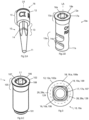
- Figs. 6 and 7 show an analog 50 in accordance with the present invention.
- the analog extends along a longitudinal axis L from apical end 51 to coronal end 52 and has an anti-rotation section 53 on its external surface.
- this anti-rotation section is formed by four planar, axially extending surfaces 54 evenly spaced about the longitudinal axis L and running parallel to this. These surfaces 54 create a non-circular symmetric cross-section in a plane perpendicular to the longitudinal axis L and enable the analog 50 to be rotationally fixed directly or indirectly within a dental model.
- An analog head 55 is provided at the coronal end 52 of the analog 50, coronal of the anti-rotation section 53.
- the analog head 55 comprises a blind bore 56 extending along longitudinal axis L.
- Blind bore 56 comprises anti-rotation means 57 in the form of a section of the bore having a non-circular symmetric cross-section in a plane perpendicular to the longitudinal axis L.
- the cross-section of the anti-rotation means 57 takes the form of a square with rounded edges.
- the blind bore 56 further comprises a threaded section 59.
- the coronal end of the blind bore 56 is surrounded by an abutment contact surface 58, which in the present embodiment is a planar surface extending perpendicular to the longitudinal axis L.
- an abutment contact surface 58 Directly adjacent to the radially outer edge of the abutment contact surface 58 and extending to the radially outermost edge of the analog head 55 is a discontinuous prosthesis contact surface 60.
- the prosthesis contact surface 60 of the analog of the present invention is formed by the coronal end of a plurality of circumferentially spaced struts 61. This leads to gaps being created between the struts 61.
- each strut 61 extends the full radial length of the prosthesis contact surface 60.
- Four struts 61 are provided at evenly spaced intervals about the longitudinal axis L.
- the struts 61 are angularly aligned with the anti-rotation means 57, although in other embodiments more, e.g. eight, or less evenly spaced struts could be provided.
- the struts 61 extend axially and radially from sidewall 63.
- the coronal most part of the struts 61 are triangular in their transverse cross-section.
- the struts 61 are roof shaped, such that each side of each struts 61 tapers evenly inwards towards one another in the coronal direction to form a central ridge 62.
- the ridges 62 are as narrow as possible to prevent, or at least limit, cement build up on these ridges 62.
- the ridges 62 form the prosthesis contact surface 60.
- the sidewall 63 of the analog head 55 between the struts 61 curves radially outwards in the apical direction in order to direct any cement overspill away from the coronal end of the analog 50.
- Analog 50 is designed for use with implant 1.
- the abutment connection geometry of the analog 50 including the blind bore 56, matches the abutment connection geometry of the implant 1.
- the abutment contact surface 58 matches the abutment contact surface 128, such that abutment contact surface 58 forms a planar surface perpendicular to the longitudinal axis L at the same radial location relative to the longitudinal axis L as abutment contact surface 128 relative to axis L1.
- the abutment contact surface 58 extends about the full circumference of the analog 50.
- Prosthesis contact surface 60 also matches prosthesis contact surface 129 of implant 1, such that prosthesis contact surface 60 has the same longitudinal cross-section, in this embodiment planar and perpendicular to the longitudinal axis L, as prosthesis contact surface 129 and in addition has the same axial and radial location relative to the longitudinal axis L and abutment contact surface 58 as portions of the prosthesis contact surface 129 relative to the longitudinal axis L1 and abutment contact surface 128.
- prosthesis contact surface 60 of analog 50 only matches the prosthesis contact surface 129 of the implant 1 at circumferentially spaced locations, such that the prosthesis contact surface 60 is discontinuous in comparison to the prosthesis contact surface 129 of the implant.
- both the abutment contact surface 128 and prosthesis contact surface 129 of the implant 1, and hence the abutment contact surface 58 and prosthesis contact surface 60 of the analog 50, are planar and perpendicular to the their respective longitudinal axes L1, L.
- the abutment contact surface 58 and prosthesis contact surface 60 of the analog 50 can be designed to match any shape of abutment contact surface 128 and prosthesis contact surface 129 of the implant 1.
- Fig. 8 shows, in longitudinal cross-section along line A-A of Fig. 7 , the abutment 20 of Fig. 4 in combination with analog 50.
- the differing radial extents of the abutment contact surface 58 and prosthesis contact surface 60 can be clearly seen. It can further be seen that the apically facing contact surface 24 of the abutment 20 fully contacts the abutment contact surface 58 of the analog 50 while the prosthesis contact surface 60 remains exposed beyond this.
- abutment 20 can be seated on analog 50 in an identical manner to how it is seated on implant 1, as the abutment connection geometry of the analog 50, including abutment contact surface 58, matches the abutment connection geometry of the implant 1, including abutment contact surface 128.
- the abutment shoulder 21 completely covers abutment contact surface 58 around the full circumference of the analog 50, thus sealing the blind bore 56 and preventing any cement from passing into this bore.
- Circumferentially spaced struts 61 extend radially beyond abutment 20 creating the discontinuous prosthesis contact surface 60.
- a prosthesis having a suitable cavity for accommodating the coronal portion of abutment 20 can thus be placed over abutment 20 until it rests on the prosthesis contact surface 60. As this surface 60 matches prosthesis contact surface 129 of the implant 1, it will correctly position the prosthesis, relative to the abutment 20, and support this during bonding to the abutment.
- the analog 50 is designed such that this can be placed either directly or indirectly in to a dental model.
- the anti-rotation section 53 and parts of the analog 50 apical of this have a uniform or apically decreasing radius, such that no undercuts are formed. This enables the analog 50 to be removeably placed in the model, although in alternative embodiments analog 50 could comprise a similar anti-rotation means 13a to analog 10a of Fig. 2B for permanent fixture within the model.
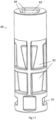
- a sleeve 80 which can be used with the analog 50 is shown in Figs. 11 and 12 .
- the exterior of the sleeve comprises a plurality of grooves 81 and indents 82, which form undercuts that fix the sleeve 80 within hardened modelling material.
- the sleeve comprises a blind bore 83 which is complementary in shape to the external shape of the anti-rotation section 53 and apical portion of the analog 50.
- the blind bore 83 of the sleeve 80 comprises four planar surfaces 84 which correspond to the planar surfaces 54 of the analog 50, thus enabling this to be non-rotationally fixed within the sleeve.
- the analog 50 can be inserted and removed from the sleeve 80 as often as is necessary.
Claims (17)
- Zahnimplantatsystem umfassend ein Zahnimplantat (1) und ein zugehöriges Implantatanalog (50),wobei sich das Implantat entlang einer Längsachse (L1) von einem apikalen Ende (101) zu einem koronalen Ende (102) erstreckt und umfassteine Außenfläche zum Verankern und zur Osseointegration in Knochen,einen koronalen Endabschnitt (105) mit einer Abutmentverbindungsgeometrie, geeignet zum Zusammenwirken mit einem Abutment, so dass das Abutment in einer oder mehreren definierten Positionen auf das Implantat gesetzt werden kann, wobei die Abutmentverbindungsgeometrie umfassteine koronal gewandte Abutmentkontaktfläche (128), die sich um den vollen Umfang des Implantats erstreckt und zum direkten Kontakt mit einem Abutment und zum Bereitstellen eines Anschlags, der die axiale Position des Abutments relativ zu dem Implantat definiert, geeignet ist, wobei der koronale Endabschnitt ferner umfassteine koronal gewandte Prothesenkontaktfläche (129), geeignet zum Kontakt mit einer Prothese, wobei die Fläche radial über die Abutmentkontaktfläche hinaus geht, wobei die Prothesenkontaktfläche eine durchgehende Fläche ist, die sich um den vollen Umfang des Implantats erstreckt,wobei sich das zugehörige Analog (50) entlang einer Längsachse (L) von einem apikalen Ende (51) zu einem koronalen Ende (52) erstreckt und umfassteine Außenfläche, die einen Antirotationsabschnitt (53) umfasst, der zu der drehfesten Fixierung in einem Zahnmodell einen nicht kreissymmetrischen Querschnitt in einer Ebene senkrecht zu der Längsachse aufweist,einen Analogkopf (55), der sich an dem koronalen Ende des Analogs befindet, wobei der Kopf umfassteine Abutmentverbindungsgeometrie, geeignet zum Zusammenwirken mit einem Abutment, so dass das Abutment in den gleichen einen oder mehreren definierten Positionen wie auf das Implantat auf das Analog gesetzt werden kann, wobei die Abutmentverbindungsgeometrie umfassteine koronal gewandte Abutmentkontaktfläche (58), geeignet zum direkten Kontakt des Abutments und zu der Bereitstellung eines Anschlags, der die axiale Position des Abutments relativ zu dem Analog definiert, wobei der Kopf ferner umfassteine koronal gewandte Prothesenkontaktfläche (60), geeignet zum Kontakt mit einer Prothese, wobei die Fläche radial über die Abutmentkontaktfläche hinaus geht,wobei die Abutmentkontaktfläche des Analogs den gleichen Längsquerschnitt und die gleiche radiale Position relativ zu ihrer Längsachse wie wenigstens ein Teil der Abutmentkontaktfläche des Implantats um den gesamten Umfang des Analogs aufweist, so dass die Abutmentkontaktfläche des Analogs wenigstens mit einem Teil der Abutmentkontaktfläche des Implantats um seinen gesamten Umfang zusammenpasst, undwobei die Prothesenkontaktfläche des Analogs den gleichen Längsquerschnitt und die gleiche Position relativ zu seiner Abutmentkontaktfläche und Längsachse wie wenigstens ein oder mehrere Teile der Prothesenkontaktfläche des Implantats aufweist, so dass die Prothesenkontaktfläche des Analogs mit einem oder mehreren Teilen der Prothesenkontaktfläche des Implantats zusammenpasst,wobei die Prothesenkontaktfläche des Analogs an diskreten Positionen um den Umfang des Analogs und/oder an wenigstens einer radialen Position entfernt von der Abutmentkontaktfläche des Analogs angeordnet ist, so dass im Vergleich zu der Prothesenkontaktfläche des Implantats die Prothesenkontaktfläche des Analogs in wenigstens der Umfangs- und/oder der Radialrichtung unterbrochen ist.
- Zahnimplantatsystem gemäß Anspruch 1, ferner umfassend ein Abutment (20) mit einem apikalen Abschnitt (20a) und einem koronalen Abschnitt (20b), wobei sich wenigstens der apikale Abschnitt entlang einer Längsachse (LB) erstreckt, wobei der apikale Abschnitt umfassteine Verbindungsgeometrie (22) zum Zusammenwirken mit der Abutmentverbindungsgeometrie des Implantats (1) und des Analogs (50), so dass das Abutment in die gleiche eine oder mehreren definierten Positionen sowohl an dem Implantat als auch an dem Abutment gesetzt werden kann, wobei die Verbindungsgeometrie umfassteine apikal gewandte Kontaktfläche (24), die zu den Abutmentkontaktflächen (128, 58) des Implantats und Analogs komplementär ist, zum direkten Kontakt mit den Abutmentkontaktflächen, um die axiale Position des Abutments relativ zu dem Implantat und dem Analog zu definieren, wobei die apikal gewandte Kontaktfläche in der Umfangsrichtung durchgehend ist,wobei, wenn das Abutment auf das Implantat gesetzt ist, die apikal gewandte Kontaktfläche des Abutments mit der Abutmentkontaktfläche des Implantats um den gesamten Umfang des Implantats Kontakt bildet, wobei das Abutment radial einwärts der Prothesenkontaktfläche (129) angeordnet ist, so dass diese Fläche freiliegend bleibt,und, wenn das Abutment auf das Analog gesetzt ist, die apikal gewandte Kontaktfläche des Abutments Kontakt mit der Abutmentkontaktfläche des Analogs um den gesamten Umfang des Analogs bildet, wobei das Abutment radial einwärts der Prothesenkontaktfläche (60) des Analogs angeordnet ist, so dass diese Fläche freiliegend bleibt, wobei das Abutment die gleiche Position relativ zu der Prothesenkontaktfläche des Analogs aufweist, wie es relativ zu der Prothesenkontaktfläche des Implantats aufweist, wenn auf dem Implantat aufgesetzt.
- Zahnimplantatsystem gemäß Anspruch 1 oder 2, wobei die Abutmentkontaktfläche (128) des Implantats (1) und die Abutmentkontaktfläche (58) des Analogs (50) in allen ihren Längsquerschnitten linear sind.
- Zahnimplantatsystem gemäß Anspruch 1, 2 oder 3, wobei die Abutmentkontaktfläche (128) des Implantats (1) und die Abutmentkontaktfläche (58) des Analogs (50) um die Längsachse des Implantats bzw. des Analogs kreissymmetrisch sind.
- Zahnimplantatsystem gemäß einem der vorstehenden Ansprüche, wobei die Prothesenkontaktfläche (129) des Implantats (1) und die Prothesenkontaktfläche (60) des Analogs (50) in ihrem Längsquerschnitt linear sind.
- Zahnimplantatsystem gemäß einem der vorstehenden Ansprüche, wobei die Prothesenkontaktfläche (129) des Implantats (1) und die Prothesenkontaktfläche (60) des Analogs (50) um die Längsachse des Implantats bzw. des Analogs kreissymmetrisch sind.
- Zahnimplantatsystem gemäß einem der vorstehenden Ansprüche, wobei die Prothesenkontaktfläche (60) des Analogs (50) von dem koronalen Ende einer Vielzahl von in Umfangsrichtung beabstandeten Streben (61) oder von einer oder mehreren ringförmigen Streben, die radial von der Abutmentkontaktfläche (58) beabstandet sind, gebildet wird.
- Zahnimplantatsystem gemäß Anspruch 7, wobei der Analogkopf (55) eine Seitenwand (63) umfasst, die sich apikal von der radial äußeren Kante der Abutmentkontaktfläche (58) erstreckt, wobei sich die Vielzahl von in Umfangsrichtung beabstandeten Streben (61) oder die eine oder mehreren ringförmigen Streben radial und axial von der Seitenwand erstrecken.
- Zahnimplantatsystem gemäß Anspruch 7 oder 8, wobei die Prothesenkontaktfläche (60) des Analogs (50) von dem koronalen Ende einer Vielzahl von in Umfangsrichtung beabstandeten Streben (61) gebildet wird, so dass die Prothesenkontaktfläche wenigstens in der Umfangsrichtung unterbrochen ist.
- Zahnimplantatsystem gemäß Anspruch 9, wobei sich jede in Umfangsrichtung beabstandete Strebe (61) über die gesamte radiale Länge der Prothesenkontaktfläche (60) des Analogs (50) erstreckt und das gesamte koronale Ende jeder Strebe die Prothesenkontaktfläche bildet.
- Zahnimplantatsystem gemäß Anspruch 9 oder 10, wenn abhängig von Anspruch 2, wobei die Breite des koronalen Endes jeder in Umfangsrichtung beabstandeten Strebe (61) kleiner als die Breite des Bogens des Drehspiels zwischen dem Analog (20) und dem Abutment (50) ist.
- Zahnimplantatsystem gemäß Anspruch 9, 10 oder 11, wobei die radial äußere Kante der Abutmentkontaktfläche (58) des Analogs (50) direkt an die radial innere Kante der Prothesenkontaktfläche (60) angrenzt, so dass diese Flächen miteinander Kontakt bilden.
- Zahnimplantatsystem gemäß einem der vorstehenden Ansprüche, wobei sich die Prothesenkontaktfläche (60) des Analogs (50) bis zu der radial äußersten Kante des Analogkopfes (55) erstreckt.
- Zahnimplantatsystem gemäß einem der vorstehenden Ansprüche, wobei die Abutmentverbindungsgeometrie des Implantats (1) und die Abutmentverbindungsgeometrie des Analogs (50) eine Blindbohrung (106, 56) umfassen, die sich entlang der Längsachse (LI, L) von dem koronalen Ende (101, 51) des Implantats bzw. des Analogs erstreckt, wobei die Blindbohrungen jeweils einen Gewindeabschnitt (109, 59) umfassen.
- Zahnimplantatsystem gemäß einem der vorstehenden Ansprüche, wobei die Abutmentverbindungsgeometrie des Implantats (1) ferner ein Antirotationsmittel (107) mit einem nicht kreissymmetrischen Querschnitt in einer Ebene senkrecht zu der Längsachse () des Implantats umfasst und die Abutmentverbindungsgeometrie des Analogs (50) ferner ein Antirotationsmittel (57) mit einem nicht kreissymmetrischen Querschnitt in einer Ebene senkrecht zu der Längsachse des Analogs (L) umfasst, wobei das Antirotationsmittel des Analogs einen identischen Querschnitt wie das Antirotationsmittel des Implantats aufweist.
- Zahnimplantatsystem gemäß einem der vorstehenden Ansprüche, wobei sich die Abutmentkontaktfläche (128) und die Prothesenkontaktfläche (129) des Implantats (1) und die Abutmentkontaktfläche (58) und die Prothesenkontaktfläche (60) des Analogs (50) in der gleichen Ebene erstrecken.
- Zahnimplantatsystem gemäß einem der vorstehenden Ansprüche wenn abhängig von Anspruch 2, ferner umfassend eine Zahnprothese (70), die eine Abutmentverbindungsgeometrie umfasst, die zum Fixieren der Prothese an dem koronalen Abschnitt (20b) des Abutments (20) in einer oder mehreren definierten Positionen geeignet ist, wobei die Prothese ferner eine apikal gewandte Implantatkontaktfläche umfasst, wobei die Fläche komplementär zu der Prothesenkontaktfläche (129) des Implantats (1) und der Prothesenkontaktfläche (60) des Analogs (50) ist, so dass,wenn die Prothese über die Abutmentverbindungsgeometrie mit dem Abutment verbunden und das Abutment auf das Implantat gesetzt ist, die Implantatkontaktfläche der Prothese mit der Prothesenkontaktfläche um den gesamten Umfang des Implantats Kontakt bildet undwenn die Prothese über die Abutmentverbindungsgeometrie mit dem Abutment verbunden und das Abutment auf das Analog gesetzt ist, die Implantatkontaktfläche der Prothese mit der gesamten Fläche der unterbrochenen Prothesenkontaktfläche des Analogs Kontakt bildet.
Applications Claiming Priority (3)
| Application Number | Priority Date | Filing Date | Title |
|---|---|---|---|
| EP17161931 | 2017-03-20 | ||
| EP18711944.1A EP3600135B1 (de) | 2017-03-20 | 2018-03-19 | Implantatanalog |
| PCT/EP2018/056860 WO2018172270A1 (en) | 2017-03-20 | 2018-03-19 | Implant analog |
Related Parent Applications (2)
| Application Number | Title | Priority Date | Filing Date |
|---|---|---|---|
| EP18711944.1A Division EP3600135B1 (de) | 2017-03-20 | 2018-03-19 | Implantatanalog |
| EP18711944.1A Division-Into EP3600135B1 (de) | 2017-03-20 | 2018-03-19 | Implantatanalog |
Publications (2)
| Publication Number | Publication Date |
|---|---|
| EP3868329A1 EP3868329A1 (de) | 2021-08-25 |
| EP3868329B1 true EP3868329B1 (de) | 2023-12-13 |
Family
ID=58387775
Family Applications (2)
| Application Number | Title | Priority Date | Filing Date |
|---|---|---|---|
| EP18711944.1A Active EP3600135B1 (de) | 2017-03-20 | 2018-03-19 | Implantatanalog |
| EP21161587.7A Active EP3868329B1 (de) | 2017-03-20 | 2018-03-19 | Implantatanalog |
Family Applications Before (1)
| Application Number | Title | Priority Date | Filing Date |
|---|---|---|---|
| EP18711944.1A Active EP3600135B1 (de) | 2017-03-20 | 2018-03-19 | Implantatanalog |
Country Status (8)
| Country | Link |
|---|---|
| US (1) | US11331171B2 (de) |
| EP (2) | EP3600135B1 (de) |
| JP (1) | JP7093786B2 (de) |
| KR (1) | KR102559137B1 (de) |
| CN (1) | CN110430837B (de) |
| BR (1) | BR112019017287B1 (de) |
| ES (1) | ES2884974T3 (de) |
| WO (1) | WO2018172270A1 (de) |
Families Citing this family (3)
| Publication number | Priority date | Publication date | Assignee | Title |
|---|---|---|---|---|
| KR102353975B1 (ko) * | 2019-12-27 | 2022-01-24 | 오스템임플란트 주식회사 | 치과 임플란트용 어버트먼트 |
| KR102366157B1 (ko) * | 2020-03-17 | 2022-02-22 | 오스템임플란트 주식회사 | 임플란트 용 랩 아날로그, 그것과 결합되는 디지털 입체 모형의 제작 방법 |
| US20220183800A1 (en) * | 2020-12-10 | 2022-06-16 | Milan Madhavji | Scan bodies for digital impressions and systems, indicia, and methods of using scan bodies |
Family Cites Families (22)
| Publication number | Priority date | Publication date | Assignee | Title |
|---|---|---|---|---|
| US5934906A (en) | 1975-09-19 | 1999-08-10 | Shopvest, Inc. | Working model for prosthodontic preparation of a tooth for installation of an implant fixture |
| US4955811A (en) * | 1988-06-23 | 1990-09-11 | Implant Innovations, Inc. | Non-rotational single-tooth prosthodontic restoration |
| DE69637019T2 (de) | 1995-05-25 | 2007-08-16 | Implant Innovations, Inc., Palm Beach Gardens | Verdrehsicheres verbindungselement |
| TW332774B (en) | 1996-02-08 | 1998-06-01 | Straumann Inst Ag | Impression system for an implant end protruding from the human tissue structure |
| US6540516B1 (en) * | 1997-05-05 | 2003-04-01 | Atlantis Components, Inc. | Impression coping platform and related methods |
| US5829981A (en) | 1997-05-05 | 1998-11-03 | Atlantis Components, Inc. | One-piece impression coping for customized implant restorative systems |
| US6540514B1 (en) * | 1998-02-26 | 2003-04-01 | Theodore S. Falk | Method for isolating a dental implant |
| WO2006019225A1 (en) * | 2004-08-20 | 2006-02-23 | Dal Ho Lee | Dental implant, impression coping and lab analog for the dental implant |
| JP2008529572A (ja) * | 2005-02-08 | 2008-08-07 | バイオテクノロジー インスティチュート、アイ エムエーエス ディー、 エス.エル. | 細い歯科用インプラント及び関連する部品 |
| DE102005008273A1 (de) * | 2005-02-22 | 2006-08-24 | Mundorf, Sönke, Dr. | Ein- oder zweiteiliges Zahnimplantatsystem |
| US20090081613A1 (en) * | 2005-03-24 | 2009-03-26 | Biomed Est. | Implant analog |
| EP1967158A1 (de) * | 2007-03-06 | 2008-09-10 | Astra Tech AB | Dentales Implantat, Stützstruktur und Verfahren zur Implantierung eines dentalen Implantats |
| DE102010021601A1 (de) | 2010-05-26 | 2011-12-01 | Straumann Holding Ag | Analogimplantat |
| JP5156113B2 (ja) * | 2011-08-02 | 2013-03-06 | 株式会社松風 | 歯科用インプラント |
| KR20140067053A (ko) * | 2011-08-21 | 2014-06-03 | 레브 베데라크 | 치과용 임플란트 - 주문형 교각치 및 임플란트 상사형의 리플리카 |
| ES2383415B9 (es) | 2012-02-20 | 2013-10-30 | Phibo Dental Solutions, S.L. | Pilar dental para el soporte de prótesis dentales y método de fabricación del mismo |
| KR101597151B1 (ko) * | 2012-08-24 | 2016-02-24 | 주식회사 티스트롱 | 치과용 임플란트 |
| DE102013104352A1 (de) | 2013-03-12 | 2014-09-18 | Nt-Trading Gmbh & Co. Kg | Implantat-Analog |
| GB2518849A (en) * | 2013-10-01 | 2015-04-08 | Nobel Biocare Services Ag | Dental Kit-of-parts and Method of assembling the same |
| GB2519296A (en) * | 2013-10-15 | 2015-04-22 | Nobel Biocare Services Ag | Dental implant replica |
| JP2017029261A (ja) | 2015-07-29 | 2017-02-09 | 恭久 高橋 | フィクスチャー |
| EP3120803A1 (de) * | 2015-07-24 | 2017-01-25 | Nobel Biocare Services AG | Halteelement zur anbringung einer ersten zahnkomponente an einer zweiten zahnkomponente und zahnbaugruppe mit dem halteelement |
-
2018
- 2018-03-19 ES ES18711944T patent/ES2884974T3/es active Active
- 2018-03-19 CN CN201880019625.9A patent/CN110430837B/zh active Active
- 2018-03-19 BR BR112019017287-4A patent/BR112019017287B1/pt active IP Right Grant
- 2018-03-19 WO PCT/EP2018/056860 patent/WO2018172270A1/en unknown
- 2018-03-19 KR KR1020197027693A patent/KR102559137B1/ko active IP Right Grant
- 2018-03-19 US US16/494,371 patent/US11331171B2/en active Active
- 2018-03-19 EP EP18711944.1A patent/EP3600135B1/de active Active
- 2018-03-19 EP EP21161587.7A patent/EP3868329B1/de active Active
- 2018-03-19 JP JP2019551310A patent/JP7093786B2/ja active Active
Also Published As
| Publication number | Publication date |
|---|---|
| EP3868329A1 (de) | 2021-08-25 |
| ES2884974T3 (es) | 2021-12-13 |
| KR102559137B1 (ko) | 2023-07-24 |
| CN110430837A (zh) | 2019-11-08 |
| KR20190122730A (ko) | 2019-10-30 |
| BR112019017287A2 (pt) | 2020-04-14 |
| JP7093786B2 (ja) | 2022-06-30 |
| BR112019017287B1 (pt) | 2022-12-27 |
| JP2020511234A (ja) | 2020-04-16 |
| WO2018172270A1 (en) | 2018-09-27 |
| EP3600135B1 (de) | 2021-05-05 |
| US20200085543A1 (en) | 2020-03-19 |
| CN110430837B (zh) | 2021-08-03 |
| EP3600135A1 (de) | 2020-02-05 |
| US11331171B2 (en) | 2022-05-17 |
Similar Documents
| Publication | Publication Date | Title |
|---|---|---|
| JP7099954B2 (ja) | 走査可能な特徴を備えたヒーリングキャップ | |
| EP2025302B1 (de) | Ein Zahnsystem für ein Verfahren zum Formen einer Zahnprothese | |
| KR102302292B1 (ko) | 맞춤형 치과용 임플란트 어버트먼트 및 임프레션 포스트 용 몰드 | |
| EP2869782B1 (de) | Abutment-system | |
| US6672871B2 (en) | Coping with standoffs | |
| KR100677870B1 (ko) | 치유 지대주 및 그를 구비한 치과용 임플란트 | |
| EP2601906B1 (de) | Abutment-Inlay | |
| US6149433A (en) | One-piece impression coping for customized implant restorative systems | |
| US20120171638A1 (en) | Holding piece for an implant | |
| JP2012517861A (ja) | インプラントと共に使用される構成要素、および関連する方法 | |
| EP3868329B1 (de) | Implantatanalog | |
| EP2498717A2 (de) | Zahnimplantatsystem und verfahren zu seiner verwendung | |
| KR100842318B1 (ko) | 치과 임플란트용 슬리브 및 그를 구비한 치과 임플란트 | |
| AU2018204181B2 (en) | Combination impression coping and scan body | |
| EP3886757B1 (de) | Zweiteilige modellierungshilfe | |
| EP2459106B1 (de) | Stütze für ein zahnimplantat | |
| JP2021526400A (ja) | 歯肉中部インプラントシステム | |
| JP2013520253A (ja) | アタッチメント部材及び歯科修復物 | |
| CN105101906B (zh) | 具有带一个或多个外圈的安装元件的单件式或多件式种植系统 | |
| RU2758761C1 (ru) | Способ изготовления цельнокерамической коронки с винтовой фиксацией на импланте | |
| KR200428093Y1 (ko) | 치유 지대주 및 그를 구비한 치과용 임플란트 | |
| KR102500193B1 (ko) | 보철물이 적절하게 나사조임되거나 클립 유지되는 것을 허용하는 치과 임플란트 상의 보철물을 위한 듀얼 고정 시스템 |
Legal Events
| Date | Code | Title | Description |
|---|---|---|---|
| PUAI | Public reference made under article 153(3) epc to a published international application that has entered the european phase |
Free format text: ORIGINAL CODE: 0009012 |
|
| STAA | Information on the status of an ep patent application or granted ep patent |
Free format text: STATUS: THE APPLICATION HAS BEEN PUBLISHED |
|
| AC | Divisional application: reference to earlier application |
Ref document number: 3600135 Country of ref document: EP Kind code of ref document: P |
|
| AK | Designated contracting states |
Kind code of ref document: A1 Designated state(s): AL AT BE BG CH CY CZ DE DK EE ES FI FR GB GR HR HU IE IS IT LI LT LU LV MC MK MT NL NO PL PT RO RS SE SI SK SM TR |
|
| STAA | Information on the status of an ep patent application or granted ep patent |
Free format text: STATUS: REQUEST FOR EXAMINATION WAS MADE |
|
| 17P | Request for examination filed |
Effective date: 20220224 |
|
| RBV | Designated contracting states (corrected) |
Designated state(s): AL AT BE BG CH CY CZ DE DK EE ES FI FR GB GR HR HU IE IS IT LI LT LU LV MC MK MT NL NO PL PT RO RS SE SI SK SM TR |
|
| STAA | Information on the status of an ep patent application or granted ep patent |
Free format text: STATUS: EXAMINATION IS IN PROGRESS |
|
| 17Q | First examination report despatched |
Effective date: 20221103 |
|
| GRAP | Despatch of communication of intention to grant a patent |
Free format text: ORIGINAL CODE: EPIDOSNIGR1 |
|
| STAA | Information on the status of an ep patent application or granted ep patent |
Free format text: STATUS: GRANT OF PATENT IS INTENDED |
|
| INTG | Intention to grant announced |
Effective date: 20230628 |
|
| GRAS | Grant fee paid |
Free format text: ORIGINAL CODE: EPIDOSNIGR3 |
|
| P01 | Opt-out of the competence of the unified patent court (upc) registered |
Effective date: 20230928 |
|
| GRAA | (expected) grant |
Free format text: ORIGINAL CODE: 0009210 |
|
| STAA | Information on the status of an ep patent application or granted ep patent |
Free format text: STATUS: THE PATENT HAS BEEN GRANTED |
|
| AC | Divisional application: reference to earlier application |
Ref document number: 3600135 Country of ref document: EP Kind code of ref document: P |
|
| AK | Designated contracting states |
Kind code of ref document: B1 Designated state(s): AL AT BE BG CH CY CZ DE DK EE ES FI FR GB GR HR HU IE IS IT LI LT LU LV MC MK MT NL NO PL PT RO RS SE SI SK SM TR |
|
| REG | Reference to a national code |
Ref country code: GB Ref legal event code: FG4D |
|
| REG | Reference to a national code |
Ref country code: CH Ref legal event code: EP |
|
| REG | Reference to a national code |
Ref country code: DE Ref legal event code: R096 Ref document number: 602018062795 Country of ref document: DE |
|
| REG | Reference to a national code |
Ref country code: IE Ref legal event code: FG4D |
|
| PG25 | Lapsed in a contracting state [announced via postgrant information from national office to epo] |
Ref country code: GR Free format text: LAPSE BECAUSE OF FAILURE TO SUBMIT A TRANSLATION OF THE DESCRIPTION OR TO PAY THE FEE WITHIN THE PRESCRIBED TIME-LIMIT Effective date: 20240314 |
|
| REG | Reference to a national code |
Ref country code: LT Ref legal event code: MG9D |
|
| PG25 | Lapsed in a contracting state [announced via postgrant information from national office to epo] |
Ref country code: LT Free format text: LAPSE BECAUSE OF FAILURE TO SUBMIT A TRANSLATION OF THE DESCRIPTION OR TO PAY THE FEE WITHIN THE PRESCRIBED TIME-LIMIT Effective date: 20231213 |
|
| REG | Reference to a national code |
Ref country code: NL Ref legal event code: MP Effective date: 20231213 |
|
| PG25 | Lapsed in a contracting state [announced via postgrant information from national office to epo] |
Ref country code: LT Free format text: LAPSE BECAUSE OF FAILURE TO SUBMIT A TRANSLATION OF THE DESCRIPTION OR TO PAY THE FEE WITHIN THE PRESCRIBED TIME-LIMIT Effective date: 20231213 Ref country code: GR Free format text: LAPSE BECAUSE OF FAILURE TO SUBMIT A TRANSLATION OF THE DESCRIPTION OR TO PAY THE FEE WITHIN THE PRESCRIBED TIME-LIMIT Effective date: 20240314 Ref country code: BG Free format text: LAPSE BECAUSE OF FAILURE TO SUBMIT A TRANSLATION OF THE DESCRIPTION OR TO PAY THE FEE WITHIN THE PRESCRIBED TIME-LIMIT Effective date: 20240313 |
|
| PGFP | Annual fee paid to national office [announced via postgrant information from national office to epo] |
Ref country code: DE Payment date: 20240320 Year of fee payment: 7 Ref country code: GB Payment date: 20240321 Year of fee payment: 7 |