EP3867472B1 - Kraftfahrzeug-schloss - Google Patents
Kraftfahrzeug-schloss Download PDFInfo
- Publication number
- EP3867472B1 EP3867472B1 EP19783418.7A EP19783418A EP3867472B1 EP 3867472 B1 EP3867472 B1 EP 3867472B1 EP 19783418 A EP19783418 A EP 19783418A EP 3867472 B1 EP3867472 B1 EP 3867472B1
- Authority
- EP
- European Patent Office
- Prior art keywords
- pawl
- arch
- locking mechanism
- latch
- motor vehicle
- Prior art date
- Legal status (The legal status is an assumption and is not a legal conclusion. Google has not performed a legal analysis and makes no representation as to the accuracy of the status listed.)
- Active
Links
Images
Classifications
-
- E—FIXED CONSTRUCTIONS
- E05—LOCKS; KEYS; WINDOW OR DOOR FITTINGS; SAFES
- E05B—LOCKS; ACCESSORIES THEREFOR; HANDCUFFS
- E05B77/00—Vehicle locks characterised by special functions or purposes
- E05B77/36—Noise prevention; Anti-rattling means
-
- E—FIXED CONSTRUCTIONS
- E05—LOCKS; KEYS; WINDOW OR DOOR FITTINGS; SAFES
- E05B—LOCKS; ACCESSORIES THEREFOR; HANDCUFFS
- E05B77/00—Vehicle locks characterised by special functions or purposes
- E05B77/36—Noise prevention; Anti-rattling means
- E05B77/38—Cushion elements, elastic guiding elements or holding elements, e.g. for cushioning or damping the impact of the bolt against the striker during closing of the wing
-
- E—FIXED CONSTRUCTIONS
- E05—LOCKS; KEYS; WINDOW OR DOOR FITTINGS; SAFES
- E05B—LOCKS; ACCESSORIES THEREFOR; HANDCUFFS
- E05B81/00—Power-actuated vehicle locks
- E05B81/12—Power-actuated vehicle locks characterised by the function or purpose of the powered actuators
- E05B81/14—Power-actuated vehicle locks characterised by the function or purpose of the powered actuators operating on bolt detents, e.g. for unlatching the bolt
-
- E—FIXED CONSTRUCTIONS
- E05—LOCKS; KEYS; WINDOW OR DOOR FITTINGS; SAFES
- E05B—LOCKS; ACCESSORIES THEREFOR; HANDCUFFS
- E05B85/00—Details of vehicle locks not provided for in groups E05B77/00 - E05B83/00
- E05B85/20—Bolts or detents
- E05B85/24—Bolts rotating about an axis
- E05B85/26—Cooperation between bolts and detents
Definitions
- the invention relates to a motor vehicle lock, in particular a motor vehicle door lock, with a locking mechanism consisting of a rotary latch and at least one pawl, wherein the pawl exerts an opening torque on the rotary latch, wherein the pawl further has an arcuate contact region with a locking contour of the rotary latch, and wherein the contact region of the pawl has a first arcuate section and a second arcuate section, each with different radii.
- motor vehicle locks are not limited to motor vehicle door locks. In principle, this can also refer to tailgate locks, front hood locks, tank flap locks, loading flap locks, etc. and are included in the invention.
- a two-pawl or multi-pawl locking mechanism is often used, as is the case with DE 10 2013 103 245 A1 the applicant.
- a comfort latch and a locking latch are implemented here. The comfort latch is blocked using the locking latch and in turn ensures that the rotary latch assumes and maintains its closed or latched position. This has basically proven to be successful.
- a flat contour area is provided on the pawl, which causes a locking in the pre-locking position.
- a different contour area is provided on the pawl for the main locking position. In this way, the pre-locking position can be provided on the same locking level as the main locking position.
- DE 20 2012 000134 U1 discloses another motor vehicle door lock with a locking mechanism consisting of a rotary latch and a pawl.
- the pawl has a locking contour with a holding contour and a rolling contour.
- the invention is based on the technical problem of further developing such a motor vehicle lock and in particular a motor vehicle door lock in such a way that the functionality is improved and in particular a safe engagement when closing as well as a perfect opening are ensured.
- the invention proposes a motor vehicle lock according to claim 1. 11
- the first arc section of the contact area of the pawl has a larger radius in the closing direction of the locking mechanism than the following second arc section with the same radius.
- This design rule ensures that the first arc section with the larger radius in the closing direction of the locking mechanism has a large so-called "pre-cut".
- the pre-cut presses the load on the first arc section with the larger radius in accordance with the explanations in the previously mentioned and referred to DE 10 2013 103 245 how large the opening torque of the latch is designed for the rotary latch. Since the first arc section of the contact area of the latch with the catch contour of the rotary latch has a larger radius than the following second arc section, this also corresponds to a force from the latch to the rotary latch at a higher torque is exerted during an opening process than in the second arc section. In this way, any dirt or holding forces present in the contact area between the latch and the catch contour of the rotary latch can be easily overcome. On the other hand, these increased torques may be associated with increased forces when opening the locking mechanism, as will be explained in more detail below.
- the two curved sections in the contact area of the latch are arranged and designed in such a way that they directly adjoin one another in the closing direction of the locking mechanism.
- the two curved sections adjoining one another ensure that the pre-cut, i.e. the opening torque or the locking force exerted by the latch on the rotary latch, is maintained.
- the opening torque is designed to be variable, in such a way that the opening torque decreases in the closing direction of the locking mechanism.
- the two arch sections are also equipped with different arch lengths.
- the first arch section usually has a longer arch length than the second arch section.
- Arch lengths of 8 mm and more for the first arch section have proven to be particularly advantageous.
- the second arch section is equipped with an arch length of 5 mm and less.
- the design is such that the first curved section in the contact area of the pawl in the closing direction of the locking mechanism is adapted to the locking contour of the rotary latch.
- the design is such that the first curved section of the pawl in question overlaps with an associated curved contour area of the locking contour of the rotary latch over a certain arc length. This overlap makes the area of the first curved section of the contact area of the pawl less sensitive to dust, dirt or any holding forces.
- the pawl of the motor vehicle lock according to the invention is generally a comfort pawl which, together with an additional pawl and the rotary latch, defines a two-pawl locking mechanism or a multi-pawl locking mechanism.
- the design is usually such that the second curved section of the comfort pawl is adapted to an arcuate contact area of the pawl for the comfort pawl.
- the comfort latch is usually equipped with a spring which acts on the comfort latch in an opening direction and also ensures that the rotary latch is subjected to the opening torque or opening moment described above via the first curved section and the second curved section.
- the invention ensures overall that, when the locking mechanism is in the closed position, the opening torque exerted by the comfort latch on the rotary latch approximately corresponds to the closing torque that the pawl securing the comfort latch exerts on the comfort latch via its arc-shaped contact area. This means that the comfort latch is held securely in its contact with the locking contour of the rotary latch. At the same time, the pawl can easily be pivoted away from the comfort latch during an opening process, which then releases the rotary latch.
- the radii of the arc-shaped contact area of the pawl on the one hand and the second arc section of the comfort latch on the other hand largely overlap.
- the radius of the second arc section of the comfort latch can essentially correspond to the radius of the contact area of the pawl.
- the pawl can be lifted out with relatively little force and releases the comfort pawl when the locking mechanism is opened.
- the comfort pawl swings open with the help of the force of the spring and supports the opening movement of the rotary latch with the opening torque increasing in the opening direction of the locking mechanism.
- the variable design of the pre-cut ensures that the opening torque exerted by the comfort pawl on the pawl is reduced in the closing direction of the locking mechanism, so that it can be safely engaged.
- the comfort latch is made available in the rotary latch when the locking mechanism is closed. In this way, the overall functionality is significantly improved compared to the state of the art. This is where the main advantages can be seen.
- the figures show a motor vehicle lock, which in the exemplary embodiment is a motor vehicle door lock and in particular a motor vehicle side door lock.
- This has a locking mechanism 1, 2, 3, which is made up of a rotary latch 1 and two pawls 2, 3.
- the first pawl 2 is designed as a comfort pawl
- the further second pawl 3 is or can be designed as a second pawl or blocking pawl that secures the comfort pawl 2 in the closed position.
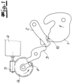
- the Fig. 1 shows the closed position of the locking mechanism or 2-pawl locking mechanism 1, 2, 3. In the closed position, the blocking pawl 3 ensures that the comfort pawl 2 secures the rotary latch 1 and does not swing away.
- the electric motor drive 4-7 functions as an opening drive for electrically opening the locking mechanism 1, 2, 3.
- the electric motor drive 4-7 consists of an electric motor 4, a worm 5 arranged on an output shaft of the electric motor 4 and a worm wheel 6 meshing with the worm 5.
- the worm wheel 6 is rotated as shown in the Fig. 1 in the counterclockwise direction indicated here.
- a radial projection 7 arranged on the worm gear 6 can act on the blocking pawl 3 in such a way that it is lifted from its engagement with the comfort pawl 2.
- the comfort pawl 2 can swing open due to the force of a spring (not shown) and in turn releases the rotary latch 1, which also swings open supported by a spring, as shown by another arrow in the Fig. 1 suggests.
- the comfort latch 2 is equipped with an arc-shaped contact area 8, 9.
- the contact area 8, 9 on the comfort latch 2 interacts with a locking contour 10 on the rotary latch 1.
- the contact area 8, 9 of the comfort latch 2 is equipped with a first curved section 8 and a second curved section 9 in the closing direction of the locking mechanism 1, 2, 3, which each have different radii R 1 , R 2 .
- the first arc section 8 which first interacts with the locking contour 10 of the rotary latch 1 in the closing direction S of the locking mechanism 1, 2, 3, has a larger radius or first radius R 1 than the then following second arc section 9, the associated further radius R 2 of which is smaller in comparison.
- the two curved sections 8, 9, i.e. the first curved section 8 and the second curved section 9 on the comfort latch 2 in the closing direction S of the locking mechanism 1, 2, 3, are directly connected to one another, i.e. without a gap or an intermediate area.
- the two curved sections 8, 9 are equipped with different curved lengths L 1 and L 2.
- the curved length L 1 of the first curved section 8 is generally greater than or equal to 8 mm.
- the second curved section 9 is equipped with a curved length L 2 which is 5 mm or less in the exemplary embodiment.
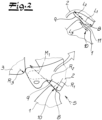
- the first arc section 8 is adapted to the locking contour 10 of the rotary latch 1, as can be seen in particular in the Fig. 2 recognizes.
- the design is such that the first arc section 8 of the comfort latch 2 overlaps with a corresponding arc-shaped contour area 11 of the rotary latch 1 over a certain arc length L 3.
- the overlap between the arc length L 3 of the arc-shaped contour area 11 of the locking contour 10 of the rotary latch 1 with the first arc section 8 on the comfort latch 2 may be approximately 20% to 70% of the arc length L 1 of the first arc section 8 on the comfort latch 2, which of course only applies as an example.
- the second arc section 9 on the comfort pawl 2 is, in contrast, adapted to an arc-shaped contact area 12 of the pawl 3.
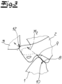
- the radius R 2 of the second arc section 9 on the comfort pawl 2 essentially corresponds to the associated radius R 3 of the contact area 12 of the pawl 3, which in the Fig. 3 shown closed position of the Locking mechanism 1, 2, 3 moves against the comfort latch 2 and ensures that the comfort latch 2 cannot swing open in the closed position shown there.
Landscapes
- Lock And Its Accessories (AREA)
Description
- Die Erfindung betrifft ein Kraftfahrzeug-Schloss, insbesondere Kraftfahrzeug-Türschloss, mit einem Gesperre aus einer Drehfalle und wenigstens einer Klinke, wobei die Klinke ein öffnendes Drehmoment auf die Drehfalle ausübt, wobei ferner die Klinke einen bogenförmigen Kontaktbereich mit einer Rastkontur der Drehfalle aufweist, und wobei der Kontaktbereich der Klinke einen ersten Bogenabschnitt und einen zweiten Bogenabschnitt mit jeweils unterschiedlichen Radien besitzt.
- Bei den vorgenannten Kraftfahrzeug-Schlössern handelt es sich nicht einschränkend um Kraftfahrzeug-Türschlösser. Grundsätzlich können an dieser Stelle auch Heckklappenschlösser, Fronthaubenschlösser, Tankklappenschlösser, Ladeklappenschlösser etc. gemeint sein und werden von der Erfindung mitumfasst.
- Bei solchen Kraftfahrzeug-Schlössern und insbesondere Kraftfahrzeug-Türschlössern wird im Stand der Technik nach der
WO 2013/163982 A2 so vorgegangen, dass die Drehfalle ein Drehmoment in die Klinke einleitet, und zwar insbesondere ein öffnendes Moment. Auf diese Weise wird der Öffnungsvorgang des zugehörigen Gesperres ausgehend von der Drehfalle und der Klinke bzw. Sperrklinke unterstützt. Das ist insbesondere dann hilfreich, wenn beispielsweise eine Heckklappe oder Fronthaube so weit geöffnet werden soll, dass ein Bediener einen Spalt hintergreifen kann, um die fragliche Haube oder Klappe zu öffnen. Vergleichbares gilt natürlich ebenso, wenn eine Kraftfahrzeug-Seitentür geöffnet werden soll. - Aus Gründen eines komfortablen Öffnens und insbesondere um ein geräuscharm arbeitendes Gesperre zu realisieren, wird oftmals mit einem Zweiklinken- oder Mehrklinkengesperre gearbeitet, wie es im Rahmen der
DE 10 2013 103 245 A1 der Anmelderin beschrieben wird. Hier sind eine Komfortklinke und eine Sperrklinke realisiert. Die Komfortklinke wird mithilfe der Sperrklinke blockiert und sorgt ihrerseits dafür, dass die Drehfalle ihre Schließstellung bzw. Raststellung einnimmt und beibehält. Das hat sich grundsätzlich bewährt. - Beim gattungsbildenden Stand der Technik nach der
DE 20 2009 019 025 U1 dient die dortige Sperrklinke nicht nur zum Verrasten der Drehfalle in der Vorrast und der Hauptrast. Vielmehr verfügt die Sperrklinke in der Vorrastposition über ein schließendes und auf die Drehfalle wirkendes Moment. Außerdem ist die Kontur bzw. der Kontaktbereich der Sperrklinke zusätzlich noch so beschaffen, dass in der Hauptrastposition die Sperrklinke ein öffnendes Moment auf die Drehfalle ausübt. - Im Detail ist dazu ein ebener Konturbereich an der Sperrklinke realisiert, welcher eine Verrastung in der Vorrast bewirkt. Demgegenüber ist ein hiervon abweichender Konturbereich an der Sperrklinke für die Hauptrast vorgesehen. Auf diese Weise soll insgesamt die Position Vorrast auf einer gleichen Gesperrebene wie die Position Hauptrast bereitgestellt werden können. - Ein vergleichbares Gesperre für ein Schloss eines Kraftfahrzeugs wird in der
DE 10 2009 029 031 A1 vorgestellt und beschrieben. -
DE 20 2012 000134 U1 offenbart einen weiteren Kraftfahrzeugtürverschluss mit einem Gesperre aus Drehfalle und Sperrklinke. Die Sperrklinke weist eine Verriegelungskontur mit einer Haltekontur und Abrollkontur auf. - Der genannte und zuvor gewürdigte Stand der Technik ist nicht frei von Mängeln. Denn sofern die Sperrklinke ein öffnendes Drehmoment auf die Drehfalle ausübt, wird dieses öffnende Moment beispielsweise erst während des Öffnens des Gesperres zur Verfügung gestellt. Als Folge hiervon sind in der Praxis Situationen möglich, die dazu führen, dass das öffnende Moment der Klinke eine verringerte oder gar keine Wirkung auf die Drehfalle hat. Dies gilt beispielsweise für den Fall, dass zwischen dem bogenförmigen Kontaktbereich an der Klinke und der Rastkontur der Drehfalle in Schließstellung des Gesperres Schmutz vorhanden ist oder sich beispielsweise in Folge einer langen Standzeit vergrößerte Haltekräfte bedingt durch Feuchtigkeit, Korrosion etc. einstellen. Als Folge hiervon lässt sich das zugehörige Kraftfahrzeug-Schloss unter Umständen nicht (mehr) einwandfrei öffnen, insbesondere elektrisch öffnen. Außerdem ist auch der Schließvorgang durch etwaigen Schmutz oder Staub in diesem Bereich beeinträchtigt. Hier will die Erfindung insgesamt Abhilfe schaffen.
- Der Erfindung liegt das technische Problem zugrunde, ein derartiges Kraftfahrzeug-Schloss und insbesondere Kraftfahrzeug-Türschloss so weiter zu entwickeln, dass die Funktionalität verbessert ist und insbesondere ein sicheres Einfallen beim Schließen ebenso wie ein einwandfreies Öffnen gewährleistet sind.
- Zur Lösung dieser technischen Problemstellung schlägt die Erfindung ein Kraffahrzeug-Schloss gemäß Anspruch 1 vor. 11
- Der erste Bogenabschnitt des Kontaktbereiches der Klinke weist in Schließrichtung des Gesperres einen größeren Radius als der folgende zweite Bogenabschnitt mit dem dortigen Radius auf.
- Durch diese Bemessungsregel wird zunächst einmal erreicht, dass der in Schließrichtung des Gesperres erste Bogenabschnitt mit dem größeren Radius einen großen sogenannten "Vorschnitt" aufweist. Tatsächlich drückt der Vorschnitt entsprechend den Erläuterungen in der zuvor bereits genannten und in Bezug genommenen
DE 10 2013 103 245 aus, wie groß das Öffnungsmoment der Klinke auf die Drehfalle ausgelegt ist. Da der erste Bogenabschnitt des Kontaktbereiches der Klinke mit der Rastkontur der Drehfalle über einen größeren Radius als der folgende zweite Bogenabschnitt verfügt, korrespondiert hierzu auch ein von der Klinke auf die Drehfalle bei einem Öffnungsvorgang ausgeübtes höheres Drehmoment als beim zweiten Bogenabschnitt. Auf diese Weise können im Kontaktbereich der Klinke mit der Rastkontur der Drehfalle vorhandene etwaige Verschmutzungen oder Haltekräfte einerseits problemlos überwunden werden. Andererseits sind mit diesen erhöhten Drehmomenten unter Umständen vergrößerte Kräfte beim Öffnen des Gesperres verbunden, wie dies nachfolgend noch im Detail erläutert wird. - Da der in Schließrichtung des Gesperres dem ersten Bogenabschnitt folgende zweite Bogenabschnitt mit dem demgegenüber geringeren Radius ausgerüstet ist, wird insbesondere in Schließstellung des Gesperres ein verringertes Drehmoment bzw. Öffnungsmoment der Klinke mit zunehmender Schließstellung beobachtet. Das ist insofern vorteilhaft, als hierdurch sichergestellt ist, dass die Klinke sicher in die Rastkontur der Drehfalle beim Schließvorgang des Gesperres einfallen kann, ohne dass das nach wie vor vorhandene öffnende Drehmoment bzw. Öffnungsmoment der Klinke dies verhindert oder erschwert. Hierin sind die wesentlichen Vorteile zu sehen.
- Erfindungsgemäß sind die beiden Bogenabschnitte im Kontaktbereich der Klinke so angeordnet und ausgelegt, dass sie in Schließrichtung des Gesperres unmittelbar aneinander anschließen. Das heißt, in Schließrichtung des Gesperres trifft die Rastkontur der Drehfalle zunächst auf den ersten Bogenabschnitt mit dem größeren Radius und folglich höheren Öffnungsmoment der Klinke und dann auf den zweiten Bogenabschnitt mit dem demgegenüber kleineren Radius und geringeren Öffnungsmoment bis die Schließstellung des Gesperres erreicht ist. Dadurch kann die Klinke sicher in die Rastkontur der Drehfalle einfallen und ist damit ein sicheres Einfallen beim Schließen gewährleistet. Die beiden aneinander anschließenden Bogenabschnitte sorgen in diesem Zusammenhang dafür, dass der Vorschnitt, also das von der Klinke auf die Drehfalle ausgeübte öffnende Drehmoment bzw. Öffnungsmoment variabel ausgelegt ist, und zwar derart, dass in Schließrichtung des Gesperres das Öffnungsmoment abnimmt.
- Um dies im Detail zu realisieren, sind die beiden Bogenabschnitte darüber hinaus mit unterschiedlichen Bogenlängen ausgerüstet. Tatsächlich verfügt der erste Bogenabschnitt regelmäßig über eine größere Bogenlänge als der zweite Bogenabschnitt. Hier haben sich Bogenlängen für den ersten Bogenabschnitt von 8 mm und mehr als besonders günstig erwiesen. Demgegenüber ist der zweite Bogenabschnitt mit einer Bogenlänge von 5 mm und weniger ausgerüstet.
- Außerdem ist die Auslegung so getroffen, dass der in Schließrichtung des Gesperres erste Bogenabschnitt im Kontaktbereich der Sperrklinke an die Rastkontur der Drehfalle angepasst ist. Dazu ist die Auslegung so getroffen, dass der fragliche erste Bogenabschnitt der Klinke mit einem zugehörigen bogenförmigen Konturbereich der Rastkontur der Drehfalle über eine bestimmte Bogenlänge überdeckt. Durch diese Überdeckung wird insgesamt der Bereich des ersten Bogenabschnittes des Kontaktbereiches der Klinke unempfindlicher gegenüber Staub, Schmutz oder etwaigen Haltekräften.
- Bei der Klinke des erfindungsgemäßen Kraftfahrzeug-Schlosses handelt es sich im Allgemeinen um eine Komfortklinke, welche zusammen mit einer zusätzlich vorgesehenen Sperrklinke und der Drehfalle ein Zweiklinkengesperre bzw. Mehrklinkengesperre definiert. Das heißt, die beiden Bogenabschnitte und folglich der Kontaktbereich der Klinke sind jeweils an der Komfortklinke angeordnet. Außerdem ist die Auslegung meistens so getroffen, dass der zweite Bogenabschnitt der Komfortklinke an einen bogenförmigen Anlagebereich der Sperrklinke für die Komfortklinke angepasst ist.
- Das heißt, in Schließstellung des Gesperres sorgt die Sperrklinke mit ihrem bogenförmigen Anlagebereich dafür, dass die Komfortklinke ihrerseits sicher in Eingriff mit der Rastkontur der Drehfalle gehalten wird und nicht in öffnendem Sinne aufschwenken kann. Tatsächlich ist die Komfortklinke meistens mit einer Feder ausgerüstet, welche die Komfortklinke in öffnendem Sinne beaufschlagt und auch dafür sorgt, dass über den ersten Bogenabschnitt und den zweiten Bogenabschnitt die Drehfalle mit dem zuvor bereits beschriebenen öffnenden Drehmoment bzw. Öffnungsmoment beaufschlagt wird.
- Durch die Anpassung des zweiten Bogenabschnittes der Komfortklinke an den bogenförmigen Anlagebereich der Sperrklinke für die Komfortklinke stellt die Erfindung insgesamt sicher, dass in Schließstellung des Gesperres das seitens der Komfortklinke auf die Drehfalle ausgeübte Öffnungsmoment in etwa dem Schließmoment entspricht, welches die die Komfortklinke sichernde Sperrklinke über ihren bogenförmigen Anlagebereich auf die Komfortklinke ausübt. Dadurch wird die Komfortklinke sicher in ihrer Anlage an der Rastkontur der Drehfalle gehalten. Zugleich kann die Sperrklinke bei einem Öffnungsvorgang unschwer von der Komfortklinke weggeschwenkt werden, welche daraufhin die Drehfalle freigibt. Das heißt, in Schließstellung des Gesperres kommt es größtenteils zu einer Überdeckung der Radien des bogenförmigen Anlagebereiches der Sperrklinke einerseits und des zweiten Bogenabschnittes der Komfortklinke andererseits. Beispielsweise kann der Radius des zweiten Bogenabschnittes der Komfortklinke im Wesentlichen dem Radius des Anlagebereiches der Sperrklinke entsprechen.
- Als Folge hiervon lässt sich die Sperrklinke relativ kraftarm ausheben und gibt bei einem Öffnungsvorgang des Gesperres die Komfortklinke frei. Die Komfortklinke schwenkt ihrerseits unterstützt durch die Kraft der Feder auf und unterstützt durch das in Öffnungsrichtung des Gesperres steigende Öffnungsmoment die Öffnungsbewegung der Drehfalle. Umgekehrt sorgt in Schließrichtung des Gesperres die variable Auslegung des Vorschnittes dafür, dass das von der Komfortklinke auf die Sperrklinke ausgeübte Öffnungsmoment in Schließrichtung des Gesperres verringert wird, sodass ein sicheres Einfallen der Komfortklinke in die Drehfalle beim Schließen des Gesperres zur Verfügung gestellt wird. Auf diese Weise ist insgesamt die Funktionalität gegenüber dem Stand der Technik deutlich verbessert. Hierin sind die wesentlichen Vorteile zu sehen.
- Im Folgenden wird die Erfindung anhand einer lediglich ein Ausführungsbeispiel darstellenden Zeichnung näher erläutert; es zeigen:
- Fig. 1
- das erfindungsgemäße Kraftfahrzeug-Schloss reduziert auf die für die Erfindung wesentlichen Elemente,
- Fig. 2
- einen vergrößerten Ausschnitt aus
Fig. 1 bei einem Schließvorgang des Gesperres und - Fig. 3
- den weiteren Schließvorgang bis zum Erreichen der Schließstellung ausgehend von der
Fig. 2 . - In den Figuren ist ein Kraftfahrzeug-Schloss dargestellt, bei dem es sich im Ausführungsbeispiel um ein Kraftfahrzeug-Türschloss und insbesondere ein Kraftfahrzeug-Seitentürschloss handelt. Dieses verfügt über ein Gesperre 1, 2, 3, welches sich aus einer Drehfalle 1 und zwei Klinken 2, 3 zusammensetzt. Die erste Klinke 2 ist als Komfortklinke ausgelegt, während die weitere zweite Klinke 3 als die Komfortklinke 2 in Schließstellung sichernde zweite Klinke bzw. Blockierklinke ausgebildet ist oder sein kann. Die
Fig. 1 zeigt die Schließstellung des Gesperres bzw. 2-Klinken-Gesperres 1, 2, 3. In der Schließstellung sorgt die Blockierklinke 3 dafür, dass die Komfortklinke 2 die Drehfalle 1 sichert und nicht wegschwenkt. - In der
Fig. 1 ist dann zusätzlich noch ein elektromotorischer Antrieb 4-7 realisiert und dargestellt. Der elektromotorische Antrieb 4-7 fungiert als Öffnungsantrieb zum elektrischen Öffnen des Gesperres 1, 2, 3. Dazu setzt sich der elektromotorische Antrieb 4-7 aus einem Elektromotor 4, einer auf eine Abtriebswelle des Elektromotors 4 angeordneten Schnecke 5 und einem mit der Schnecke 5 kämmenden Schneckenrad 6 zusammen. Zum Öffnen des Gesperres 1, 2, 3 wird das Schneckenrad 6 entsprechend der Darstellung in derFig. 1 im hier angedeuteten Gegenuhrzeigersinn beaufschlagt. Dadurch kann ein am Schneckenrad 6 angeordneter Radialvorsprung 7 auf die Blockierklinke 3 derart arbeiten, dass diese von ihrem Eingriff mit der Komfortklinke 2 abgehoben wird. Als Folge hiervon kann die Komfortklinke 2 durch die Kraft einer nicht dargestellten Feder aufschwenken und gibt ihrerseits die Drehfalle 1 frei, welche ebenfalls unterstützt durch eine Feder aufschwenkt, wie dies ein weiterer Pfeil in derFig. 1 andeutet. - In den
Fig. 2 und3 ist nun die besondere Auslegung der Komfortklinke 2 dargestellt. Tatsächlich erkennt man in denFig. 2 und3 lediglich die Komfortklinke 2, die Drehfalle 1 und die Blockierklinke 3 ausschnittsweise und reduziert auf die wesentlichen Bereiche. - Die Komfortklinke 2 ist mit einem bogenförmigen Kontaktbereich 8, 9 ausgerüstet. In Schließstellung des Gesperres 1, 2, 3, wie sie in der
Fig. 3 dargestellt ist, während dieFig. 2 das Erreichen der Schließstellung wiedergibt, wechselwirkt der Kontaktbereich 8, 9 an der Komfortklinke 2 mit einer Rastkontur 10 an der Drehfalle 1. Der Kontaktbereich 8, 9 der Komfortklinke 2 ist mit einem in Schließrichtung des Gesperres 1, 2, 3 ersten Bogenabschnitt 8 und einem zweiten Bogenabschnitt 9 ausgerüstet, die jeweils unterschiedliche Radien R1, R2 aufweisen. - Erfindungsgemäß verfügt der in Schließrichtung S des Gesperres 1, 2, 3 zuerst mit der Rastkontur 10 der Drehfalle 1 wechselwirkende erste Bogenabschnitt 8 über einen größeren Radius bzw. ersten Radius R1 als der dann folgende zweite Bogenabschnitt 9, dessen zugehöriger weiterer Radius R2 demgegenüber kleiner bemessen ist.
- Das heißt, es gilt

- Außerdem erkennt man insbesondere anhand einer vergleichenden Betrachtung der
Fig. 2 und3 , dass die beiden Bogenabschnitte 8, 9, das heißt der erste Bogenabschnitt 8 und der zweite Bogenabschnitt 9 an der Komfortklinke 2 in Schließrichtung S des Gesperres 1, 2, 3 unmittelbar aneinander anschließen, das heißt ohne einen Abstand oder einen Zwischenbereich. Außerdem sind die beiden Bogenabschnitte 8, 9 mit unterschiedlichen Bogenlängen L1 und L2 ausgerüstet. Die Bogenlänge L1 des ersten Bogenabschnittes 8 ist im Regelfall größer gleich 8 mm ausgebildet. Demgegenüber ist der zweite Bogenabschnitt 9 mit einer Bogenlänge L2 ausgerüstet, die 5 mm und weniger im Ausführungsbeispiel beträgt. - Der erste Bogenabschnitt 8 ist an die Rastkontur 10 der Drehfalle 1 angepasst, wie man insbesondere in der
Fig. 2 erkennt. Tatsächlich ist die Auslegung so getroffen, dass der erste Bogenabschnitt 8 der Komfortklinke 2 mit einem entsprechenden bogenförmigen Konturbereich 11 der Drehfalle 1 über eine bestimmte Bogenlänge L3 überdeckt. Die Überdeckung zwischen der Bogenlänge L3 des bogenförmigen Konturbereiches 11 der Rastkontur 10 der Drehfalle 1 mit dem ersten Bogenabschnitt 8 an der Komfortklinke 2 mag in etwa 20 % bis 70 % der Bogenlänge L1 des ersten Bogenabschnittes 8 an der Komfortklinke 2 betragen, was selbstverständlich nur beispielhaft gilt. - Der zweite Bogenabschnitt 9 an der Komfortklinke 2 ist demgegenüber an einen bogenförmigen Anlagebereich 12 der Sperrklinke 3 angepasst. Tatsächlich entspricht der Radius R2 des zweiten Bogenabschnittes 9 an der Komfortklinke 2 im Wesentlichen dem zugehörigen Radius R3 des Anlagebereiches 12 der Sperrklinke 3, welcher in der in
Fig. 3 dargestellten Schließstellung des Gesperres 1, 2, 3 gegen die Komfortklinke 2 fährt und dafür sorgt, dass die Komfortklinke 2 in der dort gezeigten Schließstellung nicht aufschwenken kann. - Anhand einer vergleichenden Betrachtung der
Fig. 2 und3 erkennt man noch, dass die beiden Bogenabschnitte 8, 9 an der Komfortklinke 2 und die zugehörigen Radien R1 und R2 zu unterschiedlichen Öffnungsmomenten M1 und M2 korrespondieren, die die Drehfalle 1 beaufschlagen. Dabei ist das vom erstens Bogenabschnitt 8 der Komfortklinke 2 auf die Drehfalle 1 ausgeübte Drehmoment bzw. Öffnungsmoment M1 aufgrund des größeren Radius R1 in diesem Bereich entsprechend größer ausgebildet, als das zum zweiten Bogenabschnitt 9 gehörige bzw. an dieser Stelle auf die Drehfalle 1 ausgeübte zweite Drehmoment M2. Das heißt, es gilt
- Dadurch wird insgesamt ein variabler Vorschnitt an der Komfortklinke 2 zur Verfügung gestellt, nämlich in Schließrichtung S des Gesperres 1, 2, 3 zunächst ein großer Vorschnitt bzw. ein großes Öffnungsmoment M1 und unmittelbar daran anschließend ein kleinerer Vorschnitt und damit zusammenhängend ein kleineres Öffnungsmoment M2.
Bezugszeichenliste 1, 2, 3 Gesperre/Zweiklinkengesperre 1 Drehfalle 2 Komfortklinke 3 Klinke/Blockierklinke 4, 5, 6, 7 elektromotorischer Antrieb 4 Elektromotor 5 Schnecke 6 Schneckenrad 7 Radialvorsprung 8, 9 Kontaktbereich 8 Erster Bogenabschnitt 9 Zweiter Bogenabschnitt 10 Rastkontur 11 Konturbereich 12 Anlagebereich L1, L2 Bogenlängen L1 Bogenlänge des ersten Bogenabschnittes 8 L2 Bogenlänge des zweiten Bogenabschnittes 9 L3 Bogenlänge des Konturbereiches 11 M1, M2 Drehmomente/Öffnungsmomente M1 Erstes Drehmoment M2 Zweites Drehmoment U1, U2 öffnendes Drehmoment R1, R2 Radien R1 Radius des ersten Bogenabschnittes 8 R2 Radius des zweiten Bogenabschnittes 9 S Schließrichtung
Claims (7)
- Kraftfahrzeug-Schloss, insbesondere Kraftfahrzeug-Türschloss, mit einem Gesperre (1, 2, 3) aus einer Drehfalle (1) und wenigstens einer Klinke (2, 3), wobei die Klinke (2, 3) ein öffnendes Drehmoment (M1, M2) auf die Drehfalle (1) ausübt, wobei ferner die Klinke (2, 3) einen bogenförmigen Kontaktbereich (8, 9) mit einer Rastkontur (10) der Drehfalle (1) aufweist, und wobei der Kontaktbereich (8, 9) der Klinke (2, 3) einen ersten Bogenabschnitt (8) und einen zweiten Bogenabschnitt (9) mit jeweils unterschiedlichen Radien (R1, R2) besitzt, wobei der erste Bogenabschnitt (8) in Schließrichtung (S) des Gesperres (1, 2, 3) einen größeren Radius (R1) als der folgende zweite Bogenabschnitt (9) mit dem dortigen Radius (R2) aufweist, wobei die beiden Bogenabschnitte (8, 9) in Schließrichtung (S) des Gesperres (1, 2, 3) unmittelbar aneinander anschließen, wodurch das von der Klinke (2, 3) auf die Drehfalle (1) ausgeübte öffnende Drehmoment bzw. Öffnungsmoment variabel ausgelegt ist, und zwar derart, dass in Schließrichtung des Gesperres (1, 2, 3) das Öffnungsmoment abnimmt, wobei der in Schließrichtung des Gesperres (1, 2, 3) erste Bogenabschnitt (8) an die Rastkontur (10) der Drehfalle (1) angepasst ist und der erste Bogenabschnitt (8) mit einem bogenförmigen Konturbereich (11) der Rastkontur (10) der Drehfalle (1) über eine bestimmte Bogenlänge (L1) überdeckt.
- Kraftfahrzeug-Schloss nach Anspruch 1 , dadurch gekennzeichnet, dass die beiden Bogenabschnitte (8, 9) unterschiedliche Bogenlängen (L1, L2) aufweisen.
- Kraftfahrzeug-Schloss nach einem der Ansprüche 1 oder 2, dadurch gekennzeichnet, dass der erste Bogenabschnitt (8) mit einer größeren Bogenlänge (L1) als der zweite Bogenabschnitt (9) mit seiner Bogenlänge (L2) ausgerüstet ist.
- Kraftfahrzeug-Schloss nach Anspruch 3, dadurch gekennzeichnet, dass die erste Bogenlänge (L1) mehr als 8 mm beträgt und die zweite Bogenlänge (L2) 5 mm und weniger.
- Kraftfahrzeug-Schloss nach einem der Ansprüche 1 bis 4, dadurch gekennzeichnet, dass die Klinke (2, 3) als Komfortklinke (2) ausgebildet ist und zusammen mit einer zusätzlich vorgesehenen Sperrklinke (3) und der Drehfalle (1) ein Zweiklinkengesperre (1, 2, 3) definiert.
- Kraftfahrzeug-Schloss nach Anspruch 5, dadurch gekennzeichnet, dass der zweite Bogenabschnitt (9) der Komfortklinke (2) an einen bogenförmigen Anlagebereich (12) der Sperrklinke (3) für die Komfortklinke (2) angepasst ist.
- Kraftfahrzeug-Schloss nach Anspruch 5 oder 6, dadurch gekennzeichnet, dass der Radius (R2) des zweiten Bogenabschnittes (9) der Komfortklinke (2) im Wesentlichen dem Radius (R3) des Anlagebereiches (12) der Sperrklinke (3) entspricht.
Applications Claiming Priority (2)
| Application Number | Priority Date | Filing Date | Title |
|---|---|---|---|
| DE102018125641.8A DE102018125641A1 (de) | 2018-10-16 | 2018-10-16 | Kraftfahrzeug-Schloss |
| PCT/DE2019/100835 WO2020078507A1 (de) | 2018-10-16 | 2019-09-24 | Kraftfahrzeug-schloss |
Publications (2)
| Publication Number | Publication Date |
|---|---|
| EP3867472A1 EP3867472A1 (de) | 2021-08-25 |
| EP3867472B1 true EP3867472B1 (de) | 2024-11-20 |
Family
ID=68165408
Family Applications (1)
| Application Number | Title | Priority Date | Filing Date |
|---|---|---|---|
| EP19783418.7A Active EP3867472B1 (de) | 2018-10-16 | 2019-09-24 | Kraftfahrzeug-schloss |
Country Status (4)
| Country | Link |
|---|---|
| US (1) | US12098576B2 (de) |
| EP (1) | EP3867472B1 (de) |
| DE (1) | DE102018125641A1 (de) |
| WO (1) | WO2020078507A1 (de) |
Families Citing this family (1)
| Publication number | Priority date | Publication date | Assignee | Title |
|---|---|---|---|---|
| DE102019112525A1 (de) * | 2019-05-14 | 2020-11-19 | Kiekert Aktiengesellschaft | Türschloss, insbesondere Kraftfahrzeug-Türschloss |
Citations (1)
| Publication number | Priority date | Publication date | Assignee | Title |
|---|---|---|---|---|
| DE202012000134U1 (de) * | 2012-01-09 | 2013-04-16 | Kiekert Ag | Kraftfahrzeugtürverschluss |
Family Cites Families (13)
| Publication number | Priority date | Publication date | Assignee | Title |
|---|---|---|---|---|
| GB2168745A (en) * | 1984-12-21 | 1986-06-25 | Gilardini Spa | A latch device for a lock, particularly for motor vehicles |
| DE4219429C1 (de) * | 1992-06-13 | 1993-11-18 | Daimler Benz Ag | Verschluß, insbesondere Kraftfahrzeugtürverschluß |
| KR200141630Y1 (ko) * | 1996-10-31 | 1999-04-01 | 대우자동차주식회사 | 자동차의 도어록크에 일체로 설치된 도어개방감지장치 |
| US8235428B2 (en) * | 2009-07-14 | 2012-08-07 | Kiekert Ag | Lock unit having a slotted pawl |
| DE202009019025U1 (de) * | 2009-08-31 | 2015-08-11 | Kiekert Ag | Kraftfahrzeugschloss |
| DE102009029031A1 (de) * | 2009-08-31 | 2011-03-03 | Kiekert Ag | Gesperre |
| DE102011003295A1 (de) * | 2011-01-28 | 2012-08-02 | Kiekert Ag | Kraftfahrzeugschloss |
| JP5784997B2 (ja) * | 2011-06-16 | 2015-09-24 | シロキ工業株式会社 | ロック装置 |
| DE102012207442A1 (de) * | 2012-05-04 | 2013-11-07 | Kiekert Ag | Schloss für eine Klappe oder Tür |
| DE102012023236A1 (de) * | 2012-11-28 | 2014-05-28 | Kiekert Aktiengesellschaft | Kraftfahrzeugtürschloss |
| WO2014111070A1 (de) * | 2013-01-16 | 2014-07-24 | Kiekert Aktiengesellschaft | Kraftfahrzeugtürverschluss |
| DE102013103245A1 (de) * | 2013-03-28 | 2014-10-02 | Kiekert Aktiengesellschaft | Kraftfahrzeugtürverschluss |
| DE102014105771A1 (de) * | 2013-04-29 | 2014-10-30 | GM Global Technology Operations LLC (n. d. Gesetzen des Staates Delaware) | Steuerung für die Lösekraft einer Verriegelungsanordnung und Verfahren dafür |
-
2018
- 2018-10-16 DE DE102018125641.8A patent/DE102018125641A1/de not_active Withdrawn
-
2019
- 2019-09-24 EP EP19783418.7A patent/EP3867472B1/de active Active
- 2019-09-24 US US17/285,138 patent/US12098576B2/en active Active
- 2019-09-24 WO PCT/DE2019/100835 patent/WO2020078507A1/de not_active Ceased
Patent Citations (1)
| Publication number | Priority date | Publication date | Assignee | Title |
|---|---|---|---|---|
| DE202012000134U1 (de) * | 2012-01-09 | 2013-04-16 | Kiekert Ag | Kraftfahrzeugtürverschluss |
Also Published As
| Publication number | Publication date |
|---|---|
| WO2020078507A1 (de) | 2020-04-23 |
| US20220003023A1 (en) | 2022-01-06 |
| EP3867472A1 (de) | 2021-08-25 |
| US12098576B2 (en) | 2024-09-24 |
| DE102018125641A1 (de) | 2020-04-16 |
Similar Documents
| Publication | Publication Date | Title |
|---|---|---|
| EP3800310B1 (de) | Kraftfahrzeug-schloss | |
| DE102012025403A1 (de) | Kraftfahrzeugtürverschluss | |
| EP2633140A2 (de) | Kraftfahrzeugtürverschluss | |
| DE102017124531A1 (de) | Kraftfahrzeugtürschloss | |
| EP3697989A1 (de) | Kraftfahrzeugtürschloss | |
| DE102018101142A1 (de) | Kraftfahrzeugtürschloss | |
| EP3867472B1 (de) | Kraftfahrzeug-schloss | |
| DE3409996A1 (de) | Kraftfahrzeug-tuerschloss, -haubenschloss o.dgl. mit motorischer schliesshilfe | |
| EP4416355A1 (de) | Kraftfahrzeug-schloss insbesondere kraftfahrzeug-türschloss | |
| WO2022117152A1 (de) | Zuzieheinrichtung für ein kraftfahrzeug-schloss | |
| DE102018125644A1 (de) | Kraftfahrzeugschloss | |
| EP3679208B1 (de) | Kraftfahrzeugtürschloss | |
| DE102007052890B4 (de) | Kraftfahrzeugtürverschluss | |
| DE102018125137A1 (de) | Elektromotorische Kraftfahrzeug-Antriebseinheit | |
| EP4008865A1 (de) | Kraftfahrzeug-schloss insbesondere kraftfahrzeug-haubenschloss | |
| WO2009056130A2 (de) | Kraftfahrzeugtürverschluss | |
| EP3611323B1 (de) | Betätigungsgetriebe zum anheben und absenken eines hebeschiebeelements sowie mit solch einem betätigungsgetriebe ausgestattetes hebe-schiebeelement | |
| WO2019076407A1 (de) | Kraftfahrzeugtürschloss | |
| DE102018116406A1 (de) | Kraftfahrzeug-Türschloss | |
| DE102022115500A1 (de) | Kraftfahrzeug-Schließeinrichtung | |
| WO2023232186A1 (de) | KRAFTFAHRZEUG-SCHLIEßVORRICHTUNG | |
| EP4555168A1 (de) | Kraftfahrzeug-schloss | |
| WO2023232179A1 (de) | Kraftfahrzeug-schloss insbesondere kraftfahrzeug-türschloss | |
| EP3604722A1 (de) | Schloss | |
| DE102019107916A1 (de) | Kraftfahrzeugschloss |
Legal Events
| Date | Code | Title | Description |
|---|---|---|---|
| STAA | Information on the status of an ep patent application or granted ep patent |
Free format text: STATUS: UNKNOWN |
|
| STAA | Information on the status of an ep patent application or granted ep patent |
Free format text: STATUS: THE INTERNATIONAL PUBLICATION HAS BEEN MADE |
|
| PUAI | Public reference made under article 153(3) epc to a published international application that has entered the european phase |
Free format text: ORIGINAL CODE: 0009012 |
|
| STAA | Information on the status of an ep patent application or granted ep patent |
Free format text: STATUS: REQUEST FOR EXAMINATION WAS MADE |
|
| 17P | Request for examination filed |
Effective date: 20210423 |
|
| AK | Designated contracting states |
Kind code of ref document: A1 Designated state(s): AL AT BE BG CH CY CZ DE DK EE ES FI FR GB GR HR HU IE IS IT LI LT LU LV MC MK MT NL NO PL PT RO RS SE SI SK SM TR |
|
| DAV | Request for validation of the european patent (deleted) | ||
| DAX | Request for extension of the european patent (deleted) | ||
| GRAP | Despatch of communication of intention to grant a patent |
Free format text: ORIGINAL CODE: EPIDOSNIGR1 |
|
| STAA | Information on the status of an ep patent application or granted ep patent |
Free format text: STATUS: GRANT OF PATENT IS INTENDED |
|
| GRAS | Grant fee paid |
Free format text: ORIGINAL CODE: EPIDOSNIGR3 |
|
| INTG | Intention to grant announced |
Effective date: 20240911 |
|
| GRAA | (expected) grant |
Free format text: ORIGINAL CODE: 0009210 |
|
| STAA | Information on the status of an ep patent application or granted ep patent |
Free format text: STATUS: THE PATENT HAS BEEN GRANTED |
|
| P01 | Opt-out of the competence of the unified patent court (upc) registered |
Free format text: CASE NUMBER: APP_53499/2024 Effective date: 20240926 |
|
| AK | Designated contracting states |
Kind code of ref document: B1 Designated state(s): AL AT BE BG CH CY CZ DE DK EE ES FI FR GB GR HR HU IE IS IT LI LT LU LV MC MK MT NL NO PL PT RO RS SE SI SK SM TR |
|
| REG | Reference to a national code |
Ref country code: GB Ref legal event code: FG4D Free format text: NOT ENGLISH |
|
| REG | Reference to a national code |
Ref country code: CH Ref legal event code: EP |
|
| REG | Reference to a national code |
Ref country code: DE Ref legal event code: R096 Ref document number: 502019012527 Country of ref document: DE |
|
| REG | Reference to a national code |
Ref country code: IE Ref legal event code: FG4D Free format text: LANGUAGE OF EP DOCUMENT: GERMAN |
|
| REG | Reference to a national code |
Ref country code: LT Ref legal event code: MG9D |
|
| REG | Reference to a national code |
Ref country code: NL Ref legal event code: MP Effective date: 20241120 |
|
| PG25 | Lapsed in a contracting state [announced via postgrant information from national office to epo] |
Ref country code: PT Free format text: LAPSE BECAUSE OF FAILURE TO SUBMIT A TRANSLATION OF THE DESCRIPTION OR TO PAY THE FEE WITHIN THE PRESCRIBED TIME-LIMIT Effective date: 20250320 Ref country code: HR Free format text: LAPSE BECAUSE OF FAILURE TO SUBMIT A TRANSLATION OF THE DESCRIPTION OR TO PAY THE FEE WITHIN THE PRESCRIBED TIME-LIMIT Effective date: 20241120 Ref country code: IS Free format text: LAPSE BECAUSE OF FAILURE TO SUBMIT A TRANSLATION OF THE DESCRIPTION OR TO PAY THE FEE WITHIN THE PRESCRIBED TIME-LIMIT Effective date: 20250320 |
|
| PG25 | Lapsed in a contracting state [announced via postgrant information from national office to epo] |
Ref country code: FI Free format text: LAPSE BECAUSE OF FAILURE TO SUBMIT A TRANSLATION OF THE DESCRIPTION OR TO PAY THE FEE WITHIN THE PRESCRIBED TIME-LIMIT Effective date: 20241120 Ref country code: NL Free format text: LAPSE BECAUSE OF FAILURE TO SUBMIT A TRANSLATION OF THE DESCRIPTION OR TO PAY THE FEE WITHIN THE PRESCRIBED TIME-LIMIT Effective date: 20241120 |
|
| PG25 | Lapsed in a contracting state [announced via postgrant information from national office to epo] |
Ref country code: BG Free format text: LAPSE BECAUSE OF FAILURE TO SUBMIT A TRANSLATION OF THE DESCRIPTION OR TO PAY THE FEE WITHIN THE PRESCRIBED TIME-LIMIT Effective date: 20241120 |
|
| PG25 | Lapsed in a contracting state [announced via postgrant information from national office to epo] |
Ref country code: ES Free format text: LAPSE BECAUSE OF FAILURE TO SUBMIT A TRANSLATION OF THE DESCRIPTION OR TO PAY THE FEE WITHIN THE PRESCRIBED TIME-LIMIT Effective date: 20241120 |
|
| PG25 | Lapsed in a contracting state [announced via postgrant information from national office to epo] |
Ref country code: NO Free format text: LAPSE BECAUSE OF FAILURE TO SUBMIT A TRANSLATION OF THE DESCRIPTION OR TO PAY THE FEE WITHIN THE PRESCRIBED TIME-LIMIT Effective date: 20250220 |
|
| PG25 | Lapsed in a contracting state [announced via postgrant information from national office to epo] |
Ref country code: GR Free format text: LAPSE BECAUSE OF FAILURE TO SUBMIT A TRANSLATION OF THE DESCRIPTION OR TO PAY THE FEE WITHIN THE PRESCRIBED TIME-LIMIT Effective date: 20250221 Ref country code: LV Free format text: LAPSE BECAUSE OF FAILURE TO SUBMIT A TRANSLATION OF THE DESCRIPTION OR TO PAY THE FEE WITHIN THE PRESCRIBED TIME-LIMIT Effective date: 20241120 |
|
| PG25 | Lapsed in a contracting state [announced via postgrant information from national office to epo] |
Ref country code: PL Free format text: LAPSE BECAUSE OF FAILURE TO SUBMIT A TRANSLATION OF THE DESCRIPTION OR TO PAY THE FEE WITHIN THE PRESCRIBED TIME-LIMIT Effective date: 20241120 |
|
| PG25 | Lapsed in a contracting state [announced via postgrant information from national office to epo] |
Ref country code: RS Free format text: LAPSE BECAUSE OF FAILURE TO SUBMIT A TRANSLATION OF THE DESCRIPTION OR TO PAY THE FEE WITHIN THE PRESCRIBED TIME-LIMIT Effective date: 20250220 |
|
| PG25 | Lapsed in a contracting state [announced via postgrant information from national office to epo] |
Ref country code: SM Free format text: LAPSE BECAUSE OF FAILURE TO SUBMIT A TRANSLATION OF THE DESCRIPTION OR TO PAY THE FEE WITHIN THE PRESCRIBED TIME-LIMIT Effective date: 20241120 |
|
| PG25 | Lapsed in a contracting state [announced via postgrant information from national office to epo] |
Ref country code: DK Free format text: LAPSE BECAUSE OF FAILURE TO SUBMIT A TRANSLATION OF THE DESCRIPTION OR TO PAY THE FEE WITHIN THE PRESCRIBED TIME-LIMIT Effective date: 20241120 |
|
| PG25 | Lapsed in a contracting state [announced via postgrant information from national office to epo] |
Ref country code: EE Free format text: LAPSE BECAUSE OF FAILURE TO SUBMIT A TRANSLATION OF THE DESCRIPTION OR TO PAY THE FEE WITHIN THE PRESCRIBED TIME-LIMIT Effective date: 20241120 |
|
| PG25 | Lapsed in a contracting state [announced via postgrant information from national office to epo] |
Ref country code: RO Free format text: LAPSE BECAUSE OF FAILURE TO SUBMIT A TRANSLATION OF THE DESCRIPTION OR TO PAY THE FEE WITHIN THE PRESCRIBED TIME-LIMIT Effective date: 20241120 |
|
| PG25 | Lapsed in a contracting state [announced via postgrant information from national office to epo] |
Ref country code: SK Free format text: LAPSE BECAUSE OF FAILURE TO SUBMIT A TRANSLATION OF THE DESCRIPTION OR TO PAY THE FEE WITHIN THE PRESCRIBED TIME-LIMIT Effective date: 20241120 |
|
| PG25 | Lapsed in a contracting state [announced via postgrant information from national office to epo] |
Ref country code: IT Free format text: LAPSE BECAUSE OF FAILURE TO SUBMIT A TRANSLATION OF THE DESCRIPTION OR TO PAY THE FEE WITHIN THE PRESCRIBED TIME-LIMIT Effective date: 20241120 |
|
| REG | Reference to a national code |
Ref country code: DE Ref legal event code: R097 Ref document number: 502019012527 Country of ref document: DE |
|
| PG25 | Lapsed in a contracting state [announced via postgrant information from national office to epo] |
Ref country code: SE Free format text: LAPSE BECAUSE OF FAILURE TO SUBMIT A TRANSLATION OF THE DESCRIPTION OR TO PAY THE FEE WITHIN THE PRESCRIBED TIME-LIMIT Effective date: 20241120 |
|
| PLBE | No opposition filed within time limit |
Free format text: ORIGINAL CODE: 0009261 |
|
| STAA | Information on the status of an ep patent application or granted ep patent |
Free format text: STATUS: NO OPPOSITION FILED WITHIN TIME LIMIT |
|
| PGFP | Annual fee paid to national office [announced via postgrant information from national office to epo] |
Ref country code: DE Payment date: 20250919 Year of fee payment: 7 |
|
| PGFP | Annual fee paid to national office [announced via postgrant information from national office to epo] |
Ref country code: FR Payment date: 20250925 Year of fee payment: 7 |
|
| 26N | No opposition filed |
Effective date: 20250821 |
|
| PGFP | Annual fee paid to national office [announced via postgrant information from national office to epo] |
Ref country code: CZ Payment date: 20250912 Year of fee payment: 7 |