EP3867129B1 - Verstellvorrichtung zur steuerung der aerodynamischen last eines kraftfahrzeugs - Google Patents
Verstellvorrichtung zur steuerung der aerodynamischen last eines kraftfahrzeugs Download PDFInfo
- Publication number
- EP3867129B1 EP3867129B1 EP19797151.8A EP19797151A EP3867129B1 EP 3867129 B1 EP3867129 B1 EP 3867129B1 EP 19797151 A EP19797151 A EP 19797151A EP 3867129 B1 EP3867129 B1 EP 3867129B1
- Authority
- EP
- European Patent Office
- Prior art keywords
- aerodynamic
- motorcar
- diffuser
- adjustment device
- internal flow
- Prior art date
- Legal status (The legal status is an assumption and is not a legal conclusion. Google has not performed a legal analysis and makes no representation as to the accuracy of the status listed.)
- Active
Links
Images

Classifications
-
- B—PERFORMING OPERATIONS; TRANSPORTING
- B62—LAND VEHICLES FOR TRAVELLING OTHERWISE THAN ON RAILS
- B62D—MOTOR VEHICLES; TRAILERS
- B62D35/00—Vehicle bodies characterised by streamlining
-
- B—PERFORMING OPERATIONS; TRANSPORTING
- B62—LAND VEHICLES FOR TRAVELLING OTHERWISE THAN ON RAILS
- B62D—MOTOR VEHICLES; TRAILERS
- B62D35/00—Vehicle bodies characterised by streamlining
- B62D35/02—Streamlining the undersurfaces
-
- B—PERFORMING OPERATIONS; TRANSPORTING
- B60—VEHICLES IN GENERAL
- B60K—ARRANGEMENT OR MOUNTING OF PROPULSION UNITS OR OF TRANSMISSIONS IN VEHICLES; ARRANGEMENT OR MOUNTING OF PLURAL DIVERSE PRIME-MOVERS IN VEHICLES; AUXILIARY DRIVES FOR VEHICLES; INSTRUMENTATION OR DASHBOARDS FOR VEHICLES; ARRANGEMENTS IN CONNECTION WITH COOLING, AIR INTAKE, GAS EXHAUST OR FUEL SUPPLY OF PROPULSION UNITS IN VEHICLES
- B60K11/00—Arrangement in connection with cooling of propulsion units
- B60K11/08—Air inlets for cooling; Shutters or blinds therefor
-
- B—PERFORMING OPERATIONS; TRANSPORTING
- B62—LAND VEHICLES FOR TRAVELLING OTHERWISE THAN ON RAILS
- B62D—MOTOR VEHICLES; TRAILERS
- B62D37/00—Stabilising vehicle bodies without controlling suspension arrangements
- B62D37/02—Stabilising vehicle bodies without controlling suspension arrangements by aerodynamic means
-
- Y—GENERAL TAGGING OF NEW TECHNOLOGICAL DEVELOPMENTS; GENERAL TAGGING OF CROSS-SECTIONAL TECHNOLOGIES SPANNING OVER SEVERAL SECTIONS OF THE IPC; TECHNICAL SUBJECTS COVERED BY FORMER USPC CROSS-REFERENCE ART COLLECTIONS [XRACs] AND DIGESTS
- Y02—TECHNOLOGIES OR APPLICATIONS FOR MITIGATION OR ADAPTATION AGAINST CLIMATE CHANGE
- Y02T—CLIMATE CHANGE MITIGATION TECHNOLOGIES RELATED TO TRANSPORTATION
- Y02T10/00—Road transport of goods or passengers
- Y02T10/80—Technologies aiming to reduce greenhouse gasses emissions common to all road transportation technologies
- Y02T10/82—Elements for improving aerodynamics
-
- Y—GENERAL TAGGING OF NEW TECHNOLOGICAL DEVELOPMENTS; GENERAL TAGGING OF CROSS-SECTIONAL TECHNOLOGIES SPANNING OVER SEVERAL SECTIONS OF THE IPC; TECHNICAL SUBJECTS COVERED BY FORMER USPC CROSS-REFERENCE ART COLLECTIONS [XRACs] AND DIGESTS
- Y02—TECHNOLOGIES OR APPLICATIONS FOR MITIGATION OR ADAPTATION AGAINST CLIMATE CHANGE
- Y02T—CLIMATE CHANGE MITIGATION TECHNOLOGIES RELATED TO TRANSPORTATION
- Y02T10/00—Road transport of goods or passengers
- Y02T10/80—Technologies aiming to reduce greenhouse gasses emissions common to all road transportation technologies
- Y02T10/88—Optimized components or subsystems, e.g. lighting, actively controlled glasses
Definitions
- Another device is described for example in document DE102014111074 and illustrates a closed duct wherein the aerodynamic load is modified through a movable surface for increasing the pressure on the bumper and modifying the air flow into the duct located in a front zone of the vehicle.
- An adjustment device according to this description, and/or according to any one of the appended claims intended to protect the device, makes it possible to control that aerodynamic load, simplifying, compared with the prior art, the operations for maintenance and substitution of the components of the device.
- Control of the aerodynamic load which the device makes possible, may even occur, if necessary, in response to user input, or fully automatically, based on the value of one or more kinematic parameters characterising the movement of the vehicle.
- a motorcar according to this description comprises an adjustment device according to this description.
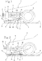
- Figure 2 is a schematic side view, illustrating the operation of the adjustment device 1, while the device 1 adopts a second operating condition of the device 1.
- That aerodynamic load is considered to be positive if acting towards the ground surface S, during that normal forward motion of the motorcar A on the ground surface S itself.
- Normal forward motion includes both the case in which the motion of the motorcar occurs along a straight trajectory and the case in which the motion of the motorcar occurs along any curvilinear trajectory.
- the drag is considered positive if it is directed in the opposite direction to the forward motion.
- Each of the first operating condition and the second operating condition of the device 1 and/or of the motorcar A may therefore occur during any normal forward motion of the motorcar A.
- the first operating condition corresponds to a maximum aerodynamic load configuration for the motorcar A
- the second operating condition corresponds to a minimum aerodynamic load configuration for the motorcar A considering the device 1.
- the first inflow F1 received by the air inlet P is indicated in Figures 1 and 2 .
- the adjustment device 1 comprises a pipe 5 for conveying the flow.
- the pipe 5 is preferably configured to divide the inflow F1 into a first share or first part F11 and into a second share or second part F12.
- the first share F11 of the first flow F1 corresponds to the above-mentioned part of the first flow F1 which is taken in by the diffuser 2 and conveyed towards the diffusion duct 50.
- the second share F12 of the first flow F1 is directed, for example, towards a wheel W of the motorcar A, without passing through the diffuser 2. Therefore, the first share F11 of the first inflow F11 may be defined the "flow taken in”. Therefore, the pipe 5 is configured in such a way that the first share F11 is the flow taken in by the diffuser 2 and the second share F12 is directed towards the wheel W without passing through the diffuser 2.
- the device 1 adopts an operating condition intermediate between the first and the second operating condition.
- the aerodynamic element 3 adopts the first position, the flow taken in F11 is maximised and, consequently, the inflow F1 entering the air inlet P is increased.
- the first operating condition corresponds to that first position of the aerodynamic element 3 and the second operating condition corresponds to that second position of the aerodynamic element 3.
- the movement system 4 is configured to operatively keep, and therefore during that forward motion, that aerodynamic element 3 at that third position.
- the movement system 4 is configured to cause the aerodynamic element 3 to move between the first position and the second position, and therefore from the first position to the second position or vice versa, also preferably passing through the third operating position. Therefore, the movement system 4 is configured to cause the passage of that device 1 and/or of that motorcar from the first operating condition to the second operating condition or vice versa.
- the aerodynamic element 3 moves the internal flow away and/or keeps the internal flow F3 away from the aerodynamic surface 21, so that the third aerodynamic load is intermediate between the first aerodynamic load and the second aerodynamic load.
- the aerodynamic element 3 acts both on the flow taken in F11 and on the second inflow F2, so that the internal flow F3, which results from the combination of the flow taken in F11 and the second inflow F2, is moved away and/or kept away from the aerodynamic surface 21, in such a way that the second aerodynamic load is less than the first aerodynamic load.
- the device 1 is configured in such a way that, when the aerodynamic element 3 adopts the first or the third position, the aerodynamic element 3 occludes that diffusion duct to a lesser degree than when it adopts that second position.
- the degree of occlusion of that diffusion duct is smaller at the first position and at the third position than it is at the second position.
- the device 1 is configured in such a way that, both when the aerodynamic element 3 adopts those first and third positions and when it adopts that second position, the aerodynamic element 3 is located and/or situated, along that diffusion duct 50 and in the direction of that internal flow F3, downstream of that opening 22.
- the aerodynamic element 3 When it adopts the second position, the aerodynamic element 3 has at least two main effects: it increases the pressure on the aerodynamic surface 21, thereby reducing the quantity of flow taken in F11 through the opening 22, and secondly, it moves both the flow taken in F11 and the second inflow F2 away from the aerodynamic surface 21. In that way, when the device adopts the second operating condition, a second aerodynamic load which is less than the above-mentioned first aerodynamic load is generated on the motorcar A.
- the internal flow F3 is kept away from the aerodynamic surface 21 and therefore does not follow the aerodynamic profile of the aerodynamic surface 21.
- the internal flow F3 is practically free to follow the aerodynamic profile of the aerodynamic surface 21, causing a greater diffusing effect by the diffuser 2 on the internal flow F3, and therefore causing the first aerodynamic load to be greater than the second aerodynamic load.
- the opening 22 is preferably located downstream of the radiator R, considering a forward direction of motion of the motorcar A.
- That reduction in the flow rate of the flow taken in F11 results in a reduction in the flow rate through the radiator R in such a way as to reduce the drag of the motorcar A.
- the aerodynamic element 3 acting downstream of the radiator R alters the inflow F1 through the air inlet P with consequent improvement in the drag (when the aerodynamic element 3 is at the second position).
- the device 1 is configured in such a way that the diffusing effect exerted by the diffuser 2 on the internal flow F3 is greater when the aerodynamic element 3 adopts the first position or the third position than when it adopts the second position, so that the first aerodynamic load and the third aerodynamic load are greater than the second aerodynamic load.
- the taking in effect of the diffuser 2 on the first inflow F1 is greater when the aerodynamic element 3 adopts the first position or the third position than when it adopts the second position.
- the aerodynamic element 3 when the aerodynamic element 3 adopts the second position, moving the flow away from the aerodynamic surface 21, the internal flow F3 has a direction such that it avoids those mechanical components of the suspension which would be a source of drag. Therefore, when the aerodynamic element 3 adopts the second position, the drag decreases, compared with when it adopts the first position, which is an advantage in terms of the motorcar maximum velocity and reduction in consumption. Therefore, the second position of the aerodynamic element 3 causes a smaller drag on the motorcar, where drag means the part of aerodynamic force acting in the opposite direction to the forward motion and deriving from the first inflow F1 and from the second inflow F2.
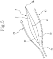
- Figure 5 shows a possible embodiment of the aerodynamic element 3.
- the aerodynamic element has the shape of an aerodynamic flap, and therefore of a wing.
- the aerodynamic element 3 has a first external surface 31.
- the aerodynamic element 3 has a second external surface 32 opposite to the first external surface 31.
- Each of the first external surface 31 and second external surface 32 extends from the leading edge 3a to the trailing edge 3b of the aerodynamic element 3.
- the first external surface 31 is the back side of the flap and the second external surface 32 is the underside of the flap.
- the adjustment device 1 is configured in such a way that, in that first position of the aerodynamic element 3, the aerodynamic element 3 causes the internal flow F3 to follow the profile of the aerodynamic surface 21 of the diffuser 2, both by contact of the internal flow F3 with the first external surface 31, and by contact of the internal flow F3 with the second external surface 32, for example as shown in Figure 5 .
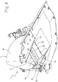
- the movement system 4 comprises an actuator or motor 42.
- the motor 42 acts on the shaft 41 to cause the rotation.
- the above-mentioned movement of the aerodynamic element 3 between the above-mentioned first position and second position is a rotational movement about the axis of the shaft 41.
- the first position, second position and third position of the aerodynamic element 3 differ from each other in the orientation of the aerodynamic element 3 about the axis of the shaft 41 and relative to the diffuser 2 and/or relative to the aerodynamic surface 21.
- first position could also be defined as the first orientation of the aerodynamic element 3 relative to the aerodynamic surface 21 and about the axis of the shaft 41
- second position could also be defined as the second orientation of the aerodynamic element 3 relative to the aerodynamic surface 21 and about the axis of the shaft 41
- third position could also be defined as the third orientation of the aerodynamic element 3 relative to the aerodynamic surface 21 and about the axis of the shaft 41.
- the first and the third orientation of the aerodynamic element 3 cause, compared with the second orientation of the aerodynamic element 3, a greater diffusing effect of the diffuser 2 on the internal flow F3. For this reason, the first and the third aerodynamic load are greater than the second aerodynamic load.
- the first and the third orientation of the aerodynamic element 3, compared with the second orientation of the aerodynamic element 3 also cause an increase in drag due to the greater flow which is directed towards the suspensions of the wheel W.
- the diffuser 2 is as if it were disabled or at least partly disabled. Therefore, the first and the third aerodynamic load are greater than the second aerodynamic load.
- the motor 42 may act directly about a motor-driven axis which coincides with the axis of the shaft 42, without transmission passages transverse to that axis. That greatly simplifies the configuration of the adjustment device 1.
- the adjustment device 1 comprises a structure. That structure shall be considered as defining the aerodynamic surface 21.
- the structure may be built into and/or mounted on an underbody of the motorcar A so that the aerodynamic surface 21 defines a portion of the external underbody surface of the motorcar A.
- the adjustment device 1 could also comprise the air inlet P itself.
- the adjustment device 1 could also comprise the radiator R.
- the radiator R is interposed between the air inlet P and the opening 22, so that the above-mentioned first share F11 of the inflow F1 received by the air inlet P, before entering and being taken in by the diffuser 2, passes through the radiator R. Therefore, at the first position of the aerodynamic element 3, the first share F11 being greater than when the aerodynamic element 3 is at the second position, the cooling effect of the radiator R is greater.
Landscapes
- Engineering & Computer Science (AREA)
- Combustion & Propulsion (AREA)
- Transportation (AREA)
- Mechanical Engineering (AREA)
- Chemical & Material Sciences (AREA)
- Physics & Mathematics (AREA)
- Fluid Mechanics (AREA)
- Cooling, Air Intake And Gas Exhaust, And Fuel Tank Arrangements In Propulsion Units (AREA)
- Structures Of Non-Positive Displacement Pumps (AREA)
- Control Of Multiple Motors (AREA)
- Control Of Direct Current Motors (AREA)
- Protection Of Generators And Motors (AREA)
- Auxiliary Drives, Propulsion Controls, And Safety Devices (AREA)
- Vehicle Body Suspensions (AREA)
- Jet Pumps And Other Pumps (AREA)
- Body Structure For Vehicles (AREA)
Claims (13)
- Verstellvorrichtung zur Steuerung der aerodynamischen Last eines Kraftfahrzeugs (A), umfassend:- einen aerodynamischen Unterbodendiffusor (2), der eine aerodynamische Oberfläche (21) umfasst, die in Verwendung einer Bodenoberfläche (S) hinführend zugewandt ist, und eine Öffnung (22), die durch die aerodynamische Oberfläche (21) ausgebildet ist, wobei der Diffusor (2) in der Lage ist, durch die Öffnung (22) eine angesaugte Strömung (F11) anzusaugen, die mindestens teilweise aus einer Lufteinströmung (F1) definiert ist, die von einem Lufteinlass (P) des Kraftfahrzeugs (A) empfangen und von der Vorwärtsbewegung des Kraftfahrzeugs (A) erzeugt wird, das auf der Bodenoberfläche (S) fährt, sodass der mindestens eine vom Diffusor (2) angesaugte Teil (F11) eine interne Strömung (F3) innerhalb des Diffusors (2) wird, wobei die Vorrichtung (1) so ausgelegt ist, dass die aerodynamische Oberfläche (21) in Verbindung mit der Bodenoberfläche (S) während der Vorwärtsbewegung eine Diffusionsleitung (50) definiert, in der die interne Strömung (F3) strömt, wobei die Verstellvorrichtung Folgendes umfasst:- ein aerodynamisches Element (3), das zwischen einer ersten Position und einer zweiten Position relativ zum Diffusor (2) bewegbar ist;- ein Bewegungssystem (4) zum Bewegen des aerodynamischen Elements (3), dadurch gekennzeichnet, dassdas Bewegungssystem (4) ausgelegt ist, um das aerodynamische Element (3) betriebswirksam zumindest an der ersten und der zweiten Position relativ zum Diffusor (2) zu halten und dafür zu sorgen, dass sich das Element (3) zwischen der ersten und der zweiten Position bewegt,wobei das aerodynamische Element (3) an der ersten Position in die interne Strömung (F3) eingetaucht ist und der internen Strömung (F3) erlaubt, dem aerodynamischen Profil der aerodynamischen Oberfläche (21) zu folgen, sodass eine erste aerodynamische Last erzeugt wird, die während der Vorwärtsbewegung auf das Kraftfahrzeug (A) wirkt,wobei das aerodynamische Element (3) an der zweiten Position mindestens teilweise als Barriere gegen die interne Strömung (F3) wirkt und die interne Strömung (F3) wegführend von der aerodynamischen Oberfläche (21) bewegt, sodass eine zweite aerodynamische Last erzeugt wird, die während der Vorwärtsbewegung auf das Kraftfahrzeug wirkt, wobei die Vorrichtung (1) so ausgelegt ist, dass die zweite aerodynamische Last kleiner ist als die erste aerodynamische Last.
- Verstellvorrichtung nach Anspruch 1, die so ausgelegt ist, dass das aerodynamische Element (3), wenn das aerodynamische Element (3) die erste Position einnimmt, auf die Diffusionsleitung (50) einen Verschließeffekt ausübt, der kleiner ist, als wenn es die zweite Position einnimmt, sodass der Diffusionseffekt, den der Diffusor (2) auf die interne Strömung (F3) mittels der aerodynamischen Oberfläche (21) ausübt, an der ersten Position größer ist als an der zweiten Position und die erste aerodynamische Last größer ist als die zweite aerodynamische Last,- wobei die Verstellvorrichtung so ausgelegt ist, dass das aerodynamische Element (3) sowohl an der ersten Position als auch an der zweiten Position nach der Öffnung (22) entlang der Diffusionsleitung und in Richtung der internen Strömung (F3) befindlich ist.
- Verstellvorrichtung nach Anspruch 1 oder 2, wobei- das aerodynamische Element (3) eine erste externe Oberfläche (31) und eine zweite externe Oberfläche (32) aufweist, die gegenständig zur ersten externen Oberfläche (32) angeordnet ist, die sich jeweils von der Vorderkante (3a) zur Hinterkante (3b) des aerodynamischen Elements (3) erstrecken;- das aerodynamische Element (3) an der ersten Position dafür sorgt, dass die interne Strömung (F3) dem Profil der aerodynamischen Oberfläche (21) des Diffusors (2) sowohl durch den Kontakt der internen Strömung (F3) mit der ersten externen Oberfläche (31) als auch durch den Kontakt der internen Strömung (F3) mit der zweiten externen Oberfläche (32) folgt.
- Verstellvorrichtung nach Anspruch 3, wobei das aerodynamische Element (3) die Form eines Flügels aufweist, wobei die erste externe Oberfläche (31) die Rückseite des Flügels und die zweite externe Oberfläche (32) die Unterseite des Flügels ist.
- Verstellvorrichtung nach einem oder mehreren der vorhergehenden Ansprüche, wobei das Bewegungssystem (4) Folgendes umfasst:- eine Welle (41), auf der das aerodynamische Element (3) montiert ist, sodass das aerodynamische Element (3) sich fest verbunden mit der Welle (41) um die Achse der Welle (41) dreht;- einen Steller (42), der auf die Welle (41) wirkt, um die Drehung zu veranlassen, sodass die Bewegung des aerodynamischen Elements (3) eine Drehbewegung um die Achse ist, wobei sich die erste Position und die zweite Position hinsichtlich der Ausrichtung des aerodynamischen Elements (3) um die Achse voneinander unterscheiden.
- Verstellvorrichtung nach Anspruch 4 und 5, wobei die Welle (41) zwischen der Vorderkante (3a) und der Hinterkante (3b) des aerodynamischen Elements (3) platziert und entlang der Diffusionsleitung (50) und in der Richtung der internen Strömung (F3) nach der Öffnung (22) positioniert ist.
- Verstellvorrichtung nach Anspruch 2 und Anspruch 5 oder 6, wobei- der Diffusor (2) zwei seitliche Oberflächen (23, 24) umfasst, die sich quer zur aerodynamischen Oberfläche (21) erstrecken, um die Seiten der Diffusionsleitung zu begrenzen, wobei die Welle (41) von den seitlichen Oberflächen (23, 24) gestützt wird;- die aerodynamische Oberfläche (21) die Oberseite der Diffusionsleitung begrenzt;- die Welle (41) innerhalb der Diffusionsleitung positioniert ist, sodass das aerodynamische Element (3) sowohl an der ersten als auch der zweiten Position innerhalb der Diffusionsleitung nach der Öffnung (22) entlang der Diffusionsleitung und in der Richtung der internen Strömung (F3) platziert ist.
- Verstellvorrichtung nach einem oder mehreren der vorhergehenden Ansprüche, umfassend eine Struktur, die die aerodynamische Oberfläche (21) definiert, wobei diese Struktur in der Lage ist, in einen Unterboden des Kraftfahrzeugs (A) eingebaut oder auf diesem montiert zu werden, sodass die aerodynamische Oberfläche (21) einen Abschnitt der externen Unterbodenoberfläche des Kraftfahrzeugs (A) definiert.
- Verstellvorrichtung nach einem oder mehreren der vorhergehenden Ansprüche, umfassend den Lufteinlass (P).
- Verstellvorrichtung nach einem der vorhergehenden Ansprüche, wobei das Bewegungssystem (4) ausgelegt ist, um das aerodynamische Element (3) betriebswirksam zumindest an einer dritten Position relativ zum Diffusor (2) zu halten und dafür zu sorgen, dass sich das Element (3) zwischen der ersten Position oder zweiten Position und der dritten Position bewegt, wobei die dritte Position eine Zwischenposition zwischen der ersten und der zweiten Position ist.
- Kraftfahrzeug (A), umfassend eine Verstellvorrichtung (1) nach einem oder mehreren der vorhergehenden Ansprüche, wobei die aerodynamische Oberfläche (21) des Diffusors (2) einen Abschnitt einer externen Unterbodenoberfläche des Kraftfahrzeugs (A) definiert.
- Kraftfahrzeug nach Anspruch 11, umfassend den Lufteinlass und einen Kühler (R), der zwischen dem Lufteinlass (P) und der Öffnung (22) eingesetzt ist, sodass die angesaugte Strömung (F11) durch den Kühler (R) strömt, wobei die angesaugte Strömung (F11), wenn sich das aerodynamische Element (3) an der zweiten Position befindet, kleiner ist als die angesaugte Strömung (F11), wenn sich das aerodynamische Element (3) an der ersten Position befindet, wobei eine Reduktion der angesaugten Strömung (F11) mit einem Wechsel des aerodynamischen Elements (3) von der ersten Position in die zweite Position definiert wird, wobei die Reduktion der angesaugten Strömung (F11) eine Reduktion der Durchflussmenge der Hauptströmung (F1) durch den Kühler (R) bewirkt, sodass der Strömungswiderstand des Kraftfahrzeugs (A) reduziert wird.
- Kraftfahrzeug nach Anspruch 11 oder 12, wobei die Verstellvorrichtung vor einem Vorderrad (W) des Kraftfahrzeugs (A) platziert ist.
Priority Applications (2)
| Application Number | Priority Date | Filing Date | Title |
|---|---|---|---|
| HRP20230076TT HRP20230076T1 (hr) | 2018-10-18 | 2019-10-11 | Uređaj za podešavanje za kontrolu aerodinamičnog opterećenja na motornom automobilu |
| SI201930427T SI3867129T1 (sl) | 2018-10-18 | 2019-10-11 | Regulacijska naprava za kontrolo aerodinamične obremenitve avtomobila |
Applications Claiming Priority (2)
| Application Number | Priority Date | Filing Date | Title |
|---|---|---|---|
| IT102018000009561A IT201800009561A1 (it) | 2018-10-18 | 2018-10-18 | Dispositivo regolatore di carico aerodinamico per automobile |
| PCT/IB2019/058679 WO2020079545A1 (en) | 2018-10-18 | 2019-10-11 | Adjustment device for controlling the aerodynamic load on a motorcar |
Publications (2)
| Publication Number | Publication Date |
|---|---|
| EP3867129A1 EP3867129A1 (de) | 2021-08-25 |
| EP3867129B1 true EP3867129B1 (de) | 2022-12-07 |
Family
ID=65199483
Family Applications (1)
| Application Number | Title | Priority Date | Filing Date |
|---|---|---|---|
| EP19797151.8A Active EP3867129B1 (de) | 2018-10-18 | 2019-10-11 | Verstellvorrichtung zur steuerung der aerodynamischen last eines kraftfahrzeugs |
Country Status (11)
| Country | Link |
|---|---|
| US (1) | US11702152B2 (de) |
| EP (1) | EP3867129B1 (de) |
| JP (1) | JP7329591B2 (de) |
| CN (1) | CN112839860B (de) |
| AU (1) | AU2019361340B2 (de) |
| CA (1) | CA3111905A1 (de) |
| ES (1) | ES2937966T3 (de) |
| HR (1) | HRP20230076T1 (de) |
| IT (1) | IT201800009561A1 (de) |
| SI (1) | SI3867129T1 (de) |
| WO (1) | WO2020079545A1 (de) |
Families Citing this family (1)
| Publication number | Priority date | Publication date | Assignee | Title |
|---|---|---|---|---|
| WO2025036540A1 (en) * | 2023-08-13 | 2025-02-20 | Salem Gamal Ibrahim Ali | Aero brake |
Family Cites Families (33)
| Publication number | Priority date | Publication date | Assignee | Title |
|---|---|---|---|---|
| DE3735921C1 (de) * | 1987-10-23 | 1988-12-01 | Audi Ag | Vorrichtung zur Beeinflussung des Kuehlluftstroms an einem Kraftfahrzeug |
| JP2780418B2 (ja) * | 1989-06-15 | 1998-07-30 | 株式会社デンソー | 車両用フロントスポイラー装置 |
| DE10048531C1 (de) * | 2000-09-30 | 2002-04-25 | Porsche Ag | Kühlluftführung für Kraftfahrzeuge |
| EP2174818B1 (de) * | 2008-10-08 | 2011-04-20 | C.R.F. Società Consortile per Azioni | System zu Steuerung und Führung des Luftstroms durch den Motorraum eines Fahrzeuges |
| DE102009050967A1 (de) * | 2009-10-28 | 2011-05-05 | Daimler Ag | Luftleitungs-Kühlsystem für eine Kraftfahrzeugbremse und Verfahren zur Bereitstellung eines variablen Kühlluftstroms |
| KR20110062079A (ko) * | 2009-12-02 | 2011-06-10 | 현대자동차주식회사 | 차량 엔진룸 공기저항안정화장치 |
| US8210600B1 (en) * | 2011-01-05 | 2012-07-03 | Ford Global Technologies, Llc | Aerodynamic package for an automotive vehicle |
| US8479853B2 (en) * | 2011-05-17 | 2013-07-09 | GM Global Technology Operations LLC | Control of an airstream flow rate through a covered compartment by an adjustable shutter |
| JP5655952B2 (ja) * | 2011-10-12 | 2015-01-21 | トヨタ自動車株式会社 | 車両前部構造 |
| DE102011056663B4 (de) * | 2011-12-20 | 2022-05-12 | Dr. Ing. H.C. F. Porsche Aktiengesellschaft | Vorrichtung zur Kühlluftzuführung mit einer Kühlluftsteuerung |
| US8887845B2 (en) * | 2012-09-14 | 2014-11-18 | GM Global Technology Operations LLC | Stow-away air dam |
| GB201216941D0 (en) * | 2012-09-21 | 2012-11-07 | Mclaren Automotive Ltd | Devices for controlling the down force generated by a vehicle |
| DE102013105843B4 (de) * | 2013-06-06 | 2022-08-04 | Dr. Ing. H.C. F. Porsche Aktiengesellschaft | Kraftfahrzeug mit einem verstellbaren Luftleitelement |
| JP6060916B2 (ja) * | 2014-02-12 | 2017-01-18 | マツダ株式会社 | 自動車の前部整流構造 |
| GB2529151B (en) * | 2014-08-05 | 2018-11-07 | Jaguar Land Rover Ltd | Modifying aerodynamic performance of a vehicle |
| DE102014111074B4 (de) * | 2014-08-05 | 2025-11-20 | Dr. Ing. H.C. F. Porsche Aktiengesellschaft | Kraftfahrzeug |
| FR3029849B1 (fr) * | 2014-12-10 | 2018-04-13 | Psa Automobiles Sa. | Dispositif de deflexion d’air a paroi a rotation controlee par des ressorts antagonistes dont l’un est deformable par effet joule |
| DE102014118631A1 (de) * | 2014-12-15 | 2016-06-16 | Dr. Ing. H.C. F. Porsche Aktiengesellschaft | Kühlluftzufuhrvorrichtung für ein Kraftfahrzeug |
| US10351181B2 (en) * | 2015-03-18 | 2019-07-16 | Honda Motor Co., Ltd. | Apparatus and methods for manipulating airflow around and through a vehicle |
| JP6512552B2 (ja) * | 2015-07-03 | 2019-05-15 | 株式会社Subaru | エンジン房空気誘導体 |
| US9902438B2 (en) * | 2015-11-30 | 2018-02-27 | GM Global Technology Operations LLC | Selective control of vehicle aerodynamics |
| US9669885B1 (en) * | 2015-12-04 | 2017-06-06 | GM Global Technology Operations LLC | Regulation of downforce on a vehicle body via control of an airstream through a vehicle duct |
| FR3044998B1 (fr) * | 2015-12-10 | 2018-03-23 | Valeo Systemes Thermiques | Dispositif deflecteur aerodynamique pour roue de vehicule automobile |
| US9902439B2 (en) * | 2016-01-04 | 2018-02-27 | GM Global Technology Operations LLC | Control of airflow relative to a vehicle via active underbody panel(s) |
| DE102016116458A1 (de) * | 2016-01-21 | 2017-07-27 | Dr. Ing. H.C. F. Porsche Aktiengesellschaft | Bug eines Kraftfahrzeugs |
| JP2017149328A (ja) * | 2016-02-25 | 2017-08-31 | トヨタ自動車株式会社 | 可動式フロントスポイラ装置 |
| JP2017165196A (ja) * | 2016-03-15 | 2017-09-21 | 三菱自動車工業株式会社 | 車両の前部構造 |
| DE102016108294A1 (de) * | 2016-05-04 | 2017-11-09 | Deutsches Zentrum für Luft- und Raumfahrt e.V. | Luftkühlsystem |
| JP6734725B2 (ja) * | 2016-08-01 | 2020-08-05 | 株式会社Subaru | 車両用空気流制御装置 |
| DE102016214834A1 (de) * | 2016-08-10 | 2018-02-15 | Volkswagen Aktiengesellschaft | Heckspoiler und Fahrzeug mit einem derartigen Heckspoiler |
| DE102017103881A1 (de) * | 2017-02-24 | 2018-08-30 | Dr. Ing. H.C. F. Porsche Aktiengesellschaft | Kraftfahrzeug mit frontseitigem Diffusor |
| CN206856487U (zh) * | 2017-06-28 | 2018-01-09 | 北京新能源汽车股份有限公司 | 一种热管理舱、发动机舱及电动汽车 |
| US10457341B2 (en) * | 2018-03-21 | 2019-10-29 | GM Global Technology Operations LLC | Underbody channel vortex generators |
-
2018
- 2018-10-18 IT IT102018000009561A patent/IT201800009561A1/it unknown
-
2019
- 2019-10-11 CA CA3111905A patent/CA3111905A1/en active Pending
- 2019-10-11 HR HRP20230076TT patent/HRP20230076T1/hr unknown
- 2019-10-11 US US17/280,470 patent/US11702152B2/en active Active
- 2019-10-11 JP JP2021521165A patent/JP7329591B2/ja active Active
- 2019-10-11 EP EP19797151.8A patent/EP3867129B1/de active Active
- 2019-10-11 SI SI201930427T patent/SI3867129T1/sl unknown
- 2019-10-11 AU AU2019361340A patent/AU2019361340B2/en active Active
- 2019-10-11 CN CN201980067759.2A patent/CN112839860B/zh active Active
- 2019-10-11 WO PCT/IB2019/058679 patent/WO2020079545A1/en not_active Ceased
- 2019-10-11 ES ES19797151T patent/ES2937966T3/es active Active
Also Published As
| Publication number | Publication date |
|---|---|
| JP7329591B2 (ja) | 2023-08-18 |
| US11702152B2 (en) | 2023-07-18 |
| IT201800009561A1 (it) | 2020-04-18 |
| EP3867129A1 (de) | 2021-08-25 |
| SI3867129T1 (sl) | 2023-04-28 |
| US20220033008A1 (en) | 2022-02-03 |
| CA3111905A1 (en) | 2020-04-23 |
| AU2019361340A1 (en) | 2021-04-01 |
| AU2019361340B2 (en) | 2024-09-12 |
| WO2020079545A1 (en) | 2020-04-23 |
| ES2937966T3 (es) | 2023-04-03 |
| HRP20230076T1 (hr) | 2023-03-17 |
| CN112839860A (zh) | 2021-05-25 |
| JP2022505214A (ja) | 2022-01-14 |
| CN112839860B (zh) | 2023-04-25 |
Similar Documents
| Publication | Publication Date | Title |
|---|---|---|
| US10173768B2 (en) | High-lift flap, arrangement of a high-lift flap together with a device for influencing the flow on the same and aircraft comprising said arrangement | |
| US9994100B1 (en) | Shutter control arrangement for a vehicle | |
| US7757643B2 (en) | Device for regulating an air flow for engine cooling | |
| JP5004254B2 (ja) | 自動車のためのフロント部分 | |
| US20170101140A1 (en) | Adjustable component cooling device for controlling downforce generated by a vehicle | |
| US20090266312A1 (en) | Cooling Device | |
| US20140370795A1 (en) | Vehicle speed controlled active grille shutter system | |
| JP6549696B2 (ja) | 車輌の空力性能の変更 | |
| KR102731552B1 (ko) | 액티브 에어플랩 | |
| CN103998272A (zh) | 空气输入调节装置 | |
| US8512111B2 (en) | Vehicle cowl box structure | |
| WO2013186130A1 (en) | Airflow control system | |
| EP3867129B1 (de) | Verstellvorrichtung zur steuerung der aerodynamischen last eines kraftfahrzeugs | |
| CN110615043B (zh) | 气流引导组件 | |
| US20180354558A1 (en) | Fuel cell vehicle | |
| JP5610558B2 (ja) | 航空機のキャビンの内圧を制御するためのバルブ | |
| US4246918A (en) | Method and apparatus for forced air balancing of damper blades | |
| JP2015513037A (ja) | 流体循環バルブ | |
| CN110248835B (zh) | 用于调节在车辆的发动机罩下方流动的气流的装置 | |
| US11654979B1 (en) | Passively activated flow control device for a vehicle | |
| CN110901375A (zh) | 用于机动车辆的冷却空气供应设备 | |
| US6626142B2 (en) | Intake air rate controlling device for an internal combustion engine | |
| JP3780600B2 (ja) | 温水式暖房装置 | |
| JP2026512376A (ja) | 車両および方法 | |
| GB2636818A (en) | A diffuser for a vehicle |
Legal Events
| Date | Code | Title | Description |
|---|---|---|---|
| REG | Reference to a national code |
Ref country code: HR Ref legal event code: TUEP Ref document number: P20230076T Country of ref document: HR |
|
| STAA | Information on the status of an ep patent application or granted ep patent |
Free format text: STATUS: UNKNOWN |
|
| STAA | Information on the status of an ep patent application or granted ep patent |
Free format text: STATUS: THE INTERNATIONAL PUBLICATION HAS BEEN MADE |
|
| PUAI | Public reference made under article 153(3) epc to a published international application that has entered the european phase |
Free format text: ORIGINAL CODE: 0009012 |
|
| STAA | Information on the status of an ep patent application or granted ep patent |
Free format text: STATUS: REQUEST FOR EXAMINATION WAS MADE |
|
| 17P | Request for examination filed |
Effective date: 20210414 |
|
| AK | Designated contracting states |
Kind code of ref document: A1 Designated state(s): AL AT BE BG CH CY CZ DE DK EE ES FI FR GB GR HR HU IE IS IT LI LT LU LV MC MK MT NL NO PL PT RO RS SE SI SK SM TR |
|
| DAV | Request for validation of the european patent (deleted) | ||
| DAX | Request for extension of the european patent (deleted) | ||
| GRAP | Despatch of communication of intention to grant a patent |
Free format text: ORIGINAL CODE: EPIDOSNIGR1 |
|
| STAA | Information on the status of an ep patent application or granted ep patent |
Free format text: STATUS: GRANT OF PATENT IS INTENDED |
|
| INTG | Intention to grant announced |
Effective date: 20220520 |
|
| GRAS | Grant fee paid |
Free format text: ORIGINAL CODE: EPIDOSNIGR3 |
|
| GRAA | (expected) grant |
Free format text: ORIGINAL CODE: 0009210 |
|
| STAA | Information on the status of an ep patent application or granted ep patent |
Free format text: STATUS: THE PATENT HAS BEEN GRANTED |
|
| AK | Designated contracting states |
Kind code of ref document: B1 Designated state(s): AL AT BE BG CH CY CZ DE DK EE ES FI FR GB GR HR HU IE IS IT LI LT LU LV MC MK MT NL NO PL PT RO RS SE SI SK SM TR |
|
| REG | Reference to a national code |
Ref country code: GB Ref legal event code: FG4D |
|
| REG | Reference to a national code |
Ref country code: CH Ref legal event code: EP Ref country code: AT Ref legal event code: REF Ref document number: 1536156 Country of ref document: AT Kind code of ref document: T Effective date: 20221215 |
|
| REG | Reference to a national code |
Ref country code: DE Ref legal event code: R096 Ref document number: 602019022946 Country of ref document: DE |
|
| REG | Reference to a national code |
Ref country code: IE Ref legal event code: FG4D |
|
| REG | Reference to a national code |
Ref country code: RO Ref legal event code: EPE |
|
| REG | Reference to a national code |
Ref country code: SE Ref legal event code: TRGR |
|
| REG | Reference to a national code |
Ref country code: HR Ref legal event code: T1PR Ref document number: P20230076 Country of ref document: HR |
|
| REG | Reference to a national code |
Ref country code: LT Ref legal event code: MG9D |
|
| REG | Reference to a national code |
Ref country code: ES Ref legal event code: FG2A Ref document number: 2937966 Country of ref document: ES Kind code of ref document: T3 Effective date: 20230403 |
|
| REG | Reference to a national code |
Ref country code: NL Ref legal event code: MP Effective date: 20221207 |
|
| PG25 | Lapsed in a contracting state [announced via postgrant information from national office to epo] |
Ref country code: NO Free format text: LAPSE BECAUSE OF FAILURE TO SUBMIT A TRANSLATION OF THE DESCRIPTION OR TO PAY THE FEE WITHIN THE PRESCRIBED TIME-LIMIT Effective date: 20230307 Ref country code: LT Free format text: LAPSE BECAUSE OF FAILURE TO SUBMIT A TRANSLATION OF THE DESCRIPTION OR TO PAY THE FEE WITHIN THE PRESCRIBED TIME-LIMIT Effective date: 20221207 Ref country code: FI Free format text: LAPSE BECAUSE OF FAILURE TO SUBMIT A TRANSLATION OF THE DESCRIPTION OR TO PAY THE FEE WITHIN THE PRESCRIBED TIME-LIMIT Effective date: 20221207 |
|
| PG25 | Lapsed in a contracting state [announced via postgrant information from national office to epo] |
Ref country code: RS Free format text: LAPSE BECAUSE OF FAILURE TO SUBMIT A TRANSLATION OF THE DESCRIPTION OR TO PAY THE FEE WITHIN THE PRESCRIBED TIME-LIMIT Effective date: 20221207 Ref country code: PL Free format text: LAPSE BECAUSE OF FAILURE TO SUBMIT A TRANSLATION OF THE DESCRIPTION OR TO PAY THE FEE WITHIN THE PRESCRIBED TIME-LIMIT Effective date: 20221207 Ref country code: LV Free format text: LAPSE BECAUSE OF FAILURE TO SUBMIT A TRANSLATION OF THE DESCRIPTION OR TO PAY THE FEE WITHIN THE PRESCRIBED TIME-LIMIT Effective date: 20221207 Ref country code: GR Free format text: LAPSE BECAUSE OF FAILURE TO SUBMIT A TRANSLATION OF THE DESCRIPTION OR TO PAY THE FEE WITHIN THE PRESCRIBED TIME-LIMIT Effective date: 20230308 |
|
| P01 | Opt-out of the competence of the unified patent court (upc) registered |
Effective date: 20230524 |
|
| PG25 | Lapsed in a contracting state [announced via postgrant information from national office to epo] |
Ref country code: NL Free format text: LAPSE BECAUSE OF FAILURE TO SUBMIT A TRANSLATION OF THE DESCRIPTION OR TO PAY THE FEE WITHIN THE PRESCRIBED TIME-LIMIT Effective date: 20221207 |
|
| PG25 | Lapsed in a contracting state [announced via postgrant information from national office to epo] |
Ref country code: SM Free format text: LAPSE BECAUSE OF FAILURE TO SUBMIT A TRANSLATION OF THE DESCRIPTION OR TO PAY THE FEE WITHIN THE PRESCRIBED TIME-LIMIT Effective date: 20221207 Ref country code: PT Free format text: LAPSE BECAUSE OF FAILURE TO SUBMIT A TRANSLATION OF THE DESCRIPTION OR TO PAY THE FEE WITHIN THE PRESCRIBED TIME-LIMIT Effective date: 20230410 Ref country code: EE Free format text: LAPSE BECAUSE OF FAILURE TO SUBMIT A TRANSLATION OF THE DESCRIPTION OR TO PAY THE FEE WITHIN THE PRESCRIBED TIME-LIMIT Effective date: 20221207 Ref country code: CZ Free format text: LAPSE BECAUSE OF FAILURE TO SUBMIT A TRANSLATION OF THE DESCRIPTION OR TO PAY THE FEE WITHIN THE PRESCRIBED TIME-LIMIT Effective date: 20221207 |
|
| PG25 | Lapsed in a contracting state [announced via postgrant information from national office to epo] |
Ref country code: SK Free format text: LAPSE BECAUSE OF FAILURE TO SUBMIT A TRANSLATION OF THE DESCRIPTION OR TO PAY THE FEE WITHIN THE PRESCRIBED TIME-LIMIT Effective date: 20221207 Ref country code: IS Free format text: LAPSE BECAUSE OF FAILURE TO SUBMIT A TRANSLATION OF THE DESCRIPTION OR TO PAY THE FEE WITHIN THE PRESCRIBED TIME-LIMIT Effective date: 20230407 Ref country code: AL Free format text: LAPSE BECAUSE OF FAILURE TO SUBMIT A TRANSLATION OF THE DESCRIPTION OR TO PAY THE FEE WITHIN THE PRESCRIBED TIME-LIMIT Effective date: 20221207 |
|
| REG | Reference to a national code |
Ref country code: DE Ref legal event code: R097 Ref document number: 602019022946 Country of ref document: DE |
|
| PLBE | No opposition filed within time limit |
Free format text: ORIGINAL CODE: 0009261 |
|
| REG | Reference to a national code |
Ref country code: HR Ref legal event code: ODRP Ref document number: P20230076 Country of ref document: HR Payment date: 20230926 Year of fee payment: 5 |
|
| STAA | Information on the status of an ep patent application or granted ep patent |
Free format text: STATUS: NO OPPOSITION FILED WITHIN TIME LIMIT |
|
| PG25 | Lapsed in a contracting state [announced via postgrant information from national office to epo] |
Ref country code: DK Free format text: LAPSE BECAUSE OF FAILURE TO SUBMIT A TRANSLATION OF THE DESCRIPTION OR TO PAY THE FEE WITHIN THE PRESCRIBED TIME-LIMIT Effective date: 20221207 |
|
| 26N | No opposition filed |
Effective date: 20230908 |
|
| REG | Reference to a national code |
Ref country code: AT Ref legal event code: UEP Ref document number: 1536156 Country of ref document: AT Kind code of ref document: T Effective date: 20221207 |
|
| PG25 | Lapsed in a contracting state [announced via postgrant information from national office to epo] |
Ref country code: MC Free format text: LAPSE BECAUSE OF FAILURE TO SUBMIT A TRANSLATION OF THE DESCRIPTION OR TO PAY THE FEE WITHIN THE PRESCRIBED TIME-LIMIT Effective date: 20221207 |
|
| REG | Reference to a national code |
Ref country code: BE Ref legal event code: MM Effective date: 20231031 |
|
| PG25 | Lapsed in a contracting state [announced via postgrant information from national office to epo] |
Ref country code: LU Free format text: LAPSE BECAUSE OF NON-PAYMENT OF DUE FEES Effective date: 20231011 |
|
| PG25 | Lapsed in a contracting state [announced via postgrant information from national office to epo] |
Ref country code: LU Free format text: LAPSE BECAUSE OF NON-PAYMENT OF DUE FEES Effective date: 20231011 |
|
| PG25 | Lapsed in a contracting state [announced via postgrant information from national office to epo] |
Ref country code: BE Free format text: LAPSE BECAUSE OF NON-PAYMENT OF DUE FEES Effective date: 20231031 |
|
| PG25 | Lapsed in a contracting state [announced via postgrant information from national office to epo] |
Ref country code: IE Free format text: LAPSE BECAUSE OF NON-PAYMENT OF DUE FEES Effective date: 20231011 |
|
| REG | Reference to a national code |
Ref country code: HR Ref legal event code: ODRP Ref document number: P20230076 Country of ref document: HR Payment date: 20240923 Year of fee payment: 6 |
|
| PG25 | Lapsed in a contracting state [announced via postgrant information from national office to epo] |
Ref country code: IE Free format text: LAPSE BECAUSE OF NON-PAYMENT OF DUE FEES Effective date: 20231011 |
|
| PG25 | Lapsed in a contracting state [announced via postgrant information from national office to epo] |
Ref country code: BG Free format text: LAPSE BECAUSE OF FAILURE TO SUBMIT A TRANSLATION OF THE DESCRIPTION OR TO PAY THE FEE WITHIN THE PRESCRIBED TIME-LIMIT Effective date: 20221207 |
|
| PG25 | Lapsed in a contracting state [announced via postgrant information from national office to epo] |
Ref country code: BG Free format text: LAPSE BECAUSE OF FAILURE TO SUBMIT A TRANSLATION OF THE DESCRIPTION OR TO PAY THE FEE WITHIN THE PRESCRIBED TIME-LIMIT Effective date: 20221207 |
|
| PGFP | Annual fee paid to national office [announced via postgrant information from national office to epo] |
Ref country code: SI Payment date: 20240923 Year of fee payment: 6 |
|
| PG25 | Lapsed in a contracting state [announced via postgrant information from national office to epo] |
Ref country code: CY Free format text: LAPSE BECAUSE OF FAILURE TO SUBMIT A TRANSLATION OF THE DESCRIPTION OR TO PAY THE FEE WITHIN THE PRESCRIBED TIME-LIMIT; INVALID AB INITIO Effective date: 20191011 |
|
| PG25 | Lapsed in a contracting state [announced via postgrant information from national office to epo] |
Ref country code: HU Free format text: LAPSE BECAUSE OF FAILURE TO SUBMIT A TRANSLATION OF THE DESCRIPTION OR TO PAY THE FEE WITHIN THE PRESCRIBED TIME-LIMIT; INVALID AB INITIO Effective date: 20191011 |
|
| PGFP | Annual fee paid to national office [announced via postgrant information from national office to epo] |
Ref country code: HR Payment date: 20250923 Year of fee payment: 7 |
|
| REG | Reference to a national code |
Ref country code: HR Ref legal event code: ODRP Ref document number: P20230076 Country of ref document: HR Payment date: 20250923 Year of fee payment: 7 |
|
| REG | Reference to a national code |
Ref country code: CH Ref legal event code: U11 Free format text: ST27 STATUS EVENT CODE: U-0-0-U10-U11 (AS PROVIDED BY THE NATIONAL OFFICE) Effective date: 20251101 |
|
| PG25 | Lapsed in a contracting state [announced via postgrant information from national office to epo] |
Ref country code: TR Free format text: LAPSE BECAUSE OF FAILURE TO SUBMIT A TRANSLATION OF THE DESCRIPTION OR TO PAY THE FEE WITHIN THE PRESCRIBED TIME-LIMIT Effective date: 20221207 |
|
| PGFP | Annual fee paid to national office [announced via postgrant information from national office to epo] |
Ref country code: DE Payment date: 20251028 Year of fee payment: 7 |
|
| PGFP | Annual fee paid to national office [announced via postgrant information from national office to epo] |
Ref country code: GB Payment date: 20251023 Year of fee payment: 7 |
|
| PGFP | Annual fee paid to national office [announced via postgrant information from national office to epo] |
Ref country code: AT Payment date: 20250917 Year of fee payment: 7 |
|
| PGFP | Annual fee paid to national office [announced via postgrant information from national office to epo] |
Ref country code: IT Payment date: 20251028 Year of fee payment: 7 |
|
| PGFP | Annual fee paid to national office [announced via postgrant information from national office to epo] |
Ref country code: FR Payment date: 20251027 Year of fee payment: 7 |
|
| PGFP | Annual fee paid to national office [announced via postgrant information from national office to epo] |
Ref country code: CH Payment date: 20251101 Year of fee payment: 7 Ref country code: SE Payment date: 20251024 Year of fee payment: 7 |
|
| PGFP | Annual fee paid to national office [announced via postgrant information from national office to epo] |
Ref country code: RO Payment date: 20251002 Year of fee payment: 7 |
|
| PGFP | Annual fee paid to national office [announced via postgrant information from national office to epo] |
Ref country code: ES Payment date: 20251118 Year of fee payment: 7 |