EP3863347B1 - Ressourcenkonfigurationsverfahren und -vorrichtung - Google Patents
Ressourcenkonfigurationsverfahren und -vorrichtung Download PDFInfo
- Publication number
- EP3863347B1 EP3863347B1 EP19878021.5A EP19878021A EP3863347B1 EP 3863347 B1 EP3863347 B1 EP 3863347B1 EP 19878021 A EP19878021 A EP 19878021A EP 3863347 B1 EP3863347 B1 EP 3863347B1
- Authority
- EP
- European Patent Office
- Prior art keywords
- terminal
- information
- resource
- slot
- sidelink
- Prior art date
- Legal status (The legal status is an assumption and is not a legal conclusion. Google has not performed a legal analysis and makes no representation as to the accuracy of the status listed.)
- Active
Links
Images


Classifications
-
- H—ELECTRICITY
- H04—ELECTRIC COMMUNICATION TECHNIQUE
- H04L—TRANSMISSION OF DIGITAL INFORMATION, e.g. TELEGRAPHIC COMMUNICATION
- H04L5/00—Arrangements affording multiple use of the transmission path
- H04L5/22—Arrangements affording multiple use of the transmission path using time-division multiplexing
- H04L5/26—Arrangements affording multiple use of the transmission path using time-division multiplexing combined with the use of different frequencies
-
- H—ELECTRICITY
- H04—ELECTRIC COMMUNICATION TECHNIQUE
- H04L—TRANSMISSION OF DIGITAL INFORMATION, e.g. TELEGRAPHIC COMMUNICATION
- H04L5/00—Arrangements affording multiple use of the transmission path
- H04L5/003—Arrangements for allocating sub-channels of the transmission path
- H04L5/0053—Allocation of signalling, i.e. of overhead other than pilot signals
-
- H—ELECTRICITY
- H04—ELECTRIC COMMUNICATION TECHNIQUE
- H04L—TRANSMISSION OF DIGITAL INFORMATION, e.g. TELEGRAPHIC COMMUNICATION
- H04L5/00—Arrangements affording multiple use of the transmission path
- H04L5/0091—Signalling for the administration of the divided path, e.g. signalling of configuration information
- H04L5/0094—Indication of how sub-channels of the path are allocated
-
- H—ELECTRICITY
- H04—ELECTRIC COMMUNICATION TECHNIQUE
- H04W—WIRELESS COMMUNICATION NETWORKS
- H04W72/00—Local resource management
- H04W72/04—Wireless resource allocation
- H04W72/044—Wireless resource allocation based on the type of the allocated resource
- H04W72/0446—Resources in time domain, e.g. slots or frames
-
- H—ELECTRICITY
- H04—ELECTRIC COMMUNICATION TECHNIQUE
- H04W—WIRELESS COMMUNICATION NETWORKS
- H04W72/00—Local resource management
- H04W72/04—Wireless resource allocation
- H04W72/044—Wireless resource allocation based on the type of the allocated resource
- H04W72/0453—Resources in frequency domain, e.g. a carrier in FDMA
-
- H—ELECTRICITY
- H04—ELECTRIC COMMUNICATION TECHNIQUE
- H04W—WIRELESS COMMUNICATION NETWORKS
- H04W72/00—Local resource management
- H04W72/20—Control channels or signalling for resource management
-
- H—ELECTRICITY
- H04—ELECTRIC COMMUNICATION TECHNIQUE
- H04W—WIRELESS COMMUNICATION NETWORKS
- H04W72/00—Local resource management
- H04W72/20—Control channels or signalling for resource management
- H04W72/23—Control channels or signalling for resource management in the downlink direction of a wireless link, i.e. towards a terminal
-
- H—ELECTRICITY
- H04—ELECTRIC COMMUNICATION TECHNIQUE
- H04W—WIRELESS COMMUNICATION NETWORKS
- H04W4/00—Services specially adapted for wireless communication networks; Facilities therefor
- H04W4/30—Services specially adapted for particular environments, situations or purposes
- H04W4/40—Services specially adapted for particular environments, situations or purposes for vehicles, e.g. vehicle-to-pedestrians [V2P]
-
- H—ELECTRICITY
- H04—ELECTRIC COMMUNICATION TECHNIQUE
- H04W—WIRELESS COMMUNICATION NETWORKS
- H04W4/00—Services specially adapted for wireless communication networks; Facilities therefor
- H04W4/70—Services for machine-to-machine communication [M2M] or machine type communication [MTC]
-
- H—ELECTRICITY
- H04—ELECTRIC COMMUNICATION TECHNIQUE
- H04W—WIRELESS COMMUNICATION NETWORKS
- H04W72/00—Local resource management
- H04W72/04—Wireless resource allocation
- H04W72/044—Wireless resource allocation based on the type of the allocated resource
-
- H—ELECTRICITY
- H04—ELECTRIC COMMUNICATION TECHNIQUE
- H04W—WIRELESS COMMUNICATION NETWORKS
- H04W76/00—Connection management
- H04W76/10—Connection setup
- H04W76/14—Direct-mode setup
Definitions
- This application relates to the field of communications technologies, and in particular, to a resource configuration method and apparatus.
- Vehicle-to-everything (Vehicle-To-Everything, V2X) communication refers to communication between a vehicle and any external entities, including vehicle-to-vehicle (Vehicle to Vehicle, V2V) communication, vehicle-to-pedestrian (Vehicle to Pedestrian, V2P) communication, vehicle-to-infrastructure (Vehicle to Infrastructure, V2I) communication, and vehicle-to-network (Vehicle to Network, V2N) communication.
- V2V Vehicle-to-vehicle to Vehicle
- V2P vehicle-to-pedestrian
- V2I Vehicle to Infrastructure
- V2N vehicle-to-network
- LTE V2X communication cannot effectively support future application scenarios such as fully intelligent driving and automatic driving.
- 5th generation (Fifth-generation, 5G) mobile communications new radio (new radio, NR) V2X can gradually implement more reliable transmission, support a higher throughput, and meet a requirement of a wider application scenario.
- 5G 5th generation
- NR new radio
- a base station indicates a control region of a terminal through a physical control format indicator channel (Physical Control Format Indicator Channel, PCFICH), that is, the base station configures a control information resource for the terminal.
- PCFICH Physical Control Format Indicator Channel
- a same control region is configured for all terminals that multiplex the PCFICH.
- different terminals usually have different service requirements in NR V2X. If a resource configuration manner in LTE V2X is still used, definitely, the service requirements of the different terminals cannot be met. Therefore, a resource configuration method applicable to NR V2X needs to be urgently provided.
- Implementations of this application provide a resource configuration method and apparatus, to meet service requirements of different terminals in an NR V2X scenario.
- the PSCCH is used to carry sidelink control information (sidelink control information, SCI).
- SCI sidelink control information
- the SCI may be used to indicate at least one of a coded modulation format, a time-frequency resource, resource reservation information, a retransmission indication, a source address of the terminal, a destination address of the terminal, hybrid automatic repeat request (Hybrid Automatic Repeat reQuest, HARQ) information, and the like of sidelink data information.
- a receive end during the sidelink communication receives and parses the SCI on the PSCCH, and then receives and parses the sidelink data information based on the parsed SCI.
- Physical Sidelink shared channel Physical Sidelink Share Channel, PSSCH: The PSSCH is used to carry the sidelink data information, where the sidelink data information is service data information during the sidelink communication.
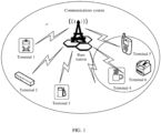
- FIG. 1 shows an architecture of a communications system to which an implementation of this application is applicable.
- the communications system includes an access network device and a plurality of terminal devices (for example, a terminal 1 to a terminal 6 in FIG. 1 ) that communicate with the access network device.
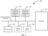
- FIG. 2 is a schematic structural diagram of hardware of a communications device according to an implementation of this application.
- the communications device 200 includes at least one processor 201, a communications line 202, a memory 203, and at least one transceiver 204.
- the communications line 202 may include a path for transmitting information between the foregoing components.
- the transceiver 204 is configured to communicate with another device.
- the transceiver may be an independently disposed transmitter, and the transmitter may be configured to send information to another device.
- the transceiver may be an independently disposed receiver, and is configured to receive information from another device.
- the transceiver may be a component integrating functions of sending and receiving information.
- a specific implementation of the transceiver is not limited in this implementation of this application.
- the memory 203 may be a read-only memory (read-only memory, ROM) or another type of static storage device that can store static information and instructions, or a random access memory (random access memory, RAM) or another type of dynamic storage device that can store information and instructions, or may be an electrically erasable programmable read-only memory (electrically erasable programmable read-only memory, EEPROM), a compact disc read-only memory (compact disc read-only memory, CD-ROM) or another compact disc storage, an optical disc storage (including a compact disc, a laser disc, an optical disc, a digital versatile disc, a Blu-ray optical disc, and the like), a magnetic disk storage medium or another magnetic storage device, or any other medium that can be used to carry or store expected program code in a form of an instruction or a data structure and that can be accessed by a computer.
- the memory 203 is not limited thereto.
- the memory may exist independently, and is connected to the processor through the communications line 202. Alternatively, the memory may
- the memory 203 is configured to store computer-executable instructions for executing the solutions of this application, and the processor 201 controls the execution.
- the processor 201 is configured to execute the computer-executable instructions stored in the memory 203, to implement a resource configuration method provided in the following implementations of this application.
- the computer-executable instructions in this implementation of this application may also be referred to as application program code. This is not specifically limited in implementations of this application.
- the resource indication information may indicate different resource multiplexing manners of the PSCCH and a PSSCH.
- Resource multiplexing manners include time division multiplexing (Time Division Multiplexing, TDM) and frequency division multiplexing (Frequency Division Multiplexing, FDM). The following separately describes the two resource multiplexing manners in a case 1 and a case 2.
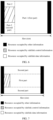
- a quantity of symbols for sending the PSCCH is equal to 12, and a quantity of symbols for sending the PSSCH is also 12.
- a resource for sending the PSCCH and a resource for sending the PSSCH do not overlap in frequency domain, but completely overlap in time domain. That is, FDM is performed between the resource for sending the PSCCH and the resource for sending the PSSCH.
- a length of an SCI format (Format) carried by the PSCCH is determined.
- a bit rate for sending the SCI remains unchanged, a larger quantity of time domain symbols occupied by the PSCCH indicates fewer frequency domain resources occupied by the PSCCH. Therefore, the frequency domain resources occupied by the PSCCH may be determined based on the quantity of time domain symbols occupied by the PSCCH. For example, if a total quantity of time-frequency resources that need to be occupied by the PSCCH is R, and according to FIG. 4 , a time domain resource occupied by the PSCCH is configured to be 12 symbols, the frequency domain resources occupied by the PSCCH is R/12 RBs.
- the transmit end can control a power for sending the PSCCH.
- the transmit end uses a higher transmit power to send the PSCCH to the receive end, so that the PSCCH has higher reliability.
- the receive end receives correct the SCI more possibly, and further, the receive end parses the sidelink data information more possibly, thereby improving reliability of receiving the sidelink data information.
- the time division multiplexing means that frequency division multiplexing is performed between at least a portion of the resource of the sidelink data information and all of the resource of the sidelink control information, and time division multiplexing is performed between at least the portion of the resource of the sidelink data information and all of the resource of the sidelink control information, or time division multiplexing is performed between all of the resource of the sidelink data information and all of the resource of the sidelink control information.
- the quantity of available symbols in the one slot or mini-slot is a quantity of symbols that are used to send the PSCCH and the PSSCH in the one slot or mini-slot.
- frequency division multiplexing is performed between at least the part of the resource of the sidelink data information and all of the resource of the sidelink control information
- time division multiplexing is performed between at least the portion of the resource of the sidelink data information and all of the resource of the sidelink control information.
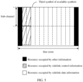
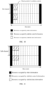
- resources occupied by sidelink data information are divided into two parts.
- a first part (part-1) of resources occupied by the PSSCH and all resources occupied by the PSCCH do not overlap in time domain, that is, time division multiplexing is performed.
- a second part (part-2) of resources occupied by the PSSCH and all resources occupied by the PSCCH are the same in time domain, and do not overlap in frequency domain, that is, frequency division multiplexing is performed.
- a first part (part-1) of resources occupied by the PSSCH and all resources occupied by the PSCCH are the same in frequency domain, and do not overlap in time domain, that is, time division multiplexing is performed.
- a second part (part-2) of resources occupied by the PSSCH and all resources occupied by the PSCCH do not overlap in frequency domain, that is, frequency division multiplexing is performed.
- the resource indication information indicates that time division multiplexing is performed between a resource of the PSSCH and a resource of the PSCCH in the one slot or mini-slot, and a relatively large quantity of frequency domain resources are occupied by the PSSCH in the one slot or mini-slot, a relatively small quantity of symbols are occupied by the PSCCH in the one slot or mini-slot.
- FIG. 9 is used as an example.
- the PSCCH occupies one symbol in one slot. After a time length of the one symbol, the receive end can parse the SCI on the one symbol, and then start to parse the sidelink data information based on the successfully parsed SCI. That is, the receive end may quickly receive and parse the sidelink data information based on the parsed SCI, thereby reducing service latency.
- the quantity of symbols occupied by the PSCCH may be further configured in a mini-slot at a granularity of the mini-slot, to configure resources of the PSCCH and the sidelink data information.
- the resource configuration method in the mini-slot may be applied to an ultra-reliable low-latency communication (Ultra Reliable Low Latency Communications, URLLC) scenario of 5G.
- Ultra Reliable Low Latency Communications, URLLC Ultra-reliable Low Latency Communications, URLLC
- one mini-slot includes seven symbols of a normal CP.
- the resource indication information indicates that the PSCCH occupies two symbols.
- TDM is performed between a resource occupied by the PSCCH and a resource occupied by the PSSCH.
- an example in which TDM is configured between the resource of the PSCCH and the resource of the PSSCH in the one mini-slot is used.
- For a specific method for configuring a resource in the mini-slot refer to the method for configuring a resource in the slot. Details are not described herein again.
- resource configuration can be further performed at a granularity of an extended cyclic prefix (Extended Cyclic Prefix) slot or a mini-slot.
- extended Cyclic Prefix Extended Cyclic Prefix
- For a configuration manner refer to a manner of configuring a resource in a slot or a mini-slot of the normal CP. Details are not described herein again.
- use of 2-bit resource indication information can reduce signaling overheads and meet a requirement of the sidelink communication.
- the resource indication information may alternatively be, for example, 3-bit information. 000 indicates that the PSCCH occupies one symbol in one slot or mini-slot, 001 indicates that the PSCCH occupies two symbols in one slot or mini-slot, and so on.
- the resource indication information may indicate eight different resource configuration cases.
- the resource indication information may alternatively be 1-bit information. For example, 0 indicates that the PSCCH occupies X symbols in one slot or mini-slot. X is a fixed value, and X is an integer greater than or equal to 1 and less than the quantity of available symbols. That is, 2 or 3 indicates a time division multiplexing manner of the PSSCH and the PSCCH, and 1 indicates a frequency division multiplexing manner of the PSSCH and the PSCCH. This implementation has not been claimed as such.
- the terminal obtains the resource indication information in two manners.
- an access network device configures a resource of the terminal.
- the terminal independently determines resources occupied by the PSCCH and the PSSCH. The following separately describes the two manners.
- the terminal may independently select a required resource from a configured resource pool (Resource Pool, RP).
- the resource pool is a set of resources used for sidelink communication.
- the resource pool includes one or more consecutive or non-consecutive resource blocks (Resource block, RB) in frequency domain, or a sidelink resource pool includes one or more consecutive or non-consecutive sub-channels (sub-channel) in frequency domain. Each sub-channel includes one or more consecutive RBs.
- the resource pool includes one or more consecutive or non-consecutive subframes (subframe) in time domain, or the sidelink resource pool includes one or more consecutive or non-consecutive slots and/or mini-slots in time domain.
- the access network device configures, for some terminals that perform a low-latency communication service, a BWP resource 1 used for sidelink communication, and configures, for some other terminals that perform a high-reliability service, a BWP resource 2 used for sidelink communication.
- FIG. 13 an example in which the first terminal and the second terminal use at least some same BWP resources, and the access network device configures the BWP resources is used.
- a specific implementation is S1301. That is, S301 in FIG. 3 may be specifically the following step S1301.
- the access network device sends bandwidth part (BWP) configuration information to the first terminal.
- BWP bandwidth part
- the first terminal receives the BWP configuration information from the access network device.
- FIG. 14 an example in which the first terminal and the second terminal use a same resource pool (RP), and the access network device configures the resource pool is used.
- a specific implementation is S1401. That is, S301 in FIG. 3 may be specifically the following step S1401.
- the scheduling information of the sidelink data information includes but is not limited to an encoding format of the sidelink data information.
- the encoding format is used to indicate a demodulation/decoding format of the sidelink data information, for example, indicate a modulation mode (for example, quadrature phase shift keying (Quadrature Phase Shift Keying, QPSK), 16 quadrature amplitude modulation (16 Quadrature Amplitude Modulation, 16 QAM), or 64 quadrature amplitude modulation (64 Quadrature Amplitude Modulation, 64 QAM)) of the sidelink data information, or indicate at least one of a bit rate of channel coding (for example, a 1/3 bit rate or a 3/4 bit rate), a time-frequency resource used by the PSCCH, reservation information of a PSCCH resource, an indication indicating whether retransmission is performed, a source address of the terminal, a destination address (including a group address) of the terminal, hybrid automatic repeat request (Hybrid Automatic Repeat reQuest, HARQ)
- the first terminal determines, based on the resource indication information, to send the sidelink control information on the first symbol and the second symbol in one slot.
- the sidelink control information may indicate that the modulation mode of the sidelink data information sent by the first terminal is QPSK, and a bit rate of the sidelink data information is the 1/3 bit rate.
- the first terminal sends the sidelink control information on the determined symbol for sending the sidelink control information.
- the first terminal and the second terminal use a same resource pool. Because the first terminal and the second terminal have the same resource indication information, when the first terminal is used as the transmit end of the sidelink communication and the second terminal is used as the receive end of the sidelink communication, the first terminal does not need to notify, by using the PSCCH, the second terminal of the resource indication information used by the first terminal. That is, the SCI in S303 does not include the resource indication information.
- the first terminal sends the sidelink data information to the second terminal on 10 symbols in one slot.
- the modulation mode of the sidelink data information is, for example, QPSK, and the bit rate of the sidelink data information is, for example, the 1/3 bit rate.
- the second terminal determines the symbol for receiving the sidelink control information
- the access network device configures the resource indication information of the second terminal, and then the second terminal determines the symbol for receiving the sidelink control information.
- the sidelink control information occupies two symbols in one slot.
- the second terminal independently determines the resource indication information.
- the first terminal and the second terminal use a same resource pool.
- the resource indication information of the first terminal is the same as the resource indication information of the second terminal.
- the first terminal sends the sidelink data information on the first symbol and the second symbol in the one slot, and correspondingly, the second terminal receives the sidelink data information from the first terminal on the first symbol and the second symbol in the one slot.
- the second terminal receives the sidelink data information from the first terminal based on the scheduling information.
- the first terminal sends the sidelink data information on the 10 symbols in the one slot, and correspondingly, the second terminal receives the sidelink data information from the first terminal on the 10 symbols in the one slot, and receives the sidelink data information by using the 1/3 bit rate.
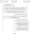
- An implementation of this application further provides a resource configuration method. Referring to FIG. 15 , the method includes the following steps.
- a first terminal obtains resource indication information.
- the resource indication information is used to indicate a quantity of symbols occupied by a PSCCH in one slot (slot) or mini-slot (mini-slot).
- the terminal obtains the resource indication information in two manners.
- an access network device configures a resource of the terminal.
- the terminal independently determines resources occupied by the PSCCH and a PSSCH. The following separately describes the two manners.
- Manner 1 The terminal independently determines the resource indication information. To be specific, the terminal independently determines the quantity of symbols occupied by the PSCCH in one slot or mini-slot. In other words, the terminal obtains the resource indication information based on a higher-layer configuration.
- the terminal may independently select a required resource from a configured resource pool (RP) based on a service requirement.
- RP resource pool
- the configured resource pool includes 20 RBs in frequency domain and 20 slots in time domain.
- the terminal When the terminal currently performs a low-latency service, the terminal independently determines that the PSCCH occupies a relatively small quantity of symbols in the one slot, to meet a requirement of the low-latency service. For another example, if the terminal currently performs a service that requires high reliability, the terminal independently determines that the PSSCH occupies all available symbols in the one slot. That is, FDM is performed between the PSCCH and the PSSCH.
- the access network device configures a resource for a single terminal or a terminal group.
- the access network device configures different resources for different terminals based on service requirements of the different terminals.
- the access network device configures resources for the first terminal and a second terminal. That the access network device configures the different resources for the different terminals may be specifically implemented by S1601, that is, S1501 in FIG. 15 may be specifically S1601.
- the access network device sends first signaling to the first terminal.
- the first terminal receives the first signaling from the access network device.
- the first signaling includes the resource indication information, and the first signaling includes at least one of a system information block (System Information Block, SIB), cell-specific (cell-specific) radio resource control (radio resource control, RRC) signaling, terminal-specific (UE-specific) RRC signaling, terminal-group common signaling (UE-group common signaling), and downlink control information (Downlink Control Information, DCI).
- SIB System Information Block
- RRC radio resource control
- UE-specific terminal-specific (UE-specific) RRC signaling
- UE-group common signaling terminal-group common signaling
- DCI Downlink Control Information
- the access network device may alternatively send the first signaling to the second terminal.
- the second terminal receives the first signaling from the access network device. Therefore, the resource indication information is notified to the second terminal by using the first signaling.
- the first terminal determines, based on the resource indication information, a symbol for sending sidelink control information, where the sidelink control information is used to indicate to send scheduling information of sidelink data information.
- a process of S1502 is the same as that of S302. For details, refer to related descriptions of S302.
- the first terminal sends the sidelink control information on the determined symbol for sending the sidelink control information.
- the first terminal sends the sidelink data information to the second terminal based on the scheduling information.
- the sidelink control information is used to indicate the first terminal to send the scheduling information of the sidelink data information and the symbol for sending the sidelink control information.
- each functional unit may be obtained through division based on a corresponding function, or two or more functions may be integrated into one processing unit.
- the integrated unit may be implemented in a form of hardware, or may be implemented in a form of a software functional unit. It should be noted that in the implementations of this application, division into the units is an example and is merely logical function division, and may be other division during actual implementation.
- the processing unit 1702 may be configured to support the first terminal in performing S301 and S302 in FIG. 3 , and S1502 in FIG. 15 , and/or another process used for the solutions described in this specification.
- the communications unit 1703 is configured to support communication between the first terminal and the another network element (for example, the foregoing first terminal), for example, support the first terminal in performing S302 in FIG. 3 and S1401 in FIG. 14 .
- the sending unit is configured to support the first terminal in sending information to the another network element.
- the sending unit is configured to support the first terminal in performing S302 in FIG.
- the receiving unit is configured to support the first terminal in receiving information from the another network element.
- the receiving unit is configured to support the first terminal in performing S1401 in FIG. 14 , and/or another process used for the solutions described in this specification.
- the processing unit 1702 may be configured to support the second terminal in performing S303 in FIG. 3 , and/or another process used for the solutions described in this specification.
- the communications unit 1703 is configured to support communication between the second terminal and the another network element (for example, the first terminal), for example, support the second terminal in performing S1502 in FIG. 15 .
- the sending unit may be configured to support the second terminal in sending information to the first terminal, or support the second terminal in sending information to the access network device.
- the receiving unit may be configured to support the second terminal in performing S1502 in FIG. 15 , and/or another process used for the solutions described in this specification.
- the processing unit 1702 may be configured to support the access network device in determining a configuration resource to be allocated to the first terminal or the second terminal, and/or another process used for the solutions described in this specification.
- the communications unit 1703 is configured to support communication between the access network device and the another network element (for example, the foregoing first terminal), for example, support the access network device in performing S1401 in FIG. 14 .
- the sending unit may be configured to support the access network device in performing S1601 in FIG. 16 , and/or another process used for the solutions described in this specification.
- the receiving unit may be configured to support the access network device in receiving information from the first terminal or the second terminal.
- the processing unit 1702 may be a controller, or the processor 201 or the processor 207 shown in FIG. 2 , for example, a central processing unit (Central Processing Unit, CPU), a general-purpose processor, a digital signal processing (Digital Signal Processing, DSP), an application-specific integrated circuit (Application Specific Integrated Circuit, ASIC), a field programmable gate array (Field-Programmable Gate Array, FPGA) or another programmable logic device, a transistor logic device, a hardware component, or any combination thereof.
- the processing unit 1702 may implement or execute various example logical blocks, modules, and circuits described with reference to content disclosed in this application.
- the processor may be a combination of processors implementing a computing function, for example, a combination of one or more microprocessors, or a combination of a DSP and a microprocessor.
- the communications unit 1703 may be the transceiver 204 shown in FIG. 2 , or may be a transceiver circuit or the like.
- the storage unit 1701 may be the memory 203 shown in FIG. 2 .
- the computer program product includes one or more computer instructions.
- the computer may be a general-purpose computer, a dedicated computer, a computer network, or another programmable apparatus.
- the computer instructions may be stored in a computer-readable storage medium or may be transmitted from one computer-readable storage medium to another computer-readable storage medium.
- the computer instructions may be transmitted from one website, computer, server, or data center to another web site, computer, server, or data center in a wired (for example, a coaxial cable, an optical fiber, or a digital subscriber line (Digital Subscriber Line, DSL)) or wireless (for example, infrared, radio, or microwave) manner.
- the computer-readable storage medium may be any usable medium accessible by the computer, or a data storage device, such as a server or a data center, integrating one or more usable media.
- the usable medium may be a magnetic medium (for example, a floppy disk, a hard disk, or a magnetic tape), an optical medium (for example, a digital video disc (Digital Video Disc, DVD)), a semiconductor medium (for example, a solid-state drive (Solid State Disk, SSD)), or the like.
- a magnetic medium for example, a floppy disk, a hard disk, or a magnetic tape
- an optical medium for example, a digital video disc (Digital Video Disc, DVD)
- a semiconductor medium for example, a solid-state drive (Solid State Disk, SSD)
- the disclosed system, apparatus, and method may be implemented in other manners.
- the described apparatus implementation is merely an example.
- division into units is merely logical function division and may be other division during actual implementation.
- a plurality of units or components may be combined or integrated into another system, or some features may be ignored or not performed.
- the displayed or discussed mutual couplings or direct couplings or communication connections may be implemented through some interfaces.
- the indirect couplings or communication connections between the apparatuses or units may be implemented in electrical or other forms.
Landscapes
- Engineering & Computer Science (AREA)
- Signal Processing (AREA)
- Computer Networks & Wireless Communication (AREA)
- Mobile Radio Communication Systems (AREA)
Claims (9)
- Ressourcenkonfigurationsverfahren, umfassend:Erlangen (S301) von Ressourcenanzeigeinformationen durch ein erstes Endgerät, wobei die Ressourcenanzeigeinformationen verwendet werden, um ein Symbol oder eine Anzahl von Symbolen anzuzeigen, die durch Sidelink-Steuerinformationen in einem Slot oder Minislot belegt sind;Bestimmen (S302) des Symbols zum Senden der Sidelink-Steuerinformationen durch das erste Endgerät auf Grundlage der Ressourcenanzeigeinformationen, wobei die Sidelink-Steuerinformationen verwendet werden, um anzuzeigen, dass Planungsinformationen von Sidelink-Dateninformationen gesendet werden sollen;Senden (S303) der Sidelink-Steuerinformationen durch das erste Endgerät auf dem bestimmten Symbol zum Senden der Sidelink-Steuerinformationen; undSenden (S304) der Sidelink-Dateninformationen durch das erste Endgerät an ein zweites Endgerät auf der Grundlage der Planungsinformationen;wobei, wenn die Menge der von den Sidelink-Steuerinformationen in dem einen Slot oder Minislot belegten Symbole gleich einer Menge der verfügbaren Symbole in dem einen Slot oder Minislot ist, Frequenzmultiplexen zwischen einer Ressource der Sidelink-Steuerinformationen und einer Ressource der Sidelink-Dateninformationen durchgeführt wird; unddie Menge der verfügbaren Symbole in dem einen Slot oder Minislot eine Menge von Symbolen ist, die zum Senden der Sidelink-Steuerinformationen und der Sidelink-Dateninformationen in dem einen Slot oder Minislot verwendet wird; dadurch gekennzeichnet, dass die Sidelink-Steuerinformationen im Verhältnis zu den Sidelink-Dateninformationen mit einer höheren Leistung übertragen werden.
- Ressourcenkonfigurationsverfahren nach Anspruch 1, wobei das Erlangen von Ressourcenanzeigeinformationen durch ein erstes Endgerät Folgendes umfasst:Empfangen von Bandbreitenteil-BWP-Konfigurationsinformationen von einer Zugangsnetzwerkvorrichtung durch das erste Endgerät, wobei die BWP-Konfigurationsinformationen die Ressourcenanzeigeinformationen umfassen und die Ressourcenanzeigeinformationen des ersten Endgeräts dieselben wie die Ressourcenanzeigeinformationen des zweiten Endgeräts sind; oderdas Erlangen von Ressourcenanzeigeinformationen durch ein erstes Endgerät Folgendes umfasst: Empfangen von Ressourcenpool-RP-Konfigurationsinformationen durch das erste Endgerät von einer Zugangsnetzwerkvorrichtung, wobei die RP-Konfigurationsinformationen die Ressourcenanzeigeinformationen umfassen und die Ressourcenanzeigeinformationen des ersten Endgeräts dieselben wie die Ressourcenanzeigeinformationen des zweiten Endgeräts sind.
- Ressourcenkonfigurationsverfahren nach Anspruch 1, wobei das Erlangen von Ressourcenanzeigeinformationen durch ein erstes Endgerät Folgendes umfasst: unabhängiges Bestimmen der Ressourcenanzeigeinformationen durch das erste Endgerät.
- Ressourcenkonfigurationsverfahren nach Anspruch 1, wobei das erlangen von Ressourcenanzeigeinformationen durch ein erstes Endgerät Folgendes umfasst:
Empfangen einer ersten Signalisierung von einer Zugangsnetzwerkvorrichtung durch das erste Endgerät, wobei die erste Signalisierung die Ressourcenanzeigeinformationen umfasst und die erste Signalisierung mindestens eines der folgenden Elemente umfasst: einen Systeminformationsblock SIB, eine zellenspezifische Funkressourcensteuerungs-RRC-Signalisierung, eine Endgeräte-spezifische RRC-Signalisierung, eine Endgerätegruppenübergreifende UE-Gruppen-Signalisierung und eine Downlink-Steuerungssignalisierung DCI. - Ressourcenkonfigurationsverfahren nach Anspruch 1, wobei die Sidelink-Steuerinformationen außerdem verwendet werden, um das Symbol zum Senden der Sidelink-Steuerinformationen anzugeben.
- Ressourcenkonfigurationsverfahren, umfassend:Erlangen von Ressourcenanzeigeinformationen durch ein zweites Endgerät, wobei die Ressourcenanzeigeinformationen verwendet werden, um ein Symbol oder eine Anzahl von Symbolen anzuzeigen, die durch Sidelink-Steuerinformationen in einem Slot oder Minislot belegt sind;Bestimmen des Symbols zum Enpfangen der Sidelink-Steuerinformationen durch das zweite Endgerät auf Grundlage der Ressourcenanzeigeinformationen, wobei die Sidelink-Steuerinformationen verwendet werden, um anzuzeigen, dass Planungsinformationen von Sidelink-Dateninformationen empfangen werden sollen;Empfangen (S305) der Sidelink-Steuerinformationen von einem ersten Endgerät durch das zweite Endgerät auf dem bestimmten Symbol zum Empfangen der Sidelink-Steuerinformationen, wobei die Sidelink-Steuerinformationen verwendet werden, um dem ersten Endgerät anzugeben, dass die Planungsinformationen der Sidelink-Dateninformationen gesendet werden sollen; undEmpfangen (S306) der Sidelink-Dateninformationen durch das zweite Endgerät von dem ersten Endgerät auf der Grundlage der Planungsinformationen;wobei, wenn die Menge der von den Sidelink-Steuerinformationen in dem einen Slot oder Minislot belegten Symbole gleich einer Menge der verfügbaren Symbole in dem einen Slot oder Minislot ist, Frequenzmultiplexen zwischen einer Ressource der Sidelink-Steuerinformationen und einer Ressource der Sidelink-Dateninformationen durchgeführt wird; unddie Menge der verfügbaren Symbole in dem einen Slot oder Minislot eine Menge von Symbolen ist, die zum Senden der Sidelink-Steuerinformationen und der Sidelink-Dateninformationen in dem einen Slot oder Minislot verwendet wird; dadurch gekennzeichnet, dass die Sidelink-Steuerinformationen im Verhältnis zu den Sidelink-Dateninformationen mit einer höheren Leistung empfangen werden.
- Ressourcenkonfigurationsverfahren nach Anspruch 6, wobei:das Erlangen von Ressourcenanzeigeinformationen durch ein zweites Endgerät Folgendes umfasst: Empfangen von Bandbreitenteil-BWP-Konfigurationsinformationen durch das zweites Endgerät von einer Zugangsnetzwerkvorrichtung, wobei die BWP-Konfigurationsinformationen die Ressourcenanzeigeinformationen umfassen und Ressourcenanzeigeinformationen des ersten Endgeräts dieselben wie die Ressourcenanzeigeinformationen des zweiten Endgeräts sind; oderdas Erlangen von Ressourcenanzeigeinformationen durch ein zweites Endgerät Folgendes umfasst: Empfangen von Ressourcenpool-RP-Konfigurationsinformationen durch das zweite Endgerät von einer Zugangsnetzwerkvorrichtung, wobei die Ressourcenanzeigeinformationen des ersten Endgeräts dieselben wie die Ressourcenanzeigeinformationen des zweiten Endgeräts sind.
- Ressourcenkonfigurationsverfahren nach Anspruch 6, wobei:
das Erlangen von Ressourcenanzeigeinformationen durch ein zweites Endgerät Folgendes umfasst: Empfangen der Sidelink-Steuerinformationen vom ersten Endgerät durch das zweite Endgerät. - Ressourcenkonfigurationsvorrichtung, die zum Ausführen des Verfahrens nach einem der Ansprüche 1 bis 8 konfiguriert ist.
Applications Claiming Priority (2)
| Application Number | Priority Date | Filing Date | Title |
|---|---|---|---|
| CN201811305005.XA CN111148240B (zh) | 2018-11-02 | 2018-11-02 | 资源配置方法及装置 |
| PCT/CN2019/115445 WO2020088688A1 (zh) | 2018-11-02 | 2019-11-04 | 资源配置方法及装置 |
Publications (3)
| Publication Number | Publication Date |
|---|---|
| EP3863347A1 EP3863347A1 (de) | 2021-08-11 |
| EP3863347A4 EP3863347A4 (de) | 2021-12-29 |
| EP3863347B1 true EP3863347B1 (de) | 2025-04-09 |
Family
ID=70464598
Family Applications (1)
| Application Number | Title | Priority Date | Filing Date |
|---|---|---|---|
| EP19878021.5A Active EP3863347B1 (de) | 2018-11-02 | 2019-11-04 | Ressourcenkonfigurationsverfahren und -vorrichtung |
Country Status (4)
| Country | Link |
|---|---|
| US (1) | US20210250159A1 (de) |
| EP (1) | EP3863347B1 (de) |
| CN (1) | CN111148240B (de) |
| WO (1) | WO2020088688A1 (de) |
Families Citing this family (17)
| Publication number | Priority date | Publication date | Assignee | Title |
|---|---|---|---|---|
| US12317228B2 (en) * | 2018-11-15 | 2025-05-27 | Beijing Xiaomi Mobile Software Co., Ltd. | Method and device for transmitting control information and data |
| EP4407919A3 (de) * | 2019-01-11 | 2024-10-23 | Guangdong Oppo Mobile Telecommunications Corp., Ltd. | Sidelink-kommunikationsverfahren, endgerätevorrichtung und netzwerkvorrichtung |
| US20200280981A1 (en) | 2019-02-28 | 2020-09-03 | Samsung Electronics Co., Ltd. | Method and apparatus for managing resource pool in wireless communication system |
| CN113873547A (zh) * | 2020-06-30 | 2021-12-31 | 华为技术有限公司 | 资源配置方法及装置 |
| US11445529B2 (en) * | 2020-08-05 | 2022-09-13 | Qualcomm Incorporated | Techniques for relaying in sidelink communications |
| EP4274333B1 (de) | 2021-01-04 | 2025-04-02 | Guangdong Oppo Mobile Telecommunications Corp., Ltd. | Ressourcenbestimmungsverfahren, -vorrichtung und -vorrichtung sowie speichermedium, chip und programmprodukt |
| CN112512124B (zh) * | 2021-02-03 | 2021-07-09 | 之江实验室 | 一种确定侧行链路传输资源的方法 |
| WO2022222079A1 (zh) * | 2021-04-21 | 2022-10-27 | Oppo广东移动通信有限公司 | 资源配置方法、设备及存储介质 |
| WO2023279403A1 (zh) * | 2021-07-09 | 2023-01-12 | Oppo广东移动通信有限公司 | 无线通信方法、终端设备和网络设备 |
| CN117158085A (zh) * | 2021-07-12 | 2023-12-01 | Oppo广东移动通信有限公司 | 传输资源的请求方法、装置、设备及存储介质 |
| CN117242851A (zh) * | 2021-07-30 | 2023-12-15 | Oppo广东移动通信有限公司 | 无线通信方法、第一设备和第二设备 |
| US11805522B2 (en) * | 2021-08-20 | 2023-10-31 | Qualcomm Incorporated | Sidelink feedback techniques in sidelink wireless communications |
| WO2023039783A1 (en) * | 2021-09-16 | 2023-03-23 | Qualcomm Incorporated | Decoupled mini-slot sidelink control information (sci) for scheduling and resource reservation |
| US20230100366A1 (en) * | 2021-09-24 | 2023-03-30 | Qualcomm Incorporated | Signaling details of network coded transmissions |
| US12207259B2 (en) * | 2022-01-04 | 2025-01-21 | Qualcomm Incorporated | Sidelink mode 1 mini-slot |
| WO2024138757A1 (zh) * | 2022-12-30 | 2024-07-04 | 北京小米移动软件有限公司 | 数据传输方法和装置 |
| WO2025137877A1 (zh) * | 2023-12-26 | 2025-07-03 | Oppo广东移动通信有限公司 | 传输资源的使用方法、装置、设备及存储介质 |
Family Cites Families (9)
| Publication number | Priority date | Publication date | Assignee | Title |
|---|---|---|---|---|
| CN105451211B (zh) * | 2014-09-25 | 2019-12-27 | 中兴通讯股份有限公司 | 用于设备到设备通信的方法及装置 |
| WO2016119241A1 (zh) * | 2015-01-30 | 2016-08-04 | 华为技术有限公司 | 一种d2d通信的数据传输方法和终端 |
| WO2017038509A1 (ja) * | 2015-09-01 | 2017-03-09 | 株式会社Nttドコモ | ユーザ装置及び通信方法 |
| US10123285B2 (en) * | 2016-10-12 | 2018-11-06 | Lg Electronics Inc. | Method for reducing transmission power and vehicle-to-everything (V2X) communication device thereof |
| CN108512576A (zh) * | 2017-02-28 | 2018-09-07 | 华为技术有限公司 | 一种实现用户设备协作的方法及装置 |
| EP3628133B1 (de) * | 2017-05-04 | 2024-01-10 | Koninklijke Philips N.V. | Intragruppe kommunikation |
| EP3821658A1 (de) * | 2018-08-09 | 2021-05-19 | Convida Wireless, Llc | Ressourcenverwaltung für 5g ev2x |
| CN110932827B (zh) * | 2018-09-19 | 2021-11-19 | 华为技术有限公司 | 一种侧行信息的传输方法、通信设备和网络设备 |
| CN210813050U (zh) | 2019-07-19 | 2020-06-23 | 中国人民解放军联勤保障部队第九0四医院 | 便携式战地输液架 |
-
2018
- 2018-11-02 CN CN201811305005.XA patent/CN111148240B/zh active Active
-
2019
- 2019-11-04 EP EP19878021.5A patent/EP3863347B1/de active Active
- 2019-11-04 WO PCT/CN2019/115445 patent/WO2020088688A1/zh not_active Ceased
-
2021
- 2021-04-28 US US17/242,538 patent/US20210250159A1/en not_active Abandoned
Also Published As
| Publication number | Publication date |
|---|---|
| CN111148240A (zh) | 2020-05-12 |
| EP3863347A4 (de) | 2021-12-29 |
| US20210250159A1 (en) | 2021-08-12 |
| CN111148240B (zh) | 2022-04-12 |
| WO2020088688A1 (zh) | 2020-05-07 |
| EP3863347A1 (de) | 2021-08-11 |
Similar Documents
| Publication | Publication Date | Title |
|---|---|---|
| EP3863347B1 (de) | Ressourcenkonfigurationsverfahren und -vorrichtung | |
| US12335049B2 (en) | Method and apparatus for using HARQ in wireless communications | |
| US20250038932A1 (en) | Method for performing harq feedback procedure | |
| US12237927B2 (en) | Method and apparatus for performing HARQ operation | |
| US12526807B2 (en) | Systems and methods related to sub-slot physical uplink control channel (PUCCH) repetitions | |
| EP3634056B1 (de) | Signalübertragungsverfahren, zugehörige vorrichtung und system | |
| CN111148242B (zh) | 信息传输方法及装置 | |
| US10645680B2 (en) | Methods and devices for performing proximity discovery | |
| US11317425B2 (en) | Data transmission method, related device, and system | |
| WO2018210243A1 (zh) | 一种通信方法和装置 | |
| JP2020523902A (ja) | 通信方法、ネットワークデバイス、およびユーザ機器 | |
| CN116368884A (zh) | 利用朝向多个trp的时隙内重复的pucch增强的系统和方法 | |
| CN112314034B (zh) | 信息发送和接收方法以及装置 | |
| WO2017113077A1 (zh) | 一种上行紧急业务传输方法、基站、用户设备及系统 | |
| JP2018537907A (ja) | スケジューリング情報送信方法および装置 | |
| EP3589042B1 (de) | Verfahren und vorrichtung zum senden von informationen und verfahren und vorrichtung zum empfangen von informationen | |
| WO2022226988A1 (en) | Method and apparatus for pucch transmission | |
| WO2024130651A1 (zh) | 侧行控制信息的发送方法、装置、设备及介质 | |
| US20250344215A1 (en) | Systems and methods related to sub-slot physical uplink control channel (pucch) repetitions | |
| CN113543324B (zh) | 一种目标信息发送方法、接收方法和装置 | |
| WO2018014297A1 (zh) | 信息传输装置、方法以及无线通信系统 | |
| WO2025033024A1 (ja) | 端末、及び、通信方法 | |
| CN112399622A (zh) | 一种控制信息的发送、接收方法和通信装置 |
Legal Events
| Date | Code | Title | Description |
|---|---|---|---|
| STAA | Information on the status of an ep patent application or granted ep patent |
Free format text: STATUS: THE INTERNATIONAL PUBLICATION HAS BEEN MADE |
|
| PUAI | Public reference made under article 153(3) epc to a published international application that has entered the european phase |
Free format text: ORIGINAL CODE: 0009012 |
|
| STAA | Information on the status of an ep patent application or granted ep patent |
Free format text: STATUS: REQUEST FOR EXAMINATION WAS MADE |
|
| 17P | Request for examination filed |
Effective date: 20210504 |
|
| AK | Designated contracting states |
Kind code of ref document: A1 Designated state(s): AL AT BE BG CH CY CZ DE DK EE ES FI FR GB GR HR HU IE IS IT LI LT LU LV MC MK MT NL NO PL PT RO RS SE SI SK SM TR |
|
| A4 | Supplementary search report drawn up and despatched |
Effective date: 20211130 |
|
| RIC1 | Information provided on ipc code assigned before grant |
Ipc: H04W 76/14 20180101ALN20211124BHEP Ipc: H04L 5/00 20060101ALI20211124BHEP Ipc: H04W 72/04 20090101AFI20211124BHEP |
|
| DAV | Request for validation of the european patent (deleted) | ||
| DAX | Request for extension of the european patent (deleted) | ||
| STAA | Information on the status of an ep patent application or granted ep patent |
Free format text: STATUS: EXAMINATION IS IN PROGRESS |
|
| 17Q | First examination report despatched |
Effective date: 20221125 |
|
| REG | Reference to a national code |
Ref legal event code: R079 Ipc: H04L0005000000 Ref country code: DE Ref legal event code: R079 Ref document number: 602019068548 Country of ref document: DE Free format text: PREVIOUS MAIN CLASS: H04W0072040000 Ipc: H04L0005000000 |
|
| GRAP | Despatch of communication of intention to grant a patent |
Free format text: ORIGINAL CODE: EPIDOSNIGR1 |
|
| STAA | Information on the status of an ep patent application or granted ep patent |
Free format text: STATUS: GRANT OF PATENT IS INTENDED |
|
| RIC1 | Information provided on ipc code assigned before grant |
Ipc: H04W 76/14 20180101ALN20241031BHEP Ipc: H04W 72/0453 20230101ALN20241031BHEP Ipc: H04W 72/0446 20230101ALN20241031BHEP Ipc: H04W 72/20 20230101ALI20241031BHEP Ipc: H04L 5/00 20060101AFI20241031BHEP |
|
| INTG | Intention to grant announced |
Effective date: 20241119 |
|
| GRAS | Grant fee paid |
Free format text: ORIGINAL CODE: EPIDOSNIGR3 |
|
| GRAA | (expected) grant |
Free format text: ORIGINAL CODE: 0009210 |
|
| STAA | Information on the status of an ep patent application or granted ep patent |
Free format text: STATUS: THE PATENT HAS BEEN GRANTED |
|
| AK | Designated contracting states |
Kind code of ref document: B1 Designated state(s): AL AT BE BG CH CY CZ DE DK EE ES FI FR GB GR HR HU IE IS IT LI LT LU LV MC MK MT NL NO PL PT RO RS SE SI SK SM TR |
|
| REG | Reference to a national code |
Ref country code: GB Ref legal event code: FG4D |
|
| REG | Reference to a national code |
Ref country code: CH Ref legal event code: EP |
|
| REG | Reference to a national code |
Ref country code: DE Ref legal event code: R096 Ref document number: 602019068548 Country of ref document: DE |
|
| REG | Reference to a national code |
Ref country code: IE Ref legal event code: FG4D |
|
| REG | Reference to a national code |
Ref country code: NL Ref legal event code: MP Effective date: 20250409 |
|
| PG25 | Lapsed in a contracting state [announced via postgrant information from national office to epo] |
Ref country code: NL Free format text: LAPSE BECAUSE OF FAILURE TO SUBMIT A TRANSLATION OF THE DESCRIPTION OR TO PAY THE FEE WITHIN THE PRESCRIBED TIME-LIMIT Effective date: 20250409 |
|
| REG | Reference to a national code |
Ref country code: AT Ref legal event code: MK05 Ref document number: 1784553 Country of ref document: AT Kind code of ref document: T Effective date: 20250409 |
|
| PG25 | Lapsed in a contracting state [announced via postgrant information from national office to epo] |
Ref country code: PT Free format text: LAPSE BECAUSE OF FAILURE TO SUBMIT A TRANSLATION OF THE DESCRIPTION OR TO PAY THE FEE WITHIN THE PRESCRIBED TIME-LIMIT Effective date: 20250811 Ref country code: FI Free format text: LAPSE BECAUSE OF FAILURE TO SUBMIT A TRANSLATION OF THE DESCRIPTION OR TO PAY THE FEE WITHIN THE PRESCRIBED TIME-LIMIT Effective date: 20250409 Ref country code: ES Free format text: LAPSE BECAUSE OF FAILURE TO SUBMIT A TRANSLATION OF THE DESCRIPTION OR TO PAY THE FEE WITHIN THE PRESCRIBED TIME-LIMIT Effective date: 20250409 |
|
| REG | Reference to a national code |
Ref country code: LT Ref legal event code: MG9D |
|
| PG25 | Lapsed in a contracting state [announced via postgrant information from national office to epo] |
Ref country code: NO Free format text: LAPSE BECAUSE OF FAILURE TO SUBMIT A TRANSLATION OF THE DESCRIPTION OR TO PAY THE FEE WITHIN THE PRESCRIBED TIME-LIMIT Effective date: 20250709 Ref country code: GR Free format text: LAPSE BECAUSE OF FAILURE TO SUBMIT A TRANSLATION OF THE DESCRIPTION OR TO PAY THE FEE WITHIN THE PRESCRIBED TIME-LIMIT Effective date: 20250710 |
|
| PG25 | Lapsed in a contracting state [announced via postgrant information from national office to epo] |
Ref country code: PL Free format text: LAPSE BECAUSE OF FAILURE TO SUBMIT A TRANSLATION OF THE DESCRIPTION OR TO PAY THE FEE WITHIN THE PRESCRIBED TIME-LIMIT Effective date: 20250409 |
|
| PG25 | Lapsed in a contracting state [announced via postgrant information from national office to epo] |
Ref country code: BG Free format text: LAPSE BECAUSE OF FAILURE TO SUBMIT A TRANSLATION OF THE DESCRIPTION OR TO PAY THE FEE WITHIN THE PRESCRIBED TIME-LIMIT Effective date: 20250409 |
|
| PG25 | Lapsed in a contracting state [announced via postgrant information from national office to epo] |
Ref country code: HR Free format text: LAPSE BECAUSE OF FAILURE TO SUBMIT A TRANSLATION OF THE DESCRIPTION OR TO PAY THE FEE WITHIN THE PRESCRIBED TIME-LIMIT Effective date: 20250409 |
|
| PG25 | Lapsed in a contracting state [announced via postgrant information from national office to epo] |
Ref country code: AT Free format text: LAPSE BECAUSE OF FAILURE TO SUBMIT A TRANSLATION OF THE DESCRIPTION OR TO PAY THE FEE WITHIN THE PRESCRIBED TIME-LIMIT Effective date: 20250409 |
|
| PG25 | Lapsed in a contracting state [announced via postgrant information from national office to epo] |
Ref country code: RS Free format text: LAPSE BECAUSE OF FAILURE TO SUBMIT A TRANSLATION OF THE DESCRIPTION OR TO PAY THE FEE WITHIN THE PRESCRIBED TIME-LIMIT Effective date: 20250709 |
|
| PG25 | Lapsed in a contracting state [announced via postgrant information from national office to epo] |
Ref country code: IS Free format text: LAPSE BECAUSE OF FAILURE TO SUBMIT A TRANSLATION OF THE DESCRIPTION OR TO PAY THE FEE WITHIN THE PRESCRIBED TIME-LIMIT Effective date: 20250809 |
|
| PG25 | Lapsed in a contracting state [announced via postgrant information from national office to epo] |
Ref country code: LV Free format text: LAPSE BECAUSE OF FAILURE TO SUBMIT A TRANSLATION OF THE DESCRIPTION OR TO PAY THE FEE WITHIN THE PRESCRIBED TIME-LIMIT Effective date: 20250409 |
|
| PGFP | Annual fee paid to national office [announced via postgrant information from national office to epo] |
Ref country code: DE Payment date: 20250930 Year of fee payment: 7 |
|
| REG | Reference to a national code |
Ref country code: DE Ref legal event code: R097 Ref document number: 602019068548 Country of ref document: DE |
|
| PG25 | Lapsed in a contracting state [announced via postgrant information from national office to epo] |
Ref country code: SM Free format text: LAPSE BECAUSE OF FAILURE TO SUBMIT A TRANSLATION OF THE DESCRIPTION OR TO PAY THE FEE WITHIN THE PRESCRIBED TIME-LIMIT Effective date: 20250409 Ref country code: DK Free format text: LAPSE BECAUSE OF FAILURE TO SUBMIT A TRANSLATION OF THE DESCRIPTION OR TO PAY THE FEE WITHIN THE PRESCRIBED TIME-LIMIT Effective date: 20250409 |
|
| PG25 | Lapsed in a contracting state [announced via postgrant information from national office to epo] |
Ref country code: CZ Free format text: LAPSE BECAUSE OF FAILURE TO SUBMIT A TRANSLATION OF THE DESCRIPTION OR TO PAY THE FEE WITHIN THE PRESCRIBED TIME-LIMIT Effective date: 20250409 |
|
| PG25 | Lapsed in a contracting state [announced via postgrant information from national office to epo] |
Ref country code: EE Free format text: LAPSE BECAUSE OF FAILURE TO SUBMIT A TRANSLATION OF THE DESCRIPTION OR TO PAY THE FEE WITHIN THE PRESCRIBED TIME-LIMIT Effective date: 20250409 |
|
| PG25 | Lapsed in a contracting state [announced via postgrant information from national office to epo] |
Ref country code: RO Free format text: LAPSE BECAUSE OF FAILURE TO SUBMIT A TRANSLATION OF THE DESCRIPTION OR TO PAY THE FEE WITHIN THE PRESCRIBED TIME-LIMIT Effective date: 20250409 Ref country code: SK Free format text: LAPSE BECAUSE OF FAILURE TO SUBMIT A TRANSLATION OF THE DESCRIPTION OR TO PAY THE FEE WITHIN THE PRESCRIBED TIME-LIMIT Effective date: 20250409 |
|
| PG25 | Lapsed in a contracting state [announced via postgrant information from national office to epo] |
Ref country code: IT Free format text: LAPSE BECAUSE OF FAILURE TO SUBMIT A TRANSLATION OF THE DESCRIPTION OR TO PAY THE FEE WITHIN THE PRESCRIBED TIME-LIMIT Effective date: 20250409 |
|
| PLBE | No opposition filed within time limit |
Free format text: ORIGINAL CODE: 0009261 |
|
| STAA | Information on the status of an ep patent application or granted ep patent |
Free format text: STATUS: NO OPPOSITION FILED WITHIN TIME LIMIT |
|
| REG | Reference to a national code |
Ref country code: CH Ref legal event code: L10 Free format text: ST27 STATUS EVENT CODE: U-0-0-L10-L00 (AS PROVIDED BY THE NATIONAL OFFICE) Effective date: 20260218 |
|
| 26N | No opposition filed |
Effective date: 20260112 |