EP3862270B1 - Staufach für ein flugzeug sowie flugzeug mit dem staufach - Google Patents
Staufach für ein flugzeug sowie flugzeug mit dem staufach Download PDFInfo
- Publication number
- EP3862270B1 EP3862270B1 EP21155578.4A EP21155578A EP3862270B1 EP 3862270 B1 EP3862270 B1 EP 3862270B1 EP 21155578 A EP21155578 A EP 21155578A EP 3862270 B1 EP3862270 B1 EP 3862270B1
- Authority
- EP
- European Patent Office
- Prior art keywords
- compartment
- swivelling
- actuating device
- storage compartment
- power assistance
- Prior art date
- Legal status (The legal status is an assumption and is not a legal conclusion. Google has not performed a legal analysis and makes no representation as to the accuracy of the status listed.)
- Active
Links
Images


Classifications
-
- B—PERFORMING OPERATIONS; TRANSPORTING
- B64—AIRCRAFT; AVIATION; COSMONAUTICS
- B64D—EQUIPMENT FOR FITTING IN OR TO AIRCRAFT; FLIGHT SUITS; PARACHUTES; ARRANGEMENT OR MOUNTING OF POWER PLANTS OR PROPULSION TRANSMISSIONS IN AIRCRAFT
- B64D11/00—Passenger or crew accommodation; Flight-deck installations not otherwise provided for
- B64D11/003—Stowage devices for passengers' personal luggage
Definitions
- the invention relates to a storage compartment for an aircraft with the features of the preamble of claim 1.
- the invention further relates to an aircraft with the storage compartment.
- Luggage compartments for aircraft are known, which are arranged in an overhead area of a passenger cabin of aircraft and are used to hold items of hand luggage.
- Such luggage compartments usually have a lowerable chute for holding the luggage, which is lowered manually by a user to open it and raised to close it.
- the total weight of the chute is increased, which results in increased effort, particularly when closing the luggage compartments.
- Force support systems are known which can be switched on by the user if necessary in order to apply an additional closing torque to the chute from a force accumulator, so that the force required for closing is reduced.
- the publication EP 3371052 A1 discloses an overhead luggage compartment for an aircraft with an upper luggage compartment element, with a lower luggage compartment element which is movable between a closed and an open position, with a holding device for holding the lower luggage compartment element in its closed position, with a lifting spring for supporting the movement of the lower one Luggage compartment element from the open position to the closed position, and with a retaining device for fixing the lifting spring in the tensioned state in the open position of the lower luggage compartment element, an operating handle for releasing the retaining device in the open position of the lower luggage compartment element being provided.
- the lower luggage compartment element can be moved from the open position towards the closed position, regardless of its loading status, either with the support of the lifting spring or with the lifting spring fixed in the tensioned state.
- An assistance system assigned to the storage compartment can be activated in response to an actuation of a switch assigned to the storage compartment.
- the assistance system can include a biasing system and a switch.
- the biasing system may be configured to generate a force in a direction toward a closed position for the storage compartment.
- a switch may be connected to the biasing system and configured to activate the biasing system when a selected amount of weight is present in the storage compartment. The force towards the closed position for the storage compartment can be generated in response to the activation of the assistance system.
- a power assist device for use in a luggage compartment with a folding tray has a load measuring mechanism, a force support mechanism and an actuation mechanism.
- the load measuring mechanism is transferred from the inactive operating state to the active operating state by the actuation mechanism when the load determined by the load measuring mechanism exceeds a certain threshold value that is greater than a supporting force.
- the actuating mechanism has cooperating locking elements, of which a first element is connected to a first contact point and a second element is connected to a second contact point.
- the locking elements can move relative to one another in such a way that in an inactive operating state one locking element engages frictionally in the cooperating other locking element and releases it in an active operating state.
- the subject of the invention is a storage compartment which is designed and/or suitable for an aircraft, in particular a passenger aircraft.
- the storage compartment is arranged and/or can be arranged in an overhead area of an aircraft cabin, preferably a passenger cabin, of the aircraft.
- the storage compartment is preferably designed as an overhead luggage compartment, also known as a so-called “OHSC” (Overhead Storage Compartment).
- the storage compartment has a storage compartment housing which is designed and/or suitable for attachment to an aircraft structure.
- the storage compartment housing is attached to the aircraft structure in the overhead area within the aircraft cabin.
- the storage compartment housing preferably has one or more mechanical interfaces for attaching the storage compartment housing to the aircraft structure.
- the storage compartment has a swivel compartment which is designed and/or suitable for holding storage items, in particular pieces of luggage.
- the pivoting compartment is designed as a chute, in particular as a so-called “pivot bin”.
- the swivel compartment is mounted in the storage compartment housing so that it can pivot about a swivel axis via a swivel bearing.
- the pivot compartment can be pivoted about the pivot axis in a pivot range between an open position and a closed position.
- the pivot range is to be understood as an angular range of, for example, more than 45 degrees, preferably more than 65 degrees, in particular more than 90 degrees, in order to understand the pivot axis.
- the open position the storage compartment is open so that the stored goods can be loaded and unloaded.
- the closed position the storage compartment is closed or not accessible from the outside.
- the swivel compartment has a power support device.
- the power support device has the particular function of supporting and/or relieving the load on the swivel compartment during a closing process.
- the force support device has a support force unit, wherein the support force unit can be brought either into an active state or a passive state.
- the supporting force unit provides a supporting force acting in the direction of the closed position, which causes force support to the pivoting compartment when the pivoting compartment closes from the open position in the direction of the closed position.
- the supporting force counteracts a load acting on the swivel compartment.
- the passive state it is Support force unit inactive.
- the support force in the passive state the support force is zero, so that there is no force support when manually closing or opening the swivel compartment.
- the supporting force results in a supporting moment acting on the swivel compartment about the swivel axis.
- the supporting force and/or the supporting moment can be constant in the active state.
- the supporting force and/or the supporting moment can also be variable or adjustable.
- the supporting force and/or the supporting moment in the active state can be dependent on the pivoting angle of the pivoting compartment.
- the support force unit has a force storage device which, in the active state of the support force unit, releases work in the form of the support force to the swivel compartment when the swivel compartment moves towards the closed position, and when the swivel compartment moves towards the open position, it releases work by acting on the swivel compartment from the outside Force, for example the weight of the swivel compartment and/or the opening force applied by the user.
- a force storage device which, in the active state of the support force unit, releases work in the form of the support force to the swivel compartment when the swivel compartment moves towards the closed position, and when the swivel compartment moves towards the open position, it releases work by acting on the swivel compartment from the outside Force, for example the weight of the swivel compartment and/or the opening force applied by the user.
- the force support device has an actuation unit with an actuation device which is designed and/or suitable for actuating the support force unit.
- the actuating device When the actuating device is actuated, the support force unit is switched from the passive state to the active state.
- the actuation device is used for manual actuation of the support force unit.
- the user can switch on the support power unit by actuating the actuating device regardless of the loading status of the swivel compartment, so that the closing process of the swivel compartment is implemented either with or without power support.
- actuation of the actuating device is prevented in the closed position of the swivel compartment and is possible in the open position of the swivel compartment.
- the actuating device is covered and/or locked and/or inactive in the closed position of the swivel compartment, so that the actuating device cannot be actuated by the user.
- the actuation device is accessible and/or released and/or active in the open position, so that the actuation device can be actuated by the user.
- the actuation of the actuating device is preferably prevented only in the closed position.
- the operation of the Actuating device only possible in the open position.
- actuation of the actuating device is possible both in the open position and in any intermediate position of the swivel compartment between the open and closed positions.
- the advantage of the invention is, in particular, that by preventing the actuation of the actuation device in the closed position, accidental or improper triggering of the actuation device by the user can be avoided. Damage or malfunction of the power assistance device can thus be prevented and the operational safety of the storage compartment can also be increased.
- the actuating device is arranged in the swivel compartment.
- the actuating device is therefore accessible in the open position via a loading opening defined by the pivoting compartment and/or via the storage space defined by the pivoting compartment.
- the actuating device is covered by the swivel compartment housing.
- a hidden and/or easily accessible arrangement of the actuating device in the open position of the swivel compartment can be achieved.
- the actuating device is arranged laterally on the swivel compartment.
- the actuating device can be arranged either inside or outside the swivel compartment, in particular the storage space. In the closed position, the actuating device is covered by the swivel compartment housing.
- the lateral arrangement of the actuating device makes it easy to operate and/or reach the actuating device in the open position of the swivel compartment.
- the swivel compartment has a loading edge, also known as a "bin lip", on its front.
- the loading edge serves to secure the stored goods in the open position of the swivel compartment and/or as a handle for opening or closing the swivel compartment.
- the loading edge extends, particularly in the longitudinal direction of the aircraft, over the entire width of the swivel compartment.
- the loading edge preferably defines a front edge of the swivel compartment.
- the loading edge can be formed by a web or a bar.
- the actuating device is arranged in the swivel compartment on the loading edge.
- the actuating device can either be arranged and/or fastened on the loading edge or integrated and/or recessed into the loading edge.
- the actuating device is arranged in the open position outside of a visible area and/or covered by the loading edge. It is an idea of the invention to propose an actuation unit which is characterized by a space-saving arrangement of the actuation device.
- the swivel compartment has a side wall which is designed and/or suitable for the lateral delimitation of the storage compartment.
- the actuating device can be arranged outside the swivel compartment on the side wall.
- a gap in particular an air gap, is formed between the side wall and the storage compartment housing, with the actuating device being arranged concealed in the gap in the closed position of the swivel compartment. In the open position, the actuating device is arranged outside the intermediate space and is therefore freely accessible and/or arranged in the visible area.
- the actuating device can be arranged on the side wall within the swivel compartment.
- the actuating device In the closed position of the swivel compartment, the actuating device is arranged concealed in the storage space. In the open position, the actuating device is freely accessible via the loading opening and/or arranged in the visible area.
- An actuating device is therefore proposed which is easy to access and/or operate due to the lateral arrangement and at the same time is easy to assemble.
- the actuation unit has a cable pull which is designed and/or suitable for transmitting an actuation force from the actuation device to the support force unit.
- the actuation device is connected to an actuation mechanism via the cable pull.
- the actuation mechanism has the function of switching the support force unit from the passive state to the active state under the influence of the actuation force.
- the actuation mechanism is designed to convert the actuation force into a mechanical movement.
- the cable pull is particularly preferably designed as a Bowden cable.
- the cable can start from the actuating device on a lower edge of the swivel compartment, in particular the side wall, be moved towards the support force unit.
- An actuation unit is therefore proposed which is characterized by a particularly simple and cost-effective structure.
- the cable pull implements a flexible power transmission, which enables a high degree of design freedom in the arrangement of the actuating device.
- the actuating device has a push button.
- the push button is to be understood as a button which is actuated by pressing and automatically returns to its starting position after being released.
- the push button is preferably loaded via a spring element.
- the support force unit is switched from the passive state to the active state.
- the actuation force is generated as a pressure force and transmitted via the cable to the support force unit, in particular the actuation mechanism. It is therefore an idea of the invention to propose an actuating device which is characterized by a particularly simple operation and at the same time can be implemented cost-effectively.
- the actuating device has a rocker arm.
- a rocker arm is to be understood as meaning a two-sided lever which is rotatably mounted about a pivot point.
- the rocker arm can be designed either as a straight or as a bent lever.
- the push button engages one end of the lever and the cable pull acts on the other lever end of the rocker arm, so that a pressure force generated when the push button is pressed is converted into a tensile force acting on the cable pull as the actuation force.
- the rocker arm and/or the cable pull is firmly connected to the associated lever end.
- the push button is motion-coupled to the cable pull via the rocker arm, so that the rocker arm and the cable pull are automatically returned to their starting position when the push button is released.
- the actuating device has at least or exactly one deflection roller.
- the deflection roller is to be understood as a fixed roller, which is rotatably mounted on an axis of rotation and serves to redirect the actuating force.
- the cable pull is connected to the push button via the deflection roller, so that a pressure force generated when the push button is pressed is deflected into a tensile force acting on the cable pull as the actuation force becomes.
- the deflection roller is preferably used to guide a pull rope of the cable in a non-slip manner, with a rolling movement occurring between the deflection roller and the pull rope when the push button is pressed.
- the cable is deflected by at least approximately 90 degrees, preferably by at least approximately 180 degrees, via the deflection roller.
- the phrase “at least approximately” means angular deviations of, for example, +/- 10 degrees.
- the actuating device has a further deflection roller, with the cable pull being deflected over the two deflection rollers.
- the cable can be deflected by 90 degrees via one deflection pulley and another 90 degrees via the other deflection pulley.
- the actuating device can be locked.
- the actuating device can be switched between a blocking state and a release state, with triggering of the actuating device being prevented and blocked in the blocking state and being possible and enabled in the release state.
- the actuating device can be released or blocked regardless of the position of the swivel compartment.
- the actuation unit has a key element which is designed and/or suitable for unlocking the actuation device.
- the key element is designed to unlock the actuating device by means of touch and/or the key-lock principle.
- the key element can also be designed to unlock the actuating device without contact.
- the key element is preferably designed as a hand-held key element.
- An actuation unit is therefore proposed which is characterized by increased operational safety, with the key element being able to ensure that only an authorized user can trigger the actuation device.
- the key element is designed as a mechanical and/or electrical and/or magnetic key.
- the key element can be designed, for example, as a conventional key, which interacts with a corresponding lock of the actuating device for unlocking.
- the mechanical key can also be designed as a special tool with a special geometry, which interacts with a complementary mating interface of the actuating device for unlocking.
- the key element can be used as a magnetic card key or RFID key be designed, which can be read for unlocking by a reading module of the actuating device.
- the key element can also be designed as a purely magnetic key, which can interact with a corresponding magnetic lock of the actuating device for unlocking. This means that triggering the actuating device is only possible in combination with the corresponding key element, so that the operational safety of the actuating device is significantly increased.
- the key element is used to operate the actuating device, with the support force unit being switched from the passive state to the active state by rotating the key element.
- the key element is preferably designed as a mechanical key.
- the actuating force is generated at the same time.
- the mechanical key is inserted into the lock or the counter interface and then turned in order to unlock and operate the actuating device at the same time.
- the cable is preferably in operative connection with the key element, so that the manual force applied during rotation can be transferred to the cable as the actuating force.
- a lockable actuating device is therefore proposed, which is characterized by a particularly compact and cost-effective design.
- the force support device is designed to be electricity-free and/or purely mechanical with regard to the generation of the support force.
- the power support device is designed to be electricity-free and/or purely mechanical with regard to the switching between active state and passive state.
- the term "electricity-free” is to be understood as meaning that no electrical, electronic, electromechanical or other electricity-based elements are involved. A force support device is therefore proposed which is characterized by a particularly simple and cost-effective structure.
- the support force unit can have a gas pressure spring as the force storage, which is designed and/or suitable for generating the support force.
- the support force unit has a holding part, wherein the gas pressure spring is attached to the holding part, in particular in an articulated manner.
- the holding part is arranged on the storage compartment housing, in particular on a side wall of the storage compartment housing.
- the gas pressure spring has a free gas pressure spring end, wherein the gas pressure spring end can be brought into operative connection with the pivoting compartment in the active state and/or is operatively connected in order to apply the supporting force to the pivoting compartment.
- the end of the gas pressure spring introduces the supporting force into the pivot compartment at an application point in order to generate the supporting torque about the pivot axis.
- the support force unit can have a spiral spring as the force accumulator, which is designed and/or suitable for generating the support force.
- the support force unit has a receiving housing, wherein the spiral spring is received, in particular wound, in the receiving housing.
- the receiving housing is arranged on the storage compartment housing, in particular on the side wall of the storage compartment housing.
- the spiral spring has a free spiral spring end, wherein the spiral spring end can be brought into operative connection with the pivoting compartment in the active state and/or is operatively connected in order to apply the supporting force to the pivoting compartment.
- the spiral spring end introduces the supporting force into the pivot compartment at an application point in order to generate the supporting moment about the pivot axis.
- Another subject of the invention relates to an aircraft with the storage compartment as already described above.
- the aircraft is designed as a passenger aircraft, with the storage compartment being arranged in the overhead area of the passenger cabin and serving to accommodate hand luggage.
- the Figures 1a, b each show, in an axial view with respect to a pivot axis SA, a storage compartment 1, which is used for arrangement in an overhead area of a passenger cabin of an aircraft, in particular a passenger aircraft.
- the storage compartment 1 has a storage compartment housing 2 and a swivel compartment 3 which is pivotally mounted in the storage compartment housing 2 about the pivot axis SA.
- the storage compartment housing 2 can be mounted on an aircraft structure of the aircraft.
- the swivel compartment 3 is designed as a chute and is used to hold storage items, such as hand luggage.
- the swivel compartment 3 is mounted on both sides via a swivel bearing 4 on the storage compartment housing 2, the swivel compartment 3 being pivotable relative to the storage compartment housing 2 via the swivel bearing 4 in a swivel range SB between an open position O and a closed position S.
- the open position O as in Figure 1a shown, the swivel compartment 3 is accessible for inserting or removing the stored items.
- the closed position S as in Figure 1b shown, the swivel compartment 3 is pivoted into the storage compartment housing 2, so that access to the swivel compartment 3 is blocked.
- a power support device 5 is therefore proposed, which is designed to provide purely mechanical power support for the lowerable swivel compartment 3.
- the power support device 5 has a mechanical support force unit 6, which is designed to transmit a support force to the swivel compartment 3 for power support.
- the support force unit 5 can only be arranged on one side. Optionally, however, a further supporting force unit 5 can also be provided on the opposite side.
- the support force unit 6 can be switched between an active state and a passive state.
- the support force unit 6 provides the support force.
- the supporting force results in a supporting moment M about the pivot axis SA, which counteracts a load acting on the pivot compartment 3 in a partial area TB of the pivot area SB, whereby a user's hand force required to close the pivot compartment 3 is reduced.
- the support force unit 6 does not provide any support force, so that the swivel compartment 3 has to be pivoted from the open position O into the closed position S exclusively by hand force.
- the power support device 5 has an actuation unit 7 with an actuation device 8 for actuating the support force unit 6, wherein when the actuation device 8 is actuated, the support force unit 6 is switched from the passive state to the active state.
- the actuating device 8 is in operative connection with the supporting force unit 6 via a cable 9, for example a Bowden cable.
- the swivel compartment 3 has a side wall 10 for the lateral delimitation of the storage compartment 3, the actuating device 8 being mounted laterally outside the swivel compartment 3 on the side wall 10.
- the actuating device 8 is arranged in such a way that the actuating device 8 can be triggered manually by the user in the open position O if necessary and is covered by the storage compartment housing 2 in the closed position S. In the closed position S, the actuating device 8 is arranged between the storage compartment housing 2 and the swivel compartment 3.
- the support force unit 6 can be activated by the actuating device 8 if the user suspects that the load acting on the swivel compartment 3 is too large.
- the user can estimate the weight by briefly lifting the swivel compartment 3.
- the support force unit 6 has a gas pressure spring 11 for generating the support force, which is attached to the storage compartment housing 2 tangentially to the pivot bearing 4 via a holding part 12.
- the holding part 12 is arranged coaxially to the pivot axis SA and can be fixed to the storage compartment housing 2, for example via fastening means.
- the gas pressure spring 11 is connected to the holding part 12 in an articulated, in particular pivotable, manner.
- the support force unit 6 also has a guide part 13 arranged on the side wall 10 of the swivel compartment 3, which serves to guide the gas pressure spring 11 when the swivel compartment 3 moves between the open and closed positions O, S.
- the gas pressure spring 11 has a gas pressure spring end 14, the gas pressure spring end 14 being supported in the active state via the guide part 13 on the swivel compartment 3 in the direction of the locking position S in order to apply the supporting force to the swivel compartment 3.
- the support force unit 6 is switched to the passive state, for which purpose, for example, a damper valve of the gas pressure spring 11 is blocked.
- the gas pressure spring 11 is released, so that the gas pressure spring end 14 performs a stroke to transmit the supporting force and the supporting torque M is transferred to the swivel compartment 3.
- closing the swivel compartment 3 presses the gas pressure spring 11 in the direction of the closed position S against the guide part 13 and thus supports the closing movement of the swivel compartment 3.
- the gas pressure spring 11 transmits the supporting force within the sub-area TB to the swivel compartment 3, the sub-area TB, for example, by a maximum stroke of the gas pressure spring 11 is limited.
- the stroke ends in a range of more than 3 cm and/or less than 10 cm before the closed position, so that when the maximum stroke is reached, no more supporting force is transmitted to the swivel compartment 3.
- a further closing movement into the closed position S thus takes place without force support and exclusively by the user's hand strength in order to implement anti-pinch protection.
- Figure 2a shows in the same representation as Figure 1b the storage compartment 1 in the closed position S of the swivel compartment 3, the support force unit 6 being switched to the passive state.
- the swivel compartment 3 In the passive state, the swivel compartment 3 can be moved from the open position O, as in Figure 1a shown can be moved in the direction of the closed position S without force support.
- the gas pressure spring 11 In order to close an unloaded storage compartment 1, it is not necessary to release the gas pressure spring 11, so that the support force unit 6 remains in the passive state during the closing movement of the pivot compartment 3 and thus no force support is provided by the gas pressure spring 11.
- the swivel compartment 3 is thus guided into the closed position S exclusively by hand, with the gas pressure spring 11 being carried in the guide part 13 about the swivel axis SA without force transmission.
- Figure 2b shows the support force unit 6 from the previous figures in a perspective view.
- a ball 15 is arranged on the gas pressure spring end 14, which in the active state is supported and/or can be supported in a point of contact on the guide part 13 for transmitting the supporting force is.
- the guide part 13 has a support section 16, with the gas pressure spring end 14 in the active state resting positively on the support section 16 via the ball 15.
- the ball 15 is firmly connected to the gas pressure spring end 14, the support section 13 having a ball track on a side facing the ball 15, in which the ball 15 is received and/or guided in a form-fitting manner.
- the ball 15 provides an articulated and/or low-friction support on the guide part 14, whereby the functional reliability of the support force unit 6 can be guaranteed even under high loads.
- FIGS. 3a, b show an alternative embodiment of the power support device 5 as a further exemplary embodiment of the invention.
- the function of the power support device 5 can be found in the previous description, which is why only the relevant differences will be discussed.
- Figure 3a shows the swivel compartment 1 in a perspective view, with the swivel compartment being arranged in the open position O.
- Figure 3b shows the support force unit 6 in an exploded view.
- the supporting force unit 6 has a spiral spring 17 for generating the supporting force, which is accommodated coaxially with the pivot axis S in a receiving housing 18.
- a center point of the spiral spring 17 lies on the pivot axis SA, with the spiral spring 17 being wound around the pivot axis SA in the receiving housing 18.
- the receiving housing 18 is fastened to the storage compartment housing 2, for example via fastening means.
- the receiving housing 18 is designed in two parts, with the spiral spring 17 being captively received axially between a first and a second housing component 18a, b with respect to the pivot axis SA.
- the two housing components 18a, b can, for example, be connected to one another in a detachable manner, for example via a screw connection.
- the second housing component 18b has a bearing section 19 for supporting the pivoting compartment 3, the pivoting compartment 3 in turn having a counter-bearing section 20 for receiving the bearing section 19, as in the Figure 3b shown, has, In an installation situation, the bearing section 19 and the counter-bearing section 20 are pivotally supported on each other to form the pivot bearing 4, so that the pivot compartment 3 is pivotally supported on the receiving housing 18.
- the support force unit 6 also has a plain bearing device 21 to form a Sliding bearing between the bearing section 19 and the counter bearing section 20.
- the plain bearing device 21 is formed, for example, by one or more plain bearing rings, which are arranged in a form-fitting and/or non-positive manner on the bearing section 19 and/or the counter-bearing section 20.
- the actuation unit 7 has a spring-loaded locking lever 22, which locks the spiral spring 17 in the passive state of the support force unit 11 and releases the spiral spring 17 in the active state to transmit the support force.
- the locking lever 22 is designed in the manner of a locking pawl, wherein the locking lever 22 is rotatably mounted about a bolt section 23 arranged on the first housing component 11a.
- the locking lever 22 is connected to the actuating device 8 via the cable 9, with the locking lever 22 being subjected to an actuating force via the cable 9 when the actuating device 8 is triggered, so that the locking lever 22 is pivoted and then automatically returns to its starting position .
- the second housing component 18b has a guide link 24, with a driving contour 20a arranged on the counter bearing section 20 being received in a guided manner in the guide link 24.
- the counter bearing section 20 is designed as a separate component, which is mounted coaxially to the pivot axis SA on the side wall 10 of the pivot compartment 3 via a fastening flange 20b.
- the driving contour 20a is designed as a web formed on the fastening flange 20b, which is aligned in the axial direction with respect to the pivot axis SA.
- the spiral spring 10 has a spiral spring end 25, the spiral spring end 25 resting against the driving contour 20a in the active state of the supporting force unit 6 in the direction of the locking position S in order to transmit the supporting force to the pivoting compartment 3 via the driving contour 20a.
- the locking lever 22 engages with the spiral spring end 25 in such a way that the supporting force is introduced directly into the locking lever 22 and thus into the receiving housing 18.
- the locking lever 22 is pivoted by the user, eg crew or passenger, by triggering the actuating device 8, so that the spiral spring end 25 is released.
- the supporting force is thus introduced into the driving contour 20a via the spiral spring end 25, so that the supporting torque M is transferred to the swivel compartment 3.
- the spiral spring 17 transmits the supporting force within the sub-area TB, as in Figure 1a shown, on the swivel compartment 3, the partial area TB being limited, for example, by a spring stop, not shown, just before the closed position S. In this way, anti-pinch protection is realized, with no supporting force being transmitted to the driving contour 20a in the pivoting area SB between the spring stop and the closed position S and a further closing movement into the closed position S taking place exclusively by the user's hand force.
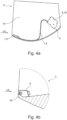
- Figure 4a shows the swivel compartment 3 in a schematic sectional view with an alternative arrangement of the actuating device 8.
- the actuating device 8 is mounted within the swivel compartment 3 on a front side VS on the swivel compartment floor.
- the actuating device 8 can be arranged, for example, laterally or centrally in the swivel compartment 3 in the longitudinal direction of the aircraft. In particular, the actuating device 8 can be triggered by the user from the front or from above.
- FIG 4b shows, in a highly schematic sectional view, a detailed view of the swivel compartment 3 with a further alternative arrangement of the actuating device 8.
- the actuating device 8 is arranged within the swivel compartment 3 on a loading edge 26.
- the loading edge 26 is formed, for example, by a strip arranged on the front VS of the swivel compartment 3, which extends over the entire width of the swivel compartment 3.
- the actuating device 8 is arranged on the loading edge 26 in such a way that the actuating device 8 can be actuated from the rear in the open position O of the swivel compartment 3. The user must therefore reach over the loading edge 26 in order to be able to trigger the actuating device 8.
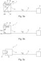
- FIGS 5a, b, c show different versions of the actuating device 8 in a schematic representation, of which only Figure 5c is according to the invention.
- the actuating device 8 each has a push button 27, which switches the support force unit 6 from the passive state to the active state when pressed.
- the push button 27 is loaded by a spring element 28, the pressed push button 27 being automatically pushed back into its starting position by the spring element 28 after being released.
- the actuating device 8 has a rocker arm 29, which is rotatably mounted about a pivot point DP in a housing of the actuating device 8.
- the rocker arm 29 is designed as a two-sided lever, with the push button 27 acting on one lever end 29a and the cable pull 9 acting on the other lever end 29b.
- a pressure force F1 is generated, which results in a rotation of the rocker arm 29 about the pivot point DP.
- the pressure force F1 is converted by the rocker arm 29 into a tensile force F2 acting on the cable pull 9 in order to switch the support force unit 6 from the passive to the active state.
- the actuating device 8 has two deflection rollers 30a, b, which are rotatably mounted in the housing of the actuating device 8.
- the cable pull 9 is guided to the push button 27 via the two deflection rollers 30a, b and is firmly connected to the push button 27.
- the compressive force F1 generated is converted into the tensile force F2, with the tensile force F2 acting on the cable pull 9 being redirected via the two deflection rollers 30a, b.
- the cable pull 9 is deflected by 90 degrees by a deflection roller 30a and by a further 90 degrees by the other deflection roller 30b, so that the cable pull 9 is deflected by a total of 180 degrees.
- the actuating device 8 can be switched between a release state and a blocking state, the actuating device 8 being operable in the release state and blocked in the blocking state.
- the actuation unit 7 has a key element 31 in order to switch the actuation device 8 from the locking state to the release state.
- the key element 31 can be designed as a mechanical key.
- the key element 31 can have, for example, a hexagonal geometry or a star geometry which the key element 31 can be brought into positive engagement with a complementary mating interface 32 of the actuating device 8 in order to unlock the actuating device 8 by rotating the key element 31.
- the tensile force F2 can be applied to the cable pull 9 by rotating the key element, so that the support force unit 6 is actuated.
- the actuating device 8 can also be unlocked, for example, using RFID, fingerprint, inductive near-field coupling or magnetic triggering.
Landscapes
- Engineering & Computer Science (AREA)
- Aviation & Aerospace Engineering (AREA)
- Vehicle Step Arrangements And Article Storage (AREA)
Description
- Die Erfindung betrifft ein Staufach für ein Flugzeug mit den Merkmalen des Oberbegriffs des Anspruchs 1. Ferner betrifft die Erfindung ein Flugzeug mit dem Staufach.
- Es sind Gepäckfächer für Flugzeuge bekannt, welche in einem Überkopfbereich einer Passagierkabine von Flugzeugen angeordnet sind und zur Aufnahme von Handgepäckstücken dienen. Derartige Gepäckfächer weisen in der Regel eine absenkbare Schütte zur Aufnahme der Gepäckstücke auf, welche zum Öffnen händisch durch einen Benutzer abgesenkt und zum Schließen angehoben wird. Beim Beladen der Schütte wird das Gesamtgewicht der Schütte erhöht, was insbesondere beim Schließen der Gepäckfächer einen erhöhten Kraftaufwand zur Folge hat. Es sind Kraftunterstützungssysteme bekannt, welche bei Bedarf durch den Benutzer zugeschaltet werden können, um die Schütte mit einem zusätzlichen Schließmoment aus einem Kraftspeicher zu beaufschlagen, sodass der zum Schließen notwendigen Kraftaufwand reduziert wird.
- Die Druckschrift
EP 3371052 A1 offenbart ein Überkopf-Gepäckfach für ein Flugzeug mit einem oberen Gepäckfachelement, mit einem unteren Gepäckfachelement, welches zwischen einer Schließ- und einer Offenstellung beweglich ist, mit einer Halteeinrichtung zum Halten des unteren Gepäckfachelements in dessen Schließstellung, mit einer Hebefeder zur Unterstützung der Bewegung des unteren Gepäckfachelements aus der Offenstellung in die Schließstellung, und mit einer Rückhalteeinrichtung zur Fixierung der Hebefeder im gespannten Zustand in der Offenstellung des unteren Gepäckfachelementes, wobei ein Betätigungsgriff zur Freigabe der Rückhalteeinrichtung in der Offenstellung des unteren Gepäckfachelementes vorgesehen ist. Das untere Gepäckfachelement ist dabei unabhängig von dessen Beladungszustand, wahlweise mit Unterstützung durch die Hebefeder oder mit im gespannten Zustand fixierter Hebefeder von der Offenstellung in Richtung der Schließstellung beweglich. - Aus der
US 2014 / 0283336 A1 ist ein Verfahren und eine Vorrichtung zum Unterstützen der Bewegung eines Staufaches in eine geschlossene Position bekannt. Ein dem Staufach zugeordnetes Assistenzsystem kann als Reaktion auf eine Betätigung eines dem Staufach zugeordneten Schalters aktiviert werden. Das Assistenzsystem kann ein Vorspannsystem und einen Schalter umfassen. Das Vorspannsystem kann konfiguriert sein, um eine Kraft in einer Richtung zu einer geschlossenen Position für das Staufach zu erzeugen. Ein Schalter kann mit dem Vorspannsystem verbunden und so konfiguriert sein, dass er das Vorspannsystem aktiviert, wenn eine ausgewählte Gewichtsmenge in dem Staufach vorhanden ist. Die Kraft in Richtung der geschlossenen Position für das Staufach kann als Reaktion auf das Aktivieren des Assistenzsystems erzeugt werden. Aus derUS 2014 / 0246968 A1 ist eine Kraftunterstützungsvorrichtung zur Verwendung in einem Gepäckfach mit einer Klappschale bekannt. Diese weist einen Lastmessmechanismus, einen Kraftunterstützungsmechanismus und einen Betätigungsmechanismus auf. Der Lastmessmechanismus wird durch den Betätigungsmechanismus von dem inaktiven Betriebszustand in den aktiven Betriebszustand überführt, wenn die durch den Lastmessmechanismus ermittelte Last einen bestimmten Schwellenwert überschreitet, der größer als eine Unterstützungskraft ist. Der Betätigungsmechanismus weist zusammenwirkende Verriegelungselemente auf, von denen ein erstes Element mit einem ersten Anlagepunkt verbunden ist und ein zweites Element mit einem zweiten Anlagepunkt verbunden ist. Die Verriegelungselemente können sich derart relativ zueinander bewegen, dass in einem inaktiven Betriebszustand das eine Verriegelungselement reibschlüssig in das zusammenwirkende andere Verriegelungselement eingreift und dieses in einem aktiven Betriebszustand freigibt. - Es ist Aufgabe der vorliegenden Erfindung ein Staufach für ein Flugzeug vorzuschlagen, welches sich durch eine verbesserte Bedienbarkeit auszeichnet.
- Die Aufgabe wird durch ein Staufach gemäß Anspruch 1 sowie durch ein Flugzeug gemäß Anspruch 11 gelöst. Bevorzugte oder vorteilhafte Ausführungsformen der Erfindung sowie anderer Erfindungskategorien ergeben sich aus den weiteren Ansprüchen, der nachfolgenden Beschreibung sowie den beigefügten Figuren.
- Gegenstand der Erfindung ist ein Staufach, welches für ein Flugzeug, insbesondere ein Passagierflugzeug, ausgebildet und/oder geeignet ist. Insbesondere ist das Staufach in einem Überkopfbereich einer Flugzeugkabine, vorzugsweise einer Passagierkabine, des Flugzeugs angeordnet und/oder anordenbar. Bevorzugt ist das Staufach als ein Überkopf-Gepäckfach, auch als sogenanntes "OHSC" (Overhead Storage Compartment) bekannt, ausgebildet.
- Das Staufach weist ein Staufachgehäuse auf, welches zur Befestigung an einer Flugzeugstruktur ausgebildet und/oder geeignet ist. Insbesondere ist das Staufachgehäuse innerhalb der Flugzeugkabine in dem Überkopfbereich an der Flugzeugstruktur befestigt. Vorzugsweise weist das Staufachgehäuse eine oder mehrere mechanische Schnittstellen zur Befestigung des Staufachgehäuses an der Flugzeugstruktur auf.
- Das Staufach weist ein Schwenkfach auf, welches zur Aufnahme von Staugut, insbesondere Gepäckstücke, ausgebildet und/oder geeignet ist. Insbesondere ist das Schwenkfach als eine Schütte, im Speziellen als ein sogenannter "Pivot-Bin", ausgebildet. Das Schwenkfach ist in dem Staufachgehäuse über ein Schwenklager um eine Schwenkachse schwenkbar gelagert. Um die Schwenkachse kann das Schwenkfach dabei in einem Schwenkbereich zwischen einer Offenstellung und einer Schließstellung verschwenkt werden. Insbesondere ist der Schwenkbereich als ein Winkelbereich, von beispielsweise mehr als 45 Grad, vorzugsweise mehr als 65 Grad, im Speziellen mehr als 90 Grad, um die Schwenkachse zu verstehen. In der Offenstellung ist das Staufach geöffnet, sodass eine Be- und eine Entladung des Stauguts möglich ist. In der Schließstellung ist das Staufach hingegen geschlossen bzw. nicht von außen zugänglich.
- Ferner weist das Schwenkfach eine Kraftunterstützungsvorrichtung auf. Die Kraftunterstützungsvorrichtung hat insbesondere die Funktion das Schwenkfach bei einem Schließvorgang zu unterstützen und/oder zu entlasten. Hierzu weist die Kraftunterstützungsvorrichtung eine Unterstützungskrafteinheit auf, wobei die Unterstützungskrafteinheit wahlweise in einen Aktivzustand oder einen Passivzustand bringbar ist. Dabei stellt die Unterstützungskrafteinheit in dem Aktivzustand eine in Richtung der Schließstellung wirkende Unterstützungskraft bereit, welche bei einer Schließbewegung des Schwenkfachs von der Offenstellung in Richtung der Schließstellung eine Kraftunterstützung an dem Schwenkfach bewirkt. Insbesondere wirkt die Unterstützungskraft einer auf das Schwenkfach wirkenden Last entgegen. Im Passivzustand hingegen ist die Unterstützungskrafteinheit inaktiv. Dies bedeutet, dass im Passivzustand die Unterstützungskraft gleich Null ist, sodass keine Kraftunterstützung bezüglich des händischen Schließens oder Öffnens des Schwenkfachs erfolgt. Insbesondere resultiert aus der Unterstützungskraft ein auf das Schwenkfach wirkendes Unterstützungsmoment um die Schwenkachse. Prinzipiell kann die Unterstützungskraft und/oder das Unterstützungsmoment in dem Aktivzustand konstant sein. Alternativ kann die Unterstützungskraft und/oder das Unterstützungsmoment jedoch auch variabel oder einstellbar sein. Im Speziellen kann die Unterstützungskraft und/oder das Unterstützungsmoment im Aktivzustand vom Schwenkwinkel des Schwenkfachs abhängig sein. Vorzugsweise weist die Unterstützungskrafteinheit einen Kraftspeicher auf, welcher im Aktivzustand der Unterstützungskrafteinheit bei einer Bewegung des Schwenkfachs zu der Schließstellung hin Arbeit in Form der Unterstützungskraft an das Schwenkfach abgibt und bei einer Bewegung des Schwenkfachs zu der Offenstellung hin Arbeit durch eine von außen auf das Schwenkfach wirkende Kraft, z.B. Gewichtskraft des Schwenkfachs und/oder durch den Benutzer aufgebrachte Öffnungskraft, aufnimmt.
- Die Kraftunterstützungsvorrichtung weist eine Betätigungseinheit mit einer Betätigungseinrichtung auf, welche zur Betätigung der Unterstützungskrafteinheit ausgebildet und/oder geeignet ist. Bei der Betätigung der Betätigungseinrichtung wird die Unterstützungskrafteinheit von dem Passivzustand in den Aktivzustand geschaltet. Insbesondere dient die Betätigungseinrichtung zur manuellen Betätigung der Unterstützungskrafteinheit. Dabei kann der Benutzer die Unterstützungskrafteinheit durch Betätigung der Betätigungseinrichtung unabhängig vom Beladungszustand des Schwenkfaches zuschalten, sodass der Schließvorgang des Schwenkfachs wahlweise mit oder ohne Kraftunterstützung umgesetzt wird.
- Im Rahmen der Erfindung wird vorgeschlagen, dass eine Betätigung der Betätigungseinrichtung in der Schließstellung des Schwenkfachs verhindert und in der Offenstellung des Schwenkfachs möglich ist. Insbesondere ist die Betätigungseinrichtung in der Schließstellung des Schwenkfachs verdeckt und/oder gesperrt und/oder inaktiv, sodass die Betätigungseinrichtung nicht durch den Benutzer betätigt werden kann. Insbesondere ist die Betätigungseinrichtung in der Offenstellung zugänglich und/oder freigegeben und/oder aktiv, sodass die Betätigungseinrichtung durch den Benutzer betätigt werden kann. Bevorzugt ist die Betätigung der Betätigungseinrichtung ausschließlich in der Schließstellung verhindert. Alternativ oder optional ergänzend ist die Betätigung der Betätigungseinrichtung ausschließlich in der Offenstellung möglich. Es kann jedoch auch vorgesehen sein, dass eine Betätigung der Betätigungseinrichtung sowohl in der Offenstellung als auch in einer beliebigen Zwischenstellung des Schwenkfachs zwischen der Offen- und der Schließstellung möglich ist.
- Der Vorteil der Erfindung besteht insbesondere darin, dass durch das Verhindern der Betätigung der Betätigungseinrichtung in der Schließstellung, ein versehentliches oder unsachgemäßes Auslösen der Betätigungseinrichtung durch den Benutzer vermieden werden kann. Somit kann eine Beschädigung oder Fehlfunktion der Kraftunterstützungsvorrichtung verhindert werden und zudem die Bediensicherheit des Staufachs erhöht werden.
- In einer konstruktiven Umsetzung ist vorgesehen, dass die Betätigungseinrichtung in dem Schwenkfach angeordnet ist. Insbesondere ist die Betätigungseinrichtung somit in der Öffnungsstellung über eine durch das Schwenkfach definierte Ladeöffnung und/oder über den durch das Schwenkfach definierten Stauraum zugänglich. In der Schließstellung ist die Betätigungseinrichtung durch das Schwenkfachgehäuse verdeckt. Besonders bevorzugt ist durch die Anordnung der Betätigungseinrichtung in dem Schwenkfach eine versteckte und/oder leicht zugängliche Anordnung der Betätigungseinrichtung in der Offenstellung des Schwenkfachs realisierbar.
- Alternativ oder optional ergänzend ist die Betätigungseinrichtung seitlich an dem Schwenkfach angeordnet. Insbesondere kann die Betätigungseinrichtung wahlweise innerhalb oder außerhalb des Schwenkfachs, insbesondere des Stauraums, angeordnet sein. In der Schließstellung ist die Betätigungseinrichtung durch das Schwenkfachgehäuse verdeckt. Bevorzugt ist durch die seitliche Anordnung der Betätigungseinrichtung eine einfache Bedienung bzw. Erreichbarkeit der Betätigungseinrichtung in der Offenstellung des Schwenkfachs realisierbar.
- In einer Weiterbildung ist vorgesehen, dass das Schwenkfach an seiner Vorderseite eine Beladekante, auch als "Bin Lip" bekannt, aufweist. Insbesondere dient die Beladekante zur Sicherung des Stauguts in der Offenstellung des Schwenkfachs und/oder als Handgriff zum Öffnen oder Schließen des Schwenkfachs. Insbesondere erstreckt sich die Beladekante, insbesondere in Flugzeuglängsrichtung, über die gesamte Breite des Schwenkfachs. Bevorzugt definiert die Beladekante eine Vorderkante des Schwenkfachs. Im Speziellen kann die Beladekante durch einen Steg oder eine Leiste gebildet sein. Die Betätigungseinrichtung ist dabei in dem Schwenkfach an der Beladekante angeordnet. Die Betätigungseinrichtung kann dabei wahlweise auf der Beladekante angeordnet und/oder befestigt sein oder in die Beladekante integriert und/oder versenkt sein. Im Speziellen ist die Betätigungseinrichtung in der Öffnungsstellung außerhalb eines Sichtbereichs angeordnet und/oder durch die Beladekante verdeckt. Es ist eine Überlegung der Erfindung, eine Betätigungseinheit vorzuschlagen, welche sich durch eine platzsparende Anordnung der Betätigungseinrichtung auszeichnet.
- In einer alternativen Weiterbildung ist vorgesehen, dass das Schwenkfach eine Seitenwand aufweist, welche zur seitlichen Begrenzung des Staufachs ausgebildet und/oder geeignet ist. Die Betätigungseinrichtung kann außerhalb des Schwenkfachs an der Seitenwand angeordnet sein. Insbesondere ist zwischen der Seitenwand und dem Staufachgehäuse ein Zwischenraum, insbesondere ein Luftspalt, gebildet, wobei die Betätigungseinrichtung in der Schließstellung des Schwenkfachs in dem Zwischenraum verdeckt angeordnet ist. In der Offenstellung ist die Betätigungseinrichtung außerhalb des Zwischenraums angeordnet und somit frei zugänglich und/oder in dem Sichtbereich angeordnet. Alternativ kann die Betätigungseinrichtung innerhalb des Schwenkfachs an der Seitenwand angeordnet sein. In der Schließstellung des Schwenkfachs ist die Betätigungseinrichtung in dem Stauraum verdeckt angeordnet. In der Offenstellung ist die Betätigungseinrichtung über die Ladeöffnung frei zugänglich und/oder in dem Sichtbereich angeordnet. Somit wird eine Betätigungseinrichtung vorgeschlagen, welche sich aufgrund der seitlichen Anordnung einfach zugänglich und/oder bedienbar ist und zugleich einfach zu montieren ist.
- In einer weiteren Ausgestaltung ist vorgesehen, dass die Betätigungseinheit einen Seilzug aufweist, welcher zur Übertragung einer Betätigungskraft von der Betätigungseinrichtung auf die Unterstützungskrafteinheit ausgebildet und/oder geeignet ist. Insbesondere ist die Betätigungseinrichtung über den Seilzug mit einem Betätigungsmechanismus verbunden. Der Betätigungsmechanismus hat dabei die Funktion, die Unterstützungskrafteinheit unter Einwirkung der Betätigungskraft von dem Passivzustand in den Aktivzustand zu schalten. Vorzugsweise ist der Betätigungsmechanismus ausgebildet die Betätigungskraft in eine mechanische Bewegung umzusetzen. Besonders bevorzugt ist der Seilzug als ein Bowdenzug ausgeführt. Beispielsweise kann der Seilzug ausgehend von der Betätigungseinrichtung an einer Unterkante des Schwenkfachs, insbesondere der Seitenwand, zu der Unterstützungskrafteinheit hin verlegt sein. Es wird somit eine Betätigungseinheit vorgeschlagen, welche sich durch einen besonders einfachen und kostengünstigen Aufbau auszeichnet. Zudem wird durch den Seilzug eine flexible Kraftübertragung umgesetzt, welche eine hohe Gestaltungsfreiheit bei der Anordnung der Betätigungseinrichtung ermöglicht.
- In einer weiteren, nicht beanspruchten Konkretisierung ist vorgesehen, dass die Betätigungseinrichtung einen Druckknopf aufweist, Insbesondere ist der Druckknopf als eine Taste zu verstehen, welche durch Drücken betätigt und nach dem Loslassen selbsttätig in seine Ausgangslage zurückkehrt. Hierzu ist der Druckknopf vorzugsweise über ein Federorgan belastet. Beim Drücken des Druckknopfs wird die Unterstützungskrafteinheit von dem Passivzustand in den Aktivzustand geschaltet. Bevorzugt wird durch Drücken des Druckknopfs die Betätigungskraft als eine Druckkraft erzeugt und über den Seilzug auf die Unterstützungskrafteinheit, insbesondere den Betätigungsmechanismus, übertragen. Es somit eine Überlegung der Erfindung, eine Betätigungseinrichtung vorzuschlagen, welche sich durch eine besonders einfache Bedienung auszeichnet und zugleich kostengünstig umsetzbar ist.
- In einer nicht beanspruchten Weiterbildung ist vorgesehen, dass die Betätigungseinrichtung einen Kipphebel aufweist. Insbesondere ist unter einem Kipphebel ein zweiseitiger Hebel zu verstehen, welcher um einen Drehpunkt drehbar gelagert ist. Der Kipphebel kann wahlweise als ein gerader oder als ein geknickter Hebel ausgebildet sein. Der Druckknopf greift dabei an einem Hebelende und der Seilzug am anderen Hebelende des Kipphebels an, sodass eine beim Drücken des Druckknopfs erzeugte Druckkraft in eine auf den Seilzug wirkende Zugkraft als die Betätigungskraft umgewandelt wird. Insbesondere ist der Kipphebel und/oder der Seilzug fest an dem jeweils zugehörigen Hebelende angebunden. Vorzugsweise ist der Druckknopf über den Kipphebel mit dem Seilzug bewegungsgekoppelt, sodass der Kipphebel und der Seilzug beim Loslassen des Druckknopfs selbsttätig in ihre Ausgangslage zurückgestellt werden.
- In einer alternativen, nicht beanspruchten Weiterbildung ist vorgesehen, dass die Betätigungseinrichtung mindestens oder genau eine Umlenkrolle aufweist, Insbesondere ist die Umlenkrolle als eine feste Rolle zu verstehen, welche auf einer Drehachse drehbar gelagert ist und zur Umlenkung der Betätigungskraft dient. Der Seilzug ist dabei über die Umlenkrolle an dem Druckknopf angebunden, sodass eine beim Drücken des Druckknopfs erzeugte Druckkraft in eine auf den Seilzug wirkende Zugkraft als die Betätigungskraft umgelenkt wird. Bevorzugt dient die Umlenkrolle zur rutschfesten Führung eines Zugseils des Seilzugs, wobei beim Drücken des Druckknopfes eine Rollbewegung zwischen der Umlenkrolle und dem Zugseil abläuft. Insbesondere ist der Seilzug über die Umlenkrolle um zumindest annähernd 90 Grad, vorzugsweise um zumindest annähernd 180 Grad umgelenkt. Dabei sind unter der Formulierung "zumindest annähernd" Winkelabweichungen von beispielsweise +/- 10 Grad zu verstehen. Im Speziellen weist die Betätigungseinrichtung eine weitere Umlenkrolle auf, wobei der Seilzug jeweils über die beiden Umlenkrollen umgelenkt. Beispielsweise kann der Seilzug über die eine Umlenkrolle um 90 Grad und über die andere Umlenkrolle um weitere 90 Grad umgelenkt sein.
- Gemäß der Erfindung ist vorgesehen, dass die Betätigungseinrichtung sperrbar ist. Die Betätigungseinrichtung ist zwischen einem Sperrzustand und einem Freigabezustand schaltbar, wobei ein Auslösen der Betätigungseinrichtung in dem Sperrzustand verhindert und gesperrt ist und in dem Freigabezustand möglich und freigegeben ist. Insbesondere kann die Betätigungseinrichtung unabhängig von der Stellung des Schwenkfachs freigegeben oder gesperrt sein. Die Betätigungseinheit weist ein Schlüsselorgan auf, welches zum Entsperren der Betätigungseinrichtung ausgebildet und/oder geeignet ist. Prinzipiell ist das Schlüsselorgan ausgebildet, mittels Berührung und/oder Schlüssel-Schlossprinzip die Betätigungseinrichtung zu entsperren. Alternativ kann das Schlüsselorgan jedoch auch ausgebildet sein, die Betätigungseinrichtung berührungslos zu entsperren. Bevorzugt ist das Schlüsselorgan als ein handgeführtes Schlüsselorgan ausgebildet. Es wird somit eine Betätigungseinheit vorgeschlagen, welche sich durch eine erhöhte Bediensicherheit auszeichnet, wobei durch das Schlüsselorgan sichergestellt werden kann, dass nur ein autorisierter Benutzer die Betätigungseinrichtung auslösen kann.
- In einer weiteren Konkretisierung ist vorgesehen, dass das Schlüsselorgan als ein mechanischer und/oder elektrischer und/oder magnetischer Schlüssel ausgebildet ist. Als mechanischer Schlüssel ausgebildet, kann das Schlüsselorgan beispielsweise als ein üblicher Schlüssel ausgebildet sein, welcher zum Entsperren mit einem entsprechenden Schloss der Betätigungseinrichtung interagiert. Alternativ kann der mechanische Schlüssel jedoch auch als ein Sonderwerkzeug mit einer Sondergeometrie ausgebildet sein, welches zum Entsperren mit einer komplementären Gegenschnittstelle der Betätigungseinrichtung interagiert. Als elektrischer und/oder magnetischer Schlüssel ausgebildet, kann das Schlüsselorgan als ein Magnetkartenschlüssel oder RFID-Schlüssel ausgebildet sein, welches zum Entsperren von einem Lesemodul der Betätigungseinrichtung ausgelesen werden kann. Alternativ kann das Schlüsselorgan jedoch auch als ein rein magnetischer Schlüssel ausgebildet sein, welcher zum Entsperren mit einem entsprechenden Magnetschloss der Betätigungseinrichtung interagieren kann. Somit ist ein Auslösen der Betätigungseinrichtung nur in Kombination mit dem entsprechenden Schlüsselorgan möglich, sodass die Bediensicherheit der Betätigungseinrichtung deutlich erhöht ist.
- In einer konkreten Ausführung ist vorgesehen, dass das Schlüsselorgan zur Betätigung der Betätigungseinrichtung dient, wobei durch Drehen des Schlüsselorgans die Unterstützungskrafteinheit von dem Passivzustand in den Aktivzustand geschaltet wird. Bevorzugt ist das Schlüsselorgan hierzu als der mechanische Schlüssel ausgebildet. Insbesondere wird beim Entsperren der Betätigungseinrichtung zugleich die Betätigungskraft erzeugt. Hierzu wird der mechanische Schlüssel in das Schloss bzw. die Gegenschnittstelle eingesteckt und anschließend verdreht, um die Betätigungseinrichtung zu Entsperren und zugleich zu Betätigen. Vorzugsweise steht der Seilzug hierzu mit dem Schlüsselorgan in Wirkverbindung, sodass die beim Drehen aufgebrachte Handkraft als die Betätigungskraft auf den Seilzug übertragbar ist. Somit wird eine sperrbare Betätigungseinrichtung vorgeschlagen, welche sich durch eine besonders kompakte und kostengünstige Ausführung auszeichnet.
- In einer weiteren Realisierung ist vorgesehen, dass die Kraftunterstützungsvorrichtung bezüglich der Erzeugung der Unterstützungskraft elektrizitätsfrei und/oder rein mechanisch ausgeführt ist. Alternativ oder optional ergänzend ist die Kraftunterstützungsvorrichtung bezüglich der Umschaltung zwischen Aktivzustand und Passivzustand elektrizitätsfrei und/oder rein mechanisch ausgeführt ist. Der Ausdruck "elektrizitätsfrei" ist dahingehend zu verstehen, als dass keinerlei elektrische, elektronische, elektromechanische oder sonstige auf Elektrizität beruhende Elemente beteiligt sind. Somit wird eine Kraftunterstützungsvorrichtung vorgeschlagen wird, welche sich durch einen besonders einfachen und kostengünstigen Aufbau auszeichnet.
- In einer ersten Umsetzung kann die Unterstützungskrafteinheit eine Gasdruckfeder als den Kraftspeicher aufweisen, welche zur Erzeugung der Unterstützungskraft ausgebildet und/oder geeignet ist. Die Unterstützungskrafteinheit weist ein Halteteil auf, wobei die Gasdruckfeder an dem Halteteil, insbesondere gelenkig, befestigt ist. Das Halteteil ist dabei an dem Staufachgehäuse, insbesondere an einer Seitenwand des Staufachgehäuses, angeordnet. Die Gasdruckfeder weist ein freies Gasdruckfederende auf, wobei das Gasdruckfederende in dem Aktivzustand mit dem Schwenkfach in Wirkverbindung bringbar ist und/oder wirkverbunden ist, um das Schwenkfach mit der Unterstützungskraft zu beaufschlagen. Insbesondere leitet das Gasdruckfederende die Unterstützungskraft an einem Angriffspunkt in das Schwenkfach ein, um das Unterstützungsmoment um die Schwenkachse zu erzeugen.
- In einer alternativen Umsetzung kann die Unterstützungskrafteinheit eine Spiralfeder als den Kraftspeicher aufweisen, welche zur Erzeugung der Unterstützungskraft ausgebildet und/oder geeignet ist. Die Unterstützungskrafteinheit weist ein Aufnahmegehäuse auf, wobei die Spiralfeder in dem Aufnahmegehäuse aufgenommen, insbesondere aufgewickelt, ist. Das Aufnahmegehäuse ist dabei an dem Staufachgehäuse, insbesondere an der Seitenwand des Staufachgehäuses, angeordnet. Die Spiralfeder weist ein freies Spiralfederende auf, wobei das Spiralfederende in dem Aktivzustand mit dem Schwenkfach in Wirkverbindung bringbar ist und/oder wirkverbunden ist, um das Schwenkfach mit der Unterstützungskraft zu beaufschlagen. Insbesondere leitet das Spiralfederende die Unterstützungskraft an einem Angriffspunkt in das Schwenkfach ein, um das Unterstützungsmoment um die Schwenkachse zu erzeugen.
- Ein weiterer Gegenstand der Erfindung betrifft ein Flugzeug mit dem Staufach wie dies bereits zuvor beschrieben wurde. Insbesondere ist das Flugzeug als Passagierflugzeug ausgebildet, wobei das Staufach in dem Überkopfbereich der Passagierkabine angeordnet ist und zur Aufnahme von Handgepäck dient.
- Weitere Merkmale, Wirkungen und Vorteile der Erfindung ergeben sich aus der nachfolgenden Beschreibung eines bevorzugten Ausführungsbeispiels der Erfindung sowie der beigefügten Figuren. Dabei zeigen:
- Figur 1a, b
- eine Seitenansicht eines Staufachs für ein Flugzeug in zwei unterschiedlichen Betriebszuständen als ein Ausführungsbeispiel der Erfindung;
- Figur 2a
- das Staufach in gleicher Darstellung wie
Figur 1b in einem weiteren Betriebszustand; - Figur 2b
- eine perspektivische Darstellung einer Unterstützungskrafteinheit für das Staufach;
- Figur 3a
- eine perspektivische Darstellung einer alternativen Ausführung des Staufachs als weiteres Ausführungsbeispiel der Erfindung;
- Figur 3b
- eine Explosionsdarstellung einer Unterstützungskrafteinheit für das Staufach der
Figur 3a ; - Figur 4a
- eine schematische Schnittdarstellung einer alternativen Ausführung des Schwenkfachs des Staufachs der
Figur 3a ; - Figur 4b
- eine Detailansicht einer alternativen Ausführung des Schwenkfachs des Staufachs der
Figur 3a ; - Figur 5a, b, c
- eine schematische Darstellung einer Betätigungseinheit für das Staufach in unterschiedlichen Ausführungen, von denen nur
Figur 5c erfindungsgemäß ist. - Die
Figuren 1a, b zeigen jeweils in einer axialen Ansicht in Bezug auf eine Schwenkachse SA ein Staufach 1, welches zur Anordnung in einem Überkopfbereich einer Passagierkabine eines Flugzeugs, insbesondere eines Passagierflugzeugs, dient. Das Staufach 1 weist ein Staufachgehäuse 2 sowie ein in dem Staufachgehäuse 2 um die Schwenkachse SA schwenkbar gelagertes Schwenkfach 3 auf. Das Staufachgehäuse 2 ist an einer Flugzeugstruktur des Flugzeugs montierbar. Das Schwenkfach 3 ist als eine Schütte ausgebildet und dient zur Aufnahme von Staugut, wie z.B. Handgepäckstücke. - Das Schwenkfach 3 ist beidseitig über jeweils ein Schwenklager 4 an dem Staufachgehäuse 2 gelagert, wobei das Schwenkfach 3 relativ zu dem Staufachgehäuse 2 über das Schwenklager 4 in einem Schwenkbereich SB zwischen einer Offenstellung O und einer Schließstellung S verschwenkbar ist. In der Offenstellung O, wie in
Figur 1a gezeigt, ist das Schwenkfach 3 zum Einlegen oder Entnehmen des Stauguts zugänglich. In der Schließstellung S, wie inFigur 1b gezeigt, ist das Schwenkfach 3 in das Staufachgehäuse 2 eingeschwenkt, sodass ein Zugang zu dem Schwenkfach 3 blockiert ist. - Im beladenen Zustand des Schwenkfaches 3 können große Handkräfte notwendig sein, um das Schwenkfach 3 von der Offenstellung O in die Schließstellung S zu bewegen. Aus dem Stand der Technik sind diverse vollautomatische Lösungen bekannt, welche beispielsweise mit einem Elektromotor eine zusätzliche Kraft in Richtung der Schließstellung erzeugen, um den Schließvorgang zu unterstützen. Der Nachteil hierbei sind insbesondere hohe Kosten, ein hohes Gewicht sowie der elektrische Leistungsbedarf. Des Weiteren sind kraftunterstützende Systeme bekannt, welche auf einer elektronischen Wiegeeinheit und der elektrischen Zuschaltung eines mechanischen Kraftspeichers beruhen. Der Nachteil hierbei sind wiederum hohe Kosten, der Aufwand für die elektrische Versorgung sowie die Gefahr einer Fehlauslösung.
- Es wird somit eine Kraftunterstützungsvorrichtung 5 vorgeschlagen, welche dazu ausgebildet ist, eine rein mechanische Kraftunterstützung für das absenkbare Schwenkfach 3 bereitzustellen. Die Kraftunterstützungsvorrichtung 5 weist eine mechanische Unterstützungskrafteinheit 6 auf, welche ausgebildet ist, zur Kraftunterstützung eine Unterstützungskraft auf das Schwenkfach 3 zu übertragen. Dabei kann die Unterstützungskrafteinheit 5 nur einseitig angeordnet sein. Optional kann jedoch auch eine weitere Unterstützungskrafteinheit 5 auf der gegenüberliegenden Seite vorgesehen sein.
- Die Unterstützungskrafteinheit 6 ist wahlweise zwischen einem Aktivzustand und einem Passivzustand schaltbar. In dem Aktivzustand stellt die Unterstützungskrafteinheit 6 die Unterstützungskraft bereit. Aus der Unterstützungskraft resultiert ein Unterstützungsmoment M um die Schwenkachse SA, welches einer auf das Schwenkfach 3 wirkenden Last in einem Teilbereich TB des Schwenkbereichs SB entgegenwirkt, wodurch eine zum Schließen des Schwenkfachs 3 benötigte Handkraft eines Benutzers reduziert wird. In dem Passivzustand stellt die Unterstützungskrafteinheit 6 keine Unterstützungskraft bereit, sodass das Schwenkfach 3 ausschließlich durch die Handkraft aus der Offenstellung O in die Schließstellung S verschwenkt werden muss.
- Die Kraftunterstützungsvorrichtung 5 weist eine Betätigungseinheit 7 mit einer Betätigungseinrichtung 8 zur Betätigung der Unterstützungskrafteinheit 6 auf, wobei bei einer Betätigung der Betätigungseinrichtung 8 die Unterstützungskrafteinheit 6 von dem Passivzustand in den Aktivzustand geschaltet wird. Die Betätigungseinrichtung 8 steht hierzu über einen Seilzug 9, z.B. ein Bowdenzug, mit der Unterstützungskrafteinheit 6 in Wirkverbindung.
- Das Schwenkfach 3 weist zur seitlichen Begrenzung des Staufachs 3 eine Seitenwand 10 auf, wobei die Betätigungseinrichtung 8 seitlich außerhalb des Schwenkfachs 3 an der Seitenwand 10 montiert ist. Die Betätigungseinrichtung 8 ist dabei derart angeordnet, sodass die Betätigungseinrichtung 8 in der Offenstellung O bei Bedarf manuell durch den Benutzer ausgelöst werden kann und in der Schließstellung S durch das Staufachgehäuse 2 verdeckt ist. In der Schließstellung S ist die Betätigungseinrichtung 8 dabei zwischen dem Staufachgehäuse 2 und dem Schwenkfach 3 angeordnet. Beispielsweise kann die Unterstützungskrafteinheit 6 durch die Betätigungseinrichtung 8 aktiviert werden, wenn der Benutzer vermutet, dass die auf das Schwenkfach 3 wirkende Last zu groß ist. Beispielsweise kann der Benutzer durch kurzes Anheben des Schwenkfachs 3 das Gewicht abschätzen.
- In dem gezeigten Ausführungsbeispiel weist die Unterstützungskrafteinheit 6 zur Erzeugung der Unterstützungskraft eine Gasdruckfeder 11 auf, welche tangential zu dem Schwenklager 4 über ein Halteteil 12 an dem Staufachgehäuse 2 befestigt ist. Das Halteteil 12 ist koaxial zu der Schwenkachse SA angeordnet und kann beispielsweise über Befestigungsmittel an dem Staufachgehäuse 2 festgelegt sein. Beispielsweise ist die Gasdruckfeder 11 gelenkig, insbesondere schwenkbeweglich, an dem Halteteil 12 angebunden.
- Die Unterstützungskrafteinheit 6 weist zudem ein an der Seitenwand 10 des Schwenkfachs 3 angeordnetes Führungsteil 13 auf, welches zur Führung der Gasdruckfeder 11 bei einer Bewegung des Schwenkfachs 3 zwischen der Offen- und der Schließstellung O, S dient. Die Gasdruckfeder 11 weist ein Gasdruckfederende 14 auf, wobei das Gasdruckfederende 14 in dem Aktivzustand über das Führungsteil 13 an Schwenkfach 3 in Richtung der Sperrstellung S abgestützt ist, um das Schwenkfach 3 mit der Unterstützungskraft zu beaufschlagen.
- In der
Figur 1a ist die Unterstützungskrafteinheit 6 beispielsweise in dem Passivzustand geschaltet, wobei hierzu beispielsweise ein Dämpferventil der Gasdruckfeder 11 gesperrt ist. Durch Auslösen der Betätigungseinrichtung 8 durch den Benutzer, z.B. Crew oder Passagier, wird die Gasdruckfeder 11 freigegeben, sodass das Gasdruckfederende 14 zur Übertragung der Unterstützungskraft einen Hub ausführt und das Unterstützungsmoment M auf das Schwenkfach 3 übertragen wird. Beim Schließen des Schwenkfachs 3 drückt die Gasdruckfeder 11 in Richtung der Schließstellung S gegen das Führungsteil 13 und unterstützt somit die Schließbewegung des Schwenkfachs 3. Dabei überträgt die Gasdruckfeder 11 die Unterstützungskraft innerhalb des Teilbereichs TB auf das Schwenkfach 3, wobei der Teilbereich TB beispielsweise durch einen maximalen Hub der Gasdruckfeder 11 begrenzt ist. Beispielsweise endet der Hub in einem Bereich von mehr als 3 cm und/oder weniger als 10 cm vor der Schließstellung, sodass bei Erreichen des maximalen Hubs keine Unterstützungskraft mehr auf das Schwenkfach 3 übertragen wird. Somit erfolgt eine weitere Schließbewegung in die Schließstellung S ohne Kraftunterstützung und ausschließlich durch die Handkraft des Benutzers, um einen Einklemmschutz zu realisieren. - Beim Öffnen des Schwenkfachs 3 von der Schließstellung S in die Offenstellung O wird das ausgefahrene Gasdruckfederende 14 durch das Führungsteil 13 in Richtung der Offenstellung O mitgenommen, sodass die Gasdruckfeder 11 wieder gespannt und die Energie zurückgespeichert wird. Bei Erreichen der Offenstellung O kann das Dämpferventil wieder selbsttätig gesperrt werden, sodass die Gasdruckfeder 11 in dieser Position bis zur nächsten Betätigung durch die Betätigungseinrichtung 8 in dem Passivzustand verbleibt.
-
Figur 2a zeigt in gleicher Darstellung wieFigur 1b das Staufach 1 in der Schließstellung S des Schwenkfachs 3, wobei die Unterstützungskrafteinheit 6 in dem Passivzustand geschaltet ist. In dem Passivzustand kann das Schwenkfach 3 von der Offenstellung O, wie inFigur 1a gezeigt, in Richtung der Schließstellung S ohne Kraftunterstützung bewegt werden. Beispielsweise kann zum Schließen eines unbeladenen Staufaches 1 darauf verzichtet werden, die Gasdruckfeder 11 freizugeben, sodass die Unterstützungskrafteinheit 6 während der Schließbewegung des Schwenkfachs 3 in dem Passivzustand verbleibt und somit keine Kraftunterstützung durch die Gasdruckfeder 11 erfolgt. Das Schwenkfach 3 wird somit ausschließlich per Handkraft in die Schließstellung S geführt, wobei die Gasdruckfeder 11 in dem Führungsteil 13 um die Schwenkachse SA ohne Kraftübertragung mitgeführt wird. -
Figur 2b zeigt die Unterstützungskrafteinheit 6 aus den vorhergehenden Figuren in einer perspektivischen Darstellung. Wie inFigur 2a gezeigt, ist an dem Gasdruckfederende 14 eine Kugel 15 angeordnet, welche in dem Aktivzustand in einem Angriffspunkt an dem Führungsteil 13 zur Übertragung der Unterstützungskraft abgestützt und/oder abstützbar ist. Das Führungsteil 13 weist hierzu einen Stützabschnitt 16 auf, wobei das Gasdruckfederende 14 in dem Aktivzustand formschlüssig über die Kugel 15 an dem Stützabschnitt 16 anliegt. Beispielsweise ist die Kugel 15 fest mit dem Gasdruckfederende 14 verbunden, wobei der Stützabschnitt 13 an einer der Kugel 15 zugewandten Seite eine Kugelbahn aufweist, in welcher die Kugel 15 formschlüssig aufgenommen und/oder geführt ist. Insbesondere wird durch die Kugel 15 eine gelenkige und/oder reibungsarme Abstützung an dem Führungsteil 14 realisiert, wodurch die Funktionssicherheit der Unterstützungskrafteinheit 6 auch noch bei hohen Lasten gewährleistet werden kann. - Die
Figuren 3a, b zeigen eine alternative Ausführung der Kraftunterstützungsvorrichtung 5 als ein weiteres Ausführungsbeispiel der Erfindung. Dabei ist die Funktion der Kraftunterstützungsvorrichtung 5 der vorhergehenden Beschreibung zu entnehmen, weshalb nur noch auf die relevanten Unterschiede eingegangen wird.Figur 3a zeigt dabei das Schwenkfach 1 in einer perspektivischen Darstellung, wobei das Schwenkfach in der Offenstellung O angeordnet ist.Figur 3b zeigt die Unterstützungskrafteinheit 6 in einer Explosionsdarstellung. - Wie aus der
Figur 3b zu entnehmen, weist die Unterstützungskrafteinheit 6 zur Erzeugung der Unterstützungskraft eine Spiralfeder 17 auf, welche koaxial zu der Schwenkachse S in einem Aufnahmegehäuse 18 aufgenommen ist. Dabei liegt ein Mittelpunkt der Spiralfeder 17 auf der Schwenkachse SA, wobei die Spiralfeder 17 um die Schwenkachse SA in dem Aufnahmegehäuse 18 aufgewickelt ist. Dabei ist das Aufnahmegehäuse 18, z.B. über Befestigungsmittel, an dem Staufachgehäuse 2 befestigt. Das Aufnahmegehäuse 18 ist zweiteilig ausgebildet, wobei die Spiralfeder 17 in Bezug auf die Schwenkachse SA axial zwischen einem ersten und einem zweiten Gehäusebauteil 18a, b verliersicher aufgenommen ist. Die beiden Gehäusebauteile 18a, b können beispielsweise lösbar, z.B. über eine Schraubenverbindung, miteinander verbunden sein. - Das zweite Gehäusebauteil 18b weist einen Lagerabschnitt 19 zur Lagerung des Schwenkfachs 3 auf, wobei das Schwenkfach 3 zur Aufnahme des Lagerabschnitts 19 wiederum einen Gegenlagerabschnitt 20, wie in der
Figur 3b dargestellt, aufweist, In einer Einbausituation sind der Lagerabschnitt 19 und der Gegenlagerabschnitt 20 zur Bildung des Schwenklagers 4 schwenkbar aneinander abgestützt, sodass das Schwenkfach 3 schwenkbeweglich an dem Aufnahmegehäuse 18 abgestützt ist. Die Unterstützungskrafteinheit 6 weist zudem eine Gleitlagereinrichtung 21 zur Bildung einer Gleitlagerung zwischen dem Lagerabschnitt 19 und dem Gegenlagerabschnitt 20 auf. Die Gleitlagereinrichtung 21 ist beispielsweise durch ein oder mehrere Gleitlagerringe gebildet, welche form- und/oder kraftschlüssig an dem Lagerabschnitt 19 und/oder dem Gegenlagerabschnitt 20 angeordnet sind. - Ferner weist die Betätigungseinheit 7 einen federbelasteten Sperrhebel 22 auf, welcher im Passivzustand der Unterstützungskrafteinheit 11 die Spiralfeder 17 sperrt und im Aktivzustand die Spiralfeder 17 zur Übertragung der Unterstützungskraft freigibt. Der Sperrhebel 22 ist hierzu in der Art einer Sperrklinke ausgebildet, wobei der Sperrhebel 22 um einen an dem ersten Gehäusebauteil 11a angeordneten Bolzenabschnitt 23 drehbar gelagert ist. In einer Einbausituation ist der Sperrhebel 22 über den Seilzug 9 mit der Betätigungseinrichtung 8 verbunden, wobei der Sperrhebel 22 beim Auslösen der Betätigungseinrichtung 8 über den Seilzug 9 mit einer Betätigungskraft beaufschlagt wird, sodass der Sperrhebel 22 verschwenkt wird und anschließend selbsttätig wieder in seine Ausgangslage zurückkehrt.
- Das zweite Gehäusebauteil 18b, weist eine Führungskulisse 24 auf, wobei in der Führungskulisse 24 eine an dem Gegenlagerabschnitt 20 angeordnete Mitnahmekontur 20a geführt aufgenommen ist. Der Gegenlagerabschnitt 20 ist als ein separates Bauteil ausgebildet, welches über einen Befestigungsflansch 20b koaxial zu der Schwenkachse SA an der Seitenwand 10 des Schwenkfachs 3 montiert ist. Die Mitnahmekontur 20a ist als ein an dem Befestigungsflansch 20b angeformter Steg ausgebildet, welcher in axialer Richtung in Bezug auf die Schwenkachse SA ausgerichtet ist.
- Die Spiralfeder 10 weist ein Spiralfederende 25 auf, wobei das Spiralfederende 25 in dem Aktivzustand der Unterstützungskrafteinheit 6 in Richtung der Sperrstellung S an der Mitnahmekontur 20a anliegt, um die Unterstützungskraft über die Mitnahmekontur 20a auf das Schwenkfach 3 zu übertragen. In dem Passivzustand steht der Sperrhebel 22 mit dem Spiralfederende 25 derart in Eingriff, sodass die Unterstützungskraft direkt in den Sperrhebel 22 und somit in das Aufnahmegehäuse 18 eingeleitet wird.
- Zum Schalten des Aktivzustands, wird der Sperrhebel 22 durch Auslösen der Betätigungseinrichtung 8 durch den Benutzer, z.B. Crew oder Passagier verschwenkt, sodass das Spiralfederende 25 freigegeben wird. Die Unterstützungskraft wird somit über das Spiralfederende 25 in die Mitnahmekontur 20a eingeleitet, sodass das Unterstützungsmoment M auf das Schwenkfach 3 übertragen wird. Dabei überträgt die Spiralfeder 17 die Unterstützungskraft innerhalb des Teilbereichs TB, wie in
Figur 1a dargestellt, auf das Schwenkfach 3, wobei der Teilbereich TB beispielsweise durch einen Federanschlag, nicht dargestellt, kurz vor der Schließstellung S begrenzt ist. Somit wird ein Einklemmschutz realisiert, wobei in dem Schwenkbereich SB zwischen dem Federanschlag und der Schließstellung S keine Unterstützungskraft auf den Mitnahmekontur 20a übertragen wird und eine weitere Schließbewegung in die Schließstellung S ausschließlich durch die Handkraft des Benutzers erfolgt. - Beim Öffnen des Schwenkfachs 3 von der Schließstellung S in die Offenstellung O wird das Spiralfederende 25 durch die Mitnahmekontur 20a in Richtung der Offenstellung O mitgenommen, sodass die Spiralfeder 17 wieder gespannt und die Energie zurückgespeichert wird. Bei Erreichen der Offenstellung O wird das Spiralfederende 21 wieder durch den Sperrhebel 22 verriegelt, sodass die Spiralfeder 17 in dieser Position bis zur nächsten Betätigung des Sperrhebels 22 durch die Betätigungseinrichtung 8 verbleibt.
-
Figur 4a zeigt das Schwenkfach 3 in einer schematischen Schnittdarstellung mit einer alternativen Anordnung der Betätigungseinrichtung 8. Die Betätigungseinrichtung 8 ist dabei innerhalb des Schwenkfachs 3 an einer Vorderseite VS auf dem Schwenkfachboden montiert. Dabei kann die Betätigungseinrichtung 8 in Flugzeuglängsrichtung beispielsweise seitlich oder mittig in dem Schwenkfach 3 angeordnet sein. Insbesondere kann die Betätigungseinrichtung 8 von vorne oder von oben durch den Benutzer ausgelöst werden. -
Figur 4b zeigt in einer stark schematisierten Schnittdarstellung eine Detailansicht des Schwenkfachs 3 mit einer weiteren alternativen Anordnung der Betätigungseinrichtung 8. Die Betätigungseinrichtung 8 ist dabei innerhalb des Schwenkfachs 3 an einer Beladekante 26 angeordnet. Die Beladekante 26 ist beispielsweise durch eine an der Vorderseite VS des Schwenkfachs 3 angeordnete Leiste gebildet, welche sich über die gesamte Breite des Schwenkfachs 3 erstreckt. Die Betätigungseinrichtung 8 ist dabei derart an der Beladekante 26 angeordnet, sodass die Betätigungseinrichtung 8 in der Offenstellung O des Schwenkfachs 3 rückseitig betätigbar ist. Der Benutzer muss somit über die Beladungskante 26 greifen, um die Betätigungseinrichtung 8 auslösen zu können. - Die
Figuren 5a, b, c zeigen jeweils in einer schematischen Darstellung unterschiedliche Ausführungen der Betätigungseinrichtung 8, von denen nurFigur 5c erfindungsgemäß ist. In denFiguren 5a, b weist die Betätigungseinrichtung 8 jeweils einen Druckknopf 27 auf, welcher durch Drücken die Unterstützungskrafteinheit 6 von dem Passivzustand in den Aktivzustand schaltet. Der Druckknopf 27 ist durch ein Federorgan 28 belastet, wobei der gedrückte Druckknopf 27 nach dem Loslassen durch das Federorgan 28 wieder selbsttätig in seine Ausgangslage zurückgedrückt wird. - In der Ausführung gemäß
Figur 5a weist die Betätigungseinrichtung 8 einen Kipphebel 29 auf, welcher um einen Drehpunkt DP in einem Gehäuse der Betätigungseinrichtung 8 drehbar gelagert ist. Der Kipphebel 29 ist als ein zweiseitiger Hebel ausgebildet, wobei an dem einen Hebelende 29a der Druckknopf 27 und an dem anderen Hebelende 29b der Seilzug 9 angreift. Beim Drücken des Druckknopfs 27 wird eine Druckkraft F1 erzeugt, welche eine Verdrehung des Kipphebels 29 um den Drehpunkt DP zur Folge hat. Dabei wird die Druckraft F1 durch den Kipphebel 29 in eine auf den Seilzug 9 wirkende Zugkraft F2 umgewandelt, um die Unterstützungskrafteinheit 6 von dem Passiv- in den Aktivzustand zu schalten. - In der Ausführung gemäß
Figur 5b weist die Betätigungseinrichtung 8 zwei Umlenkrollen 30a, b auf, welche in dem Gehäuse der Betätigungseinrichtung 8 drehbar gelagert sind. Der Seilzug 9 ist über die beiden Umlenkrollen 30a, b zu dem Druckknopf 27 geführt und fest mit dem Druckknopf 27 verbunden. Beim Drücken des Druckknopfes 27 wird die erzeugte Druckkraft F1 in die Zugkraft F2 umgewandelt, wobei über die beiden Umlenkrollen 30a, b eine Umlenkung der auf den Seilzug 9 wirkenden Zugkraft F2 erfolgt. - Hierzu ist der Seilzug 9 jeweils um 90 Grad durch eine Umlenkrolle 30a und um weitere 90 Grad durch die andere Umlenkrolle 30b umgelenkt, sodass der Seilzug 9 insgesamt um 180 Grad umgelenkt ist.
- In der Ausführung gemäß
Figur 5c ist die Betätigungseinrichtung 8 zwischen einem Freigabezustand einem Sperrzustand schaltbar, wobei die Betätigungseinrichtung 8 in dem Freigabezustand betätigbar und in dem Sperrzustand gesperrt ist. Die Betätigungseinheit 7 weist ein Schlüsselorgan 31 auf, um die Betätigungseinrichtung 8 von dem Sperrzustand in den Freigabezustand zu schalten. Beispielsweise kann das Schlüsselorgan 31 als ein mechanischer Schlüssel ausgebildet sein. Hierzu kann das Schlüsselorgan 31 beispielsweise eine 6-Kantgeometrie oder eine Sterngeometrie aufweisen, über welche das Schlüsselorgan 31 mit einer komplementären Gegenschnittstelle 32 der Betätigungseinrichtung 8 formschlüssig in Eingriff bringbar ist, um die Betätigungseinrichtung 8 durch eine Rotation des Schlüsselorgans 31 zu entsperren. Dabei kann zugleich durch Rotation des Schlüsselorgans die Zugkraft F2 auf den Seilzug 9 aufgebracht werden, sodass die Unterstützungskrafteinheit 6 betätigt wird. Alternativ kann die Betätigungseinrichtung 8 beispielsweise jedoch auch mittels RFID, Fingerabdruck, induktive Nahfeldkopplung oder Magnetauslösung entsperrt werden. -
- 1
- Staufach
- 2
- Staufachgehäuse
- 3
- Schwenkfach
- 4
- Schwenklager
- 5
- Kraftunterstützungsvorrichtung
- 6
- Unterstützungskrafteinheit
- 7
- Betätigungseinheit
- 8
- Betätigungseinrichtung
- 9
- Seilzug
- 10
- Seitenwand
- 11
- Gasdruckfeder
- 12
- Halteteil
- 13
- Führungsteil
- 14
- Gasdruckfederende
- 15
- Kugel
- 16
- Stützabschnitt
- 17
- Spiralfeder
- 18
- Aufnahmegehäuse
- 18a, b
- Gehäusebauteile
- 19
- Lagerabschnitt
- 20
- Gegenlagerabschnitt
- 20a
- Mitnahmekontur
- 20b
- Befestigungsflansch
- 21
- Gleitlagereinrichtung
- 22
- Sperrhebel
- 23
- Bolzenabschnitt
- 24
- Führungskulisse
- 25
- Spiralfederende
- 26
- Beladekante
- 27
- Druckknopf
- 28
- Federorgan
- 29
- Kipphebel
- 29a, b
- Hebelenden
- 30a, b
- Umlenkrollen
- 31
- Schlüsselorgan
- 32
- Gegenschnittstelle
- M
- Unterstützungsmoment
- O
- Offenstellung
- S
- Schließstellung
- F1
- Druckkraft
- F2
- Zugkraft
- RS
- Rückseite
- SA
- Schwenkachse
- SB
- Schwenkbereich
- SI
- Sichtbereich
- TB
- Teilbereich
Claims (11)
- Staufach (1) für ein Flugzeug,mit einem Staufachgehäuse (2) zur Befestigung an einer Flugzeugstruktur,mit einem Schwenkfach (3) zur Aufnahme von Staugut,wobei das Schwenkfach (3) in dem Staufachgehäuse (2) über ein Schwenklager (4) in einem Schwenkbereich (SB) um eine Schwenkachse (SA) zwischen einer Offenstellung (O) und einer Schließstellung (S) schwenkbar gelagert ist,mit einer Kraftunterstützungsvorrichtung (5),wobei die Kraftunterstützungsvorrichtung (5) eine Unterstützungskrafteinheit (6) aufweist, wobei die Unterstützungskrafteinheit (6) wahlweise in einen Aktivzustand oder einen Passivzustand bringbar ist, wobei die Unterstützungskrafteinheit (6) in dem Aktivzustand eine in Richtung der Schließstellung (S) wirkende Unterstützungskraft bereitstellt, wobei die Unterstützungskraft bei einer Schließbewegung des Schwenkfachs (3) von der Offenstellung (O) in Richtung der Schließstellung (S) eine Kraftunterstützung an dem Schwenkfach (3) bewirkt,wobei die Kraftunterstützungsvorrichtung (5) eine Betätigungseinheit (7) aufweist, wobei die Betätigungseinheit (7) eine Betätigungseinrichtung (8) zur Betätigung der Unterstützungskrafteinheit (6) aufweist, um die Unterstützungskrafteinheit (6) von dem Passivzustand in den Aktivzustand zu schalten, so dass die Unterstützungskrafteinheit (6) durch einen Benutzer durch Betätigung der Betätigungseinrichtung (8) unabhängig vom Beladungszustand des Schwenkfaches (3) zuschaltbar ist, sodass ein Schließvorgang des Schwenkfachs (3) wahlweise mit oder ohne Kraftunterstützung umgesetzt wird, wobei eine Betätigung der Betätigungseinrichtung (8) in der Schließstellung (S) des Schwenkfachs (3) verhindert und in der Offenstellung (O) des Schwenkfachs (3) möglich ist,dadurch gekennzeichnet, dassdie Betätigungseinrichtung (8) sperrbar ist, wobei die Betätigungseinheit (7) ein Schlüsselorgan (31) zum Entsperren der Betätigungseinrichtung (8) aufweist, wobei die Betätigungseinrichtung (8) zwischen einem Sperrzustand und einem Freigabezustand schaltbar ist, wobei ein Auslösen der Betätigungseinrichtung (8) in dem Sperrzustand verhindert und gesperrt ist und in dem Freigabezustand möglich und freigegeben ist.
- Staufach (1) nach Anspruch 1, dadurch gekennzeichnet, das die Betätigungseinrichtung (8) in dem Schwenkfach (3) und/oder seitlich an dem Schwenkfach (3) angeordnet ist, sodass die Betätigungseinrichtung (8) in der Schließstellung (S) des Schwenkfachs (3) durch das Schwenkfachgehäuse (2) verdeckt ist.
- Staufach (1) nach Anspruch 2, dadurch gekennzeichnet, dass das Schwenkfach (3) an seiner Vorderseite eine Beladekante (26) aufweist, wobei die Betätigungseinrichtung (8) an der Beladekante (26) in dem Schwenkfach (3) angeordnet ist.
- Staufach (1) nach Anspruch 2, dadurch gekennzeichnet, dass das Schwenkfach (3) eine Seitenwand (10) zur seitlichen Begrenzung des Schwenkfachs (3) aufweist, wobei die Betätigungseinrichtung (8) wahlweise innerhalb oder außerhalb des Schwenkfachs (3) an der Seitenwand (10) angeordnet ist.
- Staufach (1) nach einem der vorhergehenden Ansprüche, dadurch gekennzeichnet, dass die Betätigungseinheit (7) einen Seilzug (9) zur Übertragung einer Betätigungskraft von der Betätigungseinrichtung (8) auf die Unterstützungskrafteinheit (6) aufweist.
- Staufach (1) nach einem der vorhergehenden Ansprüche, dadurch gekennzeichnet, dass das Schlüsselorgan (31) als ein mechanischer und/oder elektrischer und/oder magnetischer Schlüssel ausgebildet ist.
- Staufach (1) nach einem der vorhergehenden Ansprüche, dadurch gekennzeichnet, dass das Schlüsselorgan (31) zur Betätigung der Betätigungseinrichtung (8) dient, wobei durch Drehen des Schlüsselorgans (31) die Unterstützungskrafteinheit (6) von dem Passivzustand in den Aktivzustand geschaltet wird.
- Staufach (1) nach einem der vorhergehenden Ansprüche, dadurch gekennzeichnet, dass die Kraftunterstützungsvorrichtung (5) bezüglich der Erzeugung der Unterstützungskraft und/oder der Umschaltung zwischen Aktivzustand und Passivzustand elektrizitätsfrei und/oder rein mechanisch ausgeführt ist.
- Staufach (1) nach einem der vorhergehenden Ansprüche, dadurch gekennzeichnet, dass die Unterstützungskrafteinheit (6) eine Gasdruckfeder (11) zur Erzeugung der Unterstützungskraft aufweist, wobei die Gasdruckfeder (11) über ein Halteteil (12) an dem Staufachgehäuse (2) befestigt ist, wobei ein Gasdruckfederende (14) der Gasdruckfeder (11) in dem Aktivzustand mit dem Schwenkfach (3) in Wirkverbindung bringbar ist, um das Schwenkfach (3) mit der Unterstützungskraft zu beaufschlagen.
- Staufach (1) nach einem der Ansprüche 1 bis 8, dadurch gekennzeichnet, dass die Unterstützungskrafteinheit (6) eine Spiralfeder (17) zur Erzeugung der Unterstützungskraft aufweist, wobei die Spiralfeder (17) in einem an dem Staufachgehäuse (2) angeordneten Aufnahmegehäuse (18) aufgenommen ist, wobei ein Spiralfederende (25) der Spiralfeder (17) in dem Aktivzustand mit dem Schwenkfach (3) in Wirkverbindung bringbar ist, um das Schwenkfach (3) mit der Unterstützungskraft zu beaufschlagen.
- Flugzeug mit dem Staufach (1) nach einem der vorhergehenden Ansprüche.
Applications Claiming Priority (1)
| Application Number | Priority Date | Filing Date | Title |
|---|---|---|---|
| DE102020000835.6A DE102020000835A1 (de) | 2020-02-08 | 2020-02-08 | Staufach für ein Flugzeug sowie Flugzeug mit dem Staufach |
Publications (2)
| Publication Number | Publication Date |
|---|---|
| EP3862270A1 EP3862270A1 (de) | 2021-08-11 |
| EP3862270B1 true EP3862270B1 (de) | 2023-10-25 |
Family
ID=74556808
Family Applications (1)
| Application Number | Title | Priority Date | Filing Date |
|---|---|---|---|
| EP21155578.4A Active EP3862270B1 (de) | 2020-02-08 | 2021-02-05 | Staufach für ein flugzeug sowie flugzeug mit dem staufach |
Country Status (2)
| Country | Link |
|---|---|
| EP (1) | EP3862270B1 (de) |
| DE (1) | DE102020000835A1 (de) |
Family Cites Families (4)
| Publication number | Priority date | Publication date | Assignee | Title |
|---|---|---|---|---|
| US8770515B1 (en) * | 2010-06-02 | 2014-07-08 | The Boeing Company | Movement assistance system for a storage bin |
| EP2956360B1 (de) | 2013-02-12 | 2017-08-16 | C&D Zodiac, Inc. | Schwenkbehälteranordnung |
| DE102013003364B4 (de) * | 2013-03-01 | 2019-01-31 | General Aerospace GmbH | Kraftunterstützungsvorrichtung |
| ES2758024T3 (es) | 2015-11-03 | 2020-05-04 | Facc Ag | Compartimiento superior de equipaje para un avión |
-
2020
- 2020-02-08 DE DE102020000835.6A patent/DE102020000835A1/de not_active Withdrawn
-
2021
- 2021-02-05 EP EP21155578.4A patent/EP3862270B1/de active Active
Also Published As
| Publication number | Publication date |
|---|---|
| DE102020000835A1 (de) | 2021-08-12 |
| EP3862270A1 (de) | 2021-08-11 |
Similar Documents
| Publication | Publication Date | Title |
|---|---|---|
| EP3899180B1 (de) | Aufstellvorrichtung für ein kraftfahrzeugtürelement | |
| DE19642698C2 (de) | Türgriff für ein Kraftfahrzeug | |
| EP3697993B1 (de) | Kraftfahrzeug-griffanordnung und verfahren zur montage einer solchen kraftfahrzeug-griffanordnung | |
| EP1771633B1 (de) | Türaussengriff | |
| EP3688259A1 (de) | Türgriffanordnung einer fahrzeugtür | |
| DE102012206402A1 (de) | Betätigungsanordnung für eine Fahrzeugtür-Verriegelung | |
| DE102016217647A1 (de) | Türgriffsystem für eine Fahrzeugtür | |
| DE102020117046B3 (de) | Türgriffanordnung für eine Fahrzeugtür | |
| DE102018132666A1 (de) | Aufstellvorrichtung für ein kraftfahrzeugtürelement | |
| DE102012221386C5 (de) | Gepäckhalteeinrichtung, insbesondere Lastöse, zum Verfahren und Verrasten in einer Lastschiene | |
| DE102008024341B4 (de) | Türbetätigungsvorrichtung mit einer Notöffnungseinrichtung | |
| EP3995654A1 (de) | Kopplungsvorrichtung, verschlussteil sowie verfahren zum betätigen eines öffnungsmechanismus | |
| EP3862269B1 (de) | Staufach für ein flugzeug sowie flugzeug mit dem staufach | |
| EP2545234B1 (de) | Kraftfahrzeugschloss mit kraftübertragung auf den schlosskasten | |
| EP3857009B1 (de) | Griffanordnung für ein kraftfahrzeug | |
| EP3862270A1 (de) | Staufach für ein flugzeug sowie flugzeug mit dem staufach | |
| DE102020213052A1 (de) | Entriegelungssystem für eine Fahrzeugtür | |
| DE102012017515B4 (de) | Schließvorrichtung für eine verschiebbare Laderaumabdeckung, Laderaumabdeckung mit einer Schließvorrichtung und Fahrzeug mit einer derartigen Laderaumabdeckung | |
| DE102020213056A1 (de) | Entriegelungssystem | |
| DE102005057332B4 (de) | Fahrzeugschloss mit integrierter Kindernotentriegelung einer Kofferraumklappe | |
| EP2730729B1 (de) | Verriegelungsvorrichtung für ein Staufach und Staufach für ein Kraftfahrzeug | |
| DE102012009899A1 (de) | Ver- und Entriegelungsvorrichtung für beweglich gehaltene Bauteile und Fahrzeugsitz mit einer solchen Ver- und Entriegelungsvorrichtung | |
| EP3985214B1 (de) | Türgriffanordnung für ein kraftfahrzeug | |
| DE102025144373A1 (de) | Schließvorrichtung zur Verriegelung einer Flügeltür eines Kraftwagens sowie Verfahren | |
| EP3974607B1 (de) | Türgriffanordnung für ein kraftfahrzeug |
Legal Events
| Date | Code | Title | Description |
|---|---|---|---|
| PUAI | Public reference made under article 153(3) epc to a published international application that has entered the european phase |
Free format text: ORIGINAL CODE: 0009012 |
|
| STAA | Information on the status of an ep patent application or granted ep patent |
Free format text: STATUS: THE APPLICATION HAS BEEN PUBLISHED |
|
| AK | Designated contracting states |
Kind code of ref document: A1 Designated state(s): AL AT BE BG CH CY CZ DE DK EE ES FI FR GB GR HR HU IE IS IT LI LT LU LV MC MK MT NL NO PL PT RO RS SE SI SK SM TR |
|
| STAA | Information on the status of an ep patent application or granted ep patent |
Free format text: STATUS: REQUEST FOR EXAMINATION WAS MADE |
|
| STAA | Information on the status of an ep patent application or granted ep patent |
Free format text: STATUS: EXAMINATION IS IN PROGRESS |
|
| 17P | Request for examination filed |
Effective date: 20220208 |
|
| RBV | Designated contracting states (corrected) |
Designated state(s): AL AT BE BG CH CY CZ DE DK EE ES FI FR GB GR HR HU IE IS IT LI LT LU LV MC MK MT NL NO PL PT RO RS SE SI SK SM TR |
|
| 17Q | First examination report despatched |
Effective date: 20220310 |
|
| GRAP | Despatch of communication of intention to grant a patent |
Free format text: ORIGINAL CODE: EPIDOSNIGR1 |
|
| STAA | Information on the status of an ep patent application or granted ep patent |
Free format text: STATUS: GRANT OF PATENT IS INTENDED |
|
| INTG | Intention to grant announced |
Effective date: 20230802 |
|
| GRAS | Grant fee paid |
Free format text: ORIGINAL CODE: EPIDOSNIGR3 |
|
| GRAA | (expected) grant |
Free format text: ORIGINAL CODE: 0009210 |
|
| STAA | Information on the status of an ep patent application or granted ep patent |
Free format text: STATUS: THE PATENT HAS BEEN GRANTED |
|
| AK | Designated contracting states |
Kind code of ref document: B1 Designated state(s): AL AT BE BG CH CY CZ DE DK EE ES FI FR GB GR HR HU IE IS IT LI LT LU LV MC MK MT NL NO PL PT RO RS SE SI SK SM TR |
|
| REG | Reference to a national code |
Ref country code: GB Ref legal event code: FG4D Free format text: NOT ENGLISH |
|
| REG | Reference to a national code |
Ref country code: CH Ref legal event code: EP |
|
| REG | Reference to a national code |
Ref country code: DE Ref legal event code: R096 Ref document number: 502021001760 Country of ref document: DE |
|
| REG | Reference to a national code |
Ref country code: IE Ref legal event code: FG4D Free format text: LANGUAGE OF EP DOCUMENT: GERMAN |
|
| REG | Reference to a national code |
Ref country code: LT Ref legal event code: MG9D |
|
| REG | Reference to a national code |
Ref country code: NL Ref legal event code: MP Effective date: 20231025 |
|
| PG25 | Lapsed in a contracting state [announced via postgrant information from national office to epo] |
Ref country code: NL Free format text: LAPSE BECAUSE OF FAILURE TO SUBMIT A TRANSLATION OF THE DESCRIPTION OR TO PAY THE FEE WITHIN THE PRESCRIBED TIME-LIMIT Effective date: 20231025 |
|
| PG25 | Lapsed in a contracting state [announced via postgrant information from national office to epo] |
Ref country code: GR Free format text: LAPSE BECAUSE OF FAILURE TO SUBMIT A TRANSLATION OF THE DESCRIPTION OR TO PAY THE FEE WITHIN THE PRESCRIBED TIME-LIMIT Effective date: 20240126 |
|
| PG25 | Lapsed in a contracting state [announced via postgrant information from national office to epo] |
Ref country code: IS Free format text: LAPSE BECAUSE OF FAILURE TO SUBMIT A TRANSLATION OF THE DESCRIPTION OR TO PAY THE FEE WITHIN THE PRESCRIBED TIME-LIMIT Effective date: 20240225 |
|
| PG25 | Lapsed in a contracting state [announced via postgrant information from national office to epo] |
Ref country code: LT Free format text: LAPSE BECAUSE OF FAILURE TO SUBMIT A TRANSLATION OF THE DESCRIPTION OR TO PAY THE FEE WITHIN THE PRESCRIBED TIME-LIMIT Effective date: 20231025 |
|
| PG25 | Lapsed in a contracting state [announced via postgrant information from national office to epo] |
Ref country code: ES Free format text: LAPSE BECAUSE OF FAILURE TO SUBMIT A TRANSLATION OF THE DESCRIPTION OR TO PAY THE FEE WITHIN THE PRESCRIBED TIME-LIMIT Effective date: 20231025 |
|
| PG25 | Lapsed in a contracting state [announced via postgrant information from national office to epo] |
Ref country code: LT Free format text: LAPSE BECAUSE OF FAILURE TO SUBMIT A TRANSLATION OF THE DESCRIPTION OR TO PAY THE FEE WITHIN THE PRESCRIBED TIME-LIMIT Effective date: 20231025 Ref country code: IS Free format text: LAPSE BECAUSE OF FAILURE TO SUBMIT A TRANSLATION OF THE DESCRIPTION OR TO PAY THE FEE WITHIN THE PRESCRIBED TIME-LIMIT Effective date: 20240225 Ref country code: GR Free format text: LAPSE BECAUSE OF FAILURE TO SUBMIT A TRANSLATION OF THE DESCRIPTION OR TO PAY THE FEE WITHIN THE PRESCRIBED TIME-LIMIT Effective date: 20240126 Ref country code: ES Free format text: LAPSE BECAUSE OF FAILURE TO SUBMIT A TRANSLATION OF THE DESCRIPTION OR TO PAY THE FEE WITHIN THE PRESCRIBED TIME-LIMIT Effective date: 20231025 Ref country code: BG Free format text: LAPSE BECAUSE OF FAILURE TO SUBMIT A TRANSLATION OF THE DESCRIPTION OR TO PAY THE FEE WITHIN THE PRESCRIBED TIME-LIMIT Effective date: 20240125 Ref country code: PT Free format text: LAPSE BECAUSE OF FAILURE TO SUBMIT A TRANSLATION OF THE DESCRIPTION OR TO PAY THE FEE WITHIN THE PRESCRIBED TIME-LIMIT Effective date: 20240226 |
|
| PG25 | Lapsed in a contracting state [announced via postgrant information from national office to epo] |
Ref country code: SE Free format text: LAPSE BECAUSE OF FAILURE TO SUBMIT A TRANSLATION OF THE DESCRIPTION OR TO PAY THE FEE WITHIN THE PRESCRIBED TIME-LIMIT Effective date: 20231025 Ref country code: RS Free format text: LAPSE BECAUSE OF FAILURE TO SUBMIT A TRANSLATION OF THE DESCRIPTION OR TO PAY THE FEE WITHIN THE PRESCRIBED TIME-LIMIT Effective date: 20231025 Ref country code: PL Free format text: LAPSE BECAUSE OF FAILURE TO SUBMIT A TRANSLATION OF THE DESCRIPTION OR TO PAY THE FEE WITHIN THE PRESCRIBED TIME-LIMIT Effective date: 20231025 Ref country code: NO Free format text: LAPSE BECAUSE OF FAILURE TO SUBMIT A TRANSLATION OF THE DESCRIPTION OR TO PAY THE FEE WITHIN THE PRESCRIBED TIME-LIMIT Effective date: 20240125 Ref country code: LV Free format text: LAPSE BECAUSE OF FAILURE TO SUBMIT A TRANSLATION OF THE DESCRIPTION OR TO PAY THE FEE WITHIN THE PRESCRIBED TIME-LIMIT Effective date: 20231025 Ref country code: HR Free format text: LAPSE BECAUSE OF FAILURE TO SUBMIT A TRANSLATION OF THE DESCRIPTION OR TO PAY THE FEE WITHIN THE PRESCRIBED TIME-LIMIT Effective date: 20231025 |
|
| PG25 | Lapsed in a contracting state [announced via postgrant information from national office to epo] |
Ref country code: DK Free format text: LAPSE BECAUSE OF FAILURE TO SUBMIT A TRANSLATION OF THE DESCRIPTION OR TO PAY THE FEE WITHIN THE PRESCRIBED TIME-LIMIT Effective date: 20231025 |
|
| PG25 | Lapsed in a contracting state [announced via postgrant information from national office to epo] |
Ref country code: CZ Free format text: LAPSE BECAUSE OF FAILURE TO SUBMIT A TRANSLATION OF THE DESCRIPTION OR TO PAY THE FEE WITHIN THE PRESCRIBED TIME-LIMIT Effective date: 20231025 |
|
| REG | Reference to a national code |
Ref country code: DE Ref legal event code: R097 Ref document number: 502021001760 Country of ref document: DE |
|
| PG25 | Lapsed in a contracting state [announced via postgrant information from national office to epo] |
Ref country code: SK Free format text: LAPSE BECAUSE OF FAILURE TO SUBMIT A TRANSLATION OF THE DESCRIPTION OR TO PAY THE FEE WITHIN THE PRESCRIBED TIME-LIMIT Effective date: 20231025 |
|
| PG25 | Lapsed in a contracting state [announced via postgrant information from national office to epo] |
Ref country code: SM Free format text: LAPSE BECAUSE OF FAILURE TO SUBMIT A TRANSLATION OF THE DESCRIPTION OR TO PAY THE FEE WITHIN THE PRESCRIBED TIME-LIMIT Effective date: 20231025 Ref country code: SK Free format text: LAPSE BECAUSE OF FAILURE TO SUBMIT A TRANSLATION OF THE DESCRIPTION OR TO PAY THE FEE WITHIN THE PRESCRIBED TIME-LIMIT Effective date: 20231025 Ref country code: RO Free format text: LAPSE BECAUSE OF FAILURE TO SUBMIT A TRANSLATION OF THE DESCRIPTION OR TO PAY THE FEE WITHIN THE PRESCRIBED TIME-LIMIT Effective date: 20231025 Ref country code: IT Free format text: LAPSE BECAUSE OF FAILURE TO SUBMIT A TRANSLATION OF THE DESCRIPTION OR TO PAY THE FEE WITHIN THE PRESCRIBED TIME-LIMIT Effective date: 20231025 Ref country code: EE Free format text: LAPSE BECAUSE OF FAILURE TO SUBMIT A TRANSLATION OF THE DESCRIPTION OR TO PAY THE FEE WITHIN THE PRESCRIBED TIME-LIMIT Effective date: 20231025 Ref country code: DK Free format text: LAPSE BECAUSE OF FAILURE TO SUBMIT A TRANSLATION OF THE DESCRIPTION OR TO PAY THE FEE WITHIN THE PRESCRIBED TIME-LIMIT Effective date: 20231025 Ref country code: CZ Free format text: LAPSE BECAUSE OF FAILURE TO SUBMIT A TRANSLATION OF THE DESCRIPTION OR TO PAY THE FEE WITHIN THE PRESCRIBED TIME-LIMIT Effective date: 20231025 |
|
| PLBE | No opposition filed within time limit |
Free format text: ORIGINAL CODE: 0009261 |
|
| STAA | Information on the status of an ep patent application or granted ep patent |
Free format text: STATUS: NO OPPOSITION FILED WITHIN TIME LIMIT |
|
| PG25 | Lapsed in a contracting state [announced via postgrant information from national office to epo] |
Ref country code: MC Free format text: LAPSE BECAUSE OF FAILURE TO SUBMIT A TRANSLATION OF THE DESCRIPTION OR TO PAY THE FEE WITHIN THE PRESCRIBED TIME-LIMIT Effective date: 20231025 |
|
| REG | Reference to a national code |
Ref country code: CH Ref legal event code: PL |
|
| 26N | No opposition filed |
Effective date: 20240726 |
|
| PG25 | Lapsed in a contracting state [announced via postgrant information from national office to epo] |
Ref country code: LU Free format text: LAPSE BECAUSE OF NON-PAYMENT OF DUE FEES Effective date: 20240205 |
|
| PG25 | Lapsed in a contracting state [announced via postgrant information from national office to epo] |
Ref country code: CH Free format text: LAPSE BECAUSE OF NON-PAYMENT OF DUE FEES Effective date: 20240229 |
|
| PG25 | Lapsed in a contracting state [announced via postgrant information from national office to epo] |
Ref country code: SI Free format text: LAPSE BECAUSE OF FAILURE TO SUBMIT A TRANSLATION OF THE DESCRIPTION OR TO PAY THE FEE WITHIN THE PRESCRIBED TIME-LIMIT Effective date: 20231025 |
|
| PG25 | Lapsed in a contracting state [announced via postgrant information from national office to epo] |
Ref country code: SI Free format text: LAPSE BECAUSE OF FAILURE TO SUBMIT A TRANSLATION OF THE DESCRIPTION OR TO PAY THE FEE WITHIN THE PRESCRIBED TIME-LIMIT Effective date: 20231025 Ref country code: LU Free format text: LAPSE BECAUSE OF NON-PAYMENT OF DUE FEES Effective date: 20240205 Ref country code: CH Free format text: LAPSE BECAUSE OF NON-PAYMENT OF DUE FEES Effective date: 20240229 |
|
| REG | Reference to a national code |
Ref country code: BE Ref legal event code: MM Effective date: 20240229 |
|
| PG25 | Lapsed in a contracting state [announced via postgrant information from national office to epo] |
Ref country code: BE Free format text: LAPSE BECAUSE OF NON-PAYMENT OF DUE FEES Effective date: 20240229 |
|
| PG25 | Lapsed in a contracting state [announced via postgrant information from national office to epo] |
Ref country code: IE Free format text: LAPSE BECAUSE OF NON-PAYMENT OF DUE FEES Effective date: 20240205 |
|
| PG25 | Lapsed in a contracting state [announced via postgrant information from national office to epo] |
Ref country code: IE Free format text: LAPSE BECAUSE OF NON-PAYMENT OF DUE FEES Effective date: 20240205 Ref country code: BE Free format text: LAPSE BECAUSE OF NON-PAYMENT OF DUE FEES Effective date: 20240229 |
|
| PGFP | Annual fee paid to national office [announced via postgrant information from national office to epo] |
Ref country code: AT Payment date: 20250417 Year of fee payment: 5 |
|
| PGFP | Annual fee paid to national office [announced via postgrant information from national office to epo] |
Ref country code: DE Payment date: 20250417 Year of fee payment: 5 |
|
| PG25 | Lapsed in a contracting state [announced via postgrant information from national office to epo] |
Ref country code: CY Free format text: LAPSE BECAUSE OF FAILURE TO SUBMIT A TRANSLATION OF THE DESCRIPTION OR TO PAY THE FEE WITHIN THE PRESCRIBED TIME-LIMIT; INVALID AB INITIO Effective date: 20210205 |
|
| PG25 | Lapsed in a contracting state [announced via postgrant information from national office to epo] |
Ref country code: HU Free format text: LAPSE BECAUSE OF FAILURE TO SUBMIT A TRANSLATION OF THE DESCRIPTION OR TO PAY THE FEE WITHIN THE PRESCRIBED TIME-LIMIT; INVALID AB INITIO Effective date: 20210205 |
|
| PG25 | Lapsed in a contracting state [announced via postgrant information from national office to epo] |
Ref country code: FI Free format text: LAPSE BECAUSE OF FAILURE TO SUBMIT A TRANSLATION OF THE DESCRIPTION OR TO PAY THE FEE WITHIN THE PRESCRIBED TIME-LIMIT Effective date: 20231025 |
|
| GBPC | Gb: european patent ceased through non-payment of renewal fee |
Effective date: 20250205 |
|
| PG25 | Lapsed in a contracting state [announced via postgrant information from national office to epo] |
Ref country code: TR Free format text: LAPSE BECAUSE OF FAILURE TO SUBMIT A TRANSLATION OF THE DESCRIPTION OR TO PAY THE FEE WITHIN THE PRESCRIBED TIME-LIMIT Effective date: 20231025 |
|
| PG25 | Lapsed in a contracting state [announced via postgrant information from national office to epo] |
Ref country code: GB Free format text: LAPSE BECAUSE OF NON-PAYMENT OF DUE FEES Effective date: 20250205 |
|
| PGFP | Annual fee paid to national office [announced via postgrant information from national office to epo] |
Ref country code: FR Payment date: 20260218 Year of fee payment: 6 |