EP3858768A1 - Verfahren zum depalettieren von stapelbaren stückgutgebinden - Google Patents
Verfahren zum depalettieren von stapelbaren stückgutgebinden Download PDFInfo
- Publication number
- EP3858768A1 EP3858768A1 EP21156034.7A EP21156034A EP3858768A1 EP 3858768 A1 EP3858768 A1 EP 3858768A1 EP 21156034 A EP21156034 A EP 21156034A EP 3858768 A1 EP3858768 A1 EP 3858768A1
- Authority
- EP
- European Patent Office
- Prior art keywords
- container
- area
- containers
- support
- depalletizing
- Prior art date
- Legal status (The legal status is an assumption and is not a legal conclusion. Google has not performed a legal analysis and makes no representation as to the accuracy of the status listed.)
- Granted
Links
Images







Classifications
-
- B—PERFORMING OPERATIONS; TRANSPORTING
- B65—CONVEYING; PACKING; STORING; HANDLING THIN OR FILAMENTARY MATERIAL
- B65G—TRANSPORT OR STORAGE DEVICES, e.g. CONVEYORS FOR LOADING OR TIPPING, SHOP CONVEYOR SYSTEMS OR PNEUMATIC TUBE CONVEYORS
- B65G60/00—Simultaneously or alternatively stacking and de-stacking of articles
-
- B—PERFORMING OPERATIONS; TRANSPORTING
- B65—CONVEYING; PACKING; STORING; HANDLING THIN OR FILAMENTARY MATERIAL
- B65G—TRANSPORT OR STORAGE DEVICES, e.g. CONVEYORS FOR LOADING OR TIPPING, SHOP CONVEYOR SYSTEMS OR PNEUMATIC TUBE CONVEYORS
- B65G47/00—Article or material-handling devices associated with conveyors; Methods employing such devices
- B65G47/74—Feeding, transfer, or discharging devices of particular kinds or types
- B65G47/90—Devices for picking-up and depositing articles or materials
- B65G47/91—Devices for picking-up and depositing articles or materials incorporating pneumatic, e.g. suction, grippers
- B65G47/918—Devices for picking-up and depositing articles or materials incorporating pneumatic, e.g. suction, grippers with at least two picking-up heads
-
- B—PERFORMING OPERATIONS; TRANSPORTING
- B65—CONVEYING; PACKING; STORING; HANDLING THIN OR FILAMENTARY MATERIAL
- B65G—TRANSPORT OR STORAGE DEVICES, e.g. CONVEYORS FOR LOADING OR TIPPING, SHOP CONVEYOR SYSTEMS OR PNEUMATIC TUBE CONVEYORS
- B65G59/00—De-stacking of articles
- B65G59/02—De-stacking from the top of the stack
-
- H—ELECTRICITY
- H01—ELECTRIC ELEMENTS
- H01R—ELECTRICALLY-CONDUCTIVE CONNECTIONS; STRUCTURAL ASSOCIATIONS OF A PLURALITY OF MUTUALLY-INSULATED ELECTRICAL CONNECTING ELEMENTS; COUPLING DEVICES; CURRENT COLLECTORS
- H01R12/00—Structural associations of a plurality of mutually-insulated electrical connecting elements, specially adapted for printed circuits, e.g. printed circuit boards [PCB], flat or ribbon cables, or like generally planar structures, e.g. terminal strips, terminal blocks; Coupling devices specially adapted for printed circuits, flat or ribbon cables, or like generally planar structures; Terminals specially adapted for contact with, or insertion into, printed circuits, flat or ribbon cables, or like generally planar structures
- H01R12/50—Fixed connections
- H01R12/51—Fixed connections for rigid printed circuits or like structures
- H01R12/52—Fixed connections for rigid printed circuits or like structures connecting to other rigid printed circuits or like structures
-
- B—PERFORMING OPERATIONS; TRANSPORTING
- B25—HAND TOOLS; PORTABLE POWER-DRIVEN TOOLS; MANIPULATORS
- B25J—MANIPULATORS; CHAMBERS PROVIDED WITH MANIPULATION DEVICES
- B25J15/00—Gripping heads and other end effectors
-
- B—PERFORMING OPERATIONS; TRANSPORTING
- B65—CONVEYING; PACKING; STORING; HANDLING THIN OR FILAMENTARY MATERIAL
- B65G—TRANSPORT OR STORAGE DEVICES, e.g. CONVEYORS FOR LOADING OR TIPPING, SHOP CONVEYOR SYSTEMS OR PNEUMATIC TUBE CONVEYORS
- B65G1/00—Storing articles, individually or in orderly arrangement, in warehouses or magazines
- B65G1/02—Storage devices
- B65G1/04—Storage devices mechanical
- B65G1/0407—Storage devices mechanical using stacker cranes
-
- B—PERFORMING OPERATIONS; TRANSPORTING
- B65—CONVEYING; PACKING; STORING; HANDLING THIN OR FILAMENTARY MATERIAL
- B65G—TRANSPORT OR STORAGE DEVICES, e.g. CONVEYORS FOR LOADING OR TIPPING, SHOP CONVEYOR SYSTEMS OR PNEUMATIC TUBE CONVEYORS
- B65G1/00—Storing articles, individually or in orderly arrangement, in warehouses or magazines
- B65G1/02—Storage devices
- B65G1/04—Storage devices mechanical
- B65G1/0407—Storage devices mechanical using stacker cranes
- B65G1/0435—Storage devices mechanical using stacker cranes with pulling or pushing means on either stacking crane or stacking area
-
- B—PERFORMING OPERATIONS; TRANSPORTING
- B65—CONVEYING; PACKING; STORING; HANDLING THIN OR FILAMENTARY MATERIAL
- B65G—TRANSPORT OR STORAGE DEVICES, e.g. CONVEYORS FOR LOADING OR TIPPING, SHOP CONVEYOR SYSTEMS OR PNEUMATIC TUBE CONVEYORS
- B65G1/00—Storing articles, individually or in orderly arrangement, in warehouses or magazines
- B65G1/02—Storage devices
- B65G1/04—Storage devices mechanical
- B65G1/137—Storage devices mechanical with arrangements or automatic control means for selecting which articles are to be removed
- B65G1/1373—Storage devices mechanical with arrangements or automatic control means for selecting which articles are to be removed for fulfilling orders in warehouses
- B65G1/1376—Storage devices mechanical with arrangements or automatic control means for selecting which articles are to be removed for fulfilling orders in warehouses the orders being assembled on a commissioning conveyor
-
- B—PERFORMING OPERATIONS; TRANSPORTING
- B65—CONVEYING; PACKING; STORING; HANDLING THIN OR FILAMENTARY MATERIAL
- B65G—TRANSPORT OR STORAGE DEVICES, e.g. CONVEYORS FOR LOADING OR TIPPING, SHOP CONVEYOR SYSTEMS OR PNEUMATIC TUBE CONVEYORS
- B65G47/00—Article or material-handling devices associated with conveyors; Methods employing such devices
- B65G47/74—Feeding, transfer, or discharging devices of particular kinds or types
- B65G47/90—Devices for picking-up and depositing articles or materials
- B65G47/901—Devices for picking-up and depositing articles or materials provided with drive systems with rectilinear movements only
-
- B—PERFORMING OPERATIONS; TRANSPORTING
- B65—CONVEYING; PACKING; STORING; HANDLING THIN OR FILAMENTARY MATERIAL
- B65G—TRANSPORT OR STORAGE DEVICES, e.g. CONVEYORS FOR LOADING OR TIPPING, SHOP CONVEYOR SYSTEMS OR PNEUMATIC TUBE CONVEYORS
- B65G47/00—Article or material-handling devices associated with conveyors; Methods employing such devices
- B65G47/74—Feeding, transfer, or discharging devices of particular kinds or types
- B65G47/90—Devices for picking-up and depositing articles or materials
- B65G47/907—Devices for picking-up and depositing articles or materials with at least two picking-up heads
-
- B—PERFORMING OPERATIONS; TRANSPORTING
- B65—CONVEYING; PACKING; STORING; HANDLING THIN OR FILAMENTARY MATERIAL
- B65G—TRANSPORT OR STORAGE DEVICES, e.g. CONVEYORS FOR LOADING OR TIPPING, SHOP CONVEYOR SYSTEMS OR PNEUMATIC TUBE CONVEYORS
- B65G47/00—Article or material-handling devices associated with conveyors; Methods employing such devices
- B65G47/74—Feeding, transfer, or discharging devices of particular kinds or types
- B65G47/90—Devices for picking-up and depositing articles or materials
- B65G47/91—Devices for picking-up and depositing articles or materials incorporating pneumatic, e.g. suction, grippers
- B65G47/912—Devices for picking-up and depositing articles or materials incorporating pneumatic, e.g. suction, grippers provided with drive systems with rectilinear movements only
-
- B—PERFORMING OPERATIONS; TRANSPORTING
- B65—CONVEYING; PACKING; STORING; HANDLING THIN OR FILAMENTARY MATERIAL
- B65G—TRANSPORT OR STORAGE DEVICES, e.g. CONVEYORS FOR LOADING OR TIPPING, SHOP CONVEYOR SYSTEMS OR PNEUMATIC TUBE CONVEYORS
- B65G57/00—Stacking of articles
- B65G57/02—Stacking of articles by adding to the top of the stack
- B65G57/09—Stacking of articles by adding to the top of the stack from alongside
- B65G57/10—Stacking of articles by adding to the top of the stack from alongside by devices, e.g. reciprocating, acting directly on articles for horizontal transport to the top of stack
-
- B—PERFORMING OPERATIONS; TRANSPORTING
- B65—CONVEYING; PACKING; STORING; HANDLING THIN OR FILAMENTARY MATERIAL
- B65G—TRANSPORT OR STORAGE DEVICES, e.g. CONVEYORS FOR LOADING OR TIPPING, SHOP CONVEYOR SYSTEMS OR PNEUMATIC TUBE CONVEYORS
- B65G59/00—De-stacking of articles
- B65G59/02—De-stacking from the top of the stack
- B65G59/023—De-stacking from the top of the stack by means insertable between the stacked articles or layers
-
- B—PERFORMING OPERATIONS; TRANSPORTING
- B65—CONVEYING; PACKING; STORING; HANDLING THIN OR FILAMENTARY MATERIAL
- B65G—TRANSPORT OR STORAGE DEVICES, e.g. CONVEYORS FOR LOADING OR TIPPING, SHOP CONVEYOR SYSTEMS OR PNEUMATIC TUBE CONVEYORS
- B65G61/00—Use of pick-up or transfer devices or of manipulators for stacking or de-stacking articles not otherwise provided for
-
- B—PERFORMING OPERATIONS; TRANSPORTING
- B66—HOISTING; LIFTING; HAULING
- B66F—HOISTING, LIFTING, HAULING OR PUSHING, NOT OTHERWISE PROVIDED FOR, e.g. DEVICES WHICH APPLY A LIFTING OR PUSHING FORCE DIRECTLY TO THE SURFACE OF A LOAD
- B66F9/00—Devices for lifting or lowering bulky or heavy goods for loading or unloading purposes
- B66F9/06—Devices for lifting or lowering bulky or heavy goods for loading or unloading purposes movable, with their loads, on wheels or the like, e.g. fork-lift trucks
- B66F9/075—Constructional features or details
- B66F9/12—Platforms; Forks; Other load supporting or gripping members
- B66F9/14—Platforms; Forks; Other load supporting or gripping members laterally movable, e.g. swingable, for slewing or transverse movements
- B66F9/147—Whole unit including fork support moves relative to mast
- B66F9/148—Whole unit including fork support moves sideways
-
- B—PERFORMING OPERATIONS; TRANSPORTING
- B66—HOISTING; LIFTING; HAULING
- B66F—HOISTING, LIFTING, HAULING OR PUSHING, NOT OTHERWISE PROVIDED FOR, e.g. DEVICES WHICH APPLY A LIFTING OR PUSHING FORCE DIRECTLY TO THE SURFACE OF A LOAD
- B66F9/00—Devices for lifting or lowering bulky or heavy goods for loading or unloading purposes
- B66F9/06—Devices for lifting or lowering bulky or heavy goods for loading or unloading purposes movable, with their loads, on wheels or the like, e.g. fork-lift trucks
- B66F9/075—Constructional features or details
- B66F9/12—Platforms; Forks; Other load supporting or gripping members
- B66F9/14—Platforms; Forks; Other load supporting or gripping members laterally movable, e.g. swingable, for slewing or transverse movements
- B66F9/147—Whole unit including fork support moves relative to mast
- B66F9/149—Whole unit including fork support rotates
-
- H—ELECTRICITY
- H01—ELECTRIC ELEMENTS
- H01R—ELECTRICALLY-CONDUCTIVE CONNECTIONS; STRUCTURAL ASSOCIATIONS OF A PLURALITY OF MUTUALLY-INSULATED ELECTRICAL CONNECTING ELEMENTS; COUPLING DEVICES; CURRENT COLLECTORS
- H01R12/00—Structural associations of a plurality of mutually-insulated electrical connecting elements, specially adapted for printed circuits, e.g. printed circuit boards [PCB], flat or ribbon cables, or like generally planar structures, e.g. terminal strips, terminal blocks; Coupling devices specially adapted for printed circuits, flat or ribbon cables, or like generally planar structures; Terminals specially adapted for contact with, or insertion into, printed circuits, flat or ribbon cables, or like generally planar structures
- H01R12/70—Coupling devices
- H01R12/71—Coupling devices for rigid printing circuits or like structures
- H01R12/712—Coupling devices for rigid printing circuits or like structures co-operating with the surface of the printed circuit or with a coupling device exclusively provided on the surface of the printed circuit
- H01R12/716—Coupling device provided on the PCB
-
- H—ELECTRICITY
- H01—ELECTRIC ELEMENTS
- H01R—ELECTRICALLY-CONDUCTIVE CONNECTIONS; STRUCTURAL ASSOCIATIONS OF A PLURALITY OF MUTUALLY-INSULATED ELECTRICAL CONNECTING ELEMENTS; COUPLING DEVICES; CURRENT COLLECTORS
- H01R13/00—Details of coupling devices of the kinds covered by groups H01R12/70 or H01R24/00 - H01R33/00
- H01R13/02—Contact members
- H01R13/10—Sockets for co-operation with pins or blades
- H01R13/11—Resilient sockets
-
- H—ELECTRICITY
- H01—ELECTRIC ELEMENTS
- H01R—ELECTRICALLY-CONDUCTIVE CONNECTIONS; STRUCTURAL ASSOCIATIONS OF A PLURALITY OF MUTUALLY-INSULATED ELECTRICAL CONNECTING ELEMENTS; COUPLING DEVICES; CURRENT COLLECTORS
- H01R13/00—Details of coupling devices of the kinds covered by groups H01R12/70 or H01R24/00 - H01R33/00
- H01R13/02—Contact members
- H01R13/10—Sockets for co-operation with pins or blades
- H01R13/11—Resilient sockets
- H01R13/113—Resilient sockets co-operating with pins or blades having a rectangular transverse section
-
- H—ELECTRICITY
- H01—ELECTRIC ELEMENTS
- H01R—ELECTRICALLY-CONDUCTIVE CONNECTIONS; STRUCTURAL ASSOCIATIONS OF A PLURALITY OF MUTUALLY-INSULATED ELECTRICAL CONNECTING ELEMENTS; COUPLING DEVICES; CURRENT COLLECTORS
- H01R13/00—Details of coupling devices of the kinds covered by groups H01R12/70 or H01R24/00 - H01R33/00
- H01R13/40—Securing contact members in or to a base or case; Insulating of contact members
-
- H—ELECTRICITY
- H01—ELECTRIC ELEMENTS
- H01R—ELECTRICALLY-CONDUCTIVE CONNECTIONS; STRUCTURAL ASSOCIATIONS OF A PLURALITY OF MUTUALLY-INSULATED ELECTRICAL CONNECTING ELEMENTS; COUPLING DEVICES; CURRENT COLLECTORS
- H01R13/00—Details of coupling devices of the kinds covered by groups H01R12/70 or H01R24/00 - H01R33/00
- H01R13/62—Means for facilitating engagement or disengagement of coupling parts or for holding them in engagement
- H01R13/629—Additional means for facilitating engagement or disengagement of coupling parts, e.g. aligning or guiding means, levers, gas pressure electrical locking indicators, manufacturing tolerances
-
- B—PERFORMING OPERATIONS; TRANSPORTING
- B65—CONVEYING; PACKING; STORING; HANDLING THIN OR FILAMENTARY MATERIAL
- B65G—TRANSPORT OR STORAGE DEVICES, e.g. CONVEYORS FOR LOADING OR TIPPING, SHOP CONVEYOR SYSTEMS OR PNEUMATIC TUBE CONVEYORS
- B65G2201/00—Indexing codes relating to handling devices, e.g. conveyors, characterised by the type of product or load being conveyed or handled
- B65G2201/02—Articles
- B65G2201/0235—Containers
- B65G2201/0258—Trays, totes or bins
-
- H—ELECTRICITY
- H01—ELECTRIC ELEMENTS
- H01R—ELECTRICALLY-CONDUCTIVE CONNECTIONS; STRUCTURAL ASSOCIATIONS OF A PLURALITY OF MUTUALLY-INSULATED ELECTRICAL CONNECTING ELEMENTS; COUPLING DEVICES; CURRENT COLLECTORS
- H01R12/00—Structural associations of a plurality of mutually-insulated electrical connecting elements, specially adapted for printed circuits, e.g. printed circuit boards [PCB], flat or ribbon cables, or like generally planar structures, e.g. terminal strips, terminal blocks; Coupling devices specially adapted for printed circuits, flat or ribbon cables, or like generally planar structures; Terminals specially adapted for contact with, or insertion into, printed circuits, flat or ribbon cables, or like generally planar structures
- H01R12/50—Fixed connections
-
- H—ELECTRICITY
- H01—ELECTRIC ELEMENTS
- H01R—ELECTRICALLY-CONDUCTIVE CONNECTIONS; STRUCTURAL ASSOCIATIONS OF A PLURALITY OF MUTUALLY-INSULATED ELECTRICAL CONNECTING ELEMENTS; COUPLING DEVICES; CURRENT COLLECTORS
- H01R12/00—Structural associations of a plurality of mutually-insulated electrical connecting elements, specially adapted for printed circuits, e.g. printed circuit boards [PCB], flat or ribbon cables, or like generally planar structures, e.g. terminal strips, terminal blocks; Coupling devices specially adapted for printed circuits, flat or ribbon cables, or like generally planar structures; Terminals specially adapted for contact with, or insertion into, printed circuits, flat or ribbon cables, or like generally planar structures
- H01R12/50—Fixed connections
- H01R12/51—Fixed connections for rigid printed circuits or like structures
-
- H—ELECTRICITY
- H01—ELECTRIC ELEMENTS
- H01R—ELECTRICALLY-CONDUCTIVE CONNECTIONS; STRUCTURAL ASSOCIATIONS OF A PLURALITY OF MUTUALLY-INSULATED ELECTRICAL CONNECTING ELEMENTS; COUPLING DEVICES; CURRENT COLLECTORS
- H01R12/00—Structural associations of a plurality of mutually-insulated electrical connecting elements, specially adapted for printed circuits, e.g. printed circuit boards [PCB], flat or ribbon cables, or like generally planar structures, e.g. terminal strips, terminal blocks; Coupling devices specially adapted for printed circuits, flat or ribbon cables, or like generally planar structures; Terminals specially adapted for contact with, or insertion into, printed circuits, flat or ribbon cables, or like generally planar structures
- H01R12/50—Fixed connections
- H01R12/51—Fixed connections for rigid printed circuits or like structures
- H01R12/55—Fixed connections for rigid printed circuits or like structures characterised by the terminals
- H01R12/58—Fixed connections for rigid printed circuits or like structures characterised by the terminals terminals for insertion into holes
- H01R12/585—Terminals having a press fit or a compliant portion and a shank passing through a hole in the printed circuit board
-
- H—ELECTRICITY
- H01—ELECTRIC ELEMENTS
- H01R—ELECTRICALLY-CONDUCTIVE CONNECTIONS; STRUCTURAL ASSOCIATIONS OF A PLURALITY OF MUTUALLY-INSULATED ELECTRICAL CONNECTING ELEMENTS; COUPLING DEVICES; CURRENT COLLECTORS
- H01R2201/00—Connectors or connections adapted for particular applications
- H01R2201/26—Connectors or connections adapted for particular applications for vehicles
Definitions
- the present invention relates to a method for depalletizing stackable piece goods containers according to the preamble of claim 1.
- the above-mentioned stackable piece goods containers can be disposable containers in the form of cardboard boxes, for example, or reusable containers made of a plastic material or cardboard material, or also folding boxes, i.e. containers with foldable side walls.
- the containers can basically contain any type of article, which is intended for daily use or consumption, for example.
- the aforementioned variety of containers can often be found in the area of fruit and vegetables, piece goods that, due to their perishability, have to be handled quickly and gently in the distribution center.
- the transshipment or handling of the piece goods containers filled with fruit and vegetable products or salads often takes place in pallet warehouses, where the products mentioned are delivered in the containers mentioned on standardized pallets and must be depalletized or depalletized from the pallets for further handling of the containers.
- the containers are manually depalletized in the aforementioned pallet warehouses or distribution centers for fruit and vegetables, i.e. manually removed from the pallet, and the removed container is then placed on another pallet.
- the fruit and vegetable products are delivered to the distribution centers in containers with standardized dimensions, which usually have a base area of 600 by 400 mm with different heights or a base area of 300 by 400 mm with also different heights .
- Disposable containers often have centering tabs or stacking tabs arranged in the area of the sides or transverse edges, which are each arranged in the corner area of the upper edges of the disposable containers, which are often made of cardboard material.
- the reusable containers and folding boxes often have handle recesses or recessed grips formed in the side walls or transverse walls, with which these reusable containers and folding boxes can be lifted manually.
- a vacuum gripping system for gripping an object and a handling device for handling the object have become known.
- a suction head with several suction means is described on a boom of a manipulator in the form of an industrial robot, which is attached to a side wall of an object to be manipulated and can fix it by means of a holding force brought about by the generation of negative pressure.
- this known vacuum gripping system has a second suction head arranged at right angles to the suction head, which can be brought into contact with the top or cover side of the object to be manipulated in order to generate negative pressure in the area of the second Suction head to exert a lifting force.
- the object lifted in this way can then be stabilized in that a mechanical lower gripper is pushed into the space between the lifted object and the object located below.
- This known vacuum gripping system is not suitable for depalletizing containers with fruit and vegetable products, since the containers in which the fruit and vegetable products are delivered to the distribution centers on pallets do not have upper sides on which the second suction head could be arranged, but rather the The containers holding fruit and vegetable products are regularly open at the top or at the top.
- a gripper head for transporting piece goods containers which has a suction bar that can be brought into contact with a side wall of the container to be manipulated in order to exert a lifting force on the piece goods container by generating negative pressure in order to create a space between the piece goods container and the to create underlying container into which a support plate to support the container to be manipulated can be introduced from below.
- General cargo containers of the type mentioned are often stored or temporarily stored in high-bay warehouses which have racks or rows of racks on both sides of a storage aisle required to operate a manipulator in the form of a robot, the manipulator serving both rows of racks starting from the storage aisle.
- the present invention is based on the object of providing a method for depalletizing stackable piece goods containers which can contain fruit and vegetable products or other articles.
- a depalletizing arrangement is described here with a manipulator having a support structure and a device arranged movably on the support structure relative to the manipulator for depalletizing stackable piece goods containers, the device having a holding device arranged thereon and for releasable suction engagement with a side wall of the container trained suction means and a movable relative to the holding device support plate for supporting the container and has a receptacle with at least one carrier on which the holding device is arranged, wherein the device has an engagement device which for releasable engagement with a recess of a Side wall of the container is formed and the device is arranged on a pivot mount which is rotatably arranged relative to the support structure.
- the depalletizing arrangement thus created thus has a support structure in the form of, for example, a frame, a receptacle or a superstructure or a frame or a portal or a lattice structure or another load-bearing structure, which is part of a manipulator in the form of a robot, a gantry robot or another can be controllable unit which can be operated in a storage aisle of a storage arrangement.
- a support structure in the form of, for example, a frame, a receptacle or a superstructure or a frame or a portal or a lattice structure or another load-bearing structure, which is part of a manipulator in the form of a robot, a gantry robot or another can be controllable unit which can be operated in a storage aisle of a storage arrangement.
- the support structure is therefore provided quite generally for receiving a device, described in more detail below, for depalletizing stackable piece goods containers and can be part or unit or component of a manipulator, as has been described above.
- the device for depalletizing stackable piece goods containers on a receptacle, which can be a rotary receptacle or a rotary head, in such a way that the device is arranged rotatably relative to the support structure, it is achieved that the device for depalletizing stackable piece goods containers on both sides of the storage aisle can reach stored or temporarily stored product rows with the piece goods containers and in this way a device for depalletizing the stackable piece goods containers or devices for depalletizing the stackable piece goods containers do not have to be provided on the depalletizing arrangement on both sides of the support structure, but with a unit or an assembly which comprises the device for depalletizing the piece goods containers or devices for depalletizing the piece goods containers, the storage rows with piece goods containers on both sides of the storage aisle from the one unit or assembly reached od it can be recorded or operated.
- the device for depalletizing the piece goods containers or the devices for depalletizing the piece goods containers can each reach the piece goods containers from the access side, the device for depalletizing the piece goods containers or the devices provided on the rotary mount for depalletizing the piece goods containers can be rotated towards the piece goods containers by means of the rotary mount.
- the rotary mount with the device for depalletizing the piece goods containers or the devices for depalletizing the piece goods containers is aligned to this first side of the storage aisle
- the rotary mount can be directed to a second side the storage aisle are rotated by 180 degrees in order to align the device for depalletizing the piece goods containers or the devices for depalletizing the piece goods containers to the second side of the storage aisle, so that then second piece goods containers on the second side of the storage aisle with the device for depalletizing the piece goods containers or the devices for depalletizing the piece goods can be reached and depalletized.
- the support structure has a support that can be moved in the vertical axis direction of the support structure, on which a support arm that can be moved in the longitudinal direction of the support is arranged and the swivel mount with the device is rotatably arranged relative to the support arm.
- a piece goods container picked up by the device for depalletizing the piece goods containers can be moved in the vertical axis direction of the support structure of the manipulator via the carrier, which is movable in the vertical axis direction, in order to be placed on a conveyor device after depalletizing, for example, in order to be transported by this conveyor device to another handling location.
- the rotary mount with the device or devices can be moved out of the storage aisle in the direction of the first or second storage rows with the piece goods containers, so that the device or devices can reach the piece goods containers on both sides of the storage aisle. in order to remove them from the pallets and, for example, to feed them to the above-mentioned conveyor device.
- the rotary mount with the device or devices is designed to be movable relative to the support structure in the longitudinal direction of the support structure.
- the rotary mount with the piece goods containers arranged on the device or devices can be moved, for example, into the middle of the storage aisle from the storage rows arranged on both sides of the storage aisle from which the piece goods containers have just been removed, i.e. have been depalletized relative to the support arm and also relative to the carrier, so that the piece goods containers can then be delivered from the device or the devices to the aforementioned conveyor device via a vertical movement of the carrier with the support arm and the rotary mount with the device or devices and the depalletized piece goods containers to be able to be moved on to the other handling location also mentioned.
- the rotary mount with the device is designed to be movable relative to the support arm in the longitudinal direction of the support arm.
- the rotary mount with the device or devices can thus be moved relative to the carrier independently of the longitudinal movement of the support arm, so that a relative movement of the rotary mount relative to the support structure and also relative to the support arm is possible.
- the support structure has at least two devices which are arranged adjacent to one another and which can be operated jointly or separately from one another.
- Two or more than two devices for depalletizing piece goods containers can therefore be arranged adjacent to one another on the support structure, which devices can also be arranged on the rotary mount and these devices can be operated jointly or separately for depalletizing the piece goods containers. It can thus be achieved that, for example, when two are adjacent mutually arranged devices for depalletizing the piece goods containers both devices can be operated together to depalletize two piece goods containers or several juxtaposed piece goods containers at the same time or it is achieved that of the two or more adjacent devices for depalletizing the piece goods containers only a single one or one of the several Devices for depalletizing the piece goods containers are operated, so a targeted selection of the devices for depalletizing the piece goods container is enabled.
- the manipulator is designed to be movable relative to a receptacle carrying the manipulator. This ensures that the manipulator, which can be moved along a storage aisle, for example, can be moved along the storage row or along the storage rows in this storage aisle, which is equipped with a hall floor as a receptacle, in order to be able to depalletize piece goods containers with different contents or articles, due to the rotation of both Sides of the Lagergasse.
- the support arm and the swivel mount are designed to be movable independently of one another in the longitudinal direction of the carrier. This enables targeted control of the rotary mount with the device for depalletizing or the devices for depalletizing the piece goods containers, regardless of the longitudinal movement of the support arm on the support of the support structure of the manipulator.
- a suction engagement with a side wall of a container can be brought about via the suction means provided on the device for depalletizing, in that the suction means are brought up to the side wall, which can be a longitudinal or also a transverse wall of the container, so that the suction means come into contact with the side wall and a holding force is built up between the side wall and the suction means via the application of negative pressure to the suction means, which is sufficiently dimensioned so that the container viewed through a displacement of the suction means in the vertical axis direction of the side wall it is raised on one side to such an extent that a gap is formed between the raised container and the container arranged below it.
- a gap is formed that is sufficiently dimensioned so that the support plate relative to the raised container can be displaced until it overlays at least a portion of the bottom surface of the underside of the container and in this way supports the container from below.
- a translational movement of the support plate with the container arranged on it ensures that the container can be separated from the stacked arrangement of the remaining containers and, for example, placed on a belt device for further transport.
- piece goods containers in the form of reusable containers or folding boxes can also be present in the distribution center, which can also be automatically depalletized with the depalletizing arrangement according to the invention.
- the device has an engagement device which is designed for releasable engagement with a recess in a side wall of the container.
- the recess can be a depression in a side wall of the container, which is usually provided for manual handling of the container, since the container is filled with fruit or vegetable products or salads on site, for example in the field or in the Greenhouse, is usually handled by hand and thus such containers have recesses in the form of handle recesses on both the longitudinal sides and the transverse sides.
- the containers filled in this way are delivered to the distribution center as stacked piece goods containers, specifically arranged on a conventional pallet so that the pallet can be transported with a forklift truck, for example.
- the piece goods containers present in a stacked arrangement in this way can also be automatically depalletized using the device provided here as well.
- the engagement device can bring about a releasable engagement with a recess in a side wall.
- the engagement device can for example be arranged on the receptacle and be designed to be movable relative to the support plate in the vertical axis direction, so that the engagement device, while maintaining the releasable engagement with the recess of the container with a predetermined movement in the vertical axis direction, ensures that the container moves by one of the predetermined movements the corresponding distance from the container arranged below can be raised on one side and in this way a gap is formed between the underside of the raised container and the upper side of the container located below.
- a support plate can then be moved into the space so that the raised container comes to rest on the support plate or the support plate supports the raised container from below and thus separates the raised container and the one below it arranged container is brought about.
- the engagement device is designed to be movable in at least one plane direction of a plane extending largely at right angles to the carrier. In this way, the engagement device can be moved relative to the side wall for engagement with the recess in the side wall of the container.
- the engagement device is also designed to be movable in the vertical axis direction, so that it can engage in recesses in containers with different heights. The respective recess can be detected via a sensor device.
- the recess can be a handle recess provided with a passage completely penetrating the side wall, so that the engagement device can penetrate the handle recess and a displacement movement of the engagement device, for example in the vertical direction, leads to the lifting of the container to be depalletized that is in engagement with the engagement device .
- This lifting of the corresponding container creates the space already explained between the underside of the lifted container and the upper side of the container underneath, into which the support plate can be inserted.
- the engagement device has an engagement means which is designed for releasable engagement with a handle recess in a side wall of the container.
- the engagement means can be, for example, a gripping finger that can be inserted into the handle recess, so that lifting the gripping finger leads to a one-sided lifting of the container and in this way a triangular space is formed in a side view into which the support plate is inserted can be.
- the device exerts no side force on the container, so that the fruit and vegetable products in the container cannot be pressurized, and therefore neither can these sensitive goods Get bruises.
- This also applies in particular to folding boxes as a container, since otherwise there is a risk of the side walls of these containers collapsing inadvertently, with the result that the articles contained in the containers will be damaged.
- the depalletized container supported from below by the support plate can, for example, be conveyed to a conveyor belt and transferred to it.
- the engagement means can be released from the detachable engagement with the recess in the side wall of the container and then the depalletized container are placed on the conveyor belt.
- the device is designed in this way for the automatic depalletization of both disposable and reusable containers and also for the automatic depalletization of folding boxes, which also have recesses for manual handling with which the engagement device can take a detachable engagement.
- Folding boxes can therefore also be automatically depalletized with the device according to the invention, specifically in the same way as has already been explained in detail above with reusable containers.
- the device can automatically depalletize all known types of containers, which are used for the transport of fruit and vegetable products and for distribution in distribution centers and further transport to the sales branch.
- the device has a holding means which is designed for detachable arrangement on an upper edge region of the container.
- the container can be fixed in the form of a reusable container or a folding box, for example, for transport from the pallet to the conveyor belt, for example, between the gripping finger penetrating the handle recess and the edge region of the container above it.
- the gripping finger exerts a small lifting force on the lower edge area of the handle recess and the holding means exerts a slight holding force on the edge area of the container located above the handle recess, so that in this way the container is clamped in the area of the edge area similar to a pincer grip and can not slip on the support plate during transport on the support plate to the conveyor belt and thus a secure position of the container relative to the support plate or undercarriage plate is achieved.
- the holding means has a strip-shaped or strip-shaped configuration and on one for contact with the upper one Edge area of the container formed area is provided with an elastically formed support means.
- the edge area of the container in the form of, for example, a reusable box or a folding box or another reusable container above the handle recesses regularly has a strip-shaped or strip-shaped configuration and the holding means therefore also has a strip-shaped or strip-shaped configuration in order to be brought into clamping or holding engagement with the container edge area to be able to.
- the elastically designed support means on the holding means therefore accesses the edge area of the container from above and, due to its elastically flexible configuration, ensures that the edge area of the container is securely clamped even with a small difference between the target position and the actual position of the holding means relative to the upper edge area is achieved between the engagement device in the form of, for example, the already mentioned gripping finger and the holding means.
- the holding means is arranged on a cross member provided on the receptacle, in particular movably in the vertical axis direction, and can be actuated by means of an actuator for detachable arrangement on the strip-shaped or strip-shaped edge region of the container.
- the holding means By arranging the holding means on the transverse support provided movably in the vertical axis direction of the receptacle, it is achieved that different container heights can be taken into account in that the height of the respective container is detected, for example, by means of a sensor device or is positioned accordingly on the basis of a control computer known predetermined height of the container and the Cross member is accordingly positioned with the holding means arranged thereon relative to the height of the side wall and then, by lowering the holding means onto the upper edge area of the container, a secure clamping of the container between the gripping finger penetrating the handle recess and the holding means provided with the elastic support means is achieved .
- the holding means is arranged along a pivot axis provided largely transversely to the receptacle and can be actuated pivotably by means of an actuator for releasable arrangement on the strip-shaped or strip-shaped edge region of the container on the pivot axis.
- a secure clamping of the upper edge area of the container between the engagement means in the form of, for example, a gripping finger arranged in the recess of the container and the strip-shaped or strip-shaped holding means can also be achieved in this way with the pivotably actuatable holding means, so that the container is securely held on the undercarriage plate or support plate for the conveyor belt while it is moving.
- the actuator can be, for example, an electric motor, a pneumatic cylinder or some other actuating device which is designed to lower the holding means onto the upper edge area of the container and to raise the holding means from the edge area.
- the holding means prefferably has a receiving plate which extends away from the receptacle and on which the support means is arranged.
- the support means By lowering the receiving plate by means of a vertical movement or a pivoting movement relative to the carrier of the device, the support means can be lowered onto the upper edge area of the container and via a lifting movement or pivoting movement the support means can be lifted off the edge area again when the separated or depalletized container is to Further transport on the belt conveyor is released again.
- a pneumatically actuated piston-cylinder unit can be provided, by means of which the holding means can be releasably brought into contact with the strip-shaped or strip-shaped edge region of the container.
- the edge area is clamped between the engagement means and the holding means, but without the container in the area to apply a compressive force to the side wall, which can lead to pressure points on the fruit or vegetables in the container.
- the base can be, for example, a further container below the container to be depalletized, or also another base in the form of, for example, a pallet or quite simply a support surface.
- the holding device is inserted into the recess, at least partially penetrating it, in such a way that the container can be lifted from the base at least along the partial area by means of the holding device.
- This lifting of the container along the sub-area creates a space between the underside of the container to be depalletized and the upper side of another container or another support arranged underneath.
- a holding means is brought into detachable contact with an upper edge region of the container.
- the holding device which can be an engagement device with a gripping finger or the like, and the holding means, and in this way the container can experience a position securing that is advantageously maintained during a movement of the container to a transport device in the form of, for example, a belt conveyor.
- the above-mentioned gripping finger can therefore be inserted into a recess provided on the container in the form of a handle recess, for example, and the holding means can then be lowered from above onto the upper edge area of the container, thereby causing the upper edge area of the container to jam between the gripping finger and the holding means without coming into contact with the fruit or vegetables in the container and without applying pressure to the fruit or vegetables.
- the container clamped in this way can be lifted by actuating the holding device in the form of, for example, the gripping finger mentioned together with the one on the Edge area located in the system holding means are separated from the base and the undercarriage plate or support plate are introduced into the space created in this way.
- the undercarriage plate or support plate can also be inserted into the space created by lifting the holding device between the raised container and the container or base underneath and the holding means can only be lowered onto the upper edge area of the container in a subsequent step.
- the container lying on the support plate or the undercarriage plate is separated from the base and can be transported further in a further step in the manner lying on the carrier plate or the undercarriage plate.
- Containers with fruit and vegetable products arriving at the distribution center are delivered on article pallets which have containers which are each filled with the same article, for example fruits or vegetable products or salads.
- Fig. 1 The drawing shows in four views a large number of container types that are delivered to the distribution center to form a respective pallet of articles and have to be depalletized.
- the representation 1.1 of the Fig. 1 shows a standardized pallet 1 with reusable containers 2 arranged on it, which have a respective handle recess 5 on both the respective longitudinal side wall 3 and the respective transverse side wall 4, since the containers are filled at the producer of the fruit and vegetable products and arranged in a stacked arrangement on the pallets 1 and this takes place manually.
- the illustration 1.1 shows containers with a base area of 600 by 400 mm, for example, which can be at different heights, depending on which products are received in the containers
- the illustration 1.2 shows a pallet 1 with containers 2 with a base area of 300 times each 400 mm, and at a height of the respective container 2 that differs from the container 2 according to the illustration 1.1.
- the representation 1.3 of the Fig. 1 again shows a pallet 1 with disposable containers 6 with stacking lugs 7 on the respective transverse side of the container 6 and a base area of 600 by 400 mm.
- the representation 1.4 of the Fig. 1 shows a pallet 1 with disposable containers 1 with a respective base area of 300 by 400 mm and a lower height than the disposable containers 6 according to illustration 1.3 and stacking lugs 7 in the respective corner area of the container 6.
- FIG. 6 The drawing finally shows a reusable container in the form of a folding box 8, so that it can be seen that different types of containers with fruit and vegetable products are delivered to the distribution center and that there is considerable need for a device that is designed for the automated handling of the depalletizing of all types of container shown.
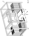
- FIG. 2 The drawing shows an embodiment of a depalletizing arrangement 38 with a device 9 for depalletizing, which is integrated in a gantry robot system 10, which is in an in Figure 2A apparent distribution center can be arranged with storage rows with pallet stacks on both sides and can be moved both in the vertical axis direction Y and in the transverse direction Z as well as in the orthogonal direction X along the storage aisle in order to have access to the pallets stored there with the with reference to the Fig. 1 explained different container types.
- the portal robot system 10 according to Fig. 2 is closer using Figure 2A so that the gantry robot system 10 includes the depalletizing arrangement 38, which has a support structure in the form of a portal 39, the gantry robot system 10 as a controllable robot being generally referred to as a manipulator 40, which accordingly includes the depalletizing arrangement 38.
- Figure 2B shows an enlarged representation of a section from Figure 2A with the rotary mount 41 with the two devices 9 arranged thereon for depalletizing the piece goods containers.
- a carrier 46 is provided on the support structure 39 in the form of the portal, which can be moved in the vertical axis direction Y of the support structure 39, extends in the transverse direction of the support structure 39 and on which a support arm 47 is provided which is positioned in Z Direction is movable relative to the carrier 46 and thus relative to the support structure 39, and, for example, with reference to FIG Figure 2A
- the drawing can be seen, can be extended so that the rotary receptacle 41 and thus the two devices 9 for depalletizing the piece goods containers can reach the containers on both sides of the storage aisle 45 in such a way that the containers arranged in the first row 48 of the shelf row 42 and also the In the second row 49 arranged containers of the shelf row 42 can be reached and the containers of the two rows 48, 49 of the second shelf row 43 can be reached from the rotary receptacle or the rotary head 41 with the two devices 9 for depalletizing the piece goods containers.
- the rotary head or the rotary mount 41 can be rotated about a vertical axis on the support arm 47 by means of an electric motor arranged on the rotary head and a toothed belt driven by it, as indicated by the arrow R in Figure 2B is shown.
- the devices 9 of the depalletizing arrangement 38 can reach all piece goods containers of the rows of shelves 42, 43 and by rotating the rotary head 41 by 180 degrees relative to the support arm 47 or to the carrier 46, the devices 9 for depalletizing the piece goods containers can each be aligned relative to the piece goods containers become.
- the rotary head 41 with the two devices 9 can also be moved in the Z direction relative to the support arm 47, namely also in both directions, which in FIG Figure 2B is designated by Z2.
- the movement of the rotary head 41 in the Z2 direction can thus be superimposed as a relative movement of the guide movement of the support arm 47 in the Z1 direction and the movement of the rotary head 41 is also possible independently of the movement of the support arm in the Z1 direction.
- a toothed belt drive with an electric motor and toothed belt is provided for moving the rotary head in the Z2 direction.
- Figure 2C The drawing shows that the support arm 47, which can be moved in the Z-direction on the carrier 46, has been extended in the direction of the row of shelves 42 and accordingly also the rotary head 41 with the two devices 9 for depalletizing the piece goods containers.
- the general cargo containers placed in the first row 48 of the shelf row 42 have already been depalletized and
- Figure 2C The drawing shows the devices 9 during depalletization of the piece goods containers arranged in the second row 49 of the shelf row 42.
- FIG. 2D The drawing shows that the rotary head 41 with the two devices 9 and the depalletized piece goods containers relative to the support arm 47 and also the support arm 47 itself has been moved in the direction of the shelf aisle 45 and the support 46 in the Y direction is still in height according to Figure 2C is located.
- the carrier 46 with the support arm 47 and the rotating head 41 and the devices 9 is then lowered in the Y direction so that the depalletized piece goods containers can be lowered onto the conveyor belts 23 and transferred to the conveyor belts 23, as in this case based on Figure 2E can be seen in the drawing.
- the conveyor belts 23 are in Fig. 2 and Figure 2A can be seen in the drawing.
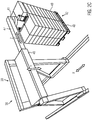
- FIG. 3 The drawing shows a schematic perspective illustration of the device 9 with the device already shown in FIG Fig. 2 explained coordinate system.
- the device 1 has a holding device 11 on which a suction device 12 is provided in the form of suction means 13 arranged at a distance from one another, which can be brought to a side wall of a disposable container 6, can be brought into contact there and via the generation of negative pressure can exert a suction force on the side wall of the disposable container 6 by means of a suction pump, which is not shown in detail, which is sufficient for the disposable container to be raised in a predetermined manner while maintaining the suction force to create a space between the raised disposable container and the disposable container or a pad arranged below it can, so that the support plate or undercarriage plate 14 can be moved into the space.
- a suction device 12 is provided in the form of suction means 13 arranged at a distance from one another, which can be brought to a side wall of a disposable container 6, can be brought into contact there and via the generation of negative pressure can exert a suction force on the side wall of the disposable container 6 by means of a suction pump, which is not shown in detail, which is sufficient for
- the device 1 also has a receptacle 15 on which two supports 16 extending away from the support plate 14 at an angle to it are arranged, on which a transverse support 17 is arranged displaceably in the vertical axis direction Y.
- An engagement device 18 which is designed to bring about a releasable engagement position with a handle recess of a container, is also arranged on the receptacle 15, as will be explained below.
- the device 9 also has a holding means 19 which is designed and provided for detachable arrangement or support on an upper edge region of a respective container, as will be explained in more detail below.
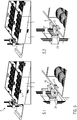
- Fig. 4 shows the device 9 in several representations when depalletizing disposable containers 6 with respective stacking lugs 7 in the corner area of the disposable containers 6.
- the device 9 is brought up to a side wall 20 of the disposable container 6 in such a way that the suction means 13 come to rest against the side wall 20.
- a pump not shown in detail
- negative pressure can be generated between the suction means 13 and the side wall 20, so that the side wall 20 and thus the disposable container 6 can be acted upon with a holding force which is sufficiently great that over a lifting of the holding device 11 with the suction device 12 formed thereon with the suction means 13, an intermediate space 21 can be formed between the disposable container 6 to be depalletized and the further disposable container 6 arranged below it.
- the front stacking lugs 7 facing the device are disengaged and the under-carriage plate or support plate 14 can be moved into the space 21 until the one-way container 6 to be depalletized rests on the under-carriage plate or support plate 14, as is the case in illustration 4.4 of the Fig. 4 can be seen.
- the plate 14 is pushed so far under the underside or lower surface 22 of the disposable container 6 until the center of gravity of the disposable container 6 with the fruit or vegetable products contained therein comes to rest on the plate 14, the rear stacking lugs 7 also disengaging .
- the suction device 12 can move together with the angularly adjusting configuration of the side wall 20 due to the lifting of the one-way container 6, that is to say change in angle relative to the vertical axis direction of the carrier 16, so that despite the angular change of the side wall 20 relative to the vertical axis direction the carrier 16 continues to have a slight negative pressure to hold the side wall 20 is sufficient.
- the device 9 can be displaced in the Z direction in such a way that the disposable container 6 is shown schematically with the reference numeral 23 in illustration 4.6 Conveyor belt 23 comes to rest. Then the support plate 14 can be pulled away from under the disposable container 6 and that again in the Z direction and the negative pressure applied to the suction device 12 is canceled, the depalletized disposable container 6 is, as shown in the illustration 4.7 of the Fig.
- the device 9 is, as can be seen in the illustration 4.8, ready for the next depalletizing process and can be moved with the suction device 12 in the direction of the side wall of another container 6 adjacent to the container 6 that has just been depalletized and the process of depalletizing this next container 6 can be carried out.
- Fig. 5 The drawing shows in several representations the process of depalletizing returnable containers 2, each of which has transverse side walls 4 with handle recesses 5. As it is based on the representations of the Fig. 5 As can be seen, the reusable containers 2 also have corresponding handle recesses 5 on the longitudinal side walls 3, so that with the device 9 according to the invention it is also possible to depalletize the reusable containers 2 from the longitudinal side walls 3.
- the device 9 is moved towards the transverse side wall 4 of the container 3 in the upper container position and the position of the handle recess 5 is detected via a sensor device and the engagement device 18 with the gripping finger 24 at such a height Y-direction positioned so that the gripping finger 24 can be moved into the handle recess 5 via a translatory movement in the Z-direction until the gripping finger 24 penetrates the handle recess 5, as shown in Figure 5.2 of the Fig. 5 can be seen.
- the rubber lip 27 can apply a holding force to the edge 25 from above, with any existing deformations of the edge region of the edge 25 being able to be compensated for by the elasticity of the rubber lip 27.
- FIG. 7 The drawing can also be seen, for this purpose, the holding means 19 provided with the rubber lip 27 in the form of a swivel holder 28 is lowered via an actuator 29 in the form of a pneumatic cylinder 30 in a swiveling movement on the swivel axis 31 onto the edge 25 of the reusable container 2, as shown can be seen from the double arrow 32.
- the holding means 19 of in Fig. 7 The device 9 shown has a receiving plate 34 in the form of a bracket 33, on which the rubber lip 27 is arranged on the front edge area and on a lower side 35 of the bracket 33 a schematically illustrated spring device 35 is provided, which acts as a stop damper and on which in the Gripping finger 24 located in the handle recess 5 can gently come to rest from above, so that the edge 25 can be clamped between the container, which can be moved in the Y direction to lift the container 2, as can be seen from the double arrow 36, and the rubber lip 27 without that a pressure force is exerted on the transverse side wall 4, and thus no damage to the fruit and vegetable products located in the container 2 can take place.
- the illustration 5.3 shows that by lifting the container 2 relative to the container 2 arranged underneath, an intermediate space 21 is formed into which the support plate or undercarriage plate 14 can be moved until it is in the position shown in illustration 5.4 relative to the underside 22 of the container and the container is completely lifted from the other container underneath.
- the bundle located on the support plate 14 can be separated from the bundle stack by a displacement movement of the device 9 carrying the bundle, as shown in Figure 5.5 of FIG Fig. 5 can be seen and then the support plate 14 by a corresponding displacement movement 5.6 to the left are pulled away from the bottom 22 of the container 2, so that the container 2 comes to rest on the conveyor belt 23 and is conveyed by this for further handling, as shown in the illustration 5.7 of Fig. 5 can be seen in the drawing.
- FIG. 6 The drawing shows a schematically illustrated folding box 8 with fruit and vegetable products located therein and a device 9 according to the present invention located in the clamping position with the upper edge 25 and the handle recess 5. Since the transverse side walls 4 of the folding box 8 are designed to be foldable, it is essential that these transverse side walls 4 are not subjected to a compressive force, as is the case with the known device explained at the beginning, so that the folding box type of container is not handled by the known device can be. In contrast to this, the device according to the invention can also be used to depalletize the folding box usually used for transporting fruit and vegetable products with the device according to the invention and according to the method according to the invention.
- the invention is characterized in that all known container types can be automatically depalletized with the device according to the invention and according to the method according to the invention, which are used for the transport of fruit and vegetable products in distribution centers and for further transport for sale to the buyer of the fruit and vegetable products .
- the device according to the invention and the method according to the invention ensure that depalletizing is made considerably easier the containers and for quick repositioning and very short dwell times in the distribution centers.
- the device according to the invention does not act on the side walls of the container with a clamping force or side force directed towards the interior of the container, the risk of damage to the sensitive fruit and vegetable products when depalletizing is eliminated. Likewise, the risk of the side walls of the container being torn open or impressed is eliminated.
- the respective position of the handle recesses of the container can be precisely detected via a sensor device and the gripping finger can thus be positioned exactly in the handle recess.
- the container By lifting the gripping finger with the holding means resting on the upper edge of the container, the container can be clamped without applying side force to the container walls and is supported from the underside via the under-carriage plate.
- non-returnable containers are supported from the underside of the base plate, so that centering tabs or centering corners on the containers are not damaged.
- Such disposable containers are lifted by the suction force applied by the suction device in that the suction device can be lifted on one side together with the container until the support plate or undercarriage plate is inserted into the space and the container rests on the carrier plate or undercarriage plate.
- the container By releasing the suction force and moving the support plate or undercarriage plate outwards, the container can then be set down on the removal belt and any short blowing impulse can remove any contamination from the suction device.
- the containers depalletized in this way be they one-way or reusable containers or also folding boxes with the fruit and vegetable products contained therein, are moved to a removal belt and placed on it in order to be able to be transported for further distribution in the distribution center.
- the respective containers only have to be lifted by about 25 mm in the Y direction and the gap that is thus created is sufficient to insert the undercarriage plate or support plate into the space to support the container to be depalletized from below.
- the base plate is moved beyond the center of gravity of the container in the Z-direction and in this way the container is supported from below on the one hand and an unintentional detachment of the container from the base plate during transport to the removal belt is eliminated on the other.
- piece goods containers were mentioned above which are filled with perishable goods, such as in particular fruit and vegetable products, this is not to be interpreted as a restriction, since empty piece goods containers can also be depalletized with the device and the method according to the invention, as well as piece goods containers that are filled with other goods, such as drugstore items or personal care products or goods of any other kind.
Landscapes
- Engineering & Computer Science (AREA)
- Mechanical Engineering (AREA)
- Transportation (AREA)
- Structural Engineering (AREA)
- Civil Engineering (AREA)
- Life Sciences & Earth Sciences (AREA)
- Geology (AREA)
- Robotics (AREA)
- De-Stacking Of Articles (AREA)
- Manipulator (AREA)
- Warehouses Or Storage Devices (AREA)
- Stacking Of Articles And Auxiliary Devices (AREA)
- Container Filling Or Packaging Operations (AREA)
- Hooks, Suction Cups, And Attachment By Adhesive Means (AREA)
- Specific Conveyance Elements (AREA)
- Load-Engaging Elements For Cranes (AREA)
Abstract
- des Herbeiführens eines lösbaren Eingriffs der Halteeinrichtung (18) mit einer Ausnehmung (5) einer Seitenwand (3, 4) des Gebindes (2, 6)
- Anheben des Gebindes (2, 6) mittels der Halteeinrichtung (18) zur Trennung des Auflagebereichs (22) des Gebindes (2, 6) zumindest entlang eines Teilbereichs von der Unterlage zur Herbeiführung eines Zwischenraums (21) zwischen dem Auflagebereich (22) und der Unterlage
wobei ein Haltemittel (19, 26, 27) mit einem oberen Randbereich (25) des Gebindes (2, 6) in lösbaren Kontakt gebracht wird.
Description
- Die vorliegende Erfindung betrifft ein Verfahren zum Depalettieren von stapelbaren Stückgutgebinden nach dem Oberbegriff des Anspruchs 1.
- Bei den vorstehend erwähnten stapelbaren Stückgutgebinden kann es sich um Einweggebinde in der Form von beispielsweise Kartons handeln oder auch um Mehrweggebinde, welche aus einem Kunststoffwerkstoff oder auch aus Kartonmaterial gebildet sind oder auch um Klappboxen, also Gebinden mit einklappbaren Seitenwänden. Die Gebinde können grundsätzlich eine beliebige Art von Artikeln beinhalten, welche beispielsweise zum täglichen Gebrauch oder Verzehr vorgesehen sind.
- Die vorstehend erwähnte Vielfalt an Gebinden ist oftmals im Bereich von Obst und Gemüse zu finden, Stückgütern also, die aufgrund ihrer Verderblichkeit im Verteilerzentrum schnell und trotzdem schonend gehandhabt werden müssen.
- Der Umschlag oder die Handhabung der mit Obst und Gemüseprodukten oder Salaten befüllten Stückgutgebinden findet oftmals in Palettenlagern statt, dort werden die erwähnten Produkte in den erwähnten Gebinden auf standardisierten Paletten angeliefert und müssen zur weiteren Handhabung der Gebinde von den Paletten entpalettiert oder depalettiert werden. Zu diesem Zweck werden in den erwähnten Palettenlagern oder Verteilerzentren für Obst und Gemüse die Gebinde von Hand depalettiert, also manuell von der Palette abgenommen, und das abgenommene Gebinde sodann auf eine andere Palette abgelegt werden.
- Es hat sich auch gezeigt, dass die Obst- und Gemüseprodukte in den Verteilerzentren in hinsichtlich der Abmessungen standardisierten Gebinden angeliefert werden, die üblicherweise eine Grundfläche von 600 mal 400 mm mit unterschiedlichen Höhen aufweisen oder eine Grundfläche von 300 mal 400 mm mit ebenfalls unterschiedlichen Höhen besitzen.
- Einweggebinde besitzen dabei oftmals im Bereich der Seiten oder Querkanten angeordnete Zentrierlaschen oder auch Stapelnasen, welche jeweils im Eckbereich der Oberkanten der oftmals aus Kartonmaterial gebildeten Einweggebinde angeordnet sind.
- Die Mehrweggebinde und Klappboxen besitzen dahingehend oftmals in den Seitenwänden oder Querwänden ausgebildete Handgriffausnehmungen oder Griffmulden, mit denen diese Mehrweggebinde und Klappboxen manuell angehoben werden können.
- Eine zusätzliche Problematik besteht bei den erwähnten Obst- und Gemüseprodukten darin, dass diese oftmals einen hohen Feuchteanteil aufweisen, was dafür sorgt, dass aus Kartonmaterial gebildete Gebinde beim Depalettieren von der Unterseite her unterstützt werden müssen, um eine Beschädigung des Gebindes zu vermeiden. Aber auch andere, in den Stückgutgebinden mit auch von den genannten Abmessungen abweichenden Abmessungen enthaltene Artikel, wie beispielsweise Schokolade, Fleisch, Fisch und Wurstwaren oder andere Lebensmittel oder auch Drogerieartikel oder dergleichen müssen bei der Handhabung der Stückgutgebinde mit Vorsicht behandelt werden, um die Inhalte nicht zu beschädigen, was auch voraussetzt, dass die Beschädigung des Gebindes an sich vermieden werden muss.
- Anhand der
DE 199 59 285 B4 sind ein Vakuum-Greifsystem zum Greifen eines Objekts und Handhabungsgerät zum Handhaben des Objekts bekannt geworden. Bei dem hier beschriebenen bekannten Vakuumgreifsystem ist an einem Ausleger eines Manipulators in der Form eines Industrieroboters ein Saugkopf mit mehreren Saugmitteln beschrieben, der an einer Seitenwand eines zu manipulierenden Objekts angesetzt wird und dieses mittels einer durch die Erzeugung von Unterdruck herbeigeführten Haltekraft fixieren kann. Zur weiteren Stabilisierung und Fixierung des zu manipulierenden Objekts besitzt dieses bekannte Vakuumgreifsystem im rechten Winkel zu dem Saugkopf angeordnet einen zweiten Saugkopf, der an der Oberseite oder Deckseite des zu manipulierenden Objekts in Anlage gebracht werden kann, um durch die Erzeugung von Unterdruck im Bereich des zweiten Saugkopfes eine Hebekraft auszuüben. - Das so angehobene Objekt kann dann stabilisiert werden, indem ein mechanischer Untergreifer in den Zwischenraum zwischen dem angehobenen Objekt und dem darunter befindlichen Objekt geschoben wird.
- Dieses bekannte Vakuumgreifsystem eignet sich nicht zum Depalettieren von Gebinden mit Obst- und Gemüseprodukten, da die Gebinde, in denen die Obst- und Gemüseprodukte in den Verteilerzentren auf Paletten angeliefert werden, keine Oberseiten aufweisen, an denen der zweite Saugkopf angeordnet werden könnte, sondern die Obst- und Gemüseprodukte aufnehmenden Gebinde oben beziehungsweise an der Oberseite regelmäßig offen sind.
- Anhand der
EP 2 874 925 B1 ist ein Greiferkopf zum Transport von Stückgutgebinden bekannt geworden, der eine Saugleiste aufweist, die mit einer Seitenwand des zu manipulierenden Gebindes in Kontakt gebracht werden kann, um durch die Erzeugung von Unterdruck eine Hebekraft auf das Stückgutgebinde auszuüben, um einen Zwischenraum zwischen dem Stückgutgebinde und dem darunterliegenden Gebinde zu schaffen, in den eine Trageplatte zur Unterstützung des zu manipulierenden Gebindes von unten her eingebracht werden kann. - Anhand eines ebenfalls bekannt gewordenen Greifersystems mit einem Industrieroboter mit Ausleger, an dem seitlich verstellbare Druckplatten angeordnet sind, ist bereits versucht worden, Stückgutgebinde zu depalettieren. Dieses bekannte Greifersystem ist aber aufgrund der Tatsache, dass das Stückgutgebinde über eine auf die Seitenwände des Gebindes von den Druckplatten ausgeübte Klemmkraft gehalten wird, nicht zum Depalettieren von Obst- und Gemüseprodukte enthaltenden Gebinden geeignet, da durch die Druckplatten die Einweggebinde gequetscht werden würden, was zu Druckstellen an den Obst- und Gemüseprodukten führen würde und diese dadurch beschädigt werden.
- Stückgutgebinde der erwähnten Art werden oft in Hochregallagern gelagert oder zwischengelagert, welche Regale oder Regalreihen zu beiden Seiten einer zum Betrieb eines Manipulators in der Form eines Roboters benötigten Lagergasse aufweisen, wobei der Manipulator von der Lagergasse ausgehend beide Regalreihen bedient.
- Ausgehend hiervon liegt der vorliegenden Erfindung die Aufgabe zugrunde, ein Verfahren zum Depalettieren von stapelbaren Stückgutgebinden bereit zu stellen, welche Obst- und Gemüseprodukte oder andere Artikel enthalten können.
- Die Erfindung weist zur Lösung dieser Aufgabe die im Anspruch 1 angegebenen Merkmale auf. Vorteilhafte Ausgestaltungen des Verfahrens sind in den weiteren Ansprüchen beschrieben.
- Lediglich der Erläuterung halber wird hier eine Depalettieranordnung beschrieben mit einem, eine Tragstruktur aufweisenden Manipulator und einer an der Tragstruktur relativ zum Manipulator bewegbar angeordneten Vorrichtung zum Depalettieren von stapelbaren Stückgutgebinden, wobei die Vorrichtung eine Halteeinrichtung mit daran angeordneten und zum lösbaren Saugeingriff mit einer Seitenwand des Gebindes ausgebildete Saugmittel und eine relativ zur Halteeinrichtung bewegbare Trageplatte zur Unterstützung des Gebindes aufweist und eine Aufnahme mit mindestens einem Träger besitzt, an der die Halteeinrichtung angeordnet ist, wobei die Vorrichtung eine Eingriffseinrichtung aufweist, die zum lösbaren Eingriff mit einer Ausnehmung einer Seitenwand des Gebindes ausgebildet ist und die Vorrichtung an einer relativ zur Tragstruktur drehbar angeordneten Drehaufnahme angeordnet ist.
- Die so geschaffene Depalettieranordnung besitzt also eine Tragstruktur in der Form beispielsweise eines Gestells, einer Aufnahme oder eines Aufbaus oder eines Rahmens oder eines Portals oder einer Gitterstruktur oder einer anderen Lastaufnahmestruktur, die ein Teil eines Manipulators in der Form eines Roboters, eines Portalroboters oder einer anderen steuerbaren Einheit sein kann, welche in einer Lagergasse einer Lageranordnung betrieben werden kann.
- Die Tragstruktur ist also ganz allgemein zur Aufnahme einer nachfolgend noch näher beschriebenen Vorrichtung zum Depalettieren von stapelbaren Stückgutgebinden vorgesehen und kann Teil oder Einheit oder Bauteil eines Manipulators sein, wie vorstehend beschrieben worden ist.
- Über die Anordnung der Vorrichtung zum Depalettieren von stapelbaren Stückgutgebinden an einer Aufnahme, welche eine Drehaufnahme oder ein Drehkopf sein kann, und zwar in einer Art und Weise, dass die Vorrichtung relativ zur Tragstruktur drehbar angeordnet ist, wird erreicht, dass die Vorrichtung zum Depalettieren von stapelbaren Stückgutgebinden beidseits der Lagergasse angeordnete, gelagerte oder zwischengelagerte Produktreihen mit den Stückgutgebinden erreichen kann und auf diese Weise an der Depalettieranordnung nicht beidseits der Tragstruktur eine Vorrichtung zum Depalettieren der stapelbaren Stückgutgebinde oder Vorrichtungen zum Depalettieren der stapelbaren Stückgutgebinde vorgesehen sein müssen, sondern mit einer Einheit oder einer Baugruppe, welche die Vorrichtung zum Depalettieren der Stückgutgebinde oder Vorrichtungen zum Depalettieren der Stückgutgebinde umfasst, die Lagerreihen mit Stückgutgebinden beidseits der Lagergasse von der einen Einheit oder Baugruppe erreicht oder erfasst oder bedient werden können.
- Um zu erreichen, dass die Vorrichtung zum Depalettieren der Stückgutgebinde oder die Vorrichtungen zum Depalettieren der Stückgutgebinde die Stückgutgebinde jeweils von der Zugriffsseite aus erreichen können, kann die an der Drehaufnahme vorgesehene Vorrichtung zum Depalettieren der Stückgutgebinde beziehungsweise können die an der Drehaufnahme vorgesehenen Vorrichtungen zum Depalettieren der Stückgutgebinde mittels der Drehaufnahme zu den Stückgutgebinden hin gedreht werden.
- Wenn also zunächst erste Stückgutgebinde auf einer ersten Seite der Lagergasse depalettiert werden und zu diesem Zweck die Drehaufnahme mit der Vorrichtung zum Depalettieren der Stückgutgebinde beziehungsweise den Vorrichtungen zum Depalettieren der Stückgutgebinde zu dieser ersten Seite der Lagergasse hin ausgerichtet ist, kann die Drehaufnahme zu einer zweiten Seite der Lagergasse hin um 180 Grad gedreht werden, um die Vorrichtung zum Depalettieren der Stückgutgebinde oder die Vorrichtungen zum Depalettieren der Stückgutgebinde zur zweiten Seite der Lagergasse hin auszurichten, so dass dann zweite Stückgutgebinde auf der zweiten Seite der Lagergasse mit der Vorrichtung zum Depalettieren der Stückgutgebinde oder den Vorrichtungen zum Depalettieren der Stückgutgebinde erreicht und depalettiert werden können.
- Es ist auch vorgesehen, dass die Tragstruktur einen in Hochachsrichtung der Tragstruktur bewegbaren Träger aufweist, an dem ein in Längsrichtung des Trägers bewegbarer Tragarm angeordnet ist und die Drehaufnahme mit der Vorrichtung relativ zum Tragarm drehbar angeordnet ist.
- Über den in Hochachsrichtung bewegbaren Träger kann ein von der Vorrichtung zum Depalettieren der Stückgutgebinde aufgenommenes Stückgutgebinde in Hochachsrichtung der Tragstruktur des Manipulators bewegt werden, um nach dem Depalettieren beispielsweise auf einer Fördereinrichtung abgelegt zu werden, um von dieser Fördereinrichtung zu einem anderen Handhabungsort befördert zu werden.
- Über den in Längsrichtung des Trägers bewegbaren Tragarm kann die Drehaufnahme mit der Vorrichtung oder den Vorrichtungen aus der Lagergasse in Richtung zu den ersten oder zweiten Lagerreihen mit den Stückgutgebinden bewegt werden, sodass die Vorrichtung beziehungsweise die Vorrichtungen die Stückgutgebinde auf beiden Seiten der Lagergasse erreichen können, um diese von den Paletten abzunehmen und beispielsweise der vorstehend erwähnten Fördereinrichtung zuzuführen.
- Es ist auch vorgesehen, dass die Drehaufnahme mit der Vorrichtung oder den Vorrichtungen relativ zur Tragstruktur in Längsrichtung der Tragstruktur bewegbar ausgebildet ist.
- Damit wird erreicht, dass die Drehaufnahme mit den an der Vorrichtung beziehungsweise den Vorrichtungen angeordneten Stückgutgebinden von den beidseits der Lagergasse angeordneten Lagerreihen, von denen die Stückgutgebinde soeben abgenommen worden sind, also depalettiert worden sind, beispielsweise in die Mitte der Lagergasse bewegt werden kann, also relativ zum Tragarm und auch relativ zum Träger, sodass dann über eine Vertikalbewegung des Trägers mit dem Tragarm und der Drehaufnahme mit der Vorrichtung oder den Vorrichtungen und den depalettierten Stückgutgebinden die Stückgutgebinde von der Vorrichtung oder den Vorrichtungen auf die vorstehend erwähnte Fördereinrichtung abgegeben werden können, um zu dem ebenfalls erwähnten anderen Handhabungsort weiter bewegt werden zu können.
- Zu diesem Zweck ist es von Vorteil dass die Drehaufnahme mit der Vorrichtung relativ zum Tragarm in Längsrichtung des Tragarms bewegbar ausgebildet ist. Damit kann die Drehaufnahme mit der Vorrichtung oder den Vorrichtungen unabhängig von der Längsbewegung des Tragarms relativ zum Träger bewegt werden, sodass also eine Relativbewegung der Drehaufnahme relativ zur Tragstruktur und auch relativ zum Tragarm möglich ist.
- Auch ist es vorgesehen, dass die Tragstruktur wenigstens zwei benachbart zueinander angeordnete Vorrichtungen aufweist, welche gemeinsam oder getrennt voneinander betätigbar ausgebildet sind.
- Es können also an der Tragstruktur zwei oder auch mehr als zwei Vorrichtungen zum Depalettieren von Stückgutgebinden benachbart zueinander angeordnet sein, welche also auch an der Drehaufnahme angeordnet sein können und diese Vorrichtungen können zum Depalettieren der Stückgutgebinde gemeinsam oder getrennt voneinander betätigt werden. Damit kann erreicht werden, dass beispielsweise bei zwei benachbart zueinander angeordneten Vorrichtungen zum Depalettieren der Stückgutgebinde beide Vorrichtungen gemeinsam betätigt werden können, um gleichzeitig zwei Stückgutgebinde oder auch mehrere nebeneinander angeordnete Stückgutgebinde zu depalettieren oder auch erreicht werden, dass von den beiden oder mehreren benachbarten Vorrichtungen zum Depalettieren der Stückgutgebinde nur eine einzelne oder einzelne der mehreren Vorrichtungen zum Depalettieren der Stückgutgebinde betätigt werden, also eine gezielte Auswahl der Vorrichtungen zum Depalettieren der Stückgutgebinde ermöglicht ist.
- Es ist auch vorgesehen, dass der Manipulator relativ zu einer den Manipulator tragenden Aufnahme bewegbar ausgebildet ist. Damit wird erreicht, dass der beispielsweise entlang einer Lagergasse bewegbare Manipulator in dieser mit einem Hallenboden als Aufnahme ausgestatteten Lagergasse entlang der Lagerreihe oder entlang der Lagerreihen verfahren werden kann, um Stückgutgebinde mit unterschiedlichen Inhalten oder Artikeln depalettieren zu können, und zwar aufgrund der Drehaufnahme zu beiden Seiten der Lagergasse.
- Auch ist es vorgesehen, dass der Tragarm und die Drehaufnahme unabhängig voneinander in Längsrichtung des Trägers bewegbar ausgebildet sind. Damit ist eine gezielte Ansteuerung der Drehaufnahme mit der Vorrichtung zum Depalettieren oder den Vorrichtungen zum Depalettieren der Stückgutgebinde möglich, und zwar unabhängig von der Längsbewegung des Tragarms am Träger der Tragstruktur des Manipulators.
- Über die an der Vorrichtung zum Depalettieren vorgesehenen Saugmittel kann ein Saugeingriff mit einer Seitenwand eines Gebindes herbeigeführt werden, indem die Saugmittel an die Seitenwand herangeführt werden, bei der es sich um eine längs verlaufende oder auch um eine quer verlaufende Wand des Gebindes handeln kann, sodass die Saugmittel mit der Seitenwand in Kontakt kommen und über eine Unterdruckbeaufschlagung der Saugmittel eine Haltekraft zwischen der Seitenwand und den Saugmitteln aufgebaut wird, die ausreichend dimensioniert ist, sodass über eine Verlagerung der Saugmittel in Hochachsrichtung der Seitenwand betrachtet das Gebinde soweit einseitig angehoben wird, dass zwischen dem angehobenen Gebinde und dem darunter angeordneten Gebinde ein Zwischenraum ausgebildet wird.
- Über dieses Anheben des Gebindes, bei dem es sich beispielsweise um ein Einweggebinde in der Form eines oben offenen Kartons handeln kann, in dem sich Obst oder Gemüse als Stückgut angeordnet befindet, wird ein Zwischenraum ausgebildet, der ausreichend dimensioniert ist, sodass die Trageplatte relativ zum angehobenen Gebinde verlagert werden kann, bis sie zumindest einen Teilbereich der Bodenfläche der Unterseite des Gebindes überlagert und auf diese Weise das Gebinde von unten her abstützt.
- Eine translatorische Bewegung der Trageplatte mit dem darauf angeordneten Gebinde sorgt so dafür, dass das Gebinde von der gestapelten Anordnung der verbliebenen Gebinden separiert und beispielsweise auf einer Bandeinrichtung zum weiteren Transport abgelegt werden kann.
- Wie es vorstehend bereits erwähnt wurde, können in dem Verteilerzentrum auch Stückgutgebinde in der Form von Mehrweggebinden oder von Klappboxen vorliegen, welche mit der erfindungsgemäßen Depalettieranordnung ebenfalls automatisch depalettiert werden können.
- Zu diesem Zweck besitzt die Vorrichtung eine Eingriffseinrichtung, die zum lösbaren Eingriff mit einer Ausnehmung einer Seitenwand des Gebindes ausgebildet ist.
- Bei der Ausnehmung kann es sich um eine Vertiefung in einer Seitenwand des Gebindes handeln, welche üblicherweise zur manuellen Handhabung des Gebindes vorgesehen ist, da das Gebinde bei der Befüllung des Gebindes vor Ort mit Obst- oder Gemüseprodukten oder Salaten, beispielsweise auf dem Feld oder im Gewächshaus, üblicherweise von Hand gehandhabt wird und somit solche Gebinde sowohl an den Längsseiten als an den Querseiten Ausnehmungen in der Form von Handgriffausnehmungen besitzen.
- Die somit befüllten Gebinde werden im Verteilerzentrum als gestapelte Stückgutgebinde angeliefert, und zwar auf einer üblichen Palette angeordnet, so dass die Palette beispielsweise mit einem Gabelstapler transportiert werden kann.
- Die auf diese Weise in Stapelanordnung vorliegenden Stückgutgebinde können mit der nach der hier ebenso vorgesehenen Vorrichtung ebenfalls automatisch depalettiert werden. Zu diesem Zweck kann die Eingriffseinrichtung einen lösbaren Eingriff mit einer Ausnehmung einer Seitenwand herbeiführen.
- Die Eingriffseinrichtung kann beispielsweise an der Aufnahme angeordnet sein und relativ zur Trageplatte in Hochachsrichtung bewegbar ausgebildet sein, sodass die Eingriffseinrichtung unter Aufrechterhaltung des lösbaren Eingriffs mit der Ausnehmung des Gebindes mit einer vorbestimmten Bewegung in Hochachsrichtung dafür sorgt, dass sich das Gebinde um eine der vorbestimmten Bewegung entsprechende Wegstrecke von dem darunter angeordneten Gebinde einseitig anheben lässt und auf diese Weise ein Zwischenraum zwischen der Unterseite des angehobenen Gebindes und der Oberseite des darunter befindlichen Gebindes ausgebildet wird.
- In zu vorstehend bereits beschriebener Weise ähnlicher Weise kann dann eine Trageplatte in den Zwischenraum bewegt werden, sodass das angehobene Gebinde auf der Trageplatte zu liegen kommt beziehungsweise die Trageplatte das angehobene Gebinde von unten her unterstützt und so eine Trennung zwischen dem angehobenen Gebinde und dem vormals darunter angeordneten Gebinde herbeigeführt wird.
- Nach einer Weiterbildung ist es vorgesehen, dass die Eingriffseinrichtung in mindestens eine Ebenenrichtung einer sich weitgehend im rechten Winkel zum Träger erstreckenden Ebene bewegbar ausgebildet ist. Auf diese Weise kann die Eingriffseinrichtung zum Eingriff mit der Ausnehmung der Seitenwand des Gebindes relativ zur Seitenwand bewegt werden. Auch ist die Eingriffseinrichtung in Hochachsrichtung bewegbar ausgebildet, so dass sie in Ausnehmungen von Gebinden mit unterschiedlicher Höhenerstreckung eingreifen kann. Die jeweilige Ausnehmung kann über eine Sensoreinrichtung erfasst werden.
- Bei der Ausnehmung kann es sich um eine mit einem die Seitenwand vollständig durchsetzenden Durchlass versehene Handgriffausnehmung handeln, sodass die Eingriffseinrichtung die Handgriffausnehmung durchsetzen kann und eine beispielsweise in vertikaler Richtung erfolgende Verlagerungsbewegung der Eingriffseinrichtung zum Anheben des sich mit der Eingriffseinrichtung in Eingriff befindendem zu depalettierenden Gebinde führt. Durch dieses Anheben des entsprechenden Gebindes wird der bereits erläuterte Zwischenraum zwischen der Unterseite des angehobenen Gebindes und der Oberseite des darunter befindlichen Gebindes ausgebildet, in welchen die Trageplatte eingeführt werden kann.
- Es ist nach einer Weiterbildung vorgesehen, dass die Eingriffseinrichtung ein Eingriffsmittel aufweist, welches zum lösbaren Eingriff mit einer Handgriffausnehmung einer Seitenwand des Gebindes ausgebildet ist. Bei dem Eingriffsmittel kann es sich beispielsweise um einen Greiffinger handeln, der in die Handgriffausnehmung eingeführt werden kann, sodass ein Anheben des Greiffingers zu einem einseitigen Anheben des Gebindes führt und auf diese Weise ein in einer Seitenansicht dreieckförmiger Zwischenraum ausgebildet wird, in den die Trageplatte eingeführt werden kann.
- Im Gegensatz zu der vorstehend beschriebenen bekannten Vorrichtung mit seitlich relativ zum Gebinde verlagerbaren Druckplatten wird von der Vorrichtung keinerlei Seitenkraft auf das Gebinde ausgeübt, sodass es auch nicht zu einer Druckbeaufschlagung der im Gebinde befindlichen Obst- und Gemüseprodukte kommen kann und diese empfindlichen Waren daher auch keine Druckstellen bekommen. Dies gilt auch insbesondere bei Klappboxen als Gebinde, da ansonsten die Gefahr eines unbeabsichtigten Einklappens der Seitenwände dieser Gebinde besteht mit der Folge einer Beschädigung der in den Gebinden aufgenommenen Artikel.
- Das von der Trageplatte von unten her unterstützte depalettierte Gebinde kann beispielsweise zu einem Transportband befördert werden und an dieses übergeben werden. Bereits während der Verlagerungsbewegung des Gebindes zum Transportband oder auch nach der Positionierung des Gebindes über dem Transportband kann das Eingriffsmittel aus dem lösbaren Eingriff mit der Ausnehmung der Seitenwand des Gebindes gelöst werden und sodann das depalettierte Gebinde auf dem Transportband abgesetzt werden.
- Die Vorrichtung ist auf diese Weise zur automatischen Depalettierung sowohl von Einweggebinden als auch von Mehrweggebinden ausgebildet und ebenso zur automatischen Depalettierung von Klappboxen, welche ebenfalls Ausnehmungen zur manuellen Handhabung besitzen, mit denen die Eingriffseinrichtung einen lösbaren Eingriff einnehmen kann. Auch Klappboxen können daher mit der erfindungsgemäßen Vorrichtung automatisiert depalettiert werden und zwar auf die gleiche Weise, wie dies vorstehend bereits mit Mehrweggebinden ausführlich erläutert wurde.
- Auf diese Weise kann die Vorrichtung alle bekannten Gebindearten automatisiert depalettieren, welche zum Transport von Obst- und Gemüseprodukten und zur Verteilung in Verteilerzentren und Weitertransport zur Verkaufsfiliale Verwendung finden.
- Es ist nach einer Weiterbildung auch vorgesehen, dass die Vorrichtung ein Haltemittel aufweist, welches zur lösbaren Anordnung an einem oberen Randbereich des Gebindes ausgebildet ist. Mit diesem Haltemittel kann das Gebinde für beispielsweise den Transport von der Palette zum Förderband zwischen dem die Handgriffausnehmung durchsetzenden Greiffinger und dem darüber befindlichen Randbereich des Gebindes in der Form eines beispielsweise Mehrweggebindes oder einer Klappbox fixiert werden. Zu diesem Zweck übt der Greiffinger auf den unteren Randbereich der Handgriffausnehmung eine geringe Hubkraft aus und das Haltemittel übt auf den oberhalb der Handgriffausnehmung befindlichen Randbereich des Gebindes eine geringe Haltekraft aus, sodass auf diese Weise das Gebinde im Bereich des Randbereichs ähnlich einem Zangengriff geklemmt wird und während des Transports auf der Trageplatte zum Förderband auf der Trageplatte nicht verrutschen kann und somit eine Lagesicherung des Gebindes relativ zur Trageplatte oder Unterfahrplatte erreicht wird.
- Es ist nach einer Weiterbildung vorgesehen, dass das Haltemittel eine streifenförmige oder leistenförmige Konfiguration aufweist und an einem zum Kontakt mit dem oberen Randbereich des Gebindes ausgebildeten Bereich mit einem elastisch ausgebildeten Auflagemittel versehen ist.
- Der Randbereich des Gebindes in der Form beispielsweise einer Mehrwegbox oder einer Klappbox oder eines anderen Mehrweggebindes oberhalb der Handgriffausnehmungen weist regelmäßig eine streifenförmige oder leistenförmige Konfiguration auf und das Haltemittel besitzt daher ebenfalls eine streifenförmige oder leistenförmige Konfiguration, um mit dem Gebinderandbereich in Klemmeingriff oder Halteeingriff gebracht werden zu können.
- Das elastisch ausgebildete Auflagemittel am Haltemittel greift daher von oben auf den Randbereich des Gebindes zu und sorgt aufgrund seiner elastisch nachgiebigen Konfiguration dafür, dass auch bei einer geringen Differenz zwischen der Sollposition und der Istposition des Haltemittels relativ zum oberen Randbereich ein sicheres Klemmen des Randbereichs des Gebindes zwischen der Eingriffseinrichtung in der Form beispielsweise des bereits erwähnten Greiffingers und des Haltemittels erreicht wird.
- Es ist nach einer Weiterbildung auch vorgesehen, dass das Haltemittel an einem an der Aufnahme insbesondere in Hochachsrichtung bewegbar vorgesehenen Querträger angeordnet ist und mittels eines Aktuators zur lösbaren Anordnung an dem streifenförmigen oder leistenförmigen Randbereich des Gebindes betätigbar ist.
- Durch die Anordnung des Haltemittels an dem in Hochachsrichtung der Aufnahme bewegbar vorgesehenen Querträger wird erreicht, dass unterschiedliche Gebindehöhen berücksichtigt werden können, indem die Höhe des jeweiligen Gebindes beispielsweise mittels einer Sensoreinrichtung erfasst wird oder aufgrund einem Steuerrechner bekannter vorbestimmter Höhe des Gebindes entsprechend positioniert wird und der Querträger demgemäß mit dem daran angeordneten Haltemittel entsprechend relativ zur Höhe der Seitenwand positioniert wird und sodann über ein Absenken des Haltemittels auf den oberen Randbereich des Gebindes ein sicheres Klemmen des Gebindes zwischen dem die Handgriffausnehmung durchsetzenden Greiffinger und dem mit dem elastisch ausgebildeten Auflagemittel versehenen Haltemittel erreicht wird.
- Nach einer Weiterbildung ist es vorgesehen, dass das Haltemittel entlang einer weitgehend quer zur Aufnahme vorgesehenen Schwenkachse angeordnet ist und mittels eines Aktuators zur lösbaren Anordnung an dem streifenförmigen oder leistenförmigen Randbereich des Gebindes an der Schwenkachse verschwenkbar betätigbar ist.
- Ähnlich wie dies soeben bereits erläutert wurde, kann auch auf diese Weise mit dem schwenkbar betätigbaren Haltemittel ein sicheres Klemmen des oberen Randbereichs des Gebindes zwischen dem Eingriffsmittel in der Form beispielsweise eines in der Ausnehmung des Gebindes angeordneten Greiffingers und dem leistenförmigen oder streifenförmigen Haltemittel erreicht werden, sodass das Gebinde während der Bewegung auf der Unterfahrplatte oder Trageplatte zum Transportband sicher gehaltert ist.
- Bei dem Aktuator kann es sich beispielsweise um einen Elektromotor, einen Pneumatikzylinder oder eine andere Betätigungseinrichtung handeln, welche zum Absenken des Haltemittels auf den oberen Randbereich des Gebindes und zum Anheben des Haltemittels vom Randbereich ausgebildet ist.
- Es ist nach einer Weiterbildung vorgesehen, dass das Haltemittel eine sich von der Aufnahme weg erstreckende Aufnahmeplatte aufweist, an welcher das Auflagemittel angeordnet ist. Über ein Absenken der Aufnahmeplatte mittels einer Vertikalbewegung oder einer Schwenkbewegung relativ zum Träger der Vorrichtung kann somit das Auflagemittel auf den oberen Randbereich des Gebindes abgesenkt werden und über eine Hubbewegung beziehungsweise Schwenkbewegung kann das Auflagemittel vom Randbereich wieder abgehoben werden, wenn das vereinzelte oder depalettierte Gebinde zum Weitertransport auf dem Bandförderer wieder freigegeben wird.
- Als eine vorteilhafte Ausführungsform des Aktuators kann beispielsweise eine pneumatisch betätigbare Kolbenzylindereinheit vorgesehen sein, mittels der das Haltemittel an dem streifenförmigen oder leistenförmigen Randbereich des Gebindes lösbar in Anlage gebracht werden kann. Dadurch findet ein Klemmen des Randbereichs zwischen dem Eingriffsmittel und dem Haltemittel statt, ohne aber das Gebinde im Bereich der Seitenwand mit einer Druckkraft zu beaufschlagen, welche zu Druckstellen an dem im Gebinde befindlichen Obst oder Gemüse führen kann.
- Die Erfindung sieht ein Verfahren der Depalettierung von stapelbaren Stückgutgebinden vor, bei dem ein einen unteren Auflagebereich aufweisendes Gebinde mittels einer Halteeinrichtung entlang mindestens eines Teilbereichs des Auflagebereichs von einer Unterlage abgehoben wird und eine Trageplatte unter den abgehobenen Teilbereich bewegt wird und ein körperlicher Kontakt des Teilbereichs zur Unterstützung des auf der Trageplatte mit dem Teilbereich aufliegenden Gebindes mit der Trageplatte herbei geführt wird, mit den Schritten:
- Herbeiführen eines lösbaren Eingriffs der Halteeinrichtung mit einer Ausnehmung einer Seitenwand des Gebindes
- Anheben des Gebindes mittels der Halteeinrichtung zur Trennung des Auflagebereichs des Gebindes zumindest entlang eines Teilbereichs von der Unterlage zur Herbeiführung eines Zwischenraums zwischen dem Auflagebereich und der Unterlage,
- Bei der Unterlage kann es sich beispielsweise um ein unterhalb des zu depalettierenden Gebindes weiteres Gebinde handeln oder auch um eine andere Unterlage in der Form beispielsweise einer Palette oder ganz einfach einer Auflagefläche.
- Über das Herbeiführen eines lösbaren Eingriffs der Halteeinrichtung mit der Ausnehmung einer Seitenwand des Gebindes wird erreicht, dass ein nachfolgendes Anheben des Gebindes mittels der Halteeinrichtung zur Trennung des Auflagebereichs des Gebindes zumindest entlang eines Teilbereichs von der Unterlage führt, wodurch ein Zwischenraum herbeigeführt wird und zwar zwischen dem Auflagebereich und der Unterlage, sodass dann eine Trageplatte oder Unterfahrplatte in diesem Zwischenraum bewegt werden kann, und sodann das zu depalettierende Gebinde auf der Trageplatte oder Unterfahrplatte aufliegt.
- Es ist dabei nach einer Weiterbildung des erfindungsgemäßen Verfahrens vorgesehen, dass die Halteeinrichtung in die Ausnehmung diese zumindest teilweise durchsetzend eingeführt wird derart, dass das Gebinde mittels der Halteeinrichtung mindestens entlang des Teilbereichs von der Unterlage anhebbar ist.
- Über dieses Anheben des Gebindes entlang des Teilbereichs wird ein zum Einführen der Trageplatte oder Unterfahrplatte ausreichender Zwischenraum zwischen der Unterseite des zu depalettierenden Gebindes und der Oberseite eines darunter angeordneten anderen Gebindes oder einer anderen Unterlage geschaffen.
- Es ist nach dem erfindungsgemäßen Verfahren vorgesehen, dass ein Haltemittel mit einem oberen Randbereich des Gebindes in lösbaren Kontakt gebracht wird. Dadurch kann ein Klemmen des oberen Randbereichs des Gebindes und damit des zu depalettierenden Gebindes zwischen der Halteeinrichtung, bei der es sich um eine Eingriffseinrichtung mit einem Greiffinger oder dergleichen handeln kann, und dem Haltemittel bewerkstelligt werden und auf diese Weise das Gebinde eine Lagesicherung erfahren, die in vorteilhafterweise während einer Bewegung des Gebindes zu einer Transporteinrichtung in der Form beispielsweise eines Bandförderers aufrechterhalten wird.
- Der vorstehend erwähnte Greiffinger kann daher in eine am Gebinde vorgesehene Ausnehmung in der Form beispielsweise einer Handgriffausnehmung eingeführt werden und sodann das Haltemittel von oben auf den oberen Randbereich des Gebindes abgesenkt werden, wodurch ein Klemmen des oberen Randbereichs des Gebindes zwischen dem Greiffinger und dem Haltemittel herbeigeführt wird, ohne mit dem im Gebinde befindlichen Obst oder Gemüse in Kontakt zu kommen und auch ohne eine Druckkraftbeaufschlagung von Obst oder Gemüse durchzuführen.
- Das so geklemmte Gebinde kann über eine Hubbetätigung der Halteeinrichtung in der Form beispielsweise des erwähnten Greiffingers zusammen mit dem auf dem Randbereich in Anlage befindlichen Haltemittel von der Unterlage getrennt werden und in den so geschaffenen Zwischenraum die Unterfahrplatte oder Trageplatte eingeführt werden. Alternativ hierzu kann die Unterfahrplatte oder Trageplatte auch in den durch Anheben der Halteeinrichtung geschaffenen Zwischenraum zwischen dem angehobenen Gebinde und dem darunter befindlichen Gebinde oder der Unterlage eingeführt werden und erst in einem Folgeschritt das Haltemittel auf den oberen Randbereich des Gebindes abgesenkt werden.
- Sodann wird das auf der Trageplatte oder der Unterfahrplatte aufliegende Gebinde von der Unterlage separiert und kann in einem weiteren Schritt in auf der Trageplatte oder der Unterfahrplatte aufliegender Weise weitertransportiert werden.
- Die Erfindung wird im Folgenden anhand der Zeichnung näher erläutert, diese zeigt in:
-
Fig. 1 vier Ansichten von unterschiedlichen Gebinden, welche zur Aufnahme von Obst- und Gemüseprodukten üblicherweise verwendet werden und mit der erfindungsgemäßen Depalettieranordnung und nach dem erfindungsgemäßen Verfahren automatisch depalettiert werden können; -
Fig. 2 eine schematische Darstellung einer als Portalroboter ausgebildeten Ausführungsform der erfindungsgemäßen Depalettieranordnung in einem Verteilerzentrum mit jeweiligen Lagerplätzen mit unterschiedlichen Gebinden, wie sie inFig. 1 der Zeichnung dargestellt wurden; -
Fig. 2A eine detailliertere Darstellung der Depalettieranordnung nachFig. 2 in einer Regalgasse mit beidseits der Regalgasse angeordneten Lagerreihen mit Stückgutgebinden; -
Fig. 2B eine vergrößerte Darstellung eines Ausschnitts der Depalettieranordnung nachFig. 2A ; -
Fig. 2C eine perspektivische Darstellung der Depalettieranordnung beim Depalettieren von Stückgutgebinden, die in einer hinteren Reihe eines Palettenstapels mit Stückgutgebinden angeordnet sind; -
Fig. 2D eine Darstellung ähnlich derjenigen nachFig. 2C , bei der die Vorrichtung zum Depalettieren mit der Drehaufnahme aus der auskragenden Stellung nachFig. 2C bereits zurückgezogen worden ist; -
Fig. 2E eine Darstellung ähnlich derjenigen nachFig. 2D , bei der der Träger mit der Drehaufnahme zur Ablage der depalettierten Stückgutgebinde auf eine Fördereinrichtung abgesenkt wurde; -
Fig. 3 eine perspektivische Darstellung einer schematisch dargestellten Ausführungsform einer Vorrichtung zum Depalettieren nach der vorliegenden Erfindung; -
Fig. 4 eine Abfolge von acht schematischen Darstellungen 4.1, 4.2, 4.3, 4.4, 4.5, 4.6, 4.7 und 4.8, welche die Vorrichtung beim Depalettieren von Einweggebinden mit Stapelnasen im jeweiligen Eckbereich der Gebinde zeigt; -
Fig. 5 eine Abfolge von acht schematischen Darstellungen 5.1, 5.2, 5.3, 5.4, 5.5, 5.6, 5.7 und 5.8, welche die Vorrichtung beim Depalettieren von Mehrweggebinden mit Handgriffausnehmungen an den Längswänden und an den Querwänden zeigt; -
Fig. 6 eine schematische und perspektivische Darstellung einer Klappbox mit der erfindungsgemäßen Vorrichtung und sich mit der Handgriffausnehmung der Klappbox in Eingriff befindendem Greiffinger sowie mit am oberen Randbereich der Klappbox aufliegenden Haltemittel; und -
Fig. 7 eine schematische Darstellung eines Mehrweggebindes mit dem bereits in Eingriff mit der Handgriffausnehmung befindendem Eingriffsmittel in einer Stellung, bevor sich das Haltemittel auf den oberen Randbereich absenkt. - Im Verteilerzentrum ankommende Gebinde mit Obst- und Gemüseprodukten werden auf Artikelpaletten angeliefert, die Gebinde aufweisen, welche mit jeweils gleichem Artikel befüllt sind, also beispielsweise Früchten oder auch Gemüseprodukten oder Salaten.
- Diese Gebinde müssen aufgrund der Verderblichkeit der Waren rasch und ohne Beschädigung der Waren von den Artikelpaletten, bei denen es sich um standardisierte Paletten handeln kann, abgenommen werden, um in so vereinzelter Weise über einen Bandförderer oder dergleichen in ein Zwischenlager transferiert werden zu können.
- Bislang wurden in den Verteilerzentren die Gebinde mit Obst- und Gemüseprodukten manuell depalettiert, da eine Vorrichtung zum automatischen Depalettieren von stapelbaren Stückgutgebinden bislang fehlte. Hier schafft die Erfindung nunmehr Abhilfe.
-
Fig. 1 der Zeichnung zeigt in vier Ansichten eine Vielzahl von Gebindetypen, die im Verteilerzentrum zu einer jeweiligen Artikelpalette zusammengefasst angeliefert werden und depalettiert werden müssen. - Die Darstellung 1.1 der
Fig. 1 zeigt eine standardisierte Palette 1 mit daran angeordneten Mehrweggebinden 2, welche sowohl an der jeweiligen Längsseitenwand 3 als auch an der jeweiligen Querseitenwand 4 eine jeweilige Handgriffausnehmung 5 aufweisen, da die Gebinde beim Produzenten der Obst- und Gemüseprodukte befüllt und auf den Paletten 1 in Stapelanordnung angeordnet werden und dies manuell stattfindet. - Während die Darstellung 1.1 Gebinde mit einer Grundfläche von beispielsweise 600 mal 400 mm zeigt, die in unterschiedlichen Höhen vorliegen können, je nachdem welche Produkte in den Gebinden aufgenommen werden, zeigt die Darstellung 1.2 eine Palette 1 mit Gebinden 2 mit einer Grundfläche von jeweils 300 mal 400 mm, und in einer von den Gebinden 2 nach der Darstellung 1.1 abweichender Höhe des jeweiligen Gebindes 2.
- Die Darstellung 1.3 der
Fig. 1 zeigt wiederum eine Palette 1 mit Einweggebinden 6 mit Stapelnasen 7 an der jeweiligen Querseite des Gebindes 6 und einer Grundfläche von 600 mal 400 mm. Die Darstellung 1.4 derFig. 1 zeigt eine Palette 1 mit Einweggebinden 1 mit einer jeweiligen Grundfläche von 300 mal 400 mm und geringerer Höhe als die Einweggebinde 6 nach der Darstellung 1.3 und Stapelnasen 7 im jeweiligen Eckbereich der Gebinde 6. -
Fig. 6 der Zeichnung schließlich zeigt ein Mehrweggebinde in der Form einer Klappbox 8, sodass ersichtlich ist, dass im Verteilerzentrum unterschiedliche Gebindetypen mit Obst- und Gemüseprodukten angeliefert werden und es erheblichen Bedarf für eine Vorrichtung gibt, die zur automatisierten Handhabung der Depalettierung aller dargestellten Gebindetypen ausgebildet ist. -
Fig. 2 der Zeichnung zeigt eine Ausführungsform einer Depalettieranordnung 38 mit einer Vorrichtung 9 zum Depalettieren, die in ein Portalrobotersystem 10 integriert ist, welches in einem inFig. 2A ersichtlichen Verteilerzentrum mit Lagerreihen mit beidseitigen Palettenstapeln angeordnet werden kann und sowohl in Hochachsrichtung Y als auch in Querrichtung Z als auch in hierzu orthogonaler Richtung X entlang der Lagergasse verfahren werden kann, um Zugriff zu haben auf die dort zwischengelagerten Paletten mit den unter Bezugnahme auf dieFig. 1 erläuterten unterschiedlichen Gebindetypen. - Das Portalrobotersystem 10 nach
Fig. 2 ist näher anhand vonFig. 2A dargestellt, sodass das Portalrobotersystem 10 die Depalettieranordnung 38 umfasst, welche eine Tragstruktur in der Form eines Portals 39 aufweist, wobei das Portalrobotersystem 10 als steuerbarer Roboter ganz allgemein als Manipulator 40 bezeichnet ist, der demgemäß die Depalettieranordnung 38 umfasst. - Wie es anhand von
Fig. 2A der Zeichnung ersichtlich ist, ist die näher anhand vonFig. 3 der Zeichnung ersichtliche Vorrichtung 9 zum Depalettieren der Stückgutgebinde 2, 6, 8 an einer Drehaufnahme 41 angeordnet, sodass über die Drehbetätigung der Drehaufnahme 41 mit bei der dargestellten Ausführungsform zwei an der Drehaufnahme 41 angeordneten Vorrichtungen 9 zum Depalettieren der Stückgutgebinde beide Regalreihen 42, 43 mit Palettenstapeln 44 mit den Stückgutgebinden, welche sich entlang der Lagergasse 45 erstrecken, erreicht werden können. -
Fig. 2B zeigt eine vergrößerte Darstellung eines Ausschnitts ausFig. 2A mit der Drehaufnahme 41 mit den zwei daran angeordneten Vorrichtungen 9 zum Depalettieren der Stückgutgebinde. - Wie es ohne weiteres ersichtlich ist, ist an der Tragstruktur 39 in der Form des Portals ein in Hochachsrichtung Y der Tragstruktur 39 bewegbarer Träger 46 vorgesehen, der sich in Querrichtung der Tragstruktur 39 erstreckt und an dem ein Tragarm 47 vorgesehen ist, der in Z-Richtung relativ zum Träger 46 und damit relativ zur Tragstruktur 39 bewegbar ist, und, wie dies beispielsweise anhand von
Fig. 2A der Zeichnung ersichtlich ist, ausgefahren werden kann, damit die Drehaufnahme 41 und damit die beiden Vorrichtungen 9 zum Depalettieren der Stückgutgebinde die Gebinde beidseits der Lagergasse 45 erreichen kann und zwar so, dass die in der ersten Reihe 48 angeordneten Gebinde der Regalreihe 42 und auch die in der zweiten Reihe 49 angeordneten Gebinde der Regalreihe 42 erreicht werden können und auch die Gebinde der beiden Reihen 48, 49 der zweiten Regalreihe 43 von der Drehaufnahme beziehungsweise dem Drehkopf 41 mit den beiden Vorrichtungen 9 zum Depalettieren der Stückgutgebinde erreicht werden können. Der Drehkopf beziehungsweise die Drehaufnahme 41 ist mittels eines am Drehkopf angeordneten Elektromotors und eines davon angetriebenen Zahnriemens um eine vertikale Achse an dem Tragarm 47 drehbar, wie dies durch den Pfeil R inFig. 2B gezeigt ist. - Über eine axiale Bewegung des Tragarms 47 relativ zum Träger 46, also eine Bewegung des Tragarms 47 mit dem daran angeordneten Drehkopf 41 mit den Vorrichtungen 9 in Z-Richtung nach
Fig. 2 der Zeichnung können also die Vorrichtungen 9 der Depalettieranordnung 38 alle Stückgutgebinde der Regalreihen 42, 43 erreichen und über eine Drehbetätigung des Drehkopfes 41 um 180 Grad relativ zum Tragarm 47 beziehungsweise zum Träger 46 können die Vorrichtungen 9 zum Depalettieren der Stückgutgebinde jeweils relativ zu den Stückgutgebinden ausgerichtet werden. - Wie es anhand von
Fig. 2B der Zeichnung ersichtlich ist, ist die Verfahrrichtung des Tragarms 47 in Z-Richtung in beide Richtungen mit Z1 bezeichnet. Zum Verfahren des Tragarms 47 in beide Richtungen ist ein Antrieb mit einer Zahnstange mit einem Antriebsritzel vorgesehen. - Der Drehkopf 41 mit den beiden Vorrichtungen 9 kann relativ zum Tragarm 47 ebenfalls in Z-Richtung bewegt werden und zwar ebenfalls in beide Richtungen, welche in
Fig. 2B mit Z2 bezeichnet ist. Die Verfahrbewegung des Drehkopfes 41 in Z2 Richtung kann also als Relativbewegung der Führungsbewegung des Tragarms 47 in Z1 Richtung überlagert werden und die Verfahrbewegung des Drehkopfes 41 ist auch unabhängig von der Verfahrbewegung des Tragarms in Z1 Richtung möglich. Zur Verfahrbewegung des Drehkopfes in Z2 Richtung ist ein Zahnriementrieb mit Elektromotor und Zahnriemen vorgesehen. -
Fig. 2C der Zeichnung zeigt, dass der am Träger 46 in Z-Richtung bewegbare Tragarm 47 in Richtung zur Regalreihe 42 ausgefahren wurde und demgemäß auch der Drehkopf 41 mit den beiden Vorrichtungen 9 zum Depalettieren der Stückgutgebinde. Die in der ersten Reihe 48 der Regalreihe 42 platzierten Stückgutgebinde wurden bereits depalettiert undFig. 2C der Zeichnung zeigt die Vorrichtungen 9 beim Depalettieren der in der zweiten Reihe 49 der Regalreihe 42 angeordneten Stückgutgebinde. -
Fig. 2D der Zeichnung zeigt, dass der Drehkopf 41 mit den beiden Vorrichtungen 9 und den depalettierten Stückgutgebinden relativ zum Tragarm 47 und auch der Tragarm 47 selbst in die Richtung zur Regalgasse 45 verfahren worden ist und sich der Träger 46 in Y-Richtung noch in der Höhe gemäßFig. 2C befindet. - In einem nächsten Schritt wird dann der Träger 46 mit dem Tragarm 47 und dem Drehkopf 41 und den Vorrichtungen 9 in Y-Richtung abgesenkt, sodass die depalettierten Stückgutgebinde auf die Förderbänder 23 abgesenkt werden können, und auf die Förderbänder 23 übergeben werden können, wie dies anhand von
Fig. 2E der Zeichnung ersichtlich ist. Die Förderbänder 23 sind inFig. 2 undFig. 2A der Zeichnung ersichtlich. -
Fig. 3 der Zeichnung zeigt eine schematische perspektivische Darstellung der Vorrichtung 9 mit dem bereits inFig. 2 erläuterten Koordinatensystem. - Die Vorrichtung 1 weist eine Halteeinrichtung 11 auf, an dem eine Saugeinrichtung 12 in der Form von im Abstand zueinander angeordneter Saugmittel 13 vorgesehen sind, welche an eine Seitenwand eines Einweggebindes 6 herangeführt werden können, dort in Anlage gebracht werden können und über die Erzeugung von Unterdruck mittels einer nicht näher dargestellten Saugpumpe eine Saugkraft auf die Seitenwand des Einweggebindes 6 ausüben können, welche ausreichend dafür ist, dass das Einweggebinde unter Aufrechterhaltung der Saugkraft zur Herbeiführung eines Zwischenraums zwischen dem angehobenen Einweggebinde und dem darunter angeordneten Einweggebinde oder einer Unterlage in vorbestimmter Weise angehoben werden kann, sodass die Trageplatte oder Unterfahrplatte 14 in den Zwischenraum verfahren werden kann.
- Darüber hinaus weist die Vorrichtung 1 auch eine Aufnahme 15 auf, an der zwei sich von der Trageplatte 14 im Winkel dazu weg erstreckende Träger 16 angeordnet sind, an denen ein Querträger 17 in Hochachsrichtung Y verschiebbar angeordnet ist.
- An der Aufnahme 15 ist auch eine Eingriffseinrichtung 18 angeordnet, welche zur Herbeiführung einer lösbaren Eingriffsstellung mit einer Handgriffausnehmung eines Gebindes ausgebildet ist, wie dies nachfolgend noch erläutert werden wird.
- Darüber hinaus besitzt die Vorrichtung 9 auch ein Haltemittel 19, welches zur lösbaren Anordnung oder Auflage an einem oberen Randbereich eines jeweiligen Gebindes ausgebildet und vorgesehen ist, wie dies nachfolgend noch näher erläutert werden wird.
-
Fig. 4 zeigt in mehreren Darstellungen die Vorrichtung 9 beim Depalettieren von Einweggebinden 6 mit jeweiligen Stapelnasen 7 im Eckbereich der Einweggebinde 6. - Wie es anhand der Darstellung 4.1 ersichtlich ist, wird die Vorrichtung 9 so an eine Seitenwand 20 des Einweggebindes 6 herangeführt, dass die Saugmittel 13 an der Seitenwand 20 zur Anlage kommen. Mittels einer nicht näher dargestellten Pumpe kann zwischen den Saugmitteln 13 und der Seitenwand 20 Unterdruck erzeugt werden, sodass die Seitenwand 20 und damit das Einweggebinde 6 ohne die Ausbildung einer Druckkraft auf die Seitenwand 20 mit einer Haltekraft beaufschlagt werden kann die ausreichend groß ist, sodass über ein Anheben der Halteeinrichtung 11 mit der daran ausgebildeten Saugeinrichtung 12 mit den Saugmitteln 13 ein Zwischenraum 21 zwischen dem zu depalettierenden Einweggebinde 6 und dem darunter angeordneten weiteren Einweggebinde 6 ausgebildet werden kann.
- Wie es anhand der Darstellung 4.3 ersichtlich ist, gelangen dabei die der Vorrichtung zugewandten vorderen Stapelnasen 7 außer Eingriff und die Unterfahrplatte oder Trageplatte 14 kann in den Zwischenraum 21 verschoben werden, bis das zu depalettierende Einweggebinde 6 an der Unterfahrplatte oder Trageplatte 14 aufliegt, wie dies in der Darstellung 4.4 der
Fig. 4 ersichtlich ist. Die Platte 14 wird dabei so weit unter die Unterseite oder untere Fläche 22 des Einweggebindes 6 geschoben, bis der Schwerpunkt des Einweggebindes 6 mit den darin befindlichen Obst- oder Gemüseprodukten auf der Platte 14 zu liegen kommt, dabei gelangen auch die hinteren Stapelnasen 7 außer Eingriff. - Wie es anhand der Darstellung 4.3 ersichtlich ist, nimmt die Saugeinrichtung 12 zur Seitenwand 20 des Einweggebindes 6 eine zusammen mit der Seitenwand 20 schräggestellte Konfiguration ein, d. h. die Saugeinrichtung 12 kann zusammen mit der sich durch das Anheben des Einweggebindes 6 winkeligen einstellenden Konfiguration der Seitenwand 20 mit bewegen, sich also im Winkel relativ zur Hochachsrichtung der Träger 16 verändern, sodass weiterhin trotz der Winkelveränderung der Seitenwand 20 relativ zur Hochachsrichtung der Träger 16 eine geringe Unterdruckbeaufschlagung zum Halten der Seitenwand 20 ausreichend ist.
- Sobald sich das Gebinde 6 auf der Trageplatte 14 angeordnet befindet, kann die Vorrichtung 9 in Z-Richtung verlagert werden und zwar so, dass das Einweggebinde 6 über einem in der Darstellung 4.6 schematisch mit dem Bezugszeichen 23 dargestellten Förderband 23 zu liegen kommt. Sodann kann die Trageplatte 14 unter dem Einweggebinde 6 weggezogen werden und zwar wieder in Z-Richtung und die Unterdruckbeaufschlagung der Saugeinrichtung 12 aufgehoben werden, das depalettierte Einweggebinde 6 wird, wie dies in der Darstellung 4.7 der
Fig. 4 ersichtlich ist, in X-Richtung weg befördert und die Vorrichtung 9 ist, wie dies in der Darstellung 4.8 ersichtlich ist, zum nächsten Depalettiervorgang bereit und kann mit der Saugeinrichtung 12 in Richtung zur Seitenwand eines dem soeben depalettierten Gebinde 6 benachbarten weiteren Gebinde 6 bewegt werden und der Vorgang des Depalettierens dieses nächsten Gebindes 6 durchgeführt werden. -
Fig. 5 der Zeichnung zeigt in mehreren Darstellungen den Vorgang des Depalettierens von Mehrweggebinden 2, welche jeweils Querseitenwände 4 mit Handgriffausnehmungen 5 aufweisen. Wie es anhand der Darstellungen derFig. 5 ersichtlich ist, besitzen die Mehrweggebinden 2 auch an den Längsseitenwänden 3 entsprechende Handgriffausnehmungen 5, sodass mit der erfindungsgemäßen Vorrichtung 9 auch ein Depalettieren der Mehrweggebinde 2 von den Längsseitenwänden 3 aus möglich ist. - Wie es anhand der Darstellung 5.1 ersichtlich ist, wird die Vorrichtung 9 an die Querseitenwand 4 des Gebindes 3 in der oberen Gebindelage heran bewegt und dabei über eine Sensoreinrichtung die Position der Handgriffausnehmung 5 erfasst und die Eingriffseinrichtung 18 mit dem Greiffinger 24 in einer solchen Höhe in Y-Richtung positioniert, dass der Greiffinger 24 über eine translatorische Bewegung in Z-Richtung in die Handgriffausnehmung 5 hinein bewegt werden kann, bis der Greiffinger 24 die Handgriffausnehmung 5 durchsetzt, wie dies anhand der Darstellung 5.2 der
Fig. 5 ersichtlich ist. - In einem nächsten Schritt wird, wie dies anhand der Darstellung 5.3 der
Fig. 5 ersichtlich ist, das Haltemittel 19 auf den oberen Rand 25 der Querseitenwand 4 abgesenkt, bis das anhand vonFig. 7 der Zeichnung ersichtliche elastisch ausgebildete Auflagemittel 26 in der Form einer Gummilippe 27 am oberen Rand 25 aufliegt. - Die Gummilippe 27 kann den Rand 25 von oben her mit einer Haltekraft beaufschlagen, wobei etwaige vorhandene Verformungen des Randbereichs des Rands 25 durch die Elastizität der Gummilippe 27 ausgeglichen werden können.
- Wie es anhand von
Fig. 7 der Zeichnung weiter ersichtlich ist, wird hierzu das mit der Gummilippe 27 versehene Haltemittel 19 in der Form eines Schwenkhalters 28 über einen Aktuator 29 in der Form eines Pneumatikzylinders 30 in einer Schwenkbewegung an der Schwenkachse 31 auf den Rand 25 des Mehrweggebindes 2 abgesenkt, wie dies anhand des Doppelpfeils 32 ersichtlich ist. - Das Haltemittel 19 der in
Fig. 7 dargestellten Vorrichtung 9 besitzt eine Aufnahmeplatte 34 in der Form eines Auslegers 33, an dem am vorderen Randbereich die Gummilippe 27 angeordnet ist und an einer unteren Seite 35 des Auslegers 33 ist eine schematisch dargestellte Federeinrichtung 35 vorgesehen, welche als Anschlagdämpfer und an dem sich in der Handgriffausnehmung 5 befindlichen Greiffinger 24 von oben her sanft zur Auflage kommen kann, sodass der Rand 25 zwischen dem in Y-Richtung zum Anheben des Gebindes 2 bewegbaren Gebinde, wie dies anhand des Doppelpfeils 36 ersichtlich ist, und der Gummilippe 27 geklemmt werden kann, ohne dass auf die Querseitenwand 4 eine Druckkraft ausgeübt wird, und somit auch keine Beschädigung der im Gebinde 2 befindlichen Obst- und Gemüseprodukte stattfinden kann. - Die Darstellung 5.3 zeigt, dass in den durch das Anheben des Gebindes 2 relativ zu dem darunter angeordneten Gebinde 2 ein Zwischenraum 21 ausgebildet wird, in den die Trageplatte oder Unterfahrplatte 14 bewegt werden kann, bis diese die in der Darstellung 5.4 ersichtliche Lage relativ zur Unterseite 22 des Gebindes einnimmt und das Gebinde so vollständig von dem darunter befindlichen weiteren Gebinde abgehoben ist.
- In einem nächsten Schritt kann das sich auf der Trageplatte 14 befindliche Gebinde durch eine Verlagerungsbewegung der das Gebinde tragenden Vorrichtung 9 vom Gebindestapel separiert werden, wie dies anhand der Darstellung 5.5 der
Fig. 5 ersichtlich ist und sodann die Trageplatte 14 durch eine entsprechende Verlagerungsbewegung gemäß der Darstellung 5.6 nach links von der Unterseite 22 des Gebindes 2 weggezogen werden, sodass das Gebinde 2 an dem Förderband 23 zur Auflage kommt und von diesem zur weiteren Handhabung befördert wird, wie dies anhand der Darstellung 5.7 derFig. 5 der Zeichnung ersichtlich ist. - Die Darstellung 5.8 der
Fig. 5 schließlich zeigt, dass nun eine nächste Depalettierung stattfinden kann und zwar hinsichtlich des zum soeben depalettierten Gebinde 2 benachbarten Gebinde 2, wozu die Vorrichtung den durch das Depalettieren des soeben depalettierten Gebindes 2 freigewordenen Raum 37 nutzt und in Z-Richtung bis zur Erfassung der Handgriffausnehmung 5 des benachbarten Gebindes 2 verfahren werden kann. -
Fig. 6 der Zeichnung zeigt eine schematisch dargestellte Klappbox 8 mit darin befindlichen Obst- und Gemüseprodukten und einer sich in Klemmstellung mit dem oberen Rand 25 und der Handgriffausnehmung 5 befindlichen Vorrichtung 9 nach der vorliegenden Erfindung. Da die Querseitenwände 4 der Klappbox 8 einklappbar ausgebildet sind, ist es von wesentlicher Bedeutung, dass diese Querseitenwände 4 nicht mit einer Druckkraft beaufschlagt werden, wie dies bei der eingangs erläuterten bekannten Vorrichtung der Fall ist, sodass die Gebindeart Klappbox von der bekannten Vorrichtung nicht gehandhabt werden kann. Im Gegensatz hierzu kann mit der erfindungsgemäßen Vorrichtung auch die zum Transport von Obst- und Gemüseprodukten üblicherweise verwendete Klappbox mit der erfindungsgemäßen Vorrichtung und nach dem erfindungsgemäßen Verfahren depalettiert werden. - Die Erfindung zeichnet sich dadurch aus, dass mit der erfindungsgemäßen Vorrichtung und nach dem erfindungsgemäßen Verfahren alle bekannten Gebindetypen automatisch depalettiert werden können, welche zum Transport von Obst- und Gemüseprodukten in Verteilerzentren und zum Weitertransport zum Verkauf an den Abnehmer der Obst- und Gemüseprodukten Verwendung finden.
- Da diese Gebinde, je nachdem mit welchen Produkt sie befüllt sind, eine Eigenmasse von bis zu 20 kg aufweist können, sorgen die erfindungsgemäße Vorrichtung und das erfindungsgemäße Verfahren für eine wesentliche Erleichterung bei der Depalettierung der Gebinde und für ein schnelles Umsetzen und sehr kurze Verweilzeiten in den Verteilerzentren.
- Dadurch, dass die Seitenwände der Gebinde durch die erfindungsgemäße Vorrichtung nicht mit einer in Richtung zum Innenraum des Gebindes gerichteten Klemmkraft oder Seitenkraft beaufschlagt werden, ist auch die Gefahr einer Beschädigung der empfindlichen Obst- und Gemüseprodukte beim Depalettieren beseitigt. Ebenso ist die Gefahr eines Aufreissens oder Eindrückens der Seitenwände des Gebindes beseitigt. Die jeweilige Lage der Handgriffausnehmungen des Gebindes können über eine Sensoreinrichtung exakt erfasst werden und der Greiffinger somit exakt in der Handgriffausnehmung positioniert werden.
- Über das Anheben des Greiffingers mit dem auf dem oberen Rand des Gebindes aufliegenden Haltemittel kann das Gebinde ohne Seitenkraftbeaufschlagung der Gebindewände geklemmt werden und wird über die Unterfahrplatte von der Unterseite her abgestützt. In ähnlicher Weise werden Einweggebinde über die Unterfahrplatte von der Unterseite her abgestützt, sodass an den Gebinden vorhandene Zentrierlaschen oder Zentrierecken nicht beschädigt werden. Solche Einweggebinde werden durch die von der Saugeinrichtung aufgebrachten Saugkraft angehoben, indem die Saugeinrichtung zusammen mit dem Gebinde einseitig angehoben werden kann, bis die Trageplatte oder Unterfahrplatte in den Zwischenraum eingeführt wird und somit das Gebinde auf der Trageplatte oder Unterfahrplatte aufliegt. Durch das Lösen der Saugkraft und der Herausbewegung der Trageplatte oder Unterfahrplatte kann das Gebinde dann auf dem Wegfuhrband abgesetzt werden und ein etwaiger kurzer Blasimpuls kann eventuelle Verunreinigungen von der Saugeinrichtung entfernen.
- Die auf diese Weise depalettierten Gebinde, seien dies Einweggebinde oder Mehrweggebinde oder auch Klappboxen mit den darin befindlichen Obst- und Gemüseprodukten werden zu einem Wegfuhrband bewegt und auf diesem abgesetzt, um zur weiteren Verteilung im Verteilerzentrum transportiert werden zu können.
- Mit der Saugeinrichtung oder dem Greiffinger müssen die jeweiligen Gebinde nur um etwa 25 mm in Y Richtung angehoben werden und der sich somit einstellende Zwischenraum ist ausreichend, um die Unterfahrplatte oder Trageplatte in den Zwischenraum zur Abstützung des zu depalettierenden Gebindes von unten her einzuführen. Die Unterfahrplatte wird über den Schwerpunkt des Gebindes hinaus in Z-Richtung bewegt und auf diese Weise wird das Gebinde einerseits von unten her abgestützt und andererseits ein unbeabsichtigtes Lösen des Gebindes von der Unterfahrplatte während des Transports zum Wegfuhrband beseitigt.
- Obwohl vorstehend von Stückgutgebinden gesprochen wurde, welche mit verderblichen Waren, wie insbesondere Obst- und Gemüseprodukten befüllt sind, ist dies nicht als Beschränkung auszulegen, da mit der erfindungsgemäßen Vorrichtung und dem erfindungsgemäßen Verfahren auch leere Stückgutgebinde depalettiert werden können, genauso wie auch Stückgutgebinde, die mit anderen Waren befüllt sind, wie beispielsweise Drogerieartikel oder Körperpflegeprodukte oder Waren aller anderer Art.
-
- 1. Aspekt: Depalettieranordnung (38) mit einem, eine Tragstruktur (39) aufweisenden Manipulator (40) und einer an der Tragstruktur relativ zum Manipulator bewegbar angeordneten Vorrichtung (9) zum Depalettieren von stapelbaren Stückgutgebinden (2, 6), wobei die Vorrichtung (9) eine Halteeinrichtung (11) mit daran angeordneten und zum lösbaren Saugeingriff mit einer Seitenwand (3, 4) des Gebindes (2, 6) ausgebildete Saugmittel (12, 13) und eine relativ zur Halteeinrichtung (11) bewegbare Trageplatte (14) zur Unterstützung des Gebindes (2, 6) aufweist, und eine Aufnahme (15) mit mindestens einem Träger (16) besitzt, an der die Halteeinrichtung (11) angeordnet ist, dadurch gekennzeichnet, dass die Vorrichtung (9) eine Eingriffseinrichtung (18) aufweist, die zum lösbaren Eingriff mit einer Ausnehmung (5) einer Seitenwand (3, 4) des Gebindes (2, 6) ausgebildet ist und die Vorrichtung (9) an einer relativ zur Tragstruktur (39) drehbar angeordneten Drehaufnahme (41) angeordnet ist.
- 2. Aspekt: Depalettieranordnung (38) nach Aspekt 1, dadurch gekennzeichnet, dass die Tragstruktur (39) einen in Hochachsrichtung der Tragstruktur (39) bewegbaren Träger (46) aufweist, an dem ein in Längsrichtung des Trägers (46) bewegbarer Tragarm (47) angeordnet ist und die Drehaufnahme (41) mit der Vorrichtung (9) relativ zum Tragarm (47) drehbar angeordnet ist.
- 3. Aspekt: Depalettieranordnung (38) nach Aspekt 1 oder 2, dadurch gekennzeichnet, dass die Drehaufnahme (41) mit der Vorrichtung (9) relativ zur Tragstruktur (39) in Längsrichtung der Tragstruktur (39) bewegbar ausgebildet ist.
- 4. Aspekt: Depalettieranordnung (38) nach Aspekt 2 oder 3, dadurch gekennzeichnet, dass die Drehaufnahme (41) mit der Vorrichtung (9) relativ zum Tragarm (47) in Längsrichtung des Tragarms (47) bewegbar ausgebildet ist.
- 5. Aspekt: Depalettieranordnung (38) nach einem der vorstehenden Aspekte, dadurch gekennzeichnet, dass die Tragstruktur (39) wenigstens zwei benachbart zueinander angeordnete Vorrichtungen (9) aufweist, welche gemeinsam oder getrennt voneinander betätigbar ausgebildet sind.
- 6. Aspekt: Depalettieranordnung (38) nach einem der vorstehenden Aspekte, dadurch gekennzeichnet, dass der Manipulator (40) relativ zu einer den Manipulator (40) tragenden Aufnahme bewegbar ausgebildet ist.
- 7. Aspekt: Depalettieranordnung (38) nach einem der Aspekte 2 bis 6, dadurch gekennzeichnet, dass der Tragarm (47) und die Drehaufnahme (41) unabhängig voneinander in Längsrichtung des Trägers (46) bewegbar ausgebildet sind.
- 8. Aspekt: Depalettieranordnung (38) nach einem der vorstehenden Aspekte, dadurch gekennzeichnet, dass die Eingriffseinrichtung (18) an der Aufnahme (15) angeordnet ist und relativ zur Trageplatte (14) in Hochachsrichtung bewegbar ausgebildet ist.
- 9. Aspekt: Depalettieranordnung (38) nach einem der vorstehenden Aspekte, dadurch gekennzeichnet, dass die Eingriffseinrichtung (18) in mindestens eine Ebenenrichtung einer sich weitgehend im rechten Winkel zum Träger (16) erstreckenden Ebene bewegbar ausgebildet ist.
- 10. Aspekt: Depalettieranordnung (38) nach einem der vorstehenden Aspekte, dadurch gekennzeichnet, dass die Eingriffseinrichtung (18) ein Eingriffsmittel (24) aufweist, das zum Eingriff mit einer Handgriffausnehmung (5) einer Seitenwand (3, 4) des Gebindes (2, 6) ausgebildet ist.
- 11. Aspekt: Depalettieranordnung (38) nach Aspekt 10, dadurch gekennzeichnet, dass das Eingriffsmittel (24) relativ zur Handgriffausnehmung (5) des Gebindes (2, 6) bewegbar ausgebildet ist derart, dass das Eingriffsmittel (24) in die Handgriffausnehmung (5) und diese zumindest teilweise durchsetzend bewegbar ist und aus der Handgriffausnehmung (5) heraus bewegbar ausgebildet ist.
- 12. Aspekt: Depalettieranordnung (38) nach einem der vorstehenden Aspekte, gekennzeichnet durch mindestens ein Haltemittel (19), welches zur lösbaren Anordnung an einem oberen Randbereich (25) des Gebindes (2, 6) ausgebildet ist.
- 13. Aspekt: Depalettieranordnung (38) nach Aspekt 12, dadurch gekennzeichnet dass das Haltemittel (19) eine streifenförmige oder leistenförmige Konfiguration aufweist und an einem zum Kontakt mit dem oberen Randbereich (25) des Gebindes (2, 6) ausgebildeten Bereich mit einem elastisch ausgebildeten Auflagemittel (26, 27) versehen ist.
- 14. Aspekt: Depalettieranordnung (38) nach Aspekt 12 oder 13, dadurch gekennzeichnet, dass das Haltemittel (19) an einem an der Aufnahme (15) vorgesehenen Querträger (17) angeordnet ist und mittels eines Aktuators (29) zur lösbaren Anordnung an dem streifenförmigen oder leistenförmigen Randbereich (25) des Gebindes (2, 6) betätigbar ist.
- 15. Aspekt: Depalettieranordnung (38) nach einem der Aspekte 12 bis 14, dadurch gekennzeichnet, dass das Haltemittel (19) entlang einer weitgehend quer zur Aufnahme (15) vorgesehenen Schwenkachse (31) angeordnet ist und mittels eines Aktuators (29) zur lösbaren Anordnung an dem streifenförmigen oder leistenförmigen Randbereich (25) des Gebindes (2, 6) an der Schwenkachse (31) verschwenkbar betätigbar ist.
- 16. Aspekt: Depalettieranordnung (38) nach einem der Aspekte 12 bis 15, dadurch gekennzeichnet, dass das Haltemittel (19) eine sich von der Aufnahme (15) weg erstreckende Aufnahmeplatte (34) aufweist, an welcher das Auflagemittel (26, 27) angeordnet ist.
- 17. Aspekt: Depalettieranordnung (38) nach einem der Aspekte 14 bis 16, dadurch gekennzeichnet, dass der Aktuator (29) eine pneumatisch betätigbare Kolbenzylindereinheit (30) aufweist, mittels der das Haltemittel (19) an dem streifenförmigen oder leistenförmigen Randbereich (25) des Gebindes (2, 6) lösbar in Anlage bringbar ist.
- Hinsichtlich vorstehend im Einzelnen nicht näher erläuterter Merkmale der Erfindung wird in übrigen ausdrücklich auf die Patentansprüche und die Zeichnung verwiesen.
-
- 1. Palette
- 2. Mehrweggebinde
- 3. Längsseitenwand
- 4. Querseitenwand
- 5. Handgriffausnehmung
- 6. Einweggebinde
- 7. Stapelnase
- 8. Klappbox
- 9. Vorrichtung
- 10. Portalrobotersystem
- 11. Halteeinrichtung
- 12. Saugeinrichtung
- 13. Saugmittel
- 14. Trageplatte, Unterfahrplatte
- 15. Aufnahme
- 16. Träger
- 17. Querträger
- 18. Eingriffseinrichtung
- 19. Haltemittel
- 20. Seitenwand
- 21. Zwischenraum
- 22. Unterseite
- 23. Förderband
- 24. Greiffinger
- 25. Rand
- 26. Auflagemittel
- 27. Gummilippe
- 28. Schwenkhalter
- 29. Aktuator
- 30. Pneumatikzylinder
- 31. Schwenkachse
- 32. Doppelpfeil
- 33. Ausleger
- 34. Aufnahmeplatte
- 35. Federeinrichtung
- 36. Doppelpfeil
- 37. Raum
- 38. Depalettieranordnung
- 39. Portal, Tragstruktur
- 40. Manipulator
- 41. Drehaufnahme, Drehkopf
- 42. Regalreihe
- 43. Regalreihe
- 44. Palettenstapel
- 45. Lagergasse
- 46. Träger
- 47. Tragarm
- 48. erste Reihe
- 49. zweite Reihe
- Pfeil R Drehbewegung
- Pfeil Z1 Verfahrbewegung in Z-Richtung
- Pfeil Z2 Verfahrbewegung in Z-Richtung
Claims (9)
- Verfahren der Depalettierung von stapelbaren Stückgutgebinden (2, 6), bei dem ein einen unteren Auflagebereich (22) aufweisendes Gebinde (2, 6) mittels einer Halteeinrichtung (18) entlang mindestens eines Teilbereichs des Auflagebereichs (22) von einer Unterlage abgehoben wird und eine Trageplatte (14) unter den abgehobenen Teilbereich bewegt wird, und ein körperlicher Kontakt des Teilbereichs zur Unterstützung des auf der Trageplatte (14) mit dem Teilbereich aufliegenden Gebindes (2, 6) mit der Trageplatte (14) herbei geführt wird, mit den Schritten- des Herbeiführens eines lösbaren Eingriffs der Halteeinrichtung (18) mit einer Ausnehmung (5) einer Seitenwand (3, 4) des Gebindes (2, 6)- Anheben des Gebindes (2, 6) mittels der Halteeinrichtung (18) zur Trennung des Auflagebereichs (22) des Gebindes (2, 6) zumindest entlang eines Teilbereichs von der Unterlage zur Herbeiführung eines Zwischenraums (21) zwischen dem Auflagebereich (22) und der Unterlagedadurch gekennzeichnet, dass ein Haltemittel (19, 26, 27) mit einem oberen Randbereich (25) des Gebindes (2, 6) in lösbaren Kontakt gebracht wird.
- Verfahren nach Anspruch 1, dadurch gekennzeichnet, dass die Halteeinrichtung (18) in die Ausnehmung (5) diese zumindest teilweise durchsetzend eingeführt wird derart, dass das Gebinde (2, 6) mittels der Halteeinrichtung (18) mindestens entlang des Teilbereichs von der Unterlage anhebbar ist.
- Verfahren nach Anspruch 1 oder 2, dadurch gekennzeichnet, dass die Trageplatte (14) in den Zwischenraum (21) bewegt wird.
- Verfahren nach einem der vorstehenden Ansprüche, dadurch gekennzeichnet, dass das auf der Trageplatte (14) aufliegende Gebinde (2, 6) von der Unterlage separiert wird.
- Verfahren nach einem der vorstehenden Ansprüche, dadurch gekennzeichnet, dass die Lage und/oder Position der Ausnehmung (5) mittels einer Sensoreinrichtung erfasst wird.
- Verfahren nach einem der vorstehenden Ansprüchen, dadurch gekennzeichnet, dass die Höhe des Gebindes (2, 6) mittels einer Sensoreinrichtung erfasst wird und ein Querträger (17) mit dem daran angeordneten Haltemittel (19, 26, 27) relativ zu der die Ausnehmung (5) aufweisenden Seitenwand (3, 4) des Gebindes (2, 6) positioniert wird und über ein Absenken des Haltemittels (19, 26, 27) auf den oberen Randbereich des Gebindes (2, 6) ein Klemmen des Gebindes (2, 6) zwischen dem Haltemittel (19, 26, 27) und einem die Ausnehmung (5) durchsetzenden Greiffinger (24) der Halteeinrichtung (18) herbeigeführt wird.
- Verfahren nach einem der vorstehenden Ansprüche, dadurch gekennzeichnet, dass das Gebinde (2, 6) über eine Hubbetätigung der Halteeinrichtung (18) zusammen mit dem auf dem Randbereich in Anlage befindlichen Haltemittel (19, 26, 27) von der Unterlage getrennt wird und in den Zwischenraum (21) die Trageplatte (14) eingeführt wird.
- Verfahren nach einem der Ansprüche 1 bis 6, dadurch gekennzeichnet, dass die Trageplatte (14) in den durch Anheben der Halteeinrichtung (18) geschaffenen Zwischenraum (21) zwischen dem angehobenen Gebinde (2, 6) und einem darunter befindlichen Gebinde (2, 6) oder der Unterlage eingeführt wird und erst in einem Folgeschritt das Haltemittel (19, 26, 27) auf den oberen Randbereich des Gebindes (2, 6) abgesenkt wird.
- Verfahren nach einem der vorstehenden Ansprüche, dadurch gekennzeichnet, dass das auf der Trageplatte (14) aufliegende Gebinde (2, 6) weiter transportiert wird.
Priority Applications (3)
| Application Number | Priority Date | Filing Date | Title |
|---|---|---|---|
| HRP20260188TT HRP20260188T1 (hr) | 2019-04-25 | 2019-11-08 | Postupak skidanja spremnika komadne robe pogodnih za naslagivanje s paleta |
| RS20260169A RS67747B1 (sr) | 2019-04-25 | 2019-11-08 | Postupak za uklanjanje složivih kontejnera za komadnu robu sa paleta |
| SI201931021T SI3858768T1 (sl) | 2019-04-25 | 2019-11-08 | Postopek za razlaganje vsebnikov za kosovno blago, ki jih je mogoče zlagati v skladovnico, s palet |
Applications Claiming Priority (3)
| Application Number | Priority Date | Filing Date | Title |
|---|---|---|---|
| DE102019110704.0A DE102019110704B3 (de) | 2019-04-25 | 2019-04-25 | Vorrichtung und Verfahren zum Depalettieren von stapelbaren Stückgutgebinden |
| DE102019128197.0A DE102019128197B4 (de) | 2019-04-25 | 2019-10-18 | Depalettieranordnung mit einer Vorrichtung zum Depalettieren von stapelbaren Stückgutgebinden und Verfahren zum Depalettieren von stapelbaren Stückgutgebinden |
| EP19207984.6A EP3730433B1 (de) | 2019-04-25 | 2019-11-08 | Depalettieranordnung mit einer vorrichtung zum depalettieren von stapelbaren stückgutgebinden und verfahren zum depalettieren von stapelbaren stückgutgebinden |
Related Parent Applications (2)
| Application Number | Title | Priority Date | Filing Date |
|---|---|---|---|
| EP19207984.6A Division EP3730433B1 (de) | 2019-04-25 | 2019-11-08 | Depalettieranordnung mit einer vorrichtung zum depalettieren von stapelbaren stückgutgebinden und verfahren zum depalettieren von stapelbaren stückgutgebinden |
| EP19207984.6A Division-Into EP3730433B1 (de) | 2019-04-25 | 2019-11-08 | Depalettieranordnung mit einer vorrichtung zum depalettieren von stapelbaren stückgutgebinden und verfahren zum depalettieren von stapelbaren stückgutgebinden |
Publications (2)
| Publication Number | Publication Date |
|---|---|
| EP3858768A1 true EP3858768A1 (de) | 2021-08-04 |
| EP3858768B1 EP3858768B1 (de) | 2025-11-26 |
Family
ID=68501419
Family Applications (4)
| Application Number | Title | Priority Date | Filing Date |
|---|---|---|---|
| EP21156034.7A Active EP3858768B1 (de) | 2019-04-25 | 2019-11-08 | Verfahren zum depalettieren von stapelbaren stückgutgebinden |
| EP19207984.6A Active EP3730433B1 (de) | 2019-04-25 | 2019-11-08 | Depalettieranordnung mit einer vorrichtung zum depalettieren von stapelbaren stückgutgebinden und verfahren zum depalettieren von stapelbaren stückgutgebinden |
| EP19207977.0A Active EP3730432B1 (de) | 2019-04-25 | 2019-11-08 | Vorrichtung und verfahren zum depalettieren von stapelbaren stückgutgebinden |
| EP19208345.9A Active EP3730434B1 (de) | 2019-04-25 | 2019-11-11 | Verfahren und system zur kommissionierung von auf artikelpaletten in einem palettenlager in stapelbaren stückgutgebinden bereit gestellter waren auf einer zielpalette |
Family Applications After (3)
| Application Number | Title | Priority Date | Filing Date |
|---|---|---|---|
| EP19207984.6A Active EP3730433B1 (de) | 2019-04-25 | 2019-11-08 | Depalettieranordnung mit einer vorrichtung zum depalettieren von stapelbaren stückgutgebinden und verfahren zum depalettieren von stapelbaren stückgutgebinden |
| EP19207977.0A Active EP3730432B1 (de) | 2019-04-25 | 2019-11-08 | Vorrichtung und verfahren zum depalettieren von stapelbaren stückgutgebinden |
| EP19208345.9A Active EP3730434B1 (de) | 2019-04-25 | 2019-11-11 | Verfahren und system zur kommissionierung von auf artikelpaletten in einem palettenlager in stapelbaren stückgutgebinden bereit gestellter waren auf einer zielpalette |
Country Status (12)
| Country | Link |
|---|---|
| EP (4) | EP3858768B1 (de) |
| AT (3) | AT522556B1 (de) |
| CH (4) | CH716125B1 (de) |
| DE (1) | DE102019110704B3 (de) |
| DK (4) | DK3730432T3 (de) |
| ES (4) | ES3066555T3 (de) |
| FI (3) | FI3858768T3 (de) |
| HR (4) | HRP20260499T1 (de) |
| LT (4) | LT3858768T (de) |
| PL (4) | PL3858768T3 (de) |
| RS (4) | RS67747B1 (de) |
| SI (4) | SI3730433T1 (de) |
Cited By (2)
| Publication number | Priority date | Publication date | Assignee | Title |
|---|---|---|---|---|
| EP4137281A1 (de) * | 2021-08-19 | 2023-02-22 | Swisslog AG | Palettieren und/oder depalettieren |
| AT526215A1 (de) * | 2022-06-08 | 2023-12-15 | Tgw Logistics Group Gmbh | Transfervorrichtung und Verfahren zum Handhaben von Packeinheiten |
Families Citing this family (23)
| Publication number | Priority date | Publication date | Assignee | Title |
|---|---|---|---|---|
| CN113879854B (zh) * | 2020-07-01 | 2023-05-30 | 广东格兰仕集团有限公司 | 一种薄板单层筛选装置 |
| CN112093645B (zh) * | 2020-10-13 | 2022-06-10 | 中源家居股份有限公司 | 一种家居产品用智能仓储系统堆垛方法及设备 |
| CN112623589A (zh) * | 2020-12-16 | 2021-04-09 | 吴兰 | 一种用于农产品产地初加工的可多层码垛的蔬菜保鲜贮藏装置 |
| EP4277864A1 (de) * | 2021-01-12 | 2023-11-22 | Premium Robotics GmbH | Anordnung zum kommissionieren von gebinden |
| DE202021102751U1 (de) * | 2021-05-19 | 2022-08-25 | Autefa Solutions Germany GmbH | Stapeleinrichtung |
| US12678942B2 (en) | 2021-06-08 | 2026-07-14 | Symbotic Canada, Ulc | Tool for palletizing mixed load products, palletizing robot including the tool, and method therefor |
| DE102021115950A1 (de) | 2021-06-21 | 2022-12-22 | Bayerische Motoren Werke Aktiengesellschaft | Depalettiervorrichtung zum Depalettieren von aufeinander gestapelten Ladungsträgern sowie Verfahren zum Depalettieren der Ladungsträger |
| CN113428659B (zh) * | 2021-07-28 | 2025-02-21 | 济南翼菲智能科技股份有限公司 | 一种立体式拆装盘机构 |
| CN113788316B (zh) * | 2021-09-13 | 2023-05-26 | 南京紫峰家具有限公司 | 一种智能药房自动取药设备及取药方法 |
| DE102021124545B4 (de) * | 2021-09-22 | 2025-08-07 | Stöcklin Logistik Ag | Vorrichtung und Verfahren zur Sequenzierung von Ladeeinheiten in einer vorbestimmten Reihenfolge |
| WO2023095049A1 (de) * | 2021-11-29 | 2023-06-01 | Ferag Ag | Vorrichtung zum beladungsmanagement von transporteinheiten eines fördersystems |
| CN114132761A (zh) * | 2021-12-08 | 2022-03-04 | 珠海格力智能装备有限公司 | 座板回收码垛装置 |
| CN114370148B (zh) * | 2021-12-17 | 2023-07-25 | 广东佳大建设工程有限公司 | 一种建筑用立式贴墙砖设备 |
| CN114314437B (zh) * | 2021-12-30 | 2023-11-03 | 佛山市海天(高明)调味食品有限公司 | 去托盘装置及送料系统 |
| CN114313951B (zh) * | 2021-12-31 | 2024-09-10 | 浙江杭可科技股份有限公司 | 一种简易无需顶升的存取货装置及托盘输送机构 |
| CN115332916B (zh) * | 2022-07-04 | 2026-06-19 | 江苏博之旺自动化设备有限公司 | 新能源汽车高压线束组件自动送料装置 |
| IT202200021105A1 (it) * | 2022-10-13 | 2024-04-13 | Picklap S R L | Sistema e veicolo di commissionamento per prelevare articoli da supporti di stoccaggio di tipo pallet ed organizzarli su un supporto di commissionamento di tipo pallet |
| DE102023104580A1 (de) * | 2023-02-24 | 2024-08-29 | Noyes Robotics GmbH | Wechselvorrichtung für ein modulares Lagersystem zum Wechseln von Austauschkörpern bei Behältern, Wechselstation mit einer Wechselvorrichtung und einer Vertikaltransportvorrichtung, modulares Lagersystem mit einer Wechselstation und Verfahren zum Wechseln von Austauschkörpern |
| AT527108A1 (de) * | 2023-03-20 | 2024-10-15 | Tgw Logistics Group Gmbh | Vorrichtung und Verfahren zur automatisierten Beladung eines Ladungsträgers mit einen Ladestapel bildenden Ladeeinheiten |
| CN116477327B (zh) * | 2023-04-30 | 2025-09-16 | 杭州名度智能制造有限公司 | 一种袋装货物转运系统 |
| GB202314987D0 (en) * | 2023-09-29 | 2023-11-15 | Ocado Innovation Ltd | De-palletiser and palletiser |
| CN118446382B (zh) * | 2024-07-05 | 2024-11-19 | 杭州灵西机器人智能科技有限公司 | 针对混码单层垛型的松弛优化方法、电子设备和存储介质 |
| CN118992832B (zh) * | 2024-10-23 | 2025-03-07 | 纽科伦(新乡)起重机有限公司 | 一种压力储罐巡检及堆垛两用起重机 |
Citations (11)
| Publication number | Priority date | Publication date | Assignee | Title |
|---|---|---|---|---|
| DE1907109A1 (de) * | 1969-02-13 | 1970-09-03 | Von Opel Dipl Ing Fritz | Verfahren und Vorrichtung zum Aufnehmen von beispielsweise auf Paletten gestapelten Flaschenkaesten |
| DE4427488A1 (de) * | 1994-08-03 | 1996-02-08 | Beumer Maschf Bernhard | Verfahren zum Palettieren von Stückgutteilen und Stückgutgreifer insbesondere für Roboter, insbesondere zur Paketpalettierung |
| EP0849199A1 (de) * | 1996-12-21 | 1998-06-24 | TOPACK Verpackungstechnik GmbH | Verfahren und Vorrichtung zum Entpalettieren von Artikeln |
| DE19959285B4 (de) | 1999-12-09 | 2008-01-31 | J. Schmalz Gmbh | Vakuum-Greifsystem zum Greifen eines Objekts und Handhabungsgerät zum Handhaben eines Objekts mit Hilfe eines Vakuum-Greifsystems |
| EP2384864A1 (de) * | 2010-04-28 | 2011-11-09 | IPR-Intelligente Peripherien für Roboter GmbH | Robotergreifer und Handhabungsroboter |
| DE202010012945U1 (de) * | 2010-11-19 | 2012-02-22 | Hubtex Maschinenbau Gmbh & Co. Kg | Glasplattentransportfahrzeug |
| EP2441709A1 (de) * | 2010-10-15 | 2012-04-18 | Prospect AB | Greifer zum Greifen von Palettengütern |
| DE102013005613A1 (de) * | 2013-04-04 | 2014-10-09 | Atlantic C Handels- Und Beratungs-Gmbh | Verfahren zur Entnahme von Stückgutgebinden von einem Stapel und Greiferkopf zur Durchführung des Verfahrens |
| US20150251319A1 (en) * | 2014-03-04 | 2015-09-10 | Fanuc Corporation | Container-carrying device using robot hand |
| EP3020515A1 (de) * | 2014-11-13 | 2016-05-18 | Kabushiki Kaisha Toshiba | Übertragungsvorrichtung und artikelentnahmeverfahren |
| US20180215540A1 (en) * | 2017-01-30 | 2018-08-02 | Kabushiki Kaisha Toshiba | Variable article holding device, transfer device, robot handling system, and method for controlling transfer device |
Family Cites Families (20)
| Publication number | Priority date | Publication date | Assignee | Title |
|---|---|---|---|---|
| US3523601A (en) * | 1967-03-02 | 1970-08-11 | Alvey Inc | Carton palletizing apparatus |
| DE2724978C2 (de) | 1977-06-02 | 1985-04-04 | Schaefer Förderanlagen- und Maschinenbau GmbH, 8043 Unterföhring | Vorrichtung zum Aufeinandersetzen von Kästen |
| DE7935243U1 (de) | 1979-12-14 | 1981-08-27 | Holstein Und Kappert Gmbh, 4600 Dortmund | Vorrichtung zum umsetzen von mit ausnmehmungen ausgestatteten stueckguetern |
| JPS6120286U (ja) * | 1984-07-13 | 1986-02-05 | 不二輸送機工業株式会社 | 筐体積層用ロボツトハンド |
| GB8726152D0 (en) * | 1987-11-07 | 1987-12-09 | Ledsham Eng Co Ltd | Stacking equipment |
| DE3835032A1 (de) * | 1988-10-14 | 1990-04-19 | Niepmann Traylift Transport | Verfahren und vorrichtung zum entstapeln von blockweise auf paletten gestapelten zuschnitten |
| DE3915139A1 (de) * | 1989-05-09 | 1990-11-15 | Focke & Co | Verfahren und anlage zum umordnen von sortenweise palettierten gegenstaenden zu gruppen bestimmter sortenzusammenstellung |
| DE4426615C1 (de) | 1994-07-27 | 1995-09-14 | Ludwig Stiny | Vorrichtung zum Stapeln oder Entstapeln von stapelbarem Gut |
| DE10123081C1 (de) * | 2001-05-11 | 2002-11-07 | Krones Ag | Drehvorrichtung |
| US20070280812A1 (en) * | 2006-05-17 | 2007-12-06 | Axium Inc. | Tool and method for mixed palletizing/depalletizing |
| AT507166B1 (de) | 2008-08-12 | 2010-11-15 | Moosburger Logistics Network & | Fördertechnikunterstützte kommissionierung von waren |
| DE102008039110A1 (de) * | 2008-08-21 | 2010-02-25 | Krones Ag | Greifervorrichtung zum gleichzeitigen Erfassen mehrerer Gebinde und/oder Kästen mit Getränkebehältern und Verfahren zur Justierung der Greifervorrichtung |
| DE102009056639A1 (de) * | 2009-12-02 | 2011-06-09 | Kuka Roboter Gmbh | Verfahren und Vorrichtung zur automatisierten Kommissionierung von Gebinden |
| JP5717007B2 (ja) * | 2012-11-19 | 2015-05-13 | 株式会社安川電機 | ロボットシステム、ロボットハンド、ロボット |
| JP6597061B2 (ja) * | 2014-09-02 | 2019-10-30 | 株式会社ダイフク | 物品搬送設備 |
| CN205363927U (zh) * | 2015-12-25 | 2016-07-06 | 广东水利电力职业技术学院 | 周转箱用的侧提底托式搬运机械手 |
| DE102016109310A1 (de) * | 2016-05-20 | 2017-11-23 | Deutsche Post Ag | Rutsche und Sortiereinrichtung sowie Verfahren zum Sortieren von Stückgut |
| DE102017112305A1 (de) * | 2017-01-20 | 2018-07-26 | Witron Vermögensverwaltungs Gmbh | Verfahren und vorrichtung zur kommissionierung von waren mit begrenzter haltbarkeit |
| EP3441327A1 (de) * | 2017-08-09 | 2019-02-13 | Air Vol, S.A. | Fahrbarer overhead-regalstapelkran |
| CH714115A1 (de) * | 2017-09-04 | 2019-03-15 | Ferag Ag | Förderanlage mit Funksystem. |
-
2019
- 2019-04-25 DE DE102019110704.0A patent/DE102019110704B3/de active Active
- 2019-04-29 CH CH00570/19A patent/CH716125B1/de not_active IP Right Cessation
- 2019-05-13 AT ATA170/2019A patent/AT522556B1/de active
- 2019-11-07 AT ATA360/2019A patent/AT522558B1/de active
- 2019-11-07 CH CH01409/19A patent/CH716129B1/de unknown
- 2019-11-07 CH CH00130/21A patent/CH717051B1/de unknown
- 2019-11-08 FI FIEP21156034.7T patent/FI3858768T3/fi active
- 2019-11-08 PL PL21156034.7T patent/PL3858768T3/pl unknown
- 2019-11-08 LT LTEP21156034.7T patent/LT3858768T/lt unknown
- 2019-11-08 LT LTEP19207977.0T patent/LT3730432T/lt unknown
- 2019-11-08 DK DK19207977.0T patent/DK3730432T3/da active
- 2019-11-08 SI SI201930940T patent/SI3730433T1/sl unknown
- 2019-11-08 DK DK21156034.7T patent/DK3858768T3/da active
- 2019-11-08 PL PL19207984.6T patent/PL3730433T3/pl unknown
- 2019-11-08 RS RS20260169A patent/RS67747B1/sr unknown
- 2019-11-08 HR HRP20260499TT patent/HRP20260499T1/hr unknown
- 2019-11-08 ES ES19207977T patent/ES3066555T3/es active Active
- 2019-11-08 DK DK19207984.6T patent/DK3730433T3/da active
- 2019-11-08 RS RS20260393A patent/RS67934B1/sr unknown
- 2019-11-08 ES ES21156034T patent/ES3060363T3/es active Active
- 2019-11-08 LT LTEP19207984.6T patent/LT3730433T/lt unknown
- 2019-11-08 EP EP21156034.7A patent/EP3858768B1/de active Active
- 2019-11-08 RS RS20250545A patent/RS66862B1/sr unknown
- 2019-11-08 FI FIEP19207984.6T patent/FI3730433T3/fi active
- 2019-11-08 SI SI201931021T patent/SI3858768T1/sl unknown
- 2019-11-08 SI SI201931044T patent/SI3730432T1/sl unknown
- 2019-11-08 HR HRP20250778TT patent/HRP20250778T1/hr unknown
- 2019-11-08 EP EP19207984.6A patent/EP3730433B1/de active Active
- 2019-11-08 PL PL19207977.0T patent/PL3730432T3/pl unknown
- 2019-11-08 FI FIEP19207977.0T patent/FI3730432T3/fi active
- 2019-11-08 EP EP19207977.0A patent/EP3730432B1/de active Active
- 2019-11-08 ES ES19207984T patent/ES3034781T3/es active Active
- 2019-11-08 HR HRP20260188TT patent/HRP20260188T1/hr unknown
- 2019-11-11 DK DK19208345.9T patent/DK3730434T3/da active
- 2019-11-11 PL PL19208345.9T patent/PL3730434T3/pl unknown
- 2019-11-11 ES ES19208345T patent/ES2920125T3/es active Active
- 2019-11-11 SI SI201930296T patent/SI3730434T1/sl unknown
- 2019-11-11 RS RS20220581A patent/RS63326B1/sr unknown
- 2019-11-11 EP EP19208345.9A patent/EP3730434B1/de active Active
- 2019-11-11 HR HRP20220923TT patent/HRP20220923T1/hr unknown
- 2019-11-11 LT LTEP19208345.9T patent/LT3730434T/lt unknown
- 2019-11-25 AT ATA379/2019A patent/AT522557B1/de active
- 2019-12-04 CH CH01547/19A patent/CH716130B1/de unknown
Patent Citations (12)
| Publication number | Priority date | Publication date | Assignee | Title |
|---|---|---|---|---|
| DE1907109A1 (de) * | 1969-02-13 | 1970-09-03 | Von Opel Dipl Ing Fritz | Verfahren und Vorrichtung zum Aufnehmen von beispielsweise auf Paletten gestapelten Flaschenkaesten |
| DE4427488A1 (de) * | 1994-08-03 | 1996-02-08 | Beumer Maschf Bernhard | Verfahren zum Palettieren von Stückgutteilen und Stückgutgreifer insbesondere für Roboter, insbesondere zur Paketpalettierung |
| EP0849199A1 (de) * | 1996-12-21 | 1998-06-24 | TOPACK Verpackungstechnik GmbH | Verfahren und Vorrichtung zum Entpalettieren von Artikeln |
| DE19959285B4 (de) | 1999-12-09 | 2008-01-31 | J. Schmalz Gmbh | Vakuum-Greifsystem zum Greifen eines Objekts und Handhabungsgerät zum Handhaben eines Objekts mit Hilfe eines Vakuum-Greifsystems |
| EP2384864A1 (de) * | 2010-04-28 | 2011-11-09 | IPR-Intelligente Peripherien für Roboter GmbH | Robotergreifer und Handhabungsroboter |
| EP2441709A1 (de) * | 2010-10-15 | 2012-04-18 | Prospect AB | Greifer zum Greifen von Palettengütern |
| DE202010012945U1 (de) * | 2010-11-19 | 2012-02-22 | Hubtex Maschinenbau Gmbh & Co. Kg | Glasplattentransportfahrzeug |
| DE102013005613A1 (de) * | 2013-04-04 | 2014-10-09 | Atlantic C Handels- Und Beratungs-Gmbh | Verfahren zur Entnahme von Stückgutgebinden von einem Stapel und Greiferkopf zur Durchführung des Verfahrens |
| EP2874925B1 (de) | 2013-04-04 | 2015-10-14 | Atlantic C Handels- und Beratungs GmbH | Greiferkopf zum transport von stückgutgebinden |
| US20150251319A1 (en) * | 2014-03-04 | 2015-09-10 | Fanuc Corporation | Container-carrying device using robot hand |
| EP3020515A1 (de) * | 2014-11-13 | 2016-05-18 | Kabushiki Kaisha Toshiba | Übertragungsvorrichtung und artikelentnahmeverfahren |
| US20180215540A1 (en) * | 2017-01-30 | 2018-08-02 | Kabushiki Kaisha Toshiba | Variable article holding device, transfer device, robot handling system, and method for controlling transfer device |
Cited By (4)
| Publication number | Priority date | Publication date | Assignee | Title |
|---|---|---|---|---|
| EP4137281A1 (de) * | 2021-08-19 | 2023-02-22 | Swisslog AG | Palettieren und/oder depalettieren |
| WO2023020796A1 (de) * | 2021-08-19 | 2023-02-23 | Swisslog Ag | Palettieren und/oder depalettieren |
| AT526215A1 (de) * | 2022-06-08 | 2023-12-15 | Tgw Logistics Group Gmbh | Transfervorrichtung und Verfahren zum Handhaben von Packeinheiten |
| AT526215B1 (de) * | 2022-06-08 | 2025-06-15 | Tgw Logistics Group Gmbh | Transfervorrichtung und Verfahren zum Handhaben von Packeinheiten |
Also Published As
Similar Documents
| Publication | Publication Date | Title |
|---|---|---|
| EP3730433B1 (de) | Depalettieranordnung mit einer vorrichtung zum depalettieren von stapelbaren stückgutgebinden und verfahren zum depalettieren von stapelbaren stückgutgebinden | |
| EP4144673B1 (de) | Transfervorrichtung zum entladen einer transportladehilfe, entladestation und kommissionierlager zum lagern und kommissionieren von waren | |
| DE102007046919B4 (de) | Greifer zum automatischen Ergreifen von Packeinheiten | |
| DE102007016727B4 (de) | Verfahren zum mehrlagigen Bestapeln eines Trägers | |
| EP2581328B1 (de) | Regalbediengerät und Kommissionierlager | |
| DE69512309T2 (de) | Verfahren und Vorrichtung zur Aufnahme abgepackter Güter | |
| EP2144831A1 (de) | Verfahren zum be- und entladen einer palette und entsprechender palettierer | |
| EP0482406A1 (de) | Vorrichtung zum Handhaben von Gegenständen, wie Kartons | |
| DE102009038124A1 (de) | Lager- und Kommissioniersystem mit einem universell einsetzbaren Winkelladungsträger | |
| EP2736810A2 (de) | Vorrichtung und verfahren zum entpacken und zuführen von flach gefalteten und aufrecht stehenden packungsmänteln | |
| DE102019128197B4 (de) | Depalettieranordnung mit einer Vorrichtung zum Depalettieren von stapelbaren Stückgutgebinden und Verfahren zum Depalettieren von stapelbaren Stückgutgebinden | |
| DE102014104470A1 (de) | Stapelkommissionierung | |
| WO2023156341A1 (de) | Verfahren und vorrichtung zum automatischen mehrlagigen bestapeln eines trägers mit packstücken | |
| DE68925448T2 (de) | Automatische Zufuhr- und Beladevorrichtung für bogenförmige Gegenstände | |
| DE102007036900B4 (de) | Verfahren zum Abstapeln oder Stapeln von Gebinden sowie Vorrichtung zum Durchführen dieses Verfahrens | |
| DE102009052345A1 (de) | Automatisierte Kommissioniervorrichtung und Verfahren zum automatisierten Kommissionieren von Büchern, Medien, Prospekten und ähnlichen Gegenständen | |
| DE3203757A1 (de) | Vorrichtung zum zwischenstapeln von gegenstaenden | |
| DE202019005286U1 (de) | Vorrichtung zum Depalettieren von stapelbaren Stückgutgebinden | |
| DE102020006488B3 (de) | Logistiksystem zum Zuführen von Lagerteilen von einem Lagerort zu einer Entnahmestelle | |
| EP2647577A1 (de) | Handhabeverfahren und -vorrichtung für Verpackungseinheiten |
Legal Events
| Date | Code | Title | Description |
|---|---|---|---|
| REG | Reference to a national code |
Ref country code: HR Ref legal event code: TUEP Ref document number: P20260188T Country of ref document: HR |
|
| PUAI | Public reference made under article 153(3) epc to a published international application that has entered the european phase |
Free format text: ORIGINAL CODE: 0009012 |
|
| STAA | Information on the status of an ep patent application or granted ep patent |
Free format text: STATUS: THE APPLICATION HAS BEEN PUBLISHED |
|
| STAA | Information on the status of an ep patent application or granted ep patent |
Free format text: STATUS: REQUEST FOR EXAMINATION WAS MADE |
|
| AC | Divisional application: reference to earlier application |
Ref document number: 3730433 Country of ref document: EP Kind code of ref document: P |
|
| AK | Designated contracting states |
Kind code of ref document: A1 Designated state(s): AL AT BE BG CH CY CZ DE DK EE ES FI FR GB GR HR HU IE IS IT LI LT LU LV MC MK MT NL NO PL PT RO RS SE SI SK SM TR |
|
| 17P | Request for examination filed |
Effective date: 20210728 |
|
| RBV | Designated contracting states (corrected) |
Designated state(s): AL AT BE BG CH CY CZ DE DK EE ES FI FR GB GR HR HU IE IS IT LI LT LU LV MC MK MT NL NO PL PT RO RS SE SI SK SM TR |
|
| P01 | Opt-out of the competence of the unified patent court (upc) registered |
Effective date: 20230517 |
|
| STAA | Information on the status of an ep patent application or granted ep patent |
Free format text: STATUS: EXAMINATION IS IN PROGRESS |
|
| 17Q | First examination report despatched |
Effective date: 20230928 |
|
| RIC1 | Information provided on ipc code assigned before grant |
Ipc: H01R 12/58 20110101ALN20240424BHEP Ipc: H01R 13/11 20060101ALI20240424BHEP Ipc: H01R 12/71 20110101ALI20240424BHEP Ipc: B65G 61/00 20060101ALI20240424BHEP Ipc: B65G 59/02 20060101ALI20240424BHEP Ipc: B65G 47/91 20060101ALI20240424BHEP Ipc: B65G 47/90 20060101AFI20240424BHEP |
|
| RIC1 | Information provided on ipc code assigned before grant |
Ipc: H01R 12/58 20110101ALN20240515BHEP Ipc: H01R 13/11 20060101ALI20240515BHEP Ipc: H01R 12/71 20110101ALI20240515BHEP Ipc: B65G 61/00 20060101ALI20240515BHEP Ipc: B65G 59/02 20060101ALI20240515BHEP Ipc: B65G 47/91 20060101ALI20240515BHEP Ipc: B65G 47/90 20060101AFI20240515BHEP |
|
| RIC1 | Information provided on ipc code assigned before grant |
Ipc: H01R 12/58 20110101ALN20240607BHEP Ipc: H01R 13/11 20060101ALI20240607BHEP Ipc: H01R 12/71 20110101ALI20240607BHEP Ipc: B65G 61/00 20060101ALI20240607BHEP Ipc: B65G 59/02 20060101ALI20240607BHEP Ipc: B65G 47/91 20060101ALI20240607BHEP Ipc: B65G 47/90 20060101AFI20240607BHEP |
|
| 17Q | First examination report despatched |
Effective date: 20240625 |
|
| GRAP | Despatch of communication of intention to grant a patent |
Free format text: ORIGINAL CODE: EPIDOSNIGR1 |
|
| STAA | Information on the status of an ep patent application or granted ep patent |
Free format text: STATUS: GRANT OF PATENT IS INTENDED |
|
| RIC1 | Information provided on ipc code assigned before grant |
Ipc: H01R 12/58 20110101ALN20250604BHEP Ipc: H01R 13/11 20060101ALI20250604BHEP Ipc: H01R 12/71 20110101ALI20250604BHEP Ipc: B65G 61/00 20060101ALI20250604BHEP Ipc: B65G 59/02 20060101ALI20250604BHEP Ipc: B65G 47/91 20060101ALI20250604BHEP Ipc: B65G 47/90 20060101AFI20250604BHEP |
|
| RIC1 | Information provided on ipc code assigned before grant |
Ipc: B65G 47/90 20060101AFI20250606BHEP Ipc: B65G 47/91 20060101ALI20250606BHEP Ipc: B65G 59/02 20060101ALI20250606BHEP Ipc: B65G 61/00 20060101ALI20250606BHEP Ipc: H01R 12/71 20110101ALI20250606BHEP Ipc: H01R 13/11 20060101ALI20250606BHEP Ipc: H01R 12/58 20110101ALN20250606BHEP |
|
| INTG | Intention to grant announced |
Effective date: 20250624 |
|
| GRAS | Grant fee paid |
Free format text: ORIGINAL CODE: EPIDOSNIGR3 |
|
| GRAA | (expected) grant |
Free format text: ORIGINAL CODE: 0009210 |
|
| STAA | Information on the status of an ep patent application or granted ep patent |
Free format text: STATUS: THE PATENT HAS BEEN GRANTED |
|
| AC | Divisional application: reference to earlier application |
Ref document number: 3730433 Country of ref document: EP Kind code of ref document: P |
|
| AK | Designated contracting states |
Kind code of ref document: B1 Designated state(s): AL AT BE BG CH CY CZ DE DK EE ES FI FR GB GR HR HU IE IS IT LI LT LU LV MC MK MT NL NO PL PT RO RS SE SI SK SM TR |
|
| REG | Reference to a national code |
Ref country code: CH Ref legal event code: F10 Free format text: ST27 STATUS EVENT CODE: U-0-0-F10-F00 (AS PROVIDED BY THE NATIONAL OFFICE) Effective date: 20251126 Ref country code: GB Ref legal event code: FG4D Free format text: NOT ENGLISH |
|
| REG | Reference to a national code |
Ref country code: DE Ref legal event code: R096 Ref document number: 502019014134 Country of ref document: DE |
|
| REG | Reference to a national code |
Ref country code: IE Ref legal event code: FG4D Free format text: LANGUAGE OF EP DOCUMENT: GERMAN |
|
| REG | Reference to a national code |
Ref country code: CH Ref legal event code: R17 Free format text: ST27 STATUS EVENT CODE: U-0-0-R10-R17 (AS PROVIDED BY THE NATIONAL OFFICE) Effective date: 20260204 Ref country code: NL Ref legal event code: FP |
|
| REG | Reference to a national code |
Ref country code: DK Ref legal event code: T3 Effective date: 20260204 |
|
| REG | Reference to a national code |
Ref country code: FI Ref legal event code: FGE |
|
| REG | Reference to a national code |
Ref country code: ES Ref legal event code: FG2A Ref document number: 3060363 Country of ref document: ES Kind code of ref document: T3 Effective date: 20260326 |
|
| REG | Reference to a national code |
Ref country code: HR Ref legal event code: T1PR Ref document number: P20260188 Country of ref document: HR |
|
| REG | Reference to a national code |
Ref country code: EE Ref legal event code: FG4A Ref document number: E025650 Country of ref document: EE Effective date: 20260223 |
|
| PG25 | Lapsed in a contracting state [announced via postgrant information from national office to epo] |
Ref country code: IS Free format text: LAPSE BECAUSE OF FAILURE TO SUBMIT A TRANSLATION OF THE DESCRIPTION OR TO PAY THE FEE WITHIN THE PRESCRIBED TIME-LIMIT Effective date: 20260326 |
|
| PG25 | Lapsed in a contracting state [announced via postgrant information from national office to epo] |
Ref country code: PT Free format text: LAPSE BECAUSE OF FAILURE TO SUBMIT A TRANSLATION OF THE DESCRIPTION OR TO PAY THE FEE WITHIN THE PRESCRIBED TIME-LIMIT Effective date: 20260326 |
|
| PG25 | Lapsed in a contracting state [announced via postgrant information from national office to epo] |
Ref country code: BG Free format text: LAPSE BECAUSE OF FAILURE TO SUBMIT A TRANSLATION OF THE DESCRIPTION OR TO PAY THE FEE WITHIN THE PRESCRIBED TIME-LIMIT Effective date: 20251126 |
|
| PG25 | Lapsed in a contracting state [announced via postgrant information from national office to epo] |
Ref country code: SM Free format text: LAPSE BECAUSE OF FAILURE TO SUBMIT A TRANSLATION OF THE DESCRIPTION OR TO PAY THE FEE WITHIN THE PRESCRIBED TIME-LIMIT Effective date: 20251126 |
|
| PG25 | Lapsed in a contracting state [announced via postgrant information from national office to epo] |
Ref country code: SK Free format text: LAPSE BECAUSE OF FAILURE TO SUBMIT A TRANSLATION OF THE DESCRIPTION OR TO PAY THE FEE WITHIN THE PRESCRIBED TIME-LIMIT Effective date: 20251126 |