EP3858532A1 - Dispositif d'alimentation en élément pour un appareil de placement et de soudage, un réseau d'élément et ensemble de mise à niveau pour le dispositif de placement et de soudage et procédé d'alimentation correspondant d'une pièce d'assemblage auxiliaire par soudage - Google Patents
Dispositif d'alimentation en élément pour un appareil de placement et de soudage, un réseau d'élément et ensemble de mise à niveau pour le dispositif de placement et de soudage et procédé d'alimentation correspondant d'une pièce d'assemblage auxiliaire par soudage Download PDFInfo
- Publication number
- EP3858532A1 EP3858532A1 EP20154411.1A EP20154411A EP3858532A1 EP 3858532 A1 EP3858532 A1 EP 3858532A1 EP 20154411 A EP20154411 A EP 20154411A EP 3858532 A1 EP3858532 A1 EP 3858532A1
- Authority
- EP
- European Patent Office
- Prior art keywords
- nest
- movement
- welding
- element nest
- auxiliary
- Prior art date
- Legal status (The legal status is an assumption and is not a legal conclusion. Google has not performed a legal analysis and makes no representation as to the accuracy of the status listed.)
- Pending
Links
- 238000003466 welding Methods 0.000 title claims abstract description 245
- 238000000034 method Methods 0.000 title claims description 33
- 230000008878 coupling Effects 0.000 claims abstract description 66
- 238000010168 coupling process Methods 0.000 claims abstract description 66
- 238000005859 coupling reaction Methods 0.000 claims abstract description 66
- 238000005304 joining Methods 0.000 claims abstract description 56
- 238000012546 transfer Methods 0.000 claims abstract description 42
- 238000007667 floating Methods 0.000 claims abstract description 31
- 230000000903 blocking effect Effects 0.000 claims description 10
- 230000008859 change Effects 0.000 claims description 7
- 230000008569 process Effects 0.000 claims description 7
- 230000000284 resting effect Effects 0.000 claims 1
- 238000010276 construction Methods 0.000 description 9
- 238000005516 engineering process Methods 0.000 description 5
- 230000002452 interceptive effect Effects 0.000 description 4
- 238000006073 displacement reaction Methods 0.000 description 3
- 230000003993 interaction Effects 0.000 description 3
- 238000013459 approach Methods 0.000 description 2
- 238000013461 design Methods 0.000 description 2
- 230000000694 effects Effects 0.000 description 2
- 238000004519 manufacturing process Methods 0.000 description 2
- 230000001960 triggered effect Effects 0.000 description 2
- 238000011144 upstream manufacturing Methods 0.000 description 2
- 230000001066 destructive effect Effects 0.000 description 1
- 238000001514 detection method Methods 0.000 description 1
- 238000011161 development Methods 0.000 description 1
- 230000018109 developmental process Effects 0.000 description 1
- 210000003746 feather Anatomy 0.000 description 1
- 238000009434 installation Methods 0.000 description 1
- 230000014759 maintenance of location Effects 0.000 description 1
- 238000012986 modification Methods 0.000 description 1
- 230000004048 modification Effects 0.000 description 1
- 238000002360 preparation method Methods 0.000 description 1
- 238000003825 pressing Methods 0.000 description 1
- 230000004044 response Effects 0.000 description 1
- 239000000725 suspension Substances 0.000 description 1
Images


Classifications
-
- B—PERFORMING OPERATIONS; TRANSPORTING
- B23—MACHINE TOOLS; METAL-WORKING NOT OTHERWISE PROVIDED FOR
- B23K—SOLDERING OR UNSOLDERING; WELDING; CLADDING OR PLATING BY SOLDERING OR WELDING; CUTTING BY APPLYING HEAT LOCALLY, e.g. FLAME CUTTING; WORKING BY LASER BEAM
- B23K11/00—Resistance welding; Severing by resistance heating
- B23K11/10—Spot welding; Stitch welding
- B23K11/11—Spot welding
-
- B—PERFORMING OPERATIONS; TRANSPORTING
- B23—MACHINE TOOLS; METAL-WORKING NOT OTHERWISE PROVIDED FOR
- B23K—SOLDERING OR UNSOLDERING; WELDING; CLADDING OR PLATING BY SOLDERING OR WELDING; CUTTING BY APPLYING HEAT LOCALLY, e.g. FLAME CUTTING; WORKING BY LASER BEAM
- B23K11/00—Resistance welding; Severing by resistance heating
- B23K11/002—Resistance welding; Severing by resistance heating specially adapted for particular articles or work
- B23K11/004—Welding of a small piece to a great or broad piece
- B23K11/0046—Welding of a small piece to a great or broad piece the extremity of a small piece being welded to a base, e.g. cooling studs or fins to tubes or plates
- B23K11/0053—Stud welding, i.e. resistive
-
- B—PERFORMING OPERATIONS; TRANSPORTING
- B23—MACHINE TOOLS; METAL-WORKING NOT OTHERWISE PROVIDED FOR
- B23K—SOLDERING OR UNSOLDERING; WELDING; CLADDING OR PLATING BY SOLDERING OR WELDING; CUTTING BY APPLYING HEAT LOCALLY, e.g. FLAME CUTTING; WORKING BY LASER BEAM
- B23K11/00—Resistance welding; Severing by resistance heating
- B23K11/30—Features relating to electrodes
- B23K11/31—Electrode holders and actuating devices therefor
- B23K11/314—Spot welding guns, e.g. mounted on robots
- B23K11/315—Spot welding guns, e.g. mounted on robots with one electrode moving on a linear path
-
- B—PERFORMING OPERATIONS; TRANSPORTING
- B23—MACHINE TOOLS; METAL-WORKING NOT OTHERWISE PROVIDED FOR
- B23K—SOLDERING OR UNSOLDERING; WELDING; CLADDING OR PLATING BY SOLDERING OR WELDING; CUTTING BY APPLYING HEAT LOCALLY, e.g. FLAME CUTTING; WORKING BY LASER BEAM
- B23K11/00—Resistance welding; Severing by resistance heating
- B23K11/002—Resistance welding; Severing by resistance heating specially adapted for particular articles or work
- B23K11/0026—Welding of thin articles
-
- B—PERFORMING OPERATIONS; TRANSPORTING
- B23—MACHINE TOOLS; METAL-WORKING NOT OTHERWISE PROVIDED FOR
- B23K—SOLDERING OR UNSOLDERING; WELDING; CLADDING OR PLATING BY SOLDERING OR WELDING; CUTTING BY APPLYING HEAT LOCALLY, e.g. FLAME CUTTING; WORKING BY LASER BEAM
- B23K11/00—Resistance welding; Severing by resistance heating
- B23K11/002—Resistance welding; Severing by resistance heating specially adapted for particular articles or work
- B23K11/004—Welding of a small piece to a great or broad piece
- B23K11/0066—Riveting
-
- B—PERFORMING OPERATIONS; TRANSPORTING
- B23—MACHINE TOOLS; METAL-WORKING NOT OTHERWISE PROVIDED FOR
- B23K—SOLDERING OR UNSOLDERING; WELDING; CLADDING OR PLATING BY SOLDERING OR WELDING; CUTTING BY APPLYING HEAT LOCALLY, e.g. FLAME CUTTING; WORKING BY LASER BEAM
- B23K11/00—Resistance welding; Severing by resistance heating
- B23K11/10—Spot welding; Stitch welding
- B23K11/11—Spot welding
- B23K11/115—Spot welding by means of two electrodes placed opposite one another on both sides of the welded parts
-
- B—PERFORMING OPERATIONS; TRANSPORTING
- B23—MACHINE TOOLS; METAL-WORKING NOT OTHERWISE PROVIDED FOR
- B23K—SOLDERING OR UNSOLDERING; WELDING; CLADDING OR PLATING BY SOLDERING OR WELDING; CUTTING BY APPLYING HEAT LOCALLY, e.g. FLAME CUTTING; WORKING BY LASER BEAM
- B23K11/00—Resistance welding; Severing by resistance heating
- B23K11/30—Features relating to electrodes
- B23K11/31—Electrode holders and actuating devices therefor
- B23K11/318—Supporting devices for electrode holders
-
- B—PERFORMING OPERATIONS; TRANSPORTING
- B23—MACHINE TOOLS; METAL-WORKING NOT OTHERWISE PROVIDED FOR
- B23K—SOLDERING OR UNSOLDERING; WELDING; CLADDING OR PLATING BY SOLDERING OR WELDING; CUTTING BY APPLYING HEAT LOCALLY, e.g. FLAME CUTTING; WORKING BY LASER BEAM
- B23K11/00—Resistance welding; Severing by resistance heating
- B23K11/36—Auxiliary equipment
-
- B—PERFORMING OPERATIONS; TRANSPORTING
- B23—MACHINE TOOLS; METAL-WORKING NOT OTHERWISE PROVIDED FOR
- B23K—SOLDERING OR UNSOLDERING; WELDING; CLADDING OR PLATING BY SOLDERING OR WELDING; CUTTING BY APPLYING HEAT LOCALLY, e.g. FLAME CUTTING; WORKING BY LASER BEAM
- B23K37/00—Auxiliary devices or processes, not specially adapted to a procedure covered by only one of the preceding main groups
- B23K37/02—Carriages for supporting the welding or cutting element
- B23K37/0211—Carriages for supporting the welding or cutting element travelling on a guide member, e.g. rail, track
-
- B—PERFORMING OPERATIONS; TRANSPORTING
- B23—MACHINE TOOLS; METAL-WORKING NOT OTHERWISE PROVIDED FOR
- B23K—SOLDERING OR UNSOLDERING; WELDING; CLADDING OR PLATING BY SOLDERING OR WELDING; CUTTING BY APPLYING HEAT LOCALLY, e.g. FLAME CUTTING; WORKING BY LASER BEAM
- B23K37/00—Auxiliary devices or processes, not specially adapted to a procedure covered by only one of the preceding main groups
- B23K37/04—Auxiliary devices or processes, not specially adapted to a procedure covered by only one of the preceding main groups for holding or positioning work
- B23K37/047—Auxiliary devices or processes, not specially adapted to a procedure covered by only one of the preceding main groups for holding or positioning work moving work to adjust its position between soldering, welding or cutting steps
-
- B—PERFORMING OPERATIONS; TRANSPORTING
- B23—MACHINE TOOLS; METAL-WORKING NOT OTHERWISE PROVIDED FOR
- B23P—METAL-WORKING NOT OTHERWISE PROVIDED FOR; COMBINED OPERATIONS; UNIVERSAL MACHINE TOOLS
- B23P19/00—Machines for simply fitting together or separating metal parts or objects, or metal and non-metal parts, whether or not involving some deformation; Tools or devices therefor so far as not provided for in other classes
- B23P19/001—Article feeders for assembling machines
- B23P19/006—Holding or positioning the article in front of the applying tool
-
- F—MECHANICAL ENGINEERING; LIGHTING; HEATING; WEAPONS; BLASTING
- F16—ENGINEERING ELEMENTS AND UNITS; GENERAL MEASURES FOR PRODUCING AND MAINTAINING EFFECTIVE FUNCTIONING OF MACHINES OR INSTALLATIONS; THERMAL INSULATION IN GENERAL
- F16B—DEVICES FOR FASTENING OR SECURING CONSTRUCTIONAL ELEMENTS OR MACHINE PARTS TOGETHER, e.g. NAILS, BOLTS, CIRCLIPS, CLAMPS, CLIPS OR WEDGES; JOINTS OR JOINTING
- F16B2/00—Friction-grip releasable fastenings
- F16B2/20—Clips, i.e. with gripping action effected solely by the inherent resistance to deformation of the material of the fastening
- F16B2/22—Clips, i.e. with gripping action effected solely by the inherent resistance to deformation of the material of the fastening of resilient material, e.g. rubbery material
- F16B2/24—Clips, i.e. with gripping action effected solely by the inherent resistance to deformation of the material of the fastening of resilient material, e.g. rubbery material of metal
- F16B2/241—Clips, i.e. with gripping action effected solely by the inherent resistance to deformation of the material of the fastening of resilient material, e.g. rubbery material of metal of sheet metal
- F16B2/245—Clips, i.e. with gripping action effected solely by the inherent resistance to deformation of the material of the fastening of resilient material, e.g. rubbery material of metal of sheet metal external, i.e. with contracting action
-
- F—MECHANICAL ENGINEERING; LIGHTING; HEATING; WEAPONS; BLASTING
- F16—ENGINEERING ELEMENTS AND UNITS; GENERAL MEASURES FOR PRODUCING AND MAINTAINING EFFECTIVE FUNCTIONING OF MACHINES OR INSTALLATIONS; THERMAL INSULATION IN GENERAL
- F16B—DEVICES FOR FASTENING OR SECURING CONSTRUCTIONAL ELEMENTS OR MACHINE PARTS TOGETHER, e.g. NAILS, BOLTS, CIRCLIPS, CLAMPS, CLIPS OR WEDGES; JOINTS OR JOINTING
- F16B5/00—Joining sheets or plates, e.g. panels, to one another or to strips or bars parallel to them
- F16B5/08—Joining sheets or plates, e.g. panels, to one another or to strips or bars parallel to them by means of welds or the like
-
- B—PERFORMING OPERATIONS; TRANSPORTING
- B21—MECHANICAL METAL-WORKING WITHOUT ESSENTIALLY REMOVING MATERIAL; PUNCHING METAL
- B21J—FORGING; HAMMERING; PRESSING METAL; RIVETING; FORGE FURNACES
- B21J15/00—Riveting
- B21J15/10—Riveting machines
- B21J15/30—Particular elements, e.g. supports; Suspension equipment specially adapted for portable riveters
- B21J15/32—Devices for inserting or holding rivets in position with or without feeding arrangements
Definitions
- the present invention relates to an element feed device of a setting-welding device for a welding auxiliary joining part with a head and a shaft.
- the present invention also relates to an element nest of a welding auxiliary joining part for a setting-welding device, as well as a setting-welding device which is equipped with the element feed device and / or the mentioned element nest.
- the present invention also relates to a retrofit kit for an element feed device and an element nest for an existing set-welding device.
- methods of feeding an auxiliary welding part to a joint in a setting / welding device are defined.
- the respective feed method uses the above-mentioned element feed device and / or the element nest.
- auxiliary welding parts are supplied via sometimes very complex element supply systems.
- the element feed systems are complex in this context because the paths between a transfer unit for the auxiliary welding part and the joint must be bridged with the aid of several drives.
- it is necessary that the positioning of the element feed device on the transfer unit for the auxiliary welding part and at the joint for transferring the auxiliary welding part to the electrode die must be secured with sufficient sensors.
- a set-welding device which is characterized by a structurally complex transfer and supply of an auxiliary welding part.
- an auxiliary welding part is first transferred from one clamp arrangement to a second clamp arrangement before the auxiliary welding part is fed to the joint.
- Complex in that the clamp's own sensors and drives handle the transfer of each Must ensure welding auxiliary joining part. Since the auxiliary welding part is transferred away from the joint under the electrode stamp, several drives are also required for a feed to the joint. These drives act in at least two different directions of movement. This requires the necessary control electronics, sensors and installation space for drives and sensors, which overall have a disadvantageous effect on the interfering contour of the set-welding device.
- the auxiliary welding part is blown directly to an element nest under the electrode stamp.
- This construction is based on the exact alignment of the element nest at the end of the profile channel to the element stamp.
- the profile channel has a large interfering contour.
- the profile channel with its interfering contour must be positioned appropriately in order to bring the element nest under the electrode stamp.
- it is necessary that the profile channel is removed from the electrode die before a welded connection can be made.
- complex and precisely coordinated sensors and drive technology are also required. Because neither the element nest itself nor the profile channel connected to it allow the compensation of tolerances in the alignment between the electrode stamp and the auxiliary welding part.
- EP 3 199 288 A2 discloses a set-welding device with an element nest which places the auxiliary welding part precisely under the electrode die. The auxiliary welding part is then carried along with the electrode stamp and clamped to the component. The auxiliary welding part is added directly to the element nest. The positioning of the element nest under the electrode stamp is tolerance-free, so that sufficient protection must be provided by sensors and drives. Wear of the electrode stamp is compensated by moving the element nest with the auxiliary welding part against the underside of the electrode stamp. The subsequent movement of the electrode stamp and the element nest, however, also requires a high level of coordination and control effort.
- the object of the present invention is to provide a simpler element feed device with a more efficient structural effort and control effort.
- the above object is achieved by an element feed device of a setting-welding device for a welding auxiliary joining part with a head and a shaft according to independent patent claim 1 solved. Furthermore, the above object is achieved by an element nest of a welding auxiliary part in a setting-welding device, preferably in an element feed device of a setting-welding device, according to the independent patent claim 8. In addition, the above object is achieved by a setting-welding device for a welding auxiliary part with a Head and a shaft in combination with the above-mentioned element feed device as well as in combination or in combination with the above-mentioned element nest according to the independent patent claim 12.
- the present invention comprises a retrofit kit for an element feed device or an element nest according to the independent patent claim 13. Furthermore, in connection with the element feed device already mentioned above, a feed method according to the independent patent claim 14 and a feed method of a welding auxiliary joining part for a setting-welding device in combination with the above element nest according to independent claim 19 disclosed. Further developments and modifications of the present invention emerge from the following description, the accompanying drawings and the appended claims.
- the element feed device is aimed at simplifying the construction of known set-welding devices with regard to the element feed.
- Simplification relates to the use of sensors, drive technology and the necessary interfering contour in order to initially take over a welding auxiliary joining part from a transfer unit and then effectively feed it to the joint.
- the element feed according to the invention describes two alternative approaches that can be used individually or in combination with one another. Both alternatives 1 and 2 basically work together with at least one linear drive that can be attached to the welding and setting device. According to a preferred embodiment of the present invention the use of only one linear drive is sufficient to achieve a reliable element feed to the joint. Nonetheless, it is also conceivable, for example, to also feed the element nest explained in more detail below with the combination of, for example, two linear drives to the joint.
- the element nest is movably arranged at a movable end of the linear drive, in particular at the working end of the linear drive. Since it is preferred to limit oneself to the use of only one linear drive, this linear drive moves the element nest in a first direction of movement that is specified by the linear drive.
- the element nest has a certain pre-orientation, so that in this element nest the welding auxiliary joining part can be received with its longitudinal axis aligned approximately parallel to the later joining direction.
- the element nest is also distinguished by the fact that it is floating in a plane approximately perpendicular to the joining direction. This floating mounting opens up a tolerance-afflicted supply of the welding auxiliary joining part received in the element nest to the joint.
- auxiliary welding part In this context, subject to tolerance means that, despite the most precise possible arrangement of the auxiliary welding part below the electrode die, certain deviations may exist between a longitudinal axis of the auxiliary welding part and a longitudinal axis of the electrode die.
- the auxiliary welding part does not necessarily have to be arranged coaxially with the electrode punch.
- the floating mounting of the element nest guarantees, however, that with an effective direct or indirect contact between the element nest and the electrode stamp, a preferably coaxial alignment takes place between the auxiliary welding part and the electrode stamp. With this targeted alignment between the auxiliary welding part and the electrode stamp, the subsequent production of the joint is prepared.
- the electrode punch due to its contact with the element nest, is able to move and align the element nest within the floating bearing in such a way that a coaxial arrangement results between the auxiliary welding part and the electrode punch.
- This interaction requires neither an additional sensor system for recognizing the position of the element nest and / or electrode stamp nor additional drives in order to work towards an exact coaxial alignment of the auxiliary welding part below the electrode stamp.
- this purely constructive solution achieves efficient positioning of the auxiliary welding joining part below the electrode stamp without additional electronic control and drive expenditure.
- the element nest is connected to the movable end of the linear drive via a mechanical, direction-changing coupling component.
- the designation mechanical direction-changing coupling component underlines that with You realize a deviation of the direction of movement of the element nest from the first direction of movement of the linear drive.
- the element nest is preferably mounted in a linear or rotationally displaceable manner, this linear direction of movement not being the same as the direction of movement of the linear drive.
- This coupling component is characterized by the fact that it is rotatably connected to the linear drive and the element nest via corresponding fastening points, preferably fastening pins.
- fastening points preferably fastening pins.
- This pivot point lies outside a connecting line between the two attachment points to the linear drive and to the element nest, so that with the aid of the direction-changing component, a linear movement of the linear drive in a different direction of movement, in particular a linear movement, of the displaceable element nest cannot be changed.
- the direction-changing component is designed in such a way that the linear direction of movement of the linear drive and the direction of movement of the element nest after the direction-changing component are aligned at a certain angle to one another, which is not equal to 0 ° and not equal to 180 °.
- the two, in particular linear, directions of movement enclose an obtuse angle.
- the direction-changing coupling component has a rotatably arranged coupling lever which is connected to the linear drive and the element nest at two spaced apart fastening points and which is rotatably fastened to a third fastening point is, wherein the third fastening point lies outside an imaginary connecting line between the first and the second fastening point.
- the direction-changing coupling component is preferably designed similar to a toggle joint. In this context, however, it is important that the direction-changing coupling component serves to transmit a linear movement and to convert the direction of movement of this linear movement into another direction of movement.
- the coupling component is not designed for a change in torque or a change in force should be realized by the coupling component. Rather, the coupling component should ensure in a resilient and reliable manner that with only one linear movement of the preferably only one linear drive, an infeed movement of the element nest in a second direction of movement can also be realized. Because in this way, even without additional sensors and drive technology, with the only one linear drive, a relatively positionally accurate arrangement of the auxiliary welding part under the electrode die is provided.
- the element feed device of the preferred embodiments is preferably implemented with only one linear drive. This is because this only one linear drive is sufficient to reliably feed the element nest to the joint, even if two linear movements arranged at an angle to one another should be required for this.
- the element nest has two oppositely arranged and relatively resilient element jaws with which the auxiliary welding part can be releasably held and which in one Level perpendicular to the joining direction of the welding-setting device are floating.
- Element nests in which the welding auxiliary joining part to be fed is held between element jaws already emerge from known set-welding devices. For the most part, these element jaws can be moved via lever connections in such a way that they hold the auxiliary welding part like a pair of scissors or tongs and can release it again. For such a construction it is of course necessary to use specific drive technology and mostly also sensors.
- the element nest preferred according to the invention uses two resilient element jaws which are resiliently movable relative to one another. This means that either only one element jaw is resiliently mounted or that both element jaws can spring in order to be able to hold a welding auxiliary joining part in a clamping manner, but also to be able to release it.
- auxiliary welding part can be clamped between the element jaws on a transfer unit.
- the auxiliary welding part is thus reliably held between the element jaws for the further transport route or the supply route to the joint.
- this resilient hold of the auxiliary welding part between the element jaws which are spring-mounted relative to one another, ensures that the element nest can be pulled off the auxiliary welding part when the auxiliary welding part is clamped between the electrode die and a component.
- a simple detachment of the auxiliary welding joining part from the element nest is thus also possible by means of the spring-mounted element jaws.
- the element nest has as a mechanical stop alignment a contour piece with a contact contour surface adapted to an outer shape of an electrode punch or generally adapted to a stop, wherein in particular a surface normal of the contact contour surface is oriented perpendicular to the joining direction of the electrode punch.
- the element nest preferred according to the invention has a contour piece which can be moved with a contact contour surface against the electrode stamp or against a stop of a supply unit.
- this conception of the element nest also requires a certain coordination of the movement of the element nest with the position of the electrode stamp, it is not necessary for the distance between the moving element nest and the approaching electrode stamp to be permanently detected by sensors. Rather, the contact contour surface of the contour piece of the element nest serves to ensure that the element nest can be moved laterally against the electrode stamp of the setting / welding device. As soon as the contact contour surface rests laterally on the electrode die, the further infeed movement of the element nest is stopped.
- the contour piece with the contact contour surface serves on the one hand to position the element nest directly on the electrode die, it also ensures that the auxiliary welding part located in the element nest is aligned with the longitudinal axis of the electrode die, preferably coaxially with it. This is because for a damage-free movement of the element nest against the electrode die with the aid of the contour piece, it is necessary that the contour piece is preferably floatingly supported in the direction perpendicular to the electrode die. In this way, the contact contour surface can be reliably brought into contact with the lateral surface of the electrode stamp without the electrode stamp being damaged in the process.
- the contour piece can dip into its holder in the element nest due to the floating mounting against a preferred spring force.
- This floating mounting thus preferably gives the contour piece additional freedom of movement in a plane which is arranged approximately perpendicular to the joining direction of the set-welding device or to the longitudinal axis of the electrode die.
- the contact contour surface of the contour piece is adapted to the outer lateral shape, preferably the radial outside of the electrode stamp.
- a surface normal of the contact contour surface extends perpendicular to the joining direction or to the longitudinal axis of the electrode die.
- the element jaws are laterally resiliently attached to the contour piece and the contour piece is at least two, preferably in three, directions within a plane perpendicular to the joining direction resiliently deflectable.
- the preferred configuration or fastening of the contour piece in the element nest has already been pointed out above.
- the contour piece is mounted in a floating manner in a plane approximately perpendicular to the joining direction or to the longitudinal axis of the electrode die.
- the contour piece can dip into the fastening in the element nest for a certain spring travel and be pressed out again by the spring force. Since the contour piece is moved perpendicularly towards the electrode stamp, this resilient mounting of the contour piece results in a floating mounting in a plane approximately perpendicular to the joining direction and to the longitudinal axis of the electrode stamp.
- the floating mounting of the contour piece also acts in the same way for the element jaws, for example when receiving an auxiliary welding part or when transferring the auxiliary welding part to the electrode die adjacent to the joint.
- the contour piece is also held in a laterally resilient manner. This lateral suspension enables an additional deflection of the contour piece and thus the element jaws in the plane perpendicular to the joining direction or to the longitudinal axis of the electrode die. Laterally refers to the feed direction of the element nest to the electrode stamp.
- the floating mounting of the contour piece and thus preferably also of the element jaws has two degrees of freedom within the approximately perpendicular plane to the joining direction and to the longitudinal axis of the electrode die.
- the contour piece can move within the plane in three directions, compensating for tolerances.
- a hold-down device is arranged upstream of the element nest at the movable end of the linear drive in a feed direction to an electrode stamp of the welding-setting device, with which a The hold-down device contacts a component and a further movement of the linear drive means that the movement of the element nest cannot be changed in the second direction of movement.
- the element feed device according to the invention is preferably operated with only one linear drive.
- This linear drive is equipped with the mechanical direction-changing coupling component already described above, so that even with only one linear movement of the linear drive, the direction of movement of the element nest can be specifically changed to another direction of movement.
- the preferred hold-down device comes into contact with the component to be connected during the linear movement of the linear drive. This movement is used on the one hand to close the gap that is still present between at least two components to be connected to one another. Because the hold-down delivers over the linear movement and the driving force of the linear drive apply the necessary closing forces to the components, which are preferably arranged in stacks on top of one another.
- the mechanical direction-changing coupling component is triggered to move which triggers a displacement of the element nest in a different direction of movement compared to the linear drive.
- This second direction of movement is preferably also a linear movement that runs parallel to the component surface. This is because the hold-down device preferably remains in contact with the component surface during this second linear movement of the element nest.
- the hold-down device is not moved during the second linear movement, in particular because it is attached to the slide of the linear guide, or it is displaced towards the electrode die. This second linear movement triggered by the hold-down device seated on the component ensures that the contour piece of the element nest can be moved in contact with the electrode stamp.
- the movement in the second direction of movement is preferably implemented by overcoming a spring force within the mechanical, direction-changing coupling component.
- the movement of the element nest in the second direction of movement is ended when the auxiliary welding part is positioned under the electrode punch and at the same time the contour piece rests laterally on the electrode punch. This position is a prerequisite for the electrode stamp to clamp the auxiliary welding part on the opposite component so that the element nest can be pulled off or moved away from the auxiliary welding part.
- the element nest is guided along a linear guide which ensures a delayable movement of the element nest parallel to the first direction of movement of the linear drive in order to change the movement of the element nest from the first direction of movement to the second direction of movement.
- the element nest is guided on a linear guide. This is possible, for example, with the help of a slide. While placing the preferred hold-down device adjacent to the joint triggers a change in direction of the movement with the aid of the direction-changing coupling component, this is implemented, for example, adjacent to a transfer unit for a welding auxiliary part by braking or blocking the element nest on the linear guide. This is because blocking the further linear movement of the element nest on the linear guide preferably triggers a rotation of the direction-changing coupling component in such a way that the element nest moves again in the other direction of movement Compared to the linear drive is moved. If such a blocking is implemented adjacent to the transfer unit, the element nest is deliberately delivered to a transfer unit in order to be able to feed an auxiliary welding part to the as yet unoccupied element nest.
- the present invention also discloses an element nest of a welding auxiliary joining part in a setting-welding device, preferably in an element feed device of a setting-welding device, the element nest being floating in a plane approximately perpendicular to a joining direction of the welding-setting device in order to be able to a mechanical stop alignment adjacent to an electrode stamp of the setting / welding device to be positionable in the joining direction below the electrode stamp.
- the element nest preferably has two oppositely arranged and resilient element jaws with which the welding auxiliary joining part can be held in a detachable manner and which are floatingly mounted in a plane perpendicular to the joining direction.
- the element nest has, as a mechanical stop alignment, a contour piece with a contact contour surface adapted to an outer shape of an electrode stamp, in particular a surface normal of the contact contour surface being oriented perpendicular to the joining direction.
- the element jaws of the element nest are laterally resiliently attached to the contour piece and the contour piece is resiliently deflectable in at least two, preferably three, directions within a plane perpendicular to the joining direction.
- the element nest summarized above has the same structural properties as have already been described above in combination with the element feed device. However, it is also preferred to combine this element nest, even without the element feed device described above, with a setting-welding device of known design in order to utilize its structural advantages during the feeding of an auxiliary welding part to the electrode die.
- a setting-welding device of known design for a functional explanation of the individual structural configurations of the element nest, reference is therefore made to the description already provided above.
- the present invention also discloses a setting-welding device for a welding auxiliary joining part with a head and a shaft in combination with the element feed device described above or in combination with the element nest described above.
- the present invention discloses a retrofit kit for an element feed device according to one of the embodiments described above or a retrofit kit for the above-described element nest, which can be connected to a set-welding device.
- the above-described element feed device according to the present invention as well as the element nest also described individually can each be combined with existing setting-welding devices in order to improve the feed of auxiliary welding parts there. Therefore, the element feed device according to the preferred configurations described above and the element nest according to the preferred configurations described above represent a retrofit kit for such existing set-welding devices.
- the present invention also discloses a method of feeding a welding auxiliary joining part to a joint in a setting-welding device with the element feeding device described above.
- This feed method has the following steps: Infeed of the occupied element nest with the linear movement of the linear drive in the first direction of movement at least to a joint of the auxiliary welding part, the auxiliary welding part being releasably held by two oppositely arranged and resilient element jaws of the element nest, placing one on the Linear drive attached hold-down device on a component and then moving the element nest via the mechanical direction-changing coupling component in the second direction of movement for positioning at the joint by moving the linear drive further in the first direction of movement.
- the further steps are carried out: moving the element nest to the stop on the electrode stamp, whereby the mechanical stop alignment of the element nest rests laterally on the electrode stamp and the auxiliary welding part is held between the element jaws in the joining direction and positioned below the electrode stamp, clamping of the auxiliary welding part through the electrode stamp in the joining direction against the adjacent component at the joint, removing the element nest from the electrode stamp and thereby releasing the auxiliary welding part from the resilient hold of the element jaws.
- a blockage of a movement of the element nest parallel to the first direction of movement of the linear drive adjacent to a transfer unit for a welding auxiliary part and thereby a movement of the element nest via the mechanical, direction-changing coupling component in the second direction of movement takes place the transfer unit for positioning the element nest on the transfer unit by moving the linear drive further in the first direction of movement.
- the preferred combination of the linear drive with a parallel guide for the element nest makes it possible and preferred to use the mechanical direction-changing coupling component on a transfer unit for switching from the first direction of movement of the linear drive to the second direction of movement.
- the mechanical direction-changing coupling component on a transfer unit for switching from the first direction of movement of the linear drive to the second direction of movement.
- an auxiliary welding part can be fed from the transfer unit to the element nest that is still free.
- blocking the movement of the element nest along the linear guide preferably produces a blocking and switching effect similar to that of placing the hold-down device on the component to be joined (see above).
- the linear drive moves the direction-changing coupling component around a fixed pivot point, which leads to a movement of the element nest in a second direction of movement.
- this second direction of movement is different from the first direction of movement of the linear drive.
- different means that the first and second directions of movement are aligned at an angle to one another that is not equal to 0 ° and not equal to 180 °. This means that the direction-changing coupling component neither triggers a movement parallel to the linear drive nor anti-parallel to the linear drive.
- the further step is carried out: moving the element nest to the stop on the transfer unit, whereby the mechanical stop alignment of the element nest rests against a stop on the transfer unit and the two element jaws, which are arranged resiliently relative to one another, are positioned in a transfer position of the transfer unit, and then moving a welding auxiliary joining part out of the transfer unit between the element jaws of the element nest, so that the welding auxiliary joining part is detachably held there.
- the direction-changing coupling component realizes the delivery of the occupied element nest to the electrode stamp, it can be used in the same way to deliver the still free element nest to the transfer unit.
- the contour piece preferred according to the invention in its floating mounting on the element nest, is suitable for delivering the element nest in the immediate vicinity of the transfer unit in a non-destructive manner and positioning it there for transferring the auxiliary welding part.
- the movement properties of the element feed can be used analogously at the transfer unit, as they have already been used in combination with the electrode stamp when the auxiliary welding part is delivered to the joint.
- the linear drive when the movement of the nest of elements is blocked parallel to the first direction of movement, i.e. by suitable blocking of the nest of elements on the linear guide parallel to the linear drive, the linear drive is moved against the first direction of movement, whereby the nest of elements is counteracted via the mechanical, direction-changing coupling component the second direction of movement is reset to a starting position, and then a feed of the occupied element nest with the linear movement of the linear drive in the first direction of movement to the joint.
- the present invention also discloses a further method of feeding an auxiliary welding part to a joint in a setting / welding device in combination with the above-described configurations of the element nest.
- This feeding method has the following steps: feeding the occupied element nest with at least one drive to a joint adjacent to an electrode die, the auxiliary welding part being releasably held by two oppositely arranged and relatively resilient element jaws of the element nest, moving the element nest to the stop Electrode stamp, whereby the mechanical stop alignment of the element nest rests laterally on the electrode stamp and the auxiliary welding part is held between the element jaws and positioned below the electrode stamp in the joining direction, clamping of the auxiliary welding part by the electrode stamp in the joining direction against the adjacent component at the joint, removal of the element nest from the electrode stamp and thereby Release of the auxiliary welding part from the resilient hold of the element jaws.
- tolerances are preferably compensated in a plane approximately perpendicular to the joining direction between the electrode die and the element nest when the element nest is moved to the stop on the electrode die with the aid of the floating mounting of the element nest in relation to a fastening.
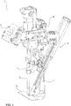
- Figure 1 shows a preferred embodiment of a welding-setting device 1 with an element feed device 3.
- the element feed device 3 is arranged adjacent to the rear part of a C-bracket 5. This reduces the interference contour of the set welding device 1 adjacent to the components B to be connected to one another.
- the setting / welding device 1 preferably comprises a supply unit 7 to which auxiliary welding parts are supplied. From there, the auxiliary welding parts are preferably transferred individually to the element feed device 3, as will be explained in more detail below.
- the set-welding device 1 comprises a known coupling unit 9 for connecting to a robot (not shown).
- the element feed device 3 is preferably connected to the setting / welding device 1 via at least one clamping piece K or shim.
- the clamping piece K forms the basis for connecting the element feed device 3 to setting-welding devices 1 of different types and sizes. In addition, it forms the basis for offering the element feed device 3 as a retrofit kit (see below) and for combining it with existing setting / welding devices 1.
- the set-welding device 1 comprises, in addition to the C-frame, which supports a counter electrode E, an electrode punch S or, in general, a welding electrode.
- the two terms electrode punch S and welding electrode refer to the same part of the set welding device 1. This term is occasionally used differently depending on the setting force to be used for the auxiliary welding part, but is used synonymously here.
- the electrode punch S thus serves as an element for applying a mechanical setting force to the auxiliary welding part and as an electrode for applying an electrical load to the auxiliary welding part.
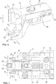
- Figure 2 the setting-welding device 1 is shown again enlarged.
- the element feed device 3 comprises at least one linear drive 10, with a movable end 12 and a fixed end 14.
- the linear drive 10 is a pneumatic cylinder, a hydraulic cylinder or a servomotor or generally any common actuator with which a length change is generated in a targeted manner can be. Via its change in length, the linear drive 10 moves the movable end 12 in a first direction of movement R 10 or in the opposite direction. This is indicated by the arrow R 10 in the Figures 3 and 4th illustrated.
- An element nest 30 is attached to the moving end 12 of the linear drive 10.
- the element nest 30 is used to take over, transport and transfer an individual auxiliary welding joining part 2 at a joint (see below).
- the element nest 30 is preferably guided on a linear guide 16 parallel to the linear drive 10.
- the element nest 30 is preferably attached to a slide 17 which runs on a rail 18.
- the movement of the carriage 17 on the rail 18 can preferably be braked and / or blocked.
- This design of the movement of the element nest 30 with the aid of the linear guide 16 and the slide 17 forms a preferred basis for realizing the functionality of the element feed device 3.
- the element nest 30 described in more detail below is preferably moved with only one linear drive 10 for feeding an auxiliary welding part 2 to the joint.
- this enables the joint and the transfer unit 7 for auxiliary welding parts 2 to be reliably reached.
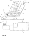
- the element feed device 3 in the preferred configuration with only one linear drive 10 is enlarged in FIG Figure 5 shown.
- the auxiliary welding part 2 is blown to a transfer position via a profile hose 8.
- a preferred locking element prevents the auxiliary welding part 2 from leaving the supply unit 7 in an uncontrolled manner.
- the auxiliary welding joining part 2 is pushed into the element nest 30 with the aid of a plurality of interacting levers and an actuating actuator 6.
- the movable end 12 of the linear drive 10 is preferably connected to the element nest 30 via a mechanical, direction-changing coupling component 20.
- the coupling component 20 is a toggle-like construction which provides a fastening 22, 24, preferably a fastening pin, for the moving end 12 of the linear drive 10 and for the element nest 30.
- the coupling component 20 is preferably formed by a rotatably arranged coupling lever with the plurality of fastening points.
- the fastening pins 22, 24 allow the interconnected components to rotate relative to one another.
- the two fastening pins 22, 24 lie on a common line.
- a further fastening pin 26 is provided on the slide 17 of the linear guide 16. The fastening pin 26 ensures that the coupling component 20 rotates about the fastening 26.
- the coupling component 20 is preferably spring-biased against the moving end 12 of the linear drive 10. This means that only when a threshold force is reached by the moving end 12 of the linear drive 10 during the movement in the first direction of movement R 10 does the coupling component 20 begin to rotate about the fastening 26. In comparison of the Figures 5 and 8th the rotational movement of the coupling component 20 becomes clear. To trigger this rotary movement of the coupling component 20 around the attachment 26, the movement of the slide 17 of the linear guide 16 is preferably blocked. This results in the moving end 12 pressing against the coupling component 20 via the fastening 22 in order to rotate the coupling component 20 about the fastening 26 after the threshold force has been reached.
- the fastening pin 24 is preferably guided in a first elongated hole 29A of a connecting block 28 between the coupling component 20 and the element nest 30, the rotation of the coupling component 20 in the direction of the element nest 30 produces a movement or displacement of the element nest 30 away from the moving end 12 in the direction R 30 (see arrow in Figures 5 and 8th ).
- the movement or displacement of the element nest 30 in the direction R 30 takes place in a second direction of movement, which differs from the first direction of movement R 10 of the linear drive 10. According to the invention, this movement is preferably brought about in the second direction of movement R 30 by the linear drive 10 without an additional drive in the second direction of movement R 30 being required.
- a second elongated hole 29B ensures the direction of movement R 30 of the connecting block 28 and thus of the element nest 30.
- at least one guide pin 32 of the element nest 30 engages in the second elongated hole 29B and only allows movement of the element nest 30 in the direction of the second elongated hole 29B.
- the two directions of movement R 10 and R 30 are preferably characterized in that they are neither parallel nor anti-parallel to one another. Rather, the two directions of movement R 10 and R 30 enclose an angle unequal to 0 ° and unequal to 180 °.
- the slide 17 When the element nest 30 is delivered to the provision unit 7 in the direction R 30 , the slide 17 must be braked in order to trigger the rotation of the coupling component 20 about the fastening 26, in particular a fastening pin or fastening pin.
- the movable end 12 moves of the linear drive 10 in the direction of R 10 .
- the end 12 of the linear drive 10 preferably moves in the opposite direction to the direction R 10 (see FIG Figure 5 ).
- the coupling component 20 rotates around the fastening pin 26 in the opposite direction to R 30 .
- the element nest 30 is moved back into its starting position adjacent to the moving end 12 of the linear drive 10, as shown in FIG Figure 4 is shown.
- the linear drive 10 sets the element nest 30 in the starting position in the direction R 10 to the components B.
- the coupling component 20 is still preferably spring-pretensioned and has not yet been rotated about the fastening pin 26 in the direction of the element nest 30.
- a hold-down device 40 is preferably arranged adjacent to the element nest 30 and upstream of the element nest 30 in the direction R 10.
- the holding-down device 40 is likewise preferably fastened to the slide 17, which is guided by the linear guide 16. Due to the movement of the linear drive 10 in the direction R 10 , the hold-down 40 presses on the components B and blocks further movement of the carriage 17 and the element nest 30 in the direction R 10 .
- the force applied by the hold-down 40 to the components B reduces or eliminates an existing gap between the components B and thus prepares the production of a joint.
- the blocking of the further movement of the carriage 17 by the holding-down device 40 corresponds to the blocking or braking of the carriage 17 on the preparation unit 7 (see above). If the linear actuator 10 also extends after the placing of the blank holder 40 in the direction R 10, ie, the end 12 is moved further in the direction R 10, the linear actuator 10 overcomes the threshold force of the coupling component 20 and starts the rotation of the coupling component 20 about the mounting pin 26th In this way, the element nest 30 is offset in the direction of the joint above a lower electrode E (see FIG Figure 9 ).
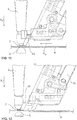
- the hold-down 40 is preferably fork-shaped with two arms 42, 44. Between the arms 42, 44 there is a free space into which the element nest 30 moves the auxiliary welding part 2 via the rotation of the coupling component 20 (see FIG Figures 9 and 7th ).
- the auxiliary welding joining part 2 is clamped to the component 2 by the electrode die S and is thereby held (see Figures 10 and 11 ).
- the linear drive 10 is shortened and the end 12 moves in the opposite direction to the direction R 10 .
- the coupling component 20 is rotated back into its starting position and the element nest 30 is removed from the electrode die S, as is the case in comparison with FIG Figures 11 and 12 can be seen.
- the element nest has a pair of resilient element jaws 33 and a contour piece 34.
- the element jaws 33 are designed to be resilient relative to one another.
- the element jaws 33 preferably consist of a spring plate. Since the element jaws 33 are opposite one another, they form a resilient pliers-like arrangement in order to hold the auxiliary welding joining part 2 between them in a detachable manner.
- the inner sides of the element jaws 33 facing one another have an inner contour that is adapted to the shape of the auxiliary welding part 2.
- the element jaws 30 are mounted in a floating manner in a plane approximately perpendicular to the joining direction R F. Floating means that the element jaws 33 together in the direction R s according to FIG Figure 6 can evade in order to compensate for possible alignment tolerances, for example with respect to the electrode stamp S.
- the contour piece 34 has a contact contour surface 35, which is discussed in more detail below.
- the contour piece 34 is pivotably held in a coupling block 36 via a retaining pin 37.
- the retaining pin 37 runs through a fork-like clearance approximately parallel to the joining direction R F.
- the contour piece 34 with a holding opening is arranged within the fork-like opening.
- the contour piece 34 can pivot about the retaining pin 37 in the plane approximately perpendicular to the joining direction R F (see arrows R S ).
- the pivoting movement of the contour piece is preferably limited by spring leaves 38 arranged on both sides. These are attached to the side of the coupling block 36 by means of pins 39 and protrude as far as the contour piece 34.
- the pins 39 also ensure that the element nest 30 is guided in the elongated hole 29B of the connecting block 28.
- the element jaws 33 are attached to the contour piece 34.
- the element jaws 33 are floatingly mounted in the same way as the contour piece 34.
- Figure 7 shows a preferred embodiment of the element nest 30 in a view opposite to the joining direction R F , that is, from below. It can be seen in this that the coupling block 36 is held in a recess 48 in a spring-pretensioned manner via a spring 46. This arrangement provides a compensating movement of the contour member 34 and the element jaws 33 along the arrow R A in response to a force acting on the contour piece 34.
- the element nest 30 is preferably a floating mount of the welding auxiliary joining part 2 in the plane perpendicular to the joining direction R F provided that a tolerance compensation or an evasion of the auxiliary welding joining part 2 in three directions within this plane is guaranteed.
- the element feed in the setting / welding device 1 can be implemented with shortened cycle times and with less equipment with regard to sensors and drives. Because according to the invention it is preferably possible, with just one linear drive 10, to take over the auxiliary welding joining part 2 at the supply unit 7 and then to reliably feed it to the joint under the electrode punch S. This is because it is precisely this effective delivery that is guaranteed by the only one linear drive 10 and the movement of the element nest 30 in the two different directions of movement R 10 and R 30 via the direction-changing coupling component 20.
- the element nest 30 implements a tolerance-compensating takeover of an auxiliary welding part 2 on the supply unit 7 and / or a tolerance-compensating arrangement or positioning of the auxiliary welding part 2 at the joint under the electrode die S.
- a tolerance-compensating takeover of an auxiliary welding part 2 on the supply unit 7 and / or a tolerance-compensating arrangement or positioning of the auxiliary welding part 2 at the joint under the electrode die S Denn the floating mounting of the holding position of the auxiliary welding part 2 between the element jaws 33 in combination with the contour piece 34 ensure effective approach accuracy to the supply unit 7 and to the electrode punch S.
- auxiliary welding part 2 is initially positioned approximately exactly above the counter electrode E. However, this position is not necessarily sufficiently precise to then carry out the setting-welding process with the electrode punch S. Instead, in a next step, the electrode die S is moved in the joining direction R F into the contour piece 34 and against the contact contour surface 35.
- the auxiliary welding joining part 2 Due to the floating mounting of the contour piece 34 and the auxiliary welding joining part 2 held by the element jaws 33, the auxiliary welding joining part 2 is optimally aligned with the electrode stamp S and with the counter electrode E by the electrode punch S. Subsequently, the auxiliary welding joining part 2 is clamped to the component B by the electrode stamp S, the element nest 30 is removed and the setting-welding process is carried out.
- the electrode stamp is preferably in a position adjacent to component B and thus to the joint.
- the element nest 30 is moved in the direction R 30 towards the electrode die 20 until the contour piece 34 with the contact contour surface 35 rests on the electrode die S. Since the contact contour surface 35 with the side surface or jacket surface of the electrode die S, in particular the radial outer side thereof, moves to a block, the auxiliary welding part 2 is positioned exactly below the electrode die S via the floating support of the contour piece 34.
- the electrode die S then moves in the joining direction R F and clamps the auxiliary welding part 2 on the component B. After the element nest 30 has been removed from the clamped auxiliary welding part 2 (see FIG Figure 12 ), the set-weld process is carried out.
- the present invention also comprises a retrofit kit with an element feed device 3 preferred according to the invention and / or the element nest 30 for existing set-welding devices.
- the present invention likewise comprises a setting / welding device 1 with the element feed device 3 described above, alone or in combination with the element nest 30 or only with the element nest 30.
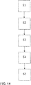
- step Z1 the occupied element nest 30 is fed with the linear movement of the linear drive 10 in the first direction of movement R 10 at least to a joint of the auxiliary welding part 2, the auxiliary welding part 2 being supported by the two oppositely arranged and resilient element jaws 33 of the element nest 30 is held releasably.
- step Z2 the hold-down 40 attached to the linear drive 10 is placed on the at least one component B.
- step Z3 the element nest 30 moves via the mechanical direction-changing coupling component 20 in the second direction of movement R 30 to position the auxiliary welding part 2 at the joint by moving the linear drive 10 further in the first direction of movement R 10 .
- step Z4 the element nest 30 is moved to a stop against the electrode die S, whereby the mechanical stop alignment of the element nest 30 rests laterally on the electrode die S and the auxiliary welding part 2 is held between the element jaws 33 in the joining direction R F and positioned below the electrode die S.
- the auxiliary welding part 2 is clamped by the electrode die S in the joining direction R F against the adjacent component B at the joint, and in the next step Z6, the element nest 33 is removed from the electrode die S. This also results in the auxiliary welding joining part 2 being released from the resilient hold of the element jaws 33.
- the element supply method is used not only to supply the auxiliary welding part 2 to the joint, but also to take over an auxiliary welding part at the supply unit 7. It is therefore preferred in a step Z7 to block a movement of the element nest 30 parallel to the first direction of movement R 10 of the linear drive 10 adjacent to the supply unit or transfer unit 7 for an auxiliary welding part. In this way, the element nest 30 is moved via the mechanical direction-changing coupling component 20 in the second movement direction R 30 in the direction of the provision unit 7. This movement serves to position the element nest 30 on the provision unit 7 by moving the linear drive 10 further in the first direction of movement R 10 .
- step Z8 the element nest 30 is moved against the stop on the provision unit 7.
- the mechanical stop alignment of the element nest, in particular the contour piece 34 with its contact contour surface 35, is moved to a block against the stop 50 of the supply unit 7 and rests there.
- the two element jaws 33 which are resiliently arranged relative to one another, are positioned in a transfer position of the provision unit 7 in order to receive the auxiliary welding part 2.
- step Z9 the auxiliary welding part 2 is moved from the supply unit 7 between the element jaws 33 of the element nest 30, so that the auxiliary welding part 2 is detachably held there.
- the element nest 30 is parallel to the first direction of movement R 10 of the linear drive 10 is moved opposite to the first direction of movement R 10 preferably blocked movement is reset whereby the element nest 30 via the mechanical direction-changing coupling component 20 against the second direction of movement R 30 in a starting position. After this reset has been completed, the occupied element nest 30 is advanced to the joint with the linear movement of the linear drive 10 in the first direction of movement R 10.
- a first step S1 the occupied element nest 30 is fed with the at least one drive 10 to the joint adjacent to the electrode die S, the auxiliary welding part 2 being releasably held by the two oppositely arranged and resilient element jaws 33 of the element nest 30 .
- the element nest 30 is moved to a stop on the electrode die S, whereby the mechanical stop alignment of the element nest 30, i.e. the contour piece 34 with the contact contour surface 35, rests on the side of the electrode die S and the auxiliary welding part is held between the element jaws 33 in the joining direction R.
- F is positioned below the electrode stamp S.
- the element nest 30 with the auxiliary welding joining part 2 held therein is positioned adjacent to the joint, preferably adjacent to the counter electrode E on the component.
- the electrode stamp S is then subsequently moved in the joining direction R F until the contour piece 34 with the contact contour surface 35 rests on the outside of the electrode stamp S.
- the auxiliary welding part 2 is also positioned appropriately under the electrode die S via the floating mounting of the auxiliary welding part 2 in the element nest 30.
- the auxiliary welding part 2 is preferably clamped in step S3 by the electrode die S in the joining direction R F against the adjacent component B at the joint and, in step S4, the element nest 30 is removed from the electrode stamp S and thereby the auxiliary welding part 2 is released from the resilient hold the element jaws 33.
- tolerances are compensated in a supplementary step in a plane approximately perpendicular to the joining direction R F between the electrode die S and the element nest 30 when the element nest 30 is moved to the stop Electrode stamp S with the aid of the floating mounting of the element nest 30 in relation to its attachment to the element feed device.
Priority Applications (6)
| Application Number | Priority Date | Filing Date | Title |
|---|---|---|---|
| EP20154411.1A EP3858532A1 (fr) | 2020-01-29 | 2020-01-29 | Dispositif d'alimentation en élément pour un appareil de placement et de soudage, un réseau d'élément et ensemble de mise à niveau pour le dispositif de placement et de soudage et procédé d'alimentation correspondant d'une pièce d'assemblage auxiliaire par soudage |
| US17/158,273 US11883900B2 (en) | 2020-01-29 | 2021-01-26 | Element supply apparatus for a setting welding device, an element nest and a retrofit kit for the setting welding device as well as corresponding supply methods of a welding auxiliary joining part |
| JP2021011952A JP7229282B2 (ja) | 2020-01-29 | 2021-01-28 | 溶接固定装置のための要素供給装置、要素保持部、及び溶接固定装置のための改装部品、並びに、これらに対応する溶接補助接合部品の供給方法 |
| KR1020210012554A KR102429703B1 (ko) | 2020-01-29 | 2021-01-28 | 세팅 용접 장치를 위한 요소 공급 장치, 세팅 용접 장치를 위한 요소 네스트와 개장 키트, 및 이에 대응하는 용접 보조 결합 부품의 공급 방법 |
| CN202110130669.2A CN113275726B (zh) | 2020-01-29 | 2021-01-29 | 用于定位焊接设备的元件供给装置、元件组和改装套件及相应的焊接辅助连接件的供给方法 |
| US18/541,056 US20240139855A1 (en) | 2020-01-29 | 2023-12-15 | Element supply apparatus for a setting welding device, an element nest and a retrofit kit for the setting welding device as well as corresponding supply methods of a welding auxiliary joining part |
Applications Claiming Priority (1)
| Application Number | Priority Date | Filing Date | Title |
|---|---|---|---|
| EP20154411.1A EP3858532A1 (fr) | 2020-01-29 | 2020-01-29 | Dispositif d'alimentation en élément pour un appareil de placement et de soudage, un réseau d'élément et ensemble de mise à niveau pour le dispositif de placement et de soudage et procédé d'alimentation correspondant d'une pièce d'assemblage auxiliaire par soudage |
Publications (1)
| Publication Number | Publication Date |
|---|---|
| EP3858532A1 true EP3858532A1 (fr) | 2021-08-04 |
Family
ID=69400475
Family Applications (1)
| Application Number | Title | Priority Date | Filing Date |
|---|---|---|---|
| EP20154411.1A Pending EP3858532A1 (fr) | 2020-01-29 | 2020-01-29 | Dispositif d'alimentation en élément pour un appareil de placement et de soudage, un réseau d'élément et ensemble de mise à niveau pour le dispositif de placement et de soudage et procédé d'alimentation correspondant d'une pièce d'assemblage auxiliaire par soudage |
Country Status (5)
| Country | Link |
|---|---|
| US (2) | US11883900B2 (fr) |
| EP (1) | EP3858532A1 (fr) |
| JP (1) | JP7229282B2 (fr) |
| KR (1) | KR102429703B1 (fr) |
| CN (1) | CN113275726B (fr) |
Citations (7)
| Publication number | Priority date | Publication date | Assignee | Title |
|---|---|---|---|---|
| JP2002018650A (ja) * | 2000-06-29 | 2002-01-22 | Seki Kogyo Kk | ボルトフィーダ |
| JP2016107332A (ja) * | 2014-12-08 | 2016-06-20 | 新光機器株式会社 | 溶接ボルトの供給装置 |
| US20170008136A1 (en) * | 2015-07-07 | 2017-01-12 | Dengensha Manufacturing Company Limited | Nut Feeding Apparatus |
| WO2017048912A1 (fr) | 2015-09-16 | 2017-03-23 | Alcoa Inc. | Appareil d'alimentation en rivets |
| EP3199288A2 (fr) | 2016-01-28 | 2017-08-02 | Böllhoff Verbindungstechnik GmbH | Dispositif d'alimentation en éléments d'un appareil de placement et de soudage, appareil de placement et de soudage et procédé d'assemblage sous la forme d'un processus de placement et de soudage mécano-thermique |
| JP6223956B2 (ja) * | 2014-03-03 | 2017-11-01 | 矢島技研株式会社 | 部品供給装置及びそれを用いた抵抗溶接機 |
| DE102017112448A1 (de) | 2017-06-06 | 2018-12-06 | Arnold & Shinjo Gmbh & Co. Kg | Vorrichtung und Verfahren zur Herstellung eines Bauteilverbunds sowie Kraftfahrzeug |
Family Cites Families (6)
| Publication number | Priority date | Publication date | Assignee | Title |
|---|---|---|---|---|
| JP5090071B2 (ja) | 2007-06-12 | 2012-12-05 | 矢島技研株式会社 | 小物部品供給装置 |
| CN201245367Y (zh) | 2008-07-25 | 2009-05-27 | 小原(南京)机电有限公司 | 螺母输送机的惯性输送主轴 |
| JP5251534B2 (ja) | 2009-01-19 | 2013-07-31 | セキ工業株式会社 | 抵抗溶接用ナット供給装置 |
| KR101200541B1 (ko) | 2011-03-23 | 2012-11-13 | 주식회사 조웰 | 너트 자동용접기의 너트 공급장치 |
| RU2601252C1 (ru) * | 2015-07-27 | 2016-10-27 | Ержан КарымгазыУлы Мукенев | Облегчающая стелька для обуви на каблуке |
| WO2019118659A1 (fr) | 2017-12-14 | 2019-06-20 | Arconic Inc. | Systèmes de soudage par rivets par points de résistance et procédés d'utilisation correspondants |
-
2020
- 2020-01-29 EP EP20154411.1A patent/EP3858532A1/fr active Pending
-
2021
- 2021-01-26 US US17/158,273 patent/US11883900B2/en active Active
- 2021-01-28 KR KR1020210012554A patent/KR102429703B1/ko active IP Right Grant
- 2021-01-28 JP JP2021011952A patent/JP7229282B2/ja active Active
- 2021-01-29 CN CN202110130669.2A patent/CN113275726B/zh active Active
-
2023
- 2023-12-15 US US18/541,056 patent/US20240139855A1/en active Pending
Patent Citations (7)
| Publication number | Priority date | Publication date | Assignee | Title |
|---|---|---|---|---|
| JP2002018650A (ja) * | 2000-06-29 | 2002-01-22 | Seki Kogyo Kk | ボルトフィーダ |
| JP6223956B2 (ja) * | 2014-03-03 | 2017-11-01 | 矢島技研株式会社 | 部品供給装置及びそれを用いた抵抗溶接機 |
| JP2016107332A (ja) * | 2014-12-08 | 2016-06-20 | 新光機器株式会社 | 溶接ボルトの供給装置 |
| US20170008136A1 (en) * | 2015-07-07 | 2017-01-12 | Dengensha Manufacturing Company Limited | Nut Feeding Apparatus |
| WO2017048912A1 (fr) | 2015-09-16 | 2017-03-23 | Alcoa Inc. | Appareil d'alimentation en rivets |
| EP3199288A2 (fr) | 2016-01-28 | 2017-08-02 | Böllhoff Verbindungstechnik GmbH | Dispositif d'alimentation en éléments d'un appareil de placement et de soudage, appareil de placement et de soudage et procédé d'assemblage sous la forme d'un processus de placement et de soudage mécano-thermique |
| DE102017112448A1 (de) | 2017-06-06 | 2018-12-06 | Arnold & Shinjo Gmbh & Co. Kg | Vorrichtung und Verfahren zur Herstellung eines Bauteilverbunds sowie Kraftfahrzeug |
Also Published As
| Publication number | Publication date |
|---|---|
| US20240139855A1 (en) | 2024-05-02 |
| CN113275726B (zh) | 2023-02-17 |
| JP7229282B2 (ja) | 2023-02-27 |
| JP2021119015A (ja) | 2021-08-12 |
| US11883900B2 (en) | 2024-01-30 |
| CN113275726A (zh) | 2021-08-20 |
| US20210252631A1 (en) | 2021-08-19 |
| KR20210097053A (ko) | 2021-08-06 |
| KR102429703B1 (ko) | 2022-08-04 |
Similar Documents
| Publication | Publication Date | Title |
|---|---|---|
| DE3319716C2 (de) | Vorrichtung zum zuordnen und verschweissen von seitenteilen zu bzw. mit dach- und bodenteilen eines kraftfahrzeugs | |
| DE102009049616B4 (de) | Setzgerät, Zuführmodul des Setzgeräts und Fügeverfahren zum Verbinden von mindestens zwei Bauteilen | |
| WO2007110236A1 (fr) | Dispositif de serrage pour loger et serrer des éléments | |
| EP3199288B1 (fr) | Dispositif d'alimentation en éléments d'un appareil de placement et de soudage, appareil de placement et de soudage et procédé d'assemblage sous la forme d'un processus de placement et de soudage mécano-thermique | |
| DE112015001669T5 (de) | Spannvorrichtung | |
| EP2694231B1 (fr) | Dispositif de transfert pour une presse ou un train de presses comprenant une transmission et support de base échangeable | |
| EP1871696A1 (fr) | Dispositif de prehension | |
| AT510969B1 (de) | Werkzeughalterung für abkantpresse | |
| AT514821B1 (de) | Biegepresse und Biegeverfahren | |
| EP3180138B1 (fr) | Outil de cintrage et dispositif de préhension servant à manipuler l'outil de cintrage | |
| DE2930006A1 (de) | Werkstueckbeschickungsvorrichtung mit beweglichkeit fuer fluchtausgleich | |
| DE102010017981B4 (de) | Einrichtung und Verfahren zum Zusammenführen von Leitern | |
| EP0226212B1 (fr) | Dispositif et procédé pour le montage par en dessous des groupes de propulsion dans une carrosserie automobile | |
| EP3664959B1 (fr) | Procédé et dispositif de fourniture de vis | |
| EP1117497B1 (fr) | Dispositif d'aboutage, procede d'aboutage par enchevetrement et assemblage realise par aboutage par enchevetrement | |
| DE102006009432B4 (de) | Greifvorrichtung für eine Werkzeugwechselvorrichtung | |
| EP3858532A1 (fr) | Dispositif d'alimentation en élément pour un appareil de placement et de soudage, un réseau d'élément et ensemble de mise à niveau pour le dispositif de placement et de soudage et procédé d'alimentation correspondant d'une pièce d'assemblage auxiliaire par soudage | |
| DE3542451A1 (de) | Handhabungseinrichtung fuer montageteile | |
| DE102006057506A1 (de) | Verfahren zur Korrektur der Seitenposition eines Bedruckstoffes | |
| DE102009003516A1 (de) | Automatische Greiferkopplung | |
| WO2020212055A1 (fr) | Tête de pose, fiche de presse ou dispositif de pose pourvu de cette tête de pose et procédé d'assemblage d'un élément d'assemblage pourvu de la tête de pose | |
| EP4129575B1 (fr) | Dispositif de montage d'anneau, ainsi que procédé de réglage d'un dispositif de montage d'anneau | |
| EP1522374B1 (fr) | Dispositif de transport d'éléments | |
| DE10008489B4 (de) | Verfahren und Vorrichtung zur Zuführung einer Druckplatte | |
| DE2607986C3 (de) | Einspannvorrichtung |
Legal Events
| Date | Code | Title | Description |
|---|---|---|---|
| PUAI | Public reference made under article 153(3) epc to a published international application that has entered the european phase |
Free format text: ORIGINAL CODE: 0009012 |
|
| STAA | Information on the status of an ep patent application or granted ep patent |
Free format text: STATUS: THE APPLICATION HAS BEEN PUBLISHED |
|
| AK | Designated contracting states |
Kind code of ref document: A1 Designated state(s): AL AT BE BG CH CY CZ DE DK EE ES FI FR GB GR HR HU IE IS IT LI LT LU LV MC MK MT NL NO PL PT RO RS SE SI SK SM TR |
|
| STAA | Information on the status of an ep patent application or granted ep patent |
Free format text: STATUS: REQUEST FOR EXAMINATION WAS MADE |
|
| 17P | Request for examination filed |
Effective date: 20210916 |
|
| RBV | Designated contracting states (corrected) |
Designated state(s): AL AT BE BG CH CY CZ DE DK EE ES FI FR GB GR HR HU IE IS IT LI LT LU LV MC MK MT NL NO PL PT RO RS SE SI SK SM TR |
|
| STAA | Information on the status of an ep patent application or granted ep patent |
Free format text: STATUS: EXAMINATION IS IN PROGRESS |
|
| 17Q | First examination report despatched |
Effective date: 20231129 |