EP3664959B1 - Procédé et dispositif de fourniture de vis - Google Patents
Procédé et dispositif de fourniture de vis Download PDFInfo
- Publication number
- EP3664959B1 EP3664959B1 EP18742937.8A EP18742937A EP3664959B1 EP 3664959 B1 EP3664959 B1 EP 3664959B1 EP 18742937 A EP18742937 A EP 18742937A EP 3664959 B1 EP3664959 B1 EP 3664959B1
- Authority
- EP
- European Patent Office
- Prior art keywords
- screw
- magazine
- holder
- screwing
- closed position
- Prior art date
- Legal status (The legal status is an assumption and is not a legal conclusion. Google has not performed a legal analysis and makes no representation as to the accuracy of the status listed.)
- Active
Links
- 238000000034 method Methods 0.000 title claims description 18
- 238000012546 transfer Methods 0.000 claims description 20
- 230000008859 change Effects 0.000 claims description 16
- 230000009471 action Effects 0.000 claims description 7
- 230000007246 mechanism Effects 0.000 claims description 4
- 230000008569 process Effects 0.000 description 4
- 238000004519 manufacturing process Methods 0.000 description 3
- 238000013459 approach Methods 0.000 description 2
- 230000008901 benefit Effects 0.000 description 2
- 238000006073 displacement reaction Methods 0.000 description 2
- 238000012545 processing Methods 0.000 description 2
- 230000032258 transport Effects 0.000 description 2
- 241001136792 Alle Species 0.000 description 1
- 238000010276 construction Methods 0.000 description 1
- 230000001419 dependent effect Effects 0.000 description 1
- 238000013461 design Methods 0.000 description 1
- 238000011161 development Methods 0.000 description 1
- 230000018109 developmental process Effects 0.000 description 1
- 230000000694 effects Effects 0.000 description 1
- 230000005672 electromagnetic field Effects 0.000 description 1
- 230000000149 penetrating effect Effects 0.000 description 1
- 229910001285 shape-memory alloy Inorganic materials 0.000 description 1
Images

Classifications
-
- B—PERFORMING OPERATIONS; TRANSPORTING
- B23—MACHINE TOOLS; METAL-WORKING NOT OTHERWISE PROVIDED FOR
- B23P—METAL-WORKING NOT OTHERWISE PROVIDED FOR; COMBINED OPERATIONS; UNIVERSAL MACHINE TOOLS
- B23P19/00—Machines for simply fitting together or separating metal parts or objects, or metal and non-metal parts, whether or not involving some deformation; Tools or devices therefor so far as not provided for in other classes
- B23P19/001—Article feeders for assembling machines
-
- B—PERFORMING OPERATIONS; TRANSPORTING
- B23—MACHINE TOOLS; METAL-WORKING NOT OTHERWISE PROVIDED FOR
- B23P—METAL-WORKING NOT OTHERWISE PROVIDED FOR; COMBINED OPERATIONS; UNIVERSAL MACHINE TOOLS
- B23P19/00—Machines for simply fitting together or separating metal parts or objects, or metal and non-metal parts, whether or not involving some deformation; Tools or devices therefor so far as not provided for in other classes
- B23P19/04—Machines for simply fitting together or separating metal parts or objects, or metal and non-metal parts, whether or not involving some deformation; Tools or devices therefor so far as not provided for in other classes for assembling or disassembling parts
- B23P19/06—Screw or nut setting or loosening machines
-
- B—PERFORMING OPERATIONS; TRANSPORTING
- B23—MACHINE TOOLS; METAL-WORKING NOT OTHERWISE PROVIDED FOR
- B23Q—DETAILS, COMPONENTS, OR ACCESSORIES FOR MACHINE TOOLS, e.g. ARRANGEMENTS FOR COPYING OR CONTROLLING; MACHINE TOOLS IN GENERAL CHARACTERISED BY THE CONSTRUCTION OF PARTICULAR DETAILS OR COMPONENTS; COMBINATIONS OR ASSOCIATIONS OF METAL-WORKING MACHINES, NOT DIRECTED TO A PARTICULAR RESULT
- B23Q7/00—Arrangements for handling work specially combined with or arranged in, or specially adapted for use in connection with, machine tools, e.g. for conveying, loading, positioning, discharging, sorting
- B23Q7/10—Arrangements for handling work specially combined with or arranged in, or specially adapted for use in connection with, machine tools, e.g. for conveying, loading, positioning, discharging, sorting by means of magazines
-
- B—PERFORMING OPERATIONS; TRANSPORTING
- B23—MACHINE TOOLS; METAL-WORKING NOT OTHERWISE PROVIDED FOR
- B23P—METAL-WORKING NOT OTHERWISE PROVIDED FOR; COMBINED OPERATIONS; UNIVERSAL MACHINE TOOLS
- B23P2700/00—Indexing scheme relating to the articles being treated, e.g. manufactured, repaired, assembled, connected or other operations covered in the subgroups
- B23P2700/50—Other automobile vehicle parts, i.e. manufactured in assembly lines
Definitions
- the invention relates to methods and devices for providing connecting elements such as screws or the like, in particular on automated screwing systems such as are used in the automotive industry, for example.
- EP 2 010 356 B1 describes a screwing system in which several screwing tools are combined in two groups, with only the screwing tools of one of the two groups being required for a screwing process, and proposes driving one screwing tool from each group by a common drive device in order to reduce the number of required to keep drive devices low.
- DE 10 2012 224 045 A1 discloses a screwing system in which screws are not inserted at the screwing points during pre-assembly, but are fed individually to the screwdriver via an automatic feed device.
- DE 102 26 164 A1 discloses a magazine in which a belt-like screw holder having a plurality of linearly arranged clamping devices for receiving screws is inserted into a magazine well.
- DE 10 2009 040 764 A1 discloses a magazine with which a plurality of connecting elements can be fed to a processing device and which has the following features: a plurality of holding positions spaced apart from one another, at each of which a connecting element can be detachably held, while the holding positions of the magazine can be refilled and the magazine on the processing device can be attached interchangeably.
- the DE 10 2009 040 764 A1 discloses the features of the preamble of claim 1.
- the arm does not have all the drive and supply devices that are required to operate complicated tools, but these tools are in turn combined with the entire drive and a part of the robot intelligence to their own tool heads.
- the tool heads Preferably, at least some of the tool heads have magazines that bring components to be assembled and thus make it unnecessary for the robot arm to pivot over large distances to grip a new component.
- a tool head for Screwing a stud into a threaded hole and another tool head for screwing a nut onto a threaded bolt are preferred.
- U.S. 2005 036 850 A1 describes a magazine strip for fasteners, comprising a strip-shaped carrying strap, a plurality of equally spaced transport recesses for stepwise displacement of the magazine strip in a magazine receptacle and an opening towards a first of opposite longitudinal edges of the belt, and a plurality of essentially cylindrical receptacles for holding fasteners defined by a bottom surface and a top surface of the strap and opening to a second of the opposite longitudinal edges of the strap.
- the screw tightening device disclosed includes a magazine plate having a through hole formed in a first direction, a torsion bar device configured to rotate a rotary member having a tip portion, a servomotor that moves the magazine plate in a second direction, a cylinder device that rotates the torsion bar device in moves the first direction, and a screw tightening control unit that controls the servo motor so that the tip portion of the torsion bar device is coaxial with the through hole, and controls the cylinder device so that the tip portion of the rotary member is passed through the through hole and to the head of the bolt.
- An object of the invention is methods and To specify devices for providing connecting elements such as screws or the like, in particular on automated screwing systems, which use a changing magazine for connecting elements such as screws and the like and allow the execution of several screw connections in a short time.
- the change magazine can hold a plurality of screws without energy.
- the interchangeable magazine can be interactively connected to a screw system for dispensing a screw.
- the interchangeable magazine can be exchangeable in order to be able to quickly and easily replace an empty interchangeable magazine with another, previously equipped interchangeable magazine.
- the interchangeable magazine can be adaptable to different screw sizes and/or numbers of screws.
- a screwing system can carry out a large number of screwing operations using the proposed interchangeable magazine with a small number of screwing spindles.
- the system can be easily, quickly and flexibly adapted to changing screw points and screw sizes.
- a device for providing screws in particular on automated screwing systems, which comprises an interchangeable magazine with a plurality of screw holders, each of which has a closed position for frictionally holding a screw and an open position for releasing the screw, the screw holder without feeding of energy remains in its open position.
- a proposed interchangeable magazine has a plurality of screw holders which are each designed to hold one screw and which, as long as no external energy is supplied, hold the respective screw in place. If, on the other hand, energy is supplied to a screw holder from the outside, the screw holder releases the screw, so that the screw can be taken over by a screwing tool, for example, in order to carry out a screw connection. Since the screw holder does not require any energy to hold the screw, a change magazine of the proposed type loaded with screws can be transported without energy supply, for example from a loading station in which the screws were inserted into the screw holders, to the place of use, for example a workstation on an assembly line , whereby the screws cannot be lost and are each held in a defined position.
- open position and “Closed position” makes it clear that the screw holder has at least one movable part which, in the closed position, exerts a force on the inserted screw, so that the screw is held in a predetermined position with a non-positive fit.
- the screw holders are arranged at a distance from one another along a straight arrangement line.
- the interchangeable magazine can be designed to accommodate a very large number of screws. If the screws are to be removed one after the other from such an interchangeable magazine, this can be moved step by step in a simple linear movement such that all screw holders are moved one after the other to a transfer position in which the screw held in the screw holder is released and taken over by a screwing tool can.
- the screw holders are arranged at a distance from one another along a non-straight, for example circular, arrangement line.
- the interchangeable magazine can be designed to be relatively space-saving. If the screws are to be removed one after the other from such an interchangeable magazine, this can be moved step by step in a simple rotational movement, for example, so that all screw holders are moved one after the other to a transfer position in which the screw held in the screw holder can be released and taken over by a screwing tool .
- the screw holder can, for example, at least one have a movable holding element which exerts a transverse force on the screw in the closed position.
- a transverse force means a force that acts perpendicularly to a longitudinal axis of the screw, ie the screw is held by its shank.
- the holding element can, for example, comprise at least one pivotable pivoted lever.
- This pivoted lever can be held in the closed position, i.e. pressed towards the screw, by its own weight, alternatively or additionally by the force of a first spring, or it can be held in the open position by the force of the first spring.
- a first locking mechanism can be arranged in such a way that the pivoted lever is held securely in the closed position, in particular when the pivoted lever is held in the closed position only by its own weight or against the force of the first spring.
- Pivoted levers have a simple mechanical design, are therefore inexpensive to manufacture, robust and functionally reliable.
- the holding element can comprise at least one displaceable clamping jaw.
- This clamping jaw can, for example, be held in the closed position by its own weight, alternatively or additionally by the force of a second spring, ie pressed towards the screw, or by the force of the second spring in the open position.
- a second locking mechanism can be arranged in such a way that the clamping jaw is held securely in the closed position, in particular when the clamping jaw is held in the closed position only by its own weight or against the force of the second spring. Clamping jaws are also mechanically simple structure, therefore inexpensive to manufacture, robust and functionally reliable.
- the holding element advantageously comprises a combination of at least one pivoting lever and at least one clamping jaw.
- the pivoting lever can be attached to the interchangeable magazine so that it can pivot against the force of a first spring
- the clamping jaw can be attached to the free end of the pivoting lever so that it can be displaced against the force of a second spring on the pivoting lever.
- the pivoting lever is pressed either towards or away from the screw by the first spring, and the clamping jaw can hold screws of different diameters in the closed position of the pivoting lever because their relative mobility allows compensation for the different diameters.
- the pivotability of the pivoted lever “against the force of a first spring” can mean that the first spring presses the pivoted lever into the closed position without an external supply of energy and movement into the open position is only possible by an external force counteracting the spring force. However, it can also mean that the first spring presses the pivoting lever into the open position without an external supply of energy and movement into the closed position is only possible by an external force counteracting the spring force. The same applies accordingly to the displaceability of the clamping jaw with regard to the second spring.
- the interchangeable magazine can be attached to a magazine holder arranged in the working area of at least one screwing tool of a screwing system.
- the interchangeable magazine is movably mounted relative to the magazine holder.
- the magazine holder can, for example, be an independent assembly that is installed in a stationary manner and that is approached by a screwing tool in order to take over a new screw between two screwing processes.
- it can also be part of a screwing system in which one or more screwing tools can be moved in space or in a plane, for example, in order to remove screws from the interchangeable magazine on the one hand and to approach different screwing points at which screwing is to be carried out on the other.
- the interchangeable magazine In order to enable a movable arrangement of the interchangeable magazine on the magazine holder, provision can be made, for example, for the interchangeable magazine to have at least one first guide rail which can be combined with a second guide rail arranged on the magazine holder to form a linear guide.
- a linear guide should not necessarily be understood to mean a straight linear guide.
- the screw holders are arranged in a circle, for example, as already described above, it makes sense that the guide rails are also circular.
- other bearing types for example a rotary bearing arranged in the center of the circle, can also be advantageous be provided.
- a drive device can be arranged on the magazine holder, for example, which, when the interchangeable magazine is attached to the magazine holder, is operatively connected to the interchangeable magazine in order to move the interchangeable magazine relative to the magazine holder.
- a drive device can be arranged on the interchangeable magazine, which, when the interchangeable magazine is attached to the magazine holder, is operatively connected to the magazine holder in order to move the interchangeable magazine relative to the magazine holder.
- the first-mentioned configuration is preferred, because the interchangeable magazine can do without its own energy supply.
- the drive device can be designed, for example, as a servomotor with a pinion, which engages in a toothed rack arranged on the interchangeable magazine and thereby moves the interchangeable magazine relative to the magazine holder.
- the drive device for moving the interchangeable magazine relative to the magazine holder is designed in such a way that the screw holders are moved one after the other to a transfer position.
- a transfer position is to be understood as meaning a position that is stationary relative to the magazine holder, at which a screwing tool can be arranged or which can be approached by a screwing tool, and at which the held screw is released and transferred to a screwing tool by the screwing tool in the direction of the longitudinal axis of the screw on the screw head is moved and grabs the screw head.
- each screw holder can have an opening device which is designed to open the screw holder To bring energy supply from the closed position to the open position.
- the supply of different forms of energy is conceivable and should be included in the idea of the invention.
- the energy can be supplied by the screw holder being opened by the action of an external force.
- the opening device can be actuated, for example, by the action of an opening element that does not belong to the interchangeable magazine.
- an opening element can be arranged, for example, on the magazine holder or on a screwing tool of a screwing system.
- the opening element is arranged on a screwing tool of a screwing system, after the screwing tool has gripped the screw, this can actuate the opening device of the screw holder so that it is moved into the open position and releases the held screw.
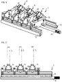
- the removable magazine 1 which is in the Figures 1 to 4 is shown in different views, comprises a plurality of screw holders 11, which are arranged on a straight line of arrangement spaced from each other.
- An opening device 12 is arranged between each two screw holders 11, so that each screw holder 11 is assigned an opening device 12, which allows the automated movement of the screw holder from a closed position, in which a screw S is held, into an open position, in which the screw S is released becomes, serves.
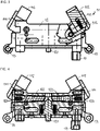
- Each screw holder 11 comprises two pivoting levers 111 which can be pivoted towards one another and which are each held in the open position by the action of a first spring (not shown here) and can be moved into the closed position against the force of this first spring.
- a clamping jaw 112 is mounted so as to be displaceable against the action of a second spring 113 .
- the pivot lever 111 are in the The closed position can be locked and the spring-loaded mounting of the clamping jaws 112 ensures that a screw holder can hold 11 screws S of different diameters.
- the opening device 12 is responsible both for locking the pivoted lever 111 in the closed position and for releasing the pivoted lever 111 from the closed position into the open position. It comprises two locking bolts 122 which can be displaced outwards in the horizontal direction against the force of a third spring 123 each. An actuating bolt 121 can be displaced vertically so that it causes horizontal outward movement of the two locking bolts 122, whereby the two pivoting levers 111 are unlocked and then pivoted outwards from the closed position to the open position, i.e. away from the screw S.
- the outward movement of the locking bolts 122 releases the locking of the pivoting lever 111 in the closed position.
- the two locking bolts 122 are locked in their outward position, ie the locking bolt 122 is held in this position against the force of the third spring 123 .
- the pivoted levers 111 released by the unlocking move from the closed position into the open position by the force of the two first springs (not shown here). If the pivoting levers 111 are moved from the open position to the closed position against the force of the first springs when the interchangeable magazine is loaded with screws S, they are locked therein, while at the same time the locking bolts 122 are unlocked and locked again by the force of the third springs 123 into the inland position to be moved back.
- the alternating arrangement of screw holders 11 and opening devices 12 is held together by two laterally arranged rails, on each of which a first guide rail 13 is arranged.
- the interchangeable magazine 1 has a toothed rack 14 .
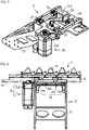
- the magazine holder 2 in the Figures 5 to 8 shown in various views, comprises a basic structure 21 with an opening element, which in the specific exemplary embodiment consists of a pin 221 that is attached to a base plate 222 and two short-stroke cylinders 223 that can move the base plate 222 up and down with the pin 221 .
- Two second guide rails 23 are also attached to the basic framework, into which the interchangeable magazine 1 with its first guide rails 13 can be inserted.
- the two second guide rails 23 are segmented, i.e. two short, collinearly arranged rail segments form a second guide rail 23 which, as a fixed bearing of a linear guide, accommodates a first guide rail 13 of the interchangeable magazine 1 as a movable bearing of the linear guide.
- a drive device 24 is attached to the base structure 21 , which in the specific exemplary embodiment comprises a servomotor 241 and a pinion 242 attached to the motor shaft of the servomotor 241 .
- the interchangeable magazine can be displaced along the linear guide formed thereby relative to the magazine holder.
- the drive device 24 can effect a step-by-step displacement of the interchangeable magazine 1 along the linear guide, so that all the screw holders 11 are gradually moved into a transfer position. at which the screw held in the respective screw holder 11 can be taken over by a screwing tool.
- this transfer position is at the point shown in 8 is marked by the visible there recess of the base plate 222 of the opening element 22.
- this recess serves to enable the screwing tool arranged underneath to reach through after it has removed the screw S from the screw holder 11 currently located at this transfer position.
- the interchangeable magazine 1 itself is in 8 not shown; out 6 However, it can be seen that the middle one of the five screw holders shown there is currently at the transfer position.
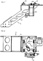
- the screwing tool 3 itself is neither in 8 still in 6 shown; in 9 however, an exemplary application is shown in which all of the components described so far interact as described below. It should be noted, however, that the exchangeable magazine described in all its aspects can be used advantageously on any screwing system, ie for example, a 6-axis industrial robot or the like, can be used advantageously.
- two linear guides 31, 32 are arranged perpendicular to one another such that the two screwing tools 3 can be moved to any point in the horizontal plane in order to be able to screw screwing points arranged above the screwing system.
- a magazine holder 2 Fixed to the screwing tool 3 arranged on the left in the selected illustration is a magazine holder 2 which is therefore moved in the horizontal plane with the screwing tool 3 .
- an interchangeable magazine 1 On the magazine holder 2 there is an interchangeable magazine 1 which can be displaced step by step relative to the magazine holder 2 and thus relative to the screwing tool 3 such that each screw holder 11 can be moved into the transfer position.
- the transfer position is in 9 to be recognized by the screw spindle of the screwing tool 3 penetrating the interchangeable magazine 1 from bottom to top.
- the screwing tool 3 arranged below the transfer position is adjustable in length. First, the screwing tool 3 approaches the screw head of the screw S from below until a socket wrench arranged at the end of the screw spindle grips the screw head.
- the short-stroke cylinders 223 then raise the base plate 222 with the pin 221 of the opening element 22, whereby the pin 221 acts on the actuating pin 121 of the opening device 12 associated with the screw holder 11 which is currently at the transfer position.
- the screw spindle of the screwdriver 3 with the screw S can be moved upwards through the interchangeable magazine 1 to the screwing point and carry out the screwing process.
Claims (16)
- Dispositif pour la fourniture de vis (S), notamment sur des systèmes de vissage automatisés, comprenant un magasin de rechange (1) avec une pluralité de supports de vis (11), qui présentent chacun une position de fermeture pour le maintien par force de respectivement une vis (S) et une position d'ouverture pour la libération de la vis (S), caractérisé en ce que le support de vis (11) reste dans sa position d'ouverture sans apport d'énergie.
- Dispositif selon la revendication 1, dans lequel les supports de vis (11) sont agencés espacés les uns des autres le long d'une ligne d'agencement rectiligne.
- Dispositif selon la revendication 1 ou 2, dans lequel le support de vis (11) présente au moins un élément de retenue mobile qui exerce une force transversale sur la vis (S) dans la position de fermeture.
- Dispositif selon la revendication 3, dans lequel l'élément de retenue comprend un levier de pivotement pivotant (111) qui est maintenu dans la position de fermeture par son propre poids ou/et par la force d'un premier ressort ou/et par un premier mécanisme d'encliquetage.
- Dispositif selon la revendication 3 ou 4, dans lequel l'élément de retenue comprend une mâchoire de serrage coulissante (112) qui est maintenue dans la position de fermeture par son propre poids ou/et par la force d'un deuxième ressort (113) ou/et par un deuxième mécanisme d'encliquetage.
- Dispositif selon l'une quelconque des revendications 1 à 5, dans lequel le magasin de rechange (1) peut être monté de manière mobile sur un support de magasin (2) agencé dans la zone de travail d'au moins un outil de vissage (3) d'un système de vissage.
- Dispositif selon la revendication 6, dans lequel le magasin de rechange (1) présente au moins un premier rail de guidage (13), qui peut être assemblé avec un deuxième rail de guidage (23) agencé sur le support de magasin (2) pour former un guide linéaire.
- Dispositif selon la revendication 6 ou 7, dans lequel un appareil d'entraînement (24) est agencé sur le support de magasin (2), lequel, lorsque le magasin de rechange (1) est monté sur le support de magasin (2), est relié de manière opérationnelle au magasin de rechange (1) pour déplacer le magasin de rechange (1) par rapport au support de magasin (2).
- Appareil selon la revendication 8, dans lequel l'appareil d'entraînement (24) pour déplacer le magasin de rechange (1) par rapport au support de magasin (2) est configuré pour déplacer les supports de vis (11) les uns après les autres vers une position de transfert.
- Dispositif selon l'une quelconque des revendications 1 à 8, dans lequel chaque support de vis (11) présente un appareil d'ouverture (12) qui est configuré pour amener le support de vis (11) de la position de fermeture à la position d'ouverture lors d'un apport d'énergie.
- Dispositif selon la revendication 10, dans lequel l'appareil d'ouverture (12) est actionné par l'action d'un élément d'ouverture (22).
- Dispositif selon la revendication 11, dans lequel l'élément d'ouverture (22) est agencé sur le support de magasin (2) ou sur un outil de vissage (3) d'un système de vissage.
- Procédé de fourniture de vis (S), notamment sur des systèmes de vissage automatisés, comprenant les étapes suivantes :- la garniture d'un magasin de rechange (1) avec une pluralité de vis (S) par le fait queo au moins un support de vis (11) du magasin de rechange (1) est ouvert,o une ou respectivement une vis (S) est insérée dans le ou respectivement un support de vis (11) ouvert du magasin de rechange (1), eto l'au moins un support de vis (11) ouvert est fermé, et- le déplacement du magasin de rechange (1) garni dans une zone de travail d'au moins un outil de vissage (3) d'un système de vissage.
- Procédé selon la revendication 13, comprenant en outre- le montage mobile du magasin de rechange (1) sur un support de magasin (2) agencé dans la zone de travail d'au moins un outil de vissage (3) d'un système de vissage.
- Procédé selon la revendication 14, comprenant en outre- le déplacement graduel du magasin de rechange (1) de telle sorte que tous les supports de vis (11) sont déplacés les uns après les autres dans une position de transfert définie.
- Procédé selon l'une quelconque des revendications 13 à 15, comprenant en outre- le prélèvement d'au moins une vis (S) du magasin de rechange (1) par au moins un outil de vissage (3), par le fait queo la vis (S) est saisie par l'outil de vissage (3),o le support de vis (11) est déplacé de la position de fermeture à la position d'ouverture, eto l'outil de vissage (3) prélève la vis (S) du support de vis (11).
Applications Claiming Priority (2)
| Application Number | Priority Date | Filing Date | Title |
|---|---|---|---|
| DE102017117961.5A DE102017117961B4 (de) | 2017-08-08 | 2017-08-08 | Verfahren und Vorrichtung zur Bereitstellung von Schrauben |
| PCT/EP2018/067223 WO2019029898A1 (fr) | 2017-08-08 | 2018-06-27 | Procédé et dispositif de fourniture de vis |
Publications (2)
| Publication Number | Publication Date |
|---|---|
| EP3664959A1 EP3664959A1 (fr) | 2020-06-17 |
| EP3664959B1 true EP3664959B1 (fr) | 2022-10-26 |
Family
ID=62976010
Family Applications (1)
| Application Number | Title | Priority Date | Filing Date |
|---|---|---|---|
| EP18742937.8A Active EP3664959B1 (fr) | 2017-08-08 | 2018-06-27 | Procédé et dispositif de fourniture de vis |
Country Status (7)
| Country | Link |
|---|---|
| US (1) | US11253959B2 (fr) |
| EP (1) | EP3664959B1 (fr) |
| CN (1) | CN110997224B (fr) |
| DE (1) | DE102017117961B4 (fr) |
| MX (1) | MX2020001206A (fr) |
| RU (1) | RU2744616C1 (fr) |
| WO (1) | WO2019029898A1 (fr) |
Families Citing this family (3)
| Publication number | Priority date | Publication date | Assignee | Title |
|---|---|---|---|---|
| CN114589525A (zh) * | 2022-03-17 | 2022-06-07 | 周宇航 | 一种工装夹具 |
| CN115091183A (zh) * | 2022-07-15 | 2022-09-23 | 芜湖翡叶动力科技有限公司 | 螺钉同步连接装置及应用该装置的伺服电机接线盒安装机 |
| CN115464383B (zh) * | 2022-09-13 | 2023-11-14 | 中国第一汽车股份有限公司 | 一种自动送钉、拧紧装置及方法 |
Family Cites Families (24)
| Publication number | Priority date | Publication date | Assignee | Title |
|---|---|---|---|---|
| SU814710A1 (ru) * | 1976-10-18 | 1981-03-23 | Проектно-Конструкторский И Тех-Нологический Институт | Устройство дл подачи крепежныхдЕТАлЕй |
| DE3112520A1 (de) * | 1981-03-30 | 1982-10-14 | ARO GmbH, 7024 Filderstadt | Vorrichtung zum einsetzen von schrauben, gewindestiften, nieten, naegeln od.dgl. |
| SU1153467A1 (ru) * | 1983-09-28 | 1987-03-30 | Предприятие П/Я Р-6816 | Схват |
| DE3530230A1 (de) * | 1985-08-23 | 1987-03-05 | Liebherr Verzahntech Gmbh | Fertigungs- und montageeinrichtung |
| SU1425084A1 (ru) * | 1985-12-24 | 1988-09-23 | Всесоюзный Проектно-Конструкторский Институт Технологии Электротехнического Производства | Захватное устройство |
| SU1313699A1 (ru) * | 1985-12-27 | 1987-05-30 | Е. Н. Шапкин | Схват манипул тора |
| DE10162635B4 (de) | 2001-12-20 | 2012-10-04 | Hilti Aktiengesellschaft | Bandförmiges Schraubenmagazin |
| US6814231B2 (en) * | 2002-01-23 | 2004-11-09 | Illinois Tool Works Inc. | Strip of collated fasteners for fastener-driving tool |
| DE10226164A1 (de) | 2002-06-12 | 2003-10-23 | Kuhnke Gmbh Kg H | Schraubenmagazin |
| FR2850895B1 (fr) * | 2003-02-10 | 2006-03-03 | Prospection & Inventions | Bande d'elements de fixation pour appareil de scellement avec chargeur destine a recevoir la bande, l'appareil et le chargeur |
| DE10336872B3 (de) * | 2003-08-11 | 2005-05-04 | Hilti Ag | Magazinstreifen |
| DE102006017653A1 (de) | 2006-04-12 | 2007-10-18 | Robert Bosch Gmbh | Schraubsystem mit variabel zustellbaren Schraubspindeln |
| DE102009016372A1 (de) | 2009-04-07 | 2010-10-21 | Dürr Assembly Products GmbH | Vorrichtung und Verfahren zum automatischen Verbinden zweier Werkstücke |
| DE102009040764B4 (de) * | 2009-09-09 | 2017-08-24 | Böllhoff Verbindungstechnik GmbH | Magazin, Ladestation und Verarbeitungsgerät für Verbindungselemente sowie ein Zufuhrverfahren von Verbindungselementen zum Verarbeitungsgerät und zum Magazin |
| CN202192588U (zh) * | 2011-08-28 | 2012-04-18 | 曹文渊 | 一种螺丝输送装置 |
| CN202910554U (zh) * | 2012-07-31 | 2013-05-01 | 欧姆龙(上海)有限公司 | 自动供给装置 |
| DE102012224045A1 (de) | 2012-12-20 | 2014-06-26 | Weber Schraubautomaten Gmbh | Schraubsystem |
| TWI526275B (zh) | 2013-09-17 | 2016-03-21 | 財團法人工業技術研究院 | 盤匣式螺絲取放裝置 |
| CN103753473B (zh) * | 2013-10-23 | 2016-01-27 | 舟山市派德龙科技有限公司 | 用于调整螺丝匣位置的调节装置 |
| CN103586822A (zh) * | 2013-10-23 | 2014-02-19 | 舟山市派德龙科技有限公司 | 用以自动螺丝批中移动螺钉的施力装置 |
| CN104723054B (zh) * | 2013-12-19 | 2017-05-10 | 致伸科技股份有限公司 | 弹匣式螺丝锁固装置及螺丝补充装置 |
| JP6333661B2 (ja) * | 2014-08-04 | 2018-05-30 | ファナック株式会社 | ねじ締め装置 |
| CN106425964B (zh) * | 2016-09-30 | 2018-01-19 | 国网山东省电力公司商河县供电公司 | 一种带有储钉盒的适用于全材质螺钉的螺丝刀 |
| DE102018103674A1 (de) * | 2018-02-19 | 2019-08-22 | Ejot Gmbh & Co. Kg | Vorrichtung für die Verarbeitung von Elementen |
-
2017
- 2017-08-08 DE DE102017117961.5A patent/DE102017117961B4/de active Active
-
2018
- 2018-06-27 RU RU2020108071A patent/RU2744616C1/ru active
- 2018-06-27 MX MX2020001206A patent/MX2020001206A/es unknown
- 2018-06-27 US US16/633,844 patent/US11253959B2/en active Active
- 2018-06-27 EP EP18742937.8A patent/EP3664959B1/fr active Active
- 2018-06-27 WO PCT/EP2018/067223 patent/WO2019029898A1/fr unknown
- 2018-06-27 CN CN201880050922.XA patent/CN110997224B/zh active Active
Also Published As
| Publication number | Publication date |
|---|---|
| RU2744616C1 (ru) | 2021-03-11 |
| CN110997224B (zh) | 2022-03-22 |
| MX2020001206A (es) | 2020-09-03 |
| DE102017117961B4 (de) | 2023-04-27 |
| EP3664959A1 (fr) | 2020-06-17 |
| US20200206852A1 (en) | 2020-07-02 |
| DE102017117961A1 (de) | 2019-02-14 |
| US11253959B2 (en) | 2022-02-22 |
| CN110997224A (zh) | 2020-04-10 |
| WO2019029898A1 (fr) | 2019-02-14 |
Similar Documents
| Publication | Publication Date | Title |
|---|---|---|
| DE3320762C2 (de) | Stanzmaschine mit einem stationären Magazin | |
| DE602004010978T2 (de) | Handhabungsroboter mit Greifer zur Handhabung von Werkstücken mit unterschiedlichen Formen | |
| EP2498928B1 (fr) | Installation d'usinage, notamment pour le formage libre avec un manipulateur de pièce et d'outil intégré | |
| EP3093080B1 (fr) | Dispositif de changement de matrice comprenant une matrice interchangeable et dome de matrice adaptés et procédé destiné au retrait et à l'insertion de la matrice interchangeable | |
| EP3600798B1 (fr) | Système de préhension et de positionnement servant au transport d'un dispositif de serrage entre différentes positions | |
| DE19832884C1 (de) | Preßzange mit einem Zangenkopf und einem Positionierer | |
| DE3531160A1 (de) | Werkzeugwechsler fuer eine werkzeugmaschine | |
| EP3664959B1 (fr) | Procédé et dispositif de fourniture de vis | |
| AT390908B (de) | Verfahren und vorrichtung zum zufuehren von montageteilen | |
| DE4201289C2 (de) | Vorrichtung zur Handhabung von Werkstücken | |
| DE102014210401A1 (de) | Stopfensetzwerkzeug | |
| WO1997046339A1 (fr) | Machine d'usinage pour pieces sous forme de plaques, notamment pour produire des bords plies sur des pieces en tole | |
| DE3715140A1 (de) | Handhabungseinrichtung | |
| DE3519754C2 (fr) | ||
| EP2554326A1 (fr) | Machine-outil avec un magazine pour outils et un échangeur d'outils articulé | |
| AT515407B1 (de) | Biegewerkzeug sowie Wechseleinheit hierfür | |
| EP1289711B1 (fr) | Dispositif de prehension et de transport de pieces dans des machines rotatives | |
| DE3532667C2 (fr) | ||
| EP0426798A1 (fr) | Dispositif de manipulation d'objets et son application. | |
| EP3031572A1 (fr) | Dispositif de changement d'outil destine a etre utilise dans un centre d'usinage et centre d'usinage destine a l'usinage mecanique d'une piece a usiner | |
| DE102016102940B4 (de) | Verfahren und Bearbeitungseinrichtung zum Bearbeiten, insbesondere zum Umformen von länglichen Materialabschnitten, und Spanneinheit zur Durchführung des Verfahrens | |
| EP0143257A1 (fr) | Raccordement d'outil d'une presse de découpage, notamment d'une presse de découpage à plateau revolver, pour le changement d'outil | |
| DE2819607C2 (de) | Magazin zum Speichern von mit Werkzeugen bestückten Werkzeughaltern für Werkzeugmaschinen | |
| CH680992A5 (fr) | ||
| WO2023247056A1 (fr) | Procédé et appareil de positionnement d'une pièce à usiner entre deux étaux |
Legal Events
| Date | Code | Title | Description |
|---|---|---|---|
| STAA | Information on the status of an ep patent application or granted ep patent |
Free format text: STATUS: UNKNOWN |
|
| STAA | Information on the status of an ep patent application or granted ep patent |
Free format text: STATUS: THE INTERNATIONAL PUBLICATION HAS BEEN MADE |
|
| PUAI | Public reference made under article 153(3) epc to a published international application that has entered the european phase |
Free format text: ORIGINAL CODE: 0009012 |
|
| STAA | Information on the status of an ep patent application or granted ep patent |
Free format text: STATUS: REQUEST FOR EXAMINATION WAS MADE |
|
| 17P | Request for examination filed |
Effective date: 20200129 |
|
| AK | Designated contracting states |
Kind code of ref document: A1 Designated state(s): AL AT BE BG CH CY CZ DE DK EE ES FI FR GB GR HR HU IE IS IT LI LT LU LV MC MK MT NL NO PL PT RO RS SE SI SK SM TR |
|
| AX | Request for extension of the european patent |
Extension state: BA ME |
|
| DAV | Request for validation of the european patent (deleted) | ||
| DAX | Request for extension of the european patent (deleted) | ||
| GRAP | Despatch of communication of intention to grant a patent |
Free format text: ORIGINAL CODE: EPIDOSNIGR1 |
|
| STAA | Information on the status of an ep patent application or granted ep patent |
Free format text: STATUS: GRANT OF PATENT IS INTENDED |
|
| INTG | Intention to grant announced |
Effective date: 20220510 |
|
| GRAS | Grant fee paid |
Free format text: ORIGINAL CODE: EPIDOSNIGR3 |
|
| GRAA | (expected) grant |
Free format text: ORIGINAL CODE: 0009210 |
|
| STAA | Information on the status of an ep patent application or granted ep patent |
Free format text: STATUS: THE PATENT HAS BEEN GRANTED |
|
| AK | Designated contracting states |
Kind code of ref document: B1 Designated state(s): AL AT BE BG CH CY CZ DE DK EE ES FI FR GB GR HR HU IE IS IT LI LT LU LV MC MK MT NL NO PL PT RO RS SE SI SK SM TR |
|
| REG | Reference to a national code |
Ref country code: GB Ref legal event code: FG4D Free format text: NOT ENGLISH |
|
| REG | Reference to a national code |
Ref country code: CH Ref legal event code: EP |
|
| REG | Reference to a national code |
Ref country code: AT Ref legal event code: REF Ref document number: 1526710 Country of ref document: AT Kind code of ref document: T Effective date: 20221115 |
|
| REG | Reference to a national code |
Ref country code: DE Ref legal event code: R096 Ref document number: 502018010922 Country of ref document: DE |
|
| REG | Reference to a national code |
Ref country code: IE Ref legal event code: FG4D Free format text: LANGUAGE OF EP DOCUMENT: GERMAN |
|
| REG | Reference to a national code |
Ref country code: LT Ref legal event code: MG9D |
|
| REG | Reference to a national code |
Ref country code: NL Ref legal event code: MP Effective date: 20221026 |
|
| PG25 | Lapsed in a contracting state [announced via postgrant information from national office to epo] |
Ref country code: NL Free format text: LAPSE BECAUSE OF FAILURE TO SUBMIT A TRANSLATION OF THE DESCRIPTION OR TO PAY THE FEE WITHIN THE PRESCRIBED TIME-LIMIT Effective date: 20221026 |
|
| PG25 | Lapsed in a contracting state [announced via postgrant information from national office to epo] |
Ref country code: SE Free format text: LAPSE BECAUSE OF FAILURE TO SUBMIT A TRANSLATION OF THE DESCRIPTION OR TO PAY THE FEE WITHIN THE PRESCRIBED TIME-LIMIT Effective date: 20221026 Ref country code: PT Free format text: LAPSE BECAUSE OF FAILURE TO SUBMIT A TRANSLATION OF THE DESCRIPTION OR TO PAY THE FEE WITHIN THE PRESCRIBED TIME-LIMIT Effective date: 20230227 Ref country code: NO Free format text: LAPSE BECAUSE OF FAILURE TO SUBMIT A TRANSLATION OF THE DESCRIPTION OR TO PAY THE FEE WITHIN THE PRESCRIBED TIME-LIMIT Effective date: 20230126 Ref country code: LT Free format text: LAPSE BECAUSE OF FAILURE TO SUBMIT A TRANSLATION OF THE DESCRIPTION OR TO PAY THE FEE WITHIN THE PRESCRIBED TIME-LIMIT Effective date: 20221026 Ref country code: FI Free format text: LAPSE BECAUSE OF FAILURE TO SUBMIT A TRANSLATION OF THE DESCRIPTION OR TO PAY THE FEE WITHIN THE PRESCRIBED TIME-LIMIT Effective date: 20221026 Ref country code: ES Free format text: LAPSE BECAUSE OF FAILURE TO SUBMIT A TRANSLATION OF THE DESCRIPTION OR TO PAY THE FEE WITHIN THE PRESCRIBED TIME-LIMIT Effective date: 20221026 |
|
| PG25 | Lapsed in a contracting state [announced via postgrant information from national office to epo] |
Ref country code: HR Free format text: LAPSE BECAUSE OF FAILURE TO SUBMIT A TRANSLATION OF THE DESCRIPTION OR TO PAY THE FEE WITHIN THE PRESCRIBED TIME-LIMIT Effective date: 20221026 Ref country code: GR Free format text: LAPSE BECAUSE OF FAILURE TO SUBMIT A TRANSLATION OF THE DESCRIPTION OR TO PAY THE FEE WITHIN THE PRESCRIBED TIME-LIMIT Effective date: 20230127 Ref country code: RS Free format text: LAPSE BECAUSE OF FAILURE TO SUBMIT A TRANSLATION OF THE DESCRIPTION OR TO PAY THE FEE WITHIN THE PRESCRIBED TIME-LIMIT Effective date: 20221026 Ref country code: PL Free format text: LAPSE BECAUSE OF FAILURE TO SUBMIT A TRANSLATION OF THE DESCRIPTION OR TO PAY THE FEE WITHIN THE PRESCRIBED TIME-LIMIT Effective date: 20221026 Ref country code: LV Free format text: LAPSE BECAUSE OF FAILURE TO SUBMIT A TRANSLATION OF THE DESCRIPTION OR TO PAY THE FEE WITHIN THE PRESCRIBED TIME-LIMIT Effective date: 20221026 Ref country code: IS Free format text: LAPSE BECAUSE OF FAILURE TO SUBMIT A TRANSLATION OF THE DESCRIPTION OR TO PAY THE FEE WITHIN THE PRESCRIBED TIME-LIMIT Effective date: 20230226 |
|
| REG | Reference to a national code |
Ref country code: DE Ref legal event code: R097 Ref document number: 502018010922 Country of ref document: DE |
|
| PG25 | Lapsed in a contracting state [announced via postgrant information from national office to epo] |
Ref country code: SM Free format text: LAPSE BECAUSE OF FAILURE TO SUBMIT A TRANSLATION OF THE DESCRIPTION OR TO PAY THE FEE WITHIN THE PRESCRIBED TIME-LIMIT Effective date: 20221026 Ref country code: RO Free format text: LAPSE BECAUSE OF FAILURE TO SUBMIT A TRANSLATION OF THE DESCRIPTION OR TO PAY THE FEE WITHIN THE PRESCRIBED TIME-LIMIT Effective date: 20221026 Ref country code: EE Free format text: LAPSE BECAUSE OF FAILURE TO SUBMIT A TRANSLATION OF THE DESCRIPTION OR TO PAY THE FEE WITHIN THE PRESCRIBED TIME-LIMIT Effective date: 20221026 Ref country code: DK Free format text: LAPSE BECAUSE OF FAILURE TO SUBMIT A TRANSLATION OF THE DESCRIPTION OR TO PAY THE FEE WITHIN THE PRESCRIBED TIME-LIMIT Effective date: 20221026 Ref country code: CZ Free format text: LAPSE BECAUSE OF FAILURE TO SUBMIT A TRANSLATION OF THE DESCRIPTION OR TO PAY THE FEE WITHIN THE PRESCRIBED TIME-LIMIT Effective date: 20221026 |
|
| PGFP | Annual fee paid to national office [announced via postgrant information from national office to epo] |
Ref country code: DE Payment date: 20230629 Year of fee payment: 6 |
|
| PG25 | Lapsed in a contracting state [announced via postgrant information from national office to epo] |
Ref country code: SK Free format text: LAPSE BECAUSE OF FAILURE TO SUBMIT A TRANSLATION OF THE DESCRIPTION OR TO PAY THE FEE WITHIN THE PRESCRIBED TIME-LIMIT Effective date: 20221026 Ref country code: AL Free format text: LAPSE BECAUSE OF FAILURE TO SUBMIT A TRANSLATION OF THE DESCRIPTION OR TO PAY THE FEE WITHIN THE PRESCRIBED TIME-LIMIT Effective date: 20221026 |
|
| PLBE | No opposition filed within time limit |
Free format text: ORIGINAL CODE: 0009261 |
|
| STAA | Information on the status of an ep patent application or granted ep patent |
Free format text: STATUS: NO OPPOSITION FILED WITHIN TIME LIMIT |
|
| 26N | No opposition filed |
Effective date: 20230727 |
|
| PG25 | Lapsed in a contracting state [announced via postgrant information from national office to epo] |
Ref country code: SI Free format text: LAPSE BECAUSE OF FAILURE TO SUBMIT A TRANSLATION OF THE DESCRIPTION OR TO PAY THE FEE WITHIN THE PRESCRIBED TIME-LIMIT Effective date: 20221026 |
|
| PG25 | Lapsed in a contracting state [announced via postgrant information from national office to epo] |
Ref country code: MC Free format text: LAPSE BECAUSE OF FAILURE TO SUBMIT A TRANSLATION OF THE DESCRIPTION OR TO PAY THE FEE WITHIN THE PRESCRIBED TIME-LIMIT Effective date: 20221026 |
|
| PG25 | Lapsed in a contracting state [announced via postgrant information from national office to epo] |
Ref country code: MC Free format text: LAPSE BECAUSE OF FAILURE TO SUBMIT A TRANSLATION OF THE DESCRIPTION OR TO PAY THE FEE WITHIN THE PRESCRIBED TIME-LIMIT Effective date: 20221026 |
|
| REG | Reference to a national code |
Ref country code: CH Ref legal event code: PL |
|
| REG | Reference to a national code |
Ref country code: BE Ref legal event code: MM Effective date: 20230630 |
|
| GBPC | Gb: european patent ceased through non-payment of renewal fee |
Effective date: 20230627 |
|
| PG25 | Lapsed in a contracting state [announced via postgrant information from national office to epo] |
Ref country code: LU Free format text: LAPSE BECAUSE OF NON-PAYMENT OF DUE FEES Effective date: 20230627 |
|
| REG | Reference to a national code |
Ref country code: IE Ref legal event code: MM4A |
|
| PG25 | Lapsed in a contracting state [announced via postgrant information from national office to epo] |
Ref country code: LU Free format text: LAPSE BECAUSE OF NON-PAYMENT OF DUE FEES Effective date: 20230627 |
|
| PG25 | Lapsed in a contracting state [announced via postgrant information from national office to epo] |
Ref country code: IE Free format text: LAPSE BECAUSE OF NON-PAYMENT OF DUE FEES Effective date: 20230627 |