EP3858532A1 - Element feeding device for a set welding device, an element nest and a retrofit kit for the set welding device and corresponding feeding method of a welding auxiliary fitting - Google Patents
Element feeding device for a set welding device, an element nest and a retrofit kit for the set welding device and corresponding feeding method of a welding auxiliary fitting Download PDFInfo
- Publication number
- EP3858532A1 EP3858532A1 EP20154411.1A EP20154411A EP3858532A1 EP 3858532 A1 EP3858532 A1 EP 3858532A1 EP 20154411 A EP20154411 A EP 20154411A EP 3858532 A1 EP3858532 A1 EP 3858532A1
- Authority
- EP
- European Patent Office
- Prior art keywords
- nest
- movement
- welding
- element nest
- auxiliary
- Prior art date
- Legal status (The legal status is an assumption and is not a legal conclusion. Google has not performed a legal analysis and makes no representation as to the accuracy of the status listed.)
- Pending
Links
- 238000003466 welding Methods 0.000 title claims abstract description 245
- 238000000034 method Methods 0.000 title claims description 33
- 230000008878 coupling Effects 0.000 claims abstract description 66
- 238000010168 coupling process Methods 0.000 claims abstract description 66
- 238000005859 coupling reaction Methods 0.000 claims abstract description 66
- 238000005304 joining Methods 0.000 claims abstract description 56
- 238000012546 transfer Methods 0.000 claims abstract description 42
- 238000007667 floating Methods 0.000 claims abstract description 31
- 230000000903 blocking effect Effects 0.000 claims description 10
- 230000008859 change Effects 0.000 claims description 7
- 230000008569 process Effects 0.000 claims description 7
- 230000000284 resting effect Effects 0.000 claims 1
- 238000010276 construction Methods 0.000 description 9
- 238000005516 engineering process Methods 0.000 description 5
- 230000002452 interceptive effect Effects 0.000 description 4
- 238000006073 displacement reaction Methods 0.000 description 3
- 230000003993 interaction Effects 0.000 description 3
- 238000013459 approach Methods 0.000 description 2
- 238000013461 design Methods 0.000 description 2
- 230000000694 effects Effects 0.000 description 2
- 238000004519 manufacturing process Methods 0.000 description 2
- 230000001960 triggered effect Effects 0.000 description 2
- 238000011144 upstream manufacturing Methods 0.000 description 2
- 230000001066 destructive effect Effects 0.000 description 1
- 238000001514 detection method Methods 0.000 description 1
- 238000011161 development Methods 0.000 description 1
- 230000018109 developmental process Effects 0.000 description 1
- 210000003746 feather Anatomy 0.000 description 1
- 238000009434 installation Methods 0.000 description 1
- 230000014759 maintenance of location Effects 0.000 description 1
- 238000012986 modification Methods 0.000 description 1
- 230000004048 modification Effects 0.000 description 1
- 238000002360 preparation method Methods 0.000 description 1
- 238000003825 pressing Methods 0.000 description 1
- 230000004044 response Effects 0.000 description 1
- 239000000725 suspension Substances 0.000 description 1
Images


Classifications
-
- B—PERFORMING OPERATIONS; TRANSPORTING
- B23—MACHINE TOOLS; METAL-WORKING NOT OTHERWISE PROVIDED FOR
- B23K—SOLDERING OR UNSOLDERING; WELDING; CLADDING OR PLATING BY SOLDERING OR WELDING; CUTTING BY APPLYING HEAT LOCALLY, e.g. FLAME CUTTING; WORKING BY LASER BEAM
- B23K11/00—Resistance welding; Severing by resistance heating
- B23K11/10—Spot welding; Stitch welding
- B23K11/11—Spot welding
-
- B—PERFORMING OPERATIONS; TRANSPORTING
- B23—MACHINE TOOLS; METAL-WORKING NOT OTHERWISE PROVIDED FOR
- B23K—SOLDERING OR UNSOLDERING; WELDING; CLADDING OR PLATING BY SOLDERING OR WELDING; CUTTING BY APPLYING HEAT LOCALLY, e.g. FLAME CUTTING; WORKING BY LASER BEAM
- B23K11/00—Resistance welding; Severing by resistance heating
- B23K11/002—Resistance welding; Severing by resistance heating specially adapted for particular articles or work
- B23K11/004—Welding of a small piece to a great or broad piece
- B23K11/0046—Welding of a small piece to a great or broad piece the extremity of a small piece being welded to a base, e.g. cooling studs or fins to tubes or plates
- B23K11/0053—Stud welding, i.e. resistive
-
- B—PERFORMING OPERATIONS; TRANSPORTING
- B23—MACHINE TOOLS; METAL-WORKING NOT OTHERWISE PROVIDED FOR
- B23K—SOLDERING OR UNSOLDERING; WELDING; CLADDING OR PLATING BY SOLDERING OR WELDING; CUTTING BY APPLYING HEAT LOCALLY, e.g. FLAME CUTTING; WORKING BY LASER BEAM
- B23K11/00—Resistance welding; Severing by resistance heating
- B23K11/30—Features relating to electrodes
- B23K11/31—Electrode holders and actuating devices therefor
- B23K11/314—Spot welding guns, e.g. mounted on robots
- B23K11/315—Spot welding guns, e.g. mounted on robots with one electrode moving on a linear path
-
- B—PERFORMING OPERATIONS; TRANSPORTING
- B23—MACHINE TOOLS; METAL-WORKING NOT OTHERWISE PROVIDED FOR
- B23K—SOLDERING OR UNSOLDERING; WELDING; CLADDING OR PLATING BY SOLDERING OR WELDING; CUTTING BY APPLYING HEAT LOCALLY, e.g. FLAME CUTTING; WORKING BY LASER BEAM
- B23K11/00—Resistance welding; Severing by resistance heating
- B23K11/002—Resistance welding; Severing by resistance heating specially adapted for particular articles or work
- B23K11/0026—Welding of thin articles
-
- B—PERFORMING OPERATIONS; TRANSPORTING
- B23—MACHINE TOOLS; METAL-WORKING NOT OTHERWISE PROVIDED FOR
- B23K—SOLDERING OR UNSOLDERING; WELDING; CLADDING OR PLATING BY SOLDERING OR WELDING; CUTTING BY APPLYING HEAT LOCALLY, e.g. FLAME CUTTING; WORKING BY LASER BEAM
- B23K11/00—Resistance welding; Severing by resistance heating
- B23K11/002—Resistance welding; Severing by resistance heating specially adapted for particular articles or work
- B23K11/004—Welding of a small piece to a great or broad piece
- B23K11/0066—Riveting
-
- B—PERFORMING OPERATIONS; TRANSPORTING
- B23—MACHINE TOOLS; METAL-WORKING NOT OTHERWISE PROVIDED FOR
- B23K—SOLDERING OR UNSOLDERING; WELDING; CLADDING OR PLATING BY SOLDERING OR WELDING; CUTTING BY APPLYING HEAT LOCALLY, e.g. FLAME CUTTING; WORKING BY LASER BEAM
- B23K11/00—Resistance welding; Severing by resistance heating
- B23K11/10—Spot welding; Stitch welding
- B23K11/11—Spot welding
- B23K11/115—Spot welding by means of two electrodes placed opposite one another on both sides of the welded parts
-
- B—PERFORMING OPERATIONS; TRANSPORTING
- B23—MACHINE TOOLS; METAL-WORKING NOT OTHERWISE PROVIDED FOR
- B23K—SOLDERING OR UNSOLDERING; WELDING; CLADDING OR PLATING BY SOLDERING OR WELDING; CUTTING BY APPLYING HEAT LOCALLY, e.g. FLAME CUTTING; WORKING BY LASER BEAM
- B23K11/00—Resistance welding; Severing by resistance heating
- B23K11/30—Features relating to electrodes
- B23K11/31—Electrode holders and actuating devices therefor
- B23K11/318—Supporting devices for electrode holders
-
- B—PERFORMING OPERATIONS; TRANSPORTING
- B23—MACHINE TOOLS; METAL-WORKING NOT OTHERWISE PROVIDED FOR
- B23K—SOLDERING OR UNSOLDERING; WELDING; CLADDING OR PLATING BY SOLDERING OR WELDING; CUTTING BY APPLYING HEAT LOCALLY, e.g. FLAME CUTTING; WORKING BY LASER BEAM
- B23K11/00—Resistance welding; Severing by resistance heating
- B23K11/36—Auxiliary equipment
-
- B—PERFORMING OPERATIONS; TRANSPORTING
- B23—MACHINE TOOLS; METAL-WORKING NOT OTHERWISE PROVIDED FOR
- B23K—SOLDERING OR UNSOLDERING; WELDING; CLADDING OR PLATING BY SOLDERING OR WELDING; CUTTING BY APPLYING HEAT LOCALLY, e.g. FLAME CUTTING; WORKING BY LASER BEAM
- B23K37/00—Auxiliary devices or processes, not specially adapted to a procedure covered by only one of the preceding main groups
- B23K37/02—Carriages for supporting the welding or cutting element
- B23K37/0211—Carriages for supporting the welding or cutting element travelling on a guide member, e.g. rail, track
-
- B—PERFORMING OPERATIONS; TRANSPORTING
- B23—MACHINE TOOLS; METAL-WORKING NOT OTHERWISE PROVIDED FOR
- B23K—SOLDERING OR UNSOLDERING; WELDING; CLADDING OR PLATING BY SOLDERING OR WELDING; CUTTING BY APPLYING HEAT LOCALLY, e.g. FLAME CUTTING; WORKING BY LASER BEAM
- B23K37/00—Auxiliary devices or processes, not specially adapted to a procedure covered by only one of the preceding main groups
- B23K37/04—Auxiliary devices or processes, not specially adapted to a procedure covered by only one of the preceding main groups for holding or positioning work
- B23K37/047—Auxiliary devices or processes, not specially adapted to a procedure covered by only one of the preceding main groups for holding or positioning work moving work to adjust its position between soldering, welding or cutting steps
-
- B—PERFORMING OPERATIONS; TRANSPORTING
- B23—MACHINE TOOLS; METAL-WORKING NOT OTHERWISE PROVIDED FOR
- B23P—METAL-WORKING NOT OTHERWISE PROVIDED FOR; COMBINED OPERATIONS; UNIVERSAL MACHINE TOOLS
- B23P19/00—Machines for simply fitting together or separating metal parts or objects, or metal and non-metal parts, whether or not involving some deformation; Tools or devices therefor so far as not provided for in other classes
- B23P19/001—Article feeders for assembling machines
- B23P19/006—Holding or positioning the article in front of the applying tool
-
- F—MECHANICAL ENGINEERING; LIGHTING; HEATING; WEAPONS; BLASTING
- F16—ENGINEERING ELEMENTS AND UNITS; GENERAL MEASURES FOR PRODUCING AND MAINTAINING EFFECTIVE FUNCTIONING OF MACHINES OR INSTALLATIONS; THERMAL INSULATION IN GENERAL
- F16B—DEVICES FOR FASTENING OR SECURING CONSTRUCTIONAL ELEMENTS OR MACHINE PARTS TOGETHER, e.g. NAILS, BOLTS, CIRCLIPS, CLAMPS, CLIPS OR WEDGES; JOINTS OR JOINTING
- F16B2/00—Friction-grip releasable fastenings
- F16B2/20—Clips, i.e. with gripping action effected solely by the inherent resistance to deformation of the material of the fastening
- F16B2/22—Clips, i.e. with gripping action effected solely by the inherent resistance to deformation of the material of the fastening of resilient material, e.g. rubbery material
- F16B2/24—Clips, i.e. with gripping action effected solely by the inherent resistance to deformation of the material of the fastening of resilient material, e.g. rubbery material of metal
- F16B2/241—Clips, i.e. with gripping action effected solely by the inherent resistance to deformation of the material of the fastening of resilient material, e.g. rubbery material of metal of sheet metal
- F16B2/245—Clips, i.e. with gripping action effected solely by the inherent resistance to deformation of the material of the fastening of resilient material, e.g. rubbery material of metal of sheet metal external, i.e. with contracting action
-
- F—MECHANICAL ENGINEERING; LIGHTING; HEATING; WEAPONS; BLASTING
- F16—ENGINEERING ELEMENTS AND UNITS; GENERAL MEASURES FOR PRODUCING AND MAINTAINING EFFECTIVE FUNCTIONING OF MACHINES OR INSTALLATIONS; THERMAL INSULATION IN GENERAL
- F16B—DEVICES FOR FASTENING OR SECURING CONSTRUCTIONAL ELEMENTS OR MACHINE PARTS TOGETHER, e.g. NAILS, BOLTS, CIRCLIPS, CLAMPS, CLIPS OR WEDGES; JOINTS OR JOINTING
- F16B5/00—Joining sheets or plates, e.g. panels, to one another or to strips or bars parallel to them
- F16B5/08—Joining sheets or plates, e.g. panels, to one another or to strips or bars parallel to them by means of welds or the like
-
- B—PERFORMING OPERATIONS; TRANSPORTING
- B21—MECHANICAL METAL-WORKING WITHOUT ESSENTIALLY REMOVING MATERIAL; PUNCHING METAL
- B21J—FORGING; HAMMERING; PRESSING METAL; RIVETING; FORGE FURNACES
- B21J15/00—Riveting
- B21J15/10—Riveting machines
- B21J15/30—Particular elements, e.g. supports; Suspension equipment specially adapted for portable riveters
- B21J15/32—Devices for inserting or holding rivets in position with or without feeding arrangements
Definitions
- the present invention relates to an element feed device of a setting-welding device for a welding auxiliary joining part with a head and a shaft.
- the present invention also relates to an element nest of a welding auxiliary joining part for a setting-welding device, as well as a setting-welding device which is equipped with the element feed device and / or the mentioned element nest.
- the present invention also relates to a retrofit kit for an element feed device and an element nest for an existing set-welding device.
- methods of feeding an auxiliary welding part to a joint in a setting / welding device are defined.
- the respective feed method uses the above-mentioned element feed device and / or the element nest.
- auxiliary welding parts are supplied via sometimes very complex element supply systems.
- the element feed systems are complex in this context because the paths between a transfer unit for the auxiliary welding part and the joint must be bridged with the aid of several drives.
- it is necessary that the positioning of the element feed device on the transfer unit for the auxiliary welding part and at the joint for transferring the auxiliary welding part to the electrode die must be secured with sufficient sensors.
- a set-welding device which is characterized by a structurally complex transfer and supply of an auxiliary welding part.
- an auxiliary welding part is first transferred from one clamp arrangement to a second clamp arrangement before the auxiliary welding part is fed to the joint.
- Complex in that the clamp's own sensors and drives handle the transfer of each Must ensure welding auxiliary joining part. Since the auxiliary welding part is transferred away from the joint under the electrode stamp, several drives are also required for a feed to the joint. These drives act in at least two different directions of movement. This requires the necessary control electronics, sensors and installation space for drives and sensors, which overall have a disadvantageous effect on the interfering contour of the set-welding device.
- the auxiliary welding part is blown directly to an element nest under the electrode stamp.
- This construction is based on the exact alignment of the element nest at the end of the profile channel to the element stamp.
- the profile channel has a large interfering contour.
- the profile channel with its interfering contour must be positioned appropriately in order to bring the element nest under the electrode stamp.
- it is necessary that the profile channel is removed from the electrode die before a welded connection can be made.
- complex and precisely coordinated sensors and drive technology are also required. Because neither the element nest itself nor the profile channel connected to it allow the compensation of tolerances in the alignment between the electrode stamp and the auxiliary welding part.
- EP 3 199 288 A2 discloses a set-welding device with an element nest which places the auxiliary welding part precisely under the electrode die. The auxiliary welding part is then carried along with the electrode stamp and clamped to the component. The auxiliary welding part is added directly to the element nest. The positioning of the element nest under the electrode stamp is tolerance-free, so that sufficient protection must be provided by sensors and drives. Wear of the electrode stamp is compensated by moving the element nest with the auxiliary welding part against the underside of the electrode stamp. The subsequent movement of the electrode stamp and the element nest, however, also requires a high level of coordination and control effort.
- the object of the present invention is to provide a simpler element feed device with a more efficient structural effort and control effort.
- the above object is achieved by an element feed device of a setting-welding device for a welding auxiliary joining part with a head and a shaft according to independent patent claim 1 solved. Furthermore, the above object is achieved by an element nest of a welding auxiliary part in a setting-welding device, preferably in an element feed device of a setting-welding device, according to the independent patent claim 8. In addition, the above object is achieved by a setting-welding device for a welding auxiliary part with a Head and a shaft in combination with the above-mentioned element feed device as well as in combination or in combination with the above-mentioned element nest according to the independent patent claim 12.
- the present invention comprises a retrofit kit for an element feed device or an element nest according to the independent patent claim 13. Furthermore, in connection with the element feed device already mentioned above, a feed method according to the independent patent claim 14 and a feed method of a welding auxiliary joining part for a setting-welding device in combination with the above element nest according to independent claim 19 disclosed. Further developments and modifications of the present invention emerge from the following description, the accompanying drawings and the appended claims.
- the element feed device is aimed at simplifying the construction of known set-welding devices with regard to the element feed.
- Simplification relates to the use of sensors, drive technology and the necessary interfering contour in order to initially take over a welding auxiliary joining part from a transfer unit and then effectively feed it to the joint.
- the element feed according to the invention describes two alternative approaches that can be used individually or in combination with one another. Both alternatives 1 and 2 basically work together with at least one linear drive that can be attached to the welding and setting device. According to a preferred embodiment of the present invention the use of only one linear drive is sufficient to achieve a reliable element feed to the joint. Nonetheless, it is also conceivable, for example, to also feed the element nest explained in more detail below with the combination of, for example, two linear drives to the joint.
- the element nest is movably arranged at a movable end of the linear drive, in particular at the working end of the linear drive. Since it is preferred to limit oneself to the use of only one linear drive, this linear drive moves the element nest in a first direction of movement that is specified by the linear drive.
- the element nest has a certain pre-orientation, so that in this element nest the welding auxiliary joining part can be received with its longitudinal axis aligned approximately parallel to the later joining direction.
- the element nest is also distinguished by the fact that it is floating in a plane approximately perpendicular to the joining direction. This floating mounting opens up a tolerance-afflicted supply of the welding auxiliary joining part received in the element nest to the joint.
- auxiliary welding part In this context, subject to tolerance means that, despite the most precise possible arrangement of the auxiliary welding part below the electrode die, certain deviations may exist between a longitudinal axis of the auxiliary welding part and a longitudinal axis of the electrode die.
- the auxiliary welding part does not necessarily have to be arranged coaxially with the electrode punch.
- the floating mounting of the element nest guarantees, however, that with an effective direct or indirect contact between the element nest and the electrode stamp, a preferably coaxial alignment takes place between the auxiliary welding part and the electrode stamp. With this targeted alignment between the auxiliary welding part and the electrode stamp, the subsequent production of the joint is prepared.
- the electrode punch due to its contact with the element nest, is able to move and align the element nest within the floating bearing in such a way that a coaxial arrangement results between the auxiliary welding part and the electrode punch.
- This interaction requires neither an additional sensor system for recognizing the position of the element nest and / or electrode stamp nor additional drives in order to work towards an exact coaxial alignment of the auxiliary welding part below the electrode stamp.
- this purely constructive solution achieves efficient positioning of the auxiliary welding joining part below the electrode stamp without additional electronic control and drive expenditure.
- the element nest is connected to the movable end of the linear drive via a mechanical, direction-changing coupling component.
- the designation mechanical direction-changing coupling component underlines that with You realize a deviation of the direction of movement of the element nest from the first direction of movement of the linear drive.
- the element nest is preferably mounted in a linear or rotationally displaceable manner, this linear direction of movement not being the same as the direction of movement of the linear drive.
- This coupling component is characterized by the fact that it is rotatably connected to the linear drive and the element nest via corresponding fastening points, preferably fastening pins.
- fastening points preferably fastening pins.
- This pivot point lies outside a connecting line between the two attachment points to the linear drive and to the element nest, so that with the aid of the direction-changing component, a linear movement of the linear drive in a different direction of movement, in particular a linear movement, of the displaceable element nest cannot be changed.
- the direction-changing component is designed in such a way that the linear direction of movement of the linear drive and the direction of movement of the element nest after the direction-changing component are aligned at a certain angle to one another, which is not equal to 0 ° and not equal to 180 °.
- the two, in particular linear, directions of movement enclose an obtuse angle.
- the direction-changing coupling component has a rotatably arranged coupling lever which is connected to the linear drive and the element nest at two spaced apart fastening points and which is rotatably fastened to a third fastening point is, wherein the third fastening point lies outside an imaginary connecting line between the first and the second fastening point.
- the direction-changing coupling component is preferably designed similar to a toggle joint. In this context, however, it is important that the direction-changing coupling component serves to transmit a linear movement and to convert the direction of movement of this linear movement into another direction of movement.
- the coupling component is not designed for a change in torque or a change in force should be realized by the coupling component. Rather, the coupling component should ensure in a resilient and reliable manner that with only one linear movement of the preferably only one linear drive, an infeed movement of the element nest in a second direction of movement can also be realized. Because in this way, even without additional sensors and drive technology, with the only one linear drive, a relatively positionally accurate arrangement of the auxiliary welding part under the electrode die is provided.
- the element feed device of the preferred embodiments is preferably implemented with only one linear drive. This is because this only one linear drive is sufficient to reliably feed the element nest to the joint, even if two linear movements arranged at an angle to one another should be required for this.
- the element nest has two oppositely arranged and relatively resilient element jaws with which the auxiliary welding part can be releasably held and which in one Level perpendicular to the joining direction of the welding-setting device are floating.
- Element nests in which the welding auxiliary joining part to be fed is held between element jaws already emerge from known set-welding devices. For the most part, these element jaws can be moved via lever connections in such a way that they hold the auxiliary welding part like a pair of scissors or tongs and can release it again. For such a construction it is of course necessary to use specific drive technology and mostly also sensors.
- the element nest preferred according to the invention uses two resilient element jaws which are resiliently movable relative to one another. This means that either only one element jaw is resiliently mounted or that both element jaws can spring in order to be able to hold a welding auxiliary joining part in a clamping manner, but also to be able to release it.
- auxiliary welding part can be clamped between the element jaws on a transfer unit.
- the auxiliary welding part is thus reliably held between the element jaws for the further transport route or the supply route to the joint.
- this resilient hold of the auxiliary welding part between the element jaws which are spring-mounted relative to one another, ensures that the element nest can be pulled off the auxiliary welding part when the auxiliary welding part is clamped between the electrode die and a component.
- a simple detachment of the auxiliary welding joining part from the element nest is thus also possible by means of the spring-mounted element jaws.
- the element nest has as a mechanical stop alignment a contour piece with a contact contour surface adapted to an outer shape of an electrode punch or generally adapted to a stop, wherein in particular a surface normal of the contact contour surface is oriented perpendicular to the joining direction of the electrode punch.
- the element nest preferred according to the invention has a contour piece which can be moved with a contact contour surface against the electrode stamp or against a stop of a supply unit.
- this conception of the element nest also requires a certain coordination of the movement of the element nest with the position of the electrode stamp, it is not necessary for the distance between the moving element nest and the approaching electrode stamp to be permanently detected by sensors. Rather, the contact contour surface of the contour piece of the element nest serves to ensure that the element nest can be moved laterally against the electrode stamp of the setting / welding device. As soon as the contact contour surface rests laterally on the electrode die, the further infeed movement of the element nest is stopped.
- the contour piece with the contact contour surface serves on the one hand to position the element nest directly on the electrode die, it also ensures that the auxiliary welding part located in the element nest is aligned with the longitudinal axis of the electrode die, preferably coaxially with it. This is because for a damage-free movement of the element nest against the electrode die with the aid of the contour piece, it is necessary that the contour piece is preferably floatingly supported in the direction perpendicular to the electrode die. In this way, the contact contour surface can be reliably brought into contact with the lateral surface of the electrode stamp without the electrode stamp being damaged in the process.
- the contour piece can dip into its holder in the element nest due to the floating mounting against a preferred spring force.
- This floating mounting thus preferably gives the contour piece additional freedom of movement in a plane which is arranged approximately perpendicular to the joining direction of the set-welding device or to the longitudinal axis of the electrode die.
- the contact contour surface of the contour piece is adapted to the outer lateral shape, preferably the radial outside of the electrode stamp.
- a surface normal of the contact contour surface extends perpendicular to the joining direction or to the longitudinal axis of the electrode die.
- the element jaws are laterally resiliently attached to the contour piece and the contour piece is at least two, preferably in three, directions within a plane perpendicular to the joining direction resiliently deflectable.
- the preferred configuration or fastening of the contour piece in the element nest has already been pointed out above.
- the contour piece is mounted in a floating manner in a plane approximately perpendicular to the joining direction or to the longitudinal axis of the electrode die.
- the contour piece can dip into the fastening in the element nest for a certain spring travel and be pressed out again by the spring force. Since the contour piece is moved perpendicularly towards the electrode stamp, this resilient mounting of the contour piece results in a floating mounting in a plane approximately perpendicular to the joining direction and to the longitudinal axis of the electrode stamp.
- the floating mounting of the contour piece also acts in the same way for the element jaws, for example when receiving an auxiliary welding part or when transferring the auxiliary welding part to the electrode die adjacent to the joint.
- the contour piece is also held in a laterally resilient manner. This lateral suspension enables an additional deflection of the contour piece and thus the element jaws in the plane perpendicular to the joining direction or to the longitudinal axis of the electrode die. Laterally refers to the feed direction of the element nest to the electrode stamp.
- the floating mounting of the contour piece and thus preferably also of the element jaws has two degrees of freedom within the approximately perpendicular plane to the joining direction and to the longitudinal axis of the electrode die.
- the contour piece can move within the plane in three directions, compensating for tolerances.
- a hold-down device is arranged upstream of the element nest at the movable end of the linear drive in a feed direction to an electrode stamp of the welding-setting device, with which a The hold-down device contacts a component and a further movement of the linear drive means that the movement of the element nest cannot be changed in the second direction of movement.
- the element feed device according to the invention is preferably operated with only one linear drive.
- This linear drive is equipped with the mechanical direction-changing coupling component already described above, so that even with only one linear movement of the linear drive, the direction of movement of the element nest can be specifically changed to another direction of movement.
- the preferred hold-down device comes into contact with the component to be connected during the linear movement of the linear drive. This movement is used on the one hand to close the gap that is still present between at least two components to be connected to one another. Because the hold-down delivers over the linear movement and the driving force of the linear drive apply the necessary closing forces to the components, which are preferably arranged in stacks on top of one another.
- the mechanical direction-changing coupling component is triggered to move which triggers a displacement of the element nest in a different direction of movement compared to the linear drive.
- This second direction of movement is preferably also a linear movement that runs parallel to the component surface. This is because the hold-down device preferably remains in contact with the component surface during this second linear movement of the element nest.
- the hold-down device is not moved during the second linear movement, in particular because it is attached to the slide of the linear guide, or it is displaced towards the electrode die. This second linear movement triggered by the hold-down device seated on the component ensures that the contour piece of the element nest can be moved in contact with the electrode stamp.
- the movement in the second direction of movement is preferably implemented by overcoming a spring force within the mechanical, direction-changing coupling component.
- the movement of the element nest in the second direction of movement is ended when the auxiliary welding part is positioned under the electrode punch and at the same time the contour piece rests laterally on the electrode punch. This position is a prerequisite for the electrode stamp to clamp the auxiliary welding part on the opposite component so that the element nest can be pulled off or moved away from the auxiliary welding part.
- the element nest is guided along a linear guide which ensures a delayable movement of the element nest parallel to the first direction of movement of the linear drive in order to change the movement of the element nest from the first direction of movement to the second direction of movement.
- the element nest is guided on a linear guide. This is possible, for example, with the help of a slide. While placing the preferred hold-down device adjacent to the joint triggers a change in direction of the movement with the aid of the direction-changing coupling component, this is implemented, for example, adjacent to a transfer unit for a welding auxiliary part by braking or blocking the element nest on the linear guide. This is because blocking the further linear movement of the element nest on the linear guide preferably triggers a rotation of the direction-changing coupling component in such a way that the element nest moves again in the other direction of movement Compared to the linear drive is moved. If such a blocking is implemented adjacent to the transfer unit, the element nest is deliberately delivered to a transfer unit in order to be able to feed an auxiliary welding part to the as yet unoccupied element nest.
- the present invention also discloses an element nest of a welding auxiliary joining part in a setting-welding device, preferably in an element feed device of a setting-welding device, the element nest being floating in a plane approximately perpendicular to a joining direction of the welding-setting device in order to be able to a mechanical stop alignment adjacent to an electrode stamp of the setting / welding device to be positionable in the joining direction below the electrode stamp.
- the element nest preferably has two oppositely arranged and resilient element jaws with which the welding auxiliary joining part can be held in a detachable manner and which are floatingly mounted in a plane perpendicular to the joining direction.
- the element nest has, as a mechanical stop alignment, a contour piece with a contact contour surface adapted to an outer shape of an electrode stamp, in particular a surface normal of the contact contour surface being oriented perpendicular to the joining direction.
- the element jaws of the element nest are laterally resiliently attached to the contour piece and the contour piece is resiliently deflectable in at least two, preferably three, directions within a plane perpendicular to the joining direction.
- the element nest summarized above has the same structural properties as have already been described above in combination with the element feed device. However, it is also preferred to combine this element nest, even without the element feed device described above, with a setting-welding device of known design in order to utilize its structural advantages during the feeding of an auxiliary welding part to the electrode die.
- a setting-welding device of known design for a functional explanation of the individual structural configurations of the element nest, reference is therefore made to the description already provided above.
- the present invention also discloses a setting-welding device for a welding auxiliary joining part with a head and a shaft in combination with the element feed device described above or in combination with the element nest described above.
- the present invention discloses a retrofit kit for an element feed device according to one of the embodiments described above or a retrofit kit for the above-described element nest, which can be connected to a set-welding device.
- the above-described element feed device according to the present invention as well as the element nest also described individually can each be combined with existing setting-welding devices in order to improve the feed of auxiliary welding parts there. Therefore, the element feed device according to the preferred configurations described above and the element nest according to the preferred configurations described above represent a retrofit kit for such existing set-welding devices.
- the present invention also discloses a method of feeding a welding auxiliary joining part to a joint in a setting-welding device with the element feeding device described above.
- This feed method has the following steps: Infeed of the occupied element nest with the linear movement of the linear drive in the first direction of movement at least to a joint of the auxiliary welding part, the auxiliary welding part being releasably held by two oppositely arranged and resilient element jaws of the element nest, placing one on the Linear drive attached hold-down device on a component and then moving the element nest via the mechanical direction-changing coupling component in the second direction of movement for positioning at the joint by moving the linear drive further in the first direction of movement.
- the further steps are carried out: moving the element nest to the stop on the electrode stamp, whereby the mechanical stop alignment of the element nest rests laterally on the electrode stamp and the auxiliary welding part is held between the element jaws in the joining direction and positioned below the electrode stamp, clamping of the auxiliary welding part through the electrode stamp in the joining direction against the adjacent component at the joint, removing the element nest from the electrode stamp and thereby releasing the auxiliary welding part from the resilient hold of the element jaws.
- a blockage of a movement of the element nest parallel to the first direction of movement of the linear drive adjacent to a transfer unit for a welding auxiliary part and thereby a movement of the element nest via the mechanical, direction-changing coupling component in the second direction of movement takes place the transfer unit for positioning the element nest on the transfer unit by moving the linear drive further in the first direction of movement.
- the preferred combination of the linear drive with a parallel guide for the element nest makes it possible and preferred to use the mechanical direction-changing coupling component on a transfer unit for switching from the first direction of movement of the linear drive to the second direction of movement.
- the mechanical direction-changing coupling component on a transfer unit for switching from the first direction of movement of the linear drive to the second direction of movement.
- an auxiliary welding part can be fed from the transfer unit to the element nest that is still free.
- blocking the movement of the element nest along the linear guide preferably produces a blocking and switching effect similar to that of placing the hold-down device on the component to be joined (see above).
- the linear drive moves the direction-changing coupling component around a fixed pivot point, which leads to a movement of the element nest in a second direction of movement.
- this second direction of movement is different from the first direction of movement of the linear drive.
- different means that the first and second directions of movement are aligned at an angle to one another that is not equal to 0 ° and not equal to 180 °. This means that the direction-changing coupling component neither triggers a movement parallel to the linear drive nor anti-parallel to the linear drive.
- the further step is carried out: moving the element nest to the stop on the transfer unit, whereby the mechanical stop alignment of the element nest rests against a stop on the transfer unit and the two element jaws, which are arranged resiliently relative to one another, are positioned in a transfer position of the transfer unit, and then moving a welding auxiliary joining part out of the transfer unit between the element jaws of the element nest, so that the welding auxiliary joining part is detachably held there.
- the direction-changing coupling component realizes the delivery of the occupied element nest to the electrode stamp, it can be used in the same way to deliver the still free element nest to the transfer unit.
- the contour piece preferred according to the invention in its floating mounting on the element nest, is suitable for delivering the element nest in the immediate vicinity of the transfer unit in a non-destructive manner and positioning it there for transferring the auxiliary welding part.
- the movement properties of the element feed can be used analogously at the transfer unit, as they have already been used in combination with the electrode stamp when the auxiliary welding part is delivered to the joint.
- the linear drive when the movement of the nest of elements is blocked parallel to the first direction of movement, i.e. by suitable blocking of the nest of elements on the linear guide parallel to the linear drive, the linear drive is moved against the first direction of movement, whereby the nest of elements is counteracted via the mechanical, direction-changing coupling component the second direction of movement is reset to a starting position, and then a feed of the occupied element nest with the linear movement of the linear drive in the first direction of movement to the joint.
- the present invention also discloses a further method of feeding an auxiliary welding part to a joint in a setting / welding device in combination with the above-described configurations of the element nest.
- This feeding method has the following steps: feeding the occupied element nest with at least one drive to a joint adjacent to an electrode die, the auxiliary welding part being releasably held by two oppositely arranged and relatively resilient element jaws of the element nest, moving the element nest to the stop Electrode stamp, whereby the mechanical stop alignment of the element nest rests laterally on the electrode stamp and the auxiliary welding part is held between the element jaws and positioned below the electrode stamp in the joining direction, clamping of the auxiliary welding part by the electrode stamp in the joining direction against the adjacent component at the joint, removal of the element nest from the electrode stamp and thereby Release of the auxiliary welding part from the resilient hold of the element jaws.
- tolerances are preferably compensated in a plane approximately perpendicular to the joining direction between the electrode die and the element nest when the element nest is moved to the stop on the electrode die with the aid of the floating mounting of the element nest in relation to a fastening.
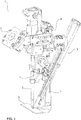
- Figure 1 shows a preferred embodiment of a welding-setting device 1 with an element feed device 3.
- the element feed device 3 is arranged adjacent to the rear part of a C-bracket 5. This reduces the interference contour of the set welding device 1 adjacent to the components B to be connected to one another.
- the setting / welding device 1 preferably comprises a supply unit 7 to which auxiliary welding parts are supplied. From there, the auxiliary welding parts are preferably transferred individually to the element feed device 3, as will be explained in more detail below.
- the set-welding device 1 comprises a known coupling unit 9 for connecting to a robot (not shown).
- the element feed device 3 is preferably connected to the setting / welding device 1 via at least one clamping piece K or shim.
- the clamping piece K forms the basis for connecting the element feed device 3 to setting-welding devices 1 of different types and sizes. In addition, it forms the basis for offering the element feed device 3 as a retrofit kit (see below) and for combining it with existing setting / welding devices 1.
- the set-welding device 1 comprises, in addition to the C-frame, which supports a counter electrode E, an electrode punch S or, in general, a welding electrode.
- the two terms electrode punch S and welding electrode refer to the same part of the set welding device 1. This term is occasionally used differently depending on the setting force to be used for the auxiliary welding part, but is used synonymously here.
- the electrode punch S thus serves as an element for applying a mechanical setting force to the auxiliary welding part and as an electrode for applying an electrical load to the auxiliary welding part.
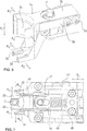
- Figure 2 the setting-welding device 1 is shown again enlarged.
- the element feed device 3 comprises at least one linear drive 10, with a movable end 12 and a fixed end 14.
- the linear drive 10 is a pneumatic cylinder, a hydraulic cylinder or a servomotor or generally any common actuator with which a length change is generated in a targeted manner can be. Via its change in length, the linear drive 10 moves the movable end 12 in a first direction of movement R 10 or in the opposite direction. This is indicated by the arrow R 10 in the Figures 3 and 4th illustrated.
- An element nest 30 is attached to the moving end 12 of the linear drive 10.
- the element nest 30 is used to take over, transport and transfer an individual auxiliary welding joining part 2 at a joint (see below).
- the element nest 30 is preferably guided on a linear guide 16 parallel to the linear drive 10.
- the element nest 30 is preferably attached to a slide 17 which runs on a rail 18.
- the movement of the carriage 17 on the rail 18 can preferably be braked and / or blocked.
- This design of the movement of the element nest 30 with the aid of the linear guide 16 and the slide 17 forms a preferred basis for realizing the functionality of the element feed device 3.
- the element nest 30 described in more detail below is preferably moved with only one linear drive 10 for feeding an auxiliary welding part 2 to the joint.
- this enables the joint and the transfer unit 7 for auxiliary welding parts 2 to be reliably reached.
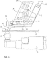
- the element feed device 3 in the preferred configuration with only one linear drive 10 is enlarged in FIG Figure 5 shown.
- the auxiliary welding part 2 is blown to a transfer position via a profile hose 8.
- a preferred locking element prevents the auxiliary welding part 2 from leaving the supply unit 7 in an uncontrolled manner.
- the auxiliary welding joining part 2 is pushed into the element nest 30 with the aid of a plurality of interacting levers and an actuating actuator 6.
- the movable end 12 of the linear drive 10 is preferably connected to the element nest 30 via a mechanical, direction-changing coupling component 20.
- the coupling component 20 is a toggle-like construction which provides a fastening 22, 24, preferably a fastening pin, for the moving end 12 of the linear drive 10 and for the element nest 30.
- the coupling component 20 is preferably formed by a rotatably arranged coupling lever with the plurality of fastening points.
- the fastening pins 22, 24 allow the interconnected components to rotate relative to one another.
- the two fastening pins 22, 24 lie on a common line.
- a further fastening pin 26 is provided on the slide 17 of the linear guide 16. The fastening pin 26 ensures that the coupling component 20 rotates about the fastening 26.
- the coupling component 20 is preferably spring-biased against the moving end 12 of the linear drive 10. This means that only when a threshold force is reached by the moving end 12 of the linear drive 10 during the movement in the first direction of movement R 10 does the coupling component 20 begin to rotate about the fastening 26. In comparison of the Figures 5 and 8th the rotational movement of the coupling component 20 becomes clear. To trigger this rotary movement of the coupling component 20 around the attachment 26, the movement of the slide 17 of the linear guide 16 is preferably blocked. This results in the moving end 12 pressing against the coupling component 20 via the fastening 22 in order to rotate the coupling component 20 about the fastening 26 after the threshold force has been reached.
- the fastening pin 24 is preferably guided in a first elongated hole 29A of a connecting block 28 between the coupling component 20 and the element nest 30, the rotation of the coupling component 20 in the direction of the element nest 30 produces a movement or displacement of the element nest 30 away from the moving end 12 in the direction R 30 (see arrow in Figures 5 and 8th ).
- the movement or displacement of the element nest 30 in the direction R 30 takes place in a second direction of movement, which differs from the first direction of movement R 10 of the linear drive 10. According to the invention, this movement is preferably brought about in the second direction of movement R 30 by the linear drive 10 without an additional drive in the second direction of movement R 30 being required.
- a second elongated hole 29B ensures the direction of movement R 30 of the connecting block 28 and thus of the element nest 30.
- at least one guide pin 32 of the element nest 30 engages in the second elongated hole 29B and only allows movement of the element nest 30 in the direction of the second elongated hole 29B.
- the two directions of movement R 10 and R 30 are preferably characterized in that they are neither parallel nor anti-parallel to one another. Rather, the two directions of movement R 10 and R 30 enclose an angle unequal to 0 ° and unequal to 180 °.
- the slide 17 When the element nest 30 is delivered to the provision unit 7 in the direction R 30 , the slide 17 must be braked in order to trigger the rotation of the coupling component 20 about the fastening 26, in particular a fastening pin or fastening pin.
- the movable end 12 moves of the linear drive 10 in the direction of R 10 .
- the end 12 of the linear drive 10 preferably moves in the opposite direction to the direction R 10 (see FIG Figure 5 ).
- the coupling component 20 rotates around the fastening pin 26 in the opposite direction to R 30 .
- the element nest 30 is moved back into its starting position adjacent to the moving end 12 of the linear drive 10, as shown in FIG Figure 4 is shown.
- the linear drive 10 sets the element nest 30 in the starting position in the direction R 10 to the components B.
- the coupling component 20 is still preferably spring-pretensioned and has not yet been rotated about the fastening pin 26 in the direction of the element nest 30.
- a hold-down device 40 is preferably arranged adjacent to the element nest 30 and upstream of the element nest 30 in the direction R 10.
- the holding-down device 40 is likewise preferably fastened to the slide 17, which is guided by the linear guide 16. Due to the movement of the linear drive 10 in the direction R 10 , the hold-down 40 presses on the components B and blocks further movement of the carriage 17 and the element nest 30 in the direction R 10 .
- the force applied by the hold-down 40 to the components B reduces or eliminates an existing gap between the components B and thus prepares the production of a joint.
- the blocking of the further movement of the carriage 17 by the holding-down device 40 corresponds to the blocking or braking of the carriage 17 on the preparation unit 7 (see above). If the linear actuator 10 also extends after the placing of the blank holder 40 in the direction R 10, ie, the end 12 is moved further in the direction R 10, the linear actuator 10 overcomes the threshold force of the coupling component 20 and starts the rotation of the coupling component 20 about the mounting pin 26th In this way, the element nest 30 is offset in the direction of the joint above a lower electrode E (see FIG Figure 9 ).
- the hold-down 40 is preferably fork-shaped with two arms 42, 44. Between the arms 42, 44 there is a free space into which the element nest 30 moves the auxiliary welding part 2 via the rotation of the coupling component 20 (see FIG Figures 9 and 7th ).
- the auxiliary welding joining part 2 is clamped to the component 2 by the electrode die S and is thereby held (see Figures 10 and 11 ).
- the linear drive 10 is shortened and the end 12 moves in the opposite direction to the direction R 10 .
- the coupling component 20 is rotated back into its starting position and the element nest 30 is removed from the electrode die S, as is the case in comparison with FIG Figures 11 and 12 can be seen.
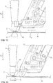
- the element nest has a pair of resilient element jaws 33 and a contour piece 34.
- the element jaws 33 are designed to be resilient relative to one another.
- the element jaws 33 preferably consist of a spring plate. Since the element jaws 33 are opposite one another, they form a resilient pliers-like arrangement in order to hold the auxiliary welding joining part 2 between them in a detachable manner.
- the inner sides of the element jaws 33 facing one another have an inner contour that is adapted to the shape of the auxiliary welding part 2.
- the element jaws 30 are mounted in a floating manner in a plane approximately perpendicular to the joining direction R F. Floating means that the element jaws 33 together in the direction R s according to FIG Figure 6 can evade in order to compensate for possible alignment tolerances, for example with respect to the electrode stamp S.
- the contour piece 34 has a contact contour surface 35, which is discussed in more detail below.
- the contour piece 34 is pivotably held in a coupling block 36 via a retaining pin 37.
- the retaining pin 37 runs through a fork-like clearance approximately parallel to the joining direction R F.
- the contour piece 34 with a holding opening is arranged within the fork-like opening.
- the contour piece 34 can pivot about the retaining pin 37 in the plane approximately perpendicular to the joining direction R F (see arrows R S ).
- the pivoting movement of the contour piece is preferably limited by spring leaves 38 arranged on both sides. These are attached to the side of the coupling block 36 by means of pins 39 and protrude as far as the contour piece 34.
- the pins 39 also ensure that the element nest 30 is guided in the elongated hole 29B of the connecting block 28.
- the element jaws 33 are attached to the contour piece 34.
- the element jaws 33 are floatingly mounted in the same way as the contour piece 34.
- Figure 7 shows a preferred embodiment of the element nest 30 in a view opposite to the joining direction R F , that is, from below. It can be seen in this that the coupling block 36 is held in a recess 48 in a spring-pretensioned manner via a spring 46. This arrangement provides a compensating movement of the contour member 34 and the element jaws 33 along the arrow R A in response to a force acting on the contour piece 34.
- the element nest 30 is preferably a floating mount of the welding auxiliary joining part 2 in the plane perpendicular to the joining direction R F provided that a tolerance compensation or an evasion of the auxiliary welding joining part 2 in three directions within this plane is guaranteed.
- the element feed in the setting / welding device 1 can be implemented with shortened cycle times and with less equipment with regard to sensors and drives. Because according to the invention it is preferably possible, with just one linear drive 10, to take over the auxiliary welding joining part 2 at the supply unit 7 and then to reliably feed it to the joint under the electrode punch S. This is because it is precisely this effective delivery that is guaranteed by the only one linear drive 10 and the movement of the element nest 30 in the two different directions of movement R 10 and R 30 via the direction-changing coupling component 20.
- the element nest 30 implements a tolerance-compensating takeover of an auxiliary welding part 2 on the supply unit 7 and / or a tolerance-compensating arrangement or positioning of the auxiliary welding part 2 at the joint under the electrode die S.
- a tolerance-compensating takeover of an auxiliary welding part 2 on the supply unit 7 and / or a tolerance-compensating arrangement or positioning of the auxiliary welding part 2 at the joint under the electrode die S Denn the floating mounting of the holding position of the auxiliary welding part 2 between the element jaws 33 in combination with the contour piece 34 ensure effective approach accuracy to the supply unit 7 and to the electrode punch S.
- auxiliary welding part 2 is initially positioned approximately exactly above the counter electrode E. However, this position is not necessarily sufficiently precise to then carry out the setting-welding process with the electrode punch S. Instead, in a next step, the electrode die S is moved in the joining direction R F into the contour piece 34 and against the contact contour surface 35.
- the auxiliary welding joining part 2 Due to the floating mounting of the contour piece 34 and the auxiliary welding joining part 2 held by the element jaws 33, the auxiliary welding joining part 2 is optimally aligned with the electrode stamp S and with the counter electrode E by the electrode punch S. Subsequently, the auxiliary welding joining part 2 is clamped to the component B by the electrode stamp S, the element nest 30 is removed and the setting-welding process is carried out.
- the electrode stamp is preferably in a position adjacent to component B and thus to the joint.
- the element nest 30 is moved in the direction R 30 towards the electrode die 20 until the contour piece 34 with the contact contour surface 35 rests on the electrode die S. Since the contact contour surface 35 with the side surface or jacket surface of the electrode die S, in particular the radial outer side thereof, moves to a block, the auxiliary welding part 2 is positioned exactly below the electrode die S via the floating support of the contour piece 34.
- the electrode die S then moves in the joining direction R F and clamps the auxiliary welding part 2 on the component B. After the element nest 30 has been removed from the clamped auxiliary welding part 2 (see FIG Figure 12 ), the set-weld process is carried out.
- the present invention also comprises a retrofit kit with an element feed device 3 preferred according to the invention and / or the element nest 30 for existing set-welding devices.
- the present invention likewise comprises a setting / welding device 1 with the element feed device 3 described above, alone or in combination with the element nest 30 or only with the element nest 30.
- step Z1 the occupied element nest 30 is fed with the linear movement of the linear drive 10 in the first direction of movement R 10 at least to a joint of the auxiliary welding part 2, the auxiliary welding part 2 being supported by the two oppositely arranged and resilient element jaws 33 of the element nest 30 is held releasably.
- step Z2 the hold-down 40 attached to the linear drive 10 is placed on the at least one component B.
- step Z3 the element nest 30 moves via the mechanical direction-changing coupling component 20 in the second direction of movement R 30 to position the auxiliary welding part 2 at the joint by moving the linear drive 10 further in the first direction of movement R 10 .
- step Z4 the element nest 30 is moved to a stop against the electrode die S, whereby the mechanical stop alignment of the element nest 30 rests laterally on the electrode die S and the auxiliary welding part 2 is held between the element jaws 33 in the joining direction R F and positioned below the electrode die S.
- the auxiliary welding part 2 is clamped by the electrode die S in the joining direction R F against the adjacent component B at the joint, and in the next step Z6, the element nest 33 is removed from the electrode die S. This also results in the auxiliary welding joining part 2 being released from the resilient hold of the element jaws 33.
- the element supply method is used not only to supply the auxiliary welding part 2 to the joint, but also to take over an auxiliary welding part at the supply unit 7. It is therefore preferred in a step Z7 to block a movement of the element nest 30 parallel to the first direction of movement R 10 of the linear drive 10 adjacent to the supply unit or transfer unit 7 for an auxiliary welding part. In this way, the element nest 30 is moved via the mechanical direction-changing coupling component 20 in the second movement direction R 30 in the direction of the provision unit 7. This movement serves to position the element nest 30 on the provision unit 7 by moving the linear drive 10 further in the first direction of movement R 10 .
- step Z8 the element nest 30 is moved against the stop on the provision unit 7.
- the mechanical stop alignment of the element nest, in particular the contour piece 34 with its contact contour surface 35, is moved to a block against the stop 50 of the supply unit 7 and rests there.
- the two element jaws 33 which are resiliently arranged relative to one another, are positioned in a transfer position of the provision unit 7 in order to receive the auxiliary welding part 2.
- step Z9 the auxiliary welding part 2 is moved from the supply unit 7 between the element jaws 33 of the element nest 30, so that the auxiliary welding part 2 is detachably held there.
- the element nest 30 is parallel to the first direction of movement R 10 of the linear drive 10 is moved opposite to the first direction of movement R 10 preferably blocked movement is reset whereby the element nest 30 via the mechanical direction-changing coupling component 20 against the second direction of movement R 30 in a starting position. After this reset has been completed, the occupied element nest 30 is advanced to the joint with the linear movement of the linear drive 10 in the first direction of movement R 10.
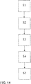
- a first step S1 the occupied element nest 30 is fed with the at least one drive 10 to the joint adjacent to the electrode die S, the auxiliary welding part 2 being releasably held by the two oppositely arranged and resilient element jaws 33 of the element nest 30 .
- the element nest 30 is moved to a stop on the electrode die S, whereby the mechanical stop alignment of the element nest 30, i.e. the contour piece 34 with the contact contour surface 35, rests on the side of the electrode die S and the auxiliary welding part is held between the element jaws 33 in the joining direction R.
- F is positioned below the electrode stamp S.
- the element nest 30 with the auxiliary welding joining part 2 held therein is positioned adjacent to the joint, preferably adjacent to the counter electrode E on the component.
- the electrode stamp S is then subsequently moved in the joining direction R F until the contour piece 34 with the contact contour surface 35 rests on the outside of the electrode stamp S.
- the auxiliary welding part 2 is also positioned appropriately under the electrode die S via the floating mounting of the auxiliary welding part 2 in the element nest 30.
- the auxiliary welding part 2 is preferably clamped in step S3 by the electrode die S in the joining direction R F against the adjacent component B at the joint and, in step S4, the element nest 30 is removed from the electrode stamp S and thereby the auxiliary welding part 2 is released from the resilient hold the element jaws 33.
- tolerances are compensated in a supplementary step in a plane approximately perpendicular to the joining direction R F between the electrode die S and the element nest 30 when the element nest 30 is moved to the stop Electrode stamp S with the aid of the floating mounting of the element nest 30 in relation to its attachment to the element feed device.
Abstract
Eine Elementzufuhrvorrichtung 3 eines Setz-Schweiß-Geräts 1 für ein Schweißhilfsfügeteil 2 mit einem Kopf und einem Schaft, welche die folgenden Merkmale aufweist: einen Linearantrieb 10, der an dem Schweiß-Setz-Gerät 1 befestigbar ist und der an einem bewegbaren Ende 12 ein Elementnest 30 aufweist, in welchem ein Schweißhilfsfügeteil 2 von einer Übergabeeinheit 7 lösbar aufnehmbar ist, und das Elementnest 30 ist über eine Linearbewegung des Linearantriebs 10 in eine erste Bewegungsrichtung R<sub>10</sub> zumindest zu einer Fügestelle des Schweißhilfsfügeteils 2 bewegbar, wobei das Elementnest 30 in einer Ebene annähernd senkrecht zu einer Fügerichtung R<sub>F</sub> schwimmend gelagert ist, um über eine mechanische Anschlagausrichtung anliegend an einem Elektrodenstempel S in Fügerichtung R<sub>F</sub> unterhalb des Elektrodenstempels S positionierbar zu sein, und/oder wobei das Elementnest 30 mit dem bewegbaren Ende 12 des Linearantriebs 10 über eine mechanische richtungsändernde Kopplungskomponente 20 verbunden ist, so dass das Elementnest 30 mittels der Linearbewegung des Linearantriebs 10 in der ersten Bewegungsrichtung R<sub>10</sub> in eine zweite Bewegungsrichtung R<sub>30</sub> bewegbar ist, so dass das Schweißhilfsfügeteil 2 an der Fügestelle positionierbar ist, wobei die zweite Bewegungsrichtung R<sub>30</sub> in einem Winkel ungleich 0° und ungleich 180° zur ersten Bewegungsrichtung R<sub>10</sub> orientiert ist.An element feed device 3 of a setting-welding device 1 for a welding auxiliary joining part 2 with a head and a shaft, which has the following features: a linear drive 10 which can be attached to the welding-setting device 1 and which is attached to a movable end 12 Element nest 30, in which an auxiliary welding part 2 can be detachably received by a transfer unit 7, and the element nest 30 can be moved in a first direction of movement R <sub> 10 </sub> at least to a joint of the auxiliary welding part 2 via a linear movement of the linear drive 10, wherein the element nest 30 is floating in a plane approximately perpendicular to a joining direction R <sub> F </sub> in order to abut an electrode stamp S in joining direction R <sub> F </sub> below the electrode stamp S via a mechanical stop alignment to be positionable, and / or wherein the element nest 30 with the movable end 12 of the linear drive 10 via a mechanical direction-changing coupling processing component 20 is connected, so that the element nest 30 can be moved by means of the linear movement of the linear drive 10 in the first direction of movement R <sub> 10 </sub> in a second direction of movement R <sub> 30 </sub>, so that the auxiliary welding part 2 can be positioned at the joint, the second direction of movement R <sub> 30 </sub> being oriented at an angle not equal to 0 ° and not equal to 180 ° to the first direction of movement R <sub> 10 </sub>.
Description
Die vorliegende Erfindung betrifft eine Elementzufuhrvorrichtung eines Setz-Schweiß-Geräts für ein Schweißhilfsfügeteil mit einem Kopf und einem Schaft. Des Weiteren betrifft vorliegende Erfindung ein Elementnest eines Schweißhilfsfügeteils für ein Setz-Schweiß-Gerät, sowie ein Setz-Schweiß-Gerät, welches mit der Elementzufuhrvorrichtung und/oder dem genannten Elementnest ausgestattet ist. Zudem betrifft vorliegende Erfindung einen Nachrüstsatz einer Elementzufuhrvorrichtung sowie eines Elementnests für ein existierendes Setz-Schweiß-Gerät. Des Weiteren sind Zufuhrverfahren eines Schweißhilfsfügeteils zu einer Fügestelle in einem Setz-Schweiß-Gerät definiert. Dazu verwendet das jeweilige Zufuhrverfahren die oben genannte Elementzufuhrvorrichtung und/oder das Elementnest.The present invention relates to an element feed device of a setting-welding device for a welding auxiliary joining part with a head and a shaft. The present invention also relates to an element nest of a welding auxiliary joining part for a setting-welding device, as well as a setting-welding device which is equipped with the element feed device and / or the mentioned element nest. The present invention also relates to a retrofit kit for an element feed device and an element nest for an existing set-welding device. In addition, methods of feeding an auxiliary welding part to a joint in a setting / welding device are defined. For this purpose, the respective feed method uses the above-mentioned element feed device and / or the element nest.
Im Stand der Technik sind verschiedene Setz-Schweiß-Geräte bekannt, denen über teilweise sehr aufwändige Elementzufuhrsysteme Schweißhilfsfügeteile zugeführt werden. Aufwendig sind in diesem Zusammenhang die Elementzufuhrsysteme deshalb, weil mithilfe mehrerer Antriebe die Wege zwischen einer Übergabeeinheit für das Schweißhilfsfügeteil und der Fügestelle überbrückt werden müssen. Zudem ist es erforderlich, dass die Positionierung der Elementzufuhrvorrichtung an der Übergabeeinheit für das Schweißhilfsfügeteil sowie an der Fügestelle zur Übergabe des Schweißhilfsfügeteils an den Elektrodenstempel mit ausreichender Sensorik abgesichert werden muss.Various set-welding devices are known in the prior art, to which auxiliary welding parts are supplied via sometimes very complex element supply systems. The element feed systems are complex in this context because the paths between a transfer unit for the auxiliary welding part and the joint must be bridged with the aid of several drives. In addition, it is necessary that the positioning of the element feed device on the transfer unit for the auxiliary welding part and at the joint for transferring the auxiliary welding part to the electrode die must be secured with sufficient sensors.
In diesem Zusammenhang offenbart
In
Im Hinblick auf die Vielzahl der im Stand der Technik bekannten Zufuhrkonstruktionen und Systeme an Setz-Schweiß-Geräten ist es die Aufgabe vorliegender Erfindung, eine einfachere Elementzufuhrvorrichtung mit einem effizienteren konstruktiven Aufwand und Steueraufwand bereitzustellen.In view of the large number of feed constructions and systems of set-welding devices known in the prior art, the object of the present invention is to provide a simpler element feed device with a more efficient structural effort and control effort.
Die obige Aufgabe wird durch eine Elementzufuhrvorrichtung eines Setz-Schweiß-Geräts für ein Schweißhilfsfügeteil mit einem Kopf und einem Schaft gemäß dem unabhängigen Patentanspruch 1 gelöst. Des Weiteren löst obige Aufgabe ein Elementnest eines Schweißhilfsfügeteils in einem Setz-Schweiß-Gerät, vorzugsweise in einer Elementzufuhrvorrichtung eines Setz-Schweiß-Geräts, gemäß dem unabhängigen Patentanspruch 8. Außerdem wird obige Aufgabe durch ein Setz-Schweiß-Gerät für ein Schweißhilfsfügeteil mit einem Kopf und einem Schaft in Kombination mit der oben genannten Elementzufuhrvorrichtung sowie in Kombination bzw. oder in Kombination mit dem oben genannten Elementnest gemäß dem unabhängigen Patentanspruch 12 gelöst. Außerdem umfasst vorliegende Erfindung einen Nachrüstsatz für eine Elementzufuhrvorrichtung oder ein Elementnest gemäß dem unabhängigen Patentanspruch 13. Des Weiteren wird im Zusammenhang mit der bereits oben genannten Elementzufuhrvorrichtung ein Zufuhrverfahren gemäß dem unabhängigen Patentanspruch 14 sowie ein Zufuhrverfahren eines Schweißhilfsfügeteils für ein Setz-Schweiß-Gerät in Kombination mit dem oben genannten Elementnest gemäß dem unabhängigen Patentanspruch 19 offenbart. Weiterentwicklungen und Modifikationen vorliegender Erfindung gehen aus der folgenden Beschreibung, den begleitenden Zeichnungen sowie den anhängenden Patentansprüchen hervor.The above object is achieved by an element feed device of a setting-welding device for a welding auxiliary joining part with a head and a shaft according to
Die erfindungsgemäße Elementzufuhrvorrichtung eines Setz-Schweiß-Geräts für ein Schweißhilfsfügeteil mit einem Kopf und einem Schaft weist die folgenden Merkmale auf: einen Linearantrieb, der an dem Schweiß-Setz-Gerät befestigbar ist und der an einem bewegbaren Ende ein Elementnest aufweist, in welchem ein Schweißhilfsfügeteil, insbesondere von einer Übergabeeinheit, lösbar aufnehmbar ist, und das Elementnest ist über eine Linearbewegung des Linearantriebs in eine erste Bewegungsrichtung zumindest zu einer Fügestelle des Schweißhilfsfügeteils bewegbar, wobei gemäß Alternative 1 das Elementnest in einer Ebene annähernd senkrecht zu einer Fügerichtung schwimmend gelagert ist, um über eine mechanische Anschlagausrichtung anliegend an einem Elektrodenstempel in Fügerichtung unterhalb des Elektrodenstempels positionierbar zu sein, und/oder wobei gemäß Alternative 2 das Elementnest mit dem bewegbaren Ende des Linearantriebs über eine mechanische richtungsändernde Kopplungskomponente verbunden ist, so dass das Elementnest mittels der Linearbewegung des Linearantriebs in der ersten Bewegungsrichtung in eine zweite Bewegungsrichtung bewegbar ist, so dass das Schweißhilfsfügeteil an der Fügestelle positionierbar ist, wobei die zweite Bewegungsrichtung in einem Winkel ungleich 0° und ungleich 180° zur ersten Bewegungsrichtung orientiert ist.The element feed device according to the invention of a setting-welding device for a welding auxiliary joining part with a head and a shaft has the following features: a linear drive which can be attached to the welding-setting device and which has an element nest at a movable end in which a Auxiliary welding part can be detachably received, in particular by a transfer unit, and the element nest can be moved in a first direction of movement via a linear movement of the linear drive at least to a joint of the auxiliary welding part, whereby according to
Die erfindungsgemäße Elementzufuhrvorrichtung ist darauf gerichtet, die Konstruktion bekannter Setz-Schweiß-Geräte im Hinblick auf die Elementzufuhr zu vereinfachen. Vereinfachung betrifft dabei die Nutzung von Sensorik, Antriebstechnik und erforderliche Störkontur, um ein Schweißhilfsfügeteil zunächst von einer Übergabeeinheit zu übernehmen und nachfolgend der Fügestelle effektiv zuzuführen. Im Hinblick auf diese übergeordnete Thematik beschreibt die erfindungsgemäße Elementzufuhr zwei alternative Ansätze, die einzeln oder in Kombination miteinander genutzt werden können. Beide Alternativen 1 und 2 arbeiten dazu grundsätzlich mit mindestens einem Linearantrieb zusammen, der an dem Schweiß-Setz-Gerät befestigbar ist. Gemäß einer bevorzugten Ausgestaltung vorliegender Erfindung ist die Verwendung nur eines Linearantriebs ausreichend, um eine verlässliche Elementzufuhr zur Fügestelle zu realisieren. Nichtsdestotrotz ist es ebenfalls denkbar, beispielsweise das unten näher erläuterte Elementnest auch mit der Kombination von beispielsweise zwei Linearantrieben der Fügestelle zuzuführen.The element feed device according to the invention is aimed at simplifying the construction of known set-welding devices with regard to the element feed. Simplification relates to the use of sensors, drive technology and the necessary interfering contour in order to initially take over a welding auxiliary joining part from a transfer unit and then effectively feed it to the joint. With regard to this overarching topic, the element feed according to the invention describes two alternative approaches that can be used individually or in combination with one another. Both
An einem bewegbaren Ende des Linearantriebs, insbesondere an dem Arbeitsende des Linearantriebs, ist das Elementnest bewegbar angeordnet. Da man sich vorzugsweise auf die Nutzung nur eines Linearantriebs beschränkt, bewegt dieser Linearantrieb das Elementnest in eine erste Bewegungsrichtung, die der Linearantrieb vorgibt. Das Elementnest hat eine gewisse Vororientierung, so dass in diesem Elementnest das Schweißhilfsfügeteil mit seiner Längsachse ausgerichtet annähernd parallel zur späteren Fügerichtung aufnehmbar ist. Das Elementnest zeichnet sich weiterhin dadurch aus, dass es in einer Ebene annähernd senkrecht zur Fügerichtung schwimmend gelagert ist. Diese schwimmende Lagerung eröffnet eine toleranzbehaftete Zufuhr des im Elementnest aufgenommenen Schweißhilfsfügeteils zur Fügestelle. Toleranzbehaftet bedeutet in diesem Zusammenhang, dass trotz einer möglichst genauen Anordnung des Schweißhilfsfügeteils unterhalb des Elektrodenstempels gewisse Abweichungen zwischen einer Längsachse des Schweißhilfsfügeteils und einer Längsachse des Elektrodenstempels vorhanden sein können. Das heißt im Besonderen, dass das Schweißhilfsfügeteil nicht notwendigerweise koaxial zum Elektrodenstempel angeordnet sein muss. Die schwimmende Lagerung des Elementnests garantiert aber, dass mit einem wirksamen direkten oder indirekten Kontakt zwischen dem Elementnest und dem Elektrodenstempel eine bevorzugt koaxiale Ausrichtung zwischen dem Schweißhilfsfügeteil und dem Elektrodenstempel erfolgt. Mit dieser gezielten Ausrichtung zwischen dem Schweißhilfsfügeteil und dem Elektrodenstempel wird die danach folgende Herstellung der Fügeverbindung vorbereitet.The element nest is movably arranged at a movable end of the linear drive, in particular at the working end of the linear drive. Since it is preferred to limit oneself to the use of only one linear drive, this linear drive moves the element nest in a first direction of movement that is specified by the linear drive. The element nest has a certain pre-orientation, so that in this element nest the welding auxiliary joining part can be received with its longitudinal axis aligned approximately parallel to the later joining direction. The element nest is also distinguished by the fact that it is floating in a plane approximately perpendicular to the joining direction. This floating mounting opens up a tolerance-afflicted supply of the welding auxiliary joining part received in the element nest to the joint. In this context, subject to tolerance means that, despite the most precise possible arrangement of the auxiliary welding part below the electrode die, certain deviations may exist between a longitudinal axis of the auxiliary welding part and a longitudinal axis of the electrode die. This means in particular that the auxiliary welding part does not necessarily have to be arranged coaxially with the electrode punch. The floating mounting of the element nest guarantees, however, that with an effective direct or indirect contact between the element nest and the electrode stamp, a preferably coaxial alignment takes place between the auxiliary welding part and the electrode stamp. With this targeted alignment between the auxiliary welding part and the electrode stamp, the subsequent production of the joint is prepared.
Aus dem oben beschriebenen Zusammenhang ist erkennbar, dass der Elektrodenstempel aufgrund seines Kontakts mit dem Elementnest in der Lage ist, das Elementnest innerhalb der schwimmenden Lagerung derart zu verschieben und auszurichten, dass sich eine koaxiale Anordnung zwischen Schweißhilfsfügeteil und Elektrodenstempel ergibt. Dieses Zusammenwirken erfordert weder eine zusätzliche Sensorik zum Erkennen der Position von Elementnest und/oder Elektrodenstempel noch zusätzliche Antriebe, um auf eine genaue koaxiale Ausrichtung des Schweißhilfsfügeteils unterhalb des Elektrodenstempels hinzuwirken. Insofern erzielt diese rein konstruktive Lösung ohne zusätzlichen elektronischen Steuer- und Antriebsaufwand eine effiziente Positionierung des Schweißhilfsfügeteils unterhalb des Elektrodenstempels.From the relationship described above, it can be seen that the electrode punch, due to its contact with the element nest, is able to move and align the element nest within the floating bearing in such a way that a coaxial arrangement results between the auxiliary welding part and the electrode punch. This interaction requires neither an additional sensor system for recognizing the position of the element nest and / or electrode stamp nor additional drives in order to work towards an exact coaxial alignment of the auxiliary welding part below the electrode stamp. In this respect, this purely constructive solution achieves efficient positioning of the auxiliary welding joining part below the electrode stamp without additional electronic control and drive expenditure.
Gemäß der weiteren erfindungsgemäßen Alternative 2, die allein oder in Kombination mit dem oben diskutierten Elementnest gemäß Alternative 1 eingesetzt wird, ist das Elementnest mit dem bewegbaren Ende des Linearantriebs über eine mechanische richtungsändernde Kopplungskomponente verbunden. Die Bezeichnung mechanische richtungsändernde Kopplungskomponente unterstreicht zunächst, dass mit ihr eine Abweichung der Bewegungsrichtung des Elementnests von der ersten Bewegungsrichtung des Linearantriebs realisiert wird. Zu diesem Zweck ist es ebenfalls nicht nötig, dass ein weiterer Linearantrieb mit dem ersten Linearantrieb kombiniert wird. Vielmehr werden bewegbare Teile derart zusammengeschaltet, dass mithilfe der nur einen Linearbewegung des Linearantriebs das Elementnest mit dem zuzuführenden Schweißhilfsfügeteil auch in eine zweite Bewegungsrichtung bewegbar ist.According to the
Zu diesem Zweck ist bevorzugt das Elementnest linear oder rotatorisch verschiebbar gelagert, wobei diese lineare Bewegungsrichtung ungleich der Bewegungsrichtung des Linearantriebs ist. Zudem ist es bevorzugt, den Linearantrieb über die richtungsändernde Kopplungskomponente mit dem Elementnest in seiner linear verschiebbaren Lagerung zu verbinden. Diese Kopplungskomponente zeichnet aus, dass sie mit dem Linearantrieb und dem Elementnest über entsprechende Befestigungspunkte, vorzugsweise Befestigungszapfen, drehbar verbunden ist. Zudem gibt es einen dritten Befestigungspunkt, vorzugsweise in Form eines Befestigungszapfens oder -stifts, der ebenfalls auch als Drehpunkt für diese Kopplungskomponente dient. Dieser Drehpunkt liegt außerhalb einer Verbindungslinie zwischen den beiden Befestigungspunkten zum Linearantrieb und zum Elementnest, so dass mithilfe der richtungsändernden Komponente eine Linearbewegung des Linearantriebs in eine andere Bewegungsrichtung, insbesondere Linearbewegung, des verschiebbaren Elementnests unwandelbar ist.For this purpose, the element nest is preferably mounted in a linear or rotationally displaceable manner, this linear direction of movement not being the same as the direction of movement of the linear drive. In addition, it is preferred to connect the linear drive to the element nest in its linearly displaceable mounting via the direction-changing coupling component. This coupling component is characterized by the fact that it is rotatably connected to the linear drive and the element nest via corresponding fastening points, preferably fastening pins. In addition, there is a third fastening point, preferably in the form of a fastening stud or pin, which also serves as a pivot point for this coupling component. This pivot point lies outside a connecting line between the two attachment points to the linear drive and to the element nest, so that with the aid of the direction-changing component, a linear movement of the linear drive in a different direction of movement, in particular a linear movement, of the displaceable element nest cannot be changed.
In diesem Zusammenhang ist es von Bedeutung, dass die richtungsändernde Komponente derart ausgelegt ist, dass die lineare Bewegungsrichtung des Linearantriebs und die Bewegungsrichtung des Elementnests nach der richtungsändernden Komponente in einem bestimmten Winkel zueinander ausgerichtet sind, der ungleich 0° und ungleich 180° ist. Gemäß einer bevorzugten Ausgestaltung dieser erfindungsgemäßen Alternative schließen die beiden, insbesondere linearen, Bewegungsrichtungen einen stumpfen Winkel ein.In this context, it is important that the direction-changing component is designed in such a way that the linear direction of movement of the linear drive and the direction of movement of the element nest after the direction-changing component are aligned at a certain angle to one another, which is not equal to 0 ° and not equal to 180 °. According to a preferred embodiment of this alternative according to the invention, the two, in particular linear, directions of movement enclose an obtuse angle.
Gemäß einer bevorzugten Ausgestaltung der Elementzufuhrvorrichtung nach der zweiten Alternative, die die mechanisch richtungsändernde Kopplungskomponente verwendet, weist die richtungsändernde Kopplungskomponente einen drehbar angeordneten Kopplungshebel auf, der an zueinander beabstandeten zwei Befestigungspunkten mit dem Linearantrieb und dem Elementnest verbunden ist und der an einem dritten Befestigungspunkt drehbar befestigt ist, wobei der dritte Befestigungspunkt außerhalb einer gedachten Verbindungslinie zwischen dem ersten und dem zweiten Befestigungspunkt liegt.According to a preferred embodiment of the element supply device according to the second alternative, which uses the mechanically direction-changing coupling component, the direction-changing coupling component has a rotatably arranged coupling lever which is connected to the linear drive and the element nest at two spaced apart fastening points and which is rotatably fastened to a third fastening point is, wherein the third fastening point lies outside an imaginary connecting line between the first and the second fastening point.
Gemäß der obigen Beschreibung ist die richtungsändernde Kopplungskomponente vorzugsweise ähnlich einem Kniehebelgelenk ausgebildet. Von Bedeutung ist in diesem Zusammenhang jedoch, dass die richtungsändernde Kopplungskomponente zur Übertragung einer linearen Bewegung und zur Umwandlung der Bewegungsrichtung dieser linearen Bewegung in eine andere Bewegungsrichtung dient. Die Kopplungskomponente ist nicht dafür ausgelegt, dass eine Drehmomentänderung oder eine Kraftänderung durch die Kopplungskomponente realisiert werden soll. Vielmehr soll die Kopplungskomponente auf belastbare und verlässliche Weise sicherstellen, dass mit der nur einen Linearbewegung des vorzugsweise nur einen Linearantriebs auch eine Zustellbewegung des Elementnests in eine zweite Bewegungsrichtung realisiert werden kann. Denn auf diese Weise wird auch ohne zusätzliche Sensorik und Antriebstechnik mit dem nur einen Linearantrieb eine relativ positionsgenaue Anordnung des Schweißhilfsfügeteils unter dem Elektrodenstempel bereitgestellt.According to the above description, the direction-changing coupling component is preferably designed similar to a toggle joint. In this context, however, it is important that the direction-changing coupling component serves to transmit a linear movement and to convert the direction of movement of this linear movement into another direction of movement. The coupling component is not designed for a change in torque or a change in force should be realized by the coupling component. Rather, the coupling component should ensure in a resilient and reliable manner that with only one linear movement of the preferably only one linear drive, an infeed movement of the element nest in a second direction of movement can also be realized. Because in this way, even without additional sensors and drive technology, with the only one linear drive, a relatively positionally accurate arrangement of the auxiliary welding part under the electrode die is provided.
Wie bereits oben an verschiedenen Stellen angedeutet worden ist, wird vorzugsweise die Elementzufuhrvorrichtung der bevorzugten Ausführungsformen mit nur einem Linearantrieb realisiert. Denn dieser nur eine Linearantrieb ist ausreichend, um das Elementnest verlässlich der Fügestelle zuzuführen, selbst wenn dazu zwei winklig zueinander angeordnete Linearbewegungen erforderlich sein sollten.As has already been indicated above at various points, the element feed device of the preferred embodiments is preferably implemented with only one linear drive. This is because this only one linear drive is sufficient to reliably feed the element nest to the joint, even if two linear movements arranged at an angle to one another should be required for this.
Gemäß einer weiteren bevorzugten Ausgestaltung der Elementzufuhrvorrichtung in Kombination mit der oben genannten Alternative 1 der ersten Ausgestaltung oder gemäß einer der vorhergehenden bevorzugten Ausgestaltungen weist das Elementnest zwei einander gegenüberliegend angeordnete und relativ zueinander federnde Elementbacken auf, mit denen das Schweißhilfsfügeteil lösbar haltbar ist und die in einer Ebene senkrecht zu der Fügerichtung des Schweiß-Setz-Geräts schwimmend gelagert sind.According to a further preferred embodiment of the element feed device in combination with the above-mentioned
Aus bekannten Setz-Schweiß-Geräten gehen bereits Elementnester hervor, in denen das zuzuführende Schweißhilfsfügeteil zwischen Elementbacken gehalten wird. Größtenteils sind diese Elementbacken über Hebelverbindungen derart bewegbar, dass sie scherenartig oder zangenartig das Schweißhilfsfügeteil halten und wieder freigeben können. Für eine derartige Konstruktion ist es natürlich erforderlich, gezielte Antriebstechnik und meist auch Sensorik einzusetzen. Um diese Konstruktion zu vereinfachen, nutzt das erfindungsgemäß bevorzugte Elementnest zwei federnde Elementbacken, die relativ zueinander federnd bewegbar sind. Das bedeutet, dass entweder nur eine Elementbacke federnd gelagert ist oder dass beide Elementbacken federn können, um ein Schweißhilfsfügeteil klemmend festhalten aber auch freigeben zu können. Diese bevorzugte Konstruktion garantiert beispielsweise, dass an einer Übergabeeinheit ein Schweißhilfsfügeteil zwischen die Elementbacken geklemmt werden kann. Damit ist für den weiteren Transportweg bzw. den Zufuhrweg zur Fügestelle das Schweißhilfsfügeteil zwischen den Elementbacken verlässlich gehalten. In gleicher Weise realisiert dieser federnde Halt des Schweißhilfsfügeteils zwischen den relativ zueinander federnd gelagerten Elementbacken, dass bei einer Klemmung des Schweißhilfsfügeteils zwischen dem Elektrodenstempel und einem Bauteil das Elementnest von dem Schweißhilfsfügeteil abgezogen werden kann. Somit ist auch ein einfaches Lösen des Schweißhilfsfügeteils aus dem Elementnest durch die federnd gelagerten Elementbacken möglich.Element nests in which the welding auxiliary joining part to be fed is held between element jaws already emerge from known set-welding devices. For the most part, these element jaws can be moved via lever connections in such a way that they hold the auxiliary welding part like a pair of scissors or tongs and can release it again. For such a construction it is of course necessary to use specific drive technology and mostly also sensors. In order to simplify this construction, the element nest preferred according to the invention uses two resilient element jaws which are resiliently movable relative to one another. This means that either only one element jaw is resiliently mounted or that both element jaws can spring in order to be able to hold a welding auxiliary joining part in a clamping manner, but also to be able to release it. This preferred construction guarantees, for example, that an auxiliary welding part can be clamped between the element jaws on a transfer unit. The auxiliary welding part is thus reliably held between the element jaws for the further transport route or the supply route to the joint. In the same way, this resilient hold of the auxiliary welding part between the element jaws, which are spring-mounted relative to one another, ensures that the element nest can be pulled off the auxiliary welding part when the auxiliary welding part is clamped between the electrode die and a component. A simple detachment of the auxiliary welding joining part from the element nest is thus also possible by means of the spring-mounted element jaws.
Gemäß einer weiteren bevorzugten Ausgestaltung des im vorhergehenden Absatz beschriebenen Elementnests oder der Elementzufuhrvorrichtung weist das Elementnest als mechanische Anschlagausrichtung ein Konturstück mit einer Anlagekonturfläche angepasst an eine äußere Form eines Elektrodenstempels oder allgemein angepasst an einen Anschlag auf, wobei insbesondere eine Flächennormale der Anlagekonturfläche senkrecht zur Fügerichtung des Elektrodenstempels orientiert ist.According to a further preferred embodiment of the element nest described in the preceding paragraph or of the element feed device, the element nest has as a mechanical stop alignment a contour piece with a contact contour surface adapted to an outer shape of an electrode punch or generally adapted to a stop, wherein in particular a surface normal of the contact contour surface is oriented perpendicular to the joining direction of the electrode punch.
Mit dem Ziel, den sensorischen Erfassungsaufwand der Elementzuführung im Vergleich zu Lösungen im Stand der Technik zu reduzieren, weist das erfindungsgemäß bevorzugte Elementnest ein Konturstück auf, welches mit einer Anlagekonturfläche gegen den Elektrodenstempel oder gegen einen Anschlag einer Bereitstellungseinheit verfahrbar ist. Zwar erfordert auch diese Konzeption des Elementnests eine gewisse Abstimmung der Bewegung des Elementnests auf die Position des Elektrodenstempels, es ist aber nicht erforderlich, dass sensorisch permanent der Abstand zwischen sich bewegendem Elementnest und sich annäherndem Elektrodenstempel erfasst wird. Vielmehr dient die Anlagekonturfläche des Konturstücks des Elementnests dazu, dass das Elementnest seitlich gegen den Elektrodenstempel des Setz-Schweiß-Geräts verfahrbar ist. Sobald die Anlagekonturfläche am Elektrodenstempel seitlich anliegt, wird die weitere Zustellbewegung des Elementnests gestoppt.With the aim of reducing the sensor-based detection effort of the element feed compared to solutions in the prior art, the element nest preferred according to the invention has a contour piece which can be moved with a contact contour surface against the electrode stamp or against a stop of a supply unit. Although this conception of the element nest also requires a certain coordination of the movement of the element nest with the position of the electrode stamp, it is not necessary for the distance between the moving element nest and the approaching electrode stamp to be permanently detected by sensors. Rather, the contact contour surface of the contour piece of the element nest serves to ensure that the element nest can be moved laterally against the electrode stamp of the setting / welding device. As soon as the contact contour surface rests laterally on the electrode die, the further infeed movement of the element nest is stopped.
Während das Konturstück mit der Anlagekonturfläche einerseits dazu dient, das Elementnest direkt am Elektrodenstempel zu positionieren, sorgt es ebenfalls dafür, dass das im Elementnest befindliche Schweißhilfsfügeteil passend zur Längsachse, vorzugsweise koaxial dazu, des Elektrodenstempels ausgerichtet wird. Denn für ein beschädigungsfreies Verfahren des Elementnests gegen den Elektrodenstempel mithilfe des Konturstücks ist es erforderlich, dass das Konturstück vorzugsweise in Richtung senkrecht zum Elektrodenstempel schwimmend gelagert ist. Auf diese Weise kann die Anlagekonturfläche verlässlich in Kontakt mit der seitlichen Fläche des Elektrodenstempels gebracht werden, ohne dass dabei der Elektrodenstempel beschädigt wird. Denn selbst wenn die lineare Zustellbewegung des Elementnests und somit des Konturstücks zum Elektrodenstempel eine Bewegung über die Außenfläche des Elektrodenstempels hinaus zulassen würde, kann das Konturstück aufgrund der schwimmenden Lagerung gegen eine bevorzugte Federkraft in seine Halterung im Elementnest eintauchen. Diese schwimmende Lagerung gibt somit vorzugsweise dem Konturstück eine zusätzliche Bewegungsfreiheit in einer Ebene, die annähernd senkrecht zur Fügerichtung des Setz-Schweiß-Geräts oder zur Längsachse des Elektrodenstempels angeordnet ist.While the contour piece with the contact contour surface serves on the one hand to position the element nest directly on the electrode die, it also ensures that the auxiliary welding part located in the element nest is aligned with the longitudinal axis of the electrode die, preferably coaxially with it. This is because for a damage-free movement of the element nest against the electrode die with the aid of the contour piece, it is necessary that the contour piece is preferably floatingly supported in the direction perpendicular to the electrode die. In this way, the contact contour surface can be reliably brought into contact with the lateral surface of the electrode stamp without the electrode stamp being damaged in the process. Because even if the linear infeed movement of the element nest and thus the contour piece to the electrode die would allow a movement beyond the outer surface of the electrode die, the contour piece can dip into its holder in the element nest due to the floating mounting against a preferred spring force. This floating mounting thus preferably gives the contour piece additional freedom of movement in a plane which is arranged approximately perpendicular to the joining direction of the set-welding device or to the longitudinal axis of the electrode die.
Um eine optimale und genaue Anlage des Konturstücks am Elektrodenstempel zu gewährleisten, ist die Anlagekonturfläche des Konturstücks an die äußere seitliche Form, vorzugsweise die radiale Außenseite des Elektrodenstempels, angepasst. Entsprechend erstreckt sich eine Flächennormale der Anlagekonturfläche senkrecht zur Fügerichtung oder zur Längsachse des Elektrodenstempels.In order to ensure optimal and precise contact between the contour piece and the electrode stamp, the contact contour surface of the contour piece is adapted to the outer lateral shape, preferably the radial outside of the electrode stamp. Correspondingly, a surface normal of the contact contour surface extends perpendicular to the joining direction or to the longitudinal axis of the electrode die.
Gemäß einer weiteren bevorzugten Ausgestaltung des zuvor beschriebenen Elementnests sind die Elementbacken an dem Konturstück seitlich federnd befestigt und das Konturstück ist in mindestens zwei, vorzugsweise in drei, Richtungen innerhalb einer Ebene senkrecht zur Fügerichtung federnd auslenkbar angeordnet.According to a further preferred embodiment of the element nest described above, the element jaws are laterally resiliently attached to the contour piece and the contour piece is at least two, preferably in three, directions within a plane perpendicular to the joining direction resiliently deflectable.
Es wurde bereits oben auf die bevorzugte Ausgestaltung bzw. Befestigung des Konturstücks im Elementnest hingewiesen. Diese schließt ein, dass das Konturstück in einer Ebene annähernd senkrecht zur Fügerichtung bzw. zur Längsachse des Elektrodenstempels schwimmend gelagert ist. Dazu kann das Konturstück für einen bestimmten Federweg in die Befestigung im Elementnest eintauchen und wieder durch die Federkraft heraus gedrückt werden. Da das Konturstück senkrecht auf den Elektrodenstempel zubewegt wird, ergibt diese federnde Lagerung des Konturstücks eine schwimmende Lagerung in einer Ebene annähernd senkrecht zur Fügerichtung und zur Längsachse des Elektrodenstempels. Da nun vorzugsweise die federnden Elementbacken ebenfalls am Konturstück befestigt sind, wirkt die schwimmende Lagerung des Konturstücks in gleicher Weise auch für die Elementbacken, beispielsweise bei der Aufnahme eines Schweißhilfsfügeteils oder bei der Übergabe des Schweißhilfsfügeteils an den Elektrodenstempel benachbart zur Fügestelle. Zudem ist es bevorzugt, dass das Konturstück ebenfalls seitlich federnd gehalten ist. Diese seitliche Federung ermöglicht eine zusätzliche Auslenkung des Konturstücks und damit der Elementbacken in der Ebene senkrecht zur Fügerichtung oder zur Längsachse des Elektrodenstempels. Seitlich bezieht sich dabei auf die Zustellrichtung des Elementnests zum Elektrodenstempel. Daraus folgt, dass die schwimmende Lagerung des Konturstücks und somit vorzugsweise auch der Elementbacken innerhalb der annähernd senkrechten Ebene zur Fügerichtung und zur Längsachse des Elektrodenstempels zwei Freiheitsgrade aufweist. Es ist gemäß einer weiteren bevorzugten Ausgestaltung ebenfalls möglich und bevorzugt, dass sich das Konturstück innerhalb der Ebene in drei Richtungen toleranzausgleichend bewegen kann.The preferred configuration or fastening of the contour piece in the element nest has already been pointed out above. This includes that the contour piece is mounted in a floating manner in a plane approximately perpendicular to the joining direction or to the longitudinal axis of the electrode die. For this purpose, the contour piece can dip into the fastening in the element nest for a certain spring travel and be pressed out again by the spring force. Since the contour piece is moved perpendicularly towards the electrode stamp, this resilient mounting of the contour piece results in a floating mounting in a plane approximately perpendicular to the joining direction and to the longitudinal axis of the electrode stamp. Since the resilient element jaws are now preferably also attached to the contour piece, the floating mounting of the contour piece also acts in the same way for the element jaws, for example when receiving an auxiliary welding part or when transferring the auxiliary welding part to the electrode die adjacent to the joint. In addition, it is preferred that the contour piece is also held in a laterally resilient manner. This lateral suspension enables an additional deflection of the contour piece and thus the element jaws in the plane perpendicular to the joining direction or to the longitudinal axis of the electrode die. Laterally refers to the feed direction of the element nest to the electrode stamp. It follows from this that the floating mounting of the contour piece and thus preferably also of the element jaws has two degrees of freedom within the approximately perpendicular plane to the joining direction and to the longitudinal axis of the electrode die. According to a further preferred embodiment, it is also possible and preferred that the contour piece can move within the plane in three directions, compensating for tolerances.
Gemäß einer weiteren bevorzugten Ausgestaltung der erfindungsgemäßen Elementzufuhrvorrichtung, insbesondere in Kombination mit der Alternative 1 der erfindungsgemäßen Elementzufuhr, ist an dem bewegbaren Ende des Linearantriebs dem Elementnest in einer Zustellrichtung zu einem Elektrodenstempel des Schweiß-Setz-Geräts vorgelagert ein Niederhalter angeordnet, mit dem durch eine Anlage des Niederhalters an einem Bauteil und eine weitere Bewegung des Linearantriebs die Bewegung des Elementnests in die zweite Bewegungsrichtung unwandelbar ist.According to a further preferred embodiment of the element feed device according to the invention, in particular in combination with
Vorzugsweise wird die erfindungsgemäße Elementzufuhrvorrichtung mit nur einem Linearantrieb betrieben. Dieser Linearantrieb ist mit der bereits oben beschriebenen mechanischen richtungsändernden Kopplungskomponente ausgestattet, so dass selbst bei der nur einen Linearbewegung des Linearantriebs sich die Bewegungsrichtung des Elementnests gezielt in eine andere Bewegungsrichtung ändern lässt. Der bevorzugte Niederhalter setzt bei der Linearbewegung des Linearantriebs auf dem zu verbindenden Bauteil auf. Diese Bewegung wird einerseits dazu genutzt, das noch vorhandene Spaltmaß zwischen zumindest zwei miteinander zu verbindenden Bauteilen zu schließen. Denn der Niederhalter erbringt über die Linearbewegung und die Antriebskraft des Linearantriebs die dazu erforderlichen Schließkräfte auf die vorzugsweise stapelweise übereinander angeordneten Bauteile auf.The element feed device according to the invention is preferably operated with only one linear drive. This linear drive is equipped with the mechanical direction-changing coupling component already described above, so that even with only one linear movement of the linear drive, the direction of movement of the element nest can be specifically changed to another direction of movement. The preferred hold-down device comes into contact with the component to be connected during the linear movement of the linear drive. This movement is used on the one hand to close the gap that is still present between at least two components to be connected to one another. Because the hold-down delivers over the linear movement and the driving force of the linear drive apply the necessary closing forces to the components, which are preferably arranged in stacks on top of one another.
Erfährt der Niederhalter bevorzugt eine vorbestimme Gegenkraft beim Aufsetzen auf die miteinander zu verbindenden Bauteile, wird die mechanische richtungsändernde Kopplungskomponente zu einer Bewegung ausgelöst, die ein Versetzen des Elementnests in eine andere Bewegungsrichtung im Vergleich zum Linearantrieb auslöst. Diese zweite Bewegungsrichtung ist vorzugsweise ebenfalls eine Linearbewegung, die parallel zur Bauteiloberfläche verläuft. Denn vorzugsweise bleibt während dieser zweiten Linearbewegung des Elementnests der Niederhalter im Kontakt mit der Bauteiloberfläche. Gemäß unterschiedlicher bevorzugter Ausführungsformen der Erfindung wird der Niederhalter während der zweiten Linearbewegung nicht bewegt, insbesondere weil er am Schlitten der Linearführung befestigt ist, oder er wird zum Elektrodenstempel hin verschoben. Diese zweite Linearbewegung ausgelöst durch den auf dem Bauteil aufsitzenden Niederhalter stellt sicher, dass das Konturstück des Elementnests in Anlage mit dem Elektrodenstempel verfahrbar ist.If the hold-down device preferably experiences a predetermined counterforce when it is placed on the components to be connected, the mechanical direction-changing coupling component is triggered to move which triggers a displacement of the element nest in a different direction of movement compared to the linear drive. This second direction of movement is preferably also a linear movement that runs parallel to the component surface. This is because the hold-down device preferably remains in contact with the component surface during this second linear movement of the element nest. According to different preferred embodiments of the invention, the hold-down device is not moved during the second linear movement, in particular because it is attached to the slide of the linear guide, or it is displaced towards the electrode die. This second linear movement triggered by the hold-down device seated on the component ensures that the contour piece of the element nest can be moved in contact with the electrode stamp.
Vorzugsweise wird die Bewegung in die zweite Bewegungsrichtung, also das Auslösen der mechanischen richtungsändernden Kopplungskomponente, durch das Überwinden einer Federkraft innerhalb der mechanischen richtungsändernden Kopplungskomponente realisiert. Die Bewegung des Elementnests in der zweiten Bewegungsrichtung wird beendet, wenn das Schweißhilfsfügeteil unter dem Elektrodenstempel positioniert ist und gleichzeitig das Konturstück seitlich an dem Elektrodenstempel anliegt. Diese Position ist Voraussetzung dafür, dass der Elektrodenstempel das Schweißhilfsfügeteil an dem gegenüberliegenden Bauteil klemmt, so dass das Elementnest von dem Schweißhilfsfügeteil abgezogen bzw. wegbewegt werden kann.The movement in the second direction of movement, that is to say the triggering of the mechanical, direction-changing coupling component, is preferably implemented by overcoming a spring force within the mechanical, direction-changing coupling component. The movement of the element nest in the second direction of movement is ended when the auxiliary welding part is positioned under the electrode punch and at the same time the contour piece rests laterally on the electrode punch. This position is a prerequisite for the electrode stamp to clamp the auxiliary welding part on the opposite component so that the element nest can be pulled off or moved away from the auxiliary welding part.
Gemäß einer weiteren bevorzugten Ausgestaltung der erfindungsgemäßen Elementzufuhrvorrichtung ist das Elementnest entlang einer Linearführung geführt, die parallel zur ersten Bewegungsrichtung des Linearantriebs eine verzögerbare Bewegung des Elementnests gewährleistet, um die Bewegung des Elementnests von der ersten Bewegungsrichtung in die zweite Bewegungsrichtung zu ändern.According to a further preferred embodiment of the element feed device according to the invention, the element nest is guided along a linear guide which ensures a delayable movement of the element nest parallel to the first direction of movement of the linear drive in order to change the movement of the element nest from the first direction of movement to the second direction of movement.
Gemäß einer bevorzugten Ausgestaltung vorliegender Erfindung wird das Elementnest auf einer Linearführung geführt. Dies ist beispielsweise mithilfe eines Schlittens möglich. Während benachbart zur Fügestelle das Aufsetzen des bevorzugten Niederhalters eine Richtungsänderung der Bewegung mithilfe der richtungsändernden Kopplungskomponente auslöst, wird dies beispielsweise benachbart zu einer Übergabeeinheit für ein Schweißhilfsfügeteil durch ein Abbremsen oder Blockieren des Elementnests auf der Linearführung realisiert. Denn vorzugsweise erzeugt ein Blockieren der weiteren geradlinigen Bewegung des Elementnests auf der Linearführung ein Auslösen einer Drehung der richtungsändernden Kopplungskomponente derart, dass das Elementnest wieder in die andere Bewegungsrichtung im Vergleich zum Linearantrieb bewegt wird. Sofern ein derartiges Blockieren benachbart zur Übergabeeinheit realisiert wird, wird das Elementnest gezielt einer Übergabeeinheit zugestellt, um dort ein Schweißhilfsfügeteil dem noch unbesetzten Elementnest zuführen zu können.According to a preferred embodiment of the present invention, the element nest is guided on a linear guide. This is possible, for example, with the help of a slide. While placing the preferred hold-down device adjacent to the joint triggers a change in direction of the movement with the aid of the direction-changing coupling component, this is implemented, for example, adjacent to a transfer unit for a welding auxiliary part by braking or blocking the element nest on the linear guide. This is because blocking the further linear movement of the element nest on the linear guide preferably triggers a rotation of the direction-changing coupling component in such a way that the element nest moves again in the other direction of movement Compared to the linear drive is moved. If such a blocking is implemented adjacent to the transfer unit, the element nest is deliberately delivered to a transfer unit in order to be able to feed an auxiliary welding part to the as yet unoccupied element nest.
Vorliegende Erfindung offenbart zudem ein Elementnest eines Schweißhilfsfügeteils in einem Setz-Schweiß-Gerät, vorzugsweise in einer Elementzufuhrvorrichtung eines Setz-Schweiß-Geräts, wobei das Elementnest in einer Ebene annähernd senkrecht zu einer Fügerichtung des Schweiß-Setz-Geräts schwimmend gelagert ist, um über eine mechanische Anschlagausrichtung anliegend an einem Elektrodenstempel des Setz-Schweiß-Geräts in Fügerichtung unterhalb des Elektrodenstempels positionierbar zu sein.The present invention also discloses an element nest of a welding auxiliary joining part in a setting-welding device, preferably in an element feed device of a setting-welding device, the element nest being floating in a plane approximately perpendicular to a joining direction of the welding-setting device in order to be able to a mechanical stop alignment adjacent to an electrode stamp of the setting / welding device to be positionable in the joining direction below the electrode stamp.
Zu diesem Zweck weist das Elementnest vorzugsweise zwei einander gegenüberliegend angeordnete und relativ zueinander federnde Elementbacken auf, mit denen das Schweißhilfsfügeteil lösbar haltbar ist und die in einer Ebene senkrecht zur Fügerichtung schwimmend gelagert sind.For this purpose, the element nest preferably has two oppositely arranged and resilient element jaws with which the welding auxiliary joining part can be held in a detachable manner and which are floatingly mounted in a plane perpendicular to the joining direction.
Gemäß einer weiteren bevorzugten Ausgestaltung des Elementnests weist das Elementnest als mechanische Anschlagausrichtung ein Konturstück mit einer Anlagekonturfläche angepasst eine äußere Form eines Elektrodenstempels auf, wobei insbesondere eine Flächennormale der Anlagekonturfläche senkrecht zur Fügerichtung orientiert ist.According to a further preferred embodiment of the element nest, the element nest has, as a mechanical stop alignment, a contour piece with a contact contour surface adapted to an outer shape of an electrode stamp, in particular a surface normal of the contact contour surface being oriented perpendicular to the joining direction.
Gemäß einer weiteren bevorzugten Ausgestaltung des erfindungsgemäßen Elementnests sind die Elementbacken des Elementnests an dem Konturstück seitlich federnd befestigt und das Konturstück ist in mindestens zwei, vorzugsweise in drei, Richtungen innerhalb einer Ebene senkrecht zur Fügerichtung federnd auslenkbar angeordnet.According to a further preferred embodiment of the element nest according to the invention, the element jaws of the element nest are laterally resiliently attached to the contour piece and the contour piece is resiliently deflectable in at least two, preferably three, directions within a plane perpendicular to the joining direction.
Das oben zusammengefasste Elementnest weist die gleichen konstruktiven Eigenschaften auf, wie sie bereits oben in Kombination mit der Elementzufuhrvorrichtung beschrieben worden sind. Es ist aber ebenfalls bevorzugt, dieses Elementnest auch ohne die oben beschriebene Elementzufuhrvorrichtung mit einem Setz-Schweiß-Gerät bekannter Bauart zu kombinieren, um dessen konstruktive Vorzüge während der Zufuhr eines Schweißhilfsfügeteils zum Elektrodenstempel auszunutzen. Zur funktionellen Erläuterung der einzelnen konstruktiven Ausgestaltungen des Elementnests wird daher auf die bereits oben gelieferte Beschreibung verwiesen.The element nest summarized above has the same structural properties as have already been described above in combination with the element feed device. However, it is also preferred to combine this element nest, even without the element feed device described above, with a setting-welding device of known design in order to utilize its structural advantages during the feeding of an auxiliary welding part to the electrode die. For a functional explanation of the individual structural configurations of the element nest, reference is therefore made to the description already provided above.
Vorliegende Erfindung offenbart zudem ein Setz-Schweiß-Gerät für ein Schweißhilfsfügeteil mit einem Kopf und einem Schaft in Kombination mit der oben beschriebenen Elementzufuhrvorrichtung oder in Kombination mit dem oben beschriebenen Elementnest.The present invention also discloses a setting-welding device for a welding auxiliary joining part with a head and a shaft in combination with the element feed device described above or in combination with the element nest described above.
Zudem offenbart vorliegende Erfindung einen Nachrüstsatz einer Elementzufuhrvorrichtung gemäß einer der oben beschriebenen Ausgestaltungen oder einen Nachrüstsatz für das oben beschriebene Elementnest, der mit einem Setz-Schweiß-Gerät verbindbar ist.In addition, the present invention discloses a retrofit kit for an element feed device according to one of the embodiments described above or a retrofit kit for the above-described element nest, which can be connected to a set-welding device.
Die oben beschriebene Elementzufuhrvorrichtung gemäß vorliegender Erfindung sowie das auch einzeln beschriebene Elementnest sind jeweils mit bestehenden Setz-Schweiß-Geräten kombinierbar, um die dortige Zufuhr von Schweißhilfsfügeteilen zu verbessern. Daher stellt die Elementzufuhrvorrichtung gemäß den oben beschriebenen bevorzugten Ausgestaltungen sowie das Elementnest gemäß den oben beschriebenen bevorzugten Ausgestaltungen einen Nachrüstsatz für derartige bestehende Setz-Schweiß-Geräte dar.The above-described element feed device according to the present invention as well as the element nest also described individually can each be combined with existing setting-welding devices in order to improve the feed of auxiliary welding parts there. Therefore, the element feed device according to the preferred configurations described above and the element nest according to the preferred configurations described above represent a retrofit kit for such existing set-welding devices.
Vorliegende Erfindung offenbart zudem ein Zufuhrverfahren eines Schweißhilfsfügeteils zu einer Fügestelle in einem Setz-Schweiß-Gerät mit der oben beschriebenen Elementzufuhrvorrichtung. Dieses Zufuhrverfahren weist die folgenden Schritte auf: Zustellen des besetzten Elementnests mit der Linearbewegung des Linearantriebs in der ersten Bewegungsrichtung zumindest zu einer Fügestelle des Schweißhilfsfügeteils, wobei das Schweißhilfsfügeteil von zwei zueinander gegenüberliegend angeordneten und relativ zueinander federnden Elementbacken des Elementnests lösbar gehalten wird, Aufsetzen eines am Linearantrieb befestigten Niederhalters auf einem Bauteil und danach Bewegen des Elementnests über die mechanische richtungsändernde Kopplungskomponente in die zweite Bewegungsrichtung zum Positionieren an der Fügestelle durch ein weiteres Bewegen des Linearantriebs in der ersten Bewegungsrichtung.The present invention also discloses a method of feeding a welding auxiliary joining part to a joint in a setting-welding device with the element feeding device described above. This feed method has the following steps: Infeed of the occupied element nest with the linear movement of the linear drive in the first direction of movement at least to a joint of the auxiliary welding part, the auxiliary welding part being releasably held by two oppositely arranged and resilient element jaws of the element nest, placing one on the Linear drive attached hold-down device on a component and then moving the element nest via the mechanical direction-changing coupling component in the second direction of movement for positioning at the joint by moving the linear drive further in the first direction of movement.
Gemäß einer weiteren bevorzugten Ausgestaltung des oben genannten Zufuhrverfahrens werden die weiteren Schritte ausgeführt: Bewegen des Elementnests auf Anschlag an den Elektrodenstempel, wodurch die mechanische Anschlagausrichtung des Elementnests seitlich am Elektrodenstempel anliegt und das Schweißhilfsfügeteil gehalten zwischen den Elementbacken in Fügerichtung unterhalb des Elektrodenstempels positioniert ist, Klemmen des Schweißhilfsfügeteils durch den Elektrodenstempel in Fügerichtung gegen das benachbarte Bauteil an der Fügestelle, Entfernen des Elementnests vom Elektrodenstempel und dadurch Lösen des Schweißhilfsfügeteils aus dem federnden Halt der Elementbacken.According to a further preferred embodiment of the above-mentioned feeding method, the further steps are carried out: moving the element nest to the stop on the electrode stamp, whereby the mechanical stop alignment of the element nest rests laterally on the electrode stamp and the auxiliary welding part is held between the element jaws in the joining direction and positioned below the electrode stamp, clamping of the auxiliary welding part through the electrode stamp in the joining direction against the adjacent component at the joint, removing the element nest from the electrode stamp and thereby releasing the auxiliary welding part from the resilient hold of the element jaws.
Gemäß einer weiteren bevorzugten Ausgestaltung des Zufuhrverfahrens und auch der oben beschriebenen Elementzufuhrvorrichtung erfolgt ein Blockieren einer Bewegung des Elementnests parallel zur ersten Bewegungsrichtung des Linearantriebs benachbart zu einer Übergabeeinheit für ein Schweißhilfsfügeteil und dadurch ein Bewegen des Elementnests über die mechanische richtungsändernde Kopplungskomponente in die zweite Bewegungsrichtung in Richtung der Übergabeeinheit zum Positionieren des Elementnests an der Übergabeeinheit durch ein weiteres Bewegen des Linearantriebs in der ersten Bewegungsrichtung.According to a further preferred embodiment of the feed method and also the element feed device described above, a blockage of a movement of the element nest parallel to the first direction of movement of the linear drive adjacent to a transfer unit for a welding auxiliary part and thereby a movement of the element nest via the mechanical, direction-changing coupling component in the second direction of movement takes place the transfer unit for positioning the element nest on the transfer unit by moving the linear drive further in the first direction of movement.
Durch die bevorzugte Kombination des Linearantriebs mit einer parallel dazu laufenden Linearführung für das Elementnest ist es möglich und bevorzugt, auch an einer Übergabeeinheit die mechanische richtungsändernde Kopplungskomponente für ein Umschalten von der ersten Bewegungsrichtung des Linearantriebs auf die zweite Bewegungsrichtung zu nutzen. Auf diese Weise ist nicht nur die oben bereits beschriebene gezielte Zufuhr des Schweißhilfsfügeteils zu einer Fügestelle möglich, sondern ebenfalls auch die gezielte Zufuhr des noch freien Elementnests zu der Übergabeeinheit. Sobald diese Positionierung benachbart zur Übergabeeinheit realisiert worden ist, kann von der Übergabeeinheit ein Schweißhilfsfügeteil dem noch freien Elementnest zugeführt werden. Insofern erzeugt bevorzugt das Blockieren der Bewegung des Elementnests entlang der Linearführung einen ähnlichen Blockier- und Umschalteffekt, wie das Aufsetzen des Niederhalters auf dem zu fügenden Bauteil (siehe oben). Denn durch das Abbremsen des Elementnests, insbesondere durch das Blockieren der weiteren linearen Bewegung des Elementnests, wird eine Kraft und Bewegung auf die richtungsändernde Kopplungsvorrichtung durch den sich weiterbewegenden Linearantrieb ausgeübt. Nach bevorzugter Überwindung einer Schwellenfederkraft bewegt der Linearantrieb die richtungsändernde Kopplungskomponente um einen festen Drehpunkt, was zu einer Bewegung des Elementnests in eine zweite Bewegungsrichtung führt. Diese zweite Bewegungsrichtung ist, wie es oben bereits erläutert worden ist, unterschiedlich von der ersten Bewegungsrichtung des Linearantriebs. Unterschiedlich bedeutet in diesem Zusammenhang, dass die erste und die zweite Bewegungsrichtung in einem Winkel zueinander ausgerichtet sind, der ungleich 0° und ungleich 180° ist. Das bedeutet, dass durch die richtungsändernde Kopplungskomponente weder eine Bewegung parallel zum Linearantrieb noch antiparallel zum Linearantrieb ausgelöst wird.The preferred combination of the linear drive with a parallel guide for the element nest makes it possible and preferred to use the mechanical direction-changing coupling component on a transfer unit for switching from the first direction of movement of the linear drive to the second direction of movement. In this way, not only the targeted supply of the auxiliary welding joining part to a joint as already described above is possible, but also the targeted supply of the still free element nest to the transfer unit. As soon as this positioning has been realized adjacent to the transfer unit, an auxiliary welding part can be fed from the transfer unit to the element nest that is still free. In this respect, blocking the movement of the element nest along the linear guide preferably produces a blocking and switching effect similar to that of placing the hold-down device on the component to be joined (see above). Because by braking the element nest, in particular by blocking the further linear movement of the element nest, a force and movement is exerted on the direction-changing coupling device by the linear drive moving on. After a threshold spring force has preferably been overcome, the linear drive moves the direction-changing coupling component around a fixed pivot point, which leads to a movement of the element nest in a second direction of movement. As has already been explained above, this second direction of movement is different from the first direction of movement of the linear drive. In this context, different means that the first and second directions of movement are aligned at an angle to one another that is not equal to 0 ° and not equal to 180 °. This means that the direction-changing coupling component neither triggers a movement parallel to the linear drive nor anti-parallel to the linear drive.
Gemäß einer weiteren bevorzugten Ausgestaltung des Zufuhrverfahrens wird der weitere Schritt ausgeführt: Bewegen des Elementnests auf Anschlag an die Übergabeeinheit, wodurch die mechanische Anschlagausrichtung des Elementnests an einem Anschlag der Übergabeeinheit anliegt und die beiden relativ zueinander federnd angeordneten Elementbacken in einer Übergabeposition der Übergabeeinheit positioniert sind, und danach Bewegen eines Schweißhilfsfügeteils aus der Übergabeeinheit zwischen die Elementbacken des Elementnests, so dass das Schweißhilfsfügeteil dort lösbar gehalten ist.According to a further preferred embodiment of the feed method, the further step is carried out: moving the element nest to the stop on the transfer unit, whereby the mechanical stop alignment of the element nest rests against a stop on the transfer unit and the two element jaws, which are arranged resiliently relative to one another, are positioned in a transfer position of the transfer unit, and then moving a welding auxiliary joining part out of the transfer unit between the element jaws of the element nest, so that the welding auxiliary joining part is detachably held there.
Während die richtungsändernde Kopplungskomponente die Zustellung des besetzten Elementnests zum Elektrodenstempel realisiert, ist sie in gleicher Weise nutzbar, um das noch freie Elementnest der Übergabeeinheit zuzustellen. Zudem ist das erfindungsgemäß bevorzugte Konturstück in seiner schwimmenden Lagerung am Elementnest dafür geeignet, um zerstörungsfrei das Elementnest in unmittelbarer Nähe der Übergabeeinheit zuzustellen und dort für eine Übergabe des Schweißhilfsfügeteils zu positionieren. Insofern lassen sich die Bewegungseigenschaften der Elementzufuhr analog an der Übergabeeinheit nutzen, wie sie bereits in Kombination mit dem Elektrodenstempel bei der Zustellung des Schweißhilfsfügeteils zur Fügestelle verwendet worden sind.While the direction-changing coupling component realizes the delivery of the occupied element nest to the electrode stamp, it can be used in the same way to deliver the still free element nest to the transfer unit. In addition, the contour piece preferred according to the invention, in its floating mounting on the element nest, is suitable for delivering the element nest in the immediate vicinity of the transfer unit in a non-destructive manner and positioning it there for transferring the auxiliary welding part. In this respect, the movement properties of the element feed can be used analogously at the transfer unit, as they have already been used in combination with the electrode stamp when the auxiliary welding part is delivered to the joint.
Gemäß einer weiteren bevorzugten Ausgestaltung des Zufuhrverfahrens erfolgt bei blockierter Bewegung des Elementnests parallel zur ersten Bewegungsrichtung, also durch eine geeignete Blockade des Elementnests auf der Linearführung parallel zum Linearantrieb, ein Bewegen des Linearantriebs entgegen der ersten Bewegungsrichtung, wodurch das Elementnest über die mechanische richtungsändernde Kopplungskomponente entgegen der zweiten Bewegungsrichtung in eine Ausgangsposition zurückgestellt wird, und danach ein Zustellen des besetzten Elementnests mit der Linearbewegung des Linearantriebs in der ersten Bewegungsrichtung zur Fügestelle.According to a further preferred embodiment of the feed method, when the movement of the nest of elements is blocked parallel to the first direction of movement, i.e. by suitable blocking of the nest of elements on the linear guide parallel to the linear drive, the linear drive is moved against the first direction of movement, whereby the nest of elements is counteracted via the mechanical, direction-changing coupling component the second direction of movement is reset to a starting position, and then a feed of the occupied element nest with the linear movement of the linear drive in the first direction of movement to the joint.
Vorliegende Erfindung offenbart zudem ein weiteres Zufuhrverfahren eines Schweißhilfsfügeteils zu einer Fügestelle in einem Setz-Schweiß-Gerät in Kombination mit den oben beschriebenen Ausgestaltungen des Elementnests. Dieses Zufuhrverfahren weist die folgenden Schritte auf: Zustellen des besetzten Elementnests mit mindestens einem Antrieb zu einer Fügestelle benachbart zu einem Elektrodenstempel, wobei das Schweißhilfsfügeteil von zwei einander gegenüberliegend angeordneten und relativ zueinander federnden Elementbacken des Elementnests lösbar gehalten wird, Bewegen des Elementnests auf Anschlag an den Elektrodenstempel, wodurch die mechanische Anschlagausrichtung des Elementnests seitlich am Elektrodenstempel anliegt und das Schweißhilfsfügeteil gehalten zwischen den Elementbacken in Fügerichtung unterhalb des Elektrodenstempels positioniert ist, Klemmen des Schweißhilfsfügeteils durch den Elektrodenstempel in Fügerichtung gegen das benachbarte Bauteil an der Fügestelle, Entfernen des Elementnests vom Elektrodenstempel und dadurch Lösen des Schweißhilfsfügeteils aus dem federnden Halt der Elementbacken.The present invention also discloses a further method of feeding an auxiliary welding part to a joint in a setting / welding device in combination with the above-described configurations of the element nest. This feeding method has the following steps: feeding the occupied element nest with at least one drive to a joint adjacent to an electrode die, the auxiliary welding part being releasably held by two oppositely arranged and relatively resilient element jaws of the element nest, moving the element nest to the stop Electrode stamp, whereby the mechanical stop alignment of the element nest rests laterally on the electrode stamp and the auxiliary welding part is held between the element jaws and positioned below the electrode stamp in the joining direction, clamping of the auxiliary welding part by the electrode stamp in the joining direction against the adjacent component at the joint, removal of the element nest from the electrode stamp and thereby Release of the auxiliary welding part from the resilient hold of the element jaws.
Gemäß einer weiteren Ausgestaltung dieses Zufuhrverfahrens erfolgt bevorzugt ein Ausgleichen von Toleranzen in einer Ebene annähernd senkrecht zur Fügerichtung zwischen dem Elektrodenstempel und dem Elementnest beim Bewegen des Elementnests auf Anschlag am Elektrodenstempel mithilfe der schwimmenden Lagerung des Elementnests in Bezug auf eine Befestigung.According to a further embodiment of this supply method, tolerances are preferably compensated in a plane approximately perpendicular to the joining direction between the electrode die and the element nest when the element nest is moved to the stop on the electrode die with the aid of the floating mounting of the element nest in relation to a fastening.
Die bevorzugten Ausgestaltungen vorliegende Erfindung werden unter Bezugnahme auf die begleitende Zeichnung näher erläutert. Es zeigen:
Figur 1- eine perspektivische Seitenansicht eines bevorzugten Setz-Schweiß-Geräts mit einer ebenfalls bevorzugten Ausführungsform einer Elementzufuhrvorrichtung,
Figur 2- eine
Ausschnittsvergrößerung aus Figur 1 , Figur 3- eine vergrößerte Darstellung einer bevorzugten Ausführungsform eines Ausschnitts aus der Elementzufuhrvorrichtung,
Figur 4- eine vergrößerte Darstellung der bevorzugten Elementzufuhrvorrichtung mit Elementnest am bewegten Ende des Linearantriebs,
Figur 5- eine vergrößerte Darstellung des bewegten Endes des Linearantriebs in Kombination mit dem verbundenen Elementnest an einer bevorzugten Übergabeeinheit des Setz-Schweiß-Geräts,
- Figur 6
- eine vergrößerte Darstellung einer bevorzugten Ausführungsform des Elementnests,
Figur 7- eine weitere bevorzugte Ansicht des Elementnests gemäß
Figur 6 in Verbindung mit dem bewegten Ende des Linearantriebs, Figur 8- ein bevorzugtes Aufsetzen des Elementnests mit Niederhalter auf einem Bauteil benachbart zu einer Fügestelle,
Figur 9- eine weitere Darstellung der Zufuhr eines Schweißhilfsfügeteils zu einer Fügestelle mithilfe des Elementnests und des bewegten Endes des Linearantriebs,
Figur 10- eine schematische Darstellung des bevorzugten Zusammenwirkens eines bevorzugten Konturstücks des Elementnests mit dem Elektrodenstempel während der Zustellung eines Schweißhilfsfügeteils zu einer Fügestelle,
- Figur 11
- eine vergrößerte Seitenansicht der bevorzugten Anordnung und Orientierung des Schweißhilfsfügeteils unterhalb des Elektrodenstempels mithilfe der Zusammenwirkung zwischen Elektrodenstempel sowie Konturstück des Elementnests,
Figur 12- eine bevorzugte schematische Darstellung einer Lösebewegung des Elementnests von dem Schweißhilfsfügeteil, welches zwischen Bauteil und Elektrodenstempel geklemmt ist,
- Figur 13
- ein Flussdiagramm einer bevorzugten Ausführungsform eines Zufuhrverfahrens für ein Schweißhilfsfügeteil zu einer Fügestelle und
Figur 14- eine weitere bevorzugte Ausführungsform des bevorzugten Zufuhrverfahrens eines Schweißhilfsfügeteils zu einer Fügestelle.
- Figure 1
- a perspective side view of a preferred set-welding device with a likewise preferred embodiment of an element feed device,
- Figure 2
- an enlarged section
Figure 1 , - Figure 3
- an enlarged representation of a preferred embodiment of a section from the element feed device,
- Figure 4
- an enlarged view of the preferred element feed device with element nest at the moving end of the linear drive,
- Figure 5
- an enlarged view of the moving end of the linear drive in combination with the connected element nest on a preferred transfer unit of the set-welding device,
- Figure 6
- an enlarged view of a preferred embodiment of the element nest,
- Figure 7
- another preferred view of the element nest according to FIG
Figure 6 in connection with the moving end of the linear drive, - Figure 8
- A preferred placement of the element nest with hold-down device on a component adjacent to a joint,
- Figure 9
- a further illustration of the supply of an auxiliary welding part to a joint with the aid of the element nest and the moving end of the linear drive,
- Figure 10
- a schematic representation of the preferred interaction of a preferred contour piece of the element nest with the electrode die during the delivery of an auxiliary welding part to a joint,
- Figure 11
- an enlarged side view of the preferred arrangement and orientation of the auxiliary welding part below the electrode stamp with the aid of the interaction between the electrode stamp and the contour piece of the element nest,
- Figure 12
- a preferred schematic representation of a release movement of the element nest from the auxiliary welding joining part, which is clamped between the component and the electrode stamp,
- Figure 13
- a flowchart of a preferred embodiment of a supply method for a welding auxiliary joining part to a joint and
- Figure 14
- a further preferred embodiment of the preferred method of supplying an auxiliary welding part to a joint.
Die Elementzufuhrvorrichtung 3 ist vorzugsweise über mindestens ein Klemmstück K oder Shim mit dem Setz-Schweiß-Gerät 1 verbunden. Das Klemmstück K bildet die Grundlage, um die Elementzufuhrvorrichtung 3 mit Setz-Schweiß-Geräten 1 unterschiedlicher Bauart und Größe zu verbinden. Zudem bildet es die Grundlage dafür, die Elementzufuhrvorrichtung 3 als Nachrüstsatz (siehe unten) anzubieten und mit vorhandenen Setz-Schweiß-Geräten 1 zu kombinieren.The
Das Setz-Schweiß-Gerät 1 umfasst neben dem C-Rahmen, der eine Gegenelektrode E stützt, einen Elektrodenstempel S oder allgemein eine Schweißelektrode. Die beiden Bezeichnungen Elektrodenstempel S und Schweißelektrode beziehen sich auf den gleichen Teil des Setz-Schweiß-Geräts 1. Dieser Begriff wird gelegentlich in Abhängigkeit von der zu verwendenden Setzkraft für das Schweißhilfsfügeteil unterschiedlich eingesetzt, soll hier aber gleichbedeutend verwendet werden. Somit dient der Elektrodenstempel S als Element zum Aufbringen einer mechanischen Setzkraft auf das Schweißhilfsfügeteil und als Elektrode zum Aufbringen einer elektrischen Last auf das Schweißhilfsfügeteil. In
Eine bevorzugte Ausführungsform der Elementzufuhrvorrichtung 3 ist in größerem Detail in den
Am bewegten Ende 12 des Linearantriebs 10 ist ein Elementnest 30 befestigt. Das Elementnest 30 dient der Übernahme, dem Transport und der Übergabe eines einzelnen Schweißhilfsfügeteils 2 an einer Fügestelle (siehe unten).An
Vorzugsweise ist das Elementnest 30 parallel zum Linearantrieb 10 an einer Linearführung 16 geführt. Dazu ist das Elementnest 30 vorzugsweise an einem Schlitten 17 befestigt, der auf einer Schiene 18 läuft. Erfindungsgemäß bevorzugt kann der Schlitten 17 in seiner Bewegung auf der Schiene 18 gebremst und/oder blockiert werden. Diese Gestaltung der Bewegung des Elementnests 30 mithilfe der Linearführung 16 und des Schlittens 17 bildet eine bevorzugte Grundlage zur Realisierung der Funktionalität der Elementzufuhrvorrichtung 3.The
Erfindungsgemäß bevorzugt wird das unten näher beschriebene Elementnest 30 mit nur einem Linearantrieb 10 zur Zufuhr eines Schweißhilfsfügeteils 2 zu Fügestelle bewegt. Dies ermöglicht in bevorzugter Kombination mit der Linearführung 16 ein verlässliches Erreichen der Fügestelle und der Übergabeeinheit 7 für Schweißhilfsfügeteile 2. Zudem ist durch den gezielten Einsatz von nur einem Linearantrieb 10 der Aufwand für Sensorik und Antriebstechnik im Vergleich zu bekannten Setz-Schweiß-Geräten reduziert.According to the invention, the
Die Elementzufuhrvorrichtung 3 in der bevorzugten Konfiguration mit nur einem Linearantrieb 10 ist vergrößert in
Um das Elementnest 30 benachbart zur Übergabeeinheit 7 anzuordnen, ist das bewegbare Ende 12 des Linearantriebs 10 bevorzugt über eine mechanische richtungsändernde Kopplungskomponente 20 mit dem Elementnest 30 verbunden. Die Kopplungskomponente 20 ist eine kniehebelähnliche Konstruktion, die jeweils eine Befestigung 22, 24, vorzugsweise jeweils ein Befestigungszapfen, für das bewegte Ende 12 des Linearantriebs 10 und für das Elementnest 30 bereitstellt. Vorzugsweise wird die Kopplungskomponente 20 durch einen drehbar angeordneten Kopplungshebel mit den mehreren Befestigungspunkten gebildet.In order to arrange the
Die Befestigungszapfen 22, 24 erlauben eine Drehung der miteinander verbundenen Komponenten relativ zueinander. Zudem ist es bevorzugt, dass die beiden Befestigungszapfen 22, 24 (siehe
Vorzugsweise ist die Kopplungskomponente 20 gegen das bewegte Ende 12 des Linearantriebs 10 federvorgespannt. Das bedeutet, dass erst bei Erreichen einer Schwellenkraft durch das bewegte Ende 12 des Linearantriebs 10 während der Bewegung in die erste Bewegungsrichtung R10 die Kopplungskomponente 20 eine Drehung um die Befestigung 26 beginnt. Im Vergleich der
Die Bewegung oder Verschiebung des Elementnests 30 in Richtung R30 erfolgt in einer zweiten Bewegungsrichtung, die sich von der ersten Bewegungsrichtung R10 des Linearantriebs 10 unterscheidet. Erfindungsgemäß bevorzugt wird diese Bewegung in die zweite Bewegungsrichtung R30 durch den Linearantrieb 10 bewirkt, ohne dass ein zusätzlicher Antrieb in der zweiten Bewegungsrichtung R30 erforderlich ist.The movement or displacement of the
Während die Drehung der Kopplungskomponente 20 mithilfe des Verbindungsblocks 28 und des ersten Langlochs 29A auf das Elementnest 30 übertragen wird, stellt ein zweites Langloch 29B die Bewegungsrichtung R30 des Verbindungsblocks 28 und somit des Elementnests 30 sicher. Zu diesem Zweck greift mindestens ein Führungsstift 32 des Elementnests 30 in das zweite Langloch 29B ein und lässt nur eine Bewegung des Elementnests 30 in Verlaufsrichtung des zweiten Langenlochs 29B zu.While the rotation of the
Die beiden Bewegungsrichtungen R10 und R30 zeichnen sich bevorzugt dadurch aus, dass sie weder parallel noch antiparallel zueinander ausgerichtet sind. Vielmehr schließen die beiden Bewegungsrichtungen R10 und R30 einen Winkel ungleich 0° und ungleich 180° ein.The two directions of movement R 10 and R 30 are preferably characterized in that they are neither parallel nor anti-parallel to one another. Rather, the two directions of movement R 10 and R 30 enclose an angle unequal to 0 ° and unequal to 180 °.
Bei der Zustellung des Elementnests 30 zur Bereitstellungseinheit 7 in Richtung R30 muss der Schlitten 17 abgebremst werden, um die Drehung der Kopplungskomponente 20 um die Befestigung 26, insbesondere einen Befestigungsstift oder Befestigungszapfen, auszulösen. Dazu bewegt sich das bewegliche Ende 12 des Linearantriebs 10 in Richtung R10. Nach Übernahme eines Schweißhilfsfügeteils 2 durch das Elementnest 30 bewegt sich das Ende 12 des Linearantriebs 10 bevorzugt entgegen der Richtung R10 (siehe
Eine analoge Bewegung des Elementnests 30 wird für die Zufuhr des Schweißhilfsfügeteils 2 zur Fügestelle in Fügerichtung RF unterhalb des Elektrodenstempels S genutzt. Wie man anhand von
Vorzugsweise ist benachbart zum Elementnest 30 und in Richtung R10 des Elementnests 30 vorgelagert ein Niederhalter 40 angeordnet. Ebenfalls bevorzugt ist der Niederhalter 40 an dem Schlitten 17 befestigt, der durch die Linearführung 16 geführt ist. Aufgrund der Bewegung des Linearantriebs 10 in Richtung R10 drückt der Niederhalter 40 auf die Bauteile B und blockiert eine weitere Bewegung des Schlittens 17 und des Elementnests 30 in Richtung R10. Die durch den Niederhalter 40 auf die Bauteile B aufgebrachte Kraft reduziert oder beseitigt ein vorhandenes Spaltmaß zwischen den Bauteilen B und bereitet so das Herstellen einer Fügeverbindung vor.A hold-down
Das Blockieren der weiteren Bewegung des Schlittens 17 durch den Niederhalter 40 entspricht dem Blockieren oder Abbremsen des Schlittens 17 an der Bereitstellungseinheit 7 (siehe oben). Wird der Linearantrieb 10 auch nach dem Aufsetzen des Niederhalters 40 in Richtung R10 verlängert, also bewegt sich das Ende 12 weiter in Richtung R10, überwindet der Linearantrieb 10 die Schwellenkraft der Kopplungskomponente 20 und beginnt die Drehung der Kopplungskomponente 20 um den Befestigungszapfen 26. Auf diese Weise wird das Elementnest 30 in Richtung Fügestelle oberhalb einer unteren Elektrode E versetzt (siehe
Vorzugsweise ist der Niederhalter 40 mit zwei Armen 42, 44 gabelförmig ausgebildet. Zwischen den Armen 42, 44 ist ein Freiraum, in den das Elementnest 30 über die Drehung der Kopplungskomponente 20 das Schweißhilfsfügeteil 2 bewegt (siehe
Anschließend wird das Schweißhilfsfügeteil 2 durch den Elektrodenstempel S am Bauteil 2 geklemmt und dadurch gehalten (siehe
Bevor das Schweißhilfsfügeteil 2 in die Bauteile B gefügt wird, verkürzt sich der Linearantrieb 10 und bewegt das Ende 12 entgegen der Richtung R10. Dadurch wird die Kopplungskomponente 20 in ihre Ausgangsposition zurück gedreht und das Elementnest 30 vom Elektrodenstempel S entfernt, wie es im Vergleich der
Da der Niederhalter 40 durch den Elektrodenstempel S nicht festgehalten wird, entfernt eine weitere Bewegung des Endes 12 das Elementnest 30 von dem Bauteil B. Entsprechend kann nun der Schweiß-Setz-Prozess zwischen dem Elektrodenstempel S und der Gegenelektrode E mit dem zwischengeordneten Schweißhilfsfügeteil 2 durchgeführt werden.Since the hold-down 40 is not held by the electrode punch S, a further movement of the
Um das Schweißhilfsfügeteil 2 optimal an der Bereitstellungseinheit in dem Elementnest 30 aufzunehmen und unterhalb des Elektrodenstempels S zu positionieren, weist das Elementnest ein Paar federnde Elementbacken 33 und ein Konturstück 34 auf. Die Elementbacken 33 sind relativ zueinander federnd ausgebildet. Dazu bestehen die Elementbacken 33 vorzugsweise aus einem Federblech. Da die Elementbacken 33 einander gegenüberliegen, bilden sie eine federnde zangenähnliche Anordnung, um das Schweißhilfsfügeteil 2 zwischen sich lösbar zu halten. Zur Unterstützung des Halts des Schweißhilfsfügeteils 2 zwischen den Elementbacken 33 weisen die aufeinander gerichteten Innenseiten der Elementbacken 33 eine an die Form des Schweißhilfsfügeteils 2 angepasste Innenkontur auf.In order to receive the auxiliary
Gemäß einer bevorzugten Ausgestaltung des Elementnests 30 sind die Elementbacken 30 in einer Ebene annähernd senkrecht zur Fügerichtung RF schwimmend gelagert. Schwimmend gelagert bedeutet, dass die Elementbacken 33 gemeinsam in Richtung Rs gemäß
Zu diesem Zweck sind die Elementbacken 33 mit dem Konturstück 34 verbunden. Das Konturstück 34 weist eine Anlagekonturfläche 35 auf, die unten näher diskutiert ist. Das Konturstück 34 ist in einem Kopplungsblock 36 über einen Haltestift 37 schwenkbar gehalten. Der Haltestift 37 durchläuft annähernd parallel zur Fügerichtung RF eine gabelähnliche Freimachung. Innerhalb der gabelähnlichen Freimachung ist das Konturstück 34 mit einer Halteöffnung angeordnet. Entsprechend kann das Konturstück 34 um den Haltestift 37 in der Ebene annähernd senkrecht zur Fügerichtung RF verschwenken (siehe Pfeile RS). Vorzugsweise wird die Schwenkbewegung des Konturstücks durch beidseitig angeordnete Federblätter 38 begrenzt. Diese sind seitlich am Kopplungsblock 36 mittels Stiften 39 befestigt und ragen bis zum Konturstück 34.For this purpose, the
Neben der Befestigung der Federblätter 38 sorgen die Stifte 39 auch für eine Führung des Elementnests 30 im Langloch 29B des Verbindungsblocks 28.In addition to securing the spring leaves 38, the
Wie man anhand von
Ausgehend von den oben beschriebenen Ausführungsformen der Elementzufuhrvorrichtung 3 allein oder in Kombination mit dem Elementnest 30 lässt sich die Elementzufuhr im Setz-Schweiß-Gerät 1 mit verkürzten Taktzeiten und mit geringerem apparativen Aufwand im Hinblick auf Sensoren und Antriebe realisieren. Denn erfindungsgemäß bevorzugt ist es mit nur einem Linearantrieb 10 möglich, das Schweißhilfsfügeteil 2 an der Bereitstellungseinheit 7 zu übernehmen und danach der Fügestelle unter dem Elektrodenstempel S verlässlich zuzuführen. Denn genau diese effektive Zustellung ist durch den nur einen Linearantrieb 10 und die Bewegung des Elementnests 30 in die zwei unterschiedlichen Bewegungsrichtungen R10 und R30 über die richtungsändernde Kopplungskomponente 20 garantiert.Starting from the above-described embodiments of the
In Ergänzung dazu oder in Kombination eines bestehenden Zufuhrsystems eines Schweiß-Setz-Geräts 1 realisiert das Elementnest 30 eine toleranzausgleichende Übernahme eines Schweißhilfsfügeteils 2 an der Bereitstellungseinheit 7 und/oder eine toleranzausgleichende Anordnung oder Positionierung des Schweißhilfsfügeteils 2 an der Fügestelle unter dem Elektrodenstempel S. Denn die schwimmende Lagerung der Halteposition des Schweißhilfsfügeteils 2 zwischen den Elementbacken 33 in Kombination mit dem Konturstück 34 stellen eine effektive Anfahrgenauigkeit an der Bereitstellungseinheit 7 und am Elektrodenstempel S sicher.In addition to or in combination with an existing feed system of a welding-setting
Bezugnehmend auf
Die Positionierung des Schweißhilfsfügeteils 2 unter dem Elektrodenstempel S vor dem Fügevorgang hat ebenfalls seine Genauigkeit aufgrund der Konstruktion des Elementnests 30, insbesondere aufgrund der schwimmenden Lagerung der Elementbacken 33 in Kombination mit dem Konturstück 34. Die Zufuhr des Schweißhilfsfügeteils 2 zur Fügestelle wird vorzugsweise gemäß zweier unterschiedlicher Vorgehensweisen durchgeführt. Gemäß einer ersten bevorzugten Ausführungsform, die in
Eine andere Positionierung des Schweißhilfsfügeteils 2 unter dem Elektrodenstempel S ist gemäß einer bevorzugten Ausgestaltung in
Nachfolgend bewegt sich der Elektrodenstempel S in Fügerichtung RF und klemmt das Schweißhilfsfügeteil 2 am Bauteil B. Nachdem das Elementnest 30 vom geklemmten Schweißhilfsfügeteil 2 entfernt worden ist (siehe
Aus den obigen Erläuterungen folgt, dass die Arbeitsweise und Taktzeit bestehender Setz-Schweiß-Geräte sowohl mit der Elementzufuhrvorrichtung 3 und mit dem Elementnest 30 allein oder in Kombination verbessert werden kann. Zudem reduziert sich dadurch bevorzugt der Aufwand für Antriebstechnik und Sensorik. Daher umfasst vorliegende Erfindung auch einen Nachrüstsatz mit einer erfindungsgemäß bevorzugten Elementzufuhrvorrichtung 3 und/oder dem Elementnest 30 für bestehende Setz-Schweiß-Geräte. Zudem umfasst vorliegende Erfindung in gleicher Weise ein Setz-Schweiß-Gerät 1 mit der oben beschriebenen Elementzufuhrvorrichtung 3 allein oder in Kombination mit dem Elementnest 30 oder nur mit dem Elementnest 30.From the above explanations it follows that the mode of operation and cycle time of existing set-welding devices can be improved both with the
Unter Bezugnahme auf das Flussdiagramm in
Vorzugsweise folgt dann im Schritt Z4 ein Bewegen des Elementnests 30 auf Anschlag an den Elektrodenstempel S, wodurch die mechanische Anschlagausrichtung des Elementnests 30 seitlich am Elektrodenstempel S anliegt und das Schweißhilfsfügeteil 2 gehalten zwischen den Elementbacken 33 in Fügerichtung RF unterhalb des Elektrodenstempels S positioniert ist.Preferably, in step Z4, the
Im bevorzugten darauffolgenden Schritt Z5 wird das Schweißhilfsfügeteil 2 durch den Elektrodenstempel S in Fügerichtung RF gegen das benachbarte Bauteil B an der Fügestelle geklemmt und im nächsten Schritt Z6 wird das Elementnest 33 vom Elektrodenstempel S entfernt. Dadurch erfolgt ebenfalls ein Lösen des Schweißhilfsfügeteils 2 aus dem federnden Halt der Elementbacken 33.In the preferred subsequent step Z5, the
Wie oben bereits beschrieben worden ist, wird das Elementzufuhrverfahren neben der Zufuhr des Schweißhilfsfügeteils 2 zur Fügestelle auch zur Übernahme eines Schweißhilfsfügeteils an der Bereitstellungseinheit 7 benutzt. Daher ist es in einem Schritt Z7 bevorzugt, eine Bewegung des Elementnests 30 parallel zur ersten Bewegungsrichtung R10 des Linearantriebs 10 benachbart zu der Bereitstellungseinheit bzw. Übergabeeinheit 7 für ein Schweißhilfsfügeteil zu blockieren. Auf diese Weise wird das Elementnest 30 über die mechanische richtungsändernde Kopplungskomponente 20 in die zweite Bewegungsrichtung R30 in Richtung der Bereitstellungseinheit 7 bewegt. Diese Bewegung dient dem Positionieren des Elementnests 30 an der Bereitstellungseinheit 7 durch das weitere Bewegen des Linearantriebs 10 in der ersten Bewegungsrichtung R10.As has already been described above, the element supply method is used not only to supply the
Durch einen bevorzugten sich anschließenden Schritt Z8 wird das Elementnest 30 auf Anschlag an die Bereitstellungseinheit 7 bewegt. Die mechanische Anschlagausrichtung des Elementnests, insbesondere das Konturstück 34 mit seiner Anlagekonturfläche 35, wird auf Block an den Anschlag 50 der Bereitstellungseinheit 7 gefahren und liegt dort an. Auf diese Weise werden die beiden relativ zueinander federnd angeordneten Elementbacken 33 in eine Übergabeposition der Bereitstellungseinheit 7 positioniert, um das Schweißhilfsfügeteil 2 aufzunehmen. Anschließend wird in Schritt Z9 das Schweißhilfsfügeteil 2 aus der Bereitstellungseinheit 7 zwischen die Elementbacken 33 des Elementnests 30 bewegt, so dass das Schweißhilfsfügeteil 2 dort lösbar gehalten ist.In a preferred subsequent step Z8, the
Abschließend wird vorzugsweise bei blockierter Bewegung des Elementnests 30 parallel zur ersten Bewegungsrichtung R10 der Linearantrieb 10 entgegen der ersten Bewegungsrichtung R10 bewegt, wodurch das Elementnest 30 über die mechanische richtungsändernde Kopplungskomponente 20 entgegen der zweiten Bewegungsrichtung R30 in eine Ausgangsposition zurückgestellt wird. Nachdem diese Zurückstellung abgeschlossen ist, wird das besetzte Elementnest 30 mit der Linearbewegung des Linearantriebs 10 in der ersten Bewegungsrichtung R10 zur Fügestelle zugestellt.Finally, the
Sollte das Setz-Schweiß-Gerät nur in Kombination mit dem oben beschriebenen Elementnest 30 ausgestattet sein, lässt sich das Zufuhrverfahren des Schweißhilfsfiigeteils zur Fügestelle mit den folgenden Schritten unter Bezugnahme auf das Flussdiagramm in
Alternativ ist es zu diesem Schritt ebenfalls bevorzugt, dass zunächst das Elementnest 30 mit dem darin gehaltenen Schweißhilfsfügeteil 2 benachbart zur Fügestelle, vorzugsweise benachbart zur Gegenelektrode E auf dem Bauteil positioniert wird. Nachfolgend wird dann der Elektrodenstempel S in Fügerichtung RF verfahren, bis das Konturstück 34 mit der Anlagekonturfläche 35 an der Außenseite des Elektrodenstempels S anliegt. Auf diese Weise wird ebenfalls über die schwimmende Lagerung des Schweißhilfsfügeteils 2 im Elementnest 30 das Schweißhilfsfügeteil 2 passend unter dem Elektrodenstempel S positioniert.Alternatively, it is also preferred for this step that the
Nachfolgend erfolgt vorzugsweise im Schritt S3 ein Klemmen des Schweißhilfsfiigeteils 2 durch den Elektrodenstempel S in Fügerichtung RF gegen das benachbarte Bauteil B an der Fügestelle sowie im Schritt S4 ein Entfernen des Elementnests 30 vom Elektrodenstempel S und dadurch ein Lösen des Schweißhilfsfügeteils 2 aus dem federnden Halt der Elementbacken 33.Subsequently, the
Im Rahmen der beiden oben beschriebenen Positioniermöglichkeiten des Schweißhilfsfügeteils 2 unter dem Elektrodenstempel S erfolgt somit in einem ergänzenden Schritt ein Ausgleichen von Toleranzen in einer Ebene annähernd senkrecht zur Fügerichtung RF zwischen dem Elektrodenstempel S und dem Elementnest 30 beim Bewegen des Elementnests 30 auf Anschlag an den Elektrodenstempel S mithilfe der schwimmenden Lagerung des Elementnests 30 in Bezug auf seine Befestigung an die Elementzufuhrvorrichtung.In the context of the two above-described positioning options for the auxiliary
- 11
- Setz-Schweiß-GerätSet welding device
- 22
- SchweißhilfsfügeteilAuxiliary welding part
- 33
- ElementzufuhrvorrichtungElement feeder
- 55
- C-BügelC-bracket
- 66th
-
Stellglied und Hebel in Bereitstellungseinheit 7Actuator and lever in the
supply unit 7 - 77th
- BereitstellungseinheitProvisioning unit
- 88th
- ProfilschlauchProfile hose
- 99
- Kopplungseinheit zum RoboterCoupling unit to the robot
- 1010
- Linearantrieblinear actuator
- 1212th
- bewegbares Ende des Linearantriebsmovable end of the linear drive
- 1414th
- festes Ende des Linearantriebsfixed end of the linear drive
- 1616
-
Linearführung des Elementnests 30Linear guide of the
element nest 30 - 1717th
-
Schlitten des Elementnests 30
Element nest sled 30 - 1818th
- Schiene der Linearführung 16Linear Guide Rail 16
- 2020th
- richtungsändernde Kopplungskomponentedirection-changing coupling component
- 2222nd
-
Befestigung für das bewegte Ende 12Attachment for the moving
end 12 - 2424
-
Befestigung für das Elementnest 30Attachment for the
element nest 30 - 2626th
-
Befestigung am Schlitten 17Attachment to the
slide 17 - 2828
- VerbindungsblockConnection block
- 29A29A
- LanglochLong hole
- 29B29B
- LanglochLong hole
- 3030th
- ElementnestElement nest
- 3232
- FührungsstiftGuide pin
- 3333
- ElementbackenElement jaws
- 3434
- KonturstückContour piece
- 3535
- AnlagekonturflächeSystem contour surface
- 3636
- KopplungsblockCoupling block
- 3737
- HaltestiftRetaining pin
- 3838
- FederblätterSpring leaves
- 3939
- Stiftepencils
- 4040
- NiederhalterHold-down
- 42, 4442, 44
-
Arme des Niederhalters 40Hold-down
arms 40 - 4646
- Federfeather
- 4848
- AussparungRecess
- 5050
- Anschlagattack
- BB.
- BauteileComponents
- KK
- Klemmstück, ShimClamping piece, shim
- SS.
- Elektrodenstempel, SchweißelektrodeElectrode stamp, welding electrode
- R10R10
-
erste Bewegungsrichtung des Linearantriebs 10first direction of movement of the
linear drive 10 - R30R30
-
zweite Bewegungsrichtung des Elementnests 30second direction of movement of the
element nest 30 - RFRF
- FügerichtungJoining direction
- RSRS
- Schwenkbewegung, schwimmende AusgleichsbewegungSwivel movement, floating compensation movement
Claims (20)
und/oder wobei
and / or where
Blockieren (Z9) einer Bewegung des Elementnests (30) parallel zur ersten Bewegungsrichtung (R10) des Linearantriebs (10) benachbart zu einer Übergabeeinheit (7) für ein Schweißhilfsfügeteil und dadurch Bewegen (Z10) des Elementnests (30) über die mechanische richtungsändernde Kopplungskomponente (20) in die zweite Bewegungsrichtung (R30) in Richtung der Übergabeeinheit (7) zum Positionieren des Elementnests (30) an der Übergabeeinheit (7) durch ein weiteres Bewegen des Linearantriebs (10) in der ersten Bewegungsrichtung (R10).The supply method of a welding auxiliary joining part (2) according to claim 14 or 15, with the further step:
Blocking (Z9) a movement of the element nest (30) parallel to the first direction of movement (R 10 ) of the linear drive (10) adjacent to a transfer unit (7) for an auxiliary welding part and thereby moving (Z10) the element nest (30) via the mechanical, direction-changing coupling component (20) in the second direction of movement (R 30 ) in the direction of the transfer unit (7) for positioning the element nest (30) on the transfer unit (7) by moving the linear drive (10) further in the first direction of movement (R 10 ).
Ausgleichen (S5) von Toleranzen in einer Ebene annähernd senkrecht zur Fügerichtung (RF) zwischen dem Elektrodenstempel (S) und dem Elementnest (30) beim Bewegen des Elementnests (30) auf Anschlag am Elektrodenstempel (S) mit Hilfe der schwimmenden Lagerung des Elementnests (30) in Bezug auf eine Befestigung.The feeding method of a welding auxiliary joining part (2) according to claim 19, with the further step:
Compensation (S5) of tolerances in a plane approximately perpendicular to the joining direction (R F ) between the electrode die (S) and the element nest (30) when the element nest is moved (30) on the stop on the electrode stamp (S) with the help of the floating mounting of the element nest (30) with respect to a fastening.
Priority Applications (5)
| Application Number | Priority Date | Filing Date | Title |
|---|---|---|---|
| EP20154411.1A EP3858532A1 (en) | 2020-01-29 | 2020-01-29 | Element feeding device for a set welding device, an element nest and a retrofit kit for the set welding device and corresponding feeding method of a welding auxiliary fitting |
| US17/158,273 US11883900B2 (en) | 2020-01-29 | 2021-01-26 | Element supply apparatus for a setting welding device, an element nest and a retrofit kit for the setting welding device as well as corresponding supply methods of a welding auxiliary joining part |
| KR1020210012554A KR102429703B1 (en) | 2020-01-29 | 2021-01-28 | Element supply apparatus for a setting welding device, an element nest and a retrofit kit for the setting welding device as well as corresponding supply methods of a welding auxiliary joining part |
| JP2021011952A JP7229282B2 (en) | 2020-01-29 | 2021-01-28 | Method for supplying element feeders, element holders and retrofit parts for weld fixtures and corresponding weld auxiliary joining parts for weld fixtures |
| CN202110130669.2A CN113275726B (en) | 2020-01-29 | 2021-01-29 | Component supply device, component set and retrofit kit for a tack welding apparatus and corresponding method for supplying a welding auxiliary connection |
Applications Claiming Priority (1)
| Application Number | Priority Date | Filing Date | Title |
|---|---|---|---|
| EP20154411.1A EP3858532A1 (en) | 2020-01-29 | 2020-01-29 | Element feeding device for a set welding device, an element nest and a retrofit kit for the set welding device and corresponding feeding method of a welding auxiliary fitting |
Publications (1)
| Publication Number | Publication Date |
|---|---|
| EP3858532A1 true EP3858532A1 (en) | 2021-08-04 |
Family
ID=69400475
Family Applications (1)
| Application Number | Title | Priority Date | Filing Date |
|---|---|---|---|
| EP20154411.1A Pending EP3858532A1 (en) | 2020-01-29 | 2020-01-29 | Element feeding device for a set welding device, an element nest and a retrofit kit for the set welding device and corresponding feeding method of a welding auxiliary fitting |
Country Status (5)
| Country | Link |
|---|---|
| US (1) | US11883900B2 (en) |
| EP (1) | EP3858532A1 (en) |
| JP (1) | JP7229282B2 (en) |
| KR (1) | KR102429703B1 (en) |
| CN (1) | CN113275726B (en) |
Citations (7)
| Publication number | Priority date | Publication date | Assignee | Title |
|---|---|---|---|---|
| JP2002018650A (en) * | 2000-06-29 | 2002-01-22 | Seki Kogyo Kk | Bolt feeder |
| JP2016107332A (en) * | 2014-12-08 | 2016-06-20 | 新光機器株式会社 | Feeding device of weld bolt |
| US20170008136A1 (en) * | 2015-07-07 | 2017-01-12 | Dengensha Manufacturing Company Limited | Nut Feeding Apparatus |
| WO2017048912A1 (en) | 2015-09-16 | 2017-03-23 | Alcoa Inc. | Rivet feeding apparatus |
| EP3199288A2 (en) | 2016-01-28 | 2017-08-02 | Böllhoff Verbindungstechnik GmbH | Element feed device of a set-welding device, a set-welding device and a connection method in the form of a mechanically thermal set-welding process |
| JP6223956B2 (en) * | 2014-03-03 | 2017-11-01 | 矢島技研株式会社 | Component supply apparatus and resistance welding machine using the same |
| DE102017112448A1 (en) | 2017-06-06 | 2018-12-06 | Arnold & Shinjo Gmbh & Co. Kg | Apparatus and method for producing a composite component and motor vehicle |
Family Cites Families (6)
| Publication number | Priority date | Publication date | Assignee | Title |
|---|---|---|---|---|
| JP5090071B2 (en) | 2007-06-12 | 2012-12-05 | 矢島技研株式会社 | Small parts supply device |
| CN201245367Y (en) | 2008-07-25 | 2009-05-27 | 小原(南京)机电有限公司 | Inertia conveying main spindle of nut conveyor |
| JP5251534B2 (en) | 2009-01-19 | 2013-07-31 | セキ工業株式会社 | Nut feeder for resistance welding |
| KR101200541B1 (en) | 2011-03-23 | 2012-11-13 | 주식회사 조웰 | Device for feeding nuts of the nut welding machine |
| RU2601252C1 (en) * | 2015-07-27 | 2016-10-27 | Ержан КарымгазыУлы Мукенев | Facilitates insole for footwear on heel |
| WO2019118665A1 (en) | 2017-12-14 | 2019-06-20 | Arconic Inc. | Collet assembly for fastener feeding apparatus |
-
2020
- 2020-01-29 EP EP20154411.1A patent/EP3858532A1/en active Pending
-
2021
- 2021-01-26 US US17/158,273 patent/US11883900B2/en active Active
- 2021-01-28 KR KR1020210012554A patent/KR102429703B1/en active IP Right Grant
- 2021-01-28 JP JP2021011952A patent/JP7229282B2/en active Active
- 2021-01-29 CN CN202110130669.2A patent/CN113275726B/en active Active
Patent Citations (7)
| Publication number | Priority date | Publication date | Assignee | Title |
|---|---|---|---|---|
| JP2002018650A (en) * | 2000-06-29 | 2002-01-22 | Seki Kogyo Kk | Bolt feeder |
| JP6223956B2 (en) * | 2014-03-03 | 2017-11-01 | 矢島技研株式会社 | Component supply apparatus and resistance welding machine using the same |
| JP2016107332A (en) * | 2014-12-08 | 2016-06-20 | 新光機器株式会社 | Feeding device of weld bolt |
| US20170008136A1 (en) * | 2015-07-07 | 2017-01-12 | Dengensha Manufacturing Company Limited | Nut Feeding Apparatus |
| WO2017048912A1 (en) | 2015-09-16 | 2017-03-23 | Alcoa Inc. | Rivet feeding apparatus |
| EP3199288A2 (en) | 2016-01-28 | 2017-08-02 | Böllhoff Verbindungstechnik GmbH | Element feed device of a set-welding device, a set-welding device and a connection method in the form of a mechanically thermal set-welding process |
| DE102017112448A1 (en) | 2017-06-06 | 2018-12-06 | Arnold & Shinjo Gmbh & Co. Kg | Apparatus and method for producing a composite component and motor vehicle |
Also Published As
| Publication number | Publication date |
|---|---|
| JP7229282B2 (en) | 2023-02-27 |
| KR20210097053A (en) | 2021-08-06 |
| CN113275726B (en) | 2023-02-17 |
| US20210252631A1 (en) | 2021-08-19 |
| CN113275726A (en) | 2021-08-20 |
| KR102429703B1 (en) | 2022-08-04 |
| US11883900B2 (en) | 2024-01-30 |
| JP2021119015A (en) | 2021-08-12 |
Similar Documents
| Publication | Publication Date | Title |
|---|---|---|
| DE3319716C2 (en) | DEVICE FOR ASSIGNING AND WELDING SIDE PARTS TO OR WITH ROOF AND FLOOR PARTS OF A MOTOR VEHICLE | |
| DE102009049616B4 (en) | Setting tool, feeding module of the setting device and joining method for connecting at least two components | |
| WO2007110236A1 (en) | Clamping device for holding and clamping components | |
| EP3199288B1 (en) | Element feed device of a set-welding device, a set-welding device and a connection method in the form of a mechanically thermal set-welding process | |
| DE112015001669T5 (en) | jig | |
| EP2694231B1 (en) | Transfer arrangement for a press or press line with an axial drive and interchangeable base support | |
| WO2006089327A1 (en) | Gripper device | |
| AT510969B1 (en) | TOOL HOLDER FOR ABKANTPRESSE | |
| AT514821B1 (en) | Bending press and bending process | |
| EP3180138B1 (en) | Bending tool and gripping device for manipulating the bending tool | |
| DE102010017981B4 (en) | Setup and procedure for merging ladders | |
| EP0226212B1 (en) | Device and process for putting together propulsion units starting from the underside of a motor vehicle body | |
| EP3664959B1 (en) | Method and device for furnishing screws | |
| EP1117497B1 (en) | Jointing device, push-through jointing method and push-through joint assembly | |
| EP3858532A1 (en) | Element feeding device for a set welding device, an element nest and a retrofit kit for the set welding device and corresponding feeding method of a welding auxiliary fitting | |
| DE3542451A1 (en) | HANDLING DEVICE FOR ASSEMBLY PARTS | |
| DE102006009432B4 (en) | Gripping device for a tool changing device | |
| DE102006057506A1 (en) | Printing material`s e.g. paper, position e.g. lateral position, correcting method for use in e.g. printing material conveying system, involves relatively moving runners in transport direction, and transporting material by runners | |
| DE102009003516A1 (en) | Automatic gripper coupling for connection of e.g. fittings, in fitting carriers of luggage machines, has lever mechanism to move jaws with respect to each other to clamp support plate or detach jaws from each other to detach plate | |
| WO2020212055A1 (en) | Setting head, sheet metal press or setting device having this setting head, and a method for joining a joining element with the setting head | |
| EP4129575B1 (en) | Ring mounting apparatus and method of adjusting a ring mounting apparatus | |
| EP1522374B1 (en) | element transporting device | |
| DE10008489B4 (en) | Method and device for feeding a printing plate | |
| DE2607986C3 (en) | Jig | |
| DE10303844A1 (en) | Assembly tool and suitable handling device |
Legal Events
| Date | Code | Title | Description |
|---|---|---|---|
| PUAI | Public reference made under article 153(3) epc to a published international application that has entered the european phase |
Free format text: ORIGINAL CODE: 0009012 |
|
| STAA | Information on the status of an ep patent application or granted ep patent |
Free format text: STATUS: THE APPLICATION HAS BEEN PUBLISHED |
|
| AK | Designated contracting states |
Kind code of ref document: A1 Designated state(s): AL AT BE BG CH CY CZ DE DK EE ES FI FR GB GR HR HU IE IS IT LI LT LU LV MC MK MT NL NO PL PT RO RS SE SI SK SM TR |
|
| STAA | Information on the status of an ep patent application or granted ep patent |
Free format text: STATUS: REQUEST FOR EXAMINATION WAS MADE |
|
| 17P | Request for examination filed |
Effective date: 20210916 |
|
| RBV | Designated contracting states (corrected) |
Designated state(s): AL AT BE BG CH CY CZ DE DK EE ES FI FR GB GR HR HU IE IS IT LI LT LU LV MC MK MT NL NO PL PT RO RS SE SI SK SM TR |
|
| STAA | Information on the status of an ep patent application or granted ep patent |
Free format text: STATUS: EXAMINATION IS IN PROGRESS |
|
| 17Q | First examination report despatched |
Effective date: 20231129 |