EP3853166B1 - Kran-schiff - Google Patents
Kran-schiff Download PDFInfo
- Publication number
- EP3853166B1 EP3853166B1 EP19828835.9A EP19828835A EP3853166B1 EP 3853166 B1 EP3853166 B1 EP 3853166B1 EP 19828835 A EP19828835 A EP 19828835A EP 3853166 B1 EP3853166 B1 EP 3853166B1
- Authority
- EP
- European Patent Office
- Prior art keywords
- boom
- crane
- rotation axis
- suspension
- heel
- Prior art date
- Legal status (The legal status is an assumption and is not a legal conclusion. Google has not performed a legal analysis and makes no representation as to the accuracy of the status listed.)
- Active
Links
Images


Classifications
-
- B—PERFORMING OPERATIONS; TRANSPORTING
- B66—HOISTING; LIFTING; HAULING
- B66C—CRANES; LOAD-ENGAGING ELEMENTS OR DEVICES FOR CRANES, CAPSTANS, WINCHES, OR TACKLES
- B66C23/00—Cranes comprising essentially a beam, boom, or triangular structure acting as a cantilever and mounted for translatory of swinging movements in vertical or horizontal planes or a combination of such movements, e.g. jib-cranes, derricks, tower cranes
- B66C23/18—Cranes comprising essentially a beam, boom, or triangular structure acting as a cantilever and mounted for translatory of swinging movements in vertical or horizontal planes or a combination of such movements, e.g. jib-cranes, derricks, tower cranes specially adapted for use in particular purposes
- B66C23/36—Cranes comprising essentially a beam, boom, or triangular structure acting as a cantilever and mounted for translatory of swinging movements in vertical or horizontal planes or a combination of such movements, e.g. jib-cranes, derricks, tower cranes specially adapted for use in particular purposes mounted on road or rail vehicles; Manually-movable jib-cranes for use in workshops; Floating cranes
- B66C23/52—Floating cranes
-
- E—FIXED CONSTRUCTIONS
- E02—HYDRAULIC ENGINEERING; FOUNDATIONS; SOIL SHIFTING
- E02B—HYDRAULIC ENGINEERING
- E02B17/00—Artificial islands mounted on piles or like supports, e.g. platforms on raisable legs or offshore constructions; Construction methods therefor
- E02B17/02—Artificial islands mounted on piles or like supports, e.g. platforms on raisable legs or offshore constructions; Construction methods therefor placed by lowering the supporting construction to the bottom, e.g. with subsequent fixing thereto
- E02B17/021—Artificial islands mounted on piles or like supports, e.g. platforms on raisable legs or offshore constructions; Construction methods therefor placed by lowering the supporting construction to the bottom, e.g. with subsequent fixing thereto with relative movement between supporting construction and platform
-
- B—PERFORMING OPERATIONS; TRANSPORTING
- B66—HOISTING; LIFTING; HAULING
- B66C—CRANES; LOAD-ENGAGING ELEMENTS OR DEVICES FOR CRANES, CAPSTANS, WINCHES, OR TACKLES
- B66C23/00—Cranes comprising essentially a beam, boom, or triangular structure acting as a cantilever and mounted for translatory of swinging movements in vertical or horizontal planes or a combination of such movements, e.g. jib-cranes, derricks, tower cranes
- B66C23/18—Cranes comprising essentially a beam, boom, or triangular structure acting as a cantilever and mounted for translatory of swinging movements in vertical or horizontal planes or a combination of such movements, e.g. jib-cranes, derricks, tower cranes specially adapted for use in particular purposes
- B66C23/185—Cranes comprising essentially a beam, boom, or triangular structure acting as a cantilever and mounted for translatory of swinging movements in vertical or horizontal planes or a combination of such movements, e.g. jib-cranes, derricks, tower cranes specially adapted for use in particular purposes for use erecting wind turbines
-
- E—FIXED CONSTRUCTIONS
- E02—HYDRAULIC ENGINEERING; FOUNDATIONS; SOIL SHIFTING
- E02B—HYDRAULIC ENGINEERING
- E02B17/00—Artificial islands mounted on piles or like supports, e.g. platforms on raisable legs or offshore constructions; Construction methods therefor
- E02B17/04—Equipment specially adapted for raising, lowering, or immobilising the working platform relative to the supporting construction
- E02B17/08—Equipment specially adapted for raising, lowering, or immobilising the working platform relative to the supporting construction for raising or lowering
-
- E—FIXED CONSTRUCTIONS
- E02—HYDRAULIC ENGINEERING; FOUNDATIONS; SOIL SHIFTING
- E02B—HYDRAULIC ENGINEERING
- E02B17/00—Artificial islands mounted on piles or like supports, e.g. platforms on raisable legs or offshore constructions; Construction methods therefor
- E02B2017/0056—Platforms with supporting legs
-
- Y—GENERAL TAGGING OF NEW TECHNOLOGICAL DEVELOPMENTS; GENERAL TAGGING OF CROSS-SECTIONAL TECHNOLOGIES SPANNING OVER SEVERAL SECTIONS OF THE IPC; TECHNICAL SUBJECTS COVERED BY FORMER USPC CROSS-REFERENCE ART COLLECTIONS [XRACs] AND DIGESTS
- Y02—TECHNOLOGIES OR APPLICATIONS FOR MITIGATION OR ADAPTATION AGAINST CLIMATE CHANGE
- Y02E—REDUCTION OF GREENHOUSE GAS [GHG] EMISSIONS, RELATED TO ENERGY GENERATION, TRANSMISSION OR DISTRIBUTION
- Y02E10/00—Energy generation through renewable energy sources
- Y02E10/70—Wind energy
- Y02E10/727—Offshore wind turbines
Definitions
- the invention relates to a jack-up crane vessel or semi-submersible crane vessel comprising a hull with a deck and a crane on the hull for hoisting a load outside the deck.
- Crane vessels of this kind are used for building offshore wind turbines, wherein turbine components, such as a tower, a nacelle with a hub, and the blades are hoisted high above the waterline.
- the known crane vessels as, for example, described in WO 2008/100137 , have a crane that comprises a slewing crane base and a very long boom that is rotatable connected with the crane base at the boom heel. This very long boom is raised and lowered by means of a luffing hoist tackle above the boom that is hauled in or paid out by a winch.
- SU 650 962 and US 4,653,656 disclose a crane vessel comprising a hull with a deck, and a crane on the hull for hoisting a load outside the deck.
- the crane comprises a slewing crane base, an elongated boom that is rotatable around a horizontal rotation axis with respect to the crane base, a single pendant between the boom and the crane base, a boom spacer between the boom and the crane base, and a boom luffing installation for driving the rotation of the boom around the horizontal rotation axis between a lowered transport position and a raised operational position
- the crane base comprises a slew platform and a base frame above the slew platform that forms a first suspension of the crane base for the boom
- the boom comprises a distal boom section with a boom tip and a proximal boom section
- the pendant has a first end and an opposite second end that is connected with the distal boom section, wherein the boom space
- Known large offshore wind turbines typically have power of 8 Megawatt and require a lifting height for its components above the waterline of 140 meters. This lifting height is reached with the known cranes by using the very long boom that projects from the hull in the lowered transport position.
- Offshore wind turbines are continuously scaled up, wherein a power of 12 Megawatt is envisaged in the near future, and thereby significant higher lifting heights for the turbine components.
- a longer boom projects for example further from the hull what requires a heavy boomrest and cause sailing limitations.
- the cables in the luffing tackle are continuously wounded around between the slewing crane base and the tip of the boom and extend parallel to each other, so that in case of a lateral deflection of the boom tip, no resistance or sideward counter force against that is created in the luffing tackle. So when the boom tip is loaded by a side force due to a slight swing of the load or any other effect then the boom has to carry these loads.
- the global buckling or Euler column buckling effective length factor is high, whereby especially for a very long boom these effects require a lot of heavy weight for strengthening the boom, reducing the efficiency of these booms.
- the invention provides a jack-up crane vessel or semi-submersible crane vessel comprising a hull with a deck, and a crane on the hull for hoisting a load outside the deck, wherein the crane comprises a slewing crane base that is rotatable with respect to the hull around a vertical rotation axis, an elongated boom that is rotatable around a horizontal rotation axis with respect to the crane base, at least two pendants between the boom and the crane base, a boom spacer between the boom and the crane base, and a boom luffing installation for driving the rotation of the boom around the horizontal rotation axis between a lowered transport position and a raised operational position, wherein the crane base comprises a slew platform and a base frame above the slew platform that forms a first suspension of the crane base for the boom, wherein the boom comprises a distal boom section with a boom tip and a proximal boom section with a boom heel, wherein the pendants have a first end that
- the vessel according to the invention has a crane that comprises a slewing crane base with a first suspension, and a boom that is rotatable connected with the crane base via a boom spacer between the first suspension and the boom heel.
- the boom spacer guides the lift of the entire boom in the vertical direction when it is luffed to its operational position, which contributes to the effective height of the boom tip.
- the pendants converge from the first suspension toward the boom tip to form a triangle configuration in which the pendants are loaded under pure pulling forces. Any side forces created by a slight swinging of the load or any other effect in a sideward direction are taken by de pendants and transferred to the first suspension. This prevents the boom from bending, which improves the efficiency of the boom.
- the boom and the boom spacer form together with that triangle configuration a form stable tetrahedron configuration.
- the boom spacer keeps the boom heel spaced apart from the horizontal rotation axis over a fixed distance to ensure the same tetrahedron configuration in both the lowered position and the raised position of the boom.
- the first suspension extends in the raised position of the boom in the direction of the vertical rotation axis at about the same height as the boom heel of the boom.
- the horizontal rotation axis extends in a projection parallel to the horizontal rotation axis in a direction transverse to the elongated direction of the boom aside the boom, whereby the horizontal rotation axis is located far outside the central axis or the outer side of the boom.
- the boom spacer may have a length between the horizontal rotation axis and the boom heel that is 20-50% of the length of the boom between the boom tip and the boom heel.
- the boom spacer is connected under an angle with the proximal boom section to provide the distance with the horizontal rotation axis in an efficient manner.
- the angle is a fixed angle.
- the angle is 90-145 degrees.
- the pendants have the same fixed length between the first end and the second end in the lowered transport position and in the raised operational position of the boom.
- the pendants may be stretched elastically under the applied pulling forces, but tackles and sheaves are not necessary. In this manner the pendants can be loaded without being subjected to curvatures around sheaves, that form potential wear spots or even break spots.
- the pendants comprise a cable or rope between the first end and the second end.
- the rope or cable is based on a synthetic fiber, which can handle high pulling forces with respect to their specific weight, provided that they are not guided or curved around sheaves for example.
- first ends of the pendants are rotatable connected with the first suspension to ensure that they are loaded under pure pulling forces only.
- the mutual converging of the pendants towards the distal boom section can be ensured when the first ends of the pendants are connected with the first suspension at a mutual distance in the direction of the horizontal rotation axis that is larger than the largest width of the distal boom section in that direction.
- the mutual converging of the pendants towards the distal boom section can alternatively be ensured when the first ends of the pendants are connected with the first suspension at a mutual distance in the direction of the horizontal rotation axis that is larger than the largest width of the boom in that direction.
- the mutual converging of the pendants towards the distal boom section can alternatively be ensured when the first ends of the pendants are connected with the first suspension at a mutual distance in the direction of the horizontal rotation axis that is larger than the largest width of the slew platform in that direction.
- the boom spacer comprises two spacers that extend spaced apart from each other to define a passage in between, wherein the vertical rotation axis extends through the passage.
- This passage can be used to accommodate a leg of a jack-up vessel, whereby the crane can be built on top of a jacking house for that leg without being hampered by that leg in the luffing of the boom.
- the boom luffing installation comprises a linear drive between the crane base and the boom heel.
- the crane base comprises a second suspension at the opposite side of the first suspension with respect to the vertical rotation axis, wherein the boom luffing installation comprises a hoisting assembly between the second suspension and the boom heel.
- the base frame comprises two upward box girders having a bottom end that is mounted to the slew platform spaced apart from each other, and two cross box girders having a bottom end that is mounted to the slew platform spaced apart from each other, wherein the upward box girders and the cross box girders are connected with each other at their opposite upper end in pairs to form two triangular frame configurations or A-frame configurations on opposite sides of the vertical rotation axis, wherein the first suspension is located at the top of the triangular frame configurations or A-frame configurations.
- the crane comprises hoisting sheaves at the boom tip, a multi sheave hoisting block and a load hoisting tackle with multiple cable windings between the sheaves for hoisting a load.
- the distal boom section is a latticed distal boom section.
- the lattice construction can be made from steel tubes or from relatively lightweight carbon fiber tubes.
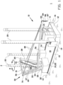
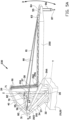
- FIG. 1 shows a self-elevating jack-up crane vessel 10 during sailing at sea 1.
- the crane vessel 10 is self-propelled, but alternatively the crane vessel 10 is towed by tugs.
- the crane vessel 10 comprises in this embodiment a rectangular hull 11 having a bow 12, a stern 13 a port side 14, a starboard side 15 and a large deck 18.
- the crane vessel 10 comprises a steering house 16, and in this example four upright legs 20 that are guided through jacking houses 19 having an internal drive to lower and raise each of the legs 20 in direction A as known per se to raise the hull 11 above the sea 1.
- all legs 20 are raised and extend with their top side high above the deck 18 and the bridge 17.
- the crane vessel 10 comprises a crane 30 according to a first embodiment of the invention above a crane foundation 22 on the hull 11.
- the crane foundation 22 coincides with one of the jacking houses 19, in this example above the rear starboard side jacking house 19.
- the crane vessel 10 with the crane 30 is designed to handle large wind turbine components, such as a tower 5, a nacelle 6 with a hub 7, and blades 8 to build an offshore wind turbine 4 at an offshore installation site.
- the wind turbine components may be shipped on the deck 18 to the installation site, but alternatively a feeder barge is used to ship the wind turbine components to the crane vessel 10.
- the crane vessel 10 On the installation site the crane vessel 10 is jacked up by lowering the legs 20 in direction A.
- the wind turbine components are installed aside the deck 18 by means of the crane 30.
- the offshore wind turbine 4 typically has a power of 8 Megawatt and require a lifting height above the waterline of 140 meters.
- Offshore wind turbines are continuously scaled up, wherein a power of 12 Megawatt is envisaged in the near future, and thereby a higher lifting height for the turbine components.
- the crane vessel 10 with the crane 30 can meet this increasing future demand.
- the invention is not limited to a jack-up crane vessel as shown in the figures.
- a jack-up rig with the crane 30 is considered a crane vessel according to the invention.
- the crane 30 may alternatively be installed on a semi-submersible crane vessel for performing the same kind of offshore hoisting operations as described above.
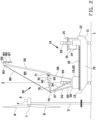
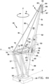
- the crane 30 is shown in more detail in figure 3 and figures 4A-4C .
- the crane 30 comprises a steel slewing crane base 31 around the leg 20 that is rotatingly mounted to the crane foundation 22 for rotation of the entire crane 30 in direction B around its vertical rotation axis Z, which in this example corresponds with the central axis of the leg 20 that extends through the jacking house 19.
- the leg 20 is removed for illustrative purposes only.
- the crane base 31 comprises a slew platform 32 and a rigid base frame 33 on the slew platform 32.
- the base frame 33 comprises a back structure having two upward back box girders 35 that are at their bottom end mounted to the back side of the slew platform 32 and that diverge upwardly away from each other and away from the vertical rotation axis Z.
- the upward back box girders 35 are at their top end connected with a transverse back box girder 36.
- the base frame 33 furthermore comprises two cross box girders 37 that are at their bottom end mounted to the front side of the slew platform 32 when considered in the direction of a horizontal axis Y and that diverge upwardly away from each other and away from the vertical axis Z and toward the upward back box girders 35.
- the cross box girders 37 and the transverse back box girder 36 together form a portal 34 of the base frame 33.
- the cross box girders 37 are at their top end connected with the respective upward back box girder 35, close to the transverse back box girder 36 to form rigid triangular frame configurations or A-frame configurations on both sides of the vertical axis Z.
- the portal 34 forms a back suspension or first suspension 70 of the crane base 31 at the upper back of the base frame 33, near the transverse back box girder 36.
- the crane base 31 comprises an upward front box girder 38 that is at its bottom end mounted to the front side of the slew platform 32.
- the upward front box girder 38 supports at its top end a transverse front box girder 39 that at its ends merges into two angled side box girders 40.
- the side box girders 40 are at their opposite end connected with the meeting ends of the upward back box girders 35 and the cross box girders 37 to form a rigid front suspension or second suspension 71 of the crane base 31 at the transverse front box girder 39.
- the crane 30 comprises a boom 50 that extends in a projection parallel to the vertical axis Z in the direction of the horizontal axis Y.
- the boom 50 comprises in this example a single, straight elongated distal boom section 51 with a boom tip 55.
- the distal boom section 51 is a latticed distal boom section 51.
- the lattice construction can be made from carbon fiber tubes, or from steel tubes.
- the distal boom section 51 merges via a boom splitter 52 into two straight, elongated proximal boom sections 53 that form a boom heel 56 at the bottom.
- the proximal boom sections 53 are box girder proximal boom sections 53.
- the proximal boom sections 53 have an elongated first free space 54 in between for passage of the upward front box girder 38 and encircling the leg 20 that extends vertically through the crane base 31.
- the boom splitter 52 is positioned to come between the two legs 20 at the starboard side of the crane vessel 10 when the boom 50 is in its lowered transport position. It is also possible to position the boom splitter 52 beyond both these legs 20 whereby both these legs 20 extends through the first free space 54.
- the proximal boom section can be a single proximal boom section with the boom heel. In that case the front upward box girder 38 can comprise two sections aside each other with the boom in between.
- the crane 30 comprises a steel boom spacer 60 that extends between the boom heel 56 and the crane base 31.
- the boom spacer 60 comprises two straight, elongated spacers 61 that extend spaced apart from each other between the respective proximal boom sections 53 and the first suspension 70.
- the spacers 61 are latticed spacers or box girder spacers.
- the spacers 61 each have a first end 65 that is connected with a transverse top box girder 62 that is rotatable connected with the first suspension 70 for rotation in direction D around a horizontal rotation axis X.
- the boom spacer 60 has two rotation points with the first suspension 70, that are spaced apart from each other in the direction of the horizontal rotation axis X.
- the spacers 61 each have an opposite second end 66 that merge under an angle C into the bottom ends of the proximal boom sections 52. In this example these are rigidly connected with each other, under a fixed angle C of about 90-130 degrees.
- the proximal boom sections 52 and the spacers 61 may alternatively be connected with each other by means of hinges with a horizontal rotation axis that extends parallel to the rotation axis X at the first suspension 70.
- the spacers 61 have an elongated second free space 64 in between that forms a continuation of the first free space 54 for passage of the front upward box girder 38 and the leg 20 that extends vertically through the crane base 31.
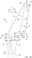
- the crane 30 comprises two elongated pendants 80 that extend between the first suspension 70 and the boom tip 55.
- the pendants 80 mutually converge toward the distal boom section 51 to form a substantial triangular configuration.
- the pendants 80 each comprise a cable or rope 81 that is in this example based on a synthetic fiber, for example an aramid or a high performance polyethylene (HPPE) (for example known under the name Dyneema ® ), or carbon.
- the pendants 80 comprise a first end 82 on the rope 81 that is rotatable connected with the first suspension 70 to rotate around a horizontal rotation axis that is parallel to, or coincides with the horizontal rotation axis X of the boom spacer 60.
- the two first ends 82 are spaced apart from each other at the first suspension 70 over a distance G that is larger than the largest width of the distal boom section 51, and preferably larger than the largest width of the entire boom 50.
- the distance G is also larger than the largest width of the slew platform 32 in that direction.
- the first ends 82 of the ropes 81 are in the proximity of their respective nearest rotation point of the spacers 61 to prevent the generation of bending moments in the transverse back box girder 37.
- the pendants 80 comprise a second end 83 on the rope 81 that is connected with the boom tip 55.
- the ropes 81 have a fixed material length between the first end 82 and second end 83 of the pendants 80.
- the ropes 81 may under this fixed material length stretch elastically due to a pulling force action on it.
- the pendants 80 mutually converge toward the boom tip 55 forming a triangular configuration.
- the pendants 80 mutually converge toward the boom tip 55 while crossing each other before the boom tip 55, giving effectively the same triangular configuration.
- the boom 50 In the operative position the boom 50 is loaded under a pressure force in its elongated direction while the pendants 80 are loaded under pure pulling forces, such that any side forces created by a load motion in sideward direction E, for example by a slightly swinging hoisted load or by any other external factor, are taken by the pendants 80 and transferred to the first suspension 70 where the first ends are spaced apart from each other over the distance G, which is forms the base of the triangle configuration of the pendants 80.
- This base is located high in the base frame 33 of the crane base 31.
- the pendants 80 give the boom tip 55 sideward stability against lateral bending of the boom 50 to prevent lateral buckling of the boom 50.
- the pendants 80 have their second ends 83 close to each other on the boom tip 55.
- the crane 30 comprises multiple hoisting sheaves 84 at the boom tip 55, a multi sheave hoisting block 87 and a load hoisting cable 86 with multiple windings there between for hoisting the load.
- the boom 50 has a length H between the boom tip 55 and the boom heel 56
- the boom spacer 60 has a length K between the boom heel 56 and the rotation axis X.
- the length K of the boom spacer 61 is 20-50% of the Length H of the boom 50.
- the crane 30 comprises a boom luffing installation 90 between the boom spacer 60 and the front suspension 71.
- the boom luffing installation 90 comprises a hoisting assembly 91 between the front suspension 71 and the boom heel 56.
- the boom 50 can by means of the boom luffing installation 90 be lifted and rotated around the horizontal rotation axis X between its lowered position as shown in figure 1 , wherein in this example it is supported by a boomrest 21 in front of the steering house 16, and its operational raised position for hoisting as shown in figure 2 .
- the boom 50 is luffed into the operational position, the entire boom 50, that is including the boom heel 56, is lifted vertically upwards by the boom spacer 60 while the tetrahedron configuration remains stable.
- the maximum lifting height of the crane 30 is extended when compared to a traditional boom that is at the boom heel directly rotatable connected with a crane base and raised by means of a luffing hoist tackle above the boom.
- the first suspension 70 in particular the horizontal rotation axis X of the boom 50, extends at about the same vertical height as the boom heel 56. That is, within 5 meters vertical height difference in the direction of the vertical rotation axis Z.
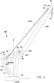
- FIGS 5A , 5B and 6 show a crane 230 according to a second embodiment of the invention on the jack-up house 19 of the jack-up crane vessel 10.
- the components of this crane 230 that correspond with the crane 30 according to the first embodiment are provided with the same reference numbers. Only the deviating components are discussed hereafter and are provided with reference numbers added with 200.
- the crane 230 comprises a single, straight, elongated boom 250 that extends in the projection parallel to the vertical axis Z in the direction of the horizontal axis Y.
- the boom 250 has the boom tip 55 at its distal end and a boom heel 256 at the bottom of the proximal end.
- the boom 250 is a latticed boom 250.
- the lattice construction can be made from steel tubes.
- the boom 250 is a single column, made of steel or carbon fiber.
- the crane comprises a steel boom spacer 260 that extends between the boom heel 256 and the crane base 31.
- the boom spacer 260 comprises two spacers 261 that are at a first end 265 rotatable connected with the first suspension 70 for rotation in direction D around the horizontal rotation axis.
- the spacers 261 converge from the first suspension 70 to the boom heel 256 where they are rigidly connected with at their second end 266.
- the spacers 261 are rigidly connected with the boom heel 256, under a fixed angle C of about 110-145 degrees.
- the boom heel 256 and the spacers 261 may alternatively be connected with each other by means of hinges with a horizontal rotation axis that extends parallel to the rotation axis X at the first suspension 70.
- the boom heel 256 Under the fixed angle C, the boom heel 256 extends in the operational, raised position as shown in figure 6 even above the first suspension 70 in the vertical direction parallel to the rotation axis Z. In this embodiment the boom heel 256 does not pass the upward front box girder 38. The boom heel 256 extends in both the lowered transport position and in the raised operational position in front of the front box girder 38 in the direction of the horizontal axis Y.
- the boom heel 56, 256 is raised by the boom luffing 90 having the hoisting assembly 91.
- the boom heel 56, 256 may be lifted by means of a hydraulic equivalent.
Landscapes
- Engineering & Computer Science (AREA)
- General Engineering & Computer Science (AREA)
- Mechanical Engineering (AREA)
- Civil Engineering (AREA)
- Structural Engineering (AREA)
- Jib Cranes (AREA)
Claims (15)
- Hubkranschiff (10) oder halbtauchfähiges Kranschiff, das einen Rumpf (11) mit einem Deck (18) und einen Kran (30) an dem Rumpf (11) für das Heben einer Last außerhalb des Decks (18) umfasst, wobei der Kran (30) eine Schwenkkranbasis (31), die in Bezug auf den Rumpf (11) um eine vertikale Drehachse (Z) gedreht werden kann, einen länglichen Ausleger (50, 250), der um eine horizontale Drehachse (X) in Bezug auf die Kranbasis (31) gedreht werden kann, wenigstens zwei Aufhängungsverbindungen (80) zwischen dem Ausleger (50, 250) und der Kranbasis (31), einen Auslegerabstandshalter (60, 260) zwischen dem Ausleger (50, 250) und der Kranbasis (31) und eine Auslegerwippinstallation (90) für das Antreiben einer Drehung des Auslegers (50, 250) um die horizontale Drehachse (X) zwischen einer gesenkten Transportposition und einer gehobenen Betriebsposition umfasst, wobei die Kranbasis (31) eine Schwenkplattform (32) und einen Basisrahmen (33) über der Schwenkplattform (32), der eine erste Aufhängung (70) der Kranbasis (31) für den Ausleger (50, 250) bildet, umfasst, wobei der Ausleger (50, 250) einen fernen Auslegerabschnitt (51) mit einem Ende (55) und einen nahen Auslegerabschnitt (53) mit einem Auslegerfuß (56, 256) umfasst, wobei die Aufhängungsverbindungen (80) ein erstes Ende (82), das mit der ersten Aufhängung (70) verbunden ist, und ein gegenüberliegendes zweites Ende (83), das mit dem fernen Auslegerabschnitt (51) verbunden ist, umfassen, wobei die Aufhängungsverbindungen (80) jeweils zu dem fernen Auslegerabschnitt (51) hin zusammenlaufen, wobei der Auslegerabstandshalter (60, 260) ein erstes Ende (65, 265), das drehbar mit der ersten Aufhängung (70) für eine Drehung um die horizontale Achse (X) verbunden ist, und ein gegenüberliegendes zweites Ende (66, 266), das von dem ersten Ende (65, 265) beabstandet und mit dem Auslegerfuß (56, 256) verbunden ist, um den Ausleger (50, 250) von der horizontalen Achse (X) beabstandet zu halten, aufweist und wobei sich in der Richtung der vertikalen Drehachse (Z) die erste Aufhängung (70) wenigstens in der gesenkten Transportposition des Auslegers (50, 250) über dem Auslegerfuß (56, 256) des Auslegers (50, 250) erstreckt.
- Kranschiff (10) nach Anspruch 1, wobei der Auslegerabstandshalter (60, 260) den Auslegerfuß (56, 256) von der horizontalen Drehachse (X) mit einer fixen Distanz beabstandet hält.
- Kranschiff (10) nach einem der vorstehenden Ansprüche, wobei sich in der Richtung der vertikalen Drehachse (Z) die erste Aufhängung (70) in der erhobenen Position des Auslegers (50, 250) auf ungefähr der gleichen Höhe erstreckt wie der Auslegerfuß (56, 256) des Auslegers.
- Kranschiff nach einem der vorstehenden Ansprüche, wobei sich in der erhobenen Position des Auslegers (50, 250) der Auslegerfuß (56, 256) in Bezug auf die erste Aufhängung (70) auf der gegenüberliegenden Seite der vertikalen Drehachse (Z) erstreckt.
- Kranschiff (10) nach einem der vorstehenden Ansprüche, wobei sich in einer Projektion parallel zu der horizontalen Drehachse (X) die horizontale Drehachse (X) in einer Richtung quer zu der Längsrichtung des Auslegers (50, 250) neben dem Ausleger (50, 250) erstreckt.
- Kranschiff (10) nach einem der vorstehenden Ansprüche, wobei der Auslegerabstandshalter (60, 260) eine Länge (K) zwischen der horizontalen Drehachse (X) und dem Auslegerfuß (56, 256) aufweist, die 20-50% der Länge (H) des Auslegers (50, 250) zwischen dem Auslegerende (55) und den Auslegerfuß (56, 256) ausmacht.
- Kranschiff (10) nach einem der vorstehenden Ansprüche, wobei der Auslegerabstandshalter (60, 260) mit einem Winkel (C) mit dem nahen Auslegerabstand (53) verbunden ist, wobei der Winkel (C) vorzugsweise ein fixer Winkel (C) ist, wobei der Winkel (C) vorzugsweise 90-145 Grad beträgt.
- Kranschiff (10) nach einem der vorstehenden Ansprüche, wobei die Aufhängungsverbindungen (80) die gleiche fixe Länge zwischen dem ersten Ende (82) und dem zweiten Ende (83) in der gesenkten Transportposition und in der gehobenen Betriebsposition des Auslegers (50, 250) aufweisen.
- Kranschiff (10) nach einem der vorstehenden Ansprüche, wobei die Aufhängungsverbindungen (80) ein Kabel oder Seil (81) zwischen dem ersten Ende (82) und dem zweiten Ende (83) umfassen, wobei das Kabel oder Seil (81) vorzugsweise aus einer Kunstfaser besteht.
- Kranschiff (10) nach einem der vorstehenden Ansprüche, wobei die ersten Enden (82) der Aufhängungsverbindungen (80) drehbar mit der ersten Aufhängung (70) verbunden sind.
- Kranschiff (10) nach einem der vorstehenden Ansprüche, wobei die ersten Enden (82) der Aufhängungsverbindungen (80) mit der ersten Aufhängung (70) mit einer Distanz (G) zueinander in der Richtung der horizontalen Drehachse (X) verbunden sind, die größer als die größte Breite des fernen Auslegerabschnitts (51) und /oder die größte Breite des Auslegers (50, 250) und/oder die größte Breite der Schwenkplattform (32) in dieser Richtung ist.
- Kranschiff (10) nach einem der vorstehenden Ansprüche, wobei der Auslegerabstandshalter (60, 260) zwei Abstandshalter (61, 261) umfasst, die sich voneinander beabstandet erstrecken, um dazwischen einen Durchgang (64) zu definieren, wobei sich die vertikale Drehachse (Z) durch den Durchgang (64) erstreckt.
- Kranschiff (10) nach einem der vorstehenden Ansprüche, wobei die Auslegerwippinstallation (90) einen linearen Antrieb zwischen der Kranbasis (31) und dem Auslegerfuß (56, 256) umfasst.
- Kranschiff (10) nach einem der vorstehenden Ansprüche, wobei die Kranbasis (31) eine zweite Aufhängung (71) auf der zu der ersten Aufhängung (70) gegenüberliegenden Seite in Bezug auf die vertikale Drehachse (Z) umfasst, wobei die Auslegerwippinstallation (90) eine Hubanordnung (91) zwischen der zweiten Aufhängung (71) und dem Auslegerfuß (56, 256) umfasst.
- Kranschiff (10) nach einem der vorstehenden Ansprüche, wobei der Basisrahmen (33) zwei nach oben gerichtete Kastenträger (35), die ein an der Schwenkplattform (32) montiertes unteres Ende aufweisen und voneinander beabstandet sind, und zwei quer angeordnete Kastenträger (37), die ein an der Schwenkplattform (32) montiertes unteres Ende aufweisen und voneinander beabstandet sind, umfassen, wobei die nach oben gerichteten Kastenträger (36) und die quer angeordneten Kastenträger (37) an ihren gegenüberliegenden oberen Enden in Paaren verbunden sind, um zwei dreieckige oder A-förmige Rahmenkonfigurationen auf gegenüberliegenden Seiten der vertikalen Drehachse (Z) zu bilden, wobei die erste Aufhängung (70) an der oberen Seite der dreieckigen oder A-förmigen Rahmenkonfigurationen angeordnet ist.
Applications Claiming Priority (2)
| Application Number | Priority Date | Filing Date | Title |
|---|---|---|---|
| NL2021651A NL2021651B1 (en) | 2018-09-17 | 2018-09-17 | Crane vessel |
| PCT/NL2019/050604 WO2020060394A1 (en) | 2018-09-17 | 2019-09-16 | Crane vessel |
Publications (3)
| Publication Number | Publication Date |
|---|---|
| EP3853166A1 EP3853166A1 (de) | 2021-07-28 |
| EP3853166C0 EP3853166C0 (de) | 2025-01-08 |
| EP3853166B1 true EP3853166B1 (de) | 2025-01-08 |
Family
ID=64902328
Family Applications (1)
| Application Number | Title | Priority Date | Filing Date |
|---|---|---|---|
| EP19828835.9A Active EP3853166B1 (de) | 2018-09-17 | 2019-09-16 | Kran-schiff |
Country Status (5)
| Country | Link |
|---|---|
| US (1) | US11525229B2 (de) |
| EP (1) | EP3853166B1 (de) |
| CN (1) | CN112912333B (de) |
| NL (1) | NL2021651B1 (de) |
| WO (1) | WO2020060394A1 (de) |
Families Citing this family (1)
| Publication number | Priority date | Publication date | Assignee | Title |
|---|---|---|---|---|
| CN117720023A (zh) * | 2023-11-24 | 2024-03-19 | 徐工集团工程机械股份有限公司建设机械分公司 | 一种吊臂结构、海上起重机及起吊方法 |
Family Cites Families (24)
| Publication number | Priority date | Publication date | Assignee | Title |
|---|---|---|---|---|
| GB1106325A (en) * | 1963-10-12 | 1968-03-13 | H C Stuelcken Sohn | Ship's loading derrick |
| DE1982859U (de) * | 1968-01-19 | 1968-04-04 | Atlas Mak Maschb G M B H | Schiffsladevorrichtung fuer schwere lasten. |
| DE2541065A1 (de) * | 1975-09-15 | 1977-03-17 | Hans Tax | Schwerlastdrehkran |
| SU650962A1 (ru) * | 1977-03-14 | 1979-03-05 | Kravchenko Gennadij V | Грузоподъемный плавучий кран |
| ES263032Y (es) * | 1982-02-08 | 1983-07-01 | "dispositivo de volquete y descarga de contenedores". | |
| US4653656A (en) * | 1984-07-30 | 1987-03-31 | Triplett James T | Double center luffing crane |
| JPH07157287A (ja) * | 1993-12-07 | 1995-06-20 | Shimauchi Jidosha Totsuki Seisakusho:Kk | クレーン |
| JP4299952B2 (ja) * | 2000-06-09 | 2009-07-22 | 株式会社加藤製作所 | 作業機械の折曲式アーム |
| US6826452B1 (en) * | 2002-03-29 | 2004-11-30 | The Penn State Research Foundation | Cable array robot for material handling |
| CN103231998B (zh) * | 2007-02-16 | 2016-03-23 | Itrec有限责任公司 | 一种具有提升起重机的船只 |
| CN101670986B (zh) * | 2009-09-28 | 2011-10-12 | 三一汽车制造有限公司 | 一种起重系统及一种移动式起重机 |
| CN203976265U (zh) * | 2012-06-21 | 2014-12-03 | 易东飞 | 新型吊臂平衡起重机 |
| CN102718158B (zh) * | 2012-06-27 | 2014-05-21 | 三一汽车起重机械有限公司 | 一种超起装置及起重机 |
| WO2014025253A1 (en) * | 2012-08-06 | 2014-02-13 | Itrec B.V. | Crane vessel |
| DK2956400T3 (en) * | 2013-02-18 | 2018-05-28 | High Wind N V | Apparatus and method for installing a wind turbine rotor blade |
| NL2011922C2 (en) * | 2013-12-09 | 2015-06-11 | Itrec Bv | Hoisting crane and method for refurbishing such a hoisting crane. |
| CN204824097U (zh) * | 2015-06-26 | 2015-12-02 | 江西四面体科技有限公司 | 新型安瓿拉丝灌封机 |
| CN204938798U (zh) * | 2015-09-14 | 2016-01-06 | 广东粤海汽车有限公司 | 可下倾角度的直臂式随车起重机 |
| NL2016616B1 (en) * | 2016-04-15 | 2017-11-15 | Itrec Bv | Hoisting crane, slew bearing, slew bearing assembly method, slew bearing maintenance method and vessel. |
| NL2017468B1 (en) * | 2016-09-15 | 2018-03-22 | Itrec Bv | Crane, vessel comprising such a crane, and a method for up-ending a longitudinal structure |
| NL2017776B1 (en) * | 2016-11-11 | 2018-05-24 | Itrec Bv | Marine crane vessel and method of operation |
| NL2017937B1 (en) * | 2016-12-06 | 2018-06-19 | Itrec Bv | A wave-induced motion compensating crane for use on an offshore vessel, vessel and load transferring method |
| EP4365122A3 (de) * | 2017-04-24 | 2024-08-07 | Itrec B.V. | Bewegungskompensierender kran zur verwendung auf einem offshore-schiff |
| NL2020389B1 (en) * | 2018-02-06 | 2019-08-14 | Itrec Bv | A crane |
-
2018
- 2018-09-17 NL NL2021651A patent/NL2021651B1/en active
-
2019
- 2019-09-16 US US17/276,655 patent/US11525229B2/en active Active
- 2019-09-16 CN CN201980069422.5A patent/CN112912333B/zh active Active
- 2019-09-16 EP EP19828835.9A patent/EP3853166B1/de active Active
- 2019-09-16 WO PCT/NL2019/050604 patent/WO2020060394A1/en not_active Ceased
Also Published As
| Publication number | Publication date |
|---|---|
| NL2021651B1 (en) | 2020-05-07 |
| EP3853166C0 (de) | 2025-01-08 |
| US11525229B2 (en) | 2022-12-13 |
| WO2020060394A1 (en) | 2020-03-26 |
| US20220042266A1 (en) | 2022-02-10 |
| EP3853166A1 (de) | 2021-07-28 |
| CN112912333B (zh) | 2023-04-11 |
| CN112912333A (zh) | 2021-06-04 |
Similar Documents
| Publication | Publication Date | Title |
|---|---|---|
| US10894701B2 (en) | Crane, vessel comprising such a crane, and a method for up-ending a longitudinal structure | |
| CN110114298B (zh) | 用在海上船上的对波浪引起的运动补偿的起重机、船及负载传递方法 | |
| CN112591632B (zh) | 用于在海上船上使用的升降起重机及操作方法 | |
| JP2019529286A5 (de) | ||
| CN106044585A (zh) | 一种多自由度补偿的海上风机整体吊装装置 | |
| EP4114781A1 (de) | Kranschiff zum heben einer offshore-windturbine oder komponente davon | |
| CN117337265A (zh) | 海上起重船舶和用于操作该海上起重船舶的方法 | |
| WO2020209712A1 (en) | Marine vessel having a crane and method of operation | |
| EP3853166B1 (de) | Kran-schiff | |
| US11952245B2 (en) | Hoisting crane for use on an offshore vessel and method of operation | |
| NL2024512B1 (en) | Offshore vessel crane | |
| NL2026416B1 (en) | Crane vessel with a crane for hoisting wind turbine components | |
| NL2028124B1 (en) | installation vessel | |
| NL2028741B1 (en) | upend crane and installation vessel | |
| KR20100008556U (ko) | 선박인양용 지브 크레인 | |
| NO20230738A1 (en) | An A-frame crane device | |
| NL2018375B1 (en) | Marine jack-up type crane vessel and methods of operation |
Legal Events
| Date | Code | Title | Description |
|---|---|---|---|
| STAA | Information on the status of an ep patent application or granted ep patent |
Free format text: STATUS: UNKNOWN |
|
| STAA | Information on the status of an ep patent application or granted ep patent |
Free format text: STATUS: THE INTERNATIONAL PUBLICATION HAS BEEN MADE |
|
| PUAI | Public reference made under article 153(3) epc to a published international application that has entered the european phase |
Free format text: ORIGINAL CODE: 0009012 |
|
| STAA | Information on the status of an ep patent application or granted ep patent |
Free format text: STATUS: REQUEST FOR EXAMINATION WAS MADE |
|
| 17P | Request for examination filed |
Effective date: 20210317 |
|
| AK | Designated contracting states |
Kind code of ref document: A1 Designated state(s): AL AT BE BG CH CY CZ DE DK EE ES FI FR GB GR HR HU IE IS IT LI LT LU LV MC MK MT NL NO PL PT RO RS SE SI SK SM TR |
|
| DAV | Request for validation of the european patent (deleted) | ||
| DAX | Request for extension of the european patent (deleted) | ||
| GRAP | Despatch of communication of intention to grant a patent |
Free format text: ORIGINAL CODE: EPIDOSNIGR1 |
|
| STAA | Information on the status of an ep patent application or granted ep patent |
Free format text: STATUS: GRANT OF PATENT IS INTENDED |
|
| INTG | Intention to grant announced |
Effective date: 20240820 |
|
| GRAS | Grant fee paid |
Free format text: ORIGINAL CODE: EPIDOSNIGR3 |
|
| GRAA | (expected) grant |
Free format text: ORIGINAL CODE: 0009210 |
|
| STAA | Information on the status of an ep patent application or granted ep patent |
Free format text: STATUS: THE PATENT HAS BEEN GRANTED |
|
| RAP1 | Party data changed (applicant data changed or rights of an application transferred) |
Owner name: PILING AND VIBRO EQUIPMENT B.V. |
|
| AK | Designated contracting states |
Kind code of ref document: B1 Designated state(s): AL AT BE BG CH CY CZ DE DK EE ES FI FR GB GR HR HU IE IS IT LI LT LU LV MC MK MT NL NO PL PT RO RS SE SI SK SM TR |
|
| REG | Reference to a national code |
Ref country code: GB Ref legal event code: FG4D |
|
| REG | Reference to a national code |
Ref country code: CH Ref legal event code: EP |
|
| REG | Reference to a national code |
Ref country code: DE Ref legal event code: R096 Ref document number: 602019064691 Country of ref document: DE |
|
| REG | Reference to a national code |
Ref country code: IE Ref legal event code: FG4D |
|
| U01 | Request for unitary effect filed |
Effective date: 20250123 |
|
| U07 | Unitary effect registered |
Designated state(s): AT BE BG DE DK EE FI FR IT LT LU LV MT NL PT RO SE SI Effective date: 20250129 |
|
| PG25 | Lapsed in a contracting state [announced via postgrant information from national office to epo] |
Ref country code: RS Free format text: LAPSE BECAUSE OF FAILURE TO SUBMIT A TRANSLATION OF THE DESCRIPTION OR TO PAY THE FEE WITHIN THE PRESCRIBED TIME-LIMIT Effective date: 20250408 |
|
| PG25 | Lapsed in a contracting state [announced via postgrant information from national office to epo] |
Ref country code: PL Free format text: LAPSE BECAUSE OF FAILURE TO SUBMIT A TRANSLATION OF THE DESCRIPTION OR TO PAY THE FEE WITHIN THE PRESCRIBED TIME-LIMIT Effective date: 20250108 |
|
| PG25 | Lapsed in a contracting state [announced via postgrant information from national office to epo] |
Ref country code: ES Free format text: LAPSE BECAUSE OF FAILURE TO SUBMIT A TRANSLATION OF THE DESCRIPTION OR TO PAY THE FEE WITHIN THE PRESCRIBED TIME-LIMIT Effective date: 20250108 |
|
| PG25 | Lapsed in a contracting state [announced via postgrant information from national office to epo] |
Ref country code: IS Free format text: LAPSE BECAUSE OF FAILURE TO SUBMIT A TRANSLATION OF THE DESCRIPTION OR TO PAY THE FEE WITHIN THE PRESCRIBED TIME-LIMIT Effective date: 20250508 |
|
| PG25 | Lapsed in a contracting state [announced via postgrant information from national office to epo] |
Ref country code: HR Free format text: LAPSE BECAUSE OF FAILURE TO SUBMIT A TRANSLATION OF THE DESCRIPTION OR TO PAY THE FEE WITHIN THE PRESCRIBED TIME-LIMIT Effective date: 20250108 |
|
| PG25 | Lapsed in a contracting state [announced via postgrant information from national office to epo] |
Ref country code: GR Free format text: LAPSE BECAUSE OF FAILURE TO SUBMIT A TRANSLATION OF THE DESCRIPTION OR TO PAY THE FEE WITHIN THE PRESCRIBED TIME-LIMIT Effective date: 20250409 |
|
| PG25 | Lapsed in a contracting state [announced via postgrant information from national office to epo] |
Ref country code: SM Free format text: LAPSE BECAUSE OF FAILURE TO SUBMIT A TRANSLATION OF THE DESCRIPTION OR TO PAY THE FEE WITHIN THE PRESCRIBED TIME-LIMIT Effective date: 20250108 |
|
| PGFP | Annual fee paid to national office [announced via postgrant information from national office to epo] |
Ref country code: NO Payment date: 20250923 Year of fee payment: 7 |
|
| PGFP | Annual fee paid to national office [announced via postgrant information from national office to epo] |
Ref country code: GB Payment date: 20250919 Year of fee payment: 7 |
|
| PG25 | Lapsed in a contracting state [announced via postgrant information from national office to epo] |
Ref country code: CZ Free format text: LAPSE BECAUSE OF FAILURE TO SUBMIT A TRANSLATION OF THE DESCRIPTION OR TO PAY THE FEE WITHIN THE PRESCRIBED TIME-LIMIT Effective date: 20250108 |
|
| PG25 | Lapsed in a contracting state [announced via postgrant information from national office to epo] |
Ref country code: SK Free format text: LAPSE BECAUSE OF FAILURE TO SUBMIT A TRANSLATION OF THE DESCRIPTION OR TO PAY THE FEE WITHIN THE PRESCRIBED TIME-LIMIT Effective date: 20250108 |
|
| U20 | Renewal fee for the european patent with unitary effect paid |
Year of fee payment: 7 Effective date: 20250924 |
|
| PLBE | No opposition filed within time limit |
Free format text: ORIGINAL CODE: 0009261 |
|
| STAA | Information on the status of an ep patent application or granted ep patent |
Free format text: STATUS: NO OPPOSITION FILED WITHIN TIME LIMIT |
|
| 26N | No opposition filed |
Effective date: 20251009 |