EP3851604A1 - Light element and method for manufacturing the same - Google Patents
Light element and method for manufacturing the same Download PDFInfo
- Publication number
- EP3851604A1 EP3851604A1 EP20217495.9A EP20217495A EP3851604A1 EP 3851604 A1 EP3851604 A1 EP 3851604A1 EP 20217495 A EP20217495 A EP 20217495A EP 3851604 A1 EP3851604 A1 EP 3851604A1
- Authority
- EP
- European Patent Office
- Prior art keywords
- sealing tape
- light element
- plates
- elastic sealing
- textile
- Prior art date
- Legal status (The legal status is an assumption and is not a legal conclusion. Google has not performed a legal analysis and makes no representation as to the accuracy of the status listed.)
- Granted
Links
- 238000000034 method Methods 0.000 title claims abstract description 16
- 238000004519 manufacturing process Methods 0.000 title claims abstract description 13
- 238000007789 sealing Methods 0.000 claims abstract description 152
- 239000004753 textile Substances 0.000 claims abstract description 26
- 230000005489 elastic deformation Effects 0.000 claims abstract description 4
- 239000002390 adhesive tape Substances 0.000 claims description 35
- 239000000853 adhesive Substances 0.000 claims description 14
- 230000001070 adhesive effect Effects 0.000 claims description 14
- 238000003780 insertion Methods 0.000 claims 1
- 230000037431 insertion Effects 0.000 claims 1
- 230000006835 compression Effects 0.000 description 16
- 238000007906 compression Methods 0.000 description 16
- 239000000463 material Substances 0.000 description 13
- 239000004744 fabric Substances 0.000 description 11
- 125000006850 spacer group Chemical group 0.000 description 10
- 230000000694 effects Effects 0.000 description 9
- 238000004026 adhesive bonding Methods 0.000 description 7
- 238000010276 construction Methods 0.000 description 5
- 238000007688 edging Methods 0.000 description 5
- XLYOFNOQVPJJNP-UHFFFAOYSA-N water Substances O XLYOFNOQVPJJNP-UHFFFAOYSA-N 0.000 description 5
- 238000009434 installation Methods 0.000 description 4
- 239000000835 fiber Substances 0.000 description 3
- 230000003287 optical effect Effects 0.000 description 3
- 229920003023 plastic Polymers 0.000 description 3
- 239000004417 polycarbonate Substances 0.000 description 3
- 229920000515 polycarbonate Polymers 0.000 description 3
- 230000001681 protective effect Effects 0.000 description 3
- 239000000758 substrate Substances 0.000 description 3
- 229910052782 aluminium Inorganic materials 0.000 description 2
- XAGFODPZIPBFFR-UHFFFAOYSA-N aluminium Chemical compound [Al] XAGFODPZIPBFFR-UHFFFAOYSA-N 0.000 description 2
- 230000008859 change Effects 0.000 description 2
- 229920001971 elastomer Polymers 0.000 description 2
- 239000011521 glass Substances 0.000 description 2
- 239000003365 glass fiber Substances 0.000 description 2
- 230000035515 penetration Effects 0.000 description 2
- 239000004033 plastic Substances 0.000 description 2
- 239000007787 solid Substances 0.000 description 2
- 238000003466 welding Methods 0.000 description 2
- 244000025254 Cannabis sativa Species 0.000 description 1
- 235000012766 Cannabis sativa ssp. sativa var. sativa Nutrition 0.000 description 1
- 235000012765 Cannabis sativa ssp. sativa var. spontanea Nutrition 0.000 description 1
- 230000004308 accommodation Effects 0.000 description 1
- 230000009471 action Effects 0.000 description 1
- 239000012790 adhesive layer Substances 0.000 description 1
- 230000005540 biological transmission Effects 0.000 description 1
- 235000009120 camo Nutrition 0.000 description 1
- 230000001413 cellular effect Effects 0.000 description 1
- 235000005607 chanvre indien Nutrition 0.000 description 1
- 239000012612 commercial material Substances 0.000 description 1
- 150000001875 compounds Chemical class 0.000 description 1
- 238000009833 condensation Methods 0.000 description 1
- 230000005494 condensation Effects 0.000 description 1
- 238000003851 corona treatment Methods 0.000 description 1
- 230000008878 coupling Effects 0.000 description 1
- 238000010168 coupling process Methods 0.000 description 1
- 238000005859 coupling reaction Methods 0.000 description 1
- 238000013016 damping Methods 0.000 description 1
- 230000001419 dependent effect Effects 0.000 description 1
- 239000013013 elastic material Substances 0.000 description 1
- 239000000806 elastomer Substances 0.000 description 1
- 230000002349 favourable effect Effects 0.000 description 1
- 239000006260 foam Substances 0.000 description 1
- 239000011487 hemp Substances 0.000 description 1
- 230000001771 impaired effect Effects 0.000 description 1
- 238000009413 insulation Methods 0.000 description 1
- 239000007788 liquid Substances 0.000 description 1
- 230000014759 maintenance of location Effects 0.000 description 1
- 238000002844 melting Methods 0.000 description 1
- 230000008018 melting Effects 0.000 description 1
- 229910052751 metal Inorganic materials 0.000 description 1
- 239000002184 metal Substances 0.000 description 1
- 239000004745 nonwoven fabric Substances 0.000 description 1
- 235000011837 pasties Nutrition 0.000 description 1
- 230000000149 penetrating effect Effects 0.000 description 1
- 238000009832 plasma treatment Methods 0.000 description 1
- 229920003229 poly(methyl methacrylate) Polymers 0.000 description 1
- 229920000139 polyethylene terephthalate Polymers 0.000 description 1
- 239000005020 polyethylene terephthalate Substances 0.000 description 1
- 239000004926 polymethyl methacrylate Substances 0.000 description 1
- 229920000915 polyvinyl chloride Polymers 0.000 description 1
- 239000004800 polyvinyl chloride Substances 0.000 description 1
- 238000002203 pretreatment Methods 0.000 description 1
- 230000008569 process Effects 0.000 description 1
- 230000005855 radiation Effects 0.000 description 1
- 238000011084 recovery Methods 0.000 description 1
- 230000002040 relaxant effect Effects 0.000 description 1
- 239000000565 sealant Substances 0.000 description 1
- 239000003566 sealing material Substances 0.000 description 1
- 239000011343 solid material Substances 0.000 description 1
- 238000003860 storage Methods 0.000 description 1
- 229920003051 synthetic elastomer Polymers 0.000 description 1
- 239000002699 waste material Substances 0.000 description 1
- 239000002759 woven fabric Substances 0.000 description 1
Images


Classifications
-
- E—FIXED CONSTRUCTIONS
- E04—BUILDING
- E04C—STRUCTURAL ELEMENTS; BUILDING MATERIALS
- E04C2/00—Building elements of relatively thin form for the construction of parts of buildings, e.g. sheet materials, slabs, or panels
- E04C2/02—Building elements of relatively thin form for the construction of parts of buildings, e.g. sheet materials, slabs, or panels characterised by specified materials
- E04C2/10—Building elements of relatively thin form for the construction of parts of buildings, e.g. sheet materials, slabs, or panels characterised by specified materials of wood, fibres, chips, vegetable stems, or the like; of plastics; of foamed products
- E04C2/24—Building elements of relatively thin form for the construction of parts of buildings, e.g. sheet materials, slabs, or panels characterised by specified materials of wood, fibres, chips, vegetable stems, or the like; of plastics; of foamed products laminated and composed of materials covered by two or more of groups E04C2/12, E04C2/16, E04C2/20
-
- E—FIXED CONSTRUCTIONS
- E04—BUILDING
- E04C—STRUCTURAL ELEMENTS; BUILDING MATERIALS
- E04C1/00—Building elements of block or other shape for the construction of parts of buildings
- E04C1/42—Building elements of block or other shape for the construction of parts of buildings of glass or other transparent material
-
- E—FIXED CONSTRUCTIONS
- E04—BUILDING
- E04C—STRUCTURAL ELEMENTS; BUILDING MATERIALS
- E04C2/00—Building elements of relatively thin form for the construction of parts of buildings, e.g. sheet materials, slabs, or panels
- E04C2/54—Slab-like translucent elements
- E04C2/543—Hollow multi-walled panels with integrated webs
Landscapes
- Engineering & Computer Science (AREA)
- Architecture (AREA)
- Civil Engineering (AREA)
- Structural Engineering (AREA)
- Life Sciences & Earth Sciences (AREA)
- Wood Science & Technology (AREA)
- Building Environments (AREA)
- Arrangement Of Elements, Cooling, Sealing, Or The Like Of Lighting Devices (AREA)
- Securing Of Glass Panes Or The Like (AREA)
Abstract
Die Erfindung betrifft ein Lichtelement sowie ein Verfahren zu dessen Herstellung. Das Lichtelement (10) mindestens eine erste (1) und eine zweite (2) Platte auf, die lichtdurchlässig sind, wobei die beiden Platten (1, 2) parallel zueinander angeordnet sind und ein flächenförmiges Textil (3) zwischen ihnen angeordnet ist. Ein elastisches Dichtband (4), ist entlang der Ränder (R) der Platten zwischen den Platten (1, 2) angeordnet, wobei das elastische Dichtband (4) die Platten (1, 2) beabstandet, um einen abgedichteten Hohlraum (H) zu bilden, in welchem das flächenförmige Textil (3) angeordnet ist. Dabei stellt sich, bei einem horizontal angeordneten Lichtelement (10) bei Belastung des elastischen Dichtbandes (4) nur mit einer Gewichtskraft der oberhalb angeordneten Platte(n) (2), durch eine elastische Verformung des elastischen Dichtbandes (4) ein erster Abstand zwischen der unterhalb und der oberhalb angeordneten Platte(n) (2) ein, der größer ist als eine Dicke des flächenförmigen Textils (3).The invention relates to a light element and a method for its production. The light element (10) has at least a first (1) and a second (2) plate which are translucent, the two plates (1, 2) being arranged parallel to one another and a sheet-like textile (3) being arranged between them. An elastic sealing band (4) is arranged along the edges (R) of the panels between the panels (1, 2), the elastic sealing band (4) spacing the panels (1, 2) to form a sealed cavity (H) form, in which the sheet-like textile (3) is arranged. In this case, with a horizontally arranged light element (10) when the elastic sealing band (4) is loaded only with a weight force of the plate (s) (2) arranged above, an elastic deformation of the elastic sealing band (4) results in a first distance between the below and the plate (s) (2) arranged above, which is greater than a thickness of the sheet-like textile (3).
Description
Die Erfindung betrifft ein Lichtelement mit mindestens zwei lichtdurchlässigen Platten, zwischen denen sich ein flächenförmiges Textil befindet und ein Verfahren zur Herstellung dieses Lichtelements.The invention relates to a light element with at least two translucent plates, between which there is a flat textile, and a method for producing this light element.
Derartige Lichtelemente mit Platten aus transparentem Kunststoffmaterial werden in großem Umfang in bzw. auf Dächern von z.B. Werkhallen, Fabrikgebäuden aber auch Bürogebäuden für die Belichtung benötigt und eingesetzt. Lichtelemente können jedoch nicht nur auf Dächern, sondern auch z.B. an Wänden eines Gebäudes oder auf freistehenden Trägern vorgesehen sein.Such light elements with plates made of transparent plastic material are required and used to a large extent in or on the roofs of e.g. factory halls, factory buildings and also office buildings for lighting. However, lighting elements can be provided not only on roofs, but also, for example, on the walls of a building or on free-standing supports.
Dabei sind verschiedene Formen der Lichtelemente bekannt. So beispielsweise eine Plattenform, bei der sich die Platten im Wesentlichen in einer Ebene erstrecken und sogenannte "Lichtbänder" bilden. Ein weiteres Beispiel ist eine Kuppelform, wobei sich die Platten im Wesentlichen gekrümmt erstrecken und sogenannte "Lichtkuppeln" formen. Die Platten können auch in einem Winkel zueinander vorgesehen sein und somit ein sogenanntes "Sattel-Lichtband" bilden. Lichtdurchlässige Platten sind üblicherweise als Hohlkammerelemente, wie extrudierte Stegplatten, z.B. Doppelstegplatten, ausgebildet.Different shapes of the light elements are known. For example, a plate shape in which the plates extend essentially in one plane and form so-called "light bands". Another example is a dome shape, wherein the plates extend essentially curved and form so-called "light domes". The plates can also be provided at an angle to one another and thus form a so-called "saddle light band". Translucent sheets are usually designed as hollow-chamber elements, such as extruded multi-wall sheets, e.g. double-walled sheets.
Die Beleuchtung in Innenräumen, z.B. mittels Lichtelementen, soll nach DIN 5034 blendbegrenzt sein. Es ist daher bekannt opalisierten Kunststoff für die lichtdurchlässigen Platten einzusetzen, der allerdings einen unerwünschten Lichtverlust mit sich bringt. Da zudem nach DIN 4102, Teil 7 ein Herabfallen von Elementen von Oberlichtkonstruktionen im Falle eines Feuers verhindert werden muss, wird in der
Das gewebeartige Material wird dabei in der
Um für die Oberlichtkonstruktion eine gleichbleibende Lichtdurchlässigkeit zu gewährleisten ist es erforderlich, den Hohlraum gegen das Eindringen von Wasser zu schützen, um die Beeinträchtigung der optischen Eigenschaften des Lichtelements durch z.B. Kondensation oder eindringendes (Stau-)Wasser zu verhindern. In der
Aufgabe der Erfindung ist also, ein Lichtelement sowie ein Verfahren zu seiner Herstellung bereitzustellen, welches einfach herstellbar ist und über die Lebensdauer des Lichtelements die Dichtigkeit zu gewährleisten.The object of the invention is therefore to provide a light element and a method for its production which is easy to produce and to ensure tightness over the service life of the light element.
Diese Aufgabe wird gemäß der Erfindung mit dem erfindungsgemäß hergestellten Lichtelement nach den Merkmalen des Anspruchs 1 dadurch gelöst, dass ein elastisches Dichtband vorgesehen ist, das entlang von Rändern der Platten des Lichtelements zwischen diesen Platten angeordnet ist. Bei dem erfindungsgemäßen Lichtelement wird der Abstand der wenigstens zwei Platten des Lichtelements durch das zwischen diesen Platten angeordnete elastische Dichtband eingestellt. Ein zwischen den jeweiligen Platten angeordnetes flächenförmiges Textil ist dabei dünner als der sich einstellende Abstand zwischen den Platten. Die Elastizität des Dichtbands ist dabei so gewählt, dass zumindest die bei horizontaler Anordnung des Lichtelements sich ergebende Gewichtskraft der darüber angeordneten Platten lediglich eine Kompression des Dichtbands bewirkt, welche zu einem Abstand zwischen den beiden Platten führt, der größer ist als die Dicke des flächenförmigen Textils. Damit ist gewährleistet, dass unabhängig von der Lage des Einbaus, sofern nicht durch Halterungen o. ä. zusätzliche Kräfte auftreten, welche die wenigstens zwei Platten aufeinander zu bewegen, die beiden Platten, welche benachbart zu dem flächenförmige Textil angeordnet sind, voneinander beabstandet sind und so eine freie Verfügbarkeit des dazwischen angeordneten flächenförmigen Textils ermöglichen. Wird die Anordnung aus zumindest zwei ein Lichtelement bildenden Platten in eine Halterung, beispielsweise ein U-förmiges Profil eingesetzt, so wird dadurch sichergestellt, dass die Platten in Anlage an den Schenkeln des U-förmigen Profils gehalten werden. Damit wird für das montierte Element der Abstand, der sich zwischen den beiden Platten einstellt, in diesem Fall durch das Profil eingestellt. Ähnliches gilt für Verschraubungen, die ebenfalls die Platten aufeinander zu bewegen.This object is achieved according to the invention with the light element produced according to the invention according to the features of
Durch den erfindungsgemäßen Gegenstand des Anspruchs 1 ist mit einfachen Mitteln ein Lichtelement erzielbar, das durch einen Abstand bildende Funktion des Dichtbandes ein Hohlraum zur klemmfreien Aufnahme des flächenförmigen Textils bereitgestellt wird, wobei das Dichtband gleichzeitig in der Lage ist den zwischen den Platten entstehenden Hohlraum abzudichten. Mit anderen Worten kann ein elastisches Dichtband als abdichtender Abstandshalter genutzt werden und so insbesondere die separate Verwendung von Abstandshalter mit zusätzlichem Dichtmittel vermieden werden. Durch die Elastizität bzw. elastische Verformbarkeit des Dichtbandes ist es möglich, dieses definiert zu verformen, um eine Dichtfunktion zu gewährleisten bzw. gegenüber den aus dem Stand der Technik bekannten Lösungen zu verbessern, während das Dichtband dabei auf eine definierte Dicke einstellbar ist, wodurch eine definierte Höhe des Hohlraums erzielt werden kann.By the subject matter of
Das erfindungsgemäße Lichtelement hat einen vereinfachten Aufbau, reduzierten Fertigungsaufwand und somit Fertigungskosten und verbessert die Handhabbarkeit des Lichtelements, da ein in sich abdichtender, elastischer Abstandshalter verwendet wird. Diese und weitere Vorteile werden im Beschreibungsteil näher erläutert.The light element according to the invention has a simplified structure, reduced production effort and thus production costs and improves the manageability of the light element, since an elastic spacer that seals itself is used. These and other advantages are explained in more detail in the description section.
Es ist vorteilhaft, wenn eine Seite des elastischen Dichtbands wenigstens abschnittsweise klebend mit einer der Platten verbunden ist. Das Dichtband kann somit auf dem Körper platziert werden und ist so in fester relativer Position bezüglich dieser Platte fixiert. Dies verbessert die Handhabbarkeit. Außerdem kann die Dichtwirkung des Dichtbandes durch das Kleben verbessert werden. Bei einer elastischen Verformung des Dichtbandes kann der Kleber einer Rückstellung des Dichtbandes entgegenwirken. Die zur Aufrechterhaltung der elastischen Verformung des Dichtbandes nötigen Kräfte können daher reduziert werden.It is advantageous if one side of the elastic sealing tape is at least partially adhesively connected to one of the plates. The sealing tape can thus be placed on the body and is thus fixed in a fixed relative position with respect to this plate. This improves the operability. In addition, the sealing effect of the sealing tape can be improved by gluing. In the event of elastic deformation of the sealing tape, the adhesive can counteract a recovery of the sealing tape. The forces required to maintain the elastic deformation of the sealing tape can therefore be reduced.
Es ist weiterhin vorteilhaft, wenn ein doppelseitig klebendes elastisches Dichtband verwendet wird, also zwei Seiten des elastischen Dichtbands wenigstens abschnittsweise klebend mit beiden Platten verbunden sind. Zusätzlich zu den bereits beschriebenen Vorteilen ist es mit beidseitiger Klebung möglich, das Lichtelement beispielsweise an einer Stirnseite besonders gut und haltbar abzudichten, dass auch bei dem Vorhandensein von Stauwasser bei Regen das Eindringen dieses zuverlässig verhindert werden kann. Außerdem wird durch ein beidseitiges verkleben die Handhabung bis zur endgültigen Montage des Lichtelements verbessert. Die Platten sind relativ zueinander durch das Verkleben des Dichtbands fixiert und ein Verschieben der Platten zueinander beispielsweise beim Transport zur Baustelle und während der Montage wird verhindert.It is also advantageous if a double-sided adhesive elastic sealing tape is used, that is to say two sides of the elastic sealing tape are at least partially adhesively connected to both plates. In addition to the advantages already described, it is possible with double-sided bonding to seal the light element particularly well and durably, for example on one end face, so that the penetration can be reliably prevented even if there is backwater when it rains. In addition, gluing on both sides improves handling up to the final assembly of the light element. The panels are fixed relative to one another by gluing the sealing tape and the panels are prevented from shifting in relation to one another, for example during transport to the construction site and during assembly.
Es ist weiterhin vorteilhaft, wenn das gesamte elastische Dichtband, das zwischen 2 benachbarten Platten des Lichtelements angeordnet ist mehrere Dichtbandabschnitte umfasst, die zwischen den Platten angeordnet sind, wobei zwischen den mehreren Dichtbandabschnitten sich ergebende Stoßstellen dichtend gefügt, insbesondere geklebt sind. Dadurch ist es möglich, das Dichtband aus stückweise aufgebrachter Endlosware bzw. Meterware zusammenzusetzen und somit handelsübliche bzw. Standardware zu verwenden. Dies senkt die Kosten, während quasi beliebige Formen des Dichtbandes mit einem Minimum an Warenvielfalt erzielbar sind. So können beispielsweise gerade Dichtbandabschnitte gewinkelt zueinander vorgesehen werden, sodass ein beispielsweise rechteckiges Dichtband erzielbar ist. Durch Verkleben der Stoßstellen, also aneinander angrenzende Enden der Einzelbänder, kann eine Dichtigkeit des Klebebandes gewährleistet werden.It is furthermore advantageous if the entire elastic sealing tape, which is arranged between 2 adjacent plates of the light element, comprises a plurality of sealing tape sections, which are arranged between the plates, wherein between the several Joints resulting from sealing tape sections are sealingly joined, in particular glued. This makes it possible to assemble the sealing tape from piecewise applied endless goods or piece goods and thus to use commercially available or standard goods. This lowers the costs, while virtually any shape of the sealing tape can be achieved with a minimum of variety of goods. For example, straight sealing tape sections can be provided at an angle to one another, so that a, for example, rectangular sealing tape can be achieved. By gluing the joints, that is to say ends of the individual tapes that are adjacent to one another, the adhesive tape can be guaranteed to be sealed.
Es ist weiterhin vorteilhaft, wenn zusätzlich zu dem elastischen Dichtband ein Klebeband um den Rand der wenigstens zwei aufeinander angeordneten Platten angeordnet wird, so dass das zwischen diesen Platten angeordnete Dichtband bis zum Einbauzeitpunkt der Elemente komprimiert bleibt. Durch Kompression des Dichtbandes wird die Dichtwirkung verbessert. Außerdem kann die Neigung des flächenförmigen Textils zum Faltenwurf durch die so verringerte Höhe des Hohlraums reduziert werden, was die Handhabbarkeit des Lichtelements verbessert. Durch Verwenden eines Klebebands zur Erzeugung der Kompression kann der Aufwand reduziert werden und ein Kantenschutz des Lichtelements erreicht werden. Gleichzeitig kann mittels des Klebebandes auf einer Außenseite des Lichtelements eine Schutzfolie, wie eine Hagelschutzfolie angebracht werden. Durch Verwenden des Klebebandes, also eines flexiblen Mittels, zur Erzeugung einer Dichtbandkompression kann das Dichtband durch eine weitere Klemmvorrichtung zur Montage auf ein finales Abstandsmaß komprimiert werden, ohne dass das Klebeband vorher entfernt werden muss. Es ist somit zu jeder Zeit eine ausreichende Dichtwirkung gewährleistet. Wird das Dichtband direkt in Anschluss an die Herstellung des Lichtelements durch Anbringen des Klebebandes komprimiert, kann das Lichtelement außerdem in beliebiger Lage gehandhabt werden, ohne dass die Platten verrutschen. Das Klebeband dient also auch als Transport- und Lagesicherung.It is also advantageous if, in addition to the elastic sealing tape, an adhesive tape is arranged around the edge of the at least two panels arranged on top of one another, so that the sealing tape arranged between these panels remains compressed until the elements are installed. The sealing effect is improved by compressing the sealing tape. In addition, the tendency of the sheet-like textile to fold in folds can be reduced by the height of the cavity being reduced in this way, which improves the manageability of the light element. By using an adhesive tape to generate the compression, the effort can be reduced and edge protection of the light element can be achieved. At the same time, a protective film, such as a hail protection film, can be attached to an outside of the light element by means of the adhesive tape. By using the adhesive tape, that is to say a flexible means, to produce a sealing tape compression, the sealing tape can be compressed to a final distance dimension by a further clamping device for assembly without the adhesive tape having to be removed beforehand. A sufficient sealing effect is thus guaranteed at all times. If the sealing tape is compressed by attaching the adhesive tape directly after the production of the light element, the light element can also be handled in any position without the panels slipping. The adhesive tape also serves as a transport and positional security device.
Im Folgenden wird die Erfindung anhand der in den Figuren dargestellten Ausführungsbeispiele und weiterer, nicht dargestellter Ausführungsbeispiele beschrieben und näher erläutert.In the following, the invention is described and explained in more detail on the basis of the exemplary embodiments shown in the figures and further exemplary embodiments that are not shown.
Dabei zeigt
-
Fig. 1a einen Querschnitt eines Lichtelements eines ersten Ausführungsbeispiel ohne zusätzliche Kompression mittels Klebeband. -
Fig. 1b zeigt den Querschnitt des Lichtelements des ersten Ausführungsbeispiels mit Vorkompression. -
Fig. 2 eine perspektivische Ansicht eines Lichtelements in einem Zwischenschritt der Herstellung ohne oberen Körper. -
Fig. 3a eine Detailansicht in Draufsicht des Lichtelement in einem Zwischenschritt der Herstellung ohne oberen Körper mit Dichtungsstoß. -
Fig. 3b die Detailansicht mit einem anderen Dichtungsstoß. -
Fig. 3c die Detailansicht mit einem weiteren Dichtungsstoß. -
Fig. 4 einen Querschnitt eines Lichtelement eines zweiten Ausführungsbeispiels mit Kompression durch Montage. -
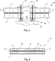
Fig. 5 einen Querschnitt eines Lichtelement eines dritten Ausführungsbeispiels mit Kompression durch Montage. -
Fig. 6 einen Querschnitt eines Lichtelements eines vierten Ausführungsbeispiels mit mehreren Hohlräumen. -
Fig. 7 einen Querschnitt eines Lichtelements eines fünften Ausführungsbeispiels nach Montage. -
Fig. 8 einen Längsschnitt eines Lichtelements eines sechsten Ausführungsbeispiels nach Montage. -
Fig. 9 einen Längsschnitt eines Lichtelements eines siebten Ausführungsbeispiels nach Montage.
-
Fig. 1a a cross section of a light element of a first embodiment without additional compression by means of adhesive tape. -
Figure 1b shows the cross section of the light element of the first embodiment with precompression. -
Fig. 2 a perspective view of a light element in an intermediate step of manufacture without an upper body. -
Fig. 3a a detailed view in plan view of the light element in an intermediate step of manufacture without an upper body with a sealing joint. -
Figure 3b the detailed view with a different seal joint. -
Figure 3c the detailed view with another seal joint. -
Fig. 4 a cross section of a light element of a second embodiment with compression by assembly. -
Fig. 5 a cross section of a light element of a third embodiment with compression by assembly. -
Fig. 6 a cross section of a light element of a fourth embodiment with a plurality of cavities. -
Fig. 7 a cross section of a light element of a fifth embodiment after assembly. -
Fig. 8 a longitudinal section of a light element of a sixth embodiment after assembly. -
Fig. 9 a longitudinal section of a light element of a seventh embodiment after assembly.
Es ist zu beachten, dass für die nachfolgenden Ausführungen davon ausgegangen wird, dass das Lichtelement aus lediglich 2 Platten besteht. Das Gesagte gilt analog für den Fall, dass das Lichtelement mehr als 2 Platten umfasst.It should be noted that for the following explanations it is assumed that the light element consists of only 2 panels. What has been said applies analogously to the case that the light element comprises more than 2 plates.
Zwischen den zwei Doppelstegplatten 1, 2 des Beispiels erzeugt ein beabstandendes elastisches Dichtband 4 einen Hohlraum H. In diesem ist ein flächenförmiges Textil 3 angeordnet. Dieses dient abgesehen von einer Sicherung gegen ein Herabfallen von Teilen im Falle eines Brandes in bekannter Weise dazu, von außen, in
Für diesen Zweck eignet sich eine Vielzahl von flächenförmigen Textilien 3. Als besonders geeignet haben sich Vliese und bevorzugt Gewebe herausgestellt, die z.B. aus Glasfasern hergestellt werden. Diese weisen neben guter optischer Eigenschaften auch eine vorteilhafte Hitzebeständigkeit auf, so dass eine Brandsicherheit des Lichtelements 10 gewährleistet werden kann. Es hat sich auch als vorteilhaft erwiesen, das flächenförmige Textil 3, im Folgenden auch das Gewebe 3, zusätzlich mechanisch zu verstärken, z.B. mit Metallfasern, um die Durchschlagfestigkeit weiter zu erhöhen. Wird z.B. das Lichtelement 10 durchdrungen und bricht die obere Platte 2 lokal ein, kann das Gewebe 3 eine vergleichsweise höhere Last tragen bzw. diese auf eine größere Wirkfläche verteilen und so die Flächenbelastung der darunterliegenden Platte 1 verringern.A large number of sheet-
Neben der Verwendung von Glasfasern ist insbesondere unter ökonomischen Gesichtspunkten auch die Verwendung oder Beimischung verschiedener Naturfasern, wie gebleichten Hanf- oder Leinenfasern empfehlenswert, da diese einfach zu verarbeiten sind und gute Dämmeigenschaften aufweisen.In addition to the use of glass fibers, the use or admixture of various natural fibers, such as bleached hemp or linen fibers, is also recommended, especially from an economic point of view, since these are easy to process and have good insulating properties.
Wie bereits erwähnt wird bzw. ist das flächenförmige Textil 3 in den Hohlraum H eingelegt. Die Höhe des Hohlraums bei noch nicht montiertem Lichtelement ist dabei 50 % bis 100 % größer als die Dicke des noch zu beschreibenden elastischen Dichtbands 4. dies erlaubt eine weitere Kompression des elastischen Dichtbands 4 bei der Montage des Lichtelement auf dem Gebäude.As already mentioned, the sheet-
Um die aufgabengemäße Abdichtung bei gleichzeitigem Halten des Abstands mit geringem Aufwand zu erzielen, ist das elastische Dichtband 4 als im Wesentlichen feste Masse vorgesehen, im Gegensatz zu Dichtmitteln, die flüssig oder pastös aufgebracht werden. Dies erlaubt es, in noch näher zu beschreibender Weise, das Dichtband 4 elastisch zu verformen bzw. zu komprimieren und somit den Aufbau von dichtend wirkender Flächenpressung bei Beaufschlagung der Platten 1, 2 und mittels dieser des Dichtbandes 4 mit Druckkraft. Das Lichtelement mit einem entsprechend mittels eines Klebebandes 5 komprimierten Dichtbandes 4 ist in
Das Dichtband 4 ist, wie in
Es ist darauf zu achten, dass die verklebte(n) oder verschweißte(n) Stoßstelle(n) eine ausreichende Zugbelastbarkeit in der Dichtbandebene, also eine ausreichende Belastbarkeit bei Querdehnung des Dichtbandes 4 aufweist, damit es beim Komprimieren und damit einer Verformung des Dichtbandes 4 nicht zum Ablösen oder Reißen der Stoßstelle kommt. Dies kann bspw. durch geeignete Kleberauswahl, hohe Klebermenge oder gleichmäßiges Verschweißen erreicht werden. Es wird bevorzugt die Kaltnahtfestigkeit mindestens so hoch zu wählen wie die Zugfestigkeit des Dichtbandmaterials.It must be ensured that the glued or welded joint (s) has sufficient tensile strength in the sealing tape plane, i.e. sufficient loading capacity when the sealing
Das Dichtband 4 muss, wie erwähnt, elastisch sein, damit es definiert komprimiert werden kann und dichtend wirkt. Dazu haben sich insbesondere (gummi)elastische Werkstoffe als vorteilhaft erwiesen. Besonders bevorzugt wird ein Schaumstoff oder zelliger Weichkunststoff eingesetzt. Hier ist jedoch darauf zu achten, dass eine Porosität des Materials ausreichend klein ist, um das Kriechen von Wasser entlang einer Grenzfläche zwischen Doppelstegplatte 1, 2 und Dichtband 4, sowie das Aufsaugen von Wasser in das Material zu verhindern. Diesen Anforderungen genügt z.B. ein Elastomer, wie ein an sich bekannter (synthetischer) Kautschuk.As mentioned, the sealing
Das Dichtband 4 wird bei dem in
Die bisherigen Ausführungen beziehen sich auf eine Anordnung, bei der das Dichtband 4 lediglich an den Rändern von 2 parallel zueinander angeordneten Platten 1, 2 angeordnet ist. Es können aber weitere Dichtbandabschnitte zur Unterteilung der gesamten Fläche vorgesehen sein. Auch die einschlägige Ausführung, bei der Stege im Inneren des am Rand der plattenumlaufenden Dichtbands 4 vorgesehen sind, sind denkbar. Solche Stege sind insbesondere dann vorzusehen, wenn eine Verschraubung zur Fixierung des Lichtelements im Inneren der Fläche vorgesehen werden muss.The previous statements relate to an arrangement in which the sealing
Im Folgenden wird ein Verfahren beschrieben, mit dem das Lichtelement 10 hergestellt werden kann.In the following, a method is described with which the
Zunächst wird, wie in
Durch diese Verklebung kann die Dichtwirkung weiter erhöht werden. Es ist dadurch aber auch möglich, das Dichtband 4 auf der unteren Platte 1 zu fixieren, so dass dieses eine bestimmte Lage hält indem es nicht mehr verrutscht. Es ist zu beachten, dass bei Verwendung einer Platte 1, 2 aus Polykarbonat ein entsprechend verträglicher Kleber zu verwenden ist.The sealing effect can be further increased by this bonding. It is thereby also possible to fix the sealing
Unter "Kleben" wird im Sinne der Erfindung auch jede andere, geeignete Form der adhäsiven Verbindung verstanden. So kann neben dem Auftrag von Kleber auch die Oberfläche des Dichtbandes 4 thermisch oder chemisch aktiviert, z.B. angeschmolzen oder gelöst, werden, um eine adhäsive Verbindung mit einer Platte 1, 2 zu erreichen. Es sind auch Vorbehandlungen der Platte 1, 2 und/oder des Dichtbandes 4 denkbar, die die Benetzbarkeit erhöhen, wie z.B. mittels Plasmabehandlung bzw. Corona-Behandlung.In the context of the invention, “gluing” is also understood to mean any other suitable form of adhesive connection. In addition to the application of adhesive, the surface of the sealing
Das Dichtband 4 des Lichtelements 10 wird bevorzugt allseitig beabstandet zu Rändern R der Platten 1, 2 vorgesehen, wie in
In einem nächsten Schritt wird das Gewebe 3 in eine durch das Dichtband 4 begrenzte Fläche F auf der unteren Doppelstegplatte 1 eingelegt, wobei die Fläche F mit dem Hohlraum H des fertigen Lichtelements 10 korrespondiert. Bevorzugt ist das Gewebe 3 dabei so bemessen, dass es einen allseitigen Abstand von 0.5 bis 2 mm zum Dichtband 4 einnimmt, damit das Gewebe 3 bei der Querausdehnung des Dichtbandes 4 durch Kompression nicht eingeklemmt wird. Wird jedoch ein Dichtband 4 verwendet, dessen Material eine geringe Querausdehnung aufweist, so kann das Gewebe 3 zur optimalen Abdeckung der Fläche F auch bündig abschließend mit dem Dichtband 4 vorgesehen werden. Die optischen Eigenschaften des Textils 3 können in beiden Fällen gleichmäßig über die gesamte Fläche F gewährleistet werden. Die Fixierung des Textils 3 erfolgt in bekannter Weise wie bei einem Lichtelement, dessen Platten 1, 2 mittels starrer Abstandshalter verbunden sind.In a next step, the
Im nächsten Schritt wird die obere Platte 2 auf dem Dichtband 4 platziert. Hier kann analog zum oben Gesagten ein wenigstens abschnittsweise klebendes Verbinden vorteilhaft sein. Bevorzugt wird die obere Platte 2 bündig zu der unteren angeordnet. Soll jedoch z.B. eine Sattelbauweise ermöglicht werden, ist eine Parallelausrichtung von Seitenflächen der Platten 1 ausreichend.In the next step, the
In einem letzten Verfahrensschritt zur Herstellung des Lichtelements 10 wird an Seitenbereichen der Platten 1, 2 das Klebeband 5 angebracht. Dieses wird so unter Vorspannung an den Platten 1, 2 befestigt, dass das Dichtband 4 auf die zweite Dicke komprimiert wird. Das Klebeband 5 ist schematisch in
Das Klebeband 5 wird im Ausführungsbeispiel zunächst an einer Außenseite der oberen Platte 2 befestigt, das Lichtelement 10 mittels Presse, manuell oder durch Zug am so teilweise befestigten Klebeband 5 auf das gewünschte Maß vorkomprimiert und schließlich in diesem Zustand an der unteren Platte 1 befestigt. Das Klebeband 5 ist dabei bevorzugt ein Aluminium-Klebeband 5 mit ausreichender Zugfestigkeit. Wird zum Anbringen des Klebebands 5 eine Presse verwendet, die die beiden Platten 1, 2 aufeinander drückt, so kann selbst verständlich die Befestigung des Klebeband 5 auch zunächst an der unteren Platte 1 erfolgen.In the exemplary embodiment, the
Durch Erhöhen der Kompression mittels des Klebebands 5, bevorzugt unmittelbar nach der Herstellung des Lichtelements, kann sichergestellt werden, dass die Platten 1, 2 auch ohne Verwendung von Kleber zwischen Dichtband 4 und Platten 1, 2 gegen Verrutschen gesichert gehalten werden. Wie erläutert wird die Dichtfunktion des Dichtbandes 4 durch die Kompression erhöht. Wird Kleber zwischen Dichtband 4 und Platten 1, 2 angebracht, so führt diese Sicherung durch das Klebeband 5 dazu, dass die Klebeschicht in definierter Relativlage der Platten 1,2 zueinander ungestört aushärten bzw. Klebkraft entwickeln kann.By increasing the compression by means of the
Im Zuge der Befestigung des Klebebands 5 kann an den Außenseiten der Platten 1, 2 außerdem eine Hagel- oder Transportschutzfolie angebracht und mittels des Klebebands 5 fixiert werden. Dies spart zusätzliche, separate Befestigungsmittels zum Anbringen einer solchen optionalen Schutzfolie.In the course of fastening the
Weiterhin dient das Klebeband 5 dazu, das Lichtelement 10 an den Seitenbereichen gegen äußere Einflüsse während des Transports, der Handhabung und Lagerung zu schützen, da die besonders empfindlichen Kanten des Lichtelements 10 gegen z.B. Stöße oder spitze Gegenstände abgeschirmt sind. Eine Beschädigung des Lichtelements 10 kann somit effektiv verhindert werden.Furthermore, the
Das so hergestellte, transportfähige Lichtelement 10 kann nun in beliebiger Lage gehandhabt und gelagert werden. Wie in der
Es kann ein final einzustellender dritter Abstand zwischen den beiden Platten 1, 2 vorgesehen sein, der jedoch erst bei der Endmontage erreicht wird, bei der durch die Befestigung am Bauwerk eine weitere Komprimierung des elastischen Dichtbands 4 bewirkt wird und die im Folgenden beschrieben wird.A third distance to be finally set can be provided between the two
Das erfindungsgemäße Lichtelement 10, z.B. als einfaches Lichtband, kann in bekannter Weise montiert werden. In einem Ausführungsbeispiel ist dazu eine gebäudeseitig angeordnete Klemmvorrichtung 20 vorgesehen, wie in
Diese, stark vereinfacht gezeigte, gebäudeseitige Klemmvorrichtung 20 besteht z.B. aus einer Schiene 23 oder Zarge, die auf einem Untergrund 21, wie einem Gebäudedach, angeordnet und darauf bzw. daran fixiert ist. Die Schiene 23 umfasst in diesem Beispiel eine Leiste 24 mit Gewinden. Das Lichtelement 10 kann auf die Schiene 23 aufgelegt und in der Leiste 24 mittels einer oder mehrerer Schraube(n) 22 fixiert werden. Dazu kann das Lichtelement 10 an außenliegenden Dichtbändern 4 durchschraubt werden; es ist jedoch auch denkbar ein weiter innen liegendes Dichtband 4 vorzusehen und dieses zu durchschrauben, wie in
In
In
In
In
"Gebäudeseitig" wird im Rahmen der Erfindung so aufgefasst, dass die Klemmvorrichtung 20 auf Seite eines Gebäudes fixiert ist, wobei ein Gebäude nicht nur ein Haus, Fabrikhalle, etc. im engeren Sinne ist, sondern vielmehr jegliches Bauwerk, welches für die Installation von Lichtelementen 10 in Frage kommt, also beispielsweise auch Tragwerke zur Überdachung von Tankstellen, Rahmen zur Aufnahme von Fenstern etc.“Building side” is understood within the scope of the invention to mean that the
Obwohl in den oben beschriebenen Ausführungsbeispielen Lichtelemente 10 mit nur einer Kammer (einem Hohlraum H) gezeigt wurden ist es selbstverständlich denkbar, längere oder mehrere Platten 1, 2 vorzusehen und das Lichtelement 10 in mehrere Hohlräume 10 zu unterteilen, z.B., wenn größere Lichtelemente 10 bereitgestellt werden sollen. Ein Beispiel für die Unterteilung einer Platte in mehrere Hohlräume H ist schematisch in
Es ist weiterhin denkbar, ein Lichtelement 10 aus mehr als zwei übereinander angeordneten Platten 1, 2 bereitzustellen. Dies kann die thermischen Eigenschaften des Lichtelements 10 günstig beeinflussen, indem z.B. das so erzeugte Lichtelement 10 stärker isoliert. Auch ein asymmetrischer Aufbau mit z.B. zwei oberen 2, 2 und einer unteren 1 Platte oder mit einem in Höhenrichtung zweiten Hohlraum H mit oder ohne Gewebe 3 ist denkbar. Das Lichtelement 10 kann somit an individuelle Bedürfnisse angepasst werden. Diese modulare Bauweise erhöht den Freiheitsgrad der Konstruktion.It is also conceivable to provide a
In einem nicht gezeigten Ausführungsbeispiel ist das Lichtelement 10 für eine schräge Montage vorgesehen. Dazu wird beispielsweise das in einer Höhenrichtung weiter unten liegende Ende des Lichtelements 10 in eine entsprechend schräg am Gebäude angeordnete U-förmige Schiene gestellt, welche in beschriebener oder anderweitig bekannter Weise mit der Zarge des Dachs verbunden sein kann. In einem weiteren Beispiel kann ebenso der Spannwinkel 26 nach
Die Orientierung der Platten in Bezug auf gebäudeseitige Klemmvorrichtungen 20, Abdeckungen 25, Spannwinkel 26 und dergleichen ist nicht auf das vorstehend Beschriebene begrenzt. Vielmehr können die Platten im Wesentlichen beliebig orientiert sein. So eignet sich beispielsweise für einen Lichtsattel eine Kombination von in Hohlraum-Längsrichtung angeordneter Abdeckung 25 mit einem quer dazu angeordneten Spannwinkel 26, welcher die Platten in einer unteren Stellung hält. Sollen die Platten jedoch beispielsweise lediglich als Lichtband im Wesentlichen horizontal angeordnet werden, so ist es auch denkbar eine Montage nur basierend auf der Abdeckung 25 oder einem Spannwinkel 26 vorzunehmen. Die Montagelemente können dann beliebig quer oder längs zu den Hohlräumen ausgerichtet werden.The orientation of the panels in relation to the building-
Claims (10)
das elastische Dichtband (4) die Platten (1, 2) beabstandet, um einen abgedichteten Hohlraum (H) zu bilden, in welchem das flächenförmige Textil (3) angeordnet ist, und wobei
ein sich, bei einem horizontal angeordneten Lichtelement (10) bei Belastung des elastischen Dichtbandes (4) nur mit einer Gewichtskraft der oberhalb angeordneten Platte(n) (2), durch eine elastische Verformung des elastischen Dichtbandes (4) einstellender erster Abstand zwischen der unterhalb und der oberhalb angeordneten Platte(n) (2) größer ist als eine Dicke des flächenförmigen Textils (3).Including light element (10)
the elastic sealing tape (4) spaced the plates (1, 2) apart in order to form a sealed cavity (H) in which the sheet-like textile (3) is arranged, and wherein
a horizontally arranged light element (10) when the elastic sealing band (4) is loaded only with a weight force of the plate (s) (2) arranged above, through an elastic deformation of the elastic sealing band (4) adjusting the first distance between the underneath and the plate (s) (2) arranged above is greater than a thickness of the sheet-like textile (3).
dadurch gekennzeichnet, dass
eine Seite des elastischen Dichtbandes (4) wenigstens abschnittsweise klebend mit einer der Platten (1, 2) verbunden ist.Light element (10) according to claim 1,
characterized in that
one side of the elastic sealing tape (4) is at least partially adhesively connected to one of the plates (1, 2).
dadurch gekennzeichnet, dass
zwei Seiten des elastischen Dichtbandes (4) wenigstens abschnittsweise klebend mit beiden Platten (1, 2) verbunden sind.Light element (10) according to claim 1 or 2,
characterized in that
two sides of the elastic sealing tape (4) are at least partially adhesively connected to the two plates (1, 2).
dadurch gekennzeichnet, dass
das elastische Dichtband (4) mehrere Dichtbandabschnitte (4.1, 4.2, ...) umfasst, die zwischen den Platten (1, 2) angeordnet sind und wenigstens eine Stoßstelle (S) der Dichtbandabschnitte (4.1, 4.2) gefügt, insbesondere geklebt, ist.Light element (10) according to one of the preceding claims,
characterized in that
the elastic sealing tape (4) comprises several sealing tape sections (4.1, 4.2, ...) which are arranged between the plates (1, 2) and at least one joint (S) of the sealing tape sections (4.1, 4.2) is joined, in particular glued .
dadurch gekennzeichnet, dass
das elastische Dichtband (4) mittels eines an den Platten (1, 2) deren Rand (R) umgreifendes Klebebands (5) komprimiert wird, um einen zweiten Abstand zwischen den Platten (1, 2) zu erzeugen, der kleiner ist als der erste Abstand, aber größer als die Dicke des flächenförmigen Textils (3).Light element (10) according to one of the preceding claims,
characterized in that
the elastic sealing tape (4) is compressed by means of an adhesive tape (5) encompassing the plates (1, 2) around the edge (R) in order to produce a second distance between the plates (1, 2) which is smaller than the first Distance, but greater than the thickness of the sheet-like textile (3).
weiter umfassend den Verfahrensschritt
further comprising the process step
weiter umfassend den Verfahrensschritt
further comprising the process step
weiter umfassend den Verfahrensschritt
further comprising the process step
zusätzlich umfassend den Verfahrensschritt
additionally comprising the process step
Priority Applications (1)
| Application Number | Priority Date | Filing Date | Title |
|---|---|---|---|
| SI202030116T SI3851604T1 (en) | 2020-01-15 | 2020-12-29 | Light element and method for manufacturing the same |
Applications Claiming Priority (1)
| Application Number | Priority Date | Filing Date | Title |
|---|---|---|---|
| DE102020100766.3A DE102020100766A1 (en) | 2020-01-15 | 2020-01-15 | Light element and method of manufacturing the light element |
Publications (2)
| Publication Number | Publication Date |
|---|---|
| EP3851604A1 true EP3851604A1 (en) | 2021-07-21 |
| EP3851604B1 EP3851604B1 (en) | 2022-07-27 |
Family
ID=74194472
Family Applications (1)
| Application Number | Title | Priority Date | Filing Date |
|---|---|---|---|
| EP20217495.9A Active EP3851604B1 (en) | 2020-01-15 | 2020-12-29 | Light element and method for manufacturing the same |
Country Status (6)
| Country | Link |
|---|---|
| EP (1) | EP3851604B1 (en) |
| DE (1) | DE102020100766A1 (en) |
| DK (1) | DK3851604T3 (en) |
| ES (1) | ES2927096T3 (en) |
| PL (1) | PL3851604T3 (en) |
| SI (1) | SI3851604T1 (en) |
Citations (5)
| Publication number | Priority date | Publication date | Assignee | Title |
|---|---|---|---|---|
| US2273733A (en) * | 1940-06-26 | 1942-02-17 | Libbey Owens Ford Glass Co | Seal for double-walled glass units |
| US4335166A (en) * | 1980-11-21 | 1982-06-15 | Cardinal Insulated Glass Co. | Method of manufacturing a multiple-pane insulating glass unit |
| DE8512140U1 (en) * | 1985-04-24 | 1985-08-01 | Schülein, Werner, Dipl.-Ing., 8521 Spardorf | Double-shell glass element |
| WO2002038883A1 (en) * | 2000-11-09 | 2002-05-16 | Deutsche Everlite Gmbh | Light element |
| GB2464331A (en) * | 2008-07-03 | 2010-04-21 | David John Anderson | Glazing |
Family Cites Families (1)
| Publication number | Priority date | Publication date | Assignee | Title |
|---|---|---|---|---|
| GB9724077D0 (en) * | 1997-11-15 | 1998-01-14 | Dow Corning Sa | Insulating glass units |
-
2020
- 2020-01-15 DE DE102020100766.3A patent/DE102020100766A1/en not_active Withdrawn
- 2020-12-29 SI SI202030116T patent/SI3851604T1/en unknown
- 2020-12-29 EP EP20217495.9A patent/EP3851604B1/en active Active
- 2020-12-29 PL PL20217495.9T patent/PL3851604T3/en unknown
- 2020-12-29 DK DK20217495.9T patent/DK3851604T3/en active
- 2020-12-29 ES ES20217495T patent/ES2927096T3/en active Active
Patent Citations (5)
| Publication number | Priority date | Publication date | Assignee | Title |
|---|---|---|---|---|
| US2273733A (en) * | 1940-06-26 | 1942-02-17 | Libbey Owens Ford Glass Co | Seal for double-walled glass units |
| US4335166A (en) * | 1980-11-21 | 1982-06-15 | Cardinal Insulated Glass Co. | Method of manufacturing a multiple-pane insulating glass unit |
| DE8512140U1 (en) * | 1985-04-24 | 1985-08-01 | Schülein, Werner, Dipl.-Ing., 8521 Spardorf | Double-shell glass element |
| WO2002038883A1 (en) * | 2000-11-09 | 2002-05-16 | Deutsche Everlite Gmbh | Light element |
| GB2464331A (en) * | 2008-07-03 | 2010-04-21 | David John Anderson | Glazing |
Also Published As
| Publication number | Publication date |
|---|---|
| PL3851604T3 (en) | 2022-12-27 |
| DK3851604T3 (en) | 2022-09-12 |
| EP3851604B1 (en) | 2022-07-27 |
| DE102020100766A1 (en) | 2021-07-15 |
| SI3851604T1 (en) | 2023-01-31 |
| ES2927096T3 (en) | 2022-11-02 |
Similar Documents
| Publication | Publication Date | Title |
|---|---|---|
| DE69722241T2 (en) | AN IMPROVED PANEL FASTENING SYSTEM | |
| EP2404007B1 (en) | Profiled strip comprising a sealing device for sealing a joint between two building components | |
| CH699782A2 (en) | Frame connector for attachment to a frame. | |
| DE202009006044U1 (en) | Floor frame and / or sash | |
| EP1978171B1 (en) | Elemented mullion and transom facade | |
| EP3851604B1 (en) | Light element and method for manufacturing the same | |
| DE3201083A1 (en) | Covering device, in particular for a plinth joint | |
| EP2492429B3 (en) | Staff angle and building corner with staff angle | |
| DE4206345C2 (en) | Method and device for fastening facade panels | |
| EP0365773A1 (en) | Partition wall | |
| EP3085873B1 (en) | Effect panel | |
| DE202005004044U1 (en) | Method for sealing around window and door frames in construction using foil strips secured by elastic adhesive with high stretch capability | |
| EP2811239B1 (en) | Spacing element | |
| EP3045608B1 (en) | Installation element for a skylight and skylight assembly with a skylight and an installation element | |
| DE102008057798B4 (en) | Two-part reveal connection profile | |
| EP2947229A1 (en) | Roof window and method for mounting a roof window | |
| EP1353035A2 (en) | Window or door | |
| EP2878741B1 (en) | Construction element in the form of a sandwich insulation panel with an external glass-like panel | |
| EP3276100A1 (en) | Sealing system for a wall system | |
| DE20220890U1 (en) | Method for fitting thermal insulation under rafters has insulation panels camped between support strips and secured by fastening holding strips across the support strips | |
| EP2453094A2 (en) | Silicon tape for elastic sealing of gaps | |
| DE102011057028A1 (en) | Support for mounting solar module on roof of building, has mounting block with opening opened downward to base plate and closed upward for receiving screw guided from below, where seal is arranged between mounting block and base plate | |
| EP2463471B1 (en) | Method for connecting wall sections | |
| DE4446412A1 (en) | Roof window for angled or flat roof | |
| DE102016102780A1 (en) | Roof or facade element in the form of a sandwich-like Dämmpaneels |
Legal Events
| Date | Code | Title | Description |
|---|---|---|---|
| PUAI | Public reference made under article 153(3) epc to a published international application that has entered the european phase |
Free format text: ORIGINAL CODE: 0009012 |
|
| STAA | Information on the status of an ep patent application or granted ep patent |
Free format text: STATUS: REQUEST FOR EXAMINATION WAS MADE |
|
| 17P | Request for examination filed |
Effective date: 20201229 |
|
| AK | Designated contracting states |
Kind code of ref document: A1 Designated state(s): AL AT BE BG CH CY CZ DE DK EE ES FI FR GB GR HR HU IE IS IT LI LT LU LV MC MK MT NL NO PL PT RO RS SE SI SK SM TR |
|
| REG | Reference to a national code |
Ref country code: DE Ref legal event code: R079 Ref document number: 502020001430 Country of ref document: DE Free format text: PREVIOUS MAIN CLASS: E04C0002540000 Ipc: E04C0001420000 |
|
| RIC1 | Information provided on ipc code assigned before grant |
Ipc: E04C 2/54 20060101ALI20211216BHEP Ipc: E04C 2/24 20060101ALI20211216BHEP Ipc: E04C 1/42 20060101AFI20211216BHEP |
|
| GRAP | Despatch of communication of intention to grant a patent |
Free format text: ORIGINAL CODE: EPIDOSNIGR1 |
|
| STAA | Information on the status of an ep patent application or granted ep patent |
Free format text: STATUS: GRANT OF PATENT IS INTENDED |
|
| INTG | Intention to grant announced |
Effective date: 20220215 |
|
| GRAS | Grant fee paid |
Free format text: ORIGINAL CODE: EPIDOSNIGR3 |
|
| GRAA | (expected) grant |
Free format text: ORIGINAL CODE: 0009210 |
|
| STAA | Information on the status of an ep patent application or granted ep patent |
Free format text: STATUS: THE PATENT HAS BEEN GRANTED |
|
| AK | Designated contracting states |
Kind code of ref document: B1 Designated state(s): AL AT BE BG CH CY CZ DE DK EE ES FI FR GB GR HR HU IE IS IT LI LT LU LV MC MK MT NL NO PL PT RO RS SE SI SK SM TR |
|
| REG | Reference to a national code |
Ref country code: CH Ref legal event code: EP |
|
| REG | Reference to a national code |
Ref country code: DE Ref legal event code: R096 Ref document number: 502020001430 Country of ref document: DE |
|
| REG | Reference to a national code |
Ref country code: AT Ref legal event code: REF Ref document number: 1507163 Country of ref document: AT Kind code of ref document: T Effective date: 20220815 |
|
| REG | Reference to a national code |
Ref country code: IE Ref legal event code: FG4D Free format text: LANGUAGE OF EP DOCUMENT: GERMAN |
|
| REG | Reference to a national code |
Ref country code: RO Ref legal event code: EPE |
|
| REG | Reference to a national code |
Ref country code: DK Ref legal event code: T3 Effective date: 20220905 |
|
| REG | Reference to a national code |
Ref country code: NL Ref legal event code: FP |
|
| REG | Reference to a national code |
Ref country code: ES Ref legal event code: FG2A Ref document number: 2927096 Country of ref document: ES Kind code of ref document: T3 Effective date: 20221102 |
|
| REG | Reference to a national code |
Ref country code: LT Ref legal event code: MG9D |
|
| REG | Reference to a national code |
Ref country code: SK Ref legal event code: T3 Ref document number: E 40681 Country of ref document: SK |
|
| PG25 | Lapsed in a contracting state [announced via postgrant information from national office to epo] |
Ref country code: SE Free format text: LAPSE BECAUSE OF FAILURE TO SUBMIT A TRANSLATION OF THE DESCRIPTION OR TO PAY THE FEE WITHIN THE PRESCRIBED TIME-LIMIT Effective date: 20220727 Ref country code: RS Free format text: LAPSE BECAUSE OF FAILURE TO SUBMIT A TRANSLATION OF THE DESCRIPTION OR TO PAY THE FEE WITHIN THE PRESCRIBED TIME-LIMIT Effective date: 20220727 Ref country code: PT Free format text: LAPSE BECAUSE OF FAILURE TO SUBMIT A TRANSLATION OF THE DESCRIPTION OR TO PAY THE FEE WITHIN THE PRESCRIBED TIME-LIMIT Effective date: 20221128 Ref country code: NO Free format text: LAPSE BECAUSE OF FAILURE TO SUBMIT A TRANSLATION OF THE DESCRIPTION OR TO PAY THE FEE WITHIN THE PRESCRIBED TIME-LIMIT Effective date: 20221027 Ref country code: LV Free format text: LAPSE BECAUSE OF FAILURE TO SUBMIT A TRANSLATION OF THE DESCRIPTION OR TO PAY THE FEE WITHIN THE PRESCRIBED TIME-LIMIT Effective date: 20220727 Ref country code: LT Free format text: LAPSE BECAUSE OF FAILURE TO SUBMIT A TRANSLATION OF THE DESCRIPTION OR TO PAY THE FEE WITHIN THE PRESCRIBED TIME-LIMIT Effective date: 20220727 Ref country code: FI Free format text: LAPSE BECAUSE OF FAILURE TO SUBMIT A TRANSLATION OF THE DESCRIPTION OR TO PAY THE FEE WITHIN THE PRESCRIBED TIME-LIMIT Effective date: 20220727 |
|
| PG25 | Lapsed in a contracting state [announced via postgrant information from national office to epo] |
Ref country code: IS Free format text: LAPSE BECAUSE OF FAILURE TO SUBMIT A TRANSLATION OF THE DESCRIPTION OR TO PAY THE FEE WITHIN THE PRESCRIBED TIME-LIMIT Effective date: 20221127 Ref country code: HR Free format text: LAPSE BECAUSE OF FAILURE TO SUBMIT A TRANSLATION OF THE DESCRIPTION OR TO PAY THE FEE WITHIN THE PRESCRIBED TIME-LIMIT Effective date: 20220727 Ref country code: GR Free format text: LAPSE BECAUSE OF FAILURE TO SUBMIT A TRANSLATION OF THE DESCRIPTION OR TO PAY THE FEE WITHIN THE PRESCRIBED TIME-LIMIT Effective date: 20221028 |
|
| PGFP | Annual fee paid to national office [announced via postgrant information from national office to epo] |
Ref country code: PL Payment date: 20221208 Year of fee payment: 3 Ref country code: BE Payment date: 20221220 Year of fee payment: 3 |
|
| PG25 | Lapsed in a contracting state [announced via postgrant information from national office to epo] |
Ref country code: SM Free format text: LAPSE BECAUSE OF FAILURE TO SUBMIT A TRANSLATION OF THE DESCRIPTION OR TO PAY THE FEE WITHIN THE PRESCRIBED TIME-LIMIT Effective date: 20220727 |
|
| PGFP | Annual fee paid to national office [announced via postgrant information from national office to epo] |
Ref country code: ES Payment date: 20230119 Year of fee payment: 3 |
|
| REG | Reference to a national code |
Ref country code: DE Ref legal event code: R097 Ref document number: 502020001430 Country of ref document: DE |
|
| PG25 | Lapsed in a contracting state [announced via postgrant information from national office to epo] |
Ref country code: EE Free format text: LAPSE BECAUSE OF FAILURE TO SUBMIT A TRANSLATION OF THE DESCRIPTION OR TO PAY THE FEE WITHIN THE PRESCRIBED TIME-LIMIT Effective date: 20220727 |
|
| PGFP | Annual fee paid to national office [announced via postgrant information from national office to epo] |
Ref country code: IT Payment date: 20221231 Year of fee payment: 3 |
|
| PLBE | No opposition filed within time limit |
Free format text: ORIGINAL CODE: 0009261 |
|
| STAA | Information on the status of an ep patent application or granted ep patent |
Free format text: STATUS: NO OPPOSITION FILED WITHIN TIME LIMIT |
|
| PG25 | Lapsed in a contracting state [announced via postgrant information from national office to epo] |
Ref country code: AL Free format text: LAPSE BECAUSE OF FAILURE TO SUBMIT A TRANSLATION OF THE DESCRIPTION OR TO PAY THE FEE WITHIN THE PRESCRIBED TIME-LIMIT Effective date: 20220727 |
|
| 26N | No opposition filed |
Effective date: 20230502 |
|
| PG25 | Lapsed in a contracting state [announced via postgrant information from national office to epo] |
Ref country code: IE Free format text: LAPSE BECAUSE OF NON-PAYMENT OF DUE FEES Effective date: 20221229 |
|
| PGFP | Annual fee paid to national office [announced via postgrant information from national office to epo] |
Ref country code: SK Payment date: 20231221 Year of fee payment: 4 |
|
| PGFP | Annual fee paid to national office [announced via postgrant information from national office to epo] |
Ref country code: SI Payment date: 20231221 Year of fee payment: 4 Ref country code: RO Payment date: 20231218 Year of fee payment: 4 Ref country code: NL Payment date: 20231219 Year of fee payment: 4 Ref country code: LU Payment date: 20231218 Year of fee payment: 4 Ref country code: FR Payment date: 20231219 Year of fee payment: 4 Ref country code: DK Payment date: 20231219 Year of fee payment: 4 Ref country code: DE Payment date: 20231030 Year of fee payment: 4 Ref country code: CZ Payment date: 20231215 Year of fee payment: 4 |
|
| PGFP | Annual fee paid to national office [announced via postgrant information from national office to epo] |
Ref country code: PL Payment date: 20231003 Year of fee payment: 4 Ref country code: BE Payment date: 20231218 Year of fee payment: 4 |
|
| PGFP | Annual fee paid to national office [announced via postgrant information from national office to epo] |
Ref country code: ES Payment date: 20240118 Year of fee payment: 4 |