EP1978171B1 - Elemented mullion and transom facade - Google Patents
Elemented mullion and transom facade Download PDFInfo
- Publication number
- EP1978171B1 EP1978171B1 EP20080006190 EP08006190A EP1978171B1 EP 1978171 B1 EP1978171 B1 EP 1978171B1 EP 20080006190 EP20080006190 EP 20080006190 EP 08006190 A EP08006190 A EP 08006190A EP 1978171 B1 EP1978171 B1 EP 1978171B1
- Authority
- EP
- European Patent Office
- Prior art keywords
- profile
- façade
- insulator
- module
- insulator profile
- Prior art date
- Legal status (The legal status is an assumption and is not a legal conclusion. Google has not performed a legal analysis and makes no representation as to the accuracy of the status listed.)
- Active
Links
Images


Classifications
-
- E—FIXED CONSTRUCTIONS
- E04—BUILDING
- E04B—GENERAL BUILDING CONSTRUCTIONS; WALLS, e.g. PARTITIONS; ROOFS; FLOORS; CEILINGS; INSULATION OR OTHER PROTECTION OF BUILDINGS
- E04B2/00—Walls, e.g. partitions, for buildings; Wall construction with regard to insulation; Connections specially adapted to walls
- E04B2/88—Curtain walls
- E04B2/96—Curtain walls comprising panels attached to the structure through mullions or transoms
- E04B2/967—Details of the cross-section of the mullions or transoms
Definitions
- the invention relates to a facade, a facade module of this facade and an insulator profile, which is used in particular in the aforementioned facades.
- facade filling elements for example glass panes and the like.
- This procedure is well known in the art. This procedure assumes that a glass pane can only be used on the façade if the basic structure formed from posts and bars exists.
- the actual construction of the facade at the construction site is made of a plurality of individual components, which is naturally relatively expensive and also dangerous. This also leads to a considerable effort, since the building must be fully scaffolded from the outside, since the windows are to mount with their considerable weight from the outside.
- the present invention has set itself the task of improving the state of the art and reducing the installation effort on site.
- the invention proposes an insulator profile which has a connection area in order to cooperate with a profile, in particular the fastening channel of a facade or module profile, wherein the insulator profile has a contact surface, which for direct or indirect installation of a Fassadenhellemias, in particular an insulating glass pane, serves, is formed in the section substantially L-angled and a first leg of the plant surface and a second leg has the connection area.
- the second leg occupying the connection area preferably extends at right angles to the plane formed by the facade filling element.
- the first leg is against this substantially parallel to this plane defined by the Fassaden hypochllemia.
- the glass sheet or the Fassaden colllelement is held in a conventional manner by a pressure bar arranged on the outside.
- an insulator profile is now provided which performs this task at least for the transport of the facade module from the workshop to the site.
- the insulator profile according to the invention then serves to considerably improve the insulating effect, especially in the edge region of the facade filling elements or glass panes.
- An indirect installation of a facade filling element on the abutment surface of the insulator profile is understood to mean an arrangement in which a seal, for example an outer seal, is provided between the abutment surface and the facade filling element.
- a seal for example an outer seal
- Variant also be waived, which then leads to an immediate investment of Fassaden Strukturllemias on the contact surface of the insulator profile.
- connection region has a foot, which is designed in particular U-shaped or realized as Einsteckfuß.
- a first variant of the foot is U-shaped and is placed on a suitably designed base or strip-like mounting channel such that the legs of the foot rest on the outside channel.
- the foot is realized as Einsteckfuß and tubular or tube-like and has a certain elasticity. This allows the Einsteckfuß clamped between two legs of the longitudinal mounting channel can be pressed and also finds such a secure fit.
- additional fastening screws are provided for fastening the insulator profile.
- At least one clamping leg on the inside of the foot on a nose-like bar which acts like a clip connection and engages snapping into the corresponding opposite parts of the module profile or mounting channel.
- the isolation chamber has an opening and thus forms a groove-like recess.
- a seal can be used.
- the arrangement of this opening is preferably on the façade or module profile facing away from the end of the insulation profile.
- the opening can be understood as a surface having a surface normal. Cleverly, this includes an angle, in particular a right angle, with the longitudinal extent of the clamping leg, but this can alternatively also be considered perpendicular to the installation direction of the insulator profile on the module profile or substantially parallel to a plane parallel to the facade filling element level.
- the insulator profile according to the invention has a multiplicity of functions.
- it is also used simultaneously as a pressure bar, in particular in the completely assembled facade.
- pressure bar On a separate addition to be attached pressure bar can be omitted after this proposal. This saves material accordingly.
- a cover strip can be arranged with the known means, which then also covers the gap resulting between the facade modules visually but also technically (waterproof).
- the first leg has on its side facing away from the foot at its leg end a receiving groove.
- the opening of this receiving groove is, for example, parallel to the level of Fassaden Strukturllmaschines or at an angle or at right angles thereto.
- This receiving groove is provided, for example, at the area remote from the kink of the L-like insulator profile. Equivalent to this embodiment is an arrangement in which a longitudinal web or strip, in particular for fastening and / or sealing purposes on the first leg is arranged in the same way.
- reference 212 in FIG Fig. 5 referenced for the positioning of the receiving groove.
- a cover strip is attached.
- the cover strip covers the resulting between the facade modules gap, advantageously, a clamping rubber is inserted into the receiving groove, which on the one hand provides a sufficient secure attachment of the cover and on the other hand by its elasticity also compensates for corresponding dimensional tolerances.
- the first leg is bounded on its side facing away from the foot by longitudinally extending strips. These serve for example for receiving a fixing plate.
- the fixing plate is preferably made of metal and is arranged flush with and embedded in the upper region of the insulator profile. This fixing plate is preferably made of short pieces and is used for stable prefixing of the glass during transport and are designed so that they do not need to be removed. In addition to their function as a fixation, so stiffening, provide the fixing plates, which are arranged in quite a larger number on the insulator profile, also a mounting base for the pressure bar.
- the insulator profile in particular the second leg, which is oriented at an angle, in particular at right angles to the façade filling plane, carries a fastening which serves for the arrangement of an inner seal.
- This attachment can be realized, for example, as a fastening groove or as a fastening web.
- the inner seal is located between the façade or module profile arranged on the inside and the facade filling element. It is achieved by a secure seal between the rebate and the module profile.
- this arrangement is easy to install, since the individual elements can be gradually installed with each other.
- the isolator profile is subsequently screwed into the module profile or its fastening channel and at the same time acts as a pressure bar, whereby a ready transportable element is created.
- the object of the invention is achieved by a facade module, which consists of frame-like module profiles, the facade module at least one Fassaden colllelement, in particular an insulating glass, having between Fassaden hypothaladen and the module profiles an inner seal is disposed and the Fassaden hypothaladen hypothaladen hypothaladen hypothaladen hypothaladen hypothalamic hormone (SBA), SBA, SBA, SBA, SBA, SBA, insulating glass, having between Fassaden hypothaliana
- the insulator profile in the façade module also belonging to the invention it is achieved that a ready-to-install and also transportable façade module is available, the insulator profile arranged over the entire edge length of the façade filling element not only fulfilling a holding task, but at the same time also providing transport protection Façade filling element or the glass pane just at the sensitive edges.
- Fassaden alternum As far as subsequently is often spoken only of an insulating glass or glass, so this does not limit the invention to this particular application. However, there are always all possible Fassaden alternlletti, regardless of what design and material, thereof also includes and described according to the invention.
- the insulator profile is held non-positively and / or positively on the module profile.
- This can be done, for example, by clipping, clamping, by fastening screws, gluing, etc.
- the insulator profile acts as a pressure bar and is held by fastening screws positively on the module profile and in particular secures the Fassaden Strukturllelement during transport.
- the structure of the facade module according to the invention is considerably simplified by this proposal, since the separate arrangement of a pressure bar is not necessary.
- the insulator profile surprisingly takes over this additional task and can also meet this problem mechanically. The result is a well transportable, largely finished pre-assembled object that is factory-prepared and as a finished component in the building only to install.
- a separate from the insulator profile pressure bar is provided, which is held with fastening screws form fit on the module profile and in particular secures the Fassaden hypollelement during transport.
- the arrangement in this variant is chosen so that the fastening and isolation task is in turn distributed over two components.
- each façade module itself has a completely effective pressure bar.
- the invention is very variable in that the task of the pressure bar is taken over in a first variant of the insulator profile either.
- a pressure bar is used, which is screwed onto the insulator profile on this and holds the pressure bar on the insulator profile with its contact surface the Fassaden hypothesis.
- each facade module has its own pressure bar, either actually objectively or functionally coupled with the insulator profile.
- a common pressure strip is provided, which covers and secures the two adjoining and tightly acting insulator profiles of two adjacently arranged facade modules.
- each facade module is assigned an independent pressure bar
- a pressure bar has a receiving groove in which a clamping rubber can be inserted.
- the receiving groove is cleverly oriented in each case so that it is directed to the Fassadenhellemia.
- the receiving grooves adjacent pressure bars are oriented in opposite directions, a clamping rubber, which is used there, is suitable for fastening the cover and easily permits appropriate tolerance compensation in the transverse direction.
- a sealing profile or sealing strip is provided between insulator profile and pressure bar.
- This sealing tape or sealing profile increases the tightness and is used in particular in arrangements in the roof area to achieve a high density.
- a facade which consists of at least two adjacently arranged facade modules, preferably as described, wherein a pressure bar is arranged above the gap between the facade modules.
- the pressure bar is therefore provided jointly for two adjacent facade modules and leads to the advantage that the appearance of the façade according to the invention, although it consists of individual prefabricated facade modules, of the appearance a construction designed for example as a mullion-transom façade does not differ.
- This moreover, opens up the possibility of outstripping and subdividing the façade module defined by the frame of the module profiles with the corresponding post and beam profiles in the usual way and thus of resorting to proven components and procedures.
- the invention also achieves an improvement in the impermeability of the façade according to the invention, wherein the outer pressure strip also reliably and reliably covers the gap present between the façade modules by design and thus also seals them. Since the pressure bar is usually made of plastic, hard plastic or metal, this is also sufficient impact rain.
- the insulator profile proposed according to the invention initially results in a considerable improvement of the thermal insulation in the gap region of the facades according to the invention. It serves to pre-fix the insulating glass panes, especially for transport. It cleverly picks up the outer glass seal, the outer seal. Since the entire assembly work is carried out in the workshop, assembly errors are significantly lower and the production of the elements is absolutely weather-independent. As is known, a workshop-side production is always cheaper than a site-side creation of the component.
- the cover strip is held directly or by a clamping rubber inserted in a receiving groove by a respective insulator profile acting as a pressure bar.
- a respective insulator profile acting as a pressure bar.
- the isolator profile additionally takes over the task of the pressure bar, a separate pressure bar is not provided in this case.
- the insulator profile pressure strips lie symmetrically to one another and extend longitudinally to one another cleverly possess in a variant according to the invention in each case a receiving groove for receiving a clamping rubber, which alternatively holds the cover strip clamping elastically or snapping with barbs.
- the cover strip covers the resulting between the two modules gap.
- the invention comprises several objects, namely the insulator profile, the facade and the facade module.
- the insulator profile In order to avoid repetition, not all feature combinations that are conceivable are listed individually, but partially described only in one or the other subject. However, this does not limit the invention and the application in any way only to this case described here in a particular case, features that are described in connection with the insulator profile are, of course, to be combined in the context of the facade or façade module as well as features that Façade module are described, can also be used on the facade or in the insulator profile. Of course, features that are described only in connection with the facade, nevertheless, to be regarded as disclosed with the insulator profile or the facade module. All of these combinations are the subject of the invention and the disclosure of this application.
- insulator profile 1 is shown schematically.
- the insulator profile 1 is preferably made of a hard plastic, for example polyvinyl chloride or polyamide. It is, as shown here, integrally formed, but it can also consist of several components.
- the illustrated insulator profile is already configured with two seals, the seal 28 and the outer seal 70.
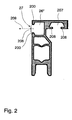
- the insulator profile 1 is produced as an extruded component, as described, for example, in US Pat Fig. 2 is shown.
- insulator profile is formed substantially L-like and has a vertically oriented here second leg 204 and a horizontally oriented here first leg 203.
- connection region 2 in the lower region of the second leg 204.
- the connection area is used holding the insulator profile, for example, positive or non-positive, to connect to the mounting channel of a facade or module profile.
- the connecting region 2 has a U-shaped foot 20, wherein the opening of the U is oriented downwards.
- the U is formed by two clamping legs 22, 22 ', which are interconnected by a web 21.
- a recess 201 is provided in the web 21, which is formed like a channel. It serves as a guide for screwed through the insulator profile 1 screws.
- the thus formed foot 20 is attached, for example, to a fastening channel 40 such that the clamping legs 22, 22 'engage over the fastening channel 40 on the outside.
- a substantially square cross-section insulation chamber 26 connects. It is bounded at the bottom by the web 21 and at the top by an intermediate wall 25. Sideways side walls 24, 24 'are provided. The side walls 24, 24 'go over into the clamping legs 22, 22'. Above this first isolation chamber 26 there is a second isolation chamber 26 ', which in turn is bounded by two partitions 25 and by the sidewall 24 and 24 "The right side wall 24 is angled such that the second leg 204 is in the middle or upper The result is a cross-sectionally trapezoidal insulation chamber 26 '.
- this partition wall has a groove-like recess 201, which serves as the lower recess to a better guide for satisfacfanende screws.
- this second isolation chamber 26 there again follows an isolation chamber 26 ", which is bounded at the top by the head wall 202 and at the bottom by the partition wall 25.
- the isolation chamber is defined by a groove-like opening 206 (better in FIG Fig. 2 to see) so opened that a groove-like recess 27 results.
- the opening 206 allows a recess 28 (see FIG. Fig. 1 ) can be inserted.
- the seal 28 of course closes the opening 206 again and there is a circulation-free and well-insulating isolation chamber 26 ".
- the opening 27 is assumed to be an imaginary area between the respective ends of the wall parts 200.
- On this imaginary surface is the normal 209 (dashed in Fig. 2 drawn in) vertically.
- This standard 209 is pointed or obtuse with the clamping legs 22 and 22 ', in particular at right angles.
- the effective direction of the seal 28, based on the leg extension defined.
- the upper insulation chamber 26 "with the opening 206 is already at the upper end of the second leg 204 and thus in the head portion 29 of the Isolatorprofiles 1. Parts of this second isolation chamber 26" but also belong to the first leg 203, which is substantially horizontal or perpendicular to the second Leg 204 is arranged to extend.
- the first leg 203 extends to the right, wherein the thickness of the leg 203 is slightly smaller than the foot width of the foot 20 and also slightly narrower than the width of the second leg in the upper region after the taper by the oblique
- the contact surface 3 is provided, which directly or indirectly with the Fassaden hypoplasin (in Fig. 1 . 2 not shown) interacting.
- the insulator profile 1 acts here as a glass retaining strip.
- the underside of the first leg 203, which faces the downwardly projecting second leg 204, has a receiving arrangement for the attachment of an outer seal 70.
- the receiving arrangement is formed as a receiving groove 207.
- the opening 206 is bounded by strip-like wall parts 200, which, as shown for example in FIG Fig. 1 is shown, engage in corresponding grooves of the seal 28.
- the strip-like wall parts 200 act as Hintergreifrucn for holding the seal 28th
- a similar arrangement is also provided in the receiving groove 27, which is also C-like, as the recess 27. Again, there are ribs 208 which engage in corresponding recesses of the seal 70.
- the facade filling element When installed, the facade filling element, not shown, is located on the side at which the first leg 203 protrudes laterally beyond the foot 20. It is the task of the contact surface 3 to hold the facade filling element or the insulating glass pane arranged underneath.
- the advantage of the embodiment according to the invention is that the insulator profile shown here can be inserted both with the first leg 203 protruding to the right or projecting to the left. The profile may then only be installed in reverse.
- the head wall 202 is thinner, as the underlying first partition 25.
- the slightly smaller wall thickness does not impair the good insulating effect of the Isolatorprofiles 1, but offers the advantage that mounting screws sunk through the top wall 202 therethrough can be, for example, on a head resting on the top surface 210 pressure bar to allow a rich concern. Since the insulator profile is preferably produced in an extrusion process, the variation of the wall thicknesses is not a technical problem.
- the cross section of the various isolation chambers 26 is chosen to be relatively small. In addition to the here horizontally extending partition walls 25, of course, perpendicular partition walls are conceivable to achieve a further subdivision. It has proven to be beneficial to limit the cross-sectional area of the isolation chambers to about 1 cm 2 , so as to avoid the formation of a negative air circulation, which promotes heat transfer.
- the recesses 27 or receiving groove 207 which are closed by the seals 28 and 70, respectively, also act as isolation chambers in the sense of the invention.
- the fastening channel of the profile there are several possibilities.
- a frictional connection for example, the resilient action of the clamping legs 22, 22 'used.
- a clip connection (which would be a variant of a positive connection) are used, as for example in Fig. 4 is indicated.
- the leg has an inwardly projecting nose-like strip and thus forms part of a clip connection with a groove in the inner seal 71st
- this also constitutes a form-locking connection or mounting of the connecting region of the insulator profile 1 with a profile, in particular the fastening channel or screw channel of a facade or module profile.
- insulator profiles 1 are used. For example, this can be seen very clearly in the two different application examples Fig. 3 and 4 ,
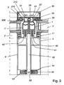
- Fig. 3 . 4 is shown in section the edge region of a facade module according to the invention.
- the façade module consists of frame-like arranged module profiles 4, wherein the facade module at least one Fassaden colllelement 7, 7 ', in particular an insulating glass pane having. Between the Fassaden hypotensus 7 'and the module profile 4, an inner seal 71 is arranged.
- the Fassaden colllelement 7 is held by the insulator profile 1 on the module profile 4 non-positively and / or positively.
- Fig. 3 . 4 is the connection area of a facade according to the invention, consisting of the two adjacently arranged facade modules according to the invention shown.
- the left elements in the reference numerals on a dash otherwise the numbering is the same. It therefore results in a substantially symmetrical structure, but with some interesting differences, in particular with regard to the seal 28, which is used only in the recess 27 of the right Isolatorprofiles 1.
- the crescent-shaped sealing surface 212 of the seal 28 bulges outwardly, so that it closes the opening 206 'of the left insulator profile 1' nevertheless tight and insulating.
- the existing due to the assembly gap or gap 42, 43 between the two insulator profiles 1, 1 ' is reliably sealed by this arrangement.
- a plurality of recesses 27 are provided one above the other on the insulator profile and optionally one or both lying at a height recesses 27, 27 'of the insulator profiles 1, 1' each carry a seal 28 and so give a labyrinth sealing system.
- the gap 43 in the region of the two insulator profiles 1 is thereby securely and reliably closed.
- the invention also provides that cleverly a common pressure bar 5 is installed.
- the pressure bar 5 is thereby screwed alternately into one or preferably both fastening channels 40 or screw channels 40.
- fastening channel 40 which also holds, for example non-positively and positively, with the connection region 2 of the insulator profiles 1, 1 'cooperates.
- the U-shaped foot 20 of the insulator profiles 1 on the other way oriented U-shaped screw 40 or mounting channel 40 plugged or attached and, for example, by a clip connection with a barb arrangement or due to elastic action of the clamping legs 22, 22 'fixed sufficiently fixed thereto.
- the insulator profiles 1 with further fastening screws 41 in the module profile 4, for example, in the mounting channel 40 be screwed and thus give a secure, stable connection for transport.
- the advantage of the invention lies in particular in the fact that the longitudinal screw channel or fastening channel 40 is thus supplied to a multiple utilization. He holds not only the insulator profile 1, whether embracing by clamping effect or screwed with mounting screws 41, but takes in a known manner, the mounting screws whose screw heads 51 press the pressure bar 5 against the profile.
- the integral pressure strip 5 completely covers the gap 43 between the two insulator profiles 1, 1 'and acts as an additional sealing plane, in particular if it is equipped on the back, for example with a rubber pad, etc.
- the pressure bar 5 has on its side facing away from the facade filling elements a snap-in or clip connection for easy pressing a cover strip 50th
- Another essential advantage of the invention is in particular that, although this is a façade modules made from different prefabricated façade modules, the appearance of the finished façade according to the invention corresponds exactly to that of a façade constructed in conventional post and transom construction.
- the invention therefore combines the concept of the post and transom façade, which is very popular in terms of design, with the very favorable production method of a modular façade. There are no optical or design restrictions necessary.
- the sealing surfaces are not directly exposed to weathering, but are protected by the pressure bar 5 and the cover 50.
- the gap 42 lying between the two profiles 4, 4 ' can be closed on the inside of the facade by a spring 52.
- the spacing of the two profiles 4, 4 ' is also intended to provide corresponding compensation lengths due to thermal expansion.
- grooves 43, 43 ' are incorporated in the profiles 4, 4' in the region facing the inside, into which are inserted essentially U-shaped clamping rubbers 44 which hold the spring 52 by clamping, but longitudinally movably.
- the construction according to the invention of the facade modules is not fixed to a design of the module profiles made of metal, preferably for example extruded aluminum profile.
- the invention can be realized in the same way in any sandwich combinations or even in steel profiles or wood profiles.
- the resulting half-post arrangement also allows for certain tolerances a certain length correction or a mounting dimension.
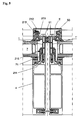
- Fig. 4 shows Fig. 4 in that, in addition to the sealing area 72 between the facade filling element 7 and the profile 4, the inner seal 71 has a sealing part 73 which extends from the edge of the profile 4 inwards over the fastening channel or screw channel 40 and pulls it down on the side of the fastening channel 40 facing the gap 42 is.
- the insulator profile 1 is placed in this embodiment on this seal member 73 and forms an additional sealing plane in conjunction with the inner seal 71. Penetrating water is thus reliably kept away from the mounting channel 40.
- the L-like insulator profile on the outside also carries the outer seal 70 as described. Another difference between the two variants after Fig. 3 and 4 results from the fact that the web 21 in the insulator profile after Fig.
- Fig. 5 is a comparison to the comparable variant Figure 4 yet a slightly different, erfindunssiee variant shown.
- the variant shown here combines the task of isolator profile 1 with the task of pressing bar in an integrally formed component. That causes a separate pressure bar, as in Fig. 3 and 4 is used, here is no longer necessary.
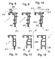
- the insulator profile 1 used here has even more special features. Enlarged, this insulator profile is 1 in Fig. 8 out drawn.
- the foot 20 is in contrast to the one in Fig. 1 shown insulator profile designed differently, namely it is realized as Einsteckfuß 211. It is easy to see that this hose-like Einsteckfuß 211 clampingly engages in the limited by the two walls of the mounting channel 40 gap and is positively and frictionally held. In addition, the insulator profile 1 is held by the fastening screw 51. This results in a space-saving arrangement of the mounting foot.
- a fastening 215, realized here as a fastening groove 215, connects.
- the inner seal 71 which is arranged between the Fassaden Strukturllelement and the profile 4, has a sealing flap 74, the edge strips on the attachment 215 seals. By impressing the edge strip of the sealing flap 74 in the attachment 215, a watertight connection between the inner seal 71 and the insulator profile 1 was produced.
- a receptacle 212 which is realized here as a receiving groove.
- the recording can also be realized as a bar or bridge.
- the receptacle 212 allows a firm connection of the cover strip 50 to the insulator profile.
- a clamping rubber 213 is provided in the receiving groove 212.
- Fig. 6 shows the somewhat similar structure of the insulator profile as Fig. 5
- the insulator profile after Fig. 6 is as Fig. 9 magnified drawn out.
- the difference between the insulator profile after 8 and 9 respectively Fig. 5 and 6 lies in the fact that in the variant Fig. 6 a Einsteckfuß 211 is provided, but no recording or receiving groove 212. This is realized here in the pressure bar 5, 5a.
- the opening of the receiving groove is again parallel to a plane defined by the facade filling surface.
- the receiving grooves 212a and 212b of the left and right pressing bars 5a, 5b are oriented in opposite directions. Both grooves 212a, 212b, take one each Clamping rubber 213a, 213b, on. They work together to keep the cover strip 50 safe and reliable, but easy to assemble and disassemble.
- a sealing strip 14 is provided between the pressure bar 5 and the insulator profile 1.
- Fig. 7 is an insulator profile 1 in use, as shown in Fig. 10 is shown. It essentially corresponds to the insulator profile after Fig. 9 (ie with Einsteckfuß 211 and attachment 215 for the inner seal 71).
- Fig. 11 shows an insulator profile 1, which similar to the solution according to Fig. 12 respectively Fig. 1 , without a fixing 215 is equipped.
- FIGS. 13 and 12 lies in that Fig. 12 on the second leg 204 in the upper region (at the bend) the AufEnglishung 27, the at Fig. 13 does not exist.
- Fig. 6 forms in an alternative of the invention between the two abutting pressure strips 5a, 5b, a gap which is covered only by the cover strip 50.
- the clamping rubber 213a, 213b also serves to seal.
- module seals are further provided between the module profiles, which are fastened to the module profiles (for example, by a separate component) or glued on, for example. It is not only important that the seals are kept for sealing of the insulator profile, even such solutions are part of the invention.
Description
Die Erfindung betrifft eine Fassade, ein Fassadenmodul dieser Fassade sowie ein Isolatorprofil, welches insbesondere in vorgenannten Fassaden Verwendung findet.The invention relates to a facade, a facade module of this facade and an insulator profile, which is used in particular in the aforementioned facades.
Für das Herstellen von Fassaden sind im Stand der Technik im Wesentlichen zwei verschiedene Prinzipien bekannt. Bei der sogenannten Pfosten-Riegel-Fassade werden senkrecht verlaufende Pfosten mit waagrecht verlaufenden Riegeln verbunden und die so gebildeten Fassadenfelder mit Fassadenfüllelementen, zum Beispiel Glasscheiben und dergleichen, ausgefüllt. Diese Vorgehensweise ist im Stand der Technik wohl bekannt. Diese Vorgehensweise setzt dabei voraus, dass eine Glasscheibe erst dann an der Fassade eingesetzt werden kann, wenn die aus Pfosten und Riegeln gebildete Grundstruktur besteht. Dies führt dazu, dass der eigentliche Aufbau der Fassade an der Baustelle aus einer Vielzahl einzelner Bauteile erfolgt, was naturgemäß verhältnismäßig aufwendig und auch gefährlich ist. Dies führt auch zu einem erheblichen Aufwand, da das Gebäude von der Außenseite her voll eingerüstet sein muss, da die Fensterscheiben mit ihrem erheblichen Gewicht von außen zu montieren sind.For the manufacture of facades, essentially two different principles are known in the prior art. In the so-called mullion-transom façade, vertically extending posts are connected with horizontally extending ties and the facade areas thus formed are filled with facade filling elements, for example glass panes and the like. This procedure is well known in the art. This procedure assumes that a glass pane can only be used on the façade if the basic structure formed from posts and bars exists. As a result, the actual construction of the facade at the construction site is made of a plurality of individual components, which is naturally relatively expensive and also dangerous. This also leads to a considerable effort, since the building must be fully scaffolded from the outside, since the windows are to mount with their considerable weight from the outside.
Im Stand der Technik sind des Weiteren sogenannte Elementfassaden bekannt, wobei die Fassade aus einzeln vorgefertigten Fassadenmodulen besteht. Diese Fassadenmodule sind dabei bereits vollständig verglast. Da diese Arbeiten werkstattseitig vorbereitet werden können, sind die Gestehungskosten solcher Fassaden naturgemäß deutlich geringer. Auch der Aufwand, solche Elemente an der Baustelle zu montieren, ist geringer, da diese mit entsprechenden Kranen in das Bauwerk hinein gehoben werden können. Zwischen den einzelnen Modulen verbleibt ein konstruktions- und montagebedingter Spalt, der hernach zu verschließen ist. Die hier bekannten Lösungen befriedigen nicht. Zum einen resultiert daraus eine optische Inhomogenität an der Außen- wie an der Innenseite, da die Felder der Fassadenmodule anders unterteilt sind als der Anschlussbereich zum Nachbarmodul. Zum anderen stellt der Spalt zwischen den einzelnen Fassadenmodulen ein Undichtigkeitsrisiko dar.Furthermore, so-called element facades are known in the prior art, the façade consisting of individually prefabricated facade modules. These façade modules are already completely glazed. Since these works can be prepared workshop side, the cost price of such facades are naturally much lower. Also, the effort to mount such elements on the site, is less, since they can be lifted into the building with appropriate cranes. Between the individual modules remains a constructional and assembly-related gap, which is afterwards to close. The solutions known here do not satisfy. On the one hand, this results in an optical inhomogeneity on the outside as well as on the inside, since the fields of the facade modules are subdivided differently than the connection area to the neighboring module. On the other hand, the gap between the individual facade modules constitutes a risk of leakage.
Aus der Druckschrift
Die vorliegende Erfindung hat es sich zur Aufgabe gemacht, den Stand der Technik zu verbessern und den Montageaufwand vor Ort zu reduzieren.The present invention has set itself the task of improving the state of the art and reducing the installation effort on site.
Hierzu schlägt die Erfindung ein Isolatorprofil vor, welches einen Verbindungsbereich aufweist, um haltend mit einem Profil, insbesondere dem Befestigungskanal eines Fassaden- oder Modulprofils, zusammenzuwirken, wobei das Isolatorprofil eine Anlagefläche aufweist, welche zur mittelbaren oder unmittelbaren Anlage eines Fassadenfüllelementes, insbesondere einer Isolierglasscheibe, dient, im Schnitt im Wesentlichen L-winklig ausgebildet ist und ein erster Schenkel die Anlagenfläche und ein zweiter Schenkel den Verbindungsbereich aufweist.For this purpose, the invention proposes an insulator profile which has a connection area in order to cooperate with a profile, in particular the fastening channel of a facade or module profile, wherein the insulator profile has a contact surface, which for direct or indirect installation of a Fassadenfüllelementes, in particular an insulating glass pane, serves, is formed in the section substantially L-angled and a first leg of the plant surface and a second leg has the connection area.
Der zweite Schenkel, der den Verbindungsbereich belegt, erstreckt sich bevorzugt rechtwinklig zur Ebene, die durch das Fassadenfüllelement gebildet ist. Der erste Schenkel ist hiergegen im Wesentlichen parallel zu dieser durch die Fassadenfüllelemente definierten Ebene.The second leg occupying the connection area preferably extends at right angles to the plane formed by the facade filling element. The first leg is against this substantially parallel to this plane defined by the Fassadenfüllelemente.
Bei den bekannten Lösungen wird letztendlich ein herkömmlicher Aufbau des Fassadenmoduls realisiert. Das heißt, die Glasscheibe beziehungsweise das Fassadenfüllelement wird in herkömmlicher Weise von einer auf der Außenseite angeordneten Pressleiste gehalten. Nach der Erfindung wird jetzt ein Isolatorprofil vorgesehen, welches diese Aufgabe zumindest für den Transport des Fassadenmoduls von der Werkstatt zur Baustelle übernimmt. Im eingebauten Zustand dient das erfindungsgemäße Isolatorprofil dann dazu, die Isolationswirkung gerade im Randbereich der Fassadenfüllelemente beziehungsweise Glasscheiben erheblich zu verbessern.In the known solutions ultimately a conventional structure of the facade module is realized. That is, the glass sheet or the Fassadenfüllelement is held in a conventional manner by a pressure bar arranged on the outside. According to the invention, an insulator profile is now provided which performs this task at least for the transport of the facade module from the workshop to the site. When installed, the insulator profile according to the invention then serves to considerably improve the insulating effect, especially in the edge region of the facade filling elements or glass panes.
Unter einer mittelbaren Anlage eines Fassadenfüllelementes an der Anlagefläche des Isolatorprofiles ist dabei eine Anordnung zu verstehen, bei der zwischen der Anlagefläche und dem Fassadenfüllelement eine Dichtung, zum Beispiel eine Außendichtung, vorgesehen ist. Auf den Einsatz einer entsprechenden Dichtung kann in einer erfindungsgemäßen. Variante auch verzichtet werden, was dann zu einer unmittelbaren Anlage des Fassadenfüllelementes an der Anlagefläche des Isolatorprofiles führt.An indirect installation of a facade filling element on the abutment surface of the insulator profile is understood to mean an arrangement in which a seal, for example an outer seal, is provided between the abutment surface and the facade filling element. On the use of a corresponding seal can in an inventive. Variant also be waived, which then leads to an immediate investment of Fassadenfüllelementes on the contact surface of the insulator profile.
In einer bevorzugten Ausgestaltung der Erfindung ist vorgesehen, dass der Verbindungsbereich einen Fuß aufweist, der insbesondere U-förmig ausgestaltet ist oder als Einsteckfuß realisiert ist. Mit Hilfe des so ausgestatteten Verbindungsbereiches wird eine mechanisch belastbare und stabile Verbindung mit dem Modulprofil, insbesondere dessen Befestigungskanal hergestellt.In a preferred embodiment of the invention it is provided that the connection region has a foot, which is designed in particular U-shaped or realized as Einsteckfuß. With the help of the so-equipped connection area a mechanically strong and stable connection with the module profile, in particular its attachment channel is made.
Für die Ausgestaltung des Fußes gibt es mehrere Varianten. In einer ersten Variante ist der Fuß U-förmig ausgebildet und wird auf einen entsprechend ausgestalteten Sockel oder leistenartigen Befestigungskanal derart aufgestellt, dass die Schenkel des Fußes auf dem Kanal außen aufliegen.There are several variants for the design of the foot. In a first variant of the foot is U-shaped and is placed on a suitably designed base or strip-like mounting channel such that the legs of the foot rest on the outside channel.
In einer anderen Variante ist vorgesehen, dass der Fuß als Einsteckfuß realisiert ist und schlauch- bzw. rohrartig gebildet ist und eine gewisse Elastizität besitzt. Dies erlaubt, dass der Einsteckfuß klemmend zwischen zwei Schenkeln des längsverlaufenden Befestigungskanales eingedrückt werden kann und auch so einen sicheren Halt findet. Natürlich ist es möglich, dass zusätzlich Befestigungsschrauben zur Befestigung des Isolatorprofiles vorgesehen sind.In another variant, it is provided that the foot is realized as Einsteckfuß and tubular or tube-like and has a certain elasticity. This allows the Einsteckfuß clamped between two legs of the longitudinal mounting channel can be pressed and also finds such a secure fit. Of course, it is possible that additional fastening screws are provided for fastening the insulator profile.
Um die Verbesserung der Verbindung zwischen dem Fuß und dem Befestigungskanal beziehungsweise dem Modulprofil zu erhöhen, weist zumindest ein Klemmschenkel auf der Innenseite des Fußes eine nasenartige Leiste auf, die wie eine Clipsverbindung wirkt und in die entsprechenden Gegenteile des Modulprofiles oder Befestigungskanales einschnappend eingreift.In order to increase the improvement of the connection between the foot and the mounting channel or the module profile, at least one clamping leg on the inside of the foot on a nose-like bar, which acts like a clip connection and engages snapping into the corresponding opposite parts of the module profile or mounting channel.
In einer bevorzugten Ausgestaltung ist vorgesehen, dass die Isolationskammer eine Öffnung besitzt und so eine nutartige Ausnehmung bildet. In diese Ausnehmung ist eine Dichtung einsetzbar. Die Anordnung dieser Öffnung ist bevorzugt an dem dem Fassaden- bzw. Modulprofil abgewandten Ende des Isolationsprofiles.In a preferred embodiment it is provided that the isolation chamber has an opening and thus forms a groove-like recess. In this recess, a seal can be used. The arrangement of this opening is preferably on the façade or module profile facing away from the end of the insulation profile.
Die Öffnung kann als Fläche verstanden werden, die eine Flächennormale besitzt. Geschickterweise schließt diese einen Winkel, insbesondere einen rechten Winkel, mit der Längserstreckung des Klemmschenkels ein, alternativ kann dies aber auch rechtwinklig zur Einbaurichtung des Isolatorprofiles auf das Modulprofil oder im Wesentlichen parallel zu einer zur Ebene des Fassadenfüllelementes parallelen Ebene angesehen werden.The opening can be understood as a surface having a surface normal. Cleverly, this includes an angle, in particular a right angle, with the longitudinal extent of the clamping leg, but this can alternatively also be considered perpendicular to the installation direction of the insulator profile on the module profile or substantially parallel to a plane parallel to the facade filling element level.
Wie auch noch später im Zusammenhang mit dem Fassadenmodul beziehungsweise der gesamten Fassade beschrieben werden wird, besitzt das erfindungsgemäße Isolatorprofil eine Vielzahl von Funktionen. Insbesondere wird es in einer Variante auch gleichzeitig als Pressleiste, insbesondere in der fertig montierten Fassade eingesetzt. Auf eine separate zusätzlich anzubringende Pressleiste kann nach diesem Vorschlag verzichtet werden. Dies spart entsprechend Material ein. Aus diesem kombinierten Bauteil das einstückig zwei Funktionen realisiert (als Isolatorprofil und als Pressleiste), kann dann mit den bekannten Mitteln eine Abdeckleiste angeordnet werden, die dann auch den sich zwischen den Fassadenmodulen ergebenden Spalt optisch aber auch technisch (wasserdicht) verdeckt.As will also be described later in connection with the façade module or the entire façade, the insulator profile according to the invention has a multiplicity of functions. In particular, in one variant it is also used simultaneously as a pressure bar, in particular in the completely assembled facade. On a separate addition to be attached pressure bar can be omitted after this proposal. This saves material accordingly. For this combined component which integrally realizes two functions (as insulator profile and as a pressure bar), then a cover strip can be arranged with the known means, which then also covers the gap resulting between the facade modules visually but also technically (waterproof).
In einer bevorzugten Ausgestaltung ist vorgesehen, dass der erste Schenkel auf seiner dem Fuß abgewandten Seite an seinem Schenkelende eine Aufnahmenut besitzt. Die Öffnung dieser Aufnahmenut ist dabei zum Beispiel parallel zur Ebene des Fassadenfüllelementes oder winklig beziehungsweise rechtwinklig hierzu. Diese Aufnahmenut ist zum Beispiel an dem den Knick des L-artigen Isolatorprofiles abgelegenen Bereich vorgesehen. Äquivalent zu dieser Ausgestaltung ist eine Anordnung, bei welcher ein längs verlaufender Steg oder Leiste, insbesondere für Befestigungs- und/oder Abdichtzwecke an dem ersten Schenkel in gleicher Weise angeordnet ist. An dieser Stelle sei auf das Bezugszeichen 212 in
Mit Hilfe der Aufnahmenut wird in einer Variante eine Abdeckleiste befestigt. Die Abdeckleiste bedeckt dabei den sich zwischen den Fassadenmodulen ergebenden Spalt, vorteilhafter Weise wird in die Aufnahmenut ein Klemmgummi eingelegt, der zum einen eine ausreichende sichere Befestigung der Abdeckleiste ergibt und auf der anderen Seite durch seine Elastizität auch entsprechende Maßtoleranzen ausgleichen hilft.With the help of the receiving groove in a variant, a cover strip is attached. The cover strip covers the resulting between the facade modules gap, advantageously, a clamping rubber is inserted into the receiving groove, which on the one hand provides a sufficient secure attachment of the cover and on the other hand by its elasticity also compensates for corresponding dimensional tolerances.
In einer weiteren Ausgestaltung ist vorgesehen, dass der erste Schenkel auf seiner dem Fuß abgewandten Seite von längs verlaufenden Leisten begrenzt ist. Diese dienen zum Beispiel zur Aufnahme einer Fixierplatte. Die Fixierplatte besteht vorzugsweise aus Metall und ist bündig im oberen Bereich des Isolatorprofiles angeordnet und eingelassen. Diese Fixierplatte besteht vorzugsweise aus Kurzstücken und dient zur stabilen Vorfixierung der Glasscheibe beim Transport und sind so ausgebildet, dass sie nicht entfernt werden müssen. Neben ihrer Funktion als Fixierung, also Aussteifung, bieten die Fixierplatten, die in durchaus größerer Anzahl auf dem Isolatorprofil angeordnet sind, auch einen Befestigungsgrund für die Pressleiste.In a further embodiment, it is provided that the first leg is bounded on its side facing away from the foot by longitudinally extending strips. These serve for example for receiving a fixing plate. The fixing plate is preferably made of metal and is arranged flush with and embedded in the upper region of the insulator profile. This fixing plate is preferably made of short pieces and is used for stable prefixing of the glass during transport and are designed so that they do not need to be removed. In addition to their function as a fixation, so stiffening, provide the fixing plates, which are arranged in quite a larger number on the insulator profile, also a mounting base for the pressure bar.
In einer bevorzugten Ausgestaltung ist vorgesehen, dass das Isolatorprofil, insbesondere der zweite Schenkel, der winklig, insbesondere rechtwinklig zur Fassadenfüllflächenebene orientiert ist, eine Befestigung trägt, die für die Anordnung einer Innendichtung dient. Diese Befestigung ist zum Beispiel als Befestigungsnut oder als Befestigungssteg realisierbar. Die Innendichtung befindet sich zwischen dem innenseitig angeordneten Fassaden- oder Modulprofil und dem Fassadenfüllelement. Es wird dadurch eine sichere Abdichtung zwischen dem Falzraum und dem Modulprofil erreicht. Insbesondere ist diese Anordnung montagefreundlich, da die einzelnen Elemente nach und nach miteinander verbaut werden können. Geschickterweise wird das Isolatorprofil hernach im Modulprofil beziehungsweise dessen Befestigungskanal verschraubt und wirkt auch gleichzeitig als Pressleiste, wodurch ein fertig transportierbares Element entsteht.In a preferred embodiment, it is provided that the insulator profile, in particular the second leg, which is oriented at an angle, in particular at right angles to the façade filling plane, carries a fastening which serves for the arrangement of an inner seal. This attachment can be realized, for example, as a fastening groove or as a fastening web. The inner seal is located between the façade or module profile arranged on the inside and the facade filling element. It is achieved by a secure seal between the rebate and the module profile. In particular, this arrangement is easy to install, since the individual elements can be gradually installed with each other. Cleverly, the isolator profile is subsequently screwed into the module profile or its fastening channel and at the same time acts as a pressure bar, whereby a ready transportable element is created.
Des weiteren wird die erfindungsgemäße Aufgabe durch ein Fassadenmodul gelöst, welches aus rahmenartig angeordneten Modulprofilen besteht, wobei das Fassadenmodul mindestens ein Fassadenfüllelement, insbesondere eine Isolierglasscheibe, aufweist, wobei zwischen Fassadenfüllelement und den Modulprofilen eine Innendichtung angeordnet ist und das Fassadenfüllelement durch ein Isolatorprofil, bevorzugt wie beschrieben, an dem Modulprofil kraft- und/oder formschlüssig gehalten ist. Durch den erfindungsgemäßen Einsatz des Isolatorprofiles bei dem ebenfalls zur Erfindung gehörenden Fassadenmodul wird erreicht, dass ein fertig verbaubares und auch transportierbares Fassadenmodul zur Verfügung steht, wobei das über die gesamte Kantenlänge des Fassadenfüllelementes angeordnete Isolatorprofil nicht nur eine Halteaufgabe erfüllt, sondern auch gleichzeitig einen Transportschutz des Fassadenfüllelementes beziehungsweise der Glasscheibe gerade an den empfindlichen Randkanten ergibt.Furthermore, the object of the invention is achieved by a facade module, which consists of frame-like module profiles, the facade module at least one Fassadenfüllelement, in particular an insulating glass, having between Fassadenfüllelement and the module profiles an inner seal is disposed and the Fassadenfüllelement by an insulator profile, preferably like described, is held positively and / or positively on the module profile. Through the use according to the invention of the insulator profile in the façade module also belonging to the invention it is achieved that a ready-to-install and also transportable façade module is available, the insulator profile arranged over the entire edge length of the façade filling element not only fulfilling a holding task, but at the same time also providing transport protection Façade filling element or the glass pane just at the sensitive edges.
Soweit nachfolgend oftmals nur von einer Isolierglasscheibe oder Glasscheibe gesprochen wird, so beschränkt dies die Erfindung nicht auf diesen speziellen Anwendungsfall. Es sind gleichwohl immer alle möglichen Fassadenfüllelemente, gleich welcher Ausgestaltung und Material, hiervon ebenfalls mit umfasst und erfindungsgemäß beschrieben.As far as subsequently is often spoken only of an insulating glass or glass, so this does not limit the invention to this particular application. However, there are always all possible Fassadenfüllelemente, regardless of what design and material, thereof also includes and described according to the invention.
Geschickterweise wird vorgesehen, dass das Isolatorprofil an dem Modulprofil kraft- und/oder formschlüssig gehalten ist. Hierzu stehen eine Vielzahl unterschiedlicher Varianten zur Verfügung. Dies kann zum Beispiel durch ein Clipsen, Klemmen, durch Befestigungsschrauben, Klebung usw. erfolgen.Cleverly it is provided that the insulator profile is held non-positively and / or positively on the module profile. There are a large number of different variants available for this purpose. This can be done, for example, by clipping, clamping, by fastening screws, gluing, etc.
In einer vorteilhaften Ausgestaltung der Erfindung wird vorgeschlagen, dass das Isolatorprofil als Pressleiste wirkt und durch Befestigungsschrauben formschlüssig am Modulprofil gehalten ist und insbesondere während des Transportes das Fassadenfüllelement sichert. Der Aufbau des erfindungsgemäßen Fassadenmoduls wird durch diesen Vorschlag erheblich vereinfacht, da die separate Anordnung einer Pressleiste nicht notwendig ist. Das Isolatorprofil übernimmt überraschenderweise diese zusätzliche Aufgabe und kann diese auch problemlos mechanisch erfüllen. Es resultiert ein gut transportierbarer, weitestgehend fertig vormontierter Gegenstand, der werksseitig vorbereitet ist und als fertiges Bauteil in das Bauwerk nur noch einzubauen ist.In an advantageous embodiment of the invention it is proposed that the insulator profile acts as a pressure bar and is held by fastening screws positively on the module profile and in particular secures the Fassadenfüllelement during transport. The structure of the facade module according to the invention is considerably simplified by this proposal, since the separate arrangement of a pressure bar is not necessary. The insulator profile surprisingly takes over this additional task and can also meet this problem mechanically. The result is a well transportable, largely finished pre-assembled object that is factory-prepared and as a finished component in the building only to install.
Alternativ hierzu ist vorgesehen, dass eine von dem Isolatorprofil getrennte Pressleiste vorgesehen ist, die mit Befestigungsschrauben formschlüssig am Modulprofil gehalten ist und insbesondere während des Transportes das Fassadenfüllelement sichert. Die Anordnung bei dieser Variante ist so gewählt, dass die Befestigungs- und Isolationsaufgabe wiederum auf zwei Bauteile verteilt ist. Allerdings besitzt jedes Fassadenmodul selber eine vollständig wirksame Pressleiste. Die Erfindung ist insofern sehr variabel, da die Aufgabe der Pressleiste entweder in einer ersten Variante von dem Isolatorprofil übernommen wird. In einer zweiten Variante wird eine Pressleiste eingesetzt, die über dem Isolatorprofil auf dieses aufgeschraubt wird und die Pressleiste über das Isolatorprofil mit dessen Anlagefläche das Fassadenfüllelement hält.Alternatively, it is provided that a separate from the insulator profile pressure bar is provided, which is held with fastening screws form fit on the module profile and in particular secures the Fassadenfüllelement during transport. The arrangement in this variant is chosen so that the fastening and isolation task is in turn distributed over two components. However, each façade module itself has a completely effective pressure bar. The invention is very variable in that the task of the pressure bar is taken over in a first variant of the insulator profile either. In a second variant, a pressure bar is used, which is screwed onto the insulator profile on this and holds the pressure bar on the insulator profile with its contact surface the Fassadenfüllelement.
Bei diesen beiden vorgenannten Fällen besitzt jedes Fassadenmodul eine eigene Pressleiste, entweder tatsächlich gegenständlich oder funktional gekoppelt mit dem Isolatorprofil.In these two aforementioned cases, each facade module has its own pressure bar, either actually objectively or functionally coupled with the insulator profile.
In der dritten Variante (diese wird insbesondere bei der erfindungsgemäßen Fassade nochmals erläutert) wird eine gemeinsame Pressleiste vorgesehen, die die beiden aneinander anstehenden und zusammen dicht wirkenden Isolatorprofile zweier benachbart angeordneter Fassadenmodule abdeckt und sichert.In the third variant (this is explained again in particular in the façade according to the invention), a common pressure strip is provided, which covers and secures the two adjoining and tightly acting insulator profiles of two adjacently arranged facade modules.
Insbesondere bei der Variante, wo jedem Fassadenmodul eine eigenständige Pressleiste zugeordnet ist, aber auch bei der Variante, bei der eine Pressleiste für beide Isolatorprofile eingesetzt ist, wird vorgeschlagen, dass die Pressleiste eine Aufnahmenut aufweist, in welcher ein Klemmgummi einlegbar ist. Die Aufnahmenut ist geschickterweise jeweils so orientiert, dass sie auf die Fassadenfüllelemente gerichtet ist. Bei den zusammengesetzten Fassadenmodulen der Fassade sind daher die Aufnahmenuten benachbarter Pressleisten entgegengerichtet orientiert, ein Klemmgummi, der dort eingesetzt ist, eignet sich zur Befestigung der Abdeckleiste und erlaubt problemlos auch entsprechende Toleranzausgleiche in Querrichtung.In particular, in the variant where each facade module is assigned an independent pressure bar, but also in the variant in which a pressure bar is used for both insulator profiles, it is proposed that the pressure bar has a receiving groove in which a clamping rubber can be inserted. The receiving groove is cleverly oriented in each case so that it is directed to the Fassadenfüllelemente. In the composite façade modules of the facade, therefore, the receiving grooves adjacent pressure bars are oriented in opposite directions, a clamping rubber, which is used there, is suitable for fastening the cover and easily permits appropriate tolerance compensation in the transverse direction.
In einer weiteren vorteilhaften Ausgestaltung der Erfindung ist vorgesehen, dass zwischen Isolatorprofil und Pressleiste ein Dichtprofil oder Dichtband vorgesehen ist. Dieses Dichtband oder Dichtprofil erhöht die Dichtigkeit und wird insbesondere bei Anordnungen im Dachbereich eingesetzt, um eine hohe Dichtigkeit zu erreichen.In a further advantageous embodiment of the invention, it is provided that a sealing profile or sealing strip is provided between insulator profile and pressure bar. This sealing tape or sealing profile increases the tightness and is used in particular in arrangements in the roof area to achieve a high density.
Des weiteren wird die eingangs beschriebene Aufgabe durch eine Fassade gelöst, welche aus mindestens zwei benachbart zueinander angeordneten Fassadenmodulen, bevorzugt wie beschrieben, besteht, wobei eine Pressleiste über dem Spalt zwischen den Fassadenmodulen angeordnet ist. Durch die Erfindung ist es möglich, eine elementierte Riegel-Pfosten-Fassade oder elementierte Pfosten-Riegel-Fassade zu realisieren. Der Vorteil der Erfindung liegt insbesondere darin, dass das Gestaltungsbild einer Pfosten-Riegel-Fassade (gleichwertig hierzu eine Riegel-Pfosten-Fassade) mit Hilfe des erfindungsgemäßen Vorschlages erreicht wird, allerdings ist der Aufwand für die Herstellung einer solchen elementierten Fassade erheblich geringer wie bei dem der Stand der Technik bekannten Elementfassaden.Furthermore, the object described above is achieved by a facade, which consists of at least two adjacently arranged facade modules, preferably as described, wherein a pressure bar is arranged above the gap between the facade modules. By the invention it is possible to realize an elementary transom-post facade or elemental post and beam facade. The advantage of the invention lies in the fact that the design image of a mullion-transom façade (equivalent to a transom post façade) is achieved with the help of the proposal according to the invention, however, the cost of producing such an elementary facade is considerably lower than at the prior art element facades known.
Die Pressleiste ist daher gemeinsam für zwei benachbarte Fassadenmodule vorgesehen und führt zu dem Vorteil, dass sich das äußere Erscheinungsbild der erfindungsgemäßen Fassade obwohl sie aus einzelnen vorgefertigten Fassadenmodulen besteht, von dem Erscheinungsbild einer zum Beispiel als Pfosten-Riegel-Fassade ausgebildeten Konstruktion nicht unterscheidet. Dies eröffnet im Übrigen die Möglichkeit, das durch den Rahmen der Modulprofile definierte Fassadenmodul mit entsprechenden Pfosten-Riegel-Profilen in gewohnter Weise auszustreben und zu unterteilen und so auf bewährte Bauteile und Vorgehensweisen zurückzugreifen.The pressure bar is therefore provided jointly for two adjacent facade modules and leads to the advantage that the appearance of the façade according to the invention, although it consists of individual prefabricated facade modules, of the appearance a construction designed for example as a mullion-transom façade does not differ. This, moreover, opens up the possibility of outstripping and subdividing the façade module defined by the frame of the module profiles with the corresponding post and beam profiles in the usual way and thus of resorting to proven components and procedures.
Neben diesem gestalterischen Vorteil erreicht die Erfindung aber auch eine Verbesserung der Dichtigkeit der erfindungsgemäßen Fassade, wobei die außen liegende Pressleiste auch den zwischen den Fassadenmodulen konstruktionsbedingt vorhandenen Spalt sicher und zuverlässig abdeckt und somit auch abdichtet. Da die Pressleiste in der Regel aus Kunststoff, Hartkunststoff oder auch Metall gefertigt ist, ist diese auch ausreichend schlagregendicht.In addition to this design advantage, however, the invention also achieves an improvement in the impermeability of the façade according to the invention, wherein the outer pressure strip also reliably and reliably covers the gap present between the façade modules by design and thus also seals them. Since the pressure bar is usually made of plastic, hard plastic or metal, this is also sufficient impact rain.
Zwar muss die Montage der Pressleiste abschließend nach wie vor von außen ausgeführt werden, wenn die Fassadenmodule jeweils montiert sind, sie können jedoch aufgrund der Einfachheit der Arbeiten (es müssen keine schweren Glasscheiben von außen in die Fassade eingesetzt werden) über einen Arbeitskorb, zum Beispiel einen Hubsteiger, ausgeführt werden.Finally, the installation of the pressure bar must finally be carried out from the outside, if the facade modules are mounted in each case, but because of the simplicity of the work (no heavy glass panes have to be inserted from the outside into the facade) via a work basket, for example a hoist, be executed.
Das erfindungsgemäß vorgeschlagene Isolatorprofil ergibt zunächst eine erhebliche Verbesserung der Wärmedämmung im Spaltbereich der erfindungsgemäßen Fassaden. Es dient zu einer Vorfixierung der Isolierglasscheiben, insbesondere für den Transport. Es nimmt geschickterweise die äußere Glasdichtung, die Außendichtung, auf. Da die ganzen Montagearbeiten in der Werkstatt vorgenommen werden, sind Montagefehler deutlich geringer und auch die Herstellung der Elemente ist absolut wetterunabhängig. Bekanntermaßen erfolgt eine werkstattseitige Herstellung immer günstiger als eine baustellenseitige Erstellung des Bauteiles.The insulator profile proposed according to the invention initially results in a considerable improvement of the thermal insulation in the gap region of the facades according to the invention. It serves to pre-fix the insulating glass panes, especially for transport. It cleverly picks up the outer glass seal, the outer seal. Since the entire assembly work is carried out in the workshop, assembly errors are significantly lower and the production of the elements is absolutely weather-independent. As is known, a workshop-side production is always cheaper than a site-side creation of the component.
In einer bevorzugten Ausgestaltung der erfindungsgemäßen Fassade wird vorgeschlagen, dass die Abdeckleiste direkt oder durch einen in eine Aufnahmenut eingesteckten Klemmgummi von je einem als Pressleiste wirkenden Isolatorprofil gehalten ist. Die hier beschriebene Variante zeigt sich insbesondere in
Die Erfindung umfasst mehrere Gegenstände, nämlich das Isolatorprofil, die Fassade sowie das Fassadenmodul. Um Wiederholungen zu vermeiden, werden nicht alle Merkmalskombinationen, die denkbar sind, einzeln aufgeführt, sondern teilweise nur bei dem einen oder anderen Gegenstand beschrieben. Dies aber beschränkt die Erfindung und die Anmeldung in keinster Weise nur auf diesen hier im Einzelfall beschriebenen Fall, Merkmale, die im Zusammenhang mit dem Isolatorprofil beschrieben sind, sind natürlich im Zusammenhang mit der Fassade oder dem Fassadenmodul genauso zu kombinieren, wie Merkmale, die beim Fassadenmodul beschrieben sind, auch bei Fassade oder im Isolatorprofil eingesetzt werden können. Natürlich sind auch Merkmale, die nur im Zusammenhang mit der Fassade beschrieben sind, gleichwohl als mit dem Isolatorprofil oder dem Fassadenmodul offenbart anzusehen. All diese Kombinationen sind Gegenstand der Erfindung und der Offenbarung dieser Anmeldung.The invention comprises several objects, namely the insulator profile, the facade and the facade module. In order to avoid repetition, not all feature combinations that are conceivable are listed individually, but partially described only in one or the other subject. However, this does not limit the invention and the application in any way only to this case described here in a particular case, features that are described in connection with the insulator profile are, of course, to be combined in the context of the facade or façade module as well as features that Façade module are described, can also be used on the facade or in the insulator profile. Of course, features that are described only in connection with the facade, nevertheless, to be regarded as disclosed with the insulator profile or the facade module. All of these combinations are the subject of the invention and the disclosure of this application.
Bevorzugte Ausgestaltungen der Erfindung sind in den Unteransprüchen beschrieben.Preferred embodiments of the invention are described in the subclaims.
In der Zeichnung ist die Erfindung schematisch dargestellt. Es zeigen:
- Fig. 1
- in einem Querschnitt das erfindungsgemäße Isolatorprofil mit eingesetzten Dichtungen;
- Fig. 2, 8 bis 13
- je in einem Querschnitt verschiedene Varianten des erfindungsgemäßen Isolatorprofil und
- Fig. 3
bis 7 - jeweils in einem Querschnitt einen Ausschnitt der erfindungsgemäßen Fassade, bestehend aus zwei benachbart angeordneten erfindungsgemäßen Fassadenmodulen unter Verwendung des erfindungsgemäßen Isolatorprofils.
- Fig. 1
- in a cross section the insulator profile according to the invention with inserted seals;
- Fig. 2, 8 to 13
- each in a cross section different variants of the insulator profile according to the invention and
- Fig. 3 to 7
- in each case in a cross section a section of the facade according to the invention, consisting of two adjacently arranged facade modules according to the invention using the insulator profile according to the invention.
In
Das in
In dem hier gezeigten Ausführungsbeispiel weist der Verbindungsbereich 2 einen U-förmigen Fuß 20 auf, wobei die Öffnung des U's nach unten orientiert ist. Das U wird gebildet von zwei Klemmschenkeln 22, 22', die durch einen Steg 21 miteinander verbunden sind. Auf der dem U abgewandten Seite des Steges 21 ist in dem Steg 21 eine Vertiefung 201 vorgesehen, die rinnenartig ausgebildet ist. Sie dient als Führung für durch das Isolatorprofil 1 durchgeschraubte Schrauben. Der so ausgebildete Fuß 20 wird zum Beispiel auf einen Befestigungskanal 40 derart aufgesteckt, dass die Klemmschenkel 22, 22' den Befestigungskanal 40 außen übergreifen.In the embodiment shown here, the connecting
Oberhalb des Fußes 20 schließt sich eine im Wesentlichen im Querschnitt quadratische Isolationskammer 26 an. Sie wird nach unten hin begrenzt durch den Steg 21 und nach oben hin durch eine Zwischenwand 25. Seitlich sind Seitenwände 24, 24' vorgesehen. Die Seitenwände 24, 24' gehen dabei über in die Klemmschenkel 22, 22'. Oberhalb dieser ersten Isolationskammer 26 befindet sich eine zweite Isolationskammer 26', die ihrerseits wiederum von zwei Zwischenwänden 25 sowie von der Seitenwand 24 und 24" begrenzt ist. Die rechte Seitenwand 24 ist abgewinkelt, derart, dass sich der zweite Schenkel 204 im mittleren beziehungsweise oberen Bereich verjüngt. Es resultiert eine im Querschnitt trapezförmige Isolationskammer 26'.Above the
Auch diese Zwischenwand besitzt eine rinnenartige Vertiefung 201, die wie die unten liegende Vertiefung zu einer besseren Führung für einzudrehende Schrauben dient. Oberhalb dieser zweiten Isolationskammer 26' schließt sich wieder eine Isolationskammer 26" an. Diese wird oben durch die Kopfwand 202 und unten durch die Zwischenwand 25 beschränkt. Im linken Bereich ist die Isolationskammer durch eine nutartige Öffnung 206 (besser in
Die Öffnung 27 ist als gedachte Fläche zwischen den jeweiligen Enden der Wandteile 200 anzunehmen. Auf dieser gedachten Fläche steht die Normale 209 (gestrichelt in
Die obere Isolationskammer 26" mit der Öffnung 206 liegt bereits am oberen Ende des zweiten Schenkels 204 und somit im Kopfbereich 29 des Isolatorprofiles 1. Teile dieser zweiten Isolationskammer 26" gehören aber auch zu dem ersten Schenkel 203, der im wesentlichen horizontal beziehungsweise rechtwinklig zum zweiten Schenkel 204 verlaufend angeordnet ist.The
In der hier gezeigten Ausgestaltung erstreckt sich dann der erste Schenkel 203 nach rechts, wobei die Dicke des Schenkels 203 etwas geringer ist als die Fußbreite des Fußes 20 und auch noch etwas schmaler als die Breite des zweiten Schenkels im oberen Bereich nach der Verjüngung durch die schräg angeordnete Seitenwand 24". An diesem ersten Schenkel 203 ist die Anlagefläche 3 vorgesehen, die mittelbar oder unmittelbar mit dem Fassadenfüllelement 7 (in
Die Unterseite des ersten Schenkels 203, die dem nach unten abstehenden zweiten Schenkel 204 zugewandt ist, besitzt eine Aufnahmeanordnung für die Befestigung einer Außendichtung 70. In dem hier gezeigten Ausführungsbeispiel ist die Aufnahmeanordnung als Aufnahmenut 207 ausgebildet.The underside of the
Die Öffnung 206 ist begrenzt von leistenartigen Wandteilen 200, die, wie es zum Beispiel in
Eine ähnliche Anordnung ist auch bei der Aufnahmenut 27 vorgesehen, die ebenso C-artig ausgebildet ist, wie die Ausnehmung 27. Auch hier stehen Rippen 208 vor, die in entsprechende Ausnehmungen der Dichtung 70 eingreifen.A similar arrangement is also provided in the receiving
Im eingebauten Zustand befindet sich das nicht gezeigte Fassadenfüllelement auf der Seite, an der sich der erste Schenkel 203 seitlich über den Fuß 20 auskragt. Es ist Aufgabe der Anlagefläche 3, das darunter angeordnete Fassadenfüllelement beziehungsweise die Isolierglasscheibe festzuhalten. Der Vorteil der Ausgestaltung nach der Erfindung ist, dass das hier gezeigte Isolatorprofil sowohl mit rechts auskragendem oder nach links auskragendem ersten Schenkel 203 einsetzbar ist. Das Profil ist dann gegebenenfalls nur umgekehrt einzubauen.When installed, the facade filling element, not shown, is located on the side at which the
In einer Variante ist vorgesehen, dass die Kopfwand 202 dünner ausgebildet ist, wie die darunter liegende erste Zwischenwand 25. Die etwas geringere Wandstärke beeinträchtigt in keinster Weise die gute Isolationswirkung des Isolatorprofiles 1, bietet aber den Vorteil, dass Befestigungsschrauben durch die Kopfwand 202 hindurch versenkt werden können, um zum Beispiel auf einer auf der Kopffläche 210 aufliegenden Pressleiste ein sattes Anliegen zu erlauben. Da das Isolatorprofil bevorzugt in einem Extrudierverfahren hergestellt ist, ist die Variation der Wandstärken kein technisches Problem.In a variant, it is provided that the
Der Querschnitt der verschiedenen Isolationskammern 26 wird verhältnismäßig gering gewählt. Neben den hier waagrecht verlaufenden Zwischenwänden 25 sind natürlich auch senkrecht verlaufende Zwischenwände denkbar, um eine weitere Unterteilung zu erreichen. Es hat sich dabei als günstig erwiesen, die Querschnittsfläche der Isolationskammern auf ca. 1 cm2 zu begrenzen, um so das Ausbilden einer negativen Luftzirkulation, die den Wärmetransport fördert, zu vermeiden. Auch die durch die Dichtungen 28 beziehungsweise 70 verschlossenen Ausnehmungen 27 beziehungsweise Aufnahmenut 207 wirken als Isolationskammern im Sinne der Erfindung.The cross section of the
Zum Befestigen des Isolatorprofiles 1 auf dem Profil, bevorzugt dem Befestigungskanal des Profils, bestehen mehrere Möglichkeiten. Durch einen Kraftschluss wird zum Beispiel die federnde Wirkung der Klemmschenkel 22, 22' verwendet.For fastening the
Es könnte aber auch eine Clipsverbindung (was eine Variante einer formschlüssigen Verbindung wäre) eingesetzt werden, wie dies zum Beispiel in
Zu der formschlüssigen Verbindung zählt aber auch das Eindrehen einer Befestigungsschraube in das Isolatorprofil 1. Auch dies stellt eine formschlüssige Verbindung beziehungsweise Halterung des Verbindungsbereiches des Isolatorprofiles 1 mit einem Profil, insbesondere dem Befestigungskanal oder Schraubkanal eines Fassaden- oder Modulprofiles dar.However, this also constitutes a form-locking connection or mounting of the connecting region of the
Erfindungsgemäß werden mindestens zwei verschiedene Typen von Isolatorprofilen 1 eingesetzt. Dies sieht man zum Beispiel sehr deutlich in den beiden unterschiedlichen Anwendungsbeispielen nach
In
In
In einer Variante ist dabei vorgesehen, dass mehrere Ausnehmungen 27 übereinander am Isolatorprofil vorgesehen sind und gegebenenfalls eine oder beide auf einer Höhe liegenden Ausnehmungen 27, 27' der Isolatorprofile 1, 1' je eine Dichtung 28 tragen und so ein Labyrinth-Dichtungssystem ergeben. Der Spalt 43 im Bereich der beiden Isolatorprofile 1 wird dadurch sicher und zuverlässig verschlossen.In a variant, it is provided that a plurality of
Zusätzlich aber sieht die Erfindung auch vor, dass geschickterweise eine gemeinsame Pressleiste 5 verbaut wird. Die Pressleiste 5 wird dabei in eine oder bevorzugt in beide Befestigungskanäle 40 beziehungsweise Schraubkanäle 40 alternierend eingeschraubt.In addition, however, the invention also provides that cleverly a
Es handelt sich dabei um den gleichen Befestigungskanal 40, der auch haltend, zum Beispiel kraft- und formschlüssig, mit dem Verbindungsbereich 2 der Isolatorprofile 1, 1' zusammenwirkt. Dabei ist der U-förmige Fuß 20 der Isolatorprofile 1 auf den andersherum orientierten U-förmigen Schraubkanal 40 beziehungsweise Befestigungskanal 40 aufgesteckt oder aufgesetzt und zum Beispiel durch eine Clipsverbindung mit einer Widerhakenanordnung oder aufgrund elastischer Wirkung der Klemmschenkel 22, 22' ausreichend fest hierauf befestigt.These are the
Zum Beispiel können für Transportzwecke die Isolatorprofile 1 mit weiteren Befestigungsschrauben 41 in das Modulprofil 4, zum Beispiel in den Befestigungskanal 40, eingedreht sein und so eine sichere, stabile Verbindung auch für den Transport ergeben. Der Vorteil der Erfindung liegt insbesondere darin, dass der längsverlaufende Schraubkanal beziehungsweise Befestigungskanal 40 so einer vielfachen Ausnutzung zugeführt wird. Er hält nicht nur das Isolatorprofil 1, sei es umgreifend durch Klemmwirkung oder eingeschraubt mit Befestigungsschrauben 41, sondern nimmt in bekannter Weise auch die Befestigungsschrauben auf, deren Schraubenköpfe 51 die Pressleiste 5 gegen das Profil pressen.For example, for transport purposes, the insulator profiles 1 with further fastening screws 41 in the
Da die Pressleiste satt auf der Kopffläche 210 des oben liegenden kürzeren ersten Schenkels 203 aufliegt, erfolgt ein vollflächiges Andrücken des Isolatorprofiles 1 einerseits gegen das Profil 4 und andererseits mittelbar oder unmittelbar durch die Anlagefläche 3 beziehungsweise der daran gegebenenfalls vorgesehenen Außendichtungen 70 an die Fassadenfüllelemente. Es entsteht eine sehr stabile und dichte Befestigung der Fassadenmodule untereinander. Darüber hinaus verdeckt die einstückige Pressleiste 5 vollständig den Spalt 43 zwischen den beiden Isolatorprofilen 1, 1' und wirkt als zusätzliche Dichtebene, insbesondere wenn diese rückseitig zum Beispiel mit einer Gummiauflage usw. ausgestattet ist.Since the pressure strip rests satisfactorily on the
In bekannter Weise besitzt die Pressleiste 5 auf ihrer von den Fassadenfüllelementen abgewandten Seite eine Einschnapp- oder Clipsverbindung zum einfachen Aufdrücken einer Abdeckleiste 50.In a known manner, the
Ein weiterer wesentlicher Vorzug der Erfindung liegt insbesondere darin, dass, obwohl es sich hier um eine aus verschiedenen werkstattseitig vorgefertigten Fassadenmodulen bestehende Fassade handelt, das Erscheinungsbild der fertigen, erfindungsgemäßen Fassade der einer in herkömmlicher Pfosten- und Riegel-Bauweise erstellten Fassade exakt entspricht. Die Erfindung kombiniert daher das gestalterisch sehr beliebte Konzept der Pfosten- und Riegel-Fassade mit der sehr günstigen Herstellungsweise einer Fassade in Modulbauweise. Es sind keine optischen oder gestalterischen Einschränkungen notwendig. Die Dichtungsflächen sind nicht direkt der Bewitterung ausgesetzt, sondern sind von der Pressleiste 5 und der Abdeckleiste 50 geschützt angeordnet.Another essential advantage of the invention is in particular that, although this is a façade modules made from different prefabricated façade modules, the appearance of the finished façade according to the invention corresponds exactly to that of a façade constructed in conventional post and transom construction. The invention therefore combines the concept of the post and transom façade, which is very popular in terms of design, with the very favorable production method of a modular façade. There are no optical or design restrictions necessary. The sealing surfaces are not directly exposed to weathering, but are protected by the
Des Weiteren kann der zwischen den beiden Profilen 4, 4' liegende Spalt 42 auf der Innenseite der Fassade durch eine Feder 52 verschlossen sein. Die Beabstandung der beiden Profile 4, 4' ist auch dafür vorgesehen, entsprechende Kompensationslängen aufgrund thermischer Ausdehnung vorzusehen. Hierzu sind in den Profilen 4, 4' in dem der Innenseite zugewandten Bereich Nuten 43, 43' eingearbeitet, in welche im wesentliche U-förmige Klemmgummis 44 eingesetzt sind, die die Feder 52 klemmend, aber längs beweglich festhalten.Furthermore, the
Der erfindungsgemäße Aufbau der Fassadenmodule ist auf eine Ausbildung der Modulprofile aus Metall, bevorzugt zum Beispiel stranggepresstes Aluminiumprofil, nicht festgelegt. Die Erfindung ist in gleicher Weise in beliebigen Sandwich-Kombinationen oder auch bei Stahlprofilen beziehungsweise Holzprofilen realisierbar. So ist es zum Beispiel möglich, den Befestigungskanal 40 bei einer Holzkonstruktion als separates Bauteil auszuführen, damit dieses auf dem Holzprofil befestigbar ist, um dann dort den bekannten, hier gezeigten Aufbau mit Hilfe des Isolatorprofiles 1 zu realisieren. Die daraus resultierende Halbpfosten-Anordnung erlaubt auch in gewissen Toleranzen eine gewisse Längenkorrektur beziehungsweise ein Montagemaß.The construction according to the invention of the facade modules is not fixed to a design of the module profiles made of metal, preferably for example extruded aluminum profile. The invention can be realized in the same way in any sandwich combinations or even in steel profiles or wood profiles. Thus, it is possible, for example, to carry out the
Der Unterschied zwischen der in
Hingegen zeigt
In
Das hier eingesetzte Isolatorprofil 1 weist noch weitere Besonderheiten auf. Vergrößert ist dieses Isolatorprofil 1 in
Zunächst ist der Fuß 20 im Gegensatz zu dem in
Gleich oberhalb des Befestigungsfußes 20 schließt sich eine Befestigung 215, hier als Befestigungsnut 215 realisiert, an. Die Innendichtung 71, die zwischen dem Fassadenfüllelement und dem Profil 4 angeordnet ist, besitzt einen Dichtungslappen 74, dessen Randstreifen an der Befestigung 215 dicht abschließt. Durch das Eindrücken des Randstreifens des Dichtungslappens 74 in die Befestigung 215 wurde eine wasserdichte Verbindung zwischen der Innendichtung 71 und dem Isolatorprofil 1 hergestellt.Just above the mounting
Des Weiteren zeigt
Wie hier gezeigt, sind die Aufnahmenuten 212a und 212b der linken und rechten Pressleiste 5a, 5b, entgegengerichtet orientiert. Beide Aufnahmenuten 212a, 212b, nehmen je einen Klemmgummi 213a, 213b, auf. Sie wirken zusammen, um die Abdeckleiste 50 sicher und zuverlässig, aber einfach montier- und demontierbar zu halten.As shown here, the receiving
Zur Verbesserung der Dichtung ist zwischen der Pressleiste 5 und dem Isolatorprofil 1 ein Dichtband 14 vorgesehen.To improve the seal, a sealing
In
Im Vergleich zwischen
Der Unterschied zwischen
In
Um die Dichtwirkung zwischen den beiden Modulprofilen 4 zu verbessern, sind des weiteren zusätzliche Moduldichtungen zwischen den Modulprofilen vorgesehen, die zum Beispiel an den Modulprofilen befestigt (zum Beispiel durch ein separates Bauteil) oder aufgeklebt sind. Es kommt dabei nicht allein darauf an, dass die Dichtungen zum Abdichten von dem Isolatorprofil gehalten sind, auch solche Losungen gehören zur Erfindung.In order to improve the sealing effect between the two
Claims (17)
- Insulator profile (1) having a connecting region (2) in order to cooperate holdingly with a profile, in particular a fastening channel (40) of a façade profile or module profile (4), and a bearing face (3) which serves for direct or indirect support of a façade filling element (7), in particular a pane of insulating glass, characterised in that the insulator profile (1) is essentially L-shaped in section and in that a first limb (203) exhibits the bearing face (3) and a second limb (204) the connecting region (2).
- Insulator profile according to claim 1, characterised in that the connecting region (2) exhibits parts of a clip connection for cooperation with corresponding elements of the profile or a seal (71, 73) arranged on the profile.
- Insulator profile according to claim 1 or 2, characterised in that the connecting region (2) exhibits a foot (20), in particular a U-shaped foot (20) or a plug-in foot (211).
- Insulator profile according to claim 3, characterised in that the foot (20) exhibits two clamping limbs (22, 22') connected by a web (21).
- Insulator profile according to claim 4, characterised in that at least one clamping limb (22) on the inside of the foot (20) exhibits a nose-like moulding or projection or a groove as part of a clip connection.
- Insulator profile according to one or more of the preceding claims, characterised in that it exhibits one or more insulating chambers (26, 26', 26") bounded by one or more side walls (24, 24', 24") and/or one or more intermediate walls (25).
- Insulator profile according to claim 6, characterised in that the bearing face (3) is oriented at an angle, in particular at a right angle to a side wall (24) of the second limb (204).
- Insulator profile according to one or more of the preceding claims, characterised in that the insulator profile (1) or parts of the insulator profile are made of plastic, in particular hard plastic, preferably extruded hard plastic, in particular polyamide PA or polyvinyl chloride PVC and/or the insulator profile (1) or parts of the insulator profile (1) are made of metal, in particular aluminium.
- Façade module, consisting of module profiles (4) arranged in the manner of a frame, at least one façade filling element (7), in particular a pane of insulating glass, and an internal seal (71) arranged between the façade filling element (7) and the module profiles (4), the façade filling element (7) being held on the module profile (4) in a force-locking and/or form-locking manner by an insulator profile (1) according to one of claims 1 to 8.
- Façade module according to claim 9, characterised in that the insulator profile (1) serves as a pressed strip (5') and is held on the module profile (4) in a form-locking manner by fastening screws (51) and/or a pressed strip (5, 5a, 5b) is provided which is separate from the insulator profile (1) and held on the module profile (4) in a form-locking manner with fastening screws (51).
- Façade module according to claim 9 or 10, characterised in that the bearing face (3) of the insulator profile (1) carries an external seal (70).
- Façade module according to one of claims 9 to 11, characterised in that the insulator profile (1) is fitted or plugged onto a fastening channel (40) of the module profile (4).
- Façade, consisting of at least two façade modules according to one of claims 9 to 12 arranged neighbouring one another, with a pressed strip (5) or just a covering strip (50) arranged over a gap (42, 43) between the façade modules.
- Façade according to claim 13, characterised in that each façade module (4) comprises its own pressed strip (5a, 5b).
- Façade according to claim 13 or 14, characterised in that the neighbouring insulator profiles (1, 1') of neighbouring façade modules (4, 4') are essentially arranged as a mirror image of one another.
- Façade according to one of claims 13 to 15, characterised in that the neighbouring insulator profiles (1, 1') exhibit a recess (27, 27') facing the gap (42, 43) between the façade modules.
- Façade according to claim 16, characterised in that at least one of the neighbouring recesses (27, 27') carries a seal (28) which also essentially closes the neighbouring recess (27') when the façade is assembled.
Applications Claiming Priority (1)
| Application Number | Priority Date | Filing Date | Title |
|---|---|---|---|
| DE202007004788 | 2007-03-30 |
Publications (3)
| Publication Number | Publication Date |
|---|---|
| EP1978171A2 EP1978171A2 (en) | 2008-10-08 |
| EP1978171A3 EP1978171A3 (en) | 2012-01-25 |
| EP1978171B1 true EP1978171B1 (en) | 2014-05-07 |
Family
ID=39430767
Family Applications (1)
| Application Number | Title | Priority Date | Filing Date |
|---|---|---|---|
| EP20080006190 Active EP1978171B1 (en) | 2007-03-30 | 2008-03-29 | Elemented mullion and transom facade |
Country Status (3)
| Country | Link |
|---|---|
| EP (1) | EP1978171B1 (en) |
| DE (1) | DE202008004373U1 (en) |
| DK (1) | DK1978171T3 (en) |
Families Citing this family (5)
| Publication number | Priority date | Publication date | Assignee | Title |
|---|---|---|---|---|
| DE202009007782U1 (en) * | 2009-06-03 | 2009-09-17 | Lindner Fassaden Gmbh | Fastening device for facade elements |
| DE102009052359A1 (en) * | 2009-11-07 | 2011-05-12 | Eduard Hueck Gmbh & Co. Kg | element facade |
| EP2472021B1 (en) * | 2010-12-29 | 2016-03-02 | VKR Holding A/S | A method for attachment of an object to a thin-walled fibre glass reinforced profile made by pultrusion, and window with such a profile |
| DE102011101317A1 (en) * | 2011-05-12 | 2012-11-15 | Roto Frank Ag | Component assembly for a roof, disassembly tool and method for mounting a component assembly |
| US8919070B2 (en) | 2012-08-30 | 2014-12-30 | Technoform Holding GmbH | Spacer for retaining cladding element on structural building element |
Family Cites Families (4)
| Publication number | Priority date | Publication date | Assignee | Title |
|---|---|---|---|---|
| DE2608325C3 (en) * | 1976-02-28 | 1980-04-24 | Alco Bauzubehoer Gmbh & Co, 3380 Goslar | Multi-part, thermally insulated metal profile rod for fastening wall and window elements |
| DE10135510A1 (en) * | 2001-07-20 | 2003-02-20 | Hueck Eduard Gmbh Co Kg | Outer wall structure for buildings, roofs and similar items, comprises insulation bridges which take the form of one-piece profiles consisting of a closed-cell foam with low thermal conductivity |
| DE20319978U1 (en) * | 2003-02-28 | 2004-07-08 | Raico Bautechnik Gmbh | Facade has pressure rail and insulating block constructed in one piece and form pressure rail and insulating block unit which is in profiled form and manufactured with thickened wall at least in region of glass seal |
| WO2005079137A2 (en) * | 2004-02-19 | 2005-09-01 | Grupo De Arquitectura Libre E Inxeñeria, S.L. | Dynamic epdm mixed expansion joint system comprising moulded hydrophilic and vulcanized resins for joinery |
-
2008
- 2008-03-28 DE DE202008004373U patent/DE202008004373U1/en not_active Expired - Lifetime
- 2008-03-29 EP EP20080006190 patent/EP1978171B1/en active Active
- 2008-03-29 DK DK08006190T patent/DK1978171T3/en active
Also Published As
| Publication number | Publication date |
|---|---|
| EP1978171A2 (en) | 2008-10-08 |
| DE202008004373U1 (en) | 2008-08-07 |
| EP1978171A3 (en) | 2012-01-25 |
| DK1978171T3 (en) | 2014-08-11 |
Similar Documents
| Publication | Publication Date | Title |
|---|---|---|
| CH699782A2 (en) | Frame connector for attachment to a frame. | |
| EP1754841B1 (en) | Insulating profile | |
| EP1978171B1 (en) | Elemented mullion and transom facade | |
| EP1643049B1 (en) | Construction with structural profiles | |
| DE102009023883A1 (en) | Facade element for use in post- and beam constructions in building, has filling element firmly connected with beam and post elements forming carrier structure by aluminum profiles and thermal separation element | |
| EP0690951A1 (en) | Aluminum-wood composite section | |
| DE10223038A1 (en) | Facade structure of columns and beams, in particular, for buildings comprises a sealing element which is provided with a draining channel | |
| DE19516464A1 (en) | Holding unit for panels, esp. glass panels of facade or roof covering construction | |
| DE10200449B4 (en) | Mullion / transom construction, in particular for facades, roofs and the like | |
| DE202014010902U1 (en) | Insulating element for façade or light roof constructions | |
| DE19527141C2 (en) | Post-rung construction, especially for facades | |
| EP0875653A2 (en) | Insulating element with at least two glass or plastic panels and with section members for mounting the same in a frame | |
| DE202005015537U1 (en) | Carrier profile construction made of e.g. pillars and bars e.g. for facade has facade element held on it by press border and a sealing, consisting many sealing elements, is provided between facade element and carrier profile | |
| DE19953675B4 (en) | Cross butt joint | |
| DE102008022650A1 (en) | Building facade or roof facade with infills | |
| EP0477544B1 (en) | Filling piece for glazing beads | |
| EP0247356B1 (en) | Glazing of greenhouses, winter gardens or the like and glass plates usable therefore | |
| DE202006014016U1 (en) | Roof element for flat roofs comprises frame element fitting onto mounting rim and holding further profiled elements to clamp glazing panels through corresponding bearing elements which pivot relative to one another | |
| DE3528388A1 (en) | Elastic profile seal for insulating glazings | |
| DE102012109097A1 (en) | Window bench end of building, has leg that is formed in inner area of receiving space, and seal element is firmly bonded with connector | |
| DE4042398C2 (en) | ||
| DE4315644C2 (en) | Building window | |
| EP0340473B1 (en) | Curtain wall | |
| DE4315643C2 (en) | Building window | |
| EP2735689B1 (en) | Drainage device for the joint area of a profile and a post profile and post-cross member profile arrangement with a water drainage device |
Legal Events
| Date | Code | Title | Description |
|---|---|---|---|
| PUAI | Public reference made under article 153(3) epc to a published international application that has entered the european phase |
Free format text: ORIGINAL CODE: 0009012 |
|
| AK | Designated contracting states |
Kind code of ref document: A2 Designated state(s): AT BE BG CH CY CZ DE DK EE ES FI FR GB GR HR HU IE IS IT LI LT LU LV MC MT NL NO PL PT RO SE SI SK TR |
|
| AX | Request for extension of the european patent |
Extension state: AL BA MK RS |
|
| PUAL | Search report despatched |
Free format text: ORIGINAL CODE: 0009013 |
|
| AK | Designated contracting states |
Kind code of ref document: A3 Designated state(s): AT BE BG CH CY CZ DE DK EE ES FI FR GB GR HR HU IE IS IT LI LT LU LV MC MT NL NO PL PT RO SE SI SK TR |
|
| AX | Request for extension of the european patent |
Extension state: AL BA MK RS |
|
| RIC1 | Information provided on ipc code assigned before grant |
Ipc: E04B 2/96 20060101AFI20111216BHEP |
|
| 17P | Request for examination filed |
Effective date: 20120706 |
|
| AKX | Designation fees paid |
Designated state(s): AT BE BG CH CY CZ DE DK EE ES FI FR GB GR HR HU IE IS IT LI LT LU LV MC MT NL NO PL PT RO SE SI SK TR |
|
| 17Q | First examination report despatched |
Effective date: 20130130 |
|
| GRAP | Despatch of communication of intention to grant a patent |
Free format text: ORIGINAL CODE: EPIDOSNIGR1 |
|
| INTG | Intention to grant announced |
Effective date: 20131106 |
|
| GRAS | Grant fee paid |
Free format text: ORIGINAL CODE: EPIDOSNIGR3 |
|
| GRAA | (expected) grant |
Free format text: ORIGINAL CODE: 0009210 |
|
| AK | Designated contracting states |
Kind code of ref document: B1 Designated state(s): AT BE BG CH CY CZ DE DK EE ES FI FR GB GR HR HU IE IS IT LI LT LU LV MC MT NL NO PL PT RO SE SI SK TR |
|
| REG | Reference to a national code |
Ref country code: GB Ref legal event code: FG4D Free format text: NOT ENGLISH |
|
| REG | Reference to a national code |
Ref country code: AT Ref legal event code: REF Ref document number: 666839 Country of ref document: AT Kind code of ref document: T Effective date: 20140515 |
|
| REG | Reference to a national code |
Ref country code: CH Ref legal event code: NV Representative=s name: LUCHS AND PARTNER PATENTANWAELTE, CH |
|
| REG | Reference to a national code |
Ref country code: IE Ref legal event code: FG4D Free format text: LANGUAGE OF EP DOCUMENT: GERMAN |
|
| REG | Reference to a national code |
Ref country code: DE Ref legal event code: R096 Ref document number: 502008011701 Country of ref document: DE Effective date: 20140612 |
|
| REG | Reference to a national code |
Ref country code: DK Ref legal event code: T3 Effective date: 20140806 |
|
| REG | Reference to a national code |
Ref country code: NL Ref legal event code: T3 |
|
| REG | Reference to a national code |
Ref country code: LT Ref legal event code: MG4D |
|
| PG25 | Lapsed in a contracting state [announced via postgrant information from national office to epo] |
Ref country code: CY Free format text: LAPSE BECAUSE OF FAILURE TO SUBMIT A TRANSLATION OF THE DESCRIPTION OR TO PAY THE FEE WITHIN THE PRESCRIBED TIME-LIMIT Effective date: 20140507 Ref country code: IS Free format text: LAPSE BECAUSE OF FAILURE TO SUBMIT A TRANSLATION OF THE DESCRIPTION OR TO PAY THE FEE WITHIN THE PRESCRIBED TIME-LIMIT Effective date: 20140907 Ref country code: LT Free format text: LAPSE BECAUSE OF FAILURE TO SUBMIT A TRANSLATION OF THE DESCRIPTION OR TO PAY THE FEE WITHIN THE PRESCRIBED TIME-LIMIT Effective date: 20140507 Ref country code: NO Free format text: LAPSE BECAUSE OF FAILURE TO SUBMIT A TRANSLATION OF THE DESCRIPTION OR TO PAY THE FEE WITHIN THE PRESCRIBED TIME-LIMIT Effective date: 20140807 Ref country code: FI Free format text: LAPSE BECAUSE OF FAILURE TO SUBMIT A TRANSLATION OF THE DESCRIPTION OR TO PAY THE FEE WITHIN THE PRESCRIBED TIME-LIMIT Effective date: 20140507 |
|
| PG25 | Lapsed in a contracting state [announced via postgrant information from national office to epo] |
Ref country code: SE Free format text: LAPSE BECAUSE OF FAILURE TO SUBMIT A TRANSLATION OF THE DESCRIPTION OR TO PAY THE FEE WITHIN THE PRESCRIBED TIME-LIMIT Effective date: 20140507 Ref country code: HR Free format text: LAPSE BECAUSE OF FAILURE TO SUBMIT A TRANSLATION OF THE DESCRIPTION OR TO PAY THE FEE WITHIN THE PRESCRIBED TIME-LIMIT Effective date: 20140507 Ref country code: ES Free format text: LAPSE BECAUSE OF FAILURE TO SUBMIT A TRANSLATION OF THE DESCRIPTION OR TO PAY THE FEE WITHIN THE PRESCRIBED TIME-LIMIT Effective date: 20140507 Ref country code: LV Free format text: LAPSE BECAUSE OF FAILURE TO SUBMIT A TRANSLATION OF THE DESCRIPTION OR TO PAY THE FEE WITHIN THE PRESCRIBED TIME-LIMIT Effective date: 20140507 Ref country code: PL Free format text: LAPSE BECAUSE OF FAILURE TO SUBMIT A TRANSLATION OF THE DESCRIPTION OR TO PAY THE FEE WITHIN THE PRESCRIBED TIME-LIMIT Effective date: 20140507 |
|
| PG25 | Lapsed in a contracting state [announced via postgrant information from national office to epo] |
Ref country code: PT Free format text: LAPSE BECAUSE OF FAILURE TO SUBMIT A TRANSLATION OF THE DESCRIPTION OR TO PAY THE FEE WITHIN THE PRESCRIBED TIME-LIMIT Effective date: 20140908 |
|
| PG25 | Lapsed in a contracting state [announced via postgrant information from national office to epo] |
Ref country code: RO Free format text: LAPSE BECAUSE OF FAILURE TO SUBMIT A TRANSLATION OF THE DESCRIPTION OR TO PAY THE FEE WITHIN THE PRESCRIBED TIME-LIMIT Effective date: 20140507 Ref country code: SK Free format text: LAPSE BECAUSE OF FAILURE TO SUBMIT A TRANSLATION OF THE DESCRIPTION OR TO PAY THE FEE WITHIN THE PRESCRIBED TIME-LIMIT Effective date: 20140507 Ref country code: EE Free format text: LAPSE BECAUSE OF FAILURE TO SUBMIT A TRANSLATION OF THE DESCRIPTION OR TO PAY THE FEE WITHIN THE PRESCRIBED TIME-LIMIT Effective date: 20140507 Ref country code: CZ Free format text: LAPSE BECAUSE OF FAILURE TO SUBMIT A TRANSLATION OF THE DESCRIPTION OR TO PAY THE FEE WITHIN THE PRESCRIBED TIME-LIMIT Effective date: 20140507 |
|
| REG | Reference to a national code |
Ref country code: DE Ref legal event code: R097 Ref document number: 502008011701 Country of ref document: DE |
|
| PLBE | No opposition filed within time limit |
Free format text: ORIGINAL CODE: 0009261 |
|
| STAA | Information on the status of an ep patent application or granted ep patent |
Free format text: STATUS: NO OPPOSITION FILED WITHIN TIME LIMIT |
|
| 26N | No opposition filed |
Effective date: 20150210 |
|
| REG | Reference to a national code |
Ref country code: DE Ref legal event code: R097 Ref document number: 502008011701 Country of ref document: DE Effective date: 20150210 |
|
| PG25 | Lapsed in a contracting state [announced via postgrant information from national office to epo] |
Ref country code: SI Free format text: LAPSE BECAUSE OF FAILURE TO SUBMIT A TRANSLATION OF THE DESCRIPTION OR TO PAY THE FEE WITHIN THE PRESCRIBED TIME-LIMIT Effective date: 20140507 |
|
| REG | Reference to a national code |
Ref country code: DK Ref legal event code: EBP Effective date: 20150331 |
|
| PG25 | Lapsed in a contracting state [announced via postgrant information from national office to epo] |
Ref country code: MC Free format text: LAPSE BECAUSE OF FAILURE TO SUBMIT A TRANSLATION OF THE DESCRIPTION OR TO PAY THE FEE WITHIN THE PRESCRIBED TIME-LIMIT Effective date: 20140507 Ref country code: LU Free format text: LAPSE BECAUSE OF FAILURE TO SUBMIT A TRANSLATION OF THE DESCRIPTION OR TO PAY THE FEE WITHIN THE PRESCRIBED TIME-LIMIT Effective date: 20150329 |
|
| REG | Reference to a national code |
Ref country code: NL Ref legal event code: MM Effective date: 20150401 |
|
| PG25 | Lapsed in a contracting state [announced via postgrant information from national office to epo] |
Ref country code: IT Free format text: LAPSE BECAUSE OF NON-PAYMENT OF DUE FEES Effective date: 20150329 |
|
| REG | Reference to a national code |
Ref country code: IE Ref legal event code: MM4A |
|
| PG25 | Lapsed in a contracting state [announced via postgrant information from national office to epo] |
Ref country code: IE Free format text: LAPSE BECAUSE OF NON-PAYMENT OF DUE FEES Effective date: 20150329 |
|
| REG | Reference to a national code |
Ref country code: FR Ref legal event code: PLFP Year of fee payment: 9 |
|
| PG25 | Lapsed in a contracting state [announced via postgrant information from national office to epo] |
Ref country code: DK Free format text: LAPSE BECAUSE OF NON-PAYMENT OF DUE FEES Effective date: 20150331 |
|
| PGFP | Annual fee paid to national office [announced via postgrant information from national office to epo] |
Ref country code: AT Payment date: 20160329 Year of fee payment: 9 Ref country code: GB Payment date: 20160315 Year of fee payment: 9 |
|
| PG25 | Lapsed in a contracting state [announced via postgrant information from national office to epo] |
Ref country code: MT Free format text: LAPSE BECAUSE OF FAILURE TO SUBMIT A TRANSLATION OF THE DESCRIPTION OR TO PAY THE FEE WITHIN THE PRESCRIBED TIME-LIMIT Effective date: 20140507 |
|
| REG | Reference to a national code |
Ref country code: FR Ref legal event code: PLFP Year of fee payment: 10 |
|
| PG25 | Lapsed in a contracting state [announced via postgrant information from national office to epo] |
Ref country code: HU Free format text: LAPSE BECAUSE OF FAILURE TO SUBMIT A TRANSLATION OF THE DESCRIPTION OR TO PAY THE FEE WITHIN THE PRESCRIBED TIME-LIMIT; INVALID AB INITIO Effective date: 20080329 Ref country code: BG Free format text: LAPSE BECAUSE OF FAILURE TO SUBMIT A TRANSLATION OF THE DESCRIPTION OR TO PAY THE FEE WITHIN THE PRESCRIBED TIME-LIMIT Effective date: 20140507 |
|
| PG25 | Lapsed in a contracting state [announced via postgrant information from national office to epo] |
Ref country code: GR Free format text: LAPSE BECAUSE OF FAILURE TO SUBMIT A TRANSLATION OF THE DESCRIPTION OR TO PAY THE FEE WITHIN THE PRESCRIBED TIME-LIMIT Effective date: 20140507 Ref country code: NL Free format text: LAPSE BECAUSE OF NON-PAYMENT OF DUE FEES Effective date: 20150401 |
|
| PG25 | Lapsed in a contracting state [announced via postgrant information from national office to epo] |
Ref country code: BE Free format text: LAPSE BECAUSE OF NON-PAYMENT OF DUE FEES Effective date: 20150331 |
|
| PG25 | Lapsed in a contracting state [announced via postgrant information from national office to epo] |
Ref country code: TR Free format text: LAPSE BECAUSE OF FAILURE TO SUBMIT A TRANSLATION OF THE DESCRIPTION OR TO PAY THE FEE WITHIN THE PRESCRIBED TIME-LIMIT Effective date: 20140507 |
|
| REG | Reference to a national code |
Ref country code: AT Ref legal event code: MM01 Ref document number: 666839 Country of ref document: AT Kind code of ref document: T Effective date: 20170329 |
|
| GBPC | Gb: european patent ceased through non-payment of renewal fee |
Effective date: 20170329 |
|
| PG25 | Lapsed in a contracting state [announced via postgrant information from national office to epo] |
Ref country code: AT Free format text: LAPSE BECAUSE OF NON-PAYMENT OF DUE FEES Effective date: 20170329 |
|
| PG25 | Lapsed in a contracting state [announced via postgrant information from national office to epo] |
Ref country code: GB Free format text: LAPSE BECAUSE OF NON-PAYMENT OF DUE FEES Effective date: 20170329 |
|
| REG | Reference to a national code |
Ref country code: FR Ref legal event code: PLFP Year of fee payment: 11 |
|
| PGFP | Annual fee paid to national office [announced via postgrant information from national office to epo] |
Ref country code: FR Payment date: 20230320 Year of fee payment: 16 |
|
| PGFP | Annual fee paid to national office [announced via postgrant information from national office to epo] |
Ref country code: DE Payment date: 20230505 Year of fee payment: 16 Ref country code: CH Payment date: 20230402 Year of fee payment: 16 |