EP3849902B1 - Nicht intrusives überwachungssystem für passagierruhekabine - Google Patents
Nicht intrusives überwachungssystem für passagierruhekabine Download PDFInfo
- Publication number
- EP3849902B1 EP3849902B1 EP19859994.6A EP19859994A EP3849902B1 EP 3849902 B1 EP3849902 B1 EP 3849902B1 EP 19859994 A EP19859994 A EP 19859994A EP 3849902 B1 EP3849902 B1 EP 3849902B1
- Authority
- EP
- European Patent Office
- Prior art keywords
- passenger
- passenger rest
- cabin
- compartment
- rest
- Prior art date
- Legal status (The legal status is an assumption and is not a legal conclusion. Google has not performed a legal analysis and makes no representation as to the accuracy of the status listed.)
- Active
Links
Images


Classifications
-
- B—PERFORMING OPERATIONS; TRANSPORTING
- B64—AIRCRAFT; AVIATION; COSMONAUTICS
- B64D—EQUIPMENT FOR FITTING IN OR TO AIRCRAFT; FLIGHT SUITS; PARACHUTES; ARRANGEMENT OR MOUNTING OF POWER PLANTS OR PROPULSION TRANSMISSIONS IN AIRCRAFT
- B64D45/00—Aircraft indicators or protectors not otherwise provided for
-
- G—PHYSICS
- G08—SIGNALLING
- G08B—SIGNALLING OR CALLING SYSTEMS; ORDER TELEGRAPHS; ALARM SYSTEMS
- G08B21/00—Alarms responsive to a single specified undesired or abnormal condition and not otherwise provided for
- G08B21/18—Status alarms
- G08B21/22—Status alarms responsive to presence or absence of persons
-
- B—PERFORMING OPERATIONS; TRANSPORTING
- B64—AIRCRAFT; AVIATION; COSMONAUTICS
- B64D—EQUIPMENT FOR FITTING IN OR TO AIRCRAFT; FLIGHT SUITS; PARACHUTES; ARRANGEMENT OR MOUNTING OF POWER PLANTS OR PROPULSION TRANSMISSIONS IN AIRCRAFT
- B64D11/00—Passenger or crew accommodation; Flight-deck installations not otherwise provided for
- B64D11/0015—Arrangements for entertainment or communications, e.g. radio, television
-
- B—PERFORMING OPERATIONS; TRANSPORTING
- B64—AIRCRAFT; AVIATION; COSMONAUTICS
- B64D—EQUIPMENT FOR FITTING IN OR TO AIRCRAFT; FLIGHT SUITS; PARACHUTES; ARRANGEMENT OR MOUNTING OF POWER PLANTS OR PROPULSION TRANSMISSIONS IN AIRCRAFT
- B64D11/00—Passenger or crew accommodation; Flight-deck installations not otherwise provided for
- B64D11/06—Arrangements of seats, or adaptations or details specially adapted for aircraft seats
- B64D11/0606—Arrangements of seats, or adaptations or details specially adapted for aircraft seats with privacy shells, screens, separators or the like
-
- B—PERFORMING OPERATIONS; TRANSPORTING
- B64—AIRCRAFT; AVIATION; COSMONAUTICS
- B64D—EQUIPMENT FOR FITTING IN OR TO AIRCRAFT; FLIGHT SUITS; PARACHUTES; ARRANGEMENT OR MOUNTING OF POWER PLANTS OR PROPULSION TRANSMISSIONS IN AIRCRAFT
- B64D45/00—Aircraft indicators or protectors not otherwise provided for
- B64D45/0015—Devices specially adapted for the protection against criminal attack, e.g. anti-hijacking systems
- B64D45/0051—Devices specially adapted for the protection against criminal attack, e.g. anti-hijacking systems by monitoring passengers or crew on aircraft
- B64D45/0053—Devices specially adapted for the protection against criminal attack, e.g. anti-hijacking systems by monitoring passengers or crew on aircraft using visual equipment, e.g. cameras
-
- B—PERFORMING OPERATIONS; TRANSPORTING
- B64—AIRCRAFT; AVIATION; COSMONAUTICS
- B64D—EQUIPMENT FOR FITTING IN OR TO AIRCRAFT; FLIGHT SUITS; PARACHUTES; ARRANGEMENT OR MOUNTING OF POWER PLANTS OR PROPULSION TRANSMISSIONS IN AIRCRAFT
- B64D45/00—Aircraft indicators or protectors not otherwise provided for
- B64D45/0015—Devices specially adapted for the protection against criminal attack, e.g. anti-hijacking systems
- B64D45/0051—Devices specially adapted for the protection against criminal attack, e.g. anti-hijacking systems by monitoring passengers or crew on aircraft
- B64D45/0056—Devices specially adapted for the protection against criminal attack, e.g. anti-hijacking systems by monitoring passengers or crew on aircraft detecting passenger or crew behavior by sensors, e.g. biometrics
-
- B—PERFORMING OPERATIONS; TRANSPORTING
- B64—AIRCRAFT; AVIATION; COSMONAUTICS
- B64D—EQUIPMENT FOR FITTING IN OR TO AIRCRAFT; FLIGHT SUITS; PARACHUTES; ARRANGEMENT OR MOUNTING OF POWER PLANTS OR PROPULSION TRANSMISSIONS IN AIRCRAFT
- B64D45/00—Aircraft indicators or protectors not otherwise provided for
- B64D45/0015—Devices specially adapted for the protection against criminal attack, e.g. anti-hijacking systems
- B64D45/0059—Devices specially adapted for the protection against criminal attack, e.g. anti-hijacking systems by communicating emergency situations to ground control or between crew members
-
- G—PHYSICS
- G06—COMPUTING OR CALCULATING; COUNTING
- G06F—ELECTRIC DIGITAL DATA PROCESSING
- G06F3/00—Input arrangements for transferring data to be processed into a form capable of being handled by the computer; Output arrangements for transferring data from processing unit to output unit, e.g. interface arrangements
- G06F3/01—Input arrangements or combined input and output arrangements for interaction between user and computer
- G06F3/011—Arrangements for interaction with the human body, e.g. for user immersion in virtual reality
- G06F3/012—Head tracking input arrangements
-
- G—PHYSICS
- G08—SIGNALLING
- G08B—SIGNALLING OR CALLING SYSTEMS; ORDER TELEGRAPHS; ALARM SYSTEMS
- G08B17/00—Fire alarms; Alarms responsive to explosion
- G08B17/06—Electric actuation of the alarm, e.g. using a thermally-operated switch
-
- G—PHYSICS
- G08—SIGNALLING
- G08B—SIGNALLING OR CALLING SYSTEMS; ORDER TELEGRAPHS; ALARM SYSTEMS
- G08B7/00—Signalling systems according to more than one of groups G08B3/00 - G08B6/00; Personal calling systems according to more than one of groups G08B3/00 - G08B6/00
- G08B7/06—Signalling systems according to more than one of groups G08B3/00 - G08B6/00; Personal calling systems according to more than one of groups G08B3/00 - G08B6/00 using electric transmission, e.g. involving audible and visible signalling through the use of sound and light sources
- G08B7/062—Signalling systems according to more than one of groups G08B3/00 - G08B6/00; Personal calling systems according to more than one of groups G08B3/00 - G08B6/00 using electric transmission, e.g. involving audible and visible signalling through the use of sound and light sources indicating emergency exits
-
- G—PHYSICS
- G09—EDUCATION; CRYPTOGRAPHY; DISPLAY; ADVERTISING; SEALS
- G09G—ARRANGEMENTS OR CIRCUITS FOR CONTROL OF INDICATING DEVICES USING STATIC MEANS TO PRESENT VARIABLE INFORMATION
- G09G3/00—Control arrangements or circuits, of interest only in connection with visual indicators other than cathode-ray tubes
- G09G3/20—Control arrangements or circuits, of interest only in connection with visual indicators other than cathode-ray tubes for presentation of an assembly of a number of characters, e.g. a page, by composing the assembly by combination of individual elements arranged in a matrix no fixed position being assigned to or needed to be assigned to the individual characters or partial characters
-
- H—ELECTRICITY
- H04—ELECTRIC COMMUNICATION TECHNIQUE
- H04N—PICTORIAL COMMUNICATION, e.g. TELEVISION
- H04N7/00—Television systems
- H04N7/18—Closed-circuit television [CCTV] systems, i.e. systems in which the video signal is not broadcast
- H04N7/181—Closed-circuit television [CCTV] systems, i.e. systems in which the video signal is not broadcast for receiving images from a plurality of remote sources
-
- B—PERFORMING OPERATIONS; TRANSPORTING
- B64—AIRCRAFT; AVIATION; COSMONAUTICS
- B64D—EQUIPMENT FOR FITTING IN OR TO AIRCRAFT; FLIGHT SUITS; PARACHUTES; ARRANGEMENT OR MOUNTING OF POWER PLANTS OR PROPULSION TRANSMISSIONS IN AIRCRAFT
- B64D11/00—Passenger or crew accommodation; Flight-deck installations not otherwise provided for
- B64D2011/0061—Windows displaying outside view, artificially generated
-
- B—PERFORMING OPERATIONS; TRANSPORTING
- B64—AIRCRAFT; AVIATION; COSMONAUTICS
- B64D—EQUIPMENT FOR FITTING IN OR TO AIRCRAFT; FLIGHT SUITS; PARACHUTES; ARRANGEMENT OR MOUNTING OF POWER PLANTS OR PROPULSION TRANSMISSIONS IN AIRCRAFT
- B64D11/00—Passenger or crew accommodation; Flight-deck installations not otherwise provided for
- B64D2011/0069—Rest berths, beds or the like
- B64D2011/0076—Rest berths, beds or the like for crew members, e.g. for sleeping during flight
-
- B—PERFORMING OPERATIONS; TRANSPORTING
- B64—AIRCRAFT; AVIATION; COSMONAUTICS
- B64D—EQUIPMENT FOR FITTING IN OR TO AIRCRAFT; FLIGHT SUITS; PARACHUTES; ARRANGEMENT OR MOUNTING OF POWER PLANTS OR PROPULSION TRANSMISSIONS IN AIRCRAFT
- B64D11/00—Passenger or crew accommodation; Flight-deck installations not otherwise provided for
- B64D2011/0069—Rest berths, beds or the like
- B64D2011/0084—Bed units for passengers attached to the ceiling of the fuselage
-
- B—PERFORMING OPERATIONS; TRANSPORTING
- B64—AIRCRAFT; AVIATION; COSMONAUTICS
- B64D—EQUIPMENT FOR FITTING IN OR TO AIRCRAFT; FLIGHT SUITS; PARACHUTES; ARRANGEMENT OR MOUNTING OF POWER PLANTS OR PROPULSION TRANSMISSIONS IN AIRCRAFT
- B64D45/00—Aircraft indicators or protectors not otherwise provided for
- B64D2045/007—Indicators or signs in the cabin, e.g. exit signs or seat numbering
-
- B—PERFORMING OPERATIONS; TRANSPORTING
- B64—AIRCRAFT; AVIATION; COSMONAUTICS
- B64D—EQUIPMENT FOR FITTING IN OR TO AIRCRAFT; FLIGHT SUITS; PARACHUTES; ARRANGEMENT OR MOUNTING OF POWER PLANTS OR PROPULSION TRANSMISSIONS IN AIRCRAFT
- B64D45/00—Aircraft indicators or protectors not otherwise provided for
- B64D2045/009—Fire detection or protection; Erosion protection, e.g. from airborne particles
-
- G—PHYSICS
- G06—COMPUTING OR CALCULATING; COUNTING
- G06V—IMAGE OR VIDEO RECOGNITION OR UNDERSTANDING
- G06V20/00—Scenes; Scene-specific elements
- G06V20/50—Context or environment of the image
- G06V20/59—Context or environment of the image inside of a vehicle, e.g. relating to seat occupancy, driver state or inner lighting conditions
-
- G—PHYSICS
- G08—SIGNALLING
- G08B—SIGNALLING OR CALLING SYSTEMS; ORDER TELEGRAPHS; ALARM SYSTEMS
- G08B5/00—Visible signalling systems, e.g. personal calling systems, remote indication of seats occupied
- G08B5/22—Visible signalling systems, e.g. personal calling systems, remote indication of seats occupied using electric transmission; using electromagnetic transmission
-
- G—PHYSICS
- G09—EDUCATION; CRYPTOGRAPHY; DISPLAY; ADVERTISING; SEALS
- G09G—ARRANGEMENTS OR CIRCUITS FOR CONTROL OF INDICATING DEVICES USING STATIC MEANS TO PRESENT VARIABLE INFORMATION
- G09G2354/00—Aspects of interface with display user
-
- G—PHYSICS
- G09—EDUCATION; CRYPTOGRAPHY; DISPLAY; ADVERTISING; SEALS
- G09G—ARRANGEMENTS OR CIRCUITS FOR CONTROL OF INDICATING DEVICES USING STATIC MEANS TO PRESENT VARIABLE INFORMATION
- G09G2380/00—Specific applications
- G09G2380/12—Avionics applications
Definitions
- CRCs onboard crew rest compartments
- Passenger aircraft have incorporated onboard crew rest compartments (CRC) for the short-term use of their pilots or crew.
- CRCs may include lounge chairs or, more commonly, bunks allowing cabin crew to rest in a lie-flat position when not on duty (e.g., on transoceanic or other long-haul flights requiring multiple shifts).
- CRCs are low-capacity, generally providing no more than six to eight bunks at most.
- CRCs are generally inaccessible to passengers for security reasons, and may be directly accessible from the cockpit only.
- Airlines may wish to provide their economy-class passengers, e.g., those passengers occupying seats in the main cabin as opposed to premium lie-flat convertible seats or enclosed compartments such as partitioned seats or suites, with access to bunk facilities comparable to those provided by a CRC for use on similar long-haul flights.
- Clearly such compartments must meet regulatory requirements for passenger use (e.g., similarly to CRCs, passenger rest compartments may not be used during taxi, takeoff and landing (TTL) flight segments).
- airlines must make passenger rest facilities easily accessible to participating passengers from the main cabin (e.g., when the aircraft has reached a safe cruising altitude and passengers are permitted to enter the rest compartments) while minimizing added weight as well as minimizing disruption to the interior space and passenger seating within the main cabin displaced by said means of access.
- U.S. Patent No. 5,784,836 discloses a removable sleeping compartment assembly that may nest together several different modules incorporating sleeping berths, restroom facilities, and other convenience features.
- the modules may have an exterior configuration or form factor similar to that of a cargo container. Entry to the sleeping compartments may be achieved by a pivotable staircase or lift system from the main deck.
- 6,182,926 ; 6,305,645 ; and 6,520,451 disclose a variety of configurations for a crew rest station contoured to occupy the overhead space between the curved top hull of the aircraft and the lowered ceiling and providing bunk portions, lavatory facilities, and storage space.
- the crew rest station may be located in the approximate midsection of the aircraft and accessible via an entry ladder, with forward, aft, or side bunk facilities arranged around a central deck.
- U. S. Patent No. 8,991,756 discloses a crew rest station including an overhead crew rest portion with forward and aft bunk portions arranged around a central deck portion.
- the central deck portion includes an emergency escape hatch, a fold-down jump seat, and a fold-down entry door capable of covering a stairway of a central entry vestibule, via which the overhead crew rest portion may be accessed from the passenger seating area. Rest compartments are also disclosed in US 7,878,586 , US 2017/094167 and CN 108 332 860 A .
- Such compartments may be required to meet regulatory requirements for crew rest compartments in aircraft as set forth by the Federal Aviation Administration (FAA) of the United States Government.
- FAA Federal Aviation Administration
- passenger rest facilities should be easily accessible to participating passengers occupying the premium areas while minimizing added weight and minimizing disruption to the interior space and passenger seating within the premium areas.
- a passenger rest cabin monitoring system as defined by claim 1.
- inventive concepts are not limited in their application to the details of construction and the arrangement of the components or steps or methodologies set forth in the following description or illustrated in the drawings.
- inventive concepts disclosed herein may be practiced without these specific details.
- well-known features may not be described in detail to avoid unnecessarily complicating the instant disclosure.
- inventive concepts disclosed herein are capable of other embodiments or of being practiced or carried out in various ways. Also, it is to be understood that the phraseology and terminology employed herein is for the purpose of description and should not be regarded as limiting.
- a letter following a reference numeral is intended to reference an embodiment of the feature or element that may be similar, but not necessarily identical, to a previously described element, or feature bearing the same reference numeral (e.g., 1, 1a, 1b).
- Such shorthand notations are used for purposes of convenience only, and should not be construed to limit the inventive concepts disclosed herein in any way unless expressly stated to the contrary.
- any reference to "one embodiment,” or “some embodiments” means that a particular element, feature, structure, or characteristic described in connection with the embodiment is included in at least one embodiment of the inventive concepts disclosed herein.
- the appearances of the phrase “in some embodiments” in various places in the specification are not necessarily all referring to the same embodiment, and embodiments of the inventive concepts disclosed may include one or more of the features expressly described or inherently present herein, or any combination of sub-combination of two or more such features, along with any other features which may not necessarily be expressly described or inherently present in the instant disclosure.
- embodiments of the inventive concepts disclosed herein are directed to a passenger aircraft capable of providing rest compartments for passengers within remote areas of the aircraft, and to a non-intrusive passenger rest cabin/compartment monitoring system.
- "Remote areas” refers to portions of the aircraft outside the main passenger cabin potentially occupiable by passengers.
- passenger rest compartments e.g., berths, bunks
- rest compartments may be incorporated into the overhead crown area of the fuselage, directly above the main passenger cabin.
- rest compartments may be incorporated into a lower lobe area under the main passenger cabin, such as a cargo deck.
- passenger rest compartments may be incorporated into a larger cabin structure above or below the main passenger cabin and accessible therefrom by passengers, e.g., when the aircraft reaches a safe cruising altitude. Unlike rest cabins dedicated to use by aircraft pilots and cabin crew, the passenger rest cabins may be accessible from the main passenger cabin rather than isolated therefrom. Similarly, the passenger rest cabins and their individual rest compartments may incorporate additional safety features and amenities developed with passenger use in mind.
- an aircraft including an aircraft suite with an overhead passenger rest cabin and a lower lobe passenger rest cabin may be configured to meet or exceed regulatory requirements for crew rest compartments in aircraft as set forth by the Federal Aviation Administration (FAA) of the United States Government.
- the regulatory requirements may be codified (e.g., including, but not limited to, regulations codified in 14 C.F.R. 25: Airworthiness Standards: Transport Category Airplanes and 14 C.F.R. 117: Flight and Duty Limitations and Rest Requirements: Flight Crew Members).
- the regulatory requirement may include special condition regulations set forth for specific aircraft (e.g., including, but not limited to, regulations such as those found in 68 FR 18843: Special Conditions: Boeing Model 777 Series Airplanes; Overhead Crew Rest Compartments, and 79 FR 2359: Special Condition: Airbus Model A350-900 Series Airplane Crew Rest Compartments). Further, the regulatory requirements may be provided in advisory circulars (e.g., including, but not limited to, Advisory Circular AC117-1).
- passenger rest compartments will not be occupied by passengers during taxi, takeoff and landing (TTL) flight segments. Rather, passengers will occupy their assigned seats in the main passenger cabin during said flight segments.
- TTL takeoff and landing
- those passengers having access to a rest compartment may be permitted to access their assigned rest compartment if they so choose.
- Passenger access to rest compartments may be via a dedicated vestibule adjacent to one or more central aisles (e.g., adjacent to, and accessible via, both aisles of a double-aisle aircraft). Access doors in the vestibule may lead to compact staircases or similar means of ascent or descent by which passengers may reach the overhead or lower-lobe rest cabins.
- Each remote area of the aircraft wherein rest cabins are incorporated may have a dedicated ascent/descent device, such that the progress of passengers wishing to ascend into an overhead cabin is not obstructed by that of passengers wishing to descend into the lower lobe area.
- Rest cabins may incorporate a transitional space or landing between the ascent/descent staircase and the individual bunks, which space may include a station space where flight attendants and crew may access emergency equipment storage (e.g., first aid supplies, fire containment bags) and communications facilities.
- the transitional space may include temporary seating facilities for an on-site crewmember, proximate to storage and facilities. The transitional space may temporarily accommodate a passenger entering or leaving the rest cabin.
- one or more cabin crewmembers may be dedicated to monitoring the rest cabins inflight; however, said crewmembers may remotely monitor the rest cabin from the main deck (e.g., via the aforementioned sensor system), responding to the rest cabin if their attention is required as described below.
- a flight attendant/crew station as described above may be positioned at either vertical end of a bidirectional entry vestibule, e.g., at the respective entrances to the overhead passenger rest cabin (at its aft end) and the lower lobe rest cabin. Additional crew stations may be positioned, e.g., at the opposing forward end of the overhead passenger rest cabin and in the portion of the lower lobe rest cabin most distant from the entry station.
- additional lower lobe rest stations may be positioned at the opposing end of a corridor passing through a single lower lobe rest cabin module, or at the point of transition between two adjacent lower lobe rest cabin modules.
- a second entry vestibule may be positioned at the forward or terminal end of the overhead passenger rest cabin, via which passengers and crew may enter or exit the overhead passenger rest cabin.
- Each rest cabin may include additional access hatches for the emergency use of passengers or crew. Should the aircraft encounter severe turbulence or other adverse conditions, passengers may be instructed to return to the main cabin and occupy their assigned seats. In some cases, cabin crew may advise those passengers occupying rest compartments to remain there, e.g., until it is determined that passengers may safely return to their seats.
- Each rest compartment may include a bunk occupiable by a passenger in a prone or reclined position, allowing the passenger to rest or sleep therein. Individual bunks may be arranged within a rest cabin so as to maximize the amount of standard bunks within a rest cabin of a given size (e.g., equivalent in volume to a standard cargo compartment) without truncating the size of any individual bunk.
- two or more bunks may be stacked atop each other within a rest cabin.
- Individual bunks may be disposed at a fixed angle to others, e.g., substantially parallel or perpendicular to the longitudinal axis (roll axis) of the aircraft.
- individual bunks may be arranged longitudinally on either side of a central aisle, by which each bunk may be accessed.
- cabin crew may not be physically present to monitor rest cabins in person, although some rest cabins may be configured to include a seating element temporarily occupiable by a crewmember.
- the rest cabins may be monitored remotely by cabin crew on the main deck, who may be alerted if conditions therein merit a response.
- "rough" or low-resolution infrared sensors may monitor the rest cabin and individual compartments without intruding upon the privacy of occupying passengers, while visual cameras may monitor common areas of the rest cabin. Sensors and/or cameras may monitor the presence or absence of passengers, movement, and heat signatures, alerting the cabin crew if conditions warrant.
- Rest cabins may incorporate preventative safety measures in order to prevent or reduce the risk of such emergency scenarios.
- charging devices e.g., inductive wireless charging devices
- RFID inductive wireless charging devices
- Such fireproof charging facilities may be placed proximate to an infrared sensor for added safety.
- portable fire containment bags FCB
- Infrared temperature sensors may further be positioned to cover the whole of the common area (e.g., shared spaces or common access corridors). The temperature sensors, in concert with onboard smoke detectors, may determine not only the presence of a fire, but its location, such that cabin crew may respond quickly and passengers evacuated to the main cabin by unobstructed routes.
- Each bunk may incorporate a privacy partition and may be equipped with safety features comparable to a main-deck seat, such as a safety belt and deployable oxygen mask, as well as a passenger service unit (PSU) incorporating a positionable reading light, call button, panic button, and adjustable gasper outlet.
- Each rest compartment may further include a two-way audio connection so that the occupant may communicate with cabin crew.
- Rest compartments may incorporate work surfaces that fold out or down into the compartment from the wall or ceiling for the temporary use of occupants.
- the compartments may incorporate a "virtual window", whereby a display surface connected to exterior cameras or image sensors provides attitude cues to the occupant via externally captured images.
- the display surface may be embedded into the compartment wall or pivotably attached, such that a single display surface may serve as a virtual window while substantially flush with the wall but may be pivoted out or down for access to the inflight entertainment system.
- a passenger rest cabin incorporated into the overhead crown area may be modular (e.g., comprising one or more connected or linked modules), such that the size of the rest cabin may be scaled up or down depending on the size of the embodying aircraft or the desired number of rest compartments.
- one or more modular overhead rest compartments may be easily installed into the aircraft during an outfit or refit, with portions of the modular overhead passenger rest cabins dedicated to electrical, ventilation, or other service connections between modules.
- the overhead passenger rest cabin may be proportioned to maximize the available space for individual rest compartments and access corridors while minimally intruding upon the space of main cabin passengers. For example, in order to maximize the height of the overhead cabin access corridor, the main cabin ceiling may be lowered, e.g., over the centermost seats.
- main cabin lavatories may be "notched", or partially reduced in height or truncated, to accommodate the overhead passenger rest cabin.
- the overhead passenger rest cabin will not be occupied by passengers during any flight segment, or under any conditions, where immediate evacuation of the aircraft may be necessary (e.g., TTL phases or periods of excessive turbulence or other adverse environmental conditions).
- the overhead passenger rest cabin may be equipped with bi-directional hatches deployable into an aisle of the main cabin.
- the bi-directional hatches may include access ladders that deploy downward into the main cabin. Passengers may rapidly exit the overhead cabin, and cabin crew may likewise rapidly ascend into the overhead cabin, via the access ladders.
- Bi-directional hatches may be easily deployable by passengers; e.g., a single lever or button may release the access ladder from its restraints while activating any necessary emergency lights or warnings.
- the overhead passenger rest cabins may incorporate individual rest compartments situated along either side of a central corridor and accessible therefrom. It is contemplated that due to the limited interior space available for incorporating the overhead passenger rest cabin into an aircraft interior while minimally intruding upon main cabin space, the central access corridor may be of limited height, such that passengers of average size may not be able to traverse the access corridor without crouching to some extent. Accordingly, the central access corridor may incorporate handholds at regular intervals therealong, sized and placed to reduce strain associated with remaining in a crouched position while traversing the corridor. Similarly, the access corridor may include shifts in lighting or ventilation along its length to prevent claustrophobia; transitional spaces may be positioned along the corridor to "break up" the space.
- the lower lobe rest cabins may be modular in nature.
- the lower lobe rest cabins may be sized and shaped to match the proportions of a cargo container, such that one or more such rest cabins may be easily incorporated into the lower cargo deck.
- the modular rest cabins may likewise include dedicated entry and exit portals and electrical, airflow, and other service connections therebetween, such that the overall amount of available lower lobe bunk space may be scaled up or down as needed or desired.
- passengers may descend into a first lower lobe rest cabin, which may include transitional space and/or temporary crew seating facilities, and pass therefrom into successive rest cabins through the entry and exit portals.
- Lower lobe rest cabins may include additional ceiling hatches deployable if rapid evacuation of the rest cabins upward into the main cabin is necessary.
- lower lobe rest cabins may include modular pairs of interconnected rest cabins. For example, a first cabin and a second cabin may be interconnected such that a first space within the first cabin and a second adjoining space within the second cabin may be combined into a full-size rest compartment or bunk shared between the two cabins, where neither the first space nor the second space would alone be large enough to accommodate a full rest compartment.
- embodiments of the inventive concepts disclosed herein are directed to a passenger aircraft incorporating additional reserved spaces adjacent to, and accessible from, selected lay-flat or tracked aircraft seats.
- first-class, business-class, or equivalent passengers may be assigned main-deck seats capable of tracking backward or forward, or of reconfiguration into a lay-flat state whereon the passenger may occupy the seat in a prone position.
- Such lay-flat seats or tracking mechanisms may conceal a hatch set into the main deck floor, whereby the occupying passenger may access a private or semi-private compartment, e.g., on the cargo deck immediately below the main deck.
- Said private or semi-private compartment may provide an alternative seating area or bunk area for the passenger while preserving available space on the main deck for other seating facilities; compartments may be windowless but equipped with "virtual windows" as described above.
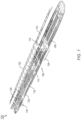
- an example embodiment of a passenger aircraft 100 may include overhead passenger rest cabins 102 and lower lobe passenger rest cabins 104.
- the aircraft 100 may include only overhead passenger rest cabins 102, only lower lobe passenger rest cabins 104, or both.
- Overhead passenger rest cabins 102 may be incorporated into the overhead crown area of the aircraft 100, above the main passenger cabin 106 (e.g., main deck) and the passenger seats 108, overhead bins 110, and monuments 112 (e.g., storage monuments, galley monuments, audio-visual monuments housing an inflight entertainment system, lavatories).
- main passenger cabin 106 e.g., main deck
- monuments 112 e.g., storage monuments, galley monuments, audio-visual monuments housing an inflight entertainment system, lavatories.
- Lavatories, monuments 112, zone dividers, or other structures proximate to the longitudinal center of the main passenger cabin 106 may be notched or otherwise modified to accommodate the overhead passenger rest cabin 102.
- lower lobe passenger rest cabins 104 may be incorporated on a cargo deck directly underneath the main passenger cabin 106.
- Passengers may access the overhead passenger rest cabins 102 or lower lobe passenger rest cabins 104 via an entry vestibule 114 located within the main passenger cabin 106.
- the vestibule 114 includes at least one staircase or ladder for accessing an overhead passenger rest cabin 102 or a lower lobe passenger rest cabin 104.
- the vestibule includes a first chamber with a first staircase for accessing the overhead passenger rest cabin 102 and a second chamber with a second staircase for accessing the lower lobe passenger rest cabin 104.
- the vestibule can include side-by-side chambers (e.g., separated by one or more wall structures) and/or vertically stacked chambers (e.g., separated the (first) staircase for accessing the overhead passenger rest cabin 102).
- the entry vestibule 114 may connect the overhead passenger rest cabins 102 and the lower lobe passenger rest cabins 104 (when both are incorporated within the aircraft 100) while providing a separate path for passengers to access each rest cabin from the main passenger cabin 106 (e.g., via ascending or descending staircases). It is contemplated that the entry vestibule 114 will be the primary means of passenger access to the overhead passenger rest cabins 102 and the lower lobe passenger rest cabins 104, and the sole means of access during non-emergency conditions.
- the entry vestibule 114 may be located at the aft end of the overhead passenger rest cabin 102, and an auxiliary vestibule (114a) may provide a secondary entrance and exit to and from the main passenger cabin 106 and the overhead passenger rest cabin 102.
- the overhead passenger rest cabins 102 may include additional escape hatches (not shown) providing an emergency escape route (e.g., to main aisles 116 of the main passenger cabin 106) for passengers to rapidly exit the overhead passenger rest cabins.
- the lower lobe passenger rest cabins 104 may similarly include escape hatches for emergency return to the main passenger cabin 106.
- the aircraft 100 may incorporate additional lower lobe rest compartments 118 situated on the lower cargo deck.
- the additional lower lobe rest compartments may be located substantially underneath selected partitioned premium seats 120 or premium compartments 122 in premium seating sections of the aircraft 100 and accessible to the occupants of said premium seats or premium compartments (e.g., during safe cruising segments) via proximate hatches in the main deck floor.
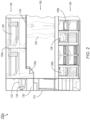
- the passenger aircraft 100a may be implemented and may function similarly to the aircraft 100 of FIG. 1 , except that the aircraft 100a may include an overhead passenger rest cabin 102 and a lower lobe passenger rest cabin 104 connected by an entry vestibule 114 to the main passenger cabin 106.
- the overhead passenger rest cabin 102 may be incorporated into remote space above the main passenger cabin 106 such that the floor of the central corridor 124 of the overhead passenger rest cabin corresponds substantially to the ceiling of the main passenger cabin 106 (e.g., over the centermost portion of the main cabin).
- the height of the overhead passenger rest cabin 102 that a passenger 126 of average height may remain comfortably standing, e.g., in a main aisle 118 ( FIG. 1 ) of the main passenger cabin.
- the overhead passenger rest cabin 102 may include individual passenger rest compartments 128 or bunks extending along either side of the central corridor 124, substantially parallel to the longitudinal or roll axis of the aircraft 100a.
- the overhead passenger rest cabin 102 may include a transitional space 130 between the entry vestibule 114 and the central corridor 122; the transitional space may include emergency equipment storage 132 and an emergency handset 134 for communicating with the cockpit or cabin crew, or additional steps 130a linking the entry vestibule and the central corridor.
- the lower lobe passenger rest cabin 104 may incorporate individual passenger rest compartments 128 aligned substantially parallel to the roll axis as well as passenger rest compartments 128a aligned at an angle to the roll axis, e.g., perpendicular to the roll axis or substantially parallel to the pitch axis of the aircraft 100a.
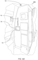
- the passenger rest compartment 128b (bunk) may be implemented and may function similarly to the passenger rest compartments 128, 128a of FIG. 2 , except that the passenger rest compartment 128b may include a safety belt 136, a privacy partition 138 (e.g., privacy curtain), ambient lighting 140, interior stowage compartments 142, an emergency oxygen drop 144, ventilated shoe stowage compartments 146 (which may, for example, be situated or accessed immediately outside or adjacent to the rest compartment), and a passenger service unit 148 (PSU).
- a safety belt 136 e.g., a privacy partition 138 (e.g., privacy curtain), ambient lighting 140, interior stowage compartments 142, an emergency oxygen drop 144, ventilated shoe stowage compartments 146 (which may, for example, be situated or accessed immediately outside or adjacent to the rest compartment), and a passenger service unit 148 (PSU).
- a privacy partition 138 e.g., privacy curtain
- ambient lighting 140
- the PSU 148 may be positioned proximate to the head end of the rest compartment 128b (e.g., where a pillow 150 may be provided for the passenger's head).
- the PSU 148 may include a positionable reading light 152 and gasper outlet 154, temperature controls 156, a panic/crew call button 158, lighted signage 160 (e.g., signaling the occupying passenger to return to his/her seat, fasten his/her safety belt 136, no smoking).
- the PSU may further include a speaker/microphone 162 and call button 164 allowing private two-way audio communication between the occupying passenger and the cabin crew.
- the foot end of the passenger rest compartment 128b may include an air return 166 and one or more infrared sensors 168 (e.g., infrared camera(s), light emitting diode (LED) sensor(s)/sensor array(s), or the like, operating in the infrared illumination spectrum (e.g., 700 nm - 1000 nm)).
- infrared sensors 168 e.g., infrared camera(s), light emitting diode (LED) sensor(s)/sensor array(s), or the like, operating in the infrared illumination spectrum (e.g., 700 nm - 1000 nm)).
- the passenger rest compartment 128b may include additional sensors or devices for monitoring passenger status, for example, a safety belt monitor 137 for detecting buckled/unbuckled status of the safety belt 136, a force sensor 178 in the bed 129 for detecting a weight of the passenger and other contents disposed in the passenger rest compartment 128b, a visual camera 180 (which, in some configurations, may be selectively enabled/disabled, as described below), and/or a hazard detector 182 (e.g., a smoke detector, a carbon monoxide detector, a radiation detector, an electric field detector, and/or a magnetic field detector, or the like).
- a safety belt monitor 137 for detecting buckled/unbuckled status of the safety belt 136
- a force sensor 178 in the bed 129 for detecting a weight of the passenger and other contents disposed in the passenger rest compartment 128b
- a visual camera 180 which, in some configurations, may be selectively enabled/disabled, as described below
- the passenger rest compartment 128b can also include an inflight entertainment display and/or a virtual window, e.g., as described in U.S. Patent Application Serial No. 16/126,952, Attorney Docket MA218-03, filed September 10, 2018 .
- the sensory devices e.g., infrared sensor 168, force sensor 178, camera 180, hazard detector 182, safety belt monitor 137, etc.
- PSU 148 display/virtual window, and other electronics in each passenger rest compartment 128b are input/output devices of a passenger rest cabin monitoring system, such as the passenger rest cabin monitoring system 200 described below.
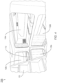
- the lower lobe passenger rest cabin 104b may be implemented and may function similarly to the lower lobe passenger rest cabin 104 of FIG. 2 , except that the lower lobe passenger rest cabin 104b may be accessed by a descending staircase 170 connecting the lower lobe passenger rest cabin to the entry vestibule 114 ( FIG. 2 ) and thereby to the main passenger cabin 106.
- the staircase 170 may descend into the center of the lower lobe passenger rest cabin 104b at a predetermined angle.
- the passenger rest compartments 128c-e may be implemented and may function similarly to the passenger rest compartments 128b of FIGS.
- the passenger rest compartments 128c, 128 e and the passenger rest compartment 128d may be respectively oriented substantially parallel or at an angle to (e.g., substantially perpendicular to) the longitudinal/roll axis of the aircraft 100 ( FIG. 1 ) and positioned around the perimeter of the lower lobe passenger rest cabin 104b.
- the passenger rest compartments 128d may be positioned in substantially vertical stacks of two or more bunks, depending on the height of the bunks relative to the height of the lower lobe passenger rest, cabin 104b.
- the passenger rest compartment 128e for example, may be stacked atop the passenger rest compartment 128c in a staggered fashion, set back from the passenger rest compartment 128 by a shelf 172.
- the passenger rest compartment 128e may combine space from two adjacent modular lower lobe passenger rest cabins 104b, where neither rest cabin on its own may include sufficient space for a full passenger rest compartment.
- Lower lobe passenger rest cabins 104, 104a may be proportioned for a form factor compatible with standard cargo containers; individual lower lobe passenger rest cabins may be palletized or otherwise capable of addition to, or removal from, the aircraft 100 via the existing cargo loading/unloading system.
- the aircraft 100 may incorporate lower lobe passenger rest cabins (104a) either forward or aft of the lower lobe passenger rest cabin 104 connected to the main passenger cabin 106 via the entry vestibule 114.
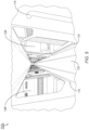
- the overhead passenger rest cabin 102a and individual rest compartments 128f may be implemented and may function similarly to the overhead passenger rest cabin 102 of FIG. 2 and the individual rest compartments 128c-e of FIG. 4 , except that the individual passenger rest compartments 128f of the overhead passenger rest cabin 102a may be sequentially arranged along either side of the central corridor 124 extending forward (e.g., substantially parallel to the longitudinal/roll axis of the aircraft 100 ( FIG. 1 )).
- the overhead passenger rest cabin 102a may comprise twenty (20) passenger rest compartments 128f: ten compartments on the port side of the central corridor 124 and ten opposite compartments on the starboard side.
- the transitional space 130 ( FIG.
- graspable handles 176 may be spaced along the central corridor 124; passengers 126a ( FIG. 2 ) traversing the central corridor (e.g., after entering the overhead passenger rest cabin 102a via the entry vestibule 114 and proceeding to their assigned passenger rest compartment 128f) may use the graspable handles to reduce strain while traversing the central corridor in a crouched position.
- a crew station 178 may be located at the forward end of the overhead passenger rest cabin 102 (including, e.g., emergency storage for first aid and fire containment supplies, communications facilities, and/or temporary jump seating). Similar crew stations may be located within the transitional space (130, FIG. 2 ) at the aft end of the overhead passenger rest cabin 102 and throughout the lower lobe passenger rest cabin (104, FIG. 4 ; e.g., proximate to the staircase or the point at which the entry vestibule 114 enters the lower lobe passenger rest cabin).
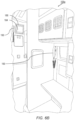
- the main passenger cabin 106a may be implemented and may function similarly to the passenger cabin 106 of FIGS. 1 and 2 , except that the passenger cabin 106a may include one or more displays 184, speakers 188, and two-way communication devices 190 (e.g., wired/wireless handsets, speaker phones, etc.) for providing alerts/notifications and communications for flight attendants.
- a display 184 e.g., LED/LCD display, or the like
- the display 184 can be mounted to an articulating base 186 that can swivel, tilt, turn, and/or deploy to make the display 184 easier to view by a flight attendant.
- the display 184 can be used to show statuses and/or images of passenger rest compartments 128, messages, alerts, notifications, and so forth.
- the display 184 may be mounted on a wall opposite a flight attendant chair (e.g., deployable/stowable chair) so that the display 184 is in direct view of a seated flight attendant.
- a flight attendant chair e.g., deployable/stowable chair
- Speakers 188 may be disposed throughout the passenger cabin 106a for providing audible alerts (e.g., chimes, broadcast messages, etc.). These speakers 188 may be part of an aircraft system and/or part of a monitoring system integrated within the aircraft. In some implementations, different audible alerts (e.g., different chimes) can be associated with different types of alerts (e.g., passenger discomfort, fire/excessive heat, unauthorized passenger activity, etc.). Cabin lighting may also be used to indicate different types of alerts, for example, by changing color and/or intensity of cabin lighting to provide a notification or indicate a critical status (e.g., fire, explosion, passenger threat, or other hazard).
- a critical status e.g., fire, explosion, passenger threat, or other hazard
- Flight attendant stations can also include two-way communication devices 190 (e.g., wired/wireless handsets) that enable flight attendants to communicate with other flight attendant stations (e.g., with other communication devices 190) and/or passenger rest compartments 128 (e.g., with PSUs 148).
- the two-way communication devices 190 may also be used by flight attendants to broadcast messages through the speakers 188.
- the two-way communication devices 190 can also be used for private communications over dedicated channels that connect the two-way communication devices 190 with individual PSUs 148 in respective ones of the passenger rest compartments 128.
- the one or more displays 184, speakers 188, and two-way communication devices 190 are input/output devices of a flight attendant information system, such as the flight attendant information system 210 described below.
- the flight attendant information system 210 may be integrated with and/or configured to communicate with the passenger rest cabin monitoring system 200.
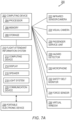
- FIG. 7A illustrates an example embodiment of a passenger rest cabin monitoring system 200 that can be implemented in the aircraft 100/100a described above.
- the passenger rest cabin monitoring system 200 includes infrared sensors/cameras 222 (e.g., infrared sensors 168) disposed in respective passenger rest, compartments 128 and a computing device 202 in communication with the infrared sensors/cameras 222.
- the computing device 202 may include at least one processor 204, at least one memory 206, and at least one storage device 208, as well as other components, equipment, and/or devices commonly included in a computing device, some or all of which may be communicatively coupled.
- the processor 204 may be implemented as any suitable processor, such as a single-core or multi-core processor, micro-controller, field programmable gate array (FPGA), or any other programmable logic device/controller (PLD/PLC).
- the processor 204 may be configured to run various software applications or computer code stored (e.g., maintained) in a non-transitory computer-readable medium (e.g., memory 206 and/or storage 208) and configured to execute various instructions or operations.
- the computing device 202 may be implemented as any suitable computing device. In some embodiments, the computing device 202 is implemented as a vetronics computing device (e.g., an avionics computing device) in a vehicle, such as an aircraft or automobile.
- the computing device 202 or the processor 204 may be implemented as a special purpose computer or a special purpose processor configured (e.g., programmed) to execute instructions for performing any or all of the operations disclosed throughout.
- the system 200 of FIG. 7A may include any suitable number of computing devices 202. While the computing device 202 exemplarily includes elements as shown, in some embodiments, one or more of the elements of the computing device 202 may be omitted, or the computing device 202 may include other elements.
- the computing device 202 can be configured to detect a presence of an individual (e.g., a passenger) in a passenger rest compartment 128 based on one or more measurements or thermal images generated by a respective infrared sensor/camera 222 of the passenger rest compartment 128. For example, in embodiments, the computing device 202 is configured to detect the presence of an individual when a measured temperature of the passenger rest compartment 128 exceeds a predetermined threshold temperature (e.g., at least 95°F, 35°C) or by identifying a heat signature of an individual in one or more thermal images generated by the infrared sensor/camera 222. In some embodiments, the computing device 202 may include a heat signature database in its storage 208.
- a predetermined threshold temperature e.g., at least 95°F, 35°C
- the computing device 202 may include a heat signature database in its storage 208.
- the heat signature database can include a plurality of heat signatures (e.g., heat distributions/maps and/or temperature thresholds) that correspond to humans, animals, and/or events (e.g., fire, lithium battery runaway temperature, explosion, etc.).
- the computing device 202 may be configured to detect heat signatures by comparing one or more thermal images captured by the infrared sensor/camera 222 to the heat signatures stored in the heat signature database.
- the computing device 202 may be in communication with a flight attendant information system 210 and configured to display an indication of the presence of the individual in the passenger rest compartment 128 via at least one display 214 (e.g., display 184) of the flight attendant information system 210.
- the flight attendant information system 210 includes a respective computing device 212, which may include a respective processor and memory and/or storage in a similar component configuration to that of computing device 202.
- computing device 202 replaces computing device 212 and is the primary computing device for the passenger rest cabin monitoring system 200 and the flight attendant information system 210 (which may be integrated into one system, e.g., system 200).
- the flight attendant information system 210 includes one or more displays 214 (e.g., displays 184), one or more speakers 216 (e.g., speakers 188), a light system 218 (including lighted signage, indicator lights, and/or general cabin lighting), and one or more communication devices 220 (e.g., two-way communication devices 190).
- the flight attendant information system 210 may be integrated with and/or configured to access components of a primary aircraft system.
- the flight attendant information system 220 may be configured to utilize existing lighting, speaker systems, displays, hazard detectors (e.g., smoke and/or carbon monoxide detectors, excessive heat/fire detectors, etc.), alarms, and other components of the primary aircraft system.
- hazard detectors e.g., smoke and/or carbon monoxide detectors, excessive heat/fire detectors, etc.
- the computing device 202 can be further configured to detect a presence of a second individual with the individual (e.g., the presence of two or more passengers) in a passenger rest compartment 128 based on one or more thermal images generated by a respective infrared sensor/camera 222 of the passenger rest compartment 128.
- the computing device 202 may be configured to detect the presence of two or more individuals in a passenger rest compartment 128 by identifying heat signatures of the individuals in one or more thermal images generated by the infrared sensor/camera 222.
- the computing device 202 may be configured to display an indication of the presence of two or more individuals in the passenger rest compartment 128 via at least one display 214 (e.g., display 184) of the flight attendant information system 210.
- the passenger rest compartments in most cases, will be designed to accommodate a single passenger occupant.
- the computing device 202 can be configured to provide an audible alert (e.g., alarm/chime via the speaker 216) and/or a visual alert (e.g., via the display 214 or light system 218) via the flight attendant information system 210 to indicate the (unauthorized) presence of the second individual with the individual in the passenger rest compartment 128.
- the computing device 202 can also be configured to provide an audible alert (e.g., alarm/chime via the speaker 216) and/or a visual alert (e.g., via the display 214 or light system 218) via the flight attendant information system 210 to indicate the unauthorized presence of an individual in a passenger rest compartment 128 when the passenger rest compartment 128 has not been reserved for use by the individual.
- an audible alert e.g., alarm/chime via the speaker 216
- a visual alert e.g., via the display 214 or light system 218
- the computing device 202 may be configured to monitor temperatures in respective passenger rest compartments 128 and/or other portions (e.g., corridor) of the passenger rest cabin 102/104 to detect excessive heat or drops in temperature that may indicate danger.
- the computing device 202 can be configured to detect whether a passenger rest compartment temperature is above or below a predetermined critical (e.g., maximum/minimum operating) temperature based on one or more measurements or thermal images generated by a respective infrared sensor/camera 222 of the passenger rest compartment 128.
- a predetermined critical e.g., maximum/minimum operating
- the computing device 202 can be configured to provide an audible alert (e.g., alarm/chime via the speaker 216) and/or a visual alert (e.g., via the display 214 or light system 218) via the flight attendant information system 210 to indicate a critical status (e.g., perceived danger or situation warranting action by one or more flight attendants) of the passenger rest compartment 128 when the passenger rest compartment temperature is above a predetermined (maximum) critical temperature, or similarly if the passenger rest compartment temperature is below a predetermined (minimum) critical temperature.
- a critical status e.g., perceived danger or situation warranting action by one or more flight attendants
- the computing device 202 is configured to detect a temperature of a portion of (e.g., (e.g., a specific location/area within) passenger rest compartment or common area (e.g., vestibule 114 or corridor of the passenger rest cabin 102/104) based on one or more thermal images generated by a respective infrared sensor/camera 222 of the passenger rest compartment 128.
- the computing device 202 can be further configured to compare the temperature of the portion of the passenger rest compartment 128 (or passenger rest cabin 102/104 common area) with a predetermined critical temperature.
- the predetermined critical temperature is associated with the runaway temperature for an energy storage device (e.g., 260° F (127°C) for a lithium battery).
- the predetermined critical temperature can be the runaway temperature or a temperature (e.g., 200°F (93°C), 210°F (99°C), 220°F (104°C), 230°F (110°C), 240°F (116°C), 250°F (121 °C), or the like) that is below the runaway temperature but indicative of potential approach to the runaway temperature.
- the predetermined critical temperature may be associated with a combustion temperature, fire (e.g., in the range of 500°F (260°C) to 1500°F (816°C)), excessive radiation, or the like.
- the computing device 202 can be configured to provide an audible alert (e.g., alarm/chime via the speaker 216) and/or a visual alert (e.g., via the display 214 or light system 218) via the flight attendant information system 210 to indicate a critical status of the passenger rest compartment 128 when the detected temperature of the portion of the passenger rest compartment 128 (or passenger rest cabin 102/104 common area) is above the predetermined critical temperature.
- the computing device 202 may be further configured to display the location of the portion of the passenger rest compartment via at least one display 214 of the flight attendant information system 210 when the temperature of the portion of the passenger rest compartment 128 (or passenger rest cabin 102/104 common area) is above the predetermined critical temperature.
- the computing device 202 can be configured to help in early fire detection/prediction (e.g., by detecting or predicting the presence of a fire before a smoke detector or ambient heat sensor would be capable of doing so) in the passenger rest compartment 128 or common area of the passenger rest cabin 102/104.
- the computing device 202 is configured to display to provide a fire prediction alert (e.g., an audible alert (e.g., alarm/chime via the speaker 216) and/or a visual alert (e.g., via the display 214 or light system 218) via the flight attendant information system 210) based on the detected temperature of the portion of the passenger rest compartment 128 (or passenger rest cabin 102/104 common area) and the location of the portion of the passenger rest compartment 128 (or passenger rest cabin 102/104 common area).
- the computing device 202 may also have emergency/crisis guidance instructions, escape routes, and/or other emergency guidance information in the storage 208.
- the computing device 202 may be configured to display emergency guidance information via at least one display 214 of the flight attendant information system 210 based on the detected temperature of the portion of the passenger rest compartment 128 (or passenger rest cabin 102/104 common area) and the location of the portion of the passenger rest compartment 128 (or passenger rest cabin 102/104 common area) where the critical temperature is detected.
- the computing device 202 can be configured to detect whether a change (increase/decrease) in temperature of a passenger rest compartment 128 is above or below a predetermined critical change in temperature based on a plurality of measurements or thermal images generated by a respective infrared sensor/camera 222 of the passenger rest compartment 128.
- the computing device 202 can be configured to provide an audible alert (e.g., alarm/chime via the speaker 216) and/or a visual alert (e.g., via the display 214 or light system 218) via the flight attendant information system 210 to indicate a critical status (e.g., perceived danger or situation warranting action by one or more flight attendants) of the passenger rest compartment 128 when the change in temperature is exceeds the predetermined critical change in temperature (e.g., when the temperature increases or decreases by more than N degrees, or too quickly (e.g., more an N degrees/t seconds)).
- a critical status e.g., perceived danger or situation warranting action by one or more flight attendants
- the passenger rest cabin monitoring system 200 may further include visual cameras 224 (e.g., cameras 180 that detect light in the visible illumination spectrum (e.g., 400 nm - 700 nm)) disposed in the passenger rest compartments 128, the vestibule 114, or other portions (e.g., corridor) of the passenger rest cabin 102/104.
- the visual cameras 224 are only employed in the common areas (e.g., vestibule 114 and corridor of a passenger rest cabin 102/104). In other embodiments, visual cameras 224 are also installed in each of the passenger rest compartments 128.
- the computing device 202 can be communicatively coupled to the visual cameras 224 and configured to record one or more images of a passenger rest compartment 128 (or passenger rest cabin 102/104 common area) with a respective visual camera 224.
- the visual cameras 224 can be selectively enabled to record images (e.g., during takeoff /landing to make sure no passengers are in the rest cabin 102/104, when danger/critical events are detected, and the like).
- the computing device 202 may detect a critical status (e.g., excessive heat, unauthorized occupancy of a passenger rest compartment, etc.) of the passenger rest compartment based on one or more measurements or thermal images generated by a respective infrared sensor/camera 222 of the passenger rest compartment 128, and can be configured to record one or more images of the passenger rest compartment 128 with a respective visual camera 224 of the passenger compartment 128 when the critical status is detected.
- the computing device 202 can also be configured to cause the flight attendant information system 210 to display the recorded images of the passenger rest compartment 128 via the display (or displays) 214 (e.g., displays 184) of the flight attendant information system 210.
- the computing device 202 is further configured to detect whether a passenger activity state (e.g., movement) is above or below a predetermined critical activity state based on one or more thermal images generated by a respective infrared sensor/camera 222 of the passenger rest compartment 128 (or passenger rest cabin 102/104 common area) or one or more images of the passenger rest compartment 128 recorded by a respective visual camera 224 of the passenger rest compartment 128 (or passenger rest cabin 102/104 common area).
- the computing device 202 may be configured to detect one or more passenger gestures based on one or more images recorded by a respective visual camera 224 of the passenger rest compartment 128 (or passenger rest cabin 102/104 common area).
- the computing device 202 includes a plurality of critical passenger gestures that may indicate a crisis or other situation requiring flight attendant intervention in a database in the storage 208.
- the computing device 202 may be configured to detect a critical passenger gesture based on the one or more images recorded by the respective visual camera 224 and provide an audible alert (e.g., alarm/chime via the speaker 216) and/or a visual alert (e.g., via the display 214 or light system 218) via the flight attendant information system 210 to indicate a critical passenger status when the one or more passenger gestures correspond to one or more predetermined critical passenger gestures (e.g., rapid/frantic movement, seizing, waving/flailing of arms, punching, kicking, etc.).
- the computing device 202 can also be configured to detect one or more passenger facial expressions based on one or more images recorded by a respective visual camera 224.
- the computing device 202 may include a plurality of critical passenger facial expressions that may indicate a crisis or other situation requiring flight attendant intervention in a database in the storage 208.
- the computing device 202 can be configured to detect a critical passenger facial expression based on the one or more images recorded by the respective visual camera 224 and provide an audible alert (e.g., alarm/chime via the speaker 216) and/or a visual alert (e.g., via the display 214 or light system 218) via the flight attendant information system 210 to indicate a critical passenger status when the one or more passenger gestures correspond to one or more predetermined critical passenger facial expressions (e.g., choking, gagging, excessive coughing or apparent discomfort, anger, etc.).
- an audible alert e.g., alarm/chime via the speaker 21
- a visual alert e.g., via the display 214 or light system 218
- the flight attendant information system 210 e.g., choking, gagging, excessive coughing or apparent discomfort, anger, etc.
- the presence of an individual in a passenger rest compartment 128 and/or motion can additionally/alternatively be detected by one or more force sensors 234 (e.g., force sensor 178) in a passenger rest compartment 128 (e.g., integrated within the bed 129).
- the computing device 202 can be configured to provide an audible alert (e.g., alarm/chime via the speaker 216) and/or a visual alert (e.g., via the display 214 or light system 218) via the flight attendant information system 210 to indicate a critical activity state (e.g., little to no movement or overactive passenger) within the passenger rest compartment 128 when the detected passenger activity state is above the predetermined critical activity state.
- a critical activity state e.g., little to no movement or overactive passenger
- the computing device 202 can also be configured to monitor sound/noise levels in the passenger rest compartments 128.
- the passenger rest compartments 128 or other portions (e.g., corridor) of the passenger rest cabin 102/104 can include microphones 230 for monitoring sound/noise levels.
- a microphone 230 e.g., microphone 162 is part of a PSU 226 (e.g., PSU 148) in the passenger rest compartment 128.
- the microphone 230 is dedicated to sound/noise level monitoring, for example, a camera 222/224 may be equipped with or proximate to the microphone 230.
- the computing device 202 may be configured to detect a critical status (e.g., perceived danger or situation warranting action by one or more flight attendants) of a passenger rest compartment 128 when the passenger rest compartment sound/noise level detected by a respective microphone 230 of the passenger rest compartment 128 exceeds a predetermined critical noise level.
- the computing device 202 can be configured to record one or more images of the passenger rest compartment 128 with a respective visual camera 224 of the passenger compartment 128 when the critical status is detected, and can be further configured to display the recorded images of the passenger rest compartment 128 via at least one display 214 (e.g., display 184) of the flight attendant information system 210.
- the computing device 202 may additionally/alternatively be configured to provide an audible alert (e.g., alarm/chime via the speaker 216) and/or a visual alert (e.g., via the display 214 or light system 218) via the flight attendant information system 210 to indicate a critical status (e.g., perceived danger or situation warranting action by one or more flight attendants) of the passenger rest compartment 128 when the passenger rest compartment noise level exceeds the predetermined critical noise level.
- an audible alert e.g., alarm/chime via the speaker 216
- a visual alert e.g., via the display 214 or light system 218
- the flight attendant information system 210 to indicate a critical status (e.g., perceived danger or situation warranting action by one or more flight attendants) of the passenger rest compartment 128 when the passenger rest compartment noise level exceeds the predetermined critical noise level.
- a critical status e.g., perceived danger or situation warranting action by one or more flight attendants
- the passenger rest cabin monitoring system 200 can further include at least one hazard detector 228 (e.g., hazard detector 182) in respective ones of the passenger rest compartments 128 or in another portion (e.g., corridor) of the passenger rest cabin 102/104.
- the hazard detector 228 can include, but is not limited to, a smoke detector, a carbon monoxide detector, a radiation detector, an electric field detector, a magnetic field detector, or any combination thereof.
- one or more hazard detectors 228 and/or alarms are part of the primary aircraft system, and the passenger rest cabin monitoring system 200 can be configured to access these detectors 228 and/or alarms.
- the passenger rest cabin monitoring system 200 includes hazard detectors 228 and/or alarms that are separate from or added on to/integrated with the primary aircraft system components.
- the computing device 202 can be in communication with the hazard detector 228 (or multiple hazard detectors 228) and configured to detect a critical status (e.g., perceived danger or situation warranting action by one or more flight attendants) when a hazard is detected by a respective hazard detector 228 of a passenger rest compartment 128 or common area of the passenger rest cabin 102/104.
- a critical status e.g., perceived danger or situation warranting action by one or more flight attendants
- the computing device 202 can be configured to provide an audible alert (e.g., alarm/chime via the speaker 216) and/or a visual alert (e.g., via the display 214 or light system 218) via the flight attendant information system 210 to indicate a critical status (e.g., perceived danger or situation warranting action by one or more flight attendants) of the passenger rest compartment 128 when a hazard is detected.
- a visual camera 224 may be in proximity to (e.g., in the same general location/zone) as a respective hazard detector 228, and the computing device 202 can be configured to record one or more images with the visual camera 224 when the hazard/critical status is detected by the hazard detector 228.
- the computing device 202 may be further configured to display the recorded images via one or more displays 214 of the flight attendant information system 210.
- the passenger rest cabin monitoring system 200 includes or is connected with PSUs 226 (e.g., PSUs 148) in the passenger rest compartments 128.
- PSUs 226 e.g., PSUs 148, in the passenger rest compartments 128.
- each PSU 226 may include an attendant call button 240 (e.g., attendant call button 164), a panic/crew call button 242 (e.g., panic/crew call button 158), and a two-way communication device 244 (e.g., speaker/microphone 162) that are communicatively coupled to the computing device 202.
- the computing device 202 may be configured to receive a passenger communication or alert from a respective PSU 226 of a passenger rest compartment 128 and configured to provide an audible alert (e.g., alarm/chime via the speaker 216) and/or a visual alert (e.g., via the display 214 or light system 218) via the flight attendant information system 210 to indicate that a passenger communication or alert has been received from the passenger rest compartment 128.
- a flight attendant may then respond to alert and/or communicate with the passenger using a communication device 220 (e.g., communication device 190) of the flight attendant information system 210.
- the flight attendant communication device 220 and the passenger communication device 244 may be configured to communicate (privately) over a dedicated communication channel.
- each passenger rest compartment 128 is equipped with a passenger communication device 244 that can be used for private communications with the flight attendants/flight crew (e.g., via communication with the flight attendant communication device 220).
- the computing device 202 is further configured to communicate safety belt statuses to the flight attendant information system 210 based on information received from safety belt monitors 232 (e.g., safety belt monitors 137), which may be integrated within the buckles or elsewhere for safety belts 136 in the passenger rest compartments 128.
- the computing device 202 may be configured to receive a safety belt status (e.g., buckled/unbuckled or secured/unsecured status) from a safety belt monitor 232 of a respective passenger rest compartment 128.
- the computing device 202 can be configured to provide an audible alert (e.g., alarm/chime via the speaker 216) and/or a visual alert (e.g., via the display 214 or light system 218) via the flight attendant information system 210 to notify flight attendants that a safety belt 136 is unbuckled/unsecured in an occupied passenger rest compartment 128.
- an audible alert e.g., alarm/chime via the speaker 216
- a visual alert e.g., via the display 214 or light system 218
- virtual windows 236 and/or inflight entertainment display devices are located in the passenger rest compartments 128.
- the computing device 202 may be configured to activate a respective virtual window 236 of the passenger rest compartment 128 based on the detected presence of the individual in the passenger rest compartment 128, for example, based on one or more measurements or thermal images generated by a respective infrared sensor/camera 222 of the passenger rest compartment 128, and/or based on weight/movement measurements detected by a respective force sensor 234 of the passenger rest compartment 128.
- the computing device 202 and/or the virtual window 236 can be implemented and configured as described in U.S. Patent Application Serial No. 16/126,952, Attorney Docket MA218-03, filed September 10, 2018 .
- the passenger rest cabin monitoring system 200 may further include or can be configured to communication with the flight attendant/cabin crew's portable electronic devices 238 (e.g., smartphones, tablets, wearables (e.g., activity trackers, pendants, smart watches).
- the flight attendant/cabin crew's portable electronic devices 238 e.g., smartphones, tablets, wearables (e.g., activity trackers, pendants, smart watches).
- any of the audible or visual alerts output via the flight attendant information system 210 may be additionally or alternatively provided via at least one portable electronic device 238.
- a flight attendant may employ his/her portable electronic device 238 instead of or in addition to the communication device 220 for two-way (private) communications with PSUs 226 of the passenger rest compartments 128 and/or to broadcast messages or information (e.g., via the aircraft speaker system).
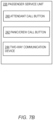
- the computing device 202 is configured to receive "opt in” or “opt out” requests for passengers (e.g., via the passenger's PSU 226 or via a flight attendant input to the flight attendant information system 210). The requests can be for selectively disabling some or all of the monitoring equipment in a particular passenger rest cabin 128.
- some of the monitoring equipment e.g., the infrared camera/sensor 222, hazard detector 228, safety belt monitor 232, and/or other equipment that does not intrude on the passenger's privacy
- other monitoring equipment e.g., visual camera 224, microphone 230, force sensor 234, and/or other equipment that may intrude on the passenger's privacy
- At least one non-transitory computer-readable medium may refer to as at least one non-transitory computer-readable medium (e.g., memory 206, storage 208 or a combination thereof; e.g., at least one computer-readable medium implemented as hardware; e.g., at least one non-transitory processor-readable medium, at least one memory (e.g., at least one nonvolatile memory, at least one volatile memory, or a combination thereof; e.g., at least one random-access memory, at least one flash memory, at least one read-only memory (ROM) (e.g., at least one electrically erasable programmable read-only memory (EEPROM)), at least one on-processor memory (e.g., at least one on-processor cache, at least one on-processor buffer, at least one on-processor flash memory, at least one on-processor EEPROM, or a combination thereof), or a combination thereof), at least one on-processor memory (e.g., at least one on
- embodiments of the methods according to the inventive concepts disclosed herein may include one or more of the steps described herein. Further, such steps may be carried out in any desired order and two or more of the steps may be carried out simultaneously with one another. Two or more of the steps disclosed herein may be combined in a single step, and in some embodiments, one or more of the steps may be carried out as two or more sub-steps. Further, other steps or sub-steps may be carried in addition to, or as substitutes to one or more of the steps disclosed herein.
Landscapes
- Engineering & Computer Science (AREA)
- Aviation & Aerospace Engineering (AREA)
- Physics & Mathematics (AREA)
- General Physics & Mathematics (AREA)
- Emergency Management (AREA)
- Business, Economics & Management (AREA)
- Theoretical Computer Science (AREA)
- General Engineering & Computer Science (AREA)
- Human Computer Interaction (AREA)
- Computer Hardware Design (AREA)
- Multimedia (AREA)
- Signal Processing (AREA)
- Alarm Systems (AREA)
- Aiming, Guidance, Guns With A Light Source, Armor, Camouflage, And Targets (AREA)
- Body Structure For Vehicles (AREA)
Claims (12)
- System zum Überwachen von Passagierruheabteilen, umfassend:einen Vorraum (114), der dazu eingerichtet ist, in einer Passagierkabine (106) eines Luftfahrzeugs angeordnet zu werden, wobei der Vorraum mindestens eine Treppe (170) beinhaltet, die für den Zugang zu einer Passagierruhekabine (102, 104) oberhalb oder unterhalb der Passagierkabine des Luftfahrzeugs bei Anordnung in der Passagierkabine eingerichtet ist;eine Vielzahl von Passagierruheabteilen (128), die dazu eingerichtet ist, in der Passagierruhekabine angeordnet zu werden, wobei die Passagierruheabteile Betten (129) beinhalten, dadurch gekennzeichnet, dass die Passagierruheabteile ferner Infrarotkameras (168), visuelle Kameras (224) und Passagierserviceeinheiten (148) beinhalten, wobei die visuellen Kameras in jeweiligen Abschnitten des Vorraums, einem Flur der Passagierkabine und jeweiligen einen der Passagierruheabteile angeordnet sind;ein Flugbegleiterinformationssystem (210), das mindestens eine Anzeige (184) und mindestens einen Lautsprecher (188) beinhaltet;eine Rechenvorrichtung (202) in Kommunikation mit den Infrarotkameras, den visuellen Kameras, den Passagierserviceeinheiten und dem Flugbegleiterinformationssystem, wobei die Rechenvorrichtung zu Folgendem konfiguriert ist:Erkennen einer Temperatur eines Abschnitts des Passagierruheabteils basierend auf einem oder mehreren Wärmebildern, die durch eine jeweilige Infrarotkamera des Passagierruheabteils generiert werden;Erkennen eines kritischen Status des Passagierruheabteils basierend auf einem oder mehreren Wärmebildern, die durch die jeweilige Infrarotkamera des Passagierruheabteils generiert werden;Aufnehmen von einem oder mehreren Bildern des Passagierruheabteils mit einer jeweiligen visuellen Kamera des Passagierabteils, wenn der kritische Status erkannt wird; undAnzeigen des einen oder der mehreren Bilder des Passagierruheabteils über die mindestens eine Anzeige des FlugbegleiterinformationssystemsVergleichen der Temperatur des Abschnitts des Passagierruheabteils mit einer vorbestimmten kritischen Temperatur, wobei die vorbestimmte kritische Temperatur mit einer Durchgehtemperatur einer Energiespeichervorrichtung verknüpft ist;Bereitstellen mindestens eines von einem akustischen Alarm oder einem visuellen Alarm über das Flugbegleiterinformationssystem, um einen kritischen Status des Passagierruheabteils anzugeben, wenn die Temperatur des Abschnitts des Passagierruheabteils oberhalb der vorbestimmten kritischen Temperatur liegt;
undein virtuelles Fenster, das mit mindestens einigen der Vielzahl von Passagierruheabteilen verknüpft ist. - System nach Anspruch 1, wobei die Rechenvorrichtung (202) ferner zu Folgendem konfiguriert ist:
Anzeigen des Standorts des Abschnitts des Passagierruheabteils über die mindestens eine Anzeige des Flugbegleiterinformationssystems, wenn die Temperatur des Abschnitts des Passagierruheabteils oberhalb der vorbestimmten kritischen Temperatur liegt. - System nach Anspruch 2, wobei die Rechenvorrichtung (202) ferner zu Folgendem konfiguriert ist:
Anzeigen eines Brandvorhersagealarms über die mindestens eine Anzeige des Flugbegleiterinformationssystems, basierend auf der erkannten Temperatur des Abschnitts des Passagierruheabteils und dem Standort des Abschnitts des Passagierruheabteils. - System nach Anspruch 2, wobei die Rechenvorrichtung (202) ferner zu Folgendem konfiguriert ist:
Anzeigen von Notfallanleitungsinformationen über die mindestens eine Anzeige des Flugbegleiterinformationssystems, basierend auf der erkannten Temperatur des Abschnitts des Passagierruheabteils und dem Standort des Abschnitts des Passagierruheabteils. - System nach einem der vorhergehenden Ansprüche, wobei die Rechenvorrichtung (202) ferner zu Folgendem konfiguriert ist:Erkennen einer Anwesenheit einer Person in einem Passagierruheabteil basierend auf einem oder mehreren Wärmebildern, die durch eine jeweilige Infrarotkamera des Passagierruheabteils generiert werden; undAnzeigen einer Angabe der Anwesenheit der Person in dem Passagierruheabteil über die mindestens eine Anzeige des Flugbegleiterinformationssystems.
- System nach einem der vorhergehenden Ansprüche, wobei die Rechenvorrichtung (202) ferner zu Folgendem konfiguriert ist:Erkennen, ob ein Passagieraktivitätszustand oberhalb oder unterhalb eines vorbestimmten kritischen Aktivitätszustands liegt, basierend auf einem oder mehreren Bildern, die durch eine jeweilige eine der Vielzahl von visuellen Kameras aufgenommen werden; undBereitstellen mindestens eines von einem akustischen Alarm oder einem visuellen Alarm über das Flugbegleiterinformationssystem, um einen kritischen Aktivitätszustand anzugeben, wenn der Passagieraktivitätszustand oberhalb des vorbestimmten kritischen Aktivitätszustands liegt.
- System nach einem der vorhergehenden Ansprüche, wobei die Rechenvorrichtung (202) ferner zu Folgendem konfiguriert ist:Erkennen einer oder mehrerer Passagiergesten basierend auf einem oder mehreren Bildern, die durch eine jeweilige eine der Vielzahl von visuellen Kameras aufgenommen werden; undBereitstellen mindestens eines von einem akustischen Alarm oder einem visuellen Alarm über das Flugbegleiterinformationssystem, um einen kritischen Passagierstatus anzugeben, wenn die eine oder die mehreren Passagiergesten einer oder mehreren vorbestimmten kritischen Passagiergesten entsprechen.
- System nach einem der vorhergehenden Ansprüche, wobei die Rechenvorrichtung (202) ferner zu Folgendem konfiguriert ist:Erkennen eines oder mehrerer Passagiergesichtsausdrücke basierend auf einem oder mehreren Bildern, die durch eine jeweilige eine der Vielzahl von visuellen Kameras aufgenommen werden; undBereitstellen mindestens eines von einem akustischen Alarm oder einem visuellen Alarm über das Flugbegleiterinformationssystem, um einen kritischen Passagierstatus anzugeben, wenn die eine oder die mehreren Gesichtsausdrücke einem oder mehreren vorbestimmten kritischen Passagiergesichtsausdrücken entsprechen.
- System nach einem der vorhergehenden Ansprüche, ferner umfassend zusätzliche Infrarotkameras (222), die in jeweiligen Abschnitten des Vorraums und des Flurs der Passagierkabine angeordnet sind, wobei die Rechenvorrichtung ferner zu Folgendem konfiguriert ist:Erkennen einer Temperatur eines Abschnitts des Vorraums oder des Flurs basierend auf einem oder mehreren Wärmebildern, die durch eine jeweilige eine der zusätzlichen Infrarotkameras generiert werden;Vergleichen der Temperatur des Abschnitts des Vorraums oder des Flurs mit einer vorbestimmten kritischen Temperatur; und Bereitstellen mindestens eines von einem akustischen Alarm oder einem visuellen Alarm über das Flugbegleiterinformationssystem, um einen kritischen Status des Passagierruheabteils anzugeben, wenn die Temperatur des Abschnitts des Passagierruheabteils oberhalb der vorbestimmten kritischen Temperatur liegt.
- System nach einem der vorhergehenden Ansprüche, wobei die Passagierruheabteile ferner Mikrofone (162) beinhalten, wobei die Rechenvorrichtung ferner zu Folgendem konfiguriert ist:Erkennen eines kritischen Status des Passagierruheabteils, wenn ein Geräuschpegel des Passagierruheabteils, der durch ein jeweiliges Mikrofon des Passagierruheabteils erkannt wird, einen vorbestimmten kritischen Geräuschpegel überschreitet; undBereitstellen mindestens eines von einem akustischen Alarm oder einem visuellen Alarm über das Flugbegleiterinformationssystem, um den kritischen Status des Passagierruheabteils anzugeben, wenn der Geräuschpegel des Passagierruheabteils den vorbestimmten kritischen Geräuschpegel überschreitet.
- System nach einem der vorhergehenden Ansprüche, ferner umfassend mindestens einen Gefahrenmelder (182) und mindestens eine visuelle Kamera in der Nähe des mindestens einen Gefahrenmelders, wobei die Rechenvorrichtung ferner zu Folgendem konfiguriert ist:Aufnehmen von einem oder mehreren Bildern mit der mindestens einen visuellen Kamera, wenn der kritische Status erkannt wird; undAnzeigen des einen oder der mehreren Bilder über die mindestens eine Anzeige des Flugbegleiterinformationssystems
- System nach einem der vorhergehenden Ansprüche, wobei die Rechenvorrichtung dazu konfiguriert ist, ein jeweiliges virtuelles Fenster des Passagierruheabteils basierend auf einer erkannten Anwesenheit der Person in dem Passagierruheabteil zu aktivieren.
Applications Claiming Priority (3)
| Application Number | Priority Date | Filing Date | Title |
|---|---|---|---|
| US201862729237P | 2018-09-10 | 2018-09-10 | |
| US16/126,981 US11136137B2 (en) | 2018-09-10 | 2018-09-10 | Non-intrusive passenger rest cabin monitoring system |
| PCT/US2019/050351 WO2020055826A1 (en) | 2018-09-10 | 2019-09-10 | Non-intrusive passenger rest cabin monitoring system |
Publications (3)
| Publication Number | Publication Date |
|---|---|
| EP3849902A1 EP3849902A1 (de) | 2021-07-21 |
| EP3849902A4 EP3849902A4 (de) | 2022-06-29 |
| EP3849902B1 true EP3849902B1 (de) | 2024-10-30 |
Family
ID=69720859
Family Applications (3)
| Application Number | Title | Priority Date | Filing Date |
|---|---|---|---|
| EP19890378.3A Active EP3850541B1 (de) | 2018-09-10 | 2019-09-10 | Flugzeuge mit passagierruheabteilen für abgelegene räume |
| EP19859994.6A Active EP3849902B1 (de) | 2018-09-10 | 2019-09-10 | Nicht intrusives überwachungssystem für passagierruhekabine |
| EP19860996.8A Pending EP3849904A4 (de) | 2018-09-10 | 2019-09-10 | Passagierruheabteile für abgelegene bereiche eines flugzeugs |
Family Applications Before (1)
| Application Number | Title | Priority Date | Filing Date |
|---|---|---|---|
| EP19890378.3A Active EP3850541B1 (de) | 2018-09-10 | 2019-09-10 | Flugzeuge mit passagierruheabteilen für abgelegene räume |
Family Applications After (1)
| Application Number | Title | Priority Date | Filing Date |
|---|---|---|---|
| EP19860996.8A Pending EP3849904A4 (de) | 2018-09-10 | 2019-09-10 | Passagierruheabteile für abgelegene bereiche eines flugzeugs |
Country Status (4)
| Country | Link |
|---|---|
| US (1) | US11136137B2 (de) |
| EP (3) | EP3850541B1 (de) |
| CN (3) | CN113286743B (de) |
| WO (1) | WO2020055826A1 (de) |
Families Citing this family (17)
| Publication number | Priority date | Publication date | Assignee | Title |
|---|---|---|---|---|
| US11273836B2 (en) | 2017-12-18 | 2022-03-15 | Plusai, Inc. | Method and system for human-like driving lane planning in autonomous driving vehicles |
| WO2020208505A1 (en) * | 2019-04-09 | 2020-10-15 | University Of North Texas | Skimmer detection wand |
| US11354948B2 (en) * | 2019-06-10 | 2022-06-07 | The Boeing Company | Methods and systems for performing maintenance on an aircraft |
| US11640723B2 (en) | 2020-10-20 | 2023-05-02 | Rosemount Aerospace Inc. | System and method for enhanced surveillance using video analytics |
| EP4019411B1 (de) * | 2020-12-23 | 2025-01-29 | B/E Aerospace, Inc. | Datengesteuertes verwaltungssystem und verfahren für fahrgastsicherheit, -gesundheit und -komfort |
| US11767117B2 (en) * | 2021-01-06 | 2023-09-26 | Toyota Boshoku Kabushiki Kaisha | Room for aircraft cabin |
| CN113062632A (zh) * | 2021-02-24 | 2021-07-02 | 八英里网络科技(广州)有限公司 | 一种休息舱 |
| US11731763B2 (en) * | 2021-06-03 | 2023-08-22 | Honeywell International Inc. | Methods and systems for identifying and addressing passenger issues in an aircraft |
| US12365462B2 (en) * | 2021-06-29 | 2025-07-22 | The Boeing Company | Emergency oxygen systems for internal cabins of aircraft |
| US11945588B2 (en) | 2021-09-28 | 2024-04-02 | The Boeing Company | Stowage bin assemblies for and a method for increasing overhead space and configurability in an internal cabin of a vehicle |
| CN114333238B (zh) * | 2021-12-30 | 2024-06-25 | 广东省第二人民医院(广东省卫生应急医院) | 一种基于5g的紧急救援通信系统 |
| US20230257119A1 (en) * | 2022-02-15 | 2023-08-17 | B/E Aerospace, Inc. | Use of forward closet in single aisle aircraft for wheelchair accommodation |
| CN114840917B (zh) * | 2022-04-14 | 2022-11-22 | 清华大学 | 灭火飞机安全约束边界构建方法及系统 |
| CN116107305A (zh) * | 2023-02-08 | 2023-05-12 | 烟台艾睿光电科技有限公司 | 一种机器人的巡检方法、装置、存储介质及机器人 |
| EP4470917A1 (de) * | 2023-05-31 | 2024-12-04 | Airbus Operations GmbH | Anzeigevorrichtung, flugzeugkabine und verfahren zur montage einer flugzeugkabine |
| WO2025073365A1 (en) * | 2023-10-05 | 2025-04-10 | Zodiac Cabin Controls Gmbh | Gesture recognition system |
| US12469297B2 (en) * | 2023-11-13 | 2025-11-11 | Kimai Dosch | Low-gravity safety event detection |
Citations (1)
| Publication number | Priority date | Publication date | Assignee | Title |
|---|---|---|---|---|
| CN108332860A (zh) * | 2018-03-16 | 2018-07-27 | 南京工业大学 | 基于红外热成像技术的锂离子电池组热失控自动监测方法 |
Family Cites Families (66)
| Publication number | Priority date | Publication date | Assignee | Title |
|---|---|---|---|---|
| US3144224A (en) | 1962-09-28 | 1964-08-11 | Dee B Carroll | Escape hatches for passenger airliner |
| US5784836A (en) | 1994-11-03 | 1998-07-28 | Be Aerospace, Inc. | Demountable comfort modules for passenger aircraft |
| DE19502658C1 (de) | 1995-01-28 | 1996-03-28 | Daimler Benz Aerospace Airbus | Anordnung zum Versorgen von Passagieren in einer Passagierkabine, insbesondere in einem Flugzeug |
| US6393343B1 (en) | 1997-03-13 | 2002-05-21 | Airbus Deutschland Gmbh | Passenger service unit and an aircraft cabin systems control with such service units |
| US6003813A (en) * | 1997-09-10 | 1999-12-21 | The Boeing Company | Escape systems for aircraft overhead rest areas |
| US6073883A (en) | 1997-09-10 | 2000-06-13 | The Boeing Company | Aircraft overhead rest areas |
| US6152400A (en) | 1997-09-10 | 2000-11-28 | The Boeing Company | Aircraft lower lobe sleeping compartment |
| EP1010617B1 (de) | 1998-12-14 | 2005-03-02 | The Boeing Company | Unterkunftseinheiten im oberen Bereich der Flugzeugkabine |
| US6182926B1 (en) | 1998-12-18 | 2001-02-06 | Be Intellectual Property, Inc. | Aircraft crew rest station for a long distance airline flight |
| EP1873059A3 (de) | 2000-06-06 | 2012-04-11 | Mitsubishi Heavy Industries, Ltd. | Flugzeug mit Mehrebenen-Kabinen für Fracht oder Passagiere und Verfahren zu ihrer Beladung mit Fracht |
| US6464169B1 (en) | 2001-07-27 | 2002-10-15 | The Boeing Company | Overhead galley/crew rest facility |
| US6616098B2 (en) | 2001-08-13 | 2003-09-09 | The Boeing Company | Mid-level deck for passenger aircraft |
| US6659225B2 (en) | 2001-09-13 | 2003-12-09 | The Boeing Company | Stairway for enabling access to an overhead area within a fuselage of an aircraft |
| US6672541B2 (en) | 2002-01-28 | 2004-01-06 | The Boeing Company | Flight crew rest and attendant rest environmental control system |
| US6772977B2 (en) | 2002-10-10 | 2004-08-10 | The Boeing Company | Aircraft with multipurpose lower decks and associated methods of manufacture |
| US6972694B2 (en) | 2003-01-28 | 2005-12-06 | Honeywell International Inc. | Cabin awareness and warning system |
| US7088310B2 (en) | 2003-04-30 | 2006-08-08 | The Boeing Company | Method and system for presenting an image of an external view in a moving vehicle |
| US6848654B1 (en) | 2004-01-09 | 2005-02-01 | The Boeing Company | Modular offset aisle overhead crew rest |
| US6932298B1 (en) | 2004-01-19 | 2005-08-23 | The Boeing Company | Modular overhead privacy system |
| US7389959B2 (en) | 2004-01-19 | 2008-06-24 | The Boeing Company | Modular overhead privacy system and method |
| JP2007528645A (ja) | 2004-02-17 | 2007-10-11 | タレス アビオニクス インコーポレイテッド | 多重カメラ監視システムとその使用方法 |
| US7355508B2 (en) | 2004-05-21 | 2008-04-08 | International Electronic Machines Corp. | System and method for monitoring an area |
| BRPI0513621B1 (pt) | 2004-07-26 | 2017-11-07 | Airbus | Aircraft cabin for passenger transportation |
| US7762496B2 (en) | 2005-12-02 | 2010-07-27 | The Boeing Company | Overhead flight crew rest |
| FR2903664B1 (fr) | 2006-07-12 | 2008-09-26 | Airbus France Sas | Amenagement de cabine d'aeronef presentant des couchettes dans la partie superieure de la cabine. |
| FR2910435B1 (fr) | 2006-12-26 | 2009-02-27 | Airbus Sas | Compartiment de repos pour pilote d'aeronef. |
| WO2008104529A2 (en) | 2007-02-26 | 2008-09-04 | Airbus Operations Gmbh | Module for accommodation of crew members having a stowage bin usable from inside the module |
| DE102007035681A1 (de) | 2007-07-30 | 2009-02-05 | Airbus Deutschland Gmbh | Aufenthalts- und Schlafmodul zur Unterbringung von zumindest einem Mitglied einer Flugzeugbesatzung mit einem andockbaren Teilmodul |
| US7878586B2 (en) | 2007-10-29 | 2011-02-01 | The Boeing Company | System and method for an anticipatory passenger cabin |
| DE102007051802B4 (de) | 2007-10-30 | 2012-12-20 | Airbus Operations Gmbh | Aufenthaltsmodul mit einer Notausstiegsluke für ein Flugzeug |
| EP2062816A1 (de) | 2007-11-20 | 2009-05-27 | Airbus Deutschland GmbH | Schlafmodul mit einem ersten Teilbereich, welcher direkten Zugang zu einem zweiten Teilbereich bietet |
| DE102008015788A1 (de) | 2008-03-26 | 2009-10-08 | Airbus Deutschland Gmbh | Ergonomische und platzsparende Anordnung von Monumenten unter einem Ruheraum in einem Flugzeug |
| US9517679B2 (en) | 2009-03-02 | 2016-12-13 | Flir Systems, Inc. | Systems and methods for monitoring vehicle occupants |
| DE102009018111A1 (de) | 2009-04-20 | 2010-10-28 | Airbus Deutschland Gmbh | Einfach konfigurierbares Multifunktionsmodul für einen Passagierversorgungskanal |
| US8991756B2 (en) | 2009-12-14 | 2015-03-31 | Be Intellectual Property, Inc. | Small diameter pressure structure commercial aircraft crew rest |
| EP2630037B1 (de) * | 2010-10-18 | 2020-01-22 | James M. Curry | System für die überkopfaufbewahrung von frachtcontainern in oberen teil eines flugzeugrumpfes |
| FR2981634B1 (fr) * | 2011-10-19 | 2014-10-24 | Airbus | Cabine d'aeronef permettant d'accueillir des passagers sur plusieurs niveaux et aeronef correspondant |
| DE102011119928B3 (de) | 2011-12-01 | 2013-04-11 | Airbus Operations Gmbh | Flugsicherheitsbegleiter-Videozugriff |
| US9340294B1 (en) | 2012-03-20 | 2016-05-17 | The Boeing Company | Aircraft cabin egress |
| FR2999148B1 (fr) | 2012-12-06 | 2014-12-26 | Airbus | Fuselage d'aeronef comprenant un hublot equipe d'un systeme d'affichage d'images de l'environnement exterieur |
| EP2786934B1 (de) | 2013-04-04 | 2017-05-31 | Airbus Operations GmbH | Ruheabteil für Besatzung und Luftfahrzeug |
| EP2837561B1 (de) | 2013-08-14 | 2018-10-10 | Airbus Operations GmbH | Multifunktionstragschiene |
| US9302781B2 (en) * | 2014-02-25 | 2016-04-05 | Astronics Advanced Electronic Systems Corp. | Apparatus and method to monitor the occupancy of seating |
| DE102014205106A1 (de) * | 2014-03-19 | 2015-09-24 | Airbus Operations Gmbh | Schlafbox, Schlafboxenanordnung und Flugzeugbereich |
| SG11201609820UA (en) | 2014-05-30 | 2016-12-29 | Zodiac Aerospace | Lower deck commercial cabin |
| US10089544B2 (en) * | 2014-06-13 | 2018-10-02 | B/E Aerospace, Inc. | Apparatus and method for providing attitude reference for vehicle passengers |
| CN107000845B (zh) * | 2014-06-13 | 2019-07-30 | Be航天公司 | 为车辆乘客提供姿态参照的装置和方法 |
| US9545998B2 (en) | 2014-08-21 | 2017-01-17 | The Boeing Company | Bunk assembly and method of manufacturing thereof |
| FR3027718B1 (fr) | 2014-10-28 | 2019-06-21 | Latecoere | Procede et systeme de surveillance et de securisation d'une enceinte de vehicule, notamment d'un avion |
| US9708065B2 (en) | 2015-04-07 | 2017-07-18 | The Boeing Company | Crown cabin configuration for an aircraft |
| JP6775520B2 (ja) * | 2015-04-08 | 2020-10-28 | サフラン シーツ ユーエスエー エルエルシーSafran Seats USA LLC | 仕切り壁を含む旅客設備システム |
| US10259582B2 (en) * | 2015-08-26 | 2019-04-16 | B/E Aerospace, Inc. | Aircraft cabin arrangement with optimized passenger and crew service areas |
| US20170057637A1 (en) | 2015-08-28 | 2017-03-02 | The Boeing Company | Crew rest systems for aircraft and related methods |
| EP3148186A1 (de) | 2015-09-24 | 2017-03-29 | Airbus Operations GmbH | Virtuelles fenster für luftfahrzeuge |
| EP3148188A1 (de) | 2015-09-24 | 2017-03-29 | Airbus Operations GmbH | Virtuelles fenster für luftfahrzeuge |
| US9706242B2 (en) | 2015-11-05 | 2017-07-11 | The Boeing Company | System for caching and distribution of cloud based spatial imagery to multiple view ports |
| EP3170747A1 (de) | 2015-11-18 | 2017-05-24 | Airbus Operations GmbH | Flugzeug zur beförderung von passagieren mit unterdeckeinrichtungen |
| CN205345350U (zh) * | 2016-01-26 | 2016-06-29 | 高士雅 | 一种飞机客舱外观景系统 |
| US10597161B2 (en) * | 2016-02-17 | 2020-03-24 | B/E Aerospace, Inc. | Space-optimizing seating arrangements for passenger transport and methods therefor |
| US10237511B2 (en) * | 2016-04-01 | 2019-03-19 | B/E Aerospace, Inc. | Projection information display |
| CN109071025B (zh) * | 2016-04-04 | 2022-03-01 | B/E航空公司 | 飞机乘客活动监测 |
| EP3263457B1 (de) * | 2016-06-30 | 2020-11-25 | The Boeing Company | Zweistöckiges flugzeug mit geteilten frontebenen |
| EP3299809B1 (de) | 2016-09-22 | 2023-09-13 | Airbus Operations GmbH | System und verfahren zum nachweis niedriger konzentrationen von chemischen verbindungen in der kabinenluft eines flugzeugs |
| US10354501B2 (en) | 2016-11-08 | 2019-07-16 | The Boeing Company | Autonomous, low energy, access indication system |
| US20180215467A1 (en) * | 2017-01-30 | 2018-08-02 | The Boeing Company | Overhead Bin with Two Substantially Rigid Shelves |
| WO2019207211A1 (fr) | 2018-04-25 | 2019-10-31 | Societe Air France | Compartiment couchettes pour passagers |
-
2018
- 2018-09-10 US US16/126,981 patent/US11136137B2/en active Active
-
2019
- 2019-09-10 EP EP19890378.3A patent/EP3850541B1/de active Active
- 2019-09-10 EP EP19859994.6A patent/EP3849902B1/de active Active
- 2019-09-10 CN CN201980069105.3A patent/CN113286743B/zh active Active
- 2019-09-10 CN CN201980067689.0A patent/CN113168507A/zh active Pending
- 2019-09-10 WO PCT/US2019/050351 patent/WO2020055826A1/en not_active Ceased
- 2019-09-10 EP EP19860996.8A patent/EP3849904A4/de active Pending
- 2019-09-10 CN CN201980068310.8A patent/CN113260569B/zh active Active
Patent Citations (1)
| Publication number | Priority date | Publication date | Assignee | Title |
|---|---|---|---|---|
| CN108332860A (zh) * | 2018-03-16 | 2018-07-27 | 南京工业大学 | 基于红外热成像技术的锂离子电池组热失控自动监测方法 |
Also Published As
| Publication number | Publication date |
|---|---|
| EP3850541A1 (de) | 2021-07-21 |
| US20200079524A1 (en) | 2020-03-12 |
| CN113168507A (zh) | 2021-07-23 |
| EP3850541A4 (de) | 2022-08-17 |
| CN113260569B (zh) | 2024-03-05 |
| CN113260569A (zh) | 2021-08-13 |
| WO2020055826A1 (en) | 2020-03-19 |
| EP3849902A4 (de) | 2022-06-29 |
| EP3849904A4 (de) | 2022-06-22 |
| EP3849904A1 (de) | 2021-07-21 |
| CN113286743B (zh) | 2024-05-28 |
| US11136137B2 (en) | 2021-10-05 |
| EP3850541B1 (de) | 2023-12-06 |
| CN113286743A (zh) | 2021-08-20 |
| EP3849902A1 (de) | 2021-07-21 |
Similar Documents
| Publication | Publication Date | Title |
|---|---|---|
| EP3849902B1 (de) | Nicht intrusives überwachungssystem für passagierruhekabine | |
| US20210145703A1 (en) | Powder composition for cosmetic and health use | |
| EP3849905B1 (de) | Optimierte konfiguration für passagierruhekabinen im unteren flügel | |
| EP3849903B1 (de) | Flugzeugsuite mit hauptkabinenabteil und einem ruheabteil im unteren flügel | |
| US10824889B2 (en) | Passenger rest compartments for remote aircraft spaces | |
| US10214288B2 (en) | Sleeping box, sleeping box arrangement and aircraft area | |
| EP3849897B1 (de) | Bidirektionale klappe für einen fahrgastraum | |
| EP3850540B1 (de) | Bidirektionaler eingangsbereich für flugzeugpassagierkabinen | |
| WO2020055822A1 (en) | Passenger rest compartments for remote aircraft spaces | |
| WO2020112203A1 (en) | Passenger rest compartments for remote aircraft spaces |
Legal Events
| Date | Code | Title | Description |
|---|---|---|---|
| STAA | Information on the status of an ep patent application or granted ep patent |
Free format text: STATUS: THE INTERNATIONAL PUBLICATION HAS BEEN MADE |
|
| PUAI | Public reference made under article 153(3) epc to a published international application that has entered the european phase |
Free format text: ORIGINAL CODE: 0009012 |
|
| STAA | Information on the status of an ep patent application or granted ep patent |
Free format text: STATUS: REQUEST FOR EXAMINATION WAS MADE |
|
| 17P | Request for examination filed |
Effective date: 20210412 |
|
| AK | Designated contracting states |
Kind code of ref document: A1 Designated state(s): AL AT BE BG CH CY CZ DE DK EE ES FI FR GB GR HR HU IE IS IT LI LT LU LV MC MK MT NL NO PL PT RO RS SE SI SK SM TR |
|
| DAV | Request for validation of the european patent (deleted) | ||
| DAX | Request for extension of the european patent (deleted) | ||
| REG | Reference to a national code |
Ref country code: DE Ref legal event code: R079 Free format text: PREVIOUS MAIN CLASS: B64D0011000000 Ipc: B61D0001080000 Ref country code: DE Ref legal event code: R079 Ref document number: 602019061272 Country of ref document: DE Free format text: PREVIOUS MAIN CLASS: B64D0011000000 Ipc: B61D0001080000 |
|
| A4 | Supplementary search report drawn up and despatched |
Effective date: 20220601 |
|
| RIC1 | Information provided on ipc code assigned before grant |
Ipc: B64D 11/00 20060101ALI20220525BHEP Ipc: B61D 31/00 20060101ALI20220525BHEP Ipc: B61D 1/08 20060101AFI20220525BHEP |
|
| STAA | Information on the status of an ep patent application or granted ep patent |
Free format text: STATUS: EXAMINATION IS IN PROGRESS |
|
| 17Q | First examination report despatched |
Effective date: 20230131 |
|
| GRAP | Despatch of communication of intention to grant a patent |
Free format text: ORIGINAL CODE: EPIDOSNIGR1 |
|
| STAA | Information on the status of an ep patent application or granted ep patent |
Free format text: STATUS: GRANT OF PATENT IS INTENDED |
|
| INTG | Intention to grant announced |
Effective date: 20240527 |
|
| GRAS | Grant fee paid |
Free format text: ORIGINAL CODE: EPIDOSNIGR3 |
|
| GRAA | (expected) grant |
Free format text: ORIGINAL CODE: 0009210 |
|
| STAA | Information on the status of an ep patent application or granted ep patent |
Free format text: STATUS: THE PATENT HAS BEEN GRANTED |
|
| AK | Designated contracting states |
Kind code of ref document: B1 Designated state(s): AL AT BE BG CH CY CZ DE DK EE ES FI FR GB GR HR HU IE IS IT LI LT LU LV MC MK MT NL NO PL PT RO RS SE SI SK SM TR |
|
| REG | Reference to a national code |
Ref country code: GB Ref legal event code: FG4D |
|
| REG | Reference to a national code |
Ref country code: CH Ref legal event code: EP |
|
| REG | Reference to a national code |
Ref country code: IE Ref legal event code: FG4D |
|
| REG | Reference to a national code |
Ref country code: DE Ref legal event code: R096 Ref document number: 602019061272 Country of ref document: DE |
|
| REG | Reference to a national code |
Ref country code: LT Ref legal event code: MG9D |
|
| REG | Reference to a national code |
Ref country code: NL Ref legal event code: MP Effective date: 20241030 |
|
| PG25 | Lapsed in a contracting state [announced via postgrant information from national office to epo] |
Ref country code: PT Free format text: LAPSE BECAUSE OF FAILURE TO SUBMIT A TRANSLATION OF THE DESCRIPTION OR TO PAY THE FEE WITHIN THE PRESCRIBED TIME-LIMIT Effective date: 20250228 Ref country code: HR Free format text: LAPSE BECAUSE OF FAILURE TO SUBMIT A TRANSLATION OF THE DESCRIPTION OR TO PAY THE FEE WITHIN THE PRESCRIBED TIME-LIMIT Effective date: 20241030 Ref country code: IS Free format text: LAPSE BECAUSE OF FAILURE TO SUBMIT A TRANSLATION OF THE DESCRIPTION OR TO PAY THE FEE WITHIN THE PRESCRIBED TIME-LIMIT Effective date: 20250228 |
|
| PG25 | Lapsed in a contracting state [announced via postgrant information from national office to epo] |
Ref country code: FI Free format text: LAPSE BECAUSE OF FAILURE TO SUBMIT A TRANSLATION OF THE DESCRIPTION OR TO PAY THE FEE WITHIN THE PRESCRIBED TIME-LIMIT Effective date: 20241030 Ref country code: NL Free format text: LAPSE BECAUSE OF FAILURE TO SUBMIT A TRANSLATION OF THE DESCRIPTION OR TO PAY THE FEE WITHIN THE PRESCRIBED TIME-LIMIT Effective date: 20241030 |
|
| REG | Reference to a national code |
Ref country code: AT Ref legal event code: MK05 Ref document number: 1736636 Country of ref document: AT Kind code of ref document: T Effective date: 20241030 |
|
| PG25 | Lapsed in a contracting state [announced via postgrant information from national office to epo] |
Ref country code: BG Free format text: LAPSE BECAUSE OF FAILURE TO SUBMIT A TRANSLATION OF THE DESCRIPTION OR TO PAY THE FEE WITHIN THE PRESCRIBED TIME-LIMIT Effective date: 20241030 |
|
| PG25 | Lapsed in a contracting state [announced via postgrant information from national office to epo] |
Ref country code: ES Free format text: LAPSE BECAUSE OF FAILURE TO SUBMIT A TRANSLATION OF THE DESCRIPTION OR TO PAY THE FEE WITHIN THE PRESCRIBED TIME-LIMIT Effective date: 20241030 |
|
| PG25 | Lapsed in a contracting state [announced via postgrant information from national office to epo] |
Ref country code: NO Free format text: LAPSE BECAUSE OF FAILURE TO SUBMIT A TRANSLATION OF THE DESCRIPTION OR TO PAY THE FEE WITHIN THE PRESCRIBED TIME-LIMIT Effective date: 20250130 |
|
| PG25 | Lapsed in a contracting state [announced via postgrant information from national office to epo] |
Ref country code: LV Free format text: LAPSE BECAUSE OF FAILURE TO SUBMIT A TRANSLATION OF THE DESCRIPTION OR TO PAY THE FEE WITHIN THE PRESCRIBED TIME-LIMIT Effective date: 20241030 Ref country code: GR Free format text: LAPSE BECAUSE OF FAILURE TO SUBMIT A TRANSLATION OF THE DESCRIPTION OR TO PAY THE FEE WITHIN THE PRESCRIBED TIME-LIMIT Effective date: 20250131 Ref country code: AT Free format text: LAPSE BECAUSE OF FAILURE TO SUBMIT A TRANSLATION OF THE DESCRIPTION OR TO PAY THE FEE WITHIN THE PRESCRIBED TIME-LIMIT Effective date: 20241030 |
|
| PG25 | Lapsed in a contracting state [announced via postgrant information from national office to epo] |
Ref country code: PL Free format text: LAPSE BECAUSE OF FAILURE TO SUBMIT A TRANSLATION OF THE DESCRIPTION OR TO PAY THE FEE WITHIN THE PRESCRIBED TIME-LIMIT Effective date: 20241030 |
|
| PG25 | Lapsed in a contracting state [announced via postgrant information from national office to epo] |
Ref country code: RS Free format text: LAPSE BECAUSE OF FAILURE TO SUBMIT A TRANSLATION OF THE DESCRIPTION OR TO PAY THE FEE WITHIN THE PRESCRIBED TIME-LIMIT Effective date: 20250130 |
|
| PG25 | Lapsed in a contracting state [announced via postgrant information from national office to epo] |
Ref country code: SM Free format text: LAPSE BECAUSE OF FAILURE TO SUBMIT A TRANSLATION OF THE DESCRIPTION OR TO PAY THE FEE WITHIN THE PRESCRIBED TIME-LIMIT Effective date: 20241030 |
|
| PG25 | Lapsed in a contracting state [announced via postgrant information from national office to epo] |
Ref country code: DK Free format text: LAPSE BECAUSE OF FAILURE TO SUBMIT A TRANSLATION OF THE DESCRIPTION OR TO PAY THE FEE WITHIN THE PRESCRIBED TIME-LIMIT Effective date: 20241030 |
|
| PG25 | Lapsed in a contracting state [announced via postgrant information from national office to epo] |
Ref country code: EE Free format text: LAPSE BECAUSE OF FAILURE TO SUBMIT A TRANSLATION OF THE DESCRIPTION OR TO PAY THE FEE WITHIN THE PRESCRIBED TIME-LIMIT Effective date: 20241030 |
|
| PG25 | Lapsed in a contracting state [announced via postgrant information from national office to epo] |
Ref country code: RO Free format text: LAPSE BECAUSE OF FAILURE TO SUBMIT A TRANSLATION OF THE DESCRIPTION OR TO PAY THE FEE WITHIN THE PRESCRIBED TIME-LIMIT Effective date: 20241030 |
|
| PG25 | Lapsed in a contracting state [announced via postgrant information from national office to epo] |
Ref country code: SK Free format text: LAPSE BECAUSE OF FAILURE TO SUBMIT A TRANSLATION OF THE DESCRIPTION OR TO PAY THE FEE WITHIN THE PRESCRIBED TIME-LIMIT Effective date: 20241030 |
|
| PG25 | Lapsed in a contracting state [announced via postgrant information from national office to epo] |
Ref country code: CZ Free format text: LAPSE BECAUSE OF FAILURE TO SUBMIT A TRANSLATION OF THE DESCRIPTION OR TO PAY THE FEE WITHIN THE PRESCRIBED TIME-LIMIT Effective date: 20241030 |
|
| PG25 | Lapsed in a contracting state [announced via postgrant information from national office to epo] |
Ref country code: IT Free format text: LAPSE BECAUSE OF FAILURE TO SUBMIT A TRANSLATION OF THE DESCRIPTION OR TO PAY THE FEE WITHIN THE PRESCRIBED TIME-LIMIT Effective date: 20241030 |
|
| REG | Reference to a national code |
Ref country code: DE Ref legal event code: R097 Ref document number: 602019061272 Country of ref document: DE |
|
| PLBE | No opposition filed within time limit |
Free format text: ORIGINAL CODE: 0009261 |
|
| STAA | Information on the status of an ep patent application or granted ep patent |
Free format text: STATUS: NO OPPOSITION FILED WITHIN TIME LIMIT |
|
| PG25 | Lapsed in a contracting state [announced via postgrant information from national office to epo] |
Ref country code: SE Free format text: LAPSE BECAUSE OF FAILURE TO SUBMIT A TRANSLATION OF THE DESCRIPTION OR TO PAY THE FEE WITHIN THE PRESCRIBED TIME-LIMIT Effective date: 20241030 |
|
| 26N | No opposition filed |
Effective date: 20250731 |
|
| PGFP | Annual fee paid to national office [announced via postgrant information from national office to epo] |
Ref country code: DE Payment date: 20250820 Year of fee payment: 7 |
|
| PGFP | Annual fee paid to national office [announced via postgrant information from national office to epo] |
Ref country code: GB Payment date: 20250822 Year of fee payment: 7 |
|
| PGFP | Annual fee paid to national office [announced via postgrant information from national office to epo] |
Ref country code: FR Payment date: 20250821 Year of fee payment: 7 |