EP3848230B1 - Evaluation jig - Google Patents
Evaluation jig Download PDFInfo
- Publication number
- EP3848230B1 EP3848230B1 EP21150113.5A EP21150113A EP3848230B1 EP 3848230 B1 EP3848230 B1 EP 3848230B1 EP 21150113 A EP21150113 A EP 21150113A EP 3848230 B1 EP3848230 B1 EP 3848230B1
- Authority
- EP
- European Patent Office
- Prior art keywords
- terminal
- male
- female
- female terminal
- terminals
- Prior art date
- Legal status (The legal status is an assumption and is not a legal conclusion. Google has not performed a legal analysis and makes no representation as to the accuracy of the status listed.)
- Active
Links
- 238000011156 evaluation Methods 0.000 title claims description 56
- 239000002184 metal Substances 0.000 claims description 23
- 229910052751 metal Inorganic materials 0.000 claims description 23
- 230000002093 peripheral effect Effects 0.000 claims description 12
- 239000011810 insulating material Substances 0.000 claims description 6
- 239000002826 coolant Substances 0.000 description 7
- 238000003780 insertion Methods 0.000 description 6
- 230000037431 insertion Effects 0.000 description 6
- 238000000034 method Methods 0.000 description 5
- 238000010586 diagram Methods 0.000 description 4
- 230000000694 effects Effects 0.000 description 4
- 238000012790 confirmation Methods 0.000 description 3
- 238000005259 measurement Methods 0.000 description 3
- 230000001681 protective effect Effects 0.000 description 3
- 230000005855 radiation Effects 0.000 description 3
- 239000011347 resin Substances 0.000 description 3
- 229920005989 resin Polymers 0.000 description 3
- RYGMFSIKBFXOCR-UHFFFAOYSA-N Copper Chemical compound [Cu] RYGMFSIKBFXOCR-UHFFFAOYSA-N 0.000 description 2
- 238000004891 communication Methods 0.000 description 2
- 239000000498 cooling water Substances 0.000 description 2
- 229910052802 copper Inorganic materials 0.000 description 2
- 239000010949 copper Substances 0.000 description 2
- 238000013459 approach Methods 0.000 description 1
- 238000012986 modification Methods 0.000 description 1
- 230000004048 modification Effects 0.000 description 1
- 229910052709 silver Inorganic materials 0.000 description 1
- 239000004332 silver Substances 0.000 description 1
- XLYOFNOQVPJJNP-UHFFFAOYSA-N water Substances O XLYOFNOQVPJJNP-UHFFFAOYSA-N 0.000 description 1
Images


Classifications
-
- B—PERFORMING OPERATIONS; TRANSPORTING
- B60—VEHICLES IN GENERAL
- B60L—PROPULSION OF ELECTRICALLY-PROPELLED VEHICLES; SUPPLYING ELECTRIC POWER FOR AUXILIARY EQUIPMENT OF ELECTRICALLY-PROPELLED VEHICLES; ELECTRODYNAMIC BRAKE SYSTEMS FOR VEHICLES IN GENERAL; MAGNETIC SUSPENSION OR LEVITATION FOR VEHICLES; MONITORING OPERATING VARIABLES OF ELECTRICALLY-PROPELLED VEHICLES; ELECTRIC SAFETY DEVICES FOR ELECTRICALLY-PROPELLED VEHICLES
- B60L53/00—Methods of charging batteries, specially adapted for electric vehicles; Charging stations or on-board charging equipment therefor; Exchange of energy storage elements in electric vehicles
- B60L53/10—Methods of charging batteries, specially adapted for electric vehicles; Charging stations or on-board charging equipment therefor; Exchange of energy storage elements in electric vehicles characterised by the energy transfer between the charging station and the vehicle
- B60L53/14—Conductive energy transfer
- B60L53/16—Connectors, e.g. plugs or sockets, specially adapted for charging electric vehicles
-
- G—PHYSICS
- G06—COMPUTING; CALCULATING OR COUNTING
- G06Q—INFORMATION AND COMMUNICATION TECHNOLOGY [ICT] SPECIALLY ADAPTED FOR ADMINISTRATIVE, COMMERCIAL, FINANCIAL, MANAGERIAL OR SUPERVISORY PURPOSES; SYSTEMS OR METHODS SPECIALLY ADAPTED FOR ADMINISTRATIVE, COMMERCIAL, FINANCIAL, MANAGERIAL OR SUPERVISORY PURPOSES, NOT OTHERWISE PROVIDED FOR
- G06Q10/00—Administration; Management
- G06Q10/06—Resources, workflows, human or project management; Enterprise or organisation planning; Enterprise or organisation modelling
- G06Q10/063—Operations research, analysis or management
- G06Q10/0639—Performance analysis of employees; Performance analysis of enterprise or organisation operations
- G06Q10/06393—Score-carding, benchmarking or key performance indicator [KPI] analysis
-
- B—PERFORMING OPERATIONS; TRANSPORTING
- B60—VEHICLES IN GENERAL
- B60L—PROPULSION OF ELECTRICALLY-PROPELLED VEHICLES; SUPPLYING ELECTRIC POWER FOR AUXILIARY EQUIPMENT OF ELECTRICALLY-PROPELLED VEHICLES; ELECTRODYNAMIC BRAKE SYSTEMS FOR VEHICLES IN GENERAL; MAGNETIC SUSPENSION OR LEVITATION FOR VEHICLES; MONITORING OPERATING VARIABLES OF ELECTRICALLY-PROPELLED VEHICLES; ELECTRIC SAFETY DEVICES FOR ELECTRICALLY-PROPELLED VEHICLES
- B60L53/00—Methods of charging batteries, specially adapted for electric vehicles; Charging stations or on-board charging equipment therefor; Exchange of energy storage elements in electric vehicles
- B60L53/10—Methods of charging batteries, specially adapted for electric vehicles; Charging stations or on-board charging equipment therefor; Exchange of energy storage elements in electric vehicles characterised by the energy transfer between the charging station and the vehicle
- B60L53/11—DC charging controlled by the charging station, e.g. mode 4
-
- B—PERFORMING OPERATIONS; TRANSPORTING
- B60—VEHICLES IN GENERAL
- B60L—PROPULSION OF ELECTRICALLY-PROPELLED VEHICLES; SUPPLYING ELECTRIC POWER FOR AUXILIARY EQUIPMENT OF ELECTRICALLY-PROPELLED VEHICLES; ELECTRODYNAMIC BRAKE SYSTEMS FOR VEHICLES IN GENERAL; MAGNETIC SUSPENSION OR LEVITATION FOR VEHICLES; MONITORING OPERATING VARIABLES OF ELECTRICALLY-PROPELLED VEHICLES; ELECTRIC SAFETY DEVICES FOR ELECTRICALLY-PROPELLED VEHICLES
- B60L53/00—Methods of charging batteries, specially adapted for electric vehicles; Charging stations or on-board charging equipment therefor; Exchange of energy storage elements in electric vehicles
- B60L53/30—Constructional details of charging stations
- B60L53/302—Cooling of charging equipment
-
- G—PHYSICS
- G01—MEASURING; TESTING
- G01R—MEASURING ELECTRIC VARIABLES; MEASURING MAGNETIC VARIABLES
- G01R27/00—Arrangements for measuring resistance, reactance, impedance, or electric characteristics derived therefrom
- G01R27/02—Measuring real or complex resistance, reactance, impedance, or other two-pole characteristics derived therefrom, e.g. time constant
- G01R27/20—Measuring earth resistance; Measuring contact resistance, e.g. of earth connections, e.g. plates
- G01R27/205—Measuring contact resistance of connections, e.g. of earth connections
-
- G—PHYSICS
- G01—MEASURING; TESTING
- G01R—MEASURING ELECTRIC VARIABLES; MEASURING MAGNETIC VARIABLES
- G01R31/00—Arrangements for testing electric properties; Arrangements for locating electric faults; Arrangements for electrical testing characterised by what is being tested not provided for elsewhere
- G01R31/005—Testing of electric installations on transport means
- G01R31/006—Testing of electric installations on transport means on road vehicles, e.g. automobiles or trucks
-
- G—PHYSICS
- G06—COMPUTING; CALCULATING OR COUNTING
- G06Q—INFORMATION AND COMMUNICATION TECHNOLOGY [ICT] SPECIALLY ADAPTED FOR ADMINISTRATIVE, COMMERCIAL, FINANCIAL, MANAGERIAL OR SUPERVISORY PURPOSES; SYSTEMS OR METHODS SPECIALLY ADAPTED FOR ADMINISTRATIVE, COMMERCIAL, FINANCIAL, MANAGERIAL OR SUPERVISORY PURPOSES, NOT OTHERWISE PROVIDED FOR
- G06Q50/00—Information and communication technology [ICT] specially adapted for implementation of business processes of specific business sectors, e.g. utilities or tourism
- G06Q50/06—Energy or water supply
-
- H—ELECTRICITY
- H01—ELECTRIC ELEMENTS
- H01R—ELECTRICALLY-CONDUCTIVE CONNECTIONS; STRUCTURAL ASSOCIATIONS OF A PLURALITY OF MUTUALLY-INSULATED ELECTRICAL CONNECTING ELEMENTS; COUPLING DEVICES; CURRENT COLLECTORS
- H01R13/00—Details of coupling devices of the kinds covered by groups H01R12/70 or H01R24/00 - H01R33/00
- H01R13/62—Means for facilitating engagement or disengagement of coupling parts or for holding them in engagement
-
- H—ELECTRICITY
- H01—ELECTRIC ELEMENTS
- H01R—ELECTRICALLY-CONDUCTIVE CONNECTIONS; STRUCTURAL ASSOCIATIONS OF A PLURALITY OF MUTUALLY-INSULATED ELECTRICAL CONNECTING ELEMENTS; COUPLING DEVICES; CURRENT COLLECTORS
- H01R13/00—Details of coupling devices of the kinds covered by groups H01R12/70 or H01R24/00 - H01R33/00
- H01R13/02—Contact members
- H01R13/193—Means for increasing contact pressure at the end of engagement of coupling part, e.g. zero insertion force or no friction
-
- Y—GENERAL TAGGING OF NEW TECHNOLOGICAL DEVELOPMENTS; GENERAL TAGGING OF CROSS-SECTIONAL TECHNOLOGIES SPANNING OVER SEVERAL SECTIONS OF THE IPC; TECHNICAL SUBJECTS COVERED BY FORMER USPC CROSS-REFERENCE ART COLLECTIONS [XRACs] AND DIGESTS
- Y02—TECHNOLOGIES OR APPLICATIONS FOR MITIGATION OR ADAPTATION AGAINST CLIMATE CHANGE
- Y02T—CLIMATE CHANGE MITIGATION TECHNOLOGIES RELATED TO TRANSPORTATION
- Y02T10/00—Road transport of goods or passengers
- Y02T10/60—Other road transportation technologies with climate change mitigation effect
- Y02T10/70—Energy storage systems for electromobility, e.g. batteries
-
- Y—GENERAL TAGGING OF NEW TECHNOLOGICAL DEVELOPMENTS; GENERAL TAGGING OF CROSS-SECTIONAL TECHNOLOGIES SPANNING OVER SEVERAL SECTIONS OF THE IPC; TECHNICAL SUBJECTS COVERED BY FORMER USPC CROSS-REFERENCE ART COLLECTIONS [XRACs] AND DIGESTS
- Y02—TECHNOLOGIES OR APPLICATIONS FOR MITIGATION OR ADAPTATION AGAINST CLIMATE CHANGE
- Y02T—CLIMATE CHANGE MITIGATION TECHNOLOGIES RELATED TO TRANSPORTATION
- Y02T10/00—Road transport of goods or passengers
- Y02T10/60—Other road transportation technologies with climate change mitigation effect
- Y02T10/7072—Electromobility specific charging systems or methods for batteries, ultracapacitors, supercapacitors or double-layer capacitors
Definitions
- the present disclosure relates to an evaluation jig.
- Japanese Patent Laying-Open No. 2019-187035 discloses a liquid-cooled type charging connector coolable with a coolant (or cooling water).
- EP 3584889 discloses a connector device.
- US 3951505 discloses a strain relief system for an electrical connector.
- US 7658641 discloses a cable clamp.
- a connecting portion of a charging connector, as disclosed in Japanese Patent Laying-Open No. 2019-187035 , and a charging inlet of a vehicle generates heat due to contact resistance when a current is passed. This is particularly conspicuous when rapid charging is performed with a large current (for example of 400 A). Therefore, in designing a male terminal of the charging connector or a female terminal of the charging inlet, it is important to understand an amount of heat generated at the connecting portion of the two terminals.
- An object of the present disclosure is to provide an evaluation jig capable of appropriately evaluating an amount of heat generated when a charging connector passes a current.
- an evaluation jig comprising a pair of female terminals connectable to a pair of male terminals of a charging connector may be used to evaluate an amount of heat generated (or a degree at which temperature rises) at a connecting portion of the male and female terminals.
- the contact resistance between the male terminal and the female terminal when an evaluation is made varies whenever the evaluation is made, the evaluation provides an unreliable result. Therefore, it is preferable that the contact resistance between the male terminal and the female terminal of the evaluation jig be adjustable.
- the female terminal may be reducible in diameter and a force applied to externally clamp the female terminal may be adjusted to adjust the contact resistance. Meanwhile, heat radiated from the portion clamping the female terminal invites reduced evaluation accuracy.
- an evaluation jig is defined in claim 1.
- the present evaluation jig that comprises an adjustment unit capable of adjusting external (or clamping) force applied by a metal band to a female terminal can adjust contact resistance between a male terminal and the female terminal, and furthermore, the present evaluation jig that comprises an annular band disposed between the female terminal and the metal band that is made of an electrically and thermally insulating material can suppress heat radiation caused at the metal band or the adjustment unit. This can suppress reduction in accuracy in evaluating an amount of heat generated at a connecting portion of the male terminal and the female terminal.
- Fig. 1 is a diagram schematically showing a vehicle charged. More specifically, Fig. 1 shows a state in which a charging connector 5 connected to a facility 7 such as a charging stand via a facility-side electric wire 6 is connected to a charging inlet 2 of a vehicle 1.
- Vehicle 1 is, for example, an electric vehicle.
- Charging connector 5 includes a handle (not shown) held by a user, and a male connector 10 (see Fig. 2 ) connected to the handle. Charging connector 5 is cooled by a coolant. That is, charging connector 5 is a so-called liquid-cooled charging connector. An example of the coolant includes cooling water. The coolant flows between facility 7 and charging connector 5 via facility-side electric wire 6.
- Male connector 10 is a portion connected to charging inlet 2 of vehicle 1.
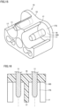
- male connector 10 is based on the ChaoJi standard. As shown in Fig. 2 , male connector 10 includes a pair of male terminals 11, a protective grounding terminal 12, a pair of charging connection confirmation terminals 13, a pair of charging communication terminals 14, and a male casing 15.
- Each male terminal 11 is formed in a round column. Each male terminal 11 is a direct-current power supply terminal. One male terminal 11 is a positive electrode and the other male terminal 11 is a negative electrode. In the present embodiment, male terminal 11 has an outer diameter of 9 mm.
- Protective grounding terminal 12 is disposed at a position spaced from a center portion between the paired male terminals 11 on one side in a direction orthogonal to both an imaginary line connecting the paired male terminals 11 (i.e., a lateral direction in Fig. 2 ) and an axis of each male terminals 11, that is, in a vertical direction in Fig. 2 .
- Each charging connection confirmation terminal 13 is disposed at a position spaced from one male terminal 11 on one side in the orthogonal direction.
- Each charging communication terminal 14 is disposed at a position spaced from the other male terminal 11 on one side in the orthogonal direction and also spaced from each charging connection confirmation terminal 13 in a direction parallel to the imaginary line connecting the paired male terminals 11.
- Male casing 15 holds terminals 11 to 14.
- Male casing 15 is made of resin.
- Male casing 15 has a bottom wall 16 and a tubular wall 17.
- bottom wall 16 holds terminals 11 to 14 in a state in which terminals 11 to 14 are inserted therethrough.
- Bottom wall 16 is formed in a flat plate.
- Fig. 3 shows a part of female connector 20 of charging inlet 2.
- Tubular wall 17 surrounds male terminal 11.
- Tubular wall 17 erects from a portion of bottom wall 16 around male terminal 11.
- Tubular wall 17 has a cylindrical inner peripheral surface.
- Female connector 20 of charging inlet 2 is inserted into a space between the inner peripheral surface and an outer peripheral surface of male terminal 11. As shown in Fig. 3 , tubular wall 17 has an inner diameter set to 23 mm.
- Charging inlet 2 is provided on an external surface of vehicle 1.
- Charging inlet 2 includes female connector 20.
- Female connector 20 has a pair of female terminals 21 and a female casing 25.
- Each female terminal 21 is connectable to male terminal 11. As shown in Fig. 3 , each female terminal 21 has a shape capable of receiving male terminal 11.
- Female casing 25 holds female terminals 21.
- Female casing 25 is made of resin. As shown in Fig. 3 , female casing 25 has a facing portion 26 and a tubular portion 27.
- Facing portion 26 is a portion facing tubular wall 17 in a direction parallel to the axial direction of male terminal 11 (i.e., a vertical direction in Fig. 3 ). Facing portion 26 has a surface 26S formed flat. As shown in Fig. 3 , a distance between surface 26S of facing portion 26 and a surface 16S of bottom wall 16 in the direction parallel to the axial direction of male terminal 11 is set to 40 mm.
- Tubular portion 27 is formed to have a cylindrical shape surrounding female terminal 21.
- Tubular portion 27 is connected to facing portion 26 in a posture such that tubular portion 27 has its center axis orthogonal to facing portion 26.
- Tubular portion 27 has an outer diameter smaller than the inner diameter of tubular wall 17.
- distal end portion 27a has a length set to 6 mm in a direction parallel to the axial direction of tubular portion 27.
- Evaluation jig 50 is a jig capable of evaluating charging connector 5 in coolability (or amount of heat generated at a connecting portion of male terminal 11 and the female terminal). As shown in Fig. 4 , evaluation jig 50 includes a pair of female terminals 100, an electric wire 200, a pair of crimp terminals 300, and a pair of adjustment members 400.
- Each female terminal 100 is a terminal connected to male terminal 11.
- Each female terminal 100 includes a plurality of (eight in the present embodiment) contact pieces 110, a support portion 120, and a female-side flange 130.
- Each contact piece 110 is a portion that can contact male terminal 11.
- the plurality of contact pieces 110 are disposed about and spaced from a center axis A (see Figs. 11 to 13 ). Specifically, the plurality of contact pieces 110 are disposed about and equally spaced from center axis A.
- Contact pieces 110 are preferably set in number to 3 or more and 8 or less, particularly preferably 8.
- Each contact piece 110 has a flexible piece 112 and a contact portion 114.
- Flexible piece 112 has a shape extending in a direction parallel to center axis A. Flexible piece 112 forms a portion of a cylinder having center axis A. In other words, in the cross sections shown in Figs. 12 and 13 , flexible piece 112 has an outer peripheral surface in the form of an arc. A slit 112S is provided between any pair of flexible pieces 112 adjacent in the circumferential direction of the cylinder.
- flexible piece 112 has a length L1 (see Fig. 7 ) set to be equal to or larger than twice the outer diameter of the cylinder.
- the cylinder has an outer diameter ⁇ 2 (see Fig. 11 ) of 17 mm, and flexible piece 112 has length L1 of 35 mm.
- the cylinder has an inner diameter ⁇ 1 (see Fig. 11 ) of 13 mm. That is, flexible piece 112 has a thickness of 2 mm.
- Flexible piece 112 is elastically deformable such that flexible piece 112 has a distal end portion 112a displaced in the radial direction of the cylinder relative to a proximal end portion of flexible piece 112, which is a connecting portion of flexible piece 112 and support portion 120. That is, the plurality of contact pieces 110 (the cylinder) can be reduced in diameter.
- flexible piece 112 has a facing surface 112b facing flexible piece 112 adjacent to flexible piece 112 of interest in the circumferential direction of the cylinder. Any pair of facing surfaces 112b facing each other in the circumferential direction are parallel to each other. The paired facing surfaces 112b are spaced by 1 mm.
- Contact portion 114 has a shape protruding from the inner surface of flexible piece 112 toward center axis A. Contact portion 114 is connected to the inner surface of flexible piece 112 at a portion away from distal end portion 112a in the direction parallel to center axis A. That is, distal end portion 112a of flexible piece 112 configures a protruding portion protruding from contact portion 114 in the direction parallel to center axis A away from support portion 120 (or downward in Fig. 11 ).
- Contact portion 114 has a shape curved so as to protrude inward in the radial direction. As shown in Fig. 13 , flexible piece 112 and contact portion 114 have a boundary portion 113 therebetween in a curve. Contact portion 114 has an apex 114c with a curvature smaller than that of boundary portion 113. In the present embodiment, apex 114c has a radius of curvature of 1 mm. Boundary portion 113 has a radius of curvature for example of 0.5 mm.
- a straight line connecting a specific apex 114c and center axis A and a straight line connecting an apex 114c adjacent to the specific apex 114c and center axis A form an angle of 45 degrees.
- a tangent to an end on one side of contact portion 114 in the circumferential direction and a tangent to an end on the other side of contact portion 114 in the circumferential direction form an angle of 30 degrees.
- Contact portion 114 has a shape extending in the direction parallel to center axis A. As shown in Figs. 10 and 11 , contact portion 114 has a contact edge portion 114a and a connecting portion 114b.
- Contact portion 114 has a shape extending in the direction parallel to center axis A. Contact edge portion 114a has a length L3 of 4.7 mm.
- Connecting portion 114b connects contact edge portion 114a and an inner surface of flexible piece 112.
- Connecting portion 114b has a shape inclined so as to gradually approach the inner surface of flexible piece 112 as connecting portion 114b is farther away from contact edge portion 114a in the direction parallel to center axis A.
- Connecting portion 114b and the inner surface of flexible piece 112 have a boundary portion therebetween with a radius of curvature of 0.5 mm.
- Connecting portion 114b and contact edge portion 114a have a boundary portion therebetween with a radius of curvature of 1.5 mm.
- Support portion 120 supports the plurality of contact pieces 110.
- support portion 120 is formed to have a cylindrical shape having center axis A as a center.
- Support portion 120 has an outer peripheral surface contiguous to that of each flexible piece 112. That is, support portion 120 has an outer diameter equal to that of the cylinder composed of the plurality of flexible pieces 112.
- support portion 120 is equal in thickness to each flexible piece 112. As shown in Fig. 7 , in a direction along center axis A, support portion 120 has a length L2 set to be smaller than length L1 of each flexible piece 112. Specifically, support portion 120 has length L2 of 22 mm. Support portion 120 may be formed in a round columnar shape, a rectangular columnar shape, or the like.
- Female-side flange 130 has a shape projecting from an outer peripheral surface of support portion 120 outward in the radial direction of support portion 120.
- Female-side flange 130 is formed flat. In the direction parallel to center axis A, female-side flange 130 has a length equal to that of support portion 120 (22 mm in the present embodiment).
- Female-side flange 130 is provided with an insertion hole 130h.
- Insertion hole 130h has a diameter of 10.5 mm.
- a distance between center axis A and the center of insertion hole 130h is 21 mm.
- Electric wire 200 is provided to connect the paired female terminals 100 to each other.
- Electric wire 200 is made of copper or silver.
- Electric wire 200 preferably has a cross-sectional area set to 70 mm 2 or more and 95 mm 2 or less. In the present embodiment, electric wire 200 has a cross-sectional area set to 95 mm 2 .
- Electric wire 200 has a length set to 2 m or more. The reason for this will be described with reference to Fig. 19 .
- Fig. 19 represents each terminal and each electric wire in temperature when male terminal 11 is connected to female terminal 21 and a current of 400 A is supplied for 30 minutes.
- a region R of a connecting portion of male terminal 11 and female terminal 21 is a region which attains highest temperature.
- a vehicle-side electric wire 3 has a cross-sectional area of 95 mm 2 , and whether a portion up to 100 cm from male terminal 11 may or may not be cooled with water, it has been confirmed that a portion of vehicle-side electric wire 3 away from female terminal 21 by 100 cm is stable in temperature (or an effect of heat generated at the connecting portion of male terminal 11 and female terminal 21 is substantially negligible).
- vehicle-side electric wire 3 may have a cross-sectional area of 70 mm 2 or 95 mm 2 , it has been confirmed that the portion of vehicle-side electric wire 3 away from female terminal 21 by 100 cm is stable in temperature (or an effect of heat generated at the connecting portion of male terminal 11 and female terminal 21 is substantially negligible).
- electric wire 200 is set to have a length of 2 m or more.
- Each crimp terminal 300 is connected to an end 210 of electric wire 200.
- Each crimp terminal 300 has a crimp portion 310 and a crimp-side flange 320.
- Crimp portion 310 crimps end 210 of electric wire 200.
- Crimp-side flange 320 is connected to crimp portion 310.
- Crimp-side flange 320 is formed flat.
- Crimp-side flange 320 is provided with an insertion hole (not shown).
- Crimp-side flange 320 is fixed to female-side flange 130 by a bolt B and a nut (not shown).
- Bolt B is inserted into insertion hole 130h of female-side flange 130 and the insertion hole of crimp-side flange 320.
- Adjustment member 400 can adjust contact resistance of female terminal 100 and male terminal 11. Specifically, adjustment member 400 can apply an external force to each female terminal 100 to reduce each female terminal 100 in diameter. Adjustment member 400 includes an annular band 410, a metal band 420, and an adjustment unit 430.
- Annular band 410 is attached around the plurality of contact pieces 110. Annular band 410 surrounds the entire circumference of the plurality of contact pieces 110. Annular band 410 is made of an electrically and thermally insulating material (resin or the like). In the direction parallel to center axis A, annular band 410 is smaller in length than slit 112S.
- Metal band 420 is wrapped around annular band 410. Metal band 420 can apply an external force to the plurality of contact pieces 110 of female terminal 100 to reduce the plurality of contact pieces 110 in diameter.
- Adjustment unit 430 can adjust a force applied by metal band 420 to clamp the plurality of contact pieces 110 (or reduce the plurality of contact pieces 110 in diameter). Specifically, adjustment unit 430 adjusts metal band 420 in diameter to adjust the clamping force. Adjustment unit 430 has a screw capable of adjusting metal band 420 in diameter.
- charging connector 5 is evaluated in coolability by connecting the pair of female terminals 100 of evaluation jig 50 to the pair of male terminals 11 of male connector 10.
- This evaluation method includes a removing step, a connecting step, an adjusting step, and an evaluating step.
- the removing step is a step of removing a portion of each tubular wall 17 of male casing 15. Specifically, as shown in Figs. 14 to 16 , in the removing step, each tubular wall 17 is partially removed to form around male terminal 11 an operating space 17S allowing an operation to be performed therein via adjustment unit 430 to adjust the external force. This partially exposes each male terminal 11.
- the removing step removes a portion other than a portion capable of suppressing a short circuit of male terminals 11 or male terminal 11 and other terminals 12 to 14, that is, a portion of tubular wall 17 where paired tubular walls 17 face each other.
- a portion of tubular wall 17 outside male terminal 11 in a direction of an imaginary line connecting male terminal 11 and protective grounding terminal 12 is removed.
- the connecting step is a step of connecting the pair of female terminals 100 of evaluation jig 50 to the pair of male terminals 11.
- female terminal 100 is connected to male terminal 11.
- female terminal 100 is inserted until distal end portion 112a of each flexible piece 112 contacts surface 16S of bottom wall 16 of male casing 15.
- Fig. 17 shows one female terminal 100 alone receiving male terminal 11.
- the adjusting step is a step of adjusting a connection state of male terminal 11 and female terminal 100.
- the external force (the clamping force by metal band 420) is adjusted by adjustment unit 430.
- the external force is adjusted by operating adjustment unit 430 with an operating tool (not shown) in operating space 17S so that contact resistance between male terminal 11 and female terminal 100 falls within a prescribed range.
- the clamping force of adjustment unit 430 is adjusted with the operating tool.
- the external force is preferably adjusted so that the contact resistance is 0.06 m ⁇ or more and 0.15 m ⁇ or less, more preferably 0.08 m ⁇ or more and 0.1 m ⁇ or less.
- the contact resistance is measured by a resistance value between a point P1 of 4.5 mm from surface 16S of bottom wall 16 and a point P2 of 43 mm from surface 16S of bottom wall 16.
- the contact resistance may be measured with a milliohm tester or may be determined by a voltage drop caused when a current of 400 A is supplied.
- Point P2 is in a vicinity of a boundary between a region affected by a standard applied in designing male connector 10 including male terminal 11 and a region unaffected thereby.
- a charging current of 400 A is supplied for 30 minutes, and the charging connector is evaluated in coolability by whether male terminal 11 and female terminal 100 have a temperature of 90°C or lower. Whether male terminal 11 and female terminal 100 have such a temperature may be detected with a temperature sensor (not shown) provided to male terminal 11 or female terminal 100.
- evaluation jig 50 of the present embodiment an amount of heat generated when charging connector 5 has a current passing therethrough can appropriately be evaluated.
- An evaluation jig of the above embodiment comprises a pair of female terminals connectable to a pair of male terminals of a charging connector, and an electric wire connecting the paired female terminals, the electric wire having a cross-sectional area of 70 mm 2 or more and 95 mm 2 or less and a length of 2 m or more.
- the evaluation jig that comprises the electric wire having a cross-sectional area of 70 mm 2 or more and 95 mm 2 or less and a length of 2 m or more allows an appropriate evaluation of an amount of heat generated (or a degree at which temperature rise) at a connecting portion of a male terminal and a female terminal without being substantially affected by the electric wire's heat radiation characteristic when a current passes (or the evaluation is made).
- Each terminal can thus be designed based on a result of the evaluation.
- the electric wire is made of copper.
- an evaluation jig comprises a pair of female terminals connectable to a pair of male terminals of a charging connector, and an adjustment member that can adjust contact resistance of the female terminal and the male terminal, wherein the female terminal can be reduced in diameter
- the adjustment member includes an annular band attached to an outer peripheral surface of the female terminal and formed in an annular shape surrounding the female terminal, a metal band attached to an outer peripheral surface of the annular band and capable of applying an external force to the female terminal to reduce the female terminal in diameter, and an adjustment unit that can adjust the external force applied by the metal band to the female terminal, and the annular band is made of an electrically and thermally insulating material.
- the evaluation jig that comprises the adjustment unit that can adjust the external (or clamping) force applied by the metal band to the female terminal can adjust contact resistance between the male terminal and the female terminal, and furthermore, the annular band disposed between the female terminal and the metal band that is made of an electrically and thermally insulating material can suppress heat radiation caused at the metal band or the adjustment unit, and hence reduction in accuracy in evaluating an amount of heat generated at a connecting portion of the male terminal and the female terminal.
- An evaluation method of the above embodiment is an evaluation method performed by connecting to a charging connector including a pair of male terminals that can be cooled with a coolant an evaluation jig including a pair of female terminals connectable to the pair of male terminals, by connecting the pair of female terminals of the evaluation jig to the pair of male terminals of the charging connector, for evaluating the charging connector in coolability, the method comprising: connecting the pair of female terminals to the pair of male terminals; adjusting a connection state of the male terminal and the female terminal so that a contact resistance between the male terminal and the female terminal is 0.06 m ⁇ or more and 0.15 m ⁇ or less; and, after the step of adjusting, evaluating the coolability depending on whether the male terminal and the female terminal have a temperature of 90°C or lower when a charging current of 400 A is supplied to the male terminal and the female terminal for 30 minutes.
- contact resistance between the male terminal and the female terminal is defined to fall within a range of 0.06 m ⁇ or more and 0.15 m ⁇ or less, and variation in evaluation results is suppressed. Therefore, the charging connector's coolability can be appropriately evaluated. Further, designing the female terminal of the charging inlet such that the contact resistance is 0.06 m ⁇ or more and 0.15 m ⁇ or less allows the male terminal and the female terminal to have a temperature of 90°C or lower when a charging connector which obtains a good evaluation result in the step of evaluating is used to charge power with a charging current of 400 A supplied for 30 minutes.
- the connection state is adjusted so that the contact resistance is 0.08 m ⁇ or more and 0.1 m ⁇ or less.
- an evaluation method of the above embodiment is an evaluation method performed by connecting to a charging connector including a pair of male terminals that can be cooled with a coolant and a bottom wall that holds the pair of male terminals in a state in which the pair of male terminals are inserted therethrough an evaluation jig including a pair of female terminals connectable to the pair of male terminals, by connecting the pair of female terminals of the evaluation jig to the pair of male terminals of the charging connector, for evaluating the charging connector in coolability, the method comprising: connecting the pair of female terminals to the pair of male terminals; and adjusting a connection state of the male terminal and the female terminal so that contact resistance between the male terminal and the female terminal falls within a prescribed range, wherein in the step of adjusting, a resistance between a point of 4.5 mm of the male terminal from a surface of the bottom wall and a point of 43 mm of the female terminal from the surface of the bottom wall is measured as the contact resistance.
- a measurement point for contact resistance between the male terminal and the female terminal is determined, and an appropriate evaluation result of the coolability can be obtained.
- a measurement point on the side of the male terminal is a point of 4.5 mm from the surface of the bottom wall. At this point, the male terminal has a sufficiently large cross-sectional area, and an effect on the contact resistance is reduced.
- a measurement point on the side of the female terminal is a point of 43 mm from the surface of the bottom wall. This point is in a vicinity of a boundary of a region affected by a standard applied in designing the charging connector including the male terminal and a region unaffected by the standard. Therefore, designing the female terminal of the charging inlet to achieve contact resistance equal to or less than that measured at this point suppresses the male and female terminals' temperature to be a reference value or smaller when a charging connector that satisfies the standard is used to charge power.
- the evaluation method further comprises, after the step of adjusting, evaluating the coolability based on whether the male terminal and the female terminal have a temperature equal to or lower than 90°C when a charging current of 400 A is supplied to the male terminal and the female terminal for 30 minutes.
- an evaluation jig of the above embodiment includes a pair of female terminals connectable to a pair of male terminals of a charging connector, and an adjustment member that can adjust contact resistance of the female terminal and the male terminal, wherein the female terminal can be reduced in diameter, and the adjustment member can apply an external force to the female terminal to reduce the female terminal in diameter.
- the female terminal can be reduced in diameter and the adjustment member can apply an external force to the female terminal to reduce the female terminal in diameter, and contact resistance of the male terminal and the female terminal can be adjusted to fall within a prescribed range.
- the charging connector's coolability can be appropriately evaluated.
- an evaluation method of the above embodiment is a method performed by connecting to a charging connector including a pair of male terminals that can be cooled with a coolant and a pair of tubular walls surrounding each of the paired male terminals an evaluation jig including a pair of female terminals that can be connected to the pair of male terminals and reduced in diameter and an adjustment member that can apply an external force to each of the paired female terminals to reduce the female terminal in diameter, by connecting the pair of female terminals of the evaluation jig to the pair of male terminals of the charging connector, for evaluating the charging connector in coolability, the method comprising: partially removing each tubular wall of the paired tubular walls to form around the male terminal an operating space allowing an operation to be performed therein via the adjustment member to adjust the external force; connecting the pair of female terminals to the pair of male terminals; and adjusting the external force in the operating space by the adjustment member so that contact resistance between the male terminal and the female terminal falls within a prescribed range.
- an operating space allowing an operation to be performed therein to adjust external force is formed around a male terminal, and contact resistance can be adjusted in a state with the evaluation jig having a female terminal connected to the male terminal.
- the tubular wall preferably has removed a portion other than a portion at which the paired tubular walls face each other.
- the adjustment member may include an annular band that is attached to an outer peripheral surface of the female terminal and formed in an annular shape surrounding the female terminal, a metal band that is attached to an outer peripheral surface of the annular band and can apply a force to the female terminal to reduce the female terminal in diameter, and an adjustment unit that can adjust a force applied by the metal band to clamp the female terminal, and the annular band may be made of an electrically and thermally insulating material.
- the pair of female terminals is connected to the pair of male terminals in a state with the annular and metal bands attached to each female terminal, and in the step of adjusting, the force applied by the metal band to clamp the female terminal is adjusted in the operating space.
- an evaluation jig of the above embodiment comprises a female terminal connectable to a male terminal of a charging connector, the female terminal including a plurality of contact pieces which can each contact the male terminal and are spaced about a center axis, and a support portion to support the plurality of contact pieces, the plurality of contact pieces each having a flexible piece having a shape extending from the support portion in a direction parallel to the center axis, and a contact portion protruding toward the center axis from an inner surface of the flexible piece, the flexible piece forming a portion of a cylinder having the center axis, the flexible piece having a length equal to or larger than twice an outer diameter of the cylinder in a direction parallel to the center axis, the flexible piece being elastically deformable so that the flexible piece has a distal end portion to be displaceable in a radial direction of the cylinder relative to a proximal end portion of the flexible piece serving as a connecting portion of the flexible piece and the support portion, the contact portion having a
- the flexible piece that has a length equal to or greater than twice the outer diameter of the cylinder in the direction parallel to the center axis is each less plastically deformable when the female terminal is repeatedly connected to and pulled out of the male terminal, and furthermore, each contact portion having a shape curved so as to protrude inward in the radial direction reliably contacts the male terminal. This allows prescribed contact resistance to be reliably reproduced and the charging connector's coolability to be evaluated appropriately.
- the contact portion has a shape extending in a direction parallel to the center axis.
- the female terminal is guided to have a posture so that the center axes match each other.
- the flexible piece has a protruding portion protruding from the contact portion in a direction parallel to the center axis away from the support portion.
- the flexible piece and the contact portion have a boundary portion therebetween in a curved shape.
- the contact portion preferably has an apex smaller in curvature than the boundary portion.
- the flexible piece has a facing surface facing a flexible piece adjacent to the flexible piece of interest in the circumferential direction of the cylinder, and any pair of such facing surfaces facing each other in the circumferential direction are parallel to each other.
Landscapes
- Engineering & Computer Science (AREA)
- Business, Economics & Management (AREA)
- Human Resources & Organizations (AREA)
- Mechanical Engineering (AREA)
- Transportation (AREA)
- Power Engineering (AREA)
- General Physics & Mathematics (AREA)
- Physics & Mathematics (AREA)
- Economics (AREA)
- Strategic Management (AREA)
- Entrepreneurship & Innovation (AREA)
- Marketing (AREA)
- Health & Medical Sciences (AREA)
- Tourism & Hospitality (AREA)
- General Business, Economics & Management (AREA)
- Theoretical Computer Science (AREA)
- Development Economics (AREA)
- Educational Administration (AREA)
- Game Theory and Decision Science (AREA)
- General Health & Medical Sciences (AREA)
- Operations Research (AREA)
- Quality & Reliability (AREA)
- Public Health (AREA)
- Water Supply & Treatment (AREA)
- Primary Health Care (AREA)
- Chemical & Material Sciences (AREA)
- Combustion & Propulsion (AREA)
- Electric Propulsion And Braking For Vehicles (AREA)
- Manufacturing Of Electrical Connectors (AREA)
- Connector Housings Or Holding Contact Members (AREA)
- Charge And Discharge Circuits For Batteries Or The Like (AREA)
Applications Claiming Priority (1)
| Application Number | Priority Date | Filing Date | Title |
|---|---|---|---|
| JP2020003137A JP6958642B2 (ja) | 2020-01-10 | 2020-01-10 | 評価治具 |
Publications (2)
| Publication Number | Publication Date |
|---|---|
| EP3848230A1 EP3848230A1 (en) | 2021-07-14 |
| EP3848230B1 true EP3848230B1 (en) | 2023-10-11 |
Family
ID=74095761
Family Applications (1)
| Application Number | Title | Priority Date | Filing Date |
|---|---|---|---|
| EP21150113.5A Active EP3848230B1 (en) | 2020-01-10 | 2021-01-04 | Evaluation jig |
Country Status (4)
| Country | Link |
|---|---|
| US (2) | US11345247B2 (ja) |
| EP (1) | EP3848230B1 (ja) |
| JP (2) | JP6958642B2 (ja) |
| CN (1) | CN113191578A (ja) |
Families Citing this family (5)
| Publication number | Priority date | Publication date | Assignee | Title |
|---|---|---|---|---|
| JP6933270B2 (ja) * | 2020-01-10 | 2021-09-08 | トヨタ自動車株式会社 | 評価治具 |
| JP7088216B2 (ja) * | 2020-01-10 | 2022-06-21 | トヨタ自動車株式会社 | レファレンス治具 |
| JP6958642B2 (ja) * | 2020-01-10 | 2021-11-02 | トヨタ自動車株式会社 | 評価治具 |
| JP6958644B2 (ja) | 2020-01-10 | 2021-11-02 | トヨタ自動車株式会社 | 評価治具及び評価方法 |
| JP7464572B2 (ja) * | 2021-09-22 | 2024-04-09 | 矢崎総業株式会社 | 充電コネクタ |
Family Cites Families (39)
| Publication number | Priority date | Publication date | Assignee | Title |
|---|---|---|---|---|
| US3951505A (en) * | 1975-05-01 | 1976-04-20 | Williams Robert A | Strain relief system for electrical connectors |
| US3985411A (en) * | 1975-06-30 | 1976-10-12 | I-T-E Imperial Corporation | Hinged ground clamp |
| US4207611A (en) * | 1978-12-18 | 1980-06-10 | Ford Motor Company | Apparatus and method for calibrated testing of a vehicle electrical system |
| ES277003Y (es) * | 1984-01-20 | 1985-02-01 | Canturri Muntanya Juan | Acondicionador termico reversible de uso domestico individual para liquidos |
| US5616036A (en) * | 1995-10-27 | 1997-04-01 | Thomas Polidori | Grounding clamp |
| JP2900877B2 (ja) * | 1996-03-22 | 1999-06-02 | 日本電気株式会社 | 半導体デバイスの配線電流観測方法、配線系欠陥検査方法およびその装置 |
| US6089880A (en) | 1996-11-28 | 2000-07-18 | Denso Corporation | Electric connector arrangement |
| JP2003269423A (ja) * | 2002-03-18 | 2003-09-25 | Nifco Inc | 板の連結用ファスナー |
| EP1623485B1 (en) * | 2003-05-02 | 2014-03-12 | Anderson Power Products | A biased socket contact and a method thereof |
| US7457980B2 (en) * | 2004-08-13 | 2008-11-25 | Ken Qing Yang | Data replication method over a limited bandwidth network by mirroring parities |
| US7429199B2 (en) | 2005-08-12 | 2008-09-30 | Burgess James P | Low resistance, low insertion force electrical connector |
| US7658641B1 (en) * | 2006-09-08 | 2010-02-09 | Mechanical Answers Llc | Compressive collet electrical clamp and contact and method |
| JP5053759B2 (ja) | 2006-10-18 | 2012-10-17 | 株式会社オートネットワーク技術研究所 | ソケット端子 |
| JP4971075B2 (ja) | 2007-08-24 | 2012-07-11 | 株式会社オートネットワーク技術研究所 | ソケット端子 |
| JP5178699B2 (ja) | 2009-12-18 | 2013-04-10 | 中国電力株式会社 | 検査治具及びその製造方法 |
| US9287646B2 (en) | 2010-10-14 | 2016-03-15 | Gregory thomas mark | Actively cooled electrical connection |
| CN102810790B (zh) * | 2011-05-30 | 2015-07-22 | 比亚迪股份有限公司 | 车用连接器 |
| JP6100495B2 (ja) | 2012-10-02 | 2017-03-22 | 矢崎総業株式会社 | メス端子 |
| JP2014154377A (ja) * | 2013-02-08 | 2014-08-25 | Auto Network Gijutsu Kenkyusho:Kk | 充電コネクタ |
| JP6146668B2 (ja) * | 2013-09-27 | 2017-06-14 | 株式会社オートネットワーク技術研究所 | 端子金具 |
| JP6238359B2 (ja) * | 2014-04-23 | 2017-11-29 | 日本航空電子工業株式会社 | ソケットコンタクト |
| JP2016094963A (ja) * | 2014-11-12 | 2016-05-26 | トヨタ自動車株式会社 | 配管用継手構造 |
| WO2017019567A1 (en) * | 2015-07-24 | 2017-02-02 | Pct International, Inc. | Coaxial cable connector with continuity member |
| FR3048136B1 (fr) * | 2016-02-18 | 2021-05-14 | Ilie Razvan | Connecteur electrique comportant une pluralite de lamelles electriquement conductrices |
| DE102016105311A1 (de) | 2016-03-22 | 2017-09-28 | Phoenix Contact E-Mobility Gmbh | Steckverbinderteil mit einem gekühlten Kontaktelement |
| DE202016106663U1 (de) | 2016-11-30 | 2018-03-01 | Phoenix Contact E-Mobility Gmbh | Elektrisches Kontaktelement zum elektrischen Kontaktieren mit einem Gegenkontaktelement |
| WO2019162532A1 (en) | 2018-02-26 | 2019-08-29 | Stiftung Tierärztliche Hochschule Hannover (Tiho) | Improved pneumovirus reverse genetics |
| WO2019171914A1 (ja) * | 2018-03-08 | 2019-09-12 | 株式会社オートネットワーク技術研究所 | 雌端子 |
| JP7012940B2 (ja) | 2018-03-08 | 2022-01-31 | 株式会社オートネットワーク技術研究所 | 雌端子 |
| DE102018105507A1 (de) | 2018-03-09 | 2019-09-12 | Phoenix Contact E-Mobility Gmbh | Vorrichtung zum Prüfen einer Kontaktkraft einer elektromechanischen Verbindung und Ladevorrichtung für ein Elektrofahrzeug |
| JP7035738B2 (ja) | 2018-04-06 | 2022-03-15 | トヨタ自動車株式会社 | 車両および車両の充電方法 |
| JP2019197641A (ja) | 2018-05-09 | 2019-11-14 | トヨタ自動車株式会社 | コネクタ |
| JP6820292B2 (ja) * | 2018-06-19 | 2021-01-27 | 矢崎総業株式会社 | 導通部材 |
| JP6820291B2 (ja) * | 2018-06-19 | 2021-01-27 | 矢崎総業株式会社 | コネクタ装置 |
| JP7144215B2 (ja) | 2018-06-28 | 2022-09-29 | 株式会社Nttファシリティーズ | 設備制御システム |
| CN109038018B (zh) * | 2018-09-20 | 2024-05-07 | 旭立辰新能源(东莞)有限公司 | 一种线簧端子连接结构 |
| JP6981388B2 (ja) | 2018-10-04 | 2021-12-15 | 株式会社オートネットワーク技術研究所 | 雄型コネクタおよびコネクタ装置 |
| JP6958644B2 (ja) | 2020-01-10 | 2021-11-02 | トヨタ自動車株式会社 | 評価治具及び評価方法 |
| JP6958642B2 (ja) * | 2020-01-10 | 2021-11-02 | トヨタ自動車株式会社 | 評価治具 |
-
2020
- 2020-01-10 JP JP2020003137A patent/JP6958642B2/ja active Active
- 2020-12-09 US US17/116,001 patent/US11345247B2/en active Active
-
2021
- 2021-01-04 EP EP21150113.5A patent/EP3848230B1/en active Active
- 2021-01-08 CN CN202110024741.3A patent/CN113191578A/zh active Pending
- 2021-08-19 JP JP2021133994A patent/JP7355080B2/ja active Active
-
2022
- 2022-03-21 US US17/699,504 patent/US11673481B2/en active Active
Also Published As
| Publication number | Publication date |
|---|---|
| JP7355080B2 (ja) | 2023-10-03 |
| JP2021185575A (ja) | 2021-12-09 |
| US20210213841A1 (en) | 2021-07-15 |
| EP3848230A1 (en) | 2021-07-14 |
| JP2021112050A (ja) | 2021-08-02 |
| CN113191578A (zh) | 2021-07-30 |
| US11345247B2 (en) | 2022-05-31 |
| JP6958642B2 (ja) | 2021-11-02 |
| US20220212552A1 (en) | 2022-07-07 |
| US11673481B2 (en) | 2023-06-13 |
Similar Documents
| Publication | Publication Date | Title |
|---|---|---|
| EP3848230B1 (en) | Evaluation jig | |
| EP3848231B1 (en) | Evaluation method | |
| EP3848232B1 (en) | Evaluation jig and evaluation method | |
| US20230291214A1 (en) | Reference jig | |
| US20230302944A1 (en) | Jig for connector current evaluation | |
| EP3848236A1 (en) | Evaluation method | |
| JP7099651B2 (ja) | 評価方法 | |
| JP2022132309A (ja) | 評価方法 |
Legal Events
| Date | Code | Title | Description |
|---|---|---|---|
| PUAI | Public reference made under article 153(3) epc to a published international application that has entered the european phase |
Free format text: ORIGINAL CODE: 0009012 |
|
| STAA | Information on the status of an ep patent application or granted ep patent |
Free format text: STATUS: REQUEST FOR EXAMINATION WAS MADE |
|
| 17P | Request for examination filed |
Effective date: 20210104 |
|
| AK | Designated contracting states |
Kind code of ref document: A1 Designated state(s): AL AT BE BG CH CY CZ DE DK EE ES FI FR GB GR HR HU IE IS IT LI LT LU LV MC MK MT NL NO PL PT RO RS SE SI SK SM TR |
|
| RIC1 | Information provided on ipc code assigned before grant |
Ipc: H01R 13/193 20060101ALI20230331BHEP Ipc: G01R 31/00 20060101ALI20230331BHEP Ipc: G01R 27/20 20060101ALI20230331BHEP Ipc: B60L 53/302 20190101ALI20230331BHEP Ipc: B60L 53/16 20190101ALI20230331BHEP Ipc: B60L 53/10 20190101AFI20230331BHEP |
|
| GRAP | Despatch of communication of intention to grant a patent |
Free format text: ORIGINAL CODE: EPIDOSNIGR1 |
|
| STAA | Information on the status of an ep patent application or granted ep patent |
Free format text: STATUS: GRANT OF PATENT IS INTENDED |
|
| INTG | Intention to grant announced |
Effective date: 20230515 |
|
| GRAS | Grant fee paid |
Free format text: ORIGINAL CODE: EPIDOSNIGR3 |
|
| GRAA | (expected) grant |
Free format text: ORIGINAL CODE: 0009210 |
|
| STAA | Information on the status of an ep patent application or granted ep patent |
Free format text: STATUS: THE PATENT HAS BEEN GRANTED |
|
| AK | Designated contracting states |
Kind code of ref document: B1 Designated state(s): AL AT BE BG CH CY CZ DE DK EE ES FI FR GB GR HR HU IE IS IT LI LT LU LV MC MK MT NL NO PL PT RO RS SE SI SK SM TR |
|
| REG | Reference to a national code |
Ref country code: GB Ref legal event code: FG4D |
|
| REG | Reference to a national code |
Ref country code: CH Ref legal event code: EP |
|
| REG | Reference to a national code |
Ref country code: DE Ref legal event code: R096 Ref document number: 602021005686 Country of ref document: DE |
|
| REG | Reference to a national code |
Ref country code: IE Ref legal event code: FG4D |
|
| P01 | Opt-out of the competence of the unified patent court (upc) registered |
Effective date: 20231024 |
|
| PGFP | Annual fee paid to national office [announced via postgrant information from national office to epo] |
Ref country code: FR Payment date: 20231212 Year of fee payment: 4 |
|
| REG | Reference to a national code |
Ref country code: LT Ref legal event code: MG9D |
|
| REG | Reference to a national code |
Ref country code: NL Ref legal event code: MP Effective date: 20231011 |
|
| REG | Reference to a national code |
Ref country code: AT Ref legal event code: MK05 Ref document number: 1619896 Country of ref document: AT Kind code of ref document: T Effective date: 20231011 |
|
| PG25 | Lapsed in a contracting state [announced via postgrant information from national office to epo] |
Ref country code: NL Free format text: LAPSE BECAUSE OF FAILURE TO SUBMIT A TRANSLATION OF THE DESCRIPTION OR TO PAY THE FEE WITHIN THE PRESCRIBED TIME-LIMIT Effective date: 20231011 |
|
| PG25 | Lapsed in a contracting state [announced via postgrant information from national office to epo] |
Ref country code: GR Free format text: LAPSE BECAUSE OF FAILURE TO SUBMIT A TRANSLATION OF THE DESCRIPTION OR TO PAY THE FEE WITHIN THE PRESCRIBED TIME-LIMIT Effective date: 20240112 |
|
| PG25 | Lapsed in a contracting state [announced via postgrant information from national office to epo] |
Ref country code: IS Free format text: LAPSE BECAUSE OF FAILURE TO SUBMIT A TRANSLATION OF THE DESCRIPTION OR TO PAY THE FEE WITHIN THE PRESCRIBED TIME-LIMIT Effective date: 20240211 |
|
| PG25 | Lapsed in a contracting state [announced via postgrant information from national office to epo] |
Ref country code: LT Free format text: LAPSE BECAUSE OF FAILURE TO SUBMIT A TRANSLATION OF THE DESCRIPTION OR TO PAY THE FEE WITHIN THE PRESCRIBED TIME-LIMIT Effective date: 20231011 |
|
| REG | Reference to a national code |
Ref country code: DE Ref legal event code: R084 Ref document number: 602021005686 Country of ref document: DE |
|
| PG25 | Lapsed in a contracting state [announced via postgrant information from national office to epo] |
Ref country code: AT Free format text: LAPSE BECAUSE OF FAILURE TO SUBMIT A TRANSLATION OF THE DESCRIPTION OR TO PAY THE FEE WITHIN THE PRESCRIBED TIME-LIMIT Effective date: 20231011 |
|
| PG25 | Lapsed in a contracting state [announced via postgrant information from national office to epo] |
Ref country code: ES Free format text: LAPSE BECAUSE OF FAILURE TO SUBMIT A TRANSLATION OF THE DESCRIPTION OR TO PAY THE FEE WITHIN THE PRESCRIBED TIME-LIMIT Effective date: 20231011 |
|
| PG25 | Lapsed in a contracting state [announced via postgrant information from national office to epo] |
Ref country code: LT Free format text: LAPSE BECAUSE OF FAILURE TO SUBMIT A TRANSLATION OF THE DESCRIPTION OR TO PAY THE FEE WITHIN THE PRESCRIBED TIME-LIMIT Effective date: 20231011 Ref country code: IS Free format text: LAPSE BECAUSE OF FAILURE TO SUBMIT A TRANSLATION OF THE DESCRIPTION OR TO PAY THE FEE WITHIN THE PRESCRIBED TIME-LIMIT Effective date: 20240211 Ref country code: GR Free format text: LAPSE BECAUSE OF FAILURE TO SUBMIT A TRANSLATION OF THE DESCRIPTION OR TO PAY THE FEE WITHIN THE PRESCRIBED TIME-LIMIT Effective date: 20240112 Ref country code: ES Free format text: LAPSE BECAUSE OF FAILURE TO SUBMIT A TRANSLATION OF THE DESCRIPTION OR TO PAY THE FEE WITHIN THE PRESCRIBED TIME-LIMIT Effective date: 20231011 Ref country code: BG Free format text: LAPSE BECAUSE OF FAILURE TO SUBMIT A TRANSLATION OF THE DESCRIPTION OR TO PAY THE FEE WITHIN THE PRESCRIBED TIME-LIMIT Effective date: 20240111 Ref country code: AT Free format text: LAPSE BECAUSE OF FAILURE TO SUBMIT A TRANSLATION OF THE DESCRIPTION OR TO PAY THE FEE WITHIN THE PRESCRIBED TIME-LIMIT Effective date: 20231011 Ref country code: PT Free format text: LAPSE BECAUSE OF FAILURE TO SUBMIT A TRANSLATION OF THE DESCRIPTION OR TO PAY THE FEE WITHIN THE PRESCRIBED TIME-LIMIT Effective date: 20240212 |
|
| PGFP | Annual fee paid to national office [announced via postgrant information from national office to epo] |
Ref country code: DE Payment date: 20231212 Year of fee payment: 4 |