EP3845945B1 - Signalverarbeitungsvorrichtung, signalverarbeitungsverfahren, signalverarbeitungsprogramm und bildaufnahmevorrichtung - Google Patents
Signalverarbeitungsvorrichtung, signalverarbeitungsverfahren, signalverarbeitungsprogramm und bildaufnahmevorrichtung Download PDFInfo
- Publication number
- EP3845945B1 EP3845945B1 EP19856159.9A EP19856159A EP3845945B1 EP 3845945 B1 EP3845945 B1 EP 3845945B1 EP 19856159 A EP19856159 A EP 19856159A EP 3845945 B1 EP3845945 B1 EP 3845945B1
- Authority
- EP
- European Patent Office
- Prior art keywords
- focus
- signal processing
- image
- image capture
- anamorphic lens
- Prior art date
- Legal status (The legal status is an assumption and is not a legal conclusion. Google has not performed a legal analysis and makes no representation as to the accuracy of the status listed.)
- Active
Links
Images


Classifications
-
- G—PHYSICS
- G02—OPTICS
- G02B—OPTICAL ELEMENTS, SYSTEMS OR APPARATUS
- G02B7/00—Mountings, adjusting means, or light-tight connections, for optical elements
- G02B7/28—Systems for automatic generation of focusing signals
- G02B7/36—Systems for automatic generation of focusing signals using image sharpness techniques, e.g. image processing techniques for generating autofocus signals
-
- G—PHYSICS
- G03—PHOTOGRAPHY; CINEMATOGRAPHY; ANALOGOUS TECHNIQUES USING WAVES OTHER THAN OPTICAL WAVES; ELECTROGRAPHY; HOLOGRAPHY
- G03B—APPARATUS OR ARRANGEMENTS FOR TAKING PHOTOGRAPHS OR FOR PROJECTING OR VIEWING THEM; APPARATUS OR ARRANGEMENTS EMPLOYING ANALOGOUS TECHNIQUES USING WAVES OTHER THAN OPTICAL WAVES; ACCESSORIES THEREFOR
- G03B13/00—Viewfinders; Focusing aids for cameras; Means for focusing for cameras; Autofocus systems for cameras
- G03B13/32—Means for focusing
- G03B13/34—Power focusing
- G03B13/36—Autofocus systems
-
- G—PHYSICS
- G03—PHOTOGRAPHY; CINEMATOGRAPHY; ANALOGOUS TECHNIQUES USING WAVES OTHER THAN OPTICAL WAVES; ELECTROGRAPHY; HOLOGRAPHY
- G03B—APPARATUS OR ARRANGEMENTS FOR TAKING PHOTOGRAPHS OR FOR PROJECTING OR VIEWING THEM; APPARATUS OR ARRANGEMENTS EMPLOYING ANALOGOUS TECHNIQUES USING WAVES OTHER THAN OPTICAL WAVES; ACCESSORIES THEREFOR
- G03B17/00—Details of cameras or camera bodies; Accessories therefor
- G03B17/18—Signals indicating condition of a camera member or suitability of light
- G03B17/20—Signals indicating condition of a camera member or suitability of light visible in viewfinder
-
- G—PHYSICS
- G03—PHOTOGRAPHY; CINEMATOGRAPHY; ANALOGOUS TECHNIQUES USING WAVES OTHER THAN OPTICAL WAVES; ELECTROGRAPHY; HOLOGRAPHY
- G03B—APPARATUS OR ARRANGEMENTS FOR TAKING PHOTOGRAPHS OR FOR PROJECTING OR VIEWING THEM; APPARATUS OR ARRANGEMENTS EMPLOYING ANALOGOUS TECHNIQUES USING WAVES OTHER THAN OPTICAL WAVES; ACCESSORIES THEREFOR
- G03B37/00—Panoramic or wide-screen photography; Photographing extended surfaces, e.g. for surveying; Photographing internal surfaces, e.g. of pipe
- G03B37/06—Panoramic or wide-screen photography; Photographing extended surfaces, e.g. for surveying; Photographing internal surfaces, e.g. of pipe involving anamorphosis
-
- H—ELECTRICITY
- H04—ELECTRIC COMMUNICATION TECHNIQUE
- H04N—PICTORIAL COMMUNICATION, e.g. TELEVISION
- H04N23/00—Cameras or camera modules comprising electronic image sensors; Control thereof
- H04N23/60—Control of cameras or camera modules
- H04N23/63—Control of cameras or camera modules by using electronic viewfinders
- H04N23/633—Control of cameras or camera modules by using electronic viewfinders for displaying additional information relating to control or operation of the camera
- H04N23/634—Warning indications
-
- H—ELECTRICITY
- H04—ELECTRIC COMMUNICATION TECHNIQUE
- H04N—PICTORIAL COMMUNICATION, e.g. TELEVISION
- H04N23/00—Cameras or camera modules comprising electronic image sensors; Control thereof
- H04N23/60—Control of cameras or camera modules
- H04N23/66—Remote control of cameras or camera parts, e.g. by remote control devices
- H04N23/663—Remote control of cameras or camera parts, e.g. by remote control devices for controlling interchangeable camera parts based on electronic image sensor signals
-
- H—ELECTRICITY
- H04—ELECTRIC COMMUNICATION TECHNIQUE
- H04N—PICTORIAL COMMUNICATION, e.g. TELEVISION
- H04N23/00—Cameras or camera modules comprising electronic image sensors; Control thereof
- H04N23/60—Control of cameras or camera modules
- H04N23/67—Focus control based on electronic image sensor signals
- H04N23/672—Focus control based on electronic image sensor signals based on the phase difference signals
-
- H—ELECTRICITY
- H04—ELECTRIC COMMUNICATION TECHNIQUE
- H04N—PICTORIAL COMMUNICATION, e.g. TELEVISION
- H04N23/00—Cameras or camera modules comprising electronic image sensors; Control thereof
- H04N23/60—Control of cameras or camera modules
- H04N23/67—Focus control based on electronic image sensor signals
- H04N23/673—Focus control based on electronic image sensor signals based on contrast or high frequency components of image signals, e.g. hill climbing method
-
- H—ELECTRICITY
- H04—ELECTRIC COMMUNICATION TECHNIQUE
- H04N—PICTORIAL COMMUNICATION, e.g. TELEVISION
- H04N23/00—Cameras or camera modules comprising electronic image sensors; Control thereof
- H04N23/60—Control of cameras or camera modules
- H04N23/67—Focus control based on electronic image sensor signals
- H04N23/675—Focus control based on electronic image sensor signals comprising setting of focusing regions
Definitions
- the present technology relates to a signal processing device, a signal processing method, a signal processing program, and an image capture device as defined in the appended claims.
- a general camera lens is designed to be optically symmetrical in the rotation direction with respect to the lens optical axis.
- a special lens such as an anamorphic lens used for cinema photography or the like is intentionally designed to have different optical characteristics in the horizontal and vertical directions.
- An anamorphic lens is a lens that has different optical characteristics (focal length) in the vertical and horizontal directions.
- the anamorphic lens is designed so that the focal length in the horizontal direction is short, and an image is recorded in a state that the image is compressed in the horizontal direction when imaging. Then, by stretching the image in the horizontal direction when reproducing the image, it is possible to reproduce a horizontally long natural image being equal to or larger than an aspect of a recording element.
- focus-related functions such as a focus indication that indicates whether the subject is in focus or not, an in-focus area indication that indicates an area being in focus, a person detection function that detects a face of a person and determines an area to be focused on, and the like are installed, and in many cases, appropriate display and control are performed by using information regarding optical characteristics of a lens being used such as a focal length, an F value, and the like.
- Patent Document 1 a method of changing the size of a detection area for such as autofocus, exposure, white balance, and the like on the basis of information regarding the aspect ratio has been proposed.
- Patent Document 1 Japanese Patent No. 3278206 US2018/0124324 discloses an image pickup device which includes an anamorphic lens used to focus images to be captured. A system controller determines a type of lens being used and displays a scaling factor and/or aspect markers indicating an aspect ratio of the video images being captured.
- EP 159 3997 discloses a focus state display apparatus and method for use in displaying a focus state of an image being photographed captured.
- Patent Document 1 a method for controlling various functions due to the difference in optical characteristics between the horizontal direction and the vertical direction of the anamorphic lens has not been proposed and is unsolved.
- the present technology has been made in view of such points, and in an image capture device provided with the anamorphic lens, it is an object of the present technology to provide a signal processing device, a signal processing method, a signal processing program, and an image capture device, in which a user can use a function equipped with a general image capture device without any special operation or handling.
- a first technology is a signal processing device that performs a displaying process in a display unit on the basis of predetermined parameters in an image capture device provided with an anamorphic lens and including other features defined by claim 1.
- a second technology is a signal processing method for, on the basis of predetermined parameters in an image capture device provided with an anamorphic lens, performing a displaying process in a display unit included in the image capture device and including other operations defined by claim 2.
- a third technology is a signal processing program that causes a computer to execute a signal processing method for, on the basis of a predetermined parameter in an image capture device provided with an anamorphic lens, performing a displaying process in a display unit included in the image capture device as defined by claim 3.
- a fourth technology is an image capture device including an anamorphic lens and a signal processing device according to claim 1 that performs a displaying process in a display unit on the basis of predetermined parameters as defined by claim 4.
- an image capture device provided with an anamorphic lens
- a user can use a function equipped with a general image capture device without any special operation or handling.
- an image capture device 100 including a signal processing device 150 First, a configuration of an image capture device 100 including a signal processing device 150 according to an embodiment will be described with reference to Fig. 1 .
- a displaying process is performed by the image capture device 100 provided with an anamorphic lens 101.
- the image capture device 100 includes an optical image capture system 102 including the anamorphic lens 101, a lens driver 103, an image capture element 104, a signal processing large-scale integration (LSI) 105, an image signal processing unit 106, a codec unit 107, a storage unit 108, a display control unit 109, a display unit 110, an input unit 111, a control unit 112, a detection unit 113, an AF control unit 114, and a signal processing device 150.
- LSI signal processing large-scale integration
- the optical image capture system 102 includes the anamorphic lens 101 for concentrating light from a subject on the image capture element 104, a drive mechanism for zooming, a shutter mechanism, an iris mechanism, and the like. These are driven on the basis of a control signal from the control unit 112 and the lens driver 103. An optical image of the subject obtained through the optical image capture system 102 is formed on the image capture element 104 as an image capture component.
- the lens driver 103 includes, for example, a microcomputer and the like, and controls operations such as driving of the anamorphic lens 101 for autofocus, the drive mechanism of the optical image capture system 102, the shutter mechanism, the iris mechanism, and the like in accordance with a control of the control unit 112. Accordingly, an exposure time (a shutter speed), an aperture value (an F value), and the like are adjusted.
- the image capture element 104 photoelectrically converts the incident light from the subject into an electric charge amount and outputs as an analog image capture signal.
- the analog image capture signal output from the image capture element 104 is output to the image signal processing unit 106.
- a charge-coupled device CCD
- CMOS complementary metal-oxide semiconductor
- the image signal processing unit 106 performs a sample hold by a correlated double sampling (CDS) processing for maintaining a good signal/noise (S/N) ratio, an auto gain control (AGC) processing, an analog/digital (A/D) conversion, and the like, and generates an image signal.
- CDS correlated double sampling
- AGC auto gain control
- A/D analog/digital
- the image signal processing unit 106 may perform predetermined signal processing such as demosaicing processing, white balance adjustment processing, color correction processing, gamma correction processing, Y/C conversion processing, auto exposure (AE) processing, resolution conversion processing on an image signal.
- predetermined signal processing such as demosaicing processing, white balance adjustment processing, color correction processing, gamma correction processing, Y/C conversion processing, auto exposure (AE) processing, resolution conversion processing on an image signal.
- the codec unit 107 performs coding processing for recording or communication, for example, on the image signal that has been subjected to the predetermined processing.
- the storage unit 108 is a large-capacity storage medium, for example, such as a hard disk, a memory stick (registered trademark of Sony Corporation), an SD memory card, and the like.
- An image is saved in a compressed state on the basis of standards, for example, such as Joint Photographic Experts Group (JPEG) and the like.
- Exchangeable Image File Format (EXIF) data including information regarding the saved image and additional information such as imaging date and time and the like is also saved in association with the image.
- a moving image is saved in formats, for example, such as Moving Picture Experts Group 2 (MPEG-2), MPEG-4, and the like.
- the display control unit 109 controls displaying generated image data on the display unit 110.
- the display unit 110 is, for example, a display device including a liquid crystal display (LCD), a plasma display panel (PDP), an organic electroluminescence (EL) panel, or the like.
- the display unit 110 displays a user interface of the image capture device 100, a menu screen, a monitoring image during image capture, a captured image recorded in the storage unit 108, a captured moving image, and the like.
- the input unit 111 includes, for example, a power button for switching between power on and power off, a release button for instructing to start recording an image, a zoom lever for adjusting zoom, a touch screen integrated with the display unit 110, and the like.
- a control signal corresponding to the input is generated and output to the control unit 112.
- the control unit 112 performs an arithmetic processing and control corresponding to the control signal.
- the control unit 112 includes a central processing unit (CPU), a random access memory (RAM), a read-only memory (ROM), and the like.
- the ROM stores a program and the like that is read and executed by the CPU.
- the RAM is used as a work memory of the CPU.
- the CPU controls the entire image capture device 100 by executing various processes according to the program stored in the ROM and issuing commands.
- the detection unit 113 uses the supplied image capture signal to perform a detection process in each of the vertical and horizontal directions of the image, detects an in-focus state to the subject in a detection range for autofocus, and acquires an amount of defocus in all detection range.
- the amount of defocus is an amount of deviation from the focal point.
- the detection unit 113 acquires an MTF corresponding to the amount of defocus and generates detection information including the amount of defocus and the MTF as illustrated in Fig. 2 .
- the detection information acquired by the detection unit 113 is supplied to the AF control unit 114.
- the vertical and horizontal directions of the image correspond to the vertical and horizontal directions of the anamorphic lens 101, respectively, and the vertical and horizontal directions are assumed to be orthogonal to each other.
- the AF control unit 114 determines an in-focus position of autofocus on the basis of the detection information supplied from the detection unit 113.
- a difference of focus to an in-focus position of the anamorphic lens 101 is an amount of focus deviation. The farther the position of the anamorphic lens 101 is from the in-focus position, the larger the amount of focus deviation, and the closer the position of the anamorphic lens 101 is to the in-focus position, the smaller the amount of focus deviation.
- the AF control unit 114 performs autofocus control to move the anamorphic lens 101 by a predetermined amount along the optical axis direction to focus on the subject.
- the signal processing device 150 performs a displaying process described later on the basis of a predetermined parameter of the image capture device 100.
- the signal processing device 150 includes a program, and the program may be installed in the image capture device 100 preliminarily or may be distributed by download, storage medium, or the like so that the user can install the program by himself/herself.
- the signal processing device 150 is not only realized by a program, but may also be realized by combining a dedicated device, a circuit, or the like by hardware having the function.
- the image capture device 100 is configured as described above. Note that, In the present technology, the image includes a frame image constituting a moving image in addition to a still image.
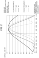
- Fig. 2 is a graph illustrating an example of modulation transfer function (MTF) characteristics in the anamorphic lens.
- MTF is one of the indexes for evaluating the performance of a lens and indicates as a spatial frequency characteristic how faithfully the contrast of the subject can be reproduced in order to know an image formation performance of the lens.
- the MTF at a specific spatial frequency corresponds to a resolution and indicates that the larger the value, the higher the resolution.
- the horizontal axis indicates a paraxial ray position of the optical system in the horizontal direction.
- the vertical axis indicates the MTF.
- a solid line indicates the MTF characteristics in the horizontal direction
- a broken line indicates the MTF characteristics in the vertical direction.
- MTF characteristics at Fl low frequency
- Fh high frequency
- the anamorphic lens generally has a shorter focal length and a greater depth of field, in the horizontal direction than in the vertical direction.
- the horizontal axis of the graph in Fig. 2 is the amount of defocus
- the MTF characteristic is less likely to decrease in the horizontal direction even if the amount of defocus is the same in the vertical and horizontal directions.
- the inclination of the MTF characteristic differs between the vertical and horizontal directions. Therefore, it is possible to mention that an image is blurred faster in the vertical direction compared to the horizontal direction.
- the MTF tends to decrease so that the image looks blurred.
- a range of the amount of defocus which is regarded to be in focus, is wider in the horizontal direction compared to the vertical direction.
- a peak position of the MTF characteristic differs between the vertical and horizontal directions. While up to depend on the optical design, it is difficult to match the peak positions of the MTF characteristics between the vertical and horizontal directions under all conditions. Note that the MTF characteristics between the vertical and horizontal directions also change depending on a frequency of the subject. Note that it is assumed that the vertical direction and the horizontal direction are orthogonal to each other.
- anamorphic lens Due to such characteristics of the anamorphic lens, various functions including a function based on autofocus may not be normally used in the image capture device provided with the anamorphic lens in some cases. Therefore, by performing the process described below, even in the image capture device provided with the anamorphic lens, the user can use the functions equipped with the general image capture device without any special operation or handling.
- the first aspect is an in-focus mark displaying process in the image capture device 100 provided with the anamorphic lens 101.
- the in-focus mark is, for example, a circular icon indicating the in-focus state, which is superimposed and displayed on a through image on the display unit 110 during imaging with the image capture device 100.
- Fig. 3 illustrates a mode of an icon form and lighting up, and the meaning of the mode.
- an in-focus mark 1000 is lighting up in a first mode as illustrated in Fig. 3A
- the case indicates that the subject is in focus.
- the case indicates that the subject is out of focus.
- the case indicates that the subject is in focus, but the focus position changes according to a movement of the subject.
- the case indicates a state that is on the way of focusing and looking for a position in focus.
- the form and lighting mode of the in-focus mark 1000 are not limited to those illustrated in Fig. 3 .
- the shape is not limited to a circular shape, and other shapes may be used.
- different states may be indicated by a change in shape, a change in color, and the like.
- amount of focus deviation in the description of the flowchart below is an amount of focus deviation calculated by the processing in autofocus, and, in a case where the amount of focus deviation differs between the vertical and horizontal directions, one value is determined by a predetermined method.
- Examples of the method of determining either one of the amounts of focus deviation are a method of taking an average of the amounts of focus deviation in the vertical and the horizontal directions, a method of making the determination on the basis of the MTF characteristics, a method of making the determination on the basis of the MTF characteristics and the inclination of the subject, a method of making the determination on the basis of indicators such as a degree of reliability, a degree of similarity, and the like calculated by the sum of absolute difference (SAD) as one of the methods for calculating the degree of similarity of block matching used for detection of phase-detection AF, a method of prioritizing the vertical direction, and the like.
- SAD sum of absolute difference
- step S101 it is determined whether or not it is impossible to detect focus. In a case where it is possible to detect focus, the process proceeds to step S102 (No in step S101).
- step S102 it is determined whether or not the image capture device 100 is in a mode of continuing focusing. This is set by the user or automatically determined and can be determined by referring to the setting information of the image capture device 100.
- step S103 it is determined whether or not the focus is being locked. In a case where the focus is not being locked, the process proceeds to step S104 (No in step S103).
- step S104 the amount of focus deviation is compared with a first comparison formula presented in [Formula 1] below.
- the parameter d1 is a constant for determining the allowable focus width.
- the F value in the horizontal direction and the F value in the vertical direction correspond to the parameters being predetermined in the claims.
- [Formula 1] takes the geometric mean in the horizontal and vertical directions, but it is not limited to this, and there is also a method of calculating with an arithmetic mean or a weighted mean that is weighted in the horizontal direction/vertical direction.
- step S104 the process proceeds to step S105 (Yes in step S104). Then, in step S105, the signal processing device 150 performs processing so that the in-focus mark 1000 is not displayed on the display unit 110.
- step S103 In a case where the focus is being locked in step S103, the process proceeds to step S106, and the in-focus mark 1000 indicating that the subject is in focus, which is illustrated in Fig. 3A , is displayed on the display unit 110. It is because if the focus can be detected and the focus is being fixed, it is possible to determine to be in the state in which the subject is in focus.
- the in-focus mark 1000 indicating that the subject is in focus is displayed on the display unit 110 in step S106. It is because, in the determination in step S104, in a case where the amount of focus deviation is equal to or less than the first comparison formula, it is possible to determine that the amount of focus deviation is small and the subject is in focus.
- step S107 the amount of focus deviation is compared with a second comparison formula presented in [Formula 2] below. Amount of focus deviation ⁇ ⁇ (F value in the horizontal direction ⁇ F value in the vertical direction) ⁇ d2
- the parameter d2 is a constant for determining the allowable focus width.
- the F value in the horizontal direction and the F value in the vertical direction correspond to the parameters being predetermined in the claims.
- [Formula 2] takes the geometric mean in the horizontal and vertical directions, but it is not limited to this, and there is also a method of calculating with an arithmetic mean or a weighted mean that is weighted in the horizontal direction/vertical direction.
- step S108 the in-focus mark 1000 indicating "being a state being on the way to focusing and searching for a position that is in-focus", which is illustrated in Fig. 3D , is displayed on the display unit 110. It is because the case that it is possible to detect focus and the amount of focus deviation is equal to or larger than the first comparison formula while trying to focus indicates that the focus deviation is large, and it is possible to say that the subject is not currently in focus.
- step S109 the in-focus mark 1000 indicating "the subject is in focus, but the focus position changes according to a movement of the subject", which is illustrated in Fig. 3C , is displayed on the display unit 110. It is because the case that the amount of focus deviation is equal to or less than the first comparison formula indicates that the focus deviation is small, and it is possible to say that the subject is currently in focus.
- step S101 The explanation returns to step S101.
- the process in which it is impossible to detect focus in step S101 proceeds to step S110 (Yes in step S101), and the in-focus mark 1000 indicating that the subject is not in focus illustrated in Fig. 3B is displayed on the display unit 110.
- the first aspect of processing in the signal processing device 150 is configured as described above. According to the first aspect of the present embodiment, the user can use the function of displaying the in-focus mark in the image capture device 100 provided with the anamorphic lens 101 without any special operation or handling.
- the second aspect is a process of arranging and displaying the in-focus area in the image capture device 100 provided with the anamorphic lens 101.
- the arrangement and display of the in-focus area means that a plurality of in-focus areas, which is detection ranges for autofocus on the input image, is arranged on the image and superimposed on the through image (the monitoring image) displayed on the display unit 110 to display the in-focus area that overlaps the in-focus subject.
- the detection unit 113 of the image capture device 100 detects a state of in-focus of the subject (a degree of in-focus) in each in-focus area and acquires defocus information indicating an amount of deviation from a focal point in all of the in-focus areas. With this display of the in-focus area, the user can confirm which part of the subject is currently in focus by looking at the display unit 110.
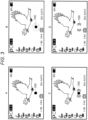
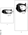
- Fig. 5A illustrates an image in a state of being compressed in the horizontal direction by the anamorphic lens 101 at the time of imaging by the image capture device 100 and an arrangement of an in-focus area 2000 with respect to the image.
- Fig. 5B illustrates a state in which the image compressed in the horizontal direction by the anamorphic lens 101 is stretched in the horizontal direction to reproduce the image at the time of reproduction and the arrangement of the in-focus area 2000 with respect to the image.
- one of the plurality of in-focus areas is designated by the sign 2000, but the one only is not the in-focus area, but all of the rectangular frames in dash lines (solid lines in Fig. 9 ) illustrated superimposed on the image are the in-focus areas.
- the image capture device 100 has a function of confirming both a compressed state and a stretched state at the time of imaging and shall be possible to switch and display the compressed state illustrated in Fig. 5A and the stretched state illustrated in Fig. 5B displayed on the display unit 110 and to present to the user.
- the anamorphic lens 101 is a lens having different focal lengths in the vertical and horizontal directions, and an image is recorded in a state that the image is compressed in the horizontal direction when imaging. Then, by stretching the image in the horizontal direction when reproducing the image, a horizontally long natural image being equal to or larger than an aspect of a recording element is realized.
- the state of the in-focus area 2000 (an arrangement interval (a placement density)) is set to be different between the state of the image compressed in the horizontal direction illustrated in Fig. 5A and the state of the image stretched in the horizontal direction illustrated in Fig. 5B . Therefore, the in-focus areas 2000 become to be arranged more densely in the state of the image compressed in the horizontal direction illustrated in Fig. 5A than in the state of the image stretched in the horizontal direction illustrated in Fig. 5B .
- the arrangement of the in-focus area 2000 is changed as illustrated in Fig. 5B so that it is possible to cover the entire image in a similar way by widening the horizontal spacing of the in-focus area 2000 in the stretched state.
- the arrangement interval of the in-focus area 2000 is increased corresponding to the ratio of the magnification of zoom for the stretching in the horizontal direction.
- the arrangement of the in-focus area 2000 is compressed as much as 50 percent in the horizontal direction in the state of Fig. 5A compared to the state of Fig. 5B .
- the change of the state of the in-focus area 2000 may not only be the change of the arrangement interval of the in-focus area 2000 as described above but also be a change of the number of in-focus areas 2000 as illustrated in Fig. 7 .
- the number of in-focus areas 2000 in the horizontal direction is increased in the stretched state illustrated in Fig. 7B as compared with the compressed state illustrated in Fig. 7A .
- the state of the in-focus area 2000 may be changed by changing the shape of the in-focus area 2000, changing the area in which the in-focus area 2000 is arranged, or the like.
- a flow of the process of displaying the in-focus area in the image capture device 100 provided with the anamorphic lens 101 as illustrated in Fig. 9 will be described.
- This process is performed for each of all the in-focus areas 2000, and is a process for determining whether or not superimposing each in-focus area 2000 on the through image and displaying on the display unit 110.
- the in-focus area displayed superimposed on the through image is the in-focus area corresponding to the position in which the subject is in focus in the image.
- step S201 it is determined whether or not the in-focus area is an in-focus area that overlaps the subject on which the user desires to focus.
- This determination can be made using, for example, subject detection, person detection, distance map of the image, or the like. For example, in a case where a person detected by person detection overlaps the in-focus area, since the person is usually the subject that the user desires to focus on in a photograph, it is determined that the in-focus area overlaps the subject on which the user desires to focus. On the other hand, in a case where the detected person does not overlap the in-focus area, it is determined that the in-focus area does not overlap the subject on which the user desires to focus.
- step S202 a process in which the in-focus area 2000 is not displayed on the display unit 110 is performed.
- step S201 in a case where the in-focus area is the in-focus area that overlaps the subject on which the user desires to focus, the process proceeds to step S203 (Yes in step S201).
- step S203 it is determined whether or not it is impossible to detect focus. In a case where it is not possible to detect focus, the process proceeds to step S202 (Yes in step S203), and a process in which the in-focus area is not displayed on the display unit 110 is performed.
- step S204 the amount of focus deviation is compared with a third comparison formula presented in [Formula 3] below.
- the parameter d3 is a constant for determining the allowable focus width.
- the F value in the horizontal direction and the F value in the vertical direction correspond to the parameters being predetermined in the claims.
- [Formula 3] takes the geometric mean in the horizontal and vertical directions, but it is not limited to this, and there is also a method of calculating with an arithmetic mean or a weighted mean that is weighted in the horizontal direction/vertical direction.
- step S202 (No in step S204), and a process that the in-focus area is not displayed on the display unit 110 is performed.
- step S205 the process proceeds to step S205 (Yes in step S204), and because the subject is in focus in that in-focus area, a process of displaying that in-focus area on the display unit 110 is performed.
- a face detection frame 4000 which is an icon displayed according to a face 3000 detected in the image by the face detection function during imaging is considered.
- the shape of the face detection frame 4000 is changed according to the ratio of the magnification of zoom. Therefore, at the time of confirming the stretched state of the image, the face detection frame 4000 is also displayed in the shape and size according to the shape and size of the face 3000.
- the second aspect of the processing in the signal processing device 150 is configured as described above. According to the second aspect of the present embodiment, the user can use the function of displaying the in-focus area in the image capture device 100 provided with the anamorphic lens 101 without any special operation or handling.
- the embodiment of the present technology is configured. According to this embodiment, even in the image capture device 100 provided with the anamorphic lens 101, it is possible to use the functions equipped with an ordinary camera, displaying the in-focus mark, displaying the in-focus area, and detecting the subject, without any special handling.
Landscapes
- Engineering & Computer Science (AREA)
- Multimedia (AREA)
- Signal Processing (AREA)
- Physics & Mathematics (AREA)
- General Physics & Mathematics (AREA)
- Computer Vision & Pattern Recognition (AREA)
- Optics & Photonics (AREA)
- Studio Devices (AREA)
- Automatic Focus Adjustment (AREA)
- Focusing (AREA)
- Indication In Cameras, And Counting Of Exposures (AREA)
Claims (4)
- Signalverarbeitungsvorrichtung (150), die für einen Anzeigeprozess in einer Anzeigeeinheit (110) auf einer Basis von Parametern konfiguriert ist, die in einer mit einer anamorphotischen Linse versehenen Bilderfassungsvorrichtung (100) vorbestimmt sind,wobei die Signalverarbeitungsvorrichtung (150) konfiguriert ist, um ein Symbol anzuzeigen, das einen fokussierten Zustand auf der Anzeigeeinheit (110) als den Anzeigeprozess angibt,wobei die Parameter ein Blendenwert, F-Wert, in einer Richtung, die einer vertikalen Richtung der anamorphotischen Linse entspricht, und ein F-Wert in einer Richtung, die einer horizontalen Richtung der anamorphotischen Linse entspricht, sind, undwobei die Signalverarbeitungsvorrichtung (150) konfiguriert ist, um einen Modus zum Anzeigen des Symbols auf einer Basis eines Vergleichsergebnisses zwischen einem Maß an Fokusabweichung und einem Durchschnitt des F-Werts in der Richtung, die der vertikalen Richtung entspricht, und des F-Werts in der Richtung, die der horizontalen Richtung entspricht, multipliziert mit einem Parameter d zu bestimmen, wobei der Durchschnitt entweder ein geometrischer Durchschnitt, ein arithmetischer Durchschnitt oder ein gewichteter Durchschnitt ist, der Parameter d eine Konstante zum Bestimmen einer zulässigen Fokusbreite ist und das Maß an Fokusabweichung die Differenz zwischen einer aktuellen Fokusposition und einer durch einen Autofokus bestimmten fokussierten Position der anamorphotischen Linse ist.
- Signalverarbeitungsverfahren, das einen Anzeigeprozess in einer Anzeigeeinheit (110) auf einer Basis von Parametern durchführt, die in einer mit einer anamorphotischen Linse versehenen Bilderfassungsvorrichtung (100) vorbestimmt sind, das Signalverarbeitungsverfahren umfassendAnzeigen eines Symbols, das einen fokussierten Zustand angibt, auf der Anzeigeeinheit als den Anzeigeprozess, wobei die Parameter ein Blendenwert, F-Wert, in einer Richtung, die einer vertikalen Richtung der anamorphotischen Linse entspricht, und ein F-Wert in einer Richtung, die einer horizontalen Richtung der anamorphotischen Linse entspricht, sind,Bestimmen eines Modus zum Anzeigen des Symbols auf einer Basis eines Vergleichsergebnisses zwischen einem Maß an Fokusabweichung und einem Durchschnitt des F-Werts in der Richtung, die der vertikalen Richtung entspricht, und des F-Werts in der Richtung, die der horizontalen Richtung entspricht, multipliziert mit einem Parameter d, wobei der Durchschnitt entweder ein geometrischer Durchschnitt, ein arithmetischer Durchschnitt oder ein gewichteter Durchschnitt ist, der Parameter d eine Konstante zum Bestimmen der zulässigen Fokusbreite ist und das Maß an Fokusabweichung die Differenz zwischen einer aktuellen Fokusposition und einer durch einen Autofokus bestimmten fokussierten Position der anamorphotischen Linse ist.
- Signalverarbeitungsprogramm, umfassend Anweisungen, die, wenn sie durch einen Computer einer Signalverarbeitungsvorrichtung nach Anspruch 1 ausgeführt werden, bewirken, dass der Computer das Verfahren nach Anspruch 2 durchführt.
- Bilderfassungsvorrichtung (100), umfassend:eine anamorphotische Linse; undeine Signalverarbeitungsvorrichtung (150) nach Anspruch 1, die konfiguriert ist, um einen Anzeigeprozess in einer Anzeigeeinheit (110) auf einer Basis von Parameter, die vorbestimmt sind, durchzuführen.
Applications Claiming Priority (2)
| Application Number | Priority Date | Filing Date | Title |
|---|---|---|---|
| JP2018160797 | 2018-08-29 | ||
| PCT/JP2019/028410 WO2020044844A1 (ja) | 2018-08-29 | 2019-07-19 | 信号処理装置、信号処理方法、信号処理プログラムおよび撮像装置 |
Publications (3)
| Publication Number | Publication Date |
|---|---|
| EP3845945A1 EP3845945A1 (de) | 2021-07-07 |
| EP3845945A4 EP3845945A4 (de) | 2022-01-12 |
| EP3845945B1 true EP3845945B1 (de) | 2025-04-23 |
Family
ID=69645114
Family Applications (1)
| Application Number | Title | Priority Date | Filing Date |
|---|---|---|---|
| EP19856159.9A Active EP3845945B1 (de) | 2018-08-29 | 2019-07-19 | Signalverarbeitungsvorrichtung, signalverarbeitungsverfahren, signalverarbeitungsprogramm und bildaufnahmevorrichtung |
Country Status (5)
| Country | Link |
|---|---|
| US (1) | US11467482B2 (de) |
| EP (1) | EP3845945B1 (de) |
| JP (1) | JP7415930B2 (de) |
| CN (1) | CN112543883B (de) |
| WO (1) | WO2020044844A1 (de) |
Families Citing this family (2)
| Publication number | Priority date | Publication date | Assignee | Title |
|---|---|---|---|---|
| KR20240116286A (ko) | 2023-01-20 | 2024-07-29 | 삼성전자주식회사 | 촬상 장치 및 상기 촬상 장치를 포함하는 촬상 시스템 |
| US20240381001A1 (en) * | 2023-05-11 | 2024-11-14 | SoftEye, Inc. | Applications for anamorphic lenses |
Family Cites Families (14)
| Publication number | Priority date | Publication date | Assignee | Title |
|---|---|---|---|---|
| EP0510642B1 (de) * | 1991-04-25 | 1998-07-22 | Canon Kabushiki Kaisha | Bildüberlagerungssystem für unterschiedliche Bildseitenverhältnisse |
| JPH0614239A (ja) * | 1992-06-29 | 1994-01-21 | Canon Inc | 自動焦点調節装置及び方法並びにアナモフィック・レンズ・ユニット |
| JP3278206B2 (ja) | 1992-08-31 | 2002-04-30 | キヤノン株式会社 | 撮像装置及びその方法 |
| JP2004297751A (ja) | 2003-02-07 | 2004-10-21 | Sharp Corp | 合焦状態表示装置及び合焦状態表示方法 |
| US20050166249A1 (en) * | 2004-01-26 | 2005-07-28 | Wiatt Kettle | Fitting video feed to a display device |
| TWI388206B (zh) * | 2005-09-14 | 2013-03-01 | 松下電器產業股份有限公司 | 攝影裝置、固態攝影元件、影像生成方法 |
| TW200922319A (en) * | 2007-11-12 | 2009-05-16 | Optoma Corp | Method and system for switching projection ratios using a lens scaler |
| JP5146295B2 (ja) * | 2008-12-15 | 2013-02-20 | ソニー株式会社 | 撮像装置および合焦制御方法 |
| JP5409205B2 (ja) * | 2009-08-31 | 2014-02-05 | キヤノン株式会社 | 撮像装置及びその制御方法 |
| JP2017175304A (ja) * | 2016-03-23 | 2017-09-28 | キヤノン株式会社 | 撮像装置 |
| JP6727989B2 (ja) * | 2016-08-31 | 2020-07-22 | キヤノン株式会社 | 画像処理装置およびその制御方法 |
| JP6746468B2 (ja) | 2016-11-02 | 2020-08-26 | キヤノン株式会社 | 撮像装置及びその表示制御方法、並びにプログラム |
| JP6529533B2 (ja) * | 2017-03-21 | 2019-06-12 | キヤノン株式会社 | 撮像装置、撮像装置の制御方法、及び、プログラム |
| JP6513126B2 (ja) * | 2017-05-16 | 2019-05-15 | キヤノン株式会社 | 表示制御装置とその制御方法及びプログラム |
-
2019
- 2019-07-19 US US17/250,659 patent/US11467482B2/en active Active
- 2019-07-19 EP EP19856159.9A patent/EP3845945B1/de active Active
- 2019-07-19 CN CN201980052989.1A patent/CN112543883B/zh active Active
- 2019-07-19 JP JP2020540139A patent/JP7415930B2/ja active Active
- 2019-07-19 WO PCT/JP2019/028410 patent/WO2020044844A1/ja not_active Ceased
Also Published As
| Publication number | Publication date |
|---|---|
| JP7415930B2 (ja) | 2024-01-17 |
| JPWO2020044844A1 (ja) | 2021-08-26 |
| US20220121100A1 (en) | 2022-04-21 |
| US11467482B2 (en) | 2022-10-11 |
| CN112543883B (zh) | 2023-10-24 |
| WO2020044844A1 (ja) | 2020-03-05 |
| CN112543883A (zh) | 2021-03-23 |
| EP3845945A1 (de) | 2021-07-07 |
Similar Documents
| Publication | Publication Date | Title |
|---|---|---|
| JP6248412B2 (ja) | 撮像装置、撮像方法、プログラム | |
| US20200267308A1 (en) | Imaging capturing device and imaging capturing method | |
| JP5054583B2 (ja) | 撮像装置 | |
| US9374520B2 (en) | Digital image processing apparatus and method of controlling the same | |
| JP2014222801A5 (de) | ||
| US9025032B2 (en) | Imaging system and pixel signal readout method | |
| CN101285989B (zh) | 自动对焦装置、图像拾取装置和自动对焦方法 | |
| CN104205797B (zh) | 摄像装置 | |
| US20190149739A1 (en) | Imaging apparatus, lens apparatus, and method for controlling the same | |
| CN108293087B (zh) | 摄影装置及其控制方法 | |
| WO2017037978A1 (ja) | 検出装置、検出方法、検出プログラムおよび撮像装置 | |
| JPH11298791A (ja) | 電子カメラ | |
| US7941041B2 (en) | Image pickup apparatus | |
| CN104170366B (zh) | 成像设备和图像处理方法 | |
| EP3845945B1 (de) | Signalverarbeitungsvorrichtung, signalverarbeitungsverfahren, signalverarbeitungsprogramm und bildaufnahmevorrichtung | |
| US11792534B2 (en) | Signal processing device, signal processing method, and image capture device | |
| JP5273965B2 (ja) | 撮像装置 | |
| JP2008113466A (ja) | 電子カメラ | |
| JP2004341095A (ja) | オートフォーカスカメラ | |
| JP5196768B2 (ja) | 撮像装置 | |
| JP2010074415A (ja) | 撮像装置、画像表示方法および画像表示プログラム | |
| JP2001255452A (ja) | 自動合焦装置、デジタルカメラ、および携帯情報入力装置 | |
| JP6645614B2 (ja) | 撮像装置及び電子機器 | |
| JP2009118515A (ja) | 電子カメラ | |
| JP5610889B2 (ja) | 焦点調節装置及び方法 |
Legal Events
| Date | Code | Title | Description |
|---|---|---|---|
| STAA | Information on the status of an ep patent application or granted ep patent |
Free format text: STATUS: THE INTERNATIONAL PUBLICATION HAS BEEN MADE |
|
| STAA | Information on the status of an ep patent application or granted ep patent |
Free format text: STATUS: REQUEST FOR EXAMINATION WAS MADE |
|
| PUAI | Public reference made under article 153(3) epc to a published international application that has entered the european phase |
Free format text: ORIGINAL CODE: 0009012 |
|
| 17P | Request for examination filed |
Effective date: 20210205 |
|
| AK | Designated contracting states |
Kind code of ref document: A1 Designated state(s): AL AT BE BG CH CY CZ DE DK EE ES FI FR GB GR HR HU IE IS IT LI LT LU LV MC MK MT NL NO PL PT RO RS SE SI SK SM TR |
|
| RAP3 | Party data changed (applicant data changed or rights of an application transferred) |
Owner name: SONY GROUP CORPORATION |
|
| RIC1 | Information provided on ipc code assigned before grant |
Ipc: G02B 13/08 20060101ALI20210906BHEP Ipc: G03B 17/18 20210101ALI20210906BHEP Ipc: G03B 13/36 20210101ALI20210906BHEP Ipc: G02B 7/28 20210101ALI20210906BHEP Ipc: H04N 5/232 20060101AFI20210906BHEP |
|
| REG | Reference to a national code |
Ref country code: DE Ipc: H04N0005232000 Ref legal event code: R079 Ref document number: 602019069120 Country of ref document: DE Free format text: PREVIOUS MAIN CLASS: G02B0007280000 |
|
| DAV | Request for validation of the european patent (deleted) | ||
| DAX | Request for extension of the european patent (deleted) | ||
| A4 | Supplementary search report drawn up and despatched |
Effective date: 20211213 |
|
| RIC1 | Information provided on ipc code assigned before grant |
Ipc: G02B 13/08 20060101ALI20211207BHEP Ipc: G03B 17/18 20210101ALI20211207BHEP Ipc: G03B 13/36 20210101ALI20211207BHEP Ipc: G02B 7/28 20210101ALI20211207BHEP Ipc: H04N 5/232 20060101AFI20211207BHEP |
|
| STAA | Information on the status of an ep patent application or granted ep patent |
Free format text: STATUS: EXAMINATION IS IN PROGRESS |
|
| 17Q | First examination report despatched |
Effective date: 20240206 |
|
| REG | Reference to a national code |
Ref country code: DE Ref legal event code: R079 Ipc: G03B0013360000 Ref document number: 602019069120 Country of ref document: DE Free format text: PREVIOUS MAIN CLASS: H04N0005232000 |
|
| GRAP | Despatch of communication of intention to grant a patent |
Free format text: ORIGINAL CODE: EPIDOSNIGR1 |
|
| STAA | Information on the status of an ep patent application or granted ep patent |
Free format text: STATUS: GRANT OF PATENT IS INTENDED |
|
| RIC1 | Information provided on ipc code assigned before grant |
Ipc: H04N 23/67 20230101ALI20241107BHEP Ipc: H04N 23/663 20230101ALI20241107BHEP Ipc: H04N 23/63 20230101ALI20241107BHEP Ipc: G03B 37/06 20210101ALI20241107BHEP Ipc: G03B 17/20 20210101ALI20241107BHEP Ipc: G02B 7/36 20210101ALI20241107BHEP Ipc: G03B 13/36 20210101AFI20241107BHEP |
|
| INTG | Intention to grant announced |
Effective date: 20241119 |
|
| GRAS | Grant fee paid |
Free format text: ORIGINAL CODE: EPIDOSNIGR3 |
|
| GRAA | (expected) grant |
Free format text: ORIGINAL CODE: 0009210 |
|
| STAA | Information on the status of an ep patent application or granted ep patent |
Free format text: STATUS: THE PATENT HAS BEEN GRANTED |
|
| P01 | Opt-out of the competence of the unified patent court (upc) registered |
Free format text: CASE NUMBER: APP_9537/2025 Effective date: 20250226 |
|
| AK | Designated contracting states |
Kind code of ref document: B1 Designated state(s): AL AT BE BG CH CY CZ DE DK EE ES FI FR GB GR HR HU IE IS IT LI LT LU LV MC MK MT NL NO PL PT RO RS SE SI SK SM TR |
|
| REG | Reference to a national code |
Ref country code: GB Ref legal event code: FG4D |
|
| REG | Reference to a national code |
Ref country code: CH Ref legal event code: EP |
|
| REG | Reference to a national code |
Ref country code: DE Ref legal event code: R096 Ref document number: 602019069120 Country of ref document: DE |
|
| REG | Reference to a national code |
Ref country code: IE Ref legal event code: FG4D |
|
| PGFP | Annual fee paid to national office [announced via postgrant information from national office to epo] |
Ref country code: GB Payment date: 20250619 Year of fee payment: 7 |
|
| PGFP | Annual fee paid to national office [announced via postgrant information from national office to epo] |
Ref country code: NL Payment date: 20250620 Year of fee payment: 7 |
|
| REG | Reference to a national code |
Ref country code: NL Ref legal event code: FP |
|
| REG | Reference to a national code |
Ref country code: AT Ref legal event code: MK05 Ref document number: 1788308 Country of ref document: AT Kind code of ref document: T Effective date: 20250423 |
|
| PG25 | Lapsed in a contracting state [announced via postgrant information from national office to epo] |
Ref country code: PT Free format text: LAPSE BECAUSE OF FAILURE TO SUBMIT A TRANSLATION OF THE DESCRIPTION OR TO PAY THE FEE WITHIN THE PRESCRIBED TIME-LIMIT Effective date: 20250825 Ref country code: ES Free format text: LAPSE BECAUSE OF FAILURE TO SUBMIT A TRANSLATION OF THE DESCRIPTION OR TO PAY THE FEE WITHIN THE PRESCRIBED TIME-LIMIT Effective date: 20250423 Ref country code: FI Free format text: LAPSE BECAUSE OF FAILURE TO SUBMIT A TRANSLATION OF THE DESCRIPTION OR TO PAY THE FEE WITHIN THE PRESCRIBED TIME-LIMIT Effective date: 20250423 |
|
| PGFP | Annual fee paid to national office [announced via postgrant information from national office to epo] |
Ref country code: DE Payment date: 20250620 Year of fee payment: 7 |
|
| REG | Reference to a national code |
Ref country code: LT Ref legal event code: MG9D |
|
| PG25 | Lapsed in a contracting state [announced via postgrant information from national office to epo] |
Ref country code: NO Free format text: LAPSE BECAUSE OF FAILURE TO SUBMIT A TRANSLATION OF THE DESCRIPTION OR TO PAY THE FEE WITHIN THE PRESCRIBED TIME-LIMIT Effective date: 20250723 Ref country code: GR Free format text: LAPSE BECAUSE OF FAILURE TO SUBMIT A TRANSLATION OF THE DESCRIPTION OR TO PAY THE FEE WITHIN THE PRESCRIBED TIME-LIMIT Effective date: 20250724 |
|
| PG25 | Lapsed in a contracting state [announced via postgrant information from national office to epo] |
Ref country code: PL Free format text: LAPSE BECAUSE OF FAILURE TO SUBMIT A TRANSLATION OF THE DESCRIPTION OR TO PAY THE FEE WITHIN THE PRESCRIBED TIME-LIMIT Effective date: 20250423 |
|
| PG25 | Lapsed in a contracting state [announced via postgrant information from national office to epo] |
Ref country code: BG Free format text: LAPSE BECAUSE OF FAILURE TO SUBMIT A TRANSLATION OF THE DESCRIPTION OR TO PAY THE FEE WITHIN THE PRESCRIBED TIME-LIMIT Effective date: 20250423 |
|
| PG25 | Lapsed in a contracting state [announced via postgrant information from national office to epo] |
Ref country code: HR Free format text: LAPSE BECAUSE OF FAILURE TO SUBMIT A TRANSLATION OF THE DESCRIPTION OR TO PAY THE FEE WITHIN THE PRESCRIBED TIME-LIMIT Effective date: 20250423 |
|
| PG25 | Lapsed in a contracting state [announced via postgrant information from national office to epo] |
Ref country code: AT Free format text: LAPSE BECAUSE OF FAILURE TO SUBMIT A TRANSLATION OF THE DESCRIPTION OR TO PAY THE FEE WITHIN THE PRESCRIBED TIME-LIMIT Effective date: 20250423 |
|
| PG25 | Lapsed in a contracting state [announced via postgrant information from national office to epo] |
Ref country code: RS Free format text: LAPSE BECAUSE OF FAILURE TO SUBMIT A TRANSLATION OF THE DESCRIPTION OR TO PAY THE FEE WITHIN THE PRESCRIBED TIME-LIMIT Effective date: 20250723 |
|
| PG25 | Lapsed in a contracting state [announced via postgrant information from national office to epo] |
Ref country code: IS Free format text: LAPSE BECAUSE OF FAILURE TO SUBMIT A TRANSLATION OF THE DESCRIPTION OR TO PAY THE FEE WITHIN THE PRESCRIBED TIME-LIMIT Effective date: 20250823 |
|
| PG25 | Lapsed in a contracting state [announced via postgrant information from national office to epo] |
Ref country code: LV Free format text: LAPSE BECAUSE OF FAILURE TO SUBMIT A TRANSLATION OF THE DESCRIPTION OR TO PAY THE FEE WITHIN THE PRESCRIBED TIME-LIMIT Effective date: 20250423 |
|
| PG25 | Lapsed in a contracting state [announced via postgrant information from national office to epo] |
Ref country code: DK Free format text: LAPSE BECAUSE OF FAILURE TO SUBMIT A TRANSLATION OF THE DESCRIPTION OR TO PAY THE FEE WITHIN THE PRESCRIBED TIME-LIMIT Effective date: 20250423 Ref country code: SM Free format text: LAPSE BECAUSE OF FAILURE TO SUBMIT A TRANSLATION OF THE DESCRIPTION OR TO PAY THE FEE WITHIN THE PRESCRIBED TIME-LIMIT Effective date: 20250423 |
|
| PG25 | Lapsed in a contracting state [announced via postgrant information from national office to epo] |
Ref country code: CZ Free format text: LAPSE BECAUSE OF FAILURE TO SUBMIT A TRANSLATION OF THE DESCRIPTION OR TO PAY THE FEE WITHIN THE PRESCRIBED TIME-LIMIT Effective date: 20250423 |
|
| PG25 | Lapsed in a contracting state [announced via postgrant information from national office to epo] |
Ref country code: EE Free format text: LAPSE BECAUSE OF FAILURE TO SUBMIT A TRANSLATION OF THE DESCRIPTION OR TO PAY THE FEE WITHIN THE PRESCRIBED TIME-LIMIT Effective date: 20250423 |
|
| REG | Reference to a national code |
Ref country code: DE Ref legal event code: R097 Ref document number: 602019069120 Country of ref document: DE |
|
| PG25 | Lapsed in a contracting state [announced via postgrant information from national office to epo] |
Ref country code: SK Free format text: LAPSE BECAUSE OF FAILURE TO SUBMIT A TRANSLATION OF THE DESCRIPTION OR TO PAY THE FEE WITHIN THE PRESCRIBED TIME-LIMIT Effective date: 20250423 Ref country code: RO Free format text: LAPSE BECAUSE OF FAILURE TO SUBMIT A TRANSLATION OF THE DESCRIPTION OR TO PAY THE FEE WITHIN THE PRESCRIBED TIME-LIMIT Effective date: 20250423 |
|
| PG25 | Lapsed in a contracting state [announced via postgrant information from national office to epo] |
Ref country code: IT Free format text: LAPSE BECAUSE OF FAILURE TO SUBMIT A TRANSLATION OF THE DESCRIPTION OR TO PAY THE FEE WITHIN THE PRESCRIBED TIME-LIMIT Effective date: 20250423 |
|
| REG | Reference to a national code |
Ref country code: CH Ref legal event code: H13 Free format text: ST27 STATUS EVENT CODE: U-0-0-H10-H13 (AS PROVIDED BY THE NATIONAL OFFICE) Effective date: 20260224 |
|
| PLBE | No opposition filed within time limit |
Free format text: ORIGINAL CODE: 0009261 |
|
| STAA | Information on the status of an ep patent application or granted ep patent |
Free format text: STATUS: NO OPPOSITION FILED WITHIN TIME LIMIT |
|
| REG | Reference to a national code |
Ref country code: CH Ref legal event code: L10 Free format text: ST27 STATUS EVENT CODE: U-0-0-L10-L00 (AS PROVIDED BY THE NATIONAL OFFICE) Effective date: 20260304 |
|
| PG25 | Lapsed in a contracting state [announced via postgrant information from national office to epo] |
Ref country code: LU Free format text: LAPSE BECAUSE OF NON-PAYMENT OF DUE FEES Effective date: 20250719 |
|
| REG | Reference to a national code |
Ref country code: BE Ref legal event code: MM Effective date: 20250731 |
|
| 26N | No opposition filed |
Effective date: 20260126 |
|
| PG25 | Lapsed in a contracting state [announced via postgrant information from national office to epo] |
Ref country code: BE Free format text: LAPSE BECAUSE OF NON-PAYMENT OF DUE FEES Effective date: 20250731 |
|
| PG25 | Lapsed in a contracting state [announced via postgrant information from national office to epo] |
Ref country code: FR Free format text: LAPSE BECAUSE OF NON-PAYMENT OF DUE FEES Effective date: 20250731 |