EP3843369B1 - Relaisvorrichtung und verfahren zur weiterleitung von sprachsignalen - Google Patents
Relaisvorrichtung und verfahren zur weiterleitung von sprachsignalen Download PDFInfo
- Publication number
- EP3843369B1 EP3843369B1 EP19864264.7A EP19864264A EP3843369B1 EP 3843369 B1 EP3843369 B1 EP 3843369B1 EP 19864264 A EP19864264 A EP 19864264A EP 3843369 B1 EP3843369 B1 EP 3843369B1
- Authority
- EP
- European Patent Office
- Prior art keywords
- voice signal
- telephone
- destination
- communication
- transfer control
- Prior art date
- Legal status (The legal status is an assumption and is not a legal conclusion. Google has not performed a legal analysis and makes no representation as to the accuracy of the status listed.)
- Active
Links
Images


Classifications
-
- H—ELECTRICITY
- H04—ELECTRIC COMMUNICATION TECHNIQUE
- H04L—TRANSMISSION OF DIGITAL INFORMATION, e.g. TELEGRAPHIC COMMUNICATION
- H04L65/00—Network arrangements, protocols or services for supporting real-time applications in data packet communication
- H04L65/40—Support for services or applications
- H04L65/4061—Push-to services, e.g. push-to-talk or push-to-video
-
- H—ELECTRICITY
- H04—ELECTRIC COMMUNICATION TECHNIQUE
- H04L—TRANSMISSION OF DIGITAL INFORMATION, e.g. TELEGRAPHIC COMMUNICATION
- H04L65/00—Network arrangements, protocols or services for supporting real-time applications in data packet communication
- H04L65/10—Architectures or entities
- H04L65/1045—Proxies, e.g. for session initiation protocol [SIP]
-
- H—ELECTRICITY
- H04—ELECTRIC COMMUNICATION TECHNIQUE
- H04L—TRANSMISSION OF DIGITAL INFORMATION, e.g. TELEGRAPHIC COMMUNICATION
- H04L65/00—Network arrangements, protocols or services for supporting real-time applications in data packet communication
- H04L65/10—Architectures or entities
- H04L65/1053—IP private branch exchange [PBX] functionality entities or arrangements
-
- H—ELECTRICITY
- H04—ELECTRIC COMMUNICATION TECHNIQUE
- H04L—TRANSMISSION OF DIGITAL INFORMATION, e.g. TELEGRAPHIC COMMUNICATION
- H04L65/00—Network arrangements, protocols or services for supporting real-time applications in data packet communication
- H04L65/1066—Session management
- H04L65/1101—Session protocols
- H04L65/1104—Session initiation protocol [SIP]
-
- H—ELECTRICITY
- H04—ELECTRIC COMMUNICATION TECHNIQUE
- H04L—TRANSMISSION OF DIGITAL INFORMATION, e.g. TELEGRAPHIC COMMUNICATION
- H04L65/00—Network arrangements, protocols or services for supporting real-time applications in data packet communication
- H04L65/60—Network streaming of media packets
- H04L65/65—Network streaming protocols, e.g. real-time transport protocol [RTP] or real-time control protocol [RTCP]
-
- H—ELECTRICITY
- H04—ELECTRIC COMMUNICATION TECHNIQUE
- H04L—TRANSMISSION OF DIGITAL INFORMATION, e.g. TELEGRAPHIC COMMUNICATION
- H04L65/00—Network arrangements, protocols or services for supporting real-time applications in data packet communication
- H04L65/60—Network streaming of media packets
- H04L65/75—Media network packet handling
- H04L65/756—Media network packet handling adapting media to device capabilities
-
- H—ELECTRICITY
- H04—ELECTRIC COMMUNICATION TECHNIQUE
- H04W—WIRELESS COMMUNICATION NETWORKS
- H04W4/00—Services specially adapted for wireless communication networks; Facilities therefor
- H04W4/18—Information format or content conversion, e.g. adaptation by the network of the transmitted or received information for the purpose of wireless delivery to users or terminals
-
- H—ELECTRICITY
- H04—ELECTRIC COMMUNICATION TECHNIQUE
- H04M—TELEPHONIC COMMUNICATION
- H04M3/00—Automatic or semi-automatic exchanges
- H04M3/42—Systems providing special services or facilities to subscribers
- H04M3/56—Arrangements for connecting several subscribers to a common circuit, i.e. affording conference facilities
-
- H—ELECTRICITY
- H04—ELECTRIC COMMUNICATION TECHNIQUE
- H04W—WIRELESS COMMUNICATION NETWORKS
- H04W4/00—Services specially adapted for wireless communication networks; Facilities therefor
- H04W4/16—Communication-related supplementary services, e.g. call-transfer or call-hold
-
- H—ELECTRICITY
- H04—ELECTRIC COMMUNICATION TECHNIQUE
- H04W—WIRELESS COMMUNICATION NETWORKS
- H04W84/00—Network topologies
- H04W84/02—Hierarchically pre-organised networks, e.g. paging networks, cellular networks, WLAN [Wireless Local Area Network] or WLL [Wireless Local Loop]
- H04W84/04—Large scale networks; Deep hierarchical networks
- H04W84/042—Public Land Mobile systems, e.g. cellular systems
- H04W84/047—Public Land Mobile systems, e.g. cellular systems using dedicated repeater stations
-
- H—ELECTRICITY
- H04—ELECTRIC COMMUNICATION TECHNIQUE
- H04W—WIRELESS COMMUNICATION NETWORKS
- H04W88/00—Devices specially adapted for wireless communication networks, e.g. terminals, base stations or access point devices
- H04W88/18—Service support devices; Network management devices
- H04W88/181—Transcoding devices; Rate adaptation devices
Definitions
- the present invention relates to a relay device that relays communication between a telephone and a radio, and specifically relates to optimization of transfer control of a voice signal.
- Patent Literatures 1, 2, and 3 Relay devices that relay voice communication made by a radio transceiver, a telephone, or the like over a network have been proposed (refer to Patent Literatures 1, 2, and 3). As a result of connecting a plurality of relay devices to a network, different types of communication apparatuses such as an IP telephone and a radio can perform voice communication to each other. Patent Literatures 4-6 also provides relaying devices.
- a communication apparatus on the transmitting side cannot recognize the capability of a communication apparatus on the receiving side. Therefore, the communication apparatus on the transmitting side cannot perform transmission control of a voice signal in accordance with the capability of the communication apparatus on the receiving side, and merely transmits the voice signal using a predetermined fixed mode. For example, when a telephone that performs full duplex communication calls a radio and performs communication, if it is possible to recognize the communication capability (full duplex/half duplex) of the radio to be called, the telephone can determine which of a constant transmission mode and a VOX mode is to be adopted for transmitting the voice signal, according to the capability. If this is not the case, there is a problem in that transmission must be uniformly performed using the VOX mode, or the like.
- the present invention aims to make it possible to switch, when a communication apparatus that is the communication partner is called via a relay device, the transmission control mode of a voice signal according to the capability of the communication partner.
- a relay device of the present invention includes a telephone relay unit and a wireless communication relay unit, as defined by independent claim 1.
- the telephone relay unit receives call information from a telephone via a network, and after a communication partner designated by the call information has responded, transmits/receives a voice signal to/from the telephone.
- the wireless communication relay unit to which a repeater that is a relaying radio is connected, transmits/receives a voice signal to/from a radio via the repeater.
- the telephone relay unit determines a destination apparatus that is a radio to be called based on the call information received from the telephone, and transfers a voice signal received from the telephone to the wireless communication relay unit.
- the wireless communication relay unit transfers a voice signal transferred from the telephone relay unit to the destination apparatus.
- the telephone relay unit includes: a call destination table in which a record including the call information, an address of the destination apparatus, and an apparatus type of the destination apparatus is stored for each of the radios; and a transfer control table in which a record including the apparatus type and the transfer control mode of a voice signal is stored for each of the apparatus types.
- the telephone relay unit determines the apparatus type of the destination apparatus by referring to the call destination table, determines the transfer control mode of a voice signal corresponding to the determined apparatus type by referring to the transfer control table, and transfers the voice signal to the wireless communication relay unit using the determined mode.
- a relay method of a voice signal of the present invention includes, in a relay device to which a telephone and a repeater that is a relaying radio that communicates with a radio are connected, as defined by independent claim 6: receiving call information for calling a radio from the telephone; determining a destination apparatus that is a radio to be called based on the call information; determining an apparatus type of the destination apparatus by referring to a call destination table (37) in which a record including the call information, an address of the destination apparatus, and an apparatus type of the destination apparatus is stored for each of the radios; and determining a transfer control mode of a voice signal corresponding to the determined apparatus type by referring to a transfer control table in which a record including the apparatus type and the transfer control mode of a voice signal is stored for each of the apparatus types; calling the destination apparatus via the repeater; and transferring, after the destination apparatus has responded, a voice signal received from the telephone to the repeater using the determined transfer control mode.
- the transfer control mode of a voice signal may be one of a constant transmission mode in which voice signals are transferred without interruption in a period in which the telephone and the destination apparatus perform communication, a VOX mode in which only when a voice signal whose level is a predetermined level or more is input from the telephone, the voice signal is transferred, and a DTFM mode in which voice signals are transferred without interruption in a period after a tone signal instructing a transmission start was input until a tone signal instructing a transmission stop is input.
- the transfer control table may store a transfer control mode of a voice signal in accordance with a function of transmitting and receiving a voice signal that the destination apparatus has, in association with the apparatus type.
- the relay device may include a network communication relay unit.
- the network communication relay unit is to be connected to a WLAN transceiver via a network, and is to be connected to an LTE transceiver via an LTE network.
- the WLAN transceiver and the LTE transceiver start transmitting voice signals to communication partners without performing a prior call procedure via the network and the LTE network, respectively.
- the call destination table and the transfer control table store records of the WLAN transceiver and the LTE transceiver. Also, the call destination table may further store a record of group communication in which a plurality of communication apparatuses are destination apparatuses.
- FIG. 1 is a configuration diagram of a voice communication system 1, which is an embodiment of the present invention.
- FIG. 2 is a diagram illustrating the configuration of a relay device 2.
- the voice communication system 1 includes the relay device 2.
- the relay device 2 relays voice communication between a plurality of communication systems constituted by an IP telephone system 13, a WLAN (wireless LAN) transceiver system 14, an LTE (Long Term Evolution) transceiver system 15, and a wireless communication system 16. Therefore, the relay device 2 includes a telephone relay unit 3, a network communication relay unit 4, and a wireless communication relay unit 5.
- the IP telephone system 13 is connected to the telephone relay unit 3.
- the IP telephone system 13 includes an SIP phone 20 and a VoIP gateway 21 that are connected to a network 10, and an extension telephone 22 connected to the VoIP gateway 21.
- the VoIP gateway 21 has a PBX function and is also connected to a telephone line (external line).
- a network 10 including a wireless access point (not illustrated) and an LTE communication network 11 including a base station (not illustrated) are connected to the network communication relay unit 4.
- the WLAN transceiver system 14 is constructed on the network 10, and the LTE transceiver system 15 is constructed on the LTE communication network 11.
- the WLAN transceiver system 14 includes a WLAN transceiver 23 that accesses the network 10 via the wireless access point.
- the LTE transceiver system 15 includes an LTE transceiver 24 that accesses the LTE communication network 11 via the base station.
- a plurality of external apparatus interfaces 34 which are portions of a signal processing unit 33 are connected to the wireless communication relay unit 5.
- An analog-type radio transceiver (repeater) 25 and a digital-type radio transceiver (repeater) 27 are connected to the external apparatus interfaces 34.
- the repeater 25 communicates with a handy radio transceiver (analog transceiver) 26 of the same analog type.
- the repeater 27 communicates with a handy radio transceiver (digital transceiver) 28 of the same digital type.
- the configuration and functions of the wireless communication relay unit 5 are described in detail in JP 2014-087027A and WO 2016/002866 , which are prior patent applications of this applicant.
- FIG. 2 is a block diagram of the relay device 2.
- the relay device 2 includes the telephone relay unit 3, the network communication relay unit 4, and the wireless communication relay unit 5.
- the functions of these units are mainly realized by software.
- the relay device 2 includes a control unit 30.
- the control unit 30 is constituted by a computer including a CPU, a ROM, a RAM, and the like.
- a network connection unit 31, an LTE connection unit 32, and a signal processing unit 33 are connected to the control unit 30.
- the network connection unit 31 is connected to the networks 10.
- the LTE connection unit 32 is connected to the LTE communication network 11.
- the networks 10 connected to the telephone relay unit 3 and the network communication relay unit 4 are separately described in FIG. 1 , these networks may be the same.
- the telephone relay unit 3 includes an interface 3A for transmitting and receiving a voice signal and the like to and from the network communication relay unit 4.
- the network communication relay unit 4 includes an interface 4A for transmitting and receiving a voice signal and the like to and from the wireless communication relay unit 5.
- the wireless communication relay unit 5 includes an interface 5A for transmitting and receiving a voice signal and the like to and from the signal processing unit 33.
- the signal processing unit 33 extracts a voice signal from an RTP packet received from the control unit 30 (interface 5A), converts the voice signal to a digital or analog signal wave, and outputs the signal wave to the external apparatus interface 34.
- the signal processing unit 33 compresses and encodes a digital or analog voice signal received from the external apparatus interface 34, and also packetizes the encoded data into an RTP packet, and inputs the RTP packet to the control unit 30 (interface 5A).
- the wireless communication relay unit 5, the signal processing unit 33, and the external apparatus interface 34 correspond to a "wireless communication relay unit" of the present invention.
- Three external apparatus interfaces 34 (34-1 to 34-3) are provided.
- the three interfaces are respectively an analog interface 34-1, a digital interface 34-2, and an analog (microphone at hand/speaker) interface 34-3.
- repeaters 25 and 27 are respectively connected to the analog interface 34-1 and the digital interface 34-2.
- the network communication relay unit 4 relays communication between the WLAN transceivers 23, communication between the LTE transceivers 24, and communication between the WLAN transceiver 23 and the LTE transceiver 24. Moreover, in response to a call from the telephone relay unit 3, the network communication relay unit 4 relays communication between the telephone 20 or 22 (SIP phone 20, extension telephone 22) and a WLAN transceiver 23 or an LTE transceiver 24, and the communication between the telephone 20 or 22 and the radio transceiver 26 or 28.
- the telephone relay unit 3 upon receiving a call from the SIP phone 20 or the extension telephone 22, determines the communication partner communication apparatus (destination apparatus), which is the call destination, and inputs the information regarding the destination apparatus and the voice signal received from the telephone 20 or 22 to the network communication relay unit 4.
- destination apparatus the communication partner communication apparatus
- FIGS. 3A and 3B are diagrams illustrating various types of tables provided in the control unit 30 for relaying a call and communication from the telephone 20 or 22 to the WLAN transceiver 23, the LTE transceiver 24, the analog radio transceiver 26, or the digital radio transceiver 28.
- FIG. 3A is a diagram illustrating a call destination table 37.
- the call destination table 37 is for the control unit 30 to determine, when the telephone 20 or 22 made a call to the telephone relay unit 3, which of the communication apparatuses the call is made to, by referring to the call destination table 37.
- the communication apparatus to be called by this call is the WLAN transceiver 23, the LTE transceiver 24, the analog transceiver 26, the digital transceiver 28, or the like for which the relay device 2 performs relaying.
- the SIP telephone 20 or the VoIP gateway 21 generates a call message (INVITE message) to which "telephone number of the telephone relay unit 3"+" * "+”identification number" are added, and transmits the call message to the telephone relay unit 3.
- the telephones 20 and 22 can request group calling for calling a plurality of communication apparatuses at the same time (including plenary calling) to the telephone relay unit 3.
- the call destination table 37 in association with each identification number (ID), the type (individual/group/plenary) of communication designated by the identification number, the type of communication apparatus (apparatus type) and an internal address/ port number that are designated by the identification number are described.
- ID identification number
- the telephone relay unit 3 searches the call destination table 37 using the identification number, and retrieves the communication apparatus that is to be a communication partner.
- This communication apparatus that is to be a communication partner corresponds to a destination apparatus of the present invention.
- the identification number corresponds to call information of the present invention.
- FIG. 3B is a diagram illustrating a PTT control table 38.
- Transmission control modes (constant transmission mode/VOX mode/DTFM mode) associated with the respective types of the communication apparatuses are stored in the PTT control table 38.
- the telephone relay unit 3 when transmitting a voice signal received from the telephone 20 or 22 to the communication partner communication apparatus, determines the transmission control mode by referring to the PTT control table 38.
- the constant transmission mode is a mode of continuously transmitting, in a period from a communication start (off-hook) until a communication end (on-hook), the voice signal (including soundless waveform) received from the telephone 20 or 22, and is compatible with a full duplex mode, which is one of the communication modes of the transceiver.
- the VOX mode is a mode of transmitting, only when a voice signal whose level is a predetermined level or more (considered to be a talking voice) is input from the telephone 20 or 22, the voice signal, and is compatible with a half duplex mode, which is one of the communication modes of the transceiver.
- the voice signal is transmitted and received in a form of an RTP packet, in general.
- the DTFM mode is a mode in which, after an off-hook, the transmission of a voice signal is started when a user of the telephone 20 or 22 inputs a PTT-ON instruction tone, and the transmission of the voice signal is ended when the user inputs a PTT-OFF instruction tone. This is to realize an operation analogous to the PTT (Push to Talk) switch with a telephone.
- One of the constant transmission mode, the DTFM mode, and the VOX mode is designated, in the PTT control table 38, with respect to each apparatus type of the communication apparatus (destination apparatus).
- the VOX mode is designated in the case of a LAN transceiver and a radio transceiver
- the constant transmission mode is designated in the case of an LTE transceiver (telephone communication) and a microphone/speaker.
- the DTFM mode is designated in the case of plenary communication and group communication.
- the transmission control mode to be designated to each apparatus type need only be a mode that matches the communication function that the communication apparatus has.
- the transmission control mode of the voice signal is switched based on the type of the designated communication apparatus or whether or not the communication type is the group calling.
- the sequence from when a call was made until the start of a talk will be described with reference to FIG. 5 , when the SIP telephone 20 (hereinafter, simply referred to as the telephone 20), out of the telephones 20 and 22, has called the analog radio transceiver 26 (hereinafter, simply referred to as the radio transceiver 26).
- the calling sequence from the telephone to the interface 3A is in conformity with SIP, and detailed responses such as "100 Trying" and "180 Ringing" in the middle of calling are not displayed.
- the telephone relay unit 3 transfers this INVITE message to the interface 3A in order to call the destination apparatus (radio transceiver 26, in this example) (step S51).
- the interface 3A which of the communication apparatuses the call is made to is determined by searching the call destination table 37 by using the identification number added to the INVITE message (step S52).
- the telephone relay unit 3 searches the PTT control table 38 by using the apparatus type read out from the call destination table 37 (analog transceiver, in this example), and determines that the transmission control mode is the VOX mode (step S53).
- the telephone relay unit 3 generates a call packet in an RTP packet format for calling the determined communication apparatus (radio transceiver 26) (step S54), and outputs the call packet to the network communication relay unit 4 (step S55).
- This call packet is addressed to the address and port number that are described in the call destination table 37.
- the call packet is transferred from the network communication relay unit 4 to the wireless communication relay unit 5 based on the destination address and the like (step S56).
- this call packet is converted to a call signal for calling the radio transceiver 26 (step S57), and this call signal is input to the repeater 25 (step S58).
- the wireless communication relay unit 5 outputs a PTT signal to the repeater 25.
- the radio transceiver 26 that has received the call signal generates a call tone.
- a response signal is transmitted from the radio transceiver 26 to the repeater 25 (step S62).
- the repeater 25 inputs this response signal to the wireless communication relay unit 5 (step S63).
- the wireless communication relay unit 5 converts the response signal to a response packet (RTP packet) that is addressed to the interface 3A of the telephone relay unit 3 (step S64), and transmits the response packet to the network communication relay unit 4 (step S65).
- the network communication relay unit 4 transfers this RTP packet to the interface 3A according to the destination address (step S66).
- the interface 3A upon receiving this RTP packet, which is a reply, converts the RTP packet to an SIP message (200 OK) of response (step S67), and transmits the SIP message to the telephone 20 via the telephone relay unit 3, as a reply (steps S68 and S69). With this, the telephone 20 enters a talking state from a calling state, and the communication between the telephone 20 and the radio transceiver 26 is started (step S70).
- voice signals are constantly and continuously input from the telephone 20 to the telephone relay unit 3. Only when a voice signal whose level is a predetermined level or more is input, this voice signal is re-edited to an RTP packet, and the RTP packet is transmitted to the network communication relay unit 4.
- the RTP packet to be re-edited is a packet in a format for transferring a voice signal inside the relay device 2, and this format is different from the format used by the IP telephone.
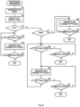
- FIG. 6 is a flowchart indicating voice signal transmission control processing of the control unit 30 (telephone relay unit 3, interface 3A). This processing indicates processing that is performed when the voice signal received from the telephone 20 or 22 is transmitted to a communication apparatus that is the communication partner.
- the control unit 30 refers to the PTT control table 38 (step S12).
- the PTT control table 38 is searched by using the apparatus type obtained by searching the call destination table 37 by using the identification number added to the INVITE message.
- the voice signal is transmitted using the retrieved control mode.
- step S13 If the determined control mode is the VOX mode (YES in step S13), the processing of steps S15 to S17 is executed. If the determined control mode is the DTFM mode (NO in step S13, YES in step S14), the processing of steps S20 to S24 is executed. If the determined control mode is the constant transmission mode (NO in step S13, NO in step S14), the processing of steps S25 and S26 is executed.
- the control unit 30 determines whether or not a voice signal whose level is the predetermined level or more is input (step S15), and only when a voice signal whose level is the predetermined level or more is input (YES in step S15), generates an RTP packet of the voice signal, and transmits the RTP packet (step S16).
- the processing described above is successively performed until the communication is ended (YES in step S17).
- the control unit 30 determines whether or not a PTT-ON instruction tone is input (step S20), and whether or not a PTT-OFF instruction tone is input (step S23), and generates and transmits RTP packets of the voice signal (step S22), in a period from when the PTT-ON instruction tone was input (YES in step S20) until when the PTT-OFF instruction tone is input (YES in step S23). Note that, if the communication is ended (YES in step S21 or S24) when monitoring the input of the PTT-ON instruction tone (step S20) and the input of the PTT-OFF instruction tone (step S23), the control unit 30 ends the processing.
- control unit 30 continues to generate and transmit RTP packets of the voice signal (step S25) until the communication is ended (YES in step S26).
- a voice RTP packet is generated and transmitted every fixed time period (every 20 ms, for example).
- the wireless communication relay unit 5 upon receiving a voice signal from the telephone relay unit 3 (via the network communication relay unit 4), performs control such that this voice signal is input to an apparatus (repeater or the like) that is connected to the external apparatus interface 34, and the voice signal is to be output. That is, when a repeater is connected, the wireless communication relay unit 5 instructs the repeater to transmit the voice signal by inputting a PTT signal. In the case of the microphone/speaker 29, the voice signal is output from the speaker as a sound without specific operation.
- the transmission control mode of the voice signal may be determined by searching the call destination table 37 and the PTT control table 38 based on the ID of the radio transceiver.
- the call destination table 37 is used as a table for determining the apparatus type of a communication apparatus that is the transmission source.
Landscapes
- Engineering & Computer Science (AREA)
- Multimedia (AREA)
- Computer Networks & Wireless Communication (AREA)
- Signal Processing (AREA)
- Business, Economics & Management (AREA)
- General Business, Economics & Management (AREA)
- Mobile Radio Communication Systems (AREA)
- Telephonic Communication Services (AREA)
Claims (10)
- Relaisvorrichtung (2), die eine Telefon-Relaiseinheit (3) und eine Drahtloskommunikations-Relaiseinheit (5) aufweist,wobei die Telefon-Relaiseinheit (3) Rufinformationen von einem Telefon (20, 22) über ein Netz (10) empfängt und, nachdem ein durch die Rufinformationen bezeichneter Kommunikationspartner geantwortet hat, ein Sprachsignal zu/von dem Telefon (20, 22) sendet/empfängt,die Drahtloskommunikations-Relaiseinheit (5), mit der ein Repeater (25, 27), der eine weitergebende Funkvorrichtung ist, verbunden ist, ein Sprachsignal über den Repeater (25, 27) zu/von einer Funkvorrichtung sendet/empfängt, die Telefon-Relaiseinheit (3) eine Zielvorrichtung, die eine zu rufende Funkvorrichtung ist, auf der Grundlage der von dem Telefon (20, 22) empfangenen Rufinformationen bestimmt und ein von dem Telefon (20, 22) empfangenes Sprachsignal an die Drahtloskommunikations-Relaiseinheit (5) überträgt,die Drahtloskommunikations-Relaiseinheit (5) ein von der Telefon-Relaiseinheit (3) übertragenes Sprachsignal an die Zielvorrichtung überträgt,die Telefon-Relaiseinheit (3) aufweist:eine Rufzieltabelle (37), in der für jede der Funkvorrichtungen eine Aufzeichnung gespeichert ist, die die Rufinformationen, eine Adresse der Zielvorrichtung und einen Vorrichtungstyp der Zielvorrichtung enthält; undeine Übertragungssteuertabelle, in der für jeden der Vorrichtungstypen eine Aufzeichnung gespeichert ist, die den Vorrichtungstyp und einen Übertragungssteuermodus eines Sprachsignals enthält; unddie Telefon-Relaiseinheit (3) den Vorrichtungstyp der Zielvorrichtung durch Bezugnahme auf die Rufzieltabelle (37) bestimmt, den Übertragungssteuermodus eines Sprachsignals, das dem bestimmten Vorrichtungstyp entspricht, durch Bezugnahme auf die Übertragungssteuertabelle bestimmt, und ein Sprachsignal an die Drahtloskommunikations-Relaiseinheit (5) unter Verwendung des bestimmten Modus überträgt.
- Relaisvorrichtung (2) nach Anspruch 1, wobei der Übertragungssteuermodus eines Sprachsignals einer ist von: einem Konstantübertragungsmodus, in dem Sprachsignale ohne Unterbrechung in einem Zeitraum übertragen werden, in dem das Telefon (20, 22) und die Zielvorrichtung eine Kommunikation durchführen, einem VOX-Modus, in dem das Sprachsignal nur dann übertragen wird, wenn ein Sprachsignal, dessen Pegel ein zuvor festgelegter Pegel oder mehr ist, von einem Telefon eingegeben wird, und einem DTFM-Modus, in dem Sprachsignale ohne Unterbrechung in einem Zeitraum ab dem Moment, an dem ein Tonsignal, das einen Sendebeginn anweist, eingegeben wurde, bis zu dem Moment, an dem ein Tonsignal, das einen Sendestopp anweist, eingegeben wird, übertragen werden.
- Relaisvorrichtung (2) nach Anspruch 2, wobei die Übertragungssteuertabelle einen Übertragungssteuermodus eines Sprachsignals gemäß einer Funktion des Sendens und Empfangens eines Sprachsignals, die die Zielvorrichtung aufweist, in Verknüpfung mit dem Vorrichtungstyp speichert.
- Relaisvorrichtung (2) nach Anspruch 2 oder 3, des Weiteren umfassend:
eine Netzkommunikations-Relaiseinheit (4), die:mit einem WLAN-Sender-Empfänger (23) zu verbinden ist, der ohne Durchführen eines vorherigen Ruf-Procederes ein Sprachsignal über das Netz (10) an einen Kommunikationspartner zu senden beginnt, undmit einem LTE-Sender-Empfänger (24) zu verbinden ist, der ohne Durchführen eines vorherigen Ruf-Procederes ein Sprachsignal über ein LTE-Netz (11), das ein Kommunikationsnetz eines Mobiltelefons ist, an einen Kommunikationspartner zu senden beginnt,wobei die Rufzieltabelle (37) und die Übertragungssteuertabelle für den WLAN-Sender-Empfänger (23) und den LTE-Sender-Empfänger (24) als Zielvorrichtungen die Rufinformationen, Adressen der Zielvorrichtungen, die Vorrichtungstypen und die Übertragungssteuermodi eines Sprachsignals speichern. - Relaisvorrichtung (2) nach einem der Ansprüche 2 bis 4, wobei die Rufzieltabelle (37) des Weiteren eine Aufzeichnung der Gruppenkommunikation speichert, in der mehrere Kommunikationsvorrichtungen Zielvorrichtungen sind.
- Verfahren zum Weitergeben eines Sprachsignals in einer Relaisvorrichtung (2), mit der ein Telefon (20, 22) und ein Repeater (25, 27), der eine weitergebende Funkvorrichtung ist, die mit einer Funkvorrichtung kommuniziert, verbunden sind, wobei das Relaisverfahren umfasst:Empfangen von Rufinformationen zum Rufen einer Funkvorrichtung von dem Telefon (20, 22);Bestimmen einer Zielvorrichtung, die eine zu rufende Funkvorrichtung ist, auf der Grundlage der Rufinformationen;Bestimmen eines Vorrichtungstyps der Zielvorrichtung durch Bezugnahme auf eine Rufzieltabelle (37), in der für jede der Funkvorrichtungen eine Aufzeichnung gespeichert ist, die die Rufinformationen, eine Adresse der Zielvorrichtung und einen Vorrichtungstyp der Zielvorrichtung enthält; undBestimmen eines Übertragungssteuermodus eines Sprachsignals, das dem bestimmten Vorrichtungstyp entspricht, durch Bezugnahme auf eine Übertragungssteuertabelle, in der für jeden der Vorrichtungstypen eine Aufzeichnung gespeichert ist, die den Vorrichtungstyp und den Übertragungssteuermodus eines Sprachsignals enthält;Rufen der Zielvorrichtung über den Repeater (25, 21); undÜbertragen, nachdem die Zielvorrichtung geantwortet hat, eines von dem Telefon (20, 22) empfangenen Sprachsignals an den Repeater (25, 27), unter Verwendung des bestimmten Übertragungssteuermodus.
- Verfahren zum Weitergeben eines Sprachsignals nach Anspruch 6,
wobei der Übertragungssteuermodus eines Sprachsignals einer ist von einem Konstantübertragungsmodus, in dem Sprachsignale ohne Unterbrechung in einem Zeitraum übertragen werden, in dem das Telefon (20, 22) und die Zielvorrichtung eine Kommunikation durchführen, einem VOX-Modus, in dem das Sprachsignal nur dann übertragen wird, wenn ein Sprachsignal, dessen Pegel ein zuvor festgelegter Pegel oder mehr ist, von dem Telefon (20, 22) eingegeben wird, und einem DTFM-Modus, in dem Sprachsignale ohne Unterbrechung in einem Zeitraum ab dem Moment, an dem ein Tonsignal, das einen Sendebeginn anweist, eingegeben wurde, bis zu dem Moment, an dem ein Tonsignal, das einen Sendestopp anweist, eingegeben wird, übertragen werden. - Verfahren zum Weitergeben eines Sprachsignals, wobei die Übertragungssteuertabelle einen Übertragungssteuermodus eines Sprachsignals gemäß einer Funktion des Sendens und Empfangens eines Sprachsignals, die die Zielvorrichtung hat, in Verknüpfung mit dem Vorrichtungstyp speichert.
- Verfahren zum Weitergeben eines Sprachsignals nach Anspruch 6,wobei die Weitergabevorrichtung (2) des Weiteren mit einem WLAN-Sender-Empfänger (23), der das Senden eines Sprachsignals an einen Kommunikationspartner ohne Durchführen eines vorherigen Ruf-Procederes beginnt, und einem LTE-Sender-Empfänger (24), der das Senden eines Sprachsignals an einen Kommunikationspartner ohne Durchführen eines vorherigen Ruf-Procederes beginnt, verbunden ist unddie Rufzieltabelle (37) und die Übertragungssteuertabelle die Rufinformationen, Adressen der Zielvorrichtungen, die Vorrichtungstypen, und die Übertragungssteuermodi eines Sprachsignals speichern, wobei der WLAN-Sender-Empfänger (23) und der LTE-Sender-Empfänger (24) Zielvorrichtungen sind.
- Verfahren zum Weitergeben eines Sprachsignals nach einem der Ansprüche 6 bis 9, wobei die Rufzieltabelle (37) des Weiteren eine Aufzeichnung der Gruppenkommunikation speichert, in der mehrere Kommunikationsvorrichtungen Zielvorrichtungen sind.
Applications Claiming Priority (2)
| Application Number | Priority Date | Filing Date | Title |
|---|---|---|---|
| JP2018181220A JP7168846B2 (ja) | 2018-09-27 | 2018-09-27 | 中継装置および音声信号の中継方法 |
| PCT/JP2019/017871 WO2020066106A1 (ja) | 2018-09-27 | 2019-04-26 | 中継装置および音声信号の中継方法 |
Publications (3)
| Publication Number | Publication Date |
|---|---|
| EP3843369A1 EP3843369A1 (de) | 2021-06-30 |
| EP3843369A4 EP3843369A4 (de) | 2022-05-18 |
| EP3843369B1 true EP3843369B1 (de) | 2025-06-04 |
Family
ID=69953052
Family Applications (1)
| Application Number | Title | Priority Date | Filing Date |
|---|---|---|---|
| EP19864264.7A Active EP3843369B1 (de) | 2018-09-27 | 2019-04-26 | Relaisvorrichtung und verfahren zur weiterleitung von sprachsignalen |
Country Status (5)
| Country | Link |
|---|---|
| US (1) | US11606404B2 (de) |
| EP (1) | EP3843369B1 (de) |
| JP (1) | JP7168846B2 (de) |
| CN (1) | CN112673613B (de) |
| WO (1) | WO2020066106A1 (de) |
Families Citing this family (2)
| Publication number | Priority date | Publication date | Assignee | Title |
|---|---|---|---|---|
| WO2020067848A1 (en) | 2018-09-28 | 2020-04-02 | Samsung Electronics Co., Ltd. | Positioning reference signal |
| JP7538412B2 (ja) | 2020-09-30 | 2024-08-22 | アイコム株式会社 | 無線システム、中継方法、および通信端末 |
Family Cites Families (13)
| Publication number | Priority date | Publication date | Assignee | Title |
|---|---|---|---|---|
| CN1656785B (zh) | 2002-05-31 | 2010-08-25 | 索福帮股份有限公司 | 终端连接装置及连接控制装置 |
| US7313103B2 (en) * | 2002-06-03 | 2007-12-25 | Motorola, Inc. | Method and apparatus for interactive communication between half-duplex and full-duplex systems |
| KR101067304B1 (ko) * | 2003-12-25 | 2011-09-23 | 오끼 덴끼 고오교 가부시끼가이샤 | 교환처리 시스템 |
| US8149743B1 (en) * | 2006-07-12 | 2012-04-03 | Nextel Communications Inc. | System and method for seamlessly switching a full-duplex session to a half-duplex session |
| US20150009865A1 (en) * | 2008-08-11 | 2015-01-08 | Qualcomm Incorporated | Server-initiated duplex transitions |
| JP5392003B2 (ja) * | 2009-03-30 | 2014-01-22 | 富士通株式会社 | 中継装置、状態通知方法、および、コンピュータプログラム |
| JP5392062B2 (ja) | 2009-12-24 | 2014-01-22 | アイコム株式会社 | 中継装置および通信システム |
| JP6098114B2 (ja) | 2012-10-26 | 2017-03-22 | アイコム株式会社 | 中継装置および通信システム |
| JP5966917B2 (ja) * | 2012-12-26 | 2016-08-10 | アイコム株式会社 | 中継装置 |
| JP5994630B2 (ja) | 2012-12-26 | 2016-09-21 | アイコム株式会社 | 中継装置 |
| US10194372B2 (en) | 2013-11-07 | 2019-01-29 | Icom Incorporated | Relaying device, audio-communication system and relaying method for relaying audio signal |
| JP6583270B2 (ja) | 2014-07-04 | 2019-10-02 | アイコム株式会社 | 中継装置、通信システムおよび音声信号の中継方法 |
| US11799922B2 (en) | 2016-12-21 | 2023-10-24 | T-Mobile Usa, Inc. | Network core facilitating terminal interoperation |
-
2018
- 2018-09-27 JP JP2018181220A patent/JP7168846B2/ja active Active
-
2019
- 2019-04-26 WO PCT/JP2019/017871 patent/WO2020066106A1/ja not_active Ceased
- 2019-04-26 CN CN201980059197.7A patent/CN112673613B/zh active Active
- 2019-04-26 US US17/273,054 patent/US11606404B2/en active Active
- 2019-04-26 EP EP19864264.7A patent/EP3843369B1/de active Active
Also Published As
| Publication number | Publication date |
|---|---|
| CN112673613A (zh) | 2021-04-16 |
| EP3843369A4 (de) | 2022-05-18 |
| CN112673613B (zh) | 2022-09-20 |
| WO2020066106A1 (ja) | 2020-04-02 |
| US11606404B2 (en) | 2023-03-14 |
| JP2020053837A (ja) | 2020-04-02 |
| EP3843369A1 (de) | 2021-06-30 |
| US20210329056A1 (en) | 2021-10-21 |
| JP7168846B2 (ja) | 2022-11-10 |
Similar Documents
| Publication | Publication Date | Title |
|---|---|---|
| CN1166242C (zh) | 使用短程通信控制链路在无线电话和有线电话之间的进行中的电话呼叫转移 | |
| US9924014B2 (en) | Cordless telephone equipment, cordless telephone system, and cordless telephone communication method | |
| US8019279B2 (en) | System and method for using mobile phones as handsets for IP softphones | |
| CN111867008B (zh) | 一种多模式基站及无绳通信系统 | |
| EP3843369B1 (de) | Relaisvorrichtung und verfahren zur weiterleitung von sprachsignalen | |
| EP3843370B1 (de) | Relaisvorrichtung und sprachkommunikationsaufzeichnungsverfahren | |
| CN1147326A (zh) | 处理呼叫冲突的方法 | |
| EP3843371B1 (de) | Relaisvorrichtung und sprachkommunikationsüberwachungsverfahren | |
| US10263665B2 (en) | Communication system | |
| KR100430614B1 (ko) | 블루투스 억세스 포인트를 이용한 사설 자동 교환망 시스템 | |
| HK40042183B (en) | Relay apparatus and method for relaying voice signal | |
| HK40042183A (en) | Relay apparatus and method for relaying voice signal | |
| JP3934138B2 (ja) | 通信システム | |
| JP4231755B2 (ja) | 翻訳通信システム及び通信端末装置 | |
| US20250184960A1 (en) | Systems and methods for peforming group paging of wireless terminals of a communication system | |
| JP6011793B2 (ja) | 中継装置および通信システム | |
| JP6537159B1 (ja) | 通信制御装置及び通信制御プログラム | |
| TW202527535A (zh) | 通訊格式調整方法 | |
| US8630254B2 (en) | Telephone line switching apparatus, telephone line switching system, telephone relay system, telephone relay method, telephone relay program | |
| JP2017022680A (ja) | 通信装置 | |
| JP5551493B2 (ja) | サービス制御装置、ガイダンス制御システム、及びガイダンス制御方法 | |
| JP2017022679A (ja) | 通信装置 | |
| JP2017060028A (ja) | 無線端末装置 | |
| JPH0282743A (ja) | 通信端末装置 | |
| JP2002374371A (ja) | 通話システム及び音声ゲートウェイ装置 |
Legal Events
| Date | Code | Title | Description |
|---|---|---|---|
| STAA | Information on the status of an ep patent application or granted ep patent |
Free format text: STATUS: THE INTERNATIONAL PUBLICATION HAS BEEN MADE |
|
| PUAI | Public reference made under article 153(3) epc to a published international application that has entered the european phase |
Free format text: ORIGINAL CODE: 0009012 |
|
| STAA | Information on the status of an ep patent application or granted ep patent |
Free format text: STATUS: REQUEST FOR EXAMINATION WAS MADE |
|
| 17P | Request for examination filed |
Effective date: 20210326 |
|
| AK | Designated contracting states |
Kind code of ref document: A1 Designated state(s): AL AT BE BG CH CY CZ DE DK EE ES FI FR GB GR HR HU IE IS IT LI LT LU LV MC MK MT NL NO PL PT RO RS SE SI SK SM TR |
|
| DAV | Request for validation of the european patent (deleted) | ||
| DAX | Request for extension of the european patent (deleted) | ||
| REG | Reference to a national code |
Ref country code: DE Ref legal event code: R079 Free format text: PREVIOUS MAIN CLASS: H04M0003000000 Ipc: H04W0004180000 Ref document number: 602019070882 Country of ref document: DE |
|
| A4 | Supplementary search report drawn up and despatched |
Effective date: 20220414 |
|
| RIC1 | Information provided on ipc code assigned before grant |
Ipc: H04M 3/42 20060101ALI20220408BHEP Ipc: H04M 3/00 20060101ALI20220408BHEP Ipc: H04W 4/18 20090101AFI20220408BHEP |
|
| GRAP | Despatch of communication of intention to grant a patent |
Free format text: ORIGINAL CODE: EPIDOSNIGR1 |
|
| STAA | Information on the status of an ep patent application or granted ep patent |
Free format text: STATUS: GRANT OF PATENT IS INTENDED |
|
| INTG | Intention to grant announced |
Effective date: 20250304 |
|
| GRAS | Grant fee paid |
Free format text: ORIGINAL CODE: EPIDOSNIGR3 |
|
| GRAA | (expected) grant |
Free format text: ORIGINAL CODE: 0009210 |
|
| STAA | Information on the status of an ep patent application or granted ep patent |
Free format text: STATUS: THE PATENT HAS BEEN GRANTED |
|
| AK | Designated contracting states |
Kind code of ref document: B1 Designated state(s): AL AT BE BG CH CY CZ DE DK EE ES FI FR GB GR HR HU IE IS IT LI LT LU LV MC MK MT NL NO PL PT RO RS SE SI SK SM TR |
|
| REG | Reference to a national code |
Ref country code: GB Ref legal event code: FG4D |
|
| REG | Reference to a national code |
Ref country code: CH Ref legal event code: EP |
|
| REG | Reference to a national code |
Ref country code: DE Ref legal event code: R096 Ref document number: 602019070882 Country of ref document: DE |
|
| REG | Reference to a national code |
Ref country code: IE Ref legal event code: FG4D |
|
| REG | Reference to a national code |
Ref country code: NL Ref legal event code: MP Effective date: 20250604 |
|
| PG25 | Lapsed in a contracting state [announced via postgrant information from national office to epo] |
Ref country code: FI Free format text: LAPSE BECAUSE OF FAILURE TO SUBMIT A TRANSLATION OF THE DESCRIPTION OR TO PAY THE FEE WITHIN THE PRESCRIBED TIME-LIMIT Effective date: 20250604 Ref country code: ES Free format text: LAPSE BECAUSE OF FAILURE TO SUBMIT A TRANSLATION OF THE DESCRIPTION OR TO PAY THE FEE WITHIN THE PRESCRIBED TIME-LIMIT Effective date: 20250604 |
|
| REG | Reference to a national code |
Ref country code: LT Ref legal event code: MG9D |
|
| PG25 | Lapsed in a contracting state [announced via postgrant information from national office to epo] |
Ref country code: GR Free format text: LAPSE BECAUSE OF FAILURE TO SUBMIT A TRANSLATION OF THE DESCRIPTION OR TO PAY THE FEE WITHIN THE PRESCRIBED TIME-LIMIT Effective date: 20250905 Ref country code: NO Free format text: LAPSE BECAUSE OF FAILURE TO SUBMIT A TRANSLATION OF THE DESCRIPTION OR TO PAY THE FEE WITHIN THE PRESCRIBED TIME-LIMIT Effective date: 20250904 |
|
| PG25 | Lapsed in a contracting state [announced via postgrant information from national office to epo] |
Ref country code: PL Free format text: LAPSE BECAUSE OF FAILURE TO SUBMIT A TRANSLATION OF THE DESCRIPTION OR TO PAY THE FEE WITHIN THE PRESCRIBED TIME-LIMIT Effective date: 20250604 |
|
| PG25 | Lapsed in a contracting state [announced via postgrant information from national office to epo] |
Ref country code: BG Free format text: LAPSE BECAUSE OF FAILURE TO SUBMIT A TRANSLATION OF THE DESCRIPTION OR TO PAY THE FEE WITHIN THE PRESCRIBED TIME-LIMIT Effective date: 20250604 |
|
| PG25 | Lapsed in a contracting state [announced via postgrant information from national office to epo] |
Ref country code: HR Free format text: LAPSE BECAUSE OF FAILURE TO SUBMIT A TRANSLATION OF THE DESCRIPTION OR TO PAY THE FEE WITHIN THE PRESCRIBED TIME-LIMIT Effective date: 20250604 |
|
| PG25 | Lapsed in a contracting state [announced via postgrant information from national office to epo] |
Ref country code: RS Free format text: LAPSE BECAUSE OF FAILURE TO SUBMIT A TRANSLATION OF THE DESCRIPTION OR TO PAY THE FEE WITHIN THE PRESCRIBED TIME-LIMIT Effective date: 20250904 |
|
| PG25 | Lapsed in a contracting state [announced via postgrant information from national office to epo] |
Ref country code: LV Free format text: LAPSE BECAUSE OF FAILURE TO SUBMIT A TRANSLATION OF THE DESCRIPTION OR TO PAY THE FEE WITHIN THE PRESCRIBED TIME-LIMIT Effective date: 20250604 |
|
| PG25 | Lapsed in a contracting state [announced via postgrant information from national office to epo] |
Ref country code: NL Free format text: LAPSE BECAUSE OF FAILURE TO SUBMIT A TRANSLATION OF THE DESCRIPTION OR TO PAY THE FEE WITHIN THE PRESCRIBED TIME-LIMIT Effective date: 20250604 |
|
| PG25 | Lapsed in a contracting state [announced via postgrant information from national office to epo] |
Ref country code: PT Free format text: LAPSE BECAUSE OF FAILURE TO SUBMIT A TRANSLATION OF THE DESCRIPTION OR TO PAY THE FEE WITHIN THE PRESCRIBED TIME-LIMIT Effective date: 20251006 |
|
| REG | Reference to a national code |
Ref country code: AT Ref legal event code: MK05 Ref document number: 1801530 Country of ref document: AT Kind code of ref document: T Effective date: 20250604 |
|
| PG25 | Lapsed in a contracting state [announced via postgrant information from national office to epo] |
Ref country code: IS Free format text: LAPSE BECAUSE OF FAILURE TO SUBMIT A TRANSLATION OF THE DESCRIPTION OR TO PAY THE FEE WITHIN THE PRESCRIBED TIME-LIMIT Effective date: 20251004 |
|
| PG25 | Lapsed in a contracting state [announced via postgrant information from national office to epo] |
Ref country code: AT Free format text: LAPSE BECAUSE OF FAILURE TO SUBMIT A TRANSLATION OF THE DESCRIPTION OR TO PAY THE FEE WITHIN THE PRESCRIBED TIME-LIMIT Effective date: 20250604 Ref country code: SM Free format text: LAPSE BECAUSE OF FAILURE TO SUBMIT A TRANSLATION OF THE DESCRIPTION OR TO PAY THE FEE WITHIN THE PRESCRIBED TIME-LIMIT Effective date: 20250604 |
|
| PG25 | Lapsed in a contracting state [announced via postgrant information from national office to epo] |
Ref country code: CZ Free format text: LAPSE BECAUSE OF FAILURE TO SUBMIT A TRANSLATION OF THE DESCRIPTION OR TO PAY THE FEE WITHIN THE PRESCRIBED TIME-LIMIT Effective date: 20250604 |
|
| PG25 | Lapsed in a contracting state [announced via postgrant information from national office to epo] |
Ref country code: EE Free format text: LAPSE BECAUSE OF FAILURE TO SUBMIT A TRANSLATION OF THE DESCRIPTION OR TO PAY THE FEE WITHIN THE PRESCRIBED TIME-LIMIT Effective date: 20250604 |
|
| PG25 | Lapsed in a contracting state [announced via postgrant information from national office to epo] |
Ref country code: SK Free format text: LAPSE BECAUSE OF FAILURE TO SUBMIT A TRANSLATION OF THE DESCRIPTION OR TO PAY THE FEE WITHIN THE PRESCRIBED TIME-LIMIT Effective date: 20250604 Ref country code: RO Free format text: LAPSE BECAUSE OF FAILURE TO SUBMIT A TRANSLATION OF THE DESCRIPTION OR TO PAY THE FEE WITHIN THE PRESCRIBED TIME-LIMIT Effective date: 20250604 |
|
| PG25 | Lapsed in a contracting state [announced via postgrant information from national office to epo] |
Ref country code: IT Free format text: LAPSE BECAUSE OF FAILURE TO SUBMIT A TRANSLATION OF THE DESCRIPTION OR TO PAY THE FEE WITHIN THE PRESCRIBED TIME-LIMIT Effective date: 20250604 |