EP3839259B1 - Pumpe für mit feststoff belastete flüssigkeit - Google Patents
Pumpe für mit feststoff belastete flüssigkeit Download PDFInfo
- Publication number
- EP3839259B1 EP3839259B1 EP20210961.7A EP20210961A EP3839259B1 EP 3839259 B1 EP3839259 B1 EP 3839259B1 EP 20210961 A EP20210961 A EP 20210961A EP 3839259 B1 EP3839259 B1 EP 3839259B1
- Authority
- EP
- European Patent Office
- Prior art keywords
- cutting
- pump
- housing
- cutting body
- motor shaft
- Prior art date
- Legal status (The legal status is an assumption and is not a legal conclusion. Google has not performed a legal analysis and makes no representation as to the accuracy of the status listed.)
- Active
Links
Images


Classifications
-
- F—MECHANICAL ENGINEERING; LIGHTING; HEATING; WEAPONS; BLASTING
- F04—POSITIVE - DISPLACEMENT MACHINES FOR LIQUIDS; PUMPS FOR LIQUIDS OR ELASTIC FLUIDS
- F04D—NON-POSITIVE-DISPLACEMENT PUMPS
- F04D7/00—Pumps adapted for handling specific fluids, e.g. by selection of specific materials for pumps or pump parts
- F04D7/02—Pumps adapted for handling specific fluids, e.g. by selection of specific materials for pumps or pump parts of centrifugal type
- F04D7/04—Pumps adapted for handling specific fluids, e.g. by selection of specific materials for pumps or pump parts of centrifugal type the fluids being viscous or non-homogenous
- F04D7/045—Pumps adapted for handling specific fluids, e.g. by selection of specific materials for pumps or pump parts of centrifugal type the fluids being viscous or non-homogenous with means for comminuting, mixing stirring or otherwise treating
-
- F—MECHANICAL ENGINEERING; LIGHTING; HEATING; WEAPONS; BLASTING
- F04—POSITIVE - DISPLACEMENT MACHINES FOR LIQUIDS; PUMPS FOR LIQUIDS OR ELASTIC FLUIDS
- F04D—NON-POSITIVE-DISPLACEMENT PUMPS
- F04D29/00—Details, component parts, or accessories
- F04D29/18—Rotors
- F04D29/22—Rotors specially for centrifugal pumps
- F04D29/2261—Rotors specially for centrifugal pumps with special measures
- F04D29/2288—Rotors specially for centrifugal pumps with special measures for comminuting, mixing or separating
Definitions
- the invention relates to a pump for liquids laden with solids, with a pump housing and a cutting mechanism provided on a base plate of the pump housing in a suction area, the pump housing having an axially extending rotatable motor shaft and an impeller non-rotatably fixed to the motor shaft.
- Admixtures of solids in liquids such as waste water can clog pumps or pipes.
- cutters are used, which are located in front of a suction area of the pump, in order to comminute the solids contained in the liquid.
- Cutting units known from the prior art see e.g. B. DE 10 2008 057233 A1 and WO 2006/058605 A1 , often have a fixed part, called the cutting surface or cutting element, and a rotating part, called the cutting body.
- the cutting surfaces also known as the cutting sieve, have openings through which the liquid flows to an impeller of the pump. If the cutting surface is flat or conical, it is referred to as a cutting insert.
- a cylindrical shape of the cutting surface is called a cutting ring.
- a cutting unit upstream of the pump has an effect due to the influence on the inflow into the pump, it usually has a negative effect on the efficiency and the characteristic curve of the pump.
- the rotating cutting body is located almost exclusively within a pump chamber of the pump, a part of the cutting body, the cutting element, but at least partially protrudes beyond the base plate and in particular penetrates in this way.
- the rotating cutting body also known as the cutting head, is thus essentially located within the pump chamber, but the actual cutting edge for comminuting the solid is located at least partially outside the pump chamber.
- the cutting mechanism or the cutting edges preferably have a radial and/or axial component, which leads to better comminution of the solid and thus to improved operational reliability of the pump.
- the proposed outwardly drawn cutting elements prevent solids from getting stuck in front of the cutter.
- the external cutting edges also act as a vortex device, so that the solids in the suction area of the pump remain constantly in motion.
- Torque is preferably transmitted to the rotating part of the cutting unit via a cover disk and enables an unobstructed and therefore streamlined design of a suction mouth of the pump in the impeller.
- the proposed 'external chopping' is achieved in particular by the fact that the cutting element and cutting body, in particular the cutting edge, do not form a continuous shape known from the prior art, such as a plane, cylinder or cone, but rather have a discontinuity in that they flow out of the pump chamber at least to the almost sticking out.
- the proposed solution allows the above-described functional separation of the cutting gap and the impeller sealing gap mechanically independently of one another without blocking the suction mouth of the impeller.
- the cutting edge preferably completely protrudes at least partially over the base plate in the first rotation sector
- the cutting body which can be rotated by the motor shaft, can also cut the solid, for example a piece of textile in its extent greater than the suction area, in the first rotation sector of the rotatable cutting edge.
- no cutting element is preferably provided in the first rotation sector. The rotational movement of the motor shaft moves the textile gripped by the cutting edge of the cutting body towards the cutting edge of the cutting element and in this way gets between the engaging cutting edges, so that the textile is shredded by the cutting edges.
- the first rotation sector can each cover about 160°, for example, while the second rotation sector, which is preferably formed by a flat extension of the cutting element in the radial direction, can each be about 20°.
- the cutting element is preferably fastened to the base plate on its transverse sides.
- the first and second sectors of rotation preferably do not overlap and/or preferably directly adjoin one another.
- Cutting element-free means that there is no cutting element in the first rotation sector or the cutting element does not protrude beyond the cutting body, so that the solid can be grasped particularly easily by the cutting edge.
- the base plate can, for example, be ring-shaped and/or frame the cutting body.
- a pump is generally referred to as a fluid machine that uses a rotary movement and dynamic forces to convey liquids as the medium.
- the pump is preferably designed as a centrifugal pump.
- the medium, centrifugal force occurring in radial flow is used for delivery, so that such pumps are also referred to as centrifugal pumps.
- the pump can preferably be used for a hydraulic system in a building, for example as a waste water pump.
- the liquid preferably includes waste water.
- the solid contained in the liquid can contain impurities of any kind, for example dirt, wood, undergrowth, textiles, rags or the like.
- the proposed pump is also for heating with radiators, radiator heating, underfloor heating, ceiling heating, a fan-assisted water/air heat exchanger for heating in the room, a fan convector for heating, a heating system with a hydraulic separator, a heating system with a heat exchanger, and ceiling cooling , underfloor cooling, a fan-assisted water/air heat exchanger for cooling in the room, a fan convector for cooling, a cooling system with a hydraulic separator, a cooling system with a heat exchanger, a hot water circulation system in a drinking water system or a drinking water system with a storage charging system, the above list not being exhaustive, but other types of systems not mentioned here can also be included.
- the cutting unit preferably serves as a chopper to crush and/or chop the solids contained in the liquid, so that the intake area is not clogged and the liquid with the crushed solids can be conveyed through the impeller without any problems.
- the liquid sucked in by the pump first passes through the cutting unit in the intake area before it reaches the running gear.
- the pump preferably has a motor which drives the motor shaft and thus the impeller.
- a computerized controller is also preferably provided, which controls the motor, for example with regard to its speed.
- the base plate can be part of the pump housing, in particular it can be designed in one piece or separately from it.
- Extending axially means in particular, for example, that the cutting element extends axially at least in the area of the base plate this is arranged at a distance from the impeller, and is thus arranged in particular outside of a pump chamber of the pump.
- Grasping the material to be cut means, for example, that the solid material is rotated along with it by the rotating cutting edge of the cutting body and is moved towards the cutting edge of the cutting element.
- the base plate can be made of glass fiber reinforced plastic, in particular glass fiber reinforced polypropylene.
- the base plate can also be made of gray cast iron, investment casting or polyurethane, which also applies to the pump housing, the cutting unit and/or the impeller.
- the cutting body is preferably mechanically connected to the motor wool, preferably screwed, riveted and/or connected to it by a fastener.
- the cutting body is particularly preferably arranged on the impeller, in particular screwed, riveted and/or connected to it by a fastening means.
- Extending radially and/or axially means that the cutting edge extends at least partially radially and/or axially, but not that the cutting edge extends, for example as a cone, only at an angle greater than zero to the radial and/or axial.
- the cutting element and the cutting body each have an at least radially extending cutting edge for comminuting the solid.
- the cutting edge preferably tapers in a wedge shape and/or is pointed.
- the cutting edge extends radially and/or axially
- the cutting element and the cutting body each have a further axially and/or radially extending cutting edge and/or the cutting element and the cutting body each have one radially and two axially extending cutting edges up.
- at least one further axially or radially extending cutting edge is thus provided, as a result of which more effective comminution of the solid is achieved.
- the cutting element and the cutting body have a plurality of cutting edges provided at regular intervals.
- the solid can be comminuted much more efficiently. 2, 3, 4 or 5 cutting edges are preferably provided.
- the cutting element has two radially extending cutting edges and the cutting body has three radially extending cutting edges.
- Such a configuration has proven to be particularly effective and can also be manufactured more easily by the cutting element being designed, for example, like a bow, which is applied to the pump housing or the base plate.
- the cutting edges are preferably provided at regular intervals, so that a balance-free rotation of the cutting body is possible.
- the cutting body is disk-shaped and/or hub-shaped and/or the cutting body is mounted on the cutting element at its edge and/or at its axis.
- the cutting body is preferably mounted at its edge and/or at its axis by means of a bearing on the cutting element.
- Cutting body and cutting element are preferably made of metal.
- the cutting body has a radially extending cutting body opening downstream of the cutting edge in the direction of rotation of the motor shaft, for the liquid to flow through the cutting body to the impeller.
- the cutter body opening preferably extends between the edge and the axis of the cutter body.
- the cutting body is preferably designed to be closed between the cutting body openings.
- An edge of the cutting body opening, in the axial direction, is preferably designed to be congruent with a radially extending cutting edge.
- the cutting body has a cutting housing extending axially away from the base plate, on which the cutting edge is provided in the direction of rotation of the motor shaft and through which between a side of the cutting housing assigned to the cutting edge and a cutting body opening a flow channel is formed for the flow of the liquid through the cutting body to the impeller.
- the flow channel between the cutting body opening and the side of the cutting housing assigned to the cutting edge is preferably of closed design.
- the cutting housing preferably extends on the side of the cutting body facing away from the impeller away from this 'quasi' out of the pump chamber, so that the cutting edge projects out of the pump chamber and/or protrudes beyond the base plate.
- the cutting housing supports the conveying effect of the pump like a paddle wheel.
- the cutting housing achieves a discontinuity known from the prior art, since no continuous shape such as a plane, cylinder or cone is used, which leads to the above-described improved comminution with simultaneously improved efficiency.
- the particularly open side of the cutter housing associated with the cutting edge is designed as a cutter housing opening extending in the axial direction and/or the flow channel extends at an angle of ⁇ 20° and ⁇ 70° to the axial extension of the motor shaft.
- the cutter housing opening is preferably open only in the axial direction.
- the flow channel preferably extends at an angle of ⁇ 30° and ⁇ 60°, preferably ⁇ 40° and ⁇ 50° to the axial extent of the motor shaft. In this way, the flow channel is inclined relative to the radial line, so that the liquid can flow through the flow channel with less flow resistance.
- the cutting housing is triangular or box-shaped in relation to the axial extension of the motor shaft.
- a triangular design that is ergonomic in this way improves the efficiency and the characteristic curve while at the same time having a high crushing capacity of the pump.
- the cutting body opening has a bevel formed in front of the cutting housing in the direction of rotation of the motor shaft and in the cutting body.
- the bevel can be produced as a milling and facilitates the flow of the liquid through the cutting body opening towards the impeller.
- the cutting element has a U-shaped bracket which extends axially away from the base plate and on which the cutting edge is provided.
- Each cutting edge is preferably assigned a bracket.
- two cutting edges can be arranged opposite one another on a single bracket, with the common bracket spanning the cutting body.
- the cutting edges are designed to be congruent and/or form-fitting to one another. A particularly good comminution of the solid can be achieved in this way.
- Both radial and axial parts of the cutting edges are preferably designed to be congruent and/or form-fitting to one another.
- Particularly preferably, radial and/or axial parts of the cutting edges and the cutting body and the cutting element slide past one another directly when the cutting body rotates, without touching one another.
- a gap between the radial and/or axial parts of the cutting edges of the cutting edges and the cutting body is preferably 0.1 mm, 0.2 mm, 0.5 mm, 1 mm or 2 mm or is less than or equal to the aforementioned values.
- the pump has a shaft sealing ring and/or a split ring for sealing a hydraulic gap between the impeller and the pump housing.
- the shaft sealing ring preferably has a sealing lip which rests on the impeller and is preferably pressed radially onto the impeller by a tubular spring and/or garter spring.
- the shaft sealing ring can be introduced with a firm seat in the pump housing and/or is preferably designed as a radial shaft sealing ring.
- a V-ring seal preferably made of nitrile rubber, can also be provided.
- the impeller is closed or open.
- a closed carriage makes it possible to carry out the cutting gap independently of the hydraulic gap, which in this respect is particularly advantageous and enables simple manufacture.
- the proposed pump can also be designed with an open impeller, in which case the connection can be made via the impeller hub.
- the impeller can also be designed as a semi-open multi-channel impeller.
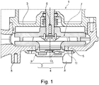
- the pump 1 shows a schematic cross section of a part of a pump 1 with a cutting unit 2 according to a preferred embodiment of the invention.
- the pump 1 is part of a hydraulic system of a building, not shown, and can be used in the field of heating, refrigeration and air conditioning technology, water supply and particularly advantageously in waste water disposal and purification.
- the pump 1 is used to convey liquid loaded with solids in the sewage disposal.
- the pump 1 has a pump housing 3 on the underside of which a circular, ring-like base plate 5 is provided in an intake area 4 .
- the cutting unit 2 is provided on the base plate 5 in the intake area 4 .
- the pump housing 3 also has an axially extending motor shaft 6 and an impeller 7 which is fixed in a rotationally fixed manner on the motor shaft 6 and which in the present case is of closed design.
- a plurality of supporting feet 8 grouped around the intake area 4 are also provided on the pump housing 3 outside the base plate 5 .
- the cutting mechanism 2 has on the one hand a cutting element 9 provided in a stationary manner on the base plate 5 and a cutting body 10 fixed in a rotationally fixed manner on the motor shaft 6 .
- the cutting body 10 is non-rotatably attached to the impeller 7 by means of a screw connection (not shown) and can therefore be rotated by the motor shaft 7, while the cutting element 9 is fixed in place on the base plate 5 by means of a screw connection (also not shown).
- a shaft sealing ring 11 or, alternatively, a circumferential split ring is provided to seal a hydraulic gap between the impeller 7 and the pump housing 5.
- the cutting element 9 and the cutting body 10 each have a plurality of radially and/or axially extending cutting edges 12 that project axially beyond the base plate 5 and interact with one another for crushing the solid.
- the cutting edge 12 of the cutting body 10 protrudes at least partially axially over the base plate 5 in order to Cutting body 10 to first detect the solid.
- the cutting element 9 protrude axially beyond the cutting body 10 in such a way that the cutting edges 12 can interact to comminute the solid matter that has been seized.
- the cutter body is 10 in 2 has three cutting edges 12 arranged opposite one another around the central axis of the motor shaft 6, each of the three first sectors of rotation extends over approximately 100°, so that each of the three second sectors of rotation extends over approximately 20°.
- the cutting element 9 has three U-shaped brackets 13 extending axially away from the base plate 5, which are arranged at regular intervals in the intake area 4 and on which the cutting edges 12 are each provided on a side facing the motor shaft in the direction of rotation.
- the cutting element 9 has a collar-like, circular edge which is in contact with the base plate 5 .
- the brackets 13 connect the edge with a circular central part, so that 13 recesses are provided between the brackets.
- the brackets each have two transverse sides, which extend perpendicularly away from the edge or the central part, and a longitudinal side, which extends between the transverse sides, perpendicular to these and the base plate 5 and projecting axially over them.
- the transverse sides measure 3 to 4 cm, for example, while the long side extends over 5 to 20 cm, for example.
- Both transverse sides and the longitudinal side are each provided with cutting edges 12 on their side facing the motor shaft in the direction of rotation.
- the cutting body 10 is disk-shaped and/or hub-shaped.
- the cutting body 10 is rotatably mounted on the cutting element 9 at its edge and at its axis.
- a bearing can be provided in each case for storage.
- the cutter body 10 has two box-like cutter housings 14 which extend axially away from the base plate 5 and are arranged at regular intervals and in such an opposite manner in the suction area 4 .
- a rectangular cutter housing opening 15 extending in the axial direction is formed on each cutter housing 14 in the direction of rotation of the motor shaft 6 .
- Radially or axially extending cutting edges 12 are provided on both transverse sides and on the longitudinal side of the cutter housing opening 15 facing away from the base plate 5 .
- a radially extending cutting body opening 16 through which the liquid can flow through the cutting body 10 to the impeller 7 , is formed in the cutting body 10 , virtually concealed by the cutting housing 14 in the axial direction of view of the cutting body 10 . Since the cutter housing 14 is otherwise closed, a flow channel 17 is formed through the cutter housing 14 between the rectangular cutter housing opening 15 and the rectangular cutter body opening 16 through which the liquid can flow.
- the cutting edges 12 of the cutting body 10 are as in 2 shown on the right on the left-hand cutting housing 14 in a form-fitting or congruent manner with the cutting edges 12 of the cutting element 9, so that the cutting housings 14, if the cutting body 10 is rotated by the motor shaft 6, can slide precisely through the brackets 14 with their cutting edges 12 first and can comminute solids in the liquid in this way between the cutting edges 12 .
- the pump 1 differs according to 3 in the configuration of the cutting housing 14, which is triangular in relation to the axial extension of the motor shaft 6.
- the flow channel 17 extends at an angle of approximately 30° to the axial extent of the motor shaft 6.
- the cutting body opening 16 has a bevel 18 which is located in front of the cutting housing 15 in the direction of rotation of the motor shaft 6 and is formed in the cutting body 10, through which a larger volume of liquid can flow into the pump 1 given the triangular design of the cutting housing 14.
- FIG. 1 shows a perspective view from below of a cutting element 9 of the cutting mechanism 6 according to FIG 4 according to the further preferred embodiment of the invention.
- a radially outer axial cutting edge 12 and a radial cutting edge 12 are provided, but not a radially inner axial cutting edge 12.
- the bracket 13 is designed as a one-piece bracket 13 which, as in FIG 4 to recognize, the cutting body 10 spans, wherein the cutting body 10 is mounted in the middle and at the ends of the bracket 13 on the cutting element 9.
Landscapes
- Engineering & Computer Science (AREA)
- Mechanical Engineering (AREA)
- General Engineering & Computer Science (AREA)
- Structures Of Non-Positive Displacement Pumps (AREA)
Description
- Die Erfindung betrifft eine Pumpe für mit Feststoff belastete Flüssigkeit, mit einem Pumpengehäuse und einem an einer Bodenplatte des Pumpengehäuses in einem Ansaugbereich vorgesehenen Schneidwerk, wobei das Pumpengehäuse eine sich axial erstreckende rotierbare Motorwelle und ein an der Motorwelle drehfest befestigtes Laufrad aufweist.
- Beimengungen von Feststoffen in Flüssigkeiten wie Abwasser können Pumpen oder Rohrleitungen verstopfen. Um solche Verstopfungen zu verhindern, werden Schneidwerke eingesetzt, welche sich vor einem Ansaugbereich der Pumpen befinden, um die in der Flüssigkeit enthaltenen Feststoffe zu zerkleinern.
- Aus dem Stand der Technik bekannte Schneidwerke, siehe z. B.
DE 10 2008 057233 A1 undWO 2006/058605 A1 , weisen oftmals einen feststehenden Teil, Schneidfläche oder Schneidelement genannt, und einem rotierenden Teil auf, Schneidkörper genannt. Je nach Einsatzgebiet des Schneidwerks können kreisförmige, kegelförmige oder zylindrische Schneidflächen eingesetzt werden. Die Schneidflächen, auch Schneidsieb genannt, weisen Öffnungen auf, durch die die Flüssigkeit hin zu einem Laufrad der Pumpe strömt. Bei ebener oder kegelförmiger Ausprägung der Schneidfläche spricht man von einer Schneidplatte. Eine zylindrische Ausprägung der Schneidfläche wird als Schneidring bezeichnet. - Während die Schneidwirkung solche Schneidwerke jedenfalls im Neuzustand gut ist, können die Schneidwerke selbst verstopfen, durch die Feststoffe blockiert werden oder es können sich Feststoffe vor dem Ansaugbereich der Pumpe festsetzen und dadurch den Ansaugbereich verschließen. Zudem wirkt sich ein der Pumpe vorgeschaltete Schneidwerk aufgrund der Beeinflussung der Zuströmung in die Pumpe in der Regel negativ auf den Wirkungsgrad und die Kennlinie der Pumpe aus.
- Ausgehend von dieser Situation ist es eine Aufgabe der vorliegenden Erfindung, eine Pumpe mit einem Schneidwerk bereitzustellen, welches gegenüber den aus dem Stand der Technik bekannten Lösungen betriebssicherer ist und zugleich einen hohen hydraulischen Wirkungsgrad der Pumpe ermöglicht.
- Die Aufgabe der Erfindung wird durch die Merkmale des unabhängigen Anspruchs gelöst. Vorteilhafte Ausgestaltungen sind in den Unteransprüchen angegeben.
- Demnach wird die Aufgabe gelöst durch eine Pumpe für mit Feststoff belastete Flüssigkeit, mit
- einem Pumpengehäuse, einer sich axial erstreckenden rotierbaren Motorwelle mit daran drehfest befestigtem Laufrad und einem an einer Bodenplatte des Pumpengehäuses in einem Ansaugbereich vorgesehenen Schneidwerk, wobei
- das Schneidwerk ein an der Bodenplatte stationär vorgesehenes Schneidelement und einen drehfest an der Motorwelle befestigten rotierbare Schneidkörper mit jeweiliger Schneidkante aufweist,
- die Schneidkante des Schneidkörpers in einem ersten Schneidelement-freien Rotationssektor des Schneidkörpers die Bodenplatte zum Erfassen des Feststoffes wenigstens zum Teil axial überragt, und
- das Schneidelement den Schneidkörper nur in einem von dem ersten Rotationssektor verschiedenen zweiten Rotationssektor des Schneidkörpers axial überragt, so dass die Schneidkanten zum Zerkleinern des erfassten Feststoffes zusammenwirken können.
- Die Aufgabe wird ferner gelöst durch eine Pumpe für mit Feststoff belastete Flüssigkeit, mit
- einem Pumpengehäuse und einem an einer Bodenplatte des Pumpengehäuses in einem Ansaugbereich vorgesehenen Schneidwerk, wobei
- das Pumpengehäuse eine sich axial erstreckende Motorwelle und ein an der Motorwelle drehfest befestigtes Laufrad aufweist,
- das Schneidwerk ein an der Bodenplatte stationär vorgesehenes Schneidelement und einen drehfest an der Motorwelle befestigten Schneidkörper aufweist, und
- das Schneidelement und der Schneidkörper jeweils eine sich radial und/oder axial erstreckende, die Bodenplatte axial überragende und miteinander zusammenwirkende Schneidkante zum Zerkleinern des Feststoffes aufweisen.
- Ein wesentlicher Aspekt der Erfindung liegt darin, dass der rotierende Schneidkörper fast ausschließlich innerhalb eines Pumpenraumes der Pumpe liegt, ein Teil des Schneidkörpers, das Schneidelement, jedoch die Bodenplatte wenigstens zum Teil überragt und derart insbesondere durchdringt. Der rotierende Schneidkörper, auch Schneidkopf benannt, findet sich somit im Wesentlichen innerhalb des Pumpenraumes, die eigentliche Schneidkante zum Zerkleinern des Feststoffes befindet sich jedoch quasi wenigstens zum Teil außerhalb des Pumpenraumes. Das Schneidwerk beziehungsweise die Schneidkanten haben bevorzugt eine radiale und/oder axiale Komponente, was zu einer besseren Zerkleinerung des Feststoffes und derart zu einer verbesserten Betriebssicherheit der Pumpe führt.
- Im Gegensatz zu rein innenliegenden aus dem Stand der Technik bekannten Schneidwerken wird mit Hilfe der vorgeschlagenen nach außen gezogenen Schneidelemente verhindert, dass sich Feststoffe vor dem Schneidwerk festsetzen. Die außenliegenden Schneidkanten wirken im Betrieb der Pumpe gleichzeitig als Wirbeleinrichtung, sodass die Feststoffe im Ansaugbereich der Pumpe stetig in Bewegung bleiben. Zudem besteht eine funktionale Trennung zwischen einem radialen Spalt des rotierenden Schneidkörpers und des feststehenden Schneidelementes und einem hydraulischen Spalt zwischen Laufrad und Pumpengehäuse. Diese funktionale Trennung resultiert in einer Verbesserung eines hydraulischen Wirkungsgrades des Laufrades unter Verwendung des geeigneten hydraulischen Spaltes und des unabhängig davon wirkenden radialen Spaltes des Schneidwerkers.
- Eine Momentübertragung auf den rotierenden Teil des Schneidwerkes erfolgt bevorzugt über eine Deckscheibe und ermöglicht eine unversperrte und damit strömungsgünstige Ausprägung eines Saugmundes der Pumpe im Laufrad. Die vorgeschlagene ,externe Häckselung' wird insbesondere dadurch erreicht, dass Schneidelement und Schneidkörper, insbesondere die Schneidkante, keine stetige aus dem Stand der Technik bekannte Form wie beispielsweise Ebene, Zylinder oder Kegel bilden, sondern eine Unstetigkeit aufweisen, indem sie aus dem Pumpenraum jedenfalls zum Teil quasi herausragen. Zudem erlaubt die vorgeschlagene Lösung die zuvor beschriebene funktionale Trennung von Schneidspalt und Laufraddichtspalt mechanisch unabhängig voneinander ohne Versperrung des Saugmundes des Laufrades.
- Da gegenüber aus dem Stand der Technik bekannten Ausgestaltungen die Schneidkante die Bodenplatte in dem ersten Rotationsektor wenigstens zum Teil bevorzugt vollständig überragt, kann der durch die Motorwelle rotierbare Schneidkörper den Feststoff, beispielsweise ein Textil in seiner Erstreckung größer als der Ansaugbereich, in dem ersten Rotationssektor mit der rotierbaren Schneidkante erfassen. Dazu ist in dem ersten Rotationssektor bevorzugt kein Schneidelement vorgesehen. Durch die Rotationsbewegung der Motorwelle wird das von der Schneidkante des Schneidkörpers erfasste Textil hin zur Schneidkante des Schneidelements bewegt und gelangt derart zwischen die in Eingriff gelangenden Schneidkanten, so dass das Textil von den Schneidkanten zerkleinert wird. Bei beispielsweise zwei gegenüberliegend von der Rotationsachse angeordneten Schneidkanten bzw. feststehenden Schneidelementen kann der erste Rotationssektor beispielsweise jeweils etwa 160° umfassen, während der zweite Rotationssektor, der bevorzugt durch eine flächige Erstreckung des Schneidelements in radialer Richtung gebildet ist, jeweils etwa 20° betragen kann. Bevorzugt ist das Schneidelement an seinen Querseiten an der Bodenplatte befestigt. Erster und zweiter Rotationssektor überlappen bevorzugt nicht und/oder schließen bevorzugt unmittelbar aneinander an. Schneidelement-frei bedeutet, dass ist dem ersten Rotationssektor kein Schneidelement vorhanden ist bzw. das Schneidelement nicht den Schneidkörper überragt, damit der Feststoff besonders einfach durch die Schneidkante erfassbar ist. Die Bodenplatte kann beispielsweise ein ringförmig ausgestaltet sein und/oder den Schneidkörper einrahmen.
- Als Pumpe wird im Allgemeinen eine Strömungsmaschine bezeichnet, die eine Drehbewegung und dynamische Kräfte zur Förderung überwiegend von Flüssigkeiten als Medium nutzt. Bevorzugt ist die Pumpe als Kreiselpumpe ausgestaltet. Bei einer Kreiselpumpe wird neben einer tangentialen Beschleunigung der Flüssigkeit, des Mediums, in radialer Strömung auftretende Fliehkraft zur Förderung genutzt, so dass solche Pumpen ebenso als Zentrifugalpumpen bezeichnet werden. Bevorzugt lässt sich die Pumpe für eine hydraulische Anlage eines Gebäudes verwenden, beispielsweise als Abwasserpumpe. Insofern umfasst die Flüssigkeit bevorzugt Abwasser.
- Der in der Flüssigkeit enthaltene Feststoff kann Verunreinigungen jeglicher Art, beispielsweise Dreck, Holz, Gestrüpp, Textilien, Lappen der dergleichen umfassen. Darüber hinaus ist vorgeschlagene Pumpe auch für eine Heizung mit Heizkörpern, eine Radiatorheizung, eine Fußbodenheizung, eine Deckenheizung, ein gebläseunterstützter Wasser/Luft Wärmetauscher zur Heizung im Raum, ein Gebläsekonvektor zum Heizen, ein Heizungsanlage mit hydraulischer Weiche, eine Heizungsanlage mit Wärmetauscher, eine Deckenkühlung, eine Fußbodenkühlung, ein gebläseunterstützter Wasser/Luft Wärmetauscher zur Kühlung im Raum, ein Gebläsekonvektor zum Kühlen, eine Kühlanlage mit hydraulischer Weiche, eine Kühlanlage mit Wärmetauscher, eine Heißwasserzirkulation in einer Trinkwasseranlage oder eine Trinkwasseranlage mit Speicherladesystem verwendbar, wobei vorstehende Aufzählung nicht abgeschlossen ist, sondern weitere, hier nicht genannte Anlagenarten umfasst sein können.
- Das Schneidwerk dient bevorzugt als Häcksler, um den in der Flüssigkeit enthaltenen Feststoff zu zerkleinern und/oder zu häckseln, so dass der Ansaugbereich nicht verstopft und die Flüssigkeit mit dem zerkleinerten Feststoff problemlos durch das Laufrad gefördert werden kann. Die von der Pumpe angesaugte Flüssigkeit passiert zunächst in dem Ansaugbereich das Schneidwerk, bevor es das Laufwerk erreicht. Bevorzugt weist die Pumpe einen Motor auf, der die Motorwelle und derart das Laufrad antreibt. Weiter bevorzugt ist eine computerisierte Steuerung vorgesehen, die den Motor beispielsweise hinsichtlich seiner Drehzahl steuert. Die Bodenplatte kann ein Teil des Pumpengehäuse sein, insbesondere einstückig oder separat zu diesem ausgeführt sein. Axial überragen bedeutet insbesondere beispielsweise, dass das Schneidelement wenigstens im Bereich der Bodenplatte axial von dieser und von dem Laufrad beabstandet angeordnet ist, somit insbesondere außerhalb eines Pumpenraums der Pumpe angeordnet ist. Erfassen des Schneidgutes bedeutet beispielsweise, dass der Feststoff durch die rotierende Schneidkante des Schneidkörpers mitrotiert und hin zur Schneidkante des Schneidelements bewegt wird. Die Bodenplatte kann aus Glasfaser-verstärkten Kunststoff, insbesondere aus Glasfaser-verstärktem Polypropylen, ausgeführt sein. Darüber hinaus kann die Bodenplatte ebenso aus Grauguss, Feinguss oder Polyurethan ausgeführt sein, was ebenso für das Pumpengehäuse, das Schneidwerk und/oder das Laufrad gilt.
- Der Schneidkörper ist bevorzugt mechanisch mit der Motorwolle verbunden, bevorzugt mit dieser verschraubt, vernietet und/oder durch ein Befestigungsmittel verbunden. Besonders bevorzugt ist der Schneidkörper an dem Laufrad angeordnet, insbesondere mit diesem verschraubt, vernietet und/oder durch ein Befestigungsmittel verbunden. Radial und/oder axial erstreckend bedeutet, dass die Schneidkante sich wenigstens über einen Teil radial und/oder axial erstreckt, nicht jedoch, dass sich die Schneidkante beispielsweise als Kegel nur in einem Winkel größer Null zur Radialen und/oder Axialen erstreckt. Besonders bevorzugt weist das Schneidelement und der Schneidkörper jeweils eine sich wenigstens radial erstreckende Schneidkante zum Zerkleinern des Feststoffes auf. Die Schneidkante ist bevorzugt keilförmig zulaufend und/oder spitz ausgeführt.
- Nach einer bevorzugten Weiterbildung erstreckt sich die Schneidkante radial und/oder axial, weist das Schneidelement und der Schneidkörper jeweils weitere eine sich axial und/oder radial erstreckende Schneidkante auf und/oder weist das Schneidelement und der Schneidkörper jeweils eine sich radial und zwei sich axial restreckende Schneidkanten auf. Neben wenigstens einer sich radial bzw. axial erstreckende Schneidkante ist somit wenigstens eine weitere sich axial bzw. radial erstreckende Schneidkante vorgesehen, wodurch ein effektiveres Zerkleinern des Feststoffes erreicht wird. Experimentell hat sich gezeigt, dass eine besonders gute Zerkleinerung erreicht wird, wenn eine sich radial und zwei sich axial restreckende Schneidkanten vorgesehen sind, wobei die beiden sich axial restreckende Schneidkanten bevorzugt die sich radial restreckende Schneidkante bügelartig einfassen.
- Gemäß einer anderen bevorzugten Ausgestaltung weist das Schneidelement und der Schneidkörper mehrere in regelmäßigen Abständen vorgesehene Schneidkanten auf. Durch Vorsehen einer Mehrzahl insbesondere beabstandeter Schneidkanten lässt sich der Feststoff wesentlich effizienter zerkleinern. Bevorzugt sind 2, 3, 4 oder 5 Schneidkanten vorgesehen.
- Nach einer bevorzugten Weiterbildung weist das Schneidelement zwei sich radial erstreckende Schneidkanten und der Schneidkörper drei sich radial erstreckende Schneidkanten auf. Eine derartige Ausgestaltung hat sich als besonders effektiv erwiesen und lässt sich darüber hinaus einfacher fertigen, indem das Schneidelement beispielsweise bügelartig gestaltet ist, der auf das Pumpengehäuse bzw. die Bodenplatte aufgebracht wird. Bevorzugt sind die Schneidkanten in regelmäßigen Abständen vorgesehen, so dass eine wuchtfreie Rotation des Schneidkörpers möglich ist.
- Gemäß einer anderen bevorzugten Ausgestaltung ist der Schneidkörper scheibenförmig und/oder nabenartig ausgeführt und/oder ist der Schneidkörper an seinem Rand und/oder an seiner Achse an dem Schneidelement gelagert. Bevorzugt ist der Schneidkörper an seinem Rand und/oder an seiner Achse mittels eines Lagers an dem Schneidelement gelagert. Schneidkörper und Schneidelement sind bevorzugt aus Metall ausgeführt.
- Nach einer bevorzugten Weiterbildung weist der Schneidkörper in Rotationsrichtung der Motorwelle der Schneidkante nachgelagert eine sich radial erstreckende Schneidkörperöffnung zum Durchströmen der Flüssigkeit durch den Schneidkörper hindurch zum Laufrad auf. Die Schneidkörperöffnung erstreckt sich bevorzugt zwischen dem Rand und der Achse des Schneidkörpers. Zwischen Schneidkörperöffnungen ist der Schneidkörper bevorzugt geschlossen ausgeführt. Bevorzugt ist ein Rand der Schneidkörperöffnung, in axialer Richtung, kongruent zu einer sich radial erstreckenden Schneidkante ausgeführt.
- Gemäß einer anderen bevorzugten Ausgestaltung weist der Schneidkörper ein sich von der Bodenplatte axial weg erstreckendes Schneidgehäuse auf, an welchem in Rotationsrichtung der Motorwelle die Schneidkante vorgesehen ist und durch welches zwischen einer der Schneidkante zugeordneten Seite des Schneidgehäuse und einer Schneidkörperöffnung zum Durchströmen der Flüssigkeit durch den Schneidkörper hindurch zum Laufrad ein Strömungskanal ausgebildet wird. Bevorzugt ist der Strömungskanal zwischen Schneidkörperöffnung und der der Schneidkante zugeordneten Seite des Schneidgehäuse geschlossen ausgeführt. Das Schneidgehäuse erstreckt sich bevorzugt an der dem Laufrad abgewandten Seite des Schneidkörpers weg von diesem ,quasi' aus dem Pumpenraum heraus, so dass die Schneidkante derart aus dem Pumpenraum herausragt und/oder überragt die Bodenplatte. Das Schneidgehäuse unterstützt bei Rotation des Schneidkörpers schaufelradartig die Förderwirkung der Pumpe. Ferner wird durch das Schneidgehäuse eine gegenüber dem Stand der Technik bekannte Unstetigkeit erreicht, da keine stetige Form wie beispielsweise Ebene, Zylinder oder Kegel verwendet wird, was zu der vorbeschriebenen verbesserten Zerkleinerung bei gleichzeitig verbessertem Wirkungsgrad führt.
- Nach einer bevorzugten Weiterbildung ist die der Schneidkante zugeordnete insbesondere offene Seite des Schneidgehäuses als sich in axialer Richtung erstreckende Schneidgehäuseöffnung ausgebildet und/oder erstreckt sich der Strömungskanal in einem Winkel ≥ 20° und ≤ 70° zur axialen Erstreckung der Motorwelle. Die Schneidgehäuseöffnung ist bevorzugt nur in axialer Richtung geöffnet. Der Strömungskanal erstreckt sich bevorzugt in einem Winkel ≥ 30° und ≤ 60°, vorzugsweise ≥ 40° und ≤ 50° zur axialen Erstreckung der Motorwelle. Derart ist der Strömungskanal gegenüber der Radialen schräg gestellt, so dass die Flüssigkeit mit geringerem Strömungswiederstand den Strömungskanal durchströmen kann.
- Gemäß einer anderen bevorzugten Ausgestaltung ist das Schneidgehäuse in Bezug auf die axiale Erstreckung der Motorwelle dreieckartig oder kastenartig ausgebildet. Eine dreieckartige und derart ergonomische Ausgestaltung verbessert den Wirkungsgrad und die Kennlinie bei gleichzeitig hoher Zerkleinerungsleistung der Pumpe.
- Nach einer bevorzugten Weiterbildung weist die Schneidkörperöffnung eine in Rotationsrichtung der Motorwelle dem Schneidgehäuse vorgelagert und in dem Schneidkörper ausgebildete Abschrägung auf. Die Abschrägung kann als Fräsung hergestellt sein und erleichtert das Durchströmen der Flüssigkeit durch die Schneidkörperöffnung hin zum Laufrad.
- Gemäß einer anderen bevorzugten Ausgestaltung weist das Schneidelement einen sich axial von der Bodenplatte weg erstreckenden U-förmigen Bügel auf, an dem die Schneidkante vorgesehen ist. Bevorzugt ist jeder Schneidkante ein Bügel zugeordnet. Ebenso können zwei Schneidkanten an einem einzigen Bügel gegenüberliegend angeordnet sein, wobei der gemeinsame Bügel den Schneidkörper überspannt.
- Nach einer bevorzugten Weiterbildung sind die Schneidkanten kongruent und/oder formschlüssig zueinander ausgeführt. Derart lässt sich eine besonders gute Zerkleinerung des Feststoffes erreichen. Bevorzugt sind sowohl radiale als auch axiale Teile der Schneidkanten kongruent und/oder formschlüssig zueinander ausgeführt. Besonders bevorzugt gleiten' radiale und/oder axiale Teile der Schneidkanten und des Schneidkörpers und des Schneidelements unmittelbar beim Rotieren des Schneidkörpers aneinander vorbei ohne sich dabei zu berühren. Ein Spalt zwischen den radialen und/oder axialen Teilen der Schneidkanten der Schneidkanten und des Schneidkörpers beträgt bevorzugt 0,1 mm, 0,2 mm, 0,5 mm, 1 mm oder 2 mm oder ist kleiner oder gleich den vorgenannten Werten.
- Gemäß einer anderen bevorzugten Ausgestaltung weist die Pumpe einen Wellendichtring und/oder einen Spaltring zum Abdichten eines hydraulischen Spaltes zwischen dem Laufrad und dem Pumpengehäuse auf. Der Wellendichtring weist bevorzugt eine Dichtlippe auf, welche auf dem Laufrad aufliegt und vorzugsweise von einer Schlauchfeder und/oder Wurmfeder radial auf das Laufrad gedrückt wird. Der Wellendichtring kann mit festem Sitz in dem Pumpengehäuse eingebracht sein und/oder ist bevorzugt als radialer Wellendichtring ausgeführt. Ebenso kann eine V-Ring-Dichtung bevorzugt aus Nitrilkautschuk vorgesehen sein.
- Nach einer bevorzugten Weiterbildung ist das Laufrad geschlossen oder offen ausgeführt. Ein geschlossenes Laufwerk ermöglicht den Schneidspalt unabhängig vom hydraulischen Spalt auszuführen, was insofern besonders vorteilig und eine einfache Herstellung ermöglicht. Ebenso lässt sich die vorgeschlagene Pumpe mit einem offenen Laufrad ausbilden, wobei in einem solchen Fall der Anschluss über die Laufradnabe erfolgen kann. Das Laufrad kann ferner als halboffenes Mehrkanallaufrad ausgeführt sein.
- Nachfolgend wird die Erfindung unter Bezugnahme auf die anliegenden Zeichnungen anhand bevorzugter Ausführungsbeispiele näher erläutert.
- In den Zeichnungen zeigen
- Fig. 1
- eine schematische Querschnitt eines Teils einer Pumpe mit einem Schneidwerk gemäß einem bevorzugten Ausführungsbeispiel der Erfindung,
- Fig. 2
- das Schneidwerk gemäß
Fig. 1 in einer schematischen Queransicht links sowie in einer perspektivischen unterseitigen Ansicht rechts gemäß dem bevorzugten Ausführungsbeispiel der Erfindung, - Fig. 3
- eine perspektivische unterseitige Ansicht der Pumpe mit dem Schneidwerk gemäß einem weiteren bevorzugten Ausführungsbeispiel der Erfindung,
- Fig. 4
- eine perspektivische unterseitige Teilansicht der Pumpe mit dem Schneidwerk gemäß dem weiteren bevorzugten Ausführungsbeispiel der Erfindung,
- Fig. 5
- eine perspektivische unterseitige Ansicht eines Schneidelements des Schneidwerks gemäß
Fig. 4 gemäß dem weiteren bevorzugten Ausführungsbeispiel der Erfindung, und - Fig. 6
- eine perspektivische unterseitige Ansicht eines Schneidkörpers des Schneidwerks gemäß
Fig. 4 gemäß dem weiteren bevorzugten Ausführungsbeispiel der Erfindung. -
Fig. 1 zeigt eine schematische Querschnitt eines Teils einer Pumpe 1 mit einem Schneidwerk 2 gemäß einem bevorzugten Ausführungsbeispiel der Erfindung. Die Pumpe 1 ist Teil einer hydraulischen Anlage eines Gebäudes, nicht gezeigt, und lässt sich im Bereich der Heizungs-, Kälte- und Klimatechnik, der Wasserversorgung sowie besonders vorteilig in der Abwasserentsorgung und -reinigung verwenden. Beispielsweise dient die Pumpe 1, um mit Feststoff belastete Flüssigkeit in der Abwasserentsorgung zu fördern. - Die Pumpe 1 weist ein Pumpengehäuse 3 auf, an welchem unterseitig in einem Ansaugbereich 4 eine kreisrunde, ringartige Bodenplatte 5 vorgesehen ist. Das Schneidwerk 2 ist an der Bodenplatte 5 in dem Ansaugbereich 4 vorgesehen. Das Pumpengehäuse 3 weist ferner eine sich axial erstreckende Motorwelle 6 und ein an der Motorwelle 6 drehfest befestigtes Laufrad 7 auf, welches vorliegend geschlossen ausgeführt ist. Außerhalb der Bodenplatte 5 sind an dem Pumpengehäuse 3 zudem mehrere, um den Ansaugbereich 4 herum gruppierte Stützfüße 8 vorgesehen.
- Das Schneidwerk 2 weist einerseits ein an der Bodenplatte 5 stationär vorgesehenes Schneidelement 9 sowie einen drehfest an der Motorwelle 6 befestigten Schneidkörper 10 auf. Konkret ist der Schneidkörper 10 drehfest an dem Laufrad 7 mittels nicht gezeigter Verschraubung befestigt und insofern durch die Motorwelle 7 rotierbar, während das Schneidelement 9 mittels ebenso nicht gezeigter Verschraubung an der Bodenplatte 5 ortsfest fixiert ist. Zum Abdichten eines hydraulischen Spaltes zwischen dem Laufrad 7 und dem Pumpengehäuse 5 ist ein Wellendichtring 11 oder alternativ ein umlaufender Spaltring vorgesehen.
- Nunmehr Bezug nehmend auf
Fig. 2 , welche das Schneidwerk 2 gemäßFig. 1 in einer schematischen Queransicht links sowie in einer perspektivischen unterseitigen Ansicht rechts zeigt, weisen das Schneidelement 9 und der Schneidkörper 10 jeweils mehrere sich radial und/oder axial erstreckende, die Bodenplatte 5 axial überragende und miteinander zusammenwirkende Schneidkanten 12 zum Zerkleinern des Feststoffes auf. Konkret überragt die Schneidkante 12 des Schneidkörpers 10 in einem ersten Rotationssektor des Schneidkörpers 10 die Bodenplatte 5 wenigstens zum Teil axial, um beim Rotieren des Schneidkörpers 10 zunächst den Feststoff zu erfassen. Nur in einem sich an den ersten Rotationssektor anschließenden zweiten Rotationssektor überragt das Schneidelement 9 den Schneidkörper 10 axial derart, dass die Schneidkanten 12 zum Zerkleinern des erfassten Feststoffes zusammenwirken können. Da der Schneidkörper 10 inFig. 2 drei gegenüberliegend um die Mittelachse der Motorwelle 6 angeordnete Schneidkanten 12 aufweist, erstreckt sich jeder der drei ersten Rotationssektoren über etwa 100°, so dass sich jeder der drei zweiten Rotationssektor über etwa 20° erstreckt. - Das Schneidelement 9 drei sich axial von der Bodenplatte 5 weg erstreckende U-förmige Bügel 13 auf, die in regelmäßigen Abständen in dem Ansaugbereich 4 angeordnet und an denen jeweils die Schneidkanten 12 an einer in Rotationsrichtung der Motorwelle zugewandten Seite vorgesehen sind. Das Schneidelement 9 weist dazu einen kragenartigen kreisrunden Rand auf, der an der Bodenplatte 5 berührend anliegt. Die Bügel 13 verbinden den Rand mit einem kreisrunden Mittelteil, so dass zwischen den Bügeln 13 Aussparungen vorgesehen sind.
- Die Bügel weisen jeweils zwei Querseiten, die sich senkrecht von dem Rand bzw. dem Mittelteil weg erstrecken, sowie eine Längsseite auf, die sich zwischen den Querseiten, senkrecht zu diesen und die Bodenplatte 5 axial überragend erstrecken. Die Querseiten messen beispielsweise 3 bis 4 cm, während sich die Längsseite über beispielsweise 5 bis 20 cm erstreckt. Beide Querseiten und die Längsseite sind jeweils an ihrer in Rotationsrichtung der Motorwelle zugewandten Seite mit Schneidkanten 12 versehen.
- Wie insbesondere aus
Fig. 2 links zu erkennen, ist der Schneidkörper 10 scheibenförmig und/oder nabenartig ausgeführt. An seinem Rand und an seiner Achse ist der Schneidkörper 10 an dem Schneidelement 9 rotierbar gelagert. Zur Lagerung kann jeweils ein Lager vorgesehen sein. Der Schneidkörper 10 weist zwei sich von der Bodenplatte 5 axial weg erstreckende kastenartige Schneidgehäuse 14 auf, die in regelmäßigen Abständen und derart gegenüberliegend in dem Ansaugbereich 4 angeordnet sind. In Rotationsrichtung der Motorwelle 6 ist an jedem Schneidgehäuse 14 eine sich in axialer Richtung erstreckende rechteckartige Schneidgehäuseöffnung 15 ausgebildet. - Sowohl an beiden Querseiten und an der von der Bodenplatte 5 abgewandten Längsseite der Schneidgehäuseöffnung 15 sind radial bzw. axial erstreckende Schneidkanten 12 vorgesehen. Durch das Schneidgehäuse 14 in axialer Blickrichtung auf den Schneidkörper 10 quasi verdeckt ist in dem Schneidkörper 10 eine sich radial erstreckende Schneidkörperöffnung 16 ausgebildet, durch welche die Flüssigkeit durch den Schneidkörper 10 hindurch zum Laufrad 7 strömen kann. Da das Schneidgehäuse 14 ansonsten geschlossen ist, wird durch das Schneidgehäuse 14 zwischen der rechteckigen Schneidgehäuseöffnung 15 und der rechteckigen Schneidkörperöffnung 16 ein Strömungskanal 17 ausgebildet, durch den die Flüssigkeit strömen kann.
- Die Schneidkanten 12 des Schneidkörpers 10 sind wie in
Fig. 2 rechts an dem linken Schneidgehäuse 14 zu erkennen formschlüssig bzw. kongruent zu den Schneidkanten 12 des Schneidelements 9 ausgeführt, so dass die Schneidgehäuse 14, sofern der Schneidkörper 10 durch die Motorwelle 6 rotiert wird, passgenau mit ihren Schneidkanten 12 voran durch die Bügel 14 geleiten können und derart in der Flüssigkeit befindlichen Feststoff zwischen den Schneidkanten 12 zerkleinern können. -
Fig. 3 zeigt eine perspektivische unterseitige Ansicht der Pumpe 1 mit dem Schneidwerk 2 gemäß einem weiteren bevorzugten Ausführungsbeispiel der Erfindung. Gegenüber dem zuvor gezeigten Ausführungsbeispiel unterscheidet sich die Pumpe 1 gemäßFig. 3 in der Ausgestaltung der Schneidgehäuse 14, die in Bezug auf die axiale Erstreckung der Motorwelle 6 dreieckartig ausgebildet sind. Entsprechend erstreckt sich der Strömungskanal 17 in einem Winkel etwa 30° zur axialen Erstreckung der Motorwelle 6. Wie weiter im Detail inFig. 4 undFig. 6 zu erkennen, weist die Schneidkörperöffnung 16 eine in Rotationsrichtung der Motorwelle 6 dem Schneidgehäuse 15 vorgelagerte und in dem Schneidkörper 10 ausgebildete Abschrägung 18 auf, durch welche bei der vorliegend dreieckartigen Ausgestaltung des Schneidgehäuses 14 ein größeres Volumen Flüssigkeit in die Pumpe 1 einströmen kann. -
Fig. 5 zeigt schließlich eine perspektivische unterseitige Ansicht eines Schneidelements 9 des Schneidwerks 6 gemäßFig. 4 gemäß dem weiteren bevorzugten Ausführungsbeispiel der Erfindung. An jedem Bügel 13 sind jeweils eine radial außenliegende axiale Schneidkante 12 sowie eine radiale Schneidkante 12 vorgesehen, nicht jedoch eine radial innenliegende axiale Schneidkante 12. Vorliegend ist der Bügel 13 als ein einstückiger Bügel 13 ausgeführt, der, wie inFig. 4 zu erkennen, den Schneidkörper 10 überspannt, wobei der Schneidkörper 10 in der Mitte sowie an den Enden des Bügels 13 an dem Schneidelement 9 gelagert ist. - Die beschriebenen Ausführungsbeispiels sind lediglich Beispiele, die im Rahmen der Ansprüche auf vielfältige Weise modifiziert und/oder ergänzt werden können. Jedes Merkmal, dass für ein Ausführungsbeispiel einer bestimmten Kategorie beschrieben wurde, kann auch in entsprechender Weise in einem Ausführungsbeispiel einer anderen Kategorie eingesetzt werden.
B ezugszei chenli ste Pumpe 1 Schneidwerk 2 Pumpengehäuse 3 Ansaugbereich 4 Bodenplatte 5 Motorwelle 6 Laufrad 7 Stützfuß 8 Schneidelement 9 Schneidkörper 10 Wellendichtring 11 Schneidkante 12 Bügel 13 Schneidgehäuse 14 Schneidgehäuseöffnung 15 Schneidkörperöffnung 16 Strömungskanal 17 Abschrägung 18
Claims (14)
- Pumpe (1) für mit Feststoff belastete Flüssigkeit, miteinem Pumpengehäuse (3) , einer sich axial erstreckenden rotierbaren Motorwelle (6) mit daran drehfest befestigtem Laufrad (7) und einem an einer Bodenplatte (5) des Pumpengehäuses (3) in einem Ansaugbereich (4) vorgesehenen Schneidwerk (2), wobeidas Schneidwerk (2) ein an der Bodenplatte (5) stationär vorgesehenes Schneidelement (9) und einen drehfest an der Motorwelle (6) befestigten rotierbaren Schneidkörper (10) mit jeweiliger Schneidkante (12) aufweist,die Schneidkante (12) des Schneidkörpers (10) in einem ersten Schneidelement (9)-freien Rotationssektor des Schneidkörpers (10) die Bodenplatte (5) zum Erfassen des Feststoffes wenigstens zum Teil axial überragt, unddas Schneidelement (9) den Schneidkörper (10) nur in einem von dem ersten Rotationssektor verschiedenen zweiten Rotationssektor des Schneidkörpers (10) axial überragt, so dass die Schneidkanten (12) zum Zerkleinern des erfassten Feststoffes zusammenwirken können.
- Pumpe (1) nach dem vorhergehenden Anspruch, wobei sich die Schneidkante (12) radial und/oder axial erstreckt, das Schneidelement (9) und der Schneidkörper (10) jeweils eine weitere sich axial und/oder radial erstreckende Schneidkante (12) aufweisen und/oder das Schneidelement (9) und der Schneidkörper (10) jeweils eine sich radial und zwei sich axial restreckende Schneidkanten (12) aufweisen.
- Pumpe (1) nach einem der vorhergehenden Ansprüche, wobei das Schneidelement (9) und der Schneidkörper (10) mehrere in regelmäßigen Abständen vorgesehene Schneidkanten (12) aufweisen.
- Pumpe (1) nach dem vorhergehenden Anspruch, wobei das Schneidelement (9) zwei sich radial erstreckende Schneidkanten (12) und der Schneidkörper (10) drei sich radial erstreckende Schneidkanten (12) aufweist.
- Pumpe (1) nach einem der vorhergehenden Ansprüche, wobei der Schneidkörper (10) scheibenförmig und/oder nabenartig ausgeführt ist und/oder an seinem Rand und/oder an seiner Achse an dem Schneidelement (9) gelagert ist.
- Pumpe (1) nach einem der vorhergehenden Ansprüche, wobei der Schneidkörper (10) in Rotationsrichtung der Motorwelle (6) der Schneidkante (12) nachgelagert eine sich radial erstreckende Schneidkörperöffnung (16) zum Durchströmen der Flüssigkeit durch den Schneidkörper (10) hindurch zum Laufrad (7) aufweist.
- Pumpe (1) nach einem der vorhergehenden Ansprüche, wobei der Schneidkörper (10) ein sich von der Bodenplatte (5) axial weg erstreckendes Schneidgehäuse (14) aufweist, an welchem in Rotationsrichtung der Motorwelle (6) die Schneidkante (12) vorgesehen ist und durch welches zwischen einer der Schneidkante (12) zugeordneten Seite des Schneidgehäuses (14) und einer Schneidkörperöffnung (16) zum Durchströmen der Flüssigkeit durch den Schneidkörper (10) hindurch zum Laufrad (7) ein Strömungskanal (17) ausgebildet wird.
- Pumpe (1) nach dem vorhergehenden Anspruch, wobei die der Schneidkante (12) zugeordnete Seite des Schneidgehäuses (14) als sich in axialer Richtung erstreckende Schneidgehäuseöffnung (15) ausgebildet ist und/oder sich der Strömungskanal (17) in einem Winkel ≥ 20° und ≤ 70° zur axialen Erstreckung der Motorwelle (6) erstreckt.
- Pumpe (1) nach einem der beiden vorhergehenden Ansprüche, wobei das Schneidgehäuse (14) in Bezug auf die axiale Erstreckung der Motorwelle (6) dreieckartig oder kastenartig ausgebildet ist.
- Pumpe (1) nach einem der beiden vorhergehenden Ansprüche, wobei die Schneidkörperöffnung (16) eine in Rotationsrichtung der Motorwelle (6) dem Schneidgehäuse (14) vorgelagert und in dem Schneidkörper (10) ausgebildete Abschrägung (18) aufweist.
- Pumpe (1) nach einem der vorhergehenden Ansprüche, wobei das Schneidelement (9) einen sich axial von der Bodenplatte (5) weg erstreckenden U-förmigen Bügel (13) aufweist, an dem die Schneidkante (12) vorgesehen ist.
- Pumpe (1) nach einem der vorhergehenden Ansprüche, wobei die Schneidkanten (12) kongruent und/oder formschlüssig zueinander ausgeführt sind.
- Pumpe (1) nach einem der vorhergehenden Ansprüche, mit einem Wellendichtring (11) und/oder einem Spaltring zum Abdichten eines hydraulischen Spaltes zwischen dem Laufrad (7) und dem Pumpengehäuse (3).
- Pumpe (1) nach einem der vorhergehenden Ansprüche, wobei das Laufrad (7) geschlossen oder offen ausgeführt ist.
Applications Claiming Priority (1)
| Application Number | Priority Date | Filing Date | Title |
|---|---|---|---|
| LU101580A LU101580B1 (de) | 2019-12-20 | 2019-12-20 | Pumpe für mit Feststoff belastete Flüssigkeit |
Publications (2)
| Publication Number | Publication Date |
|---|---|
| EP3839259A1 EP3839259A1 (de) | 2021-06-23 |
| EP3839259B1 true EP3839259B1 (de) | 2022-07-06 |
Family
ID=69375905
Family Applications (1)
| Application Number | Title | Priority Date | Filing Date |
|---|---|---|---|
| EP20210961.7A Active EP3839259B1 (de) | 2019-12-20 | 2020-12-01 | Pumpe für mit feststoff belastete flüssigkeit |
Country Status (3)
| Country | Link |
|---|---|
| EP (1) | EP3839259B1 (de) |
| LU (1) | LU101580B1 (de) |
| PL (1) | PL3839259T3 (de) |
Families Citing this family (2)
| Publication number | Priority date | Publication date | Assignee | Title |
|---|---|---|---|---|
| LU102841B1 (de) * | 2021-06-24 | 2022-12-27 | Wilo Se | Anordnung umfassend ein Laufrad und einen Schneidkopf für mit Feststoff belastete Flüssigkeit einer Pumpe |
| CN116517843A (zh) * | 2023-03-29 | 2023-08-01 | 新界泵业(浙江)有限公司 | 一种切割旋流泵 |
Family Cites Families (3)
| Publication number | Priority date | Publication date | Assignee | Title |
|---|---|---|---|---|
| DE4438841C2 (de) * | 1994-11-02 | 1999-05-27 | Orpu Gmbh | Pumpe mit einer Schneideinrichtung |
| BRPI0518771B1 (pt) * | 2004-12-03 | 2018-05-22 | Brinkmann Pumpen K.H. Brinkmann Gmbh & Co. Kg | Bomba tendo um impulsor axial com lâminas helicoidais e método para bombear líquidos de resfriamento e lubrificação |
| DE102008057233A1 (de) * | 2008-11-10 | 2010-05-12 | Orpu Pumpenfabrik Gmbh | Vorrichtung zum Zerkleinern von in flüssigen Medien befindlichen Bestandteilen |
-
2019
- 2019-12-20 LU LU101580A patent/LU101580B1/de active IP Right Grant
-
2020
- 2020-12-01 PL PL20210961.7T patent/PL3839259T3/pl unknown
- 2020-12-01 EP EP20210961.7A patent/EP3839259B1/de active Active
Also Published As
| Publication number | Publication date |
|---|---|
| LU101580B1 (de) | 2021-06-21 |
| EP3839259A1 (de) | 2021-06-23 |
| PL3839259T3 (pl) | 2022-10-03 |
Similar Documents
| Publication | Publication Date | Title |
|---|---|---|
| DE4408049C2 (de) | Zerkleinerungsvorrichtung | |
| EP0135697B1 (de) | Mehrstufige Zerkleinerungsvorrichtung, insbesondere für Plaste, Polymerisate für die Bitumenmodifizierung, PTFE- u. Gummi-Regenerat, Schlachtabfälle für Tiernahrung usw | |
| DE2813617A1 (de) | Schmutzwasserpumpe mit mahlwerk | |
| CH624314A5 (de) | ||
| DE69410667T2 (de) | Distanzelement für die Schleifrolle einer Getreidepoliermaschine | |
| DE102008062570B3 (de) | Dispergiervorrichtung mit Rotor und Stator | |
| EP3670920B1 (de) | Ansaugvorrichtung für eine abwasser-tauchpumpe | |
| DE202013103972U1 (de) | Pumpe mit Schneidrad und Vorzerkleinerer | |
| LU101580B1 (de) | Pumpe für mit Feststoff belastete Flüssigkeit | |
| DE4438841C2 (de) | Pumpe mit einer Schneideinrichtung | |
| DE19520982A1 (de) | Trommelhackanlage | |
| DE1507829A1 (de) | Rotierbarer Luftreiniger | |
| DE3029605C2 (de) | ||
| DE4124855C2 (de) | Stiftmühle | |
| DE2154353C2 (de) | Schneidmaschine für Fleischwaren o.dgl. | |
| DE602005005515T2 (de) | Laufrad | |
| LU102841B1 (de) | Anordnung umfassend ein Laufrad und einen Schneidkopf für mit Feststoff belastete Flüssigkeit einer Pumpe | |
| CH625990A5 (en) | Rotary hand grinder | |
| DE2363190A1 (de) | Luftreiniger | |
| LU102840B1 (de) | Schneidring für mit Feststoff belastete Flüssigkeit einer Pumpe | |
| EP1961970A1 (de) | Radial-Lüfterrad und damit ausgestattetes Radialgebläse mit Verschleissschutz | |
| DE10312605B4 (de) | Einrichtung zum Trennen und Abfördern von Rohstoffen | |
| EP4108927B1 (de) | Schneidkopf einer pumpe | |
| DE1628311B1 (de) | Luftleitvorrichtung eines radialventilators für pneumatische förderanlagen | |
| DE112014006805T5 (de) | Rotor für eine Abluftventilatoranordnung einer Landwirtschaftsmaschine |
Legal Events
| Date | Code | Title | Description |
|---|---|---|---|
| PUAI | Public reference made under article 153(3) epc to a published international application that has entered the european phase |
Free format text: ORIGINAL CODE: 0009012 |
|
| STAA | Information on the status of an ep patent application or granted ep patent |
Free format text: STATUS: THE APPLICATION HAS BEEN PUBLISHED |
|
| AK | Designated contracting states |
Kind code of ref document: A1 Designated state(s): AL AT BE BG CH CY CZ DE DK EE ES FI FR GB GR HR HU IE IS IT LI LT LU LV MC MK MT NL NO PL PT RO RS SE SI SK SM TR |
|
| STAA | Information on the status of an ep patent application or granted ep patent |
Free format text: STATUS: REQUEST FOR EXAMINATION WAS MADE |
|
| 17P | Request for examination filed |
Effective date: 20211215 |
|
| RBV | Designated contracting states (corrected) |
Designated state(s): AL AT BE BG CH CY CZ DE DK EE ES FI FR GB GR HR HU IE IS IT LI LT LU LV MC MK MT NL NO PL PT RO RS SE SI SK SM TR |
|
| GRAP | Despatch of communication of intention to grant a patent |
Free format text: ORIGINAL CODE: EPIDOSNIGR1 |
|
| STAA | Information on the status of an ep patent application or granted ep patent |
Free format text: STATUS: GRANT OF PATENT IS INTENDED |
|
| INTG | Intention to grant announced |
Effective date: 20220408 |
|
| GRAS | Grant fee paid |
Free format text: ORIGINAL CODE: EPIDOSNIGR3 |
|
| GRAA | (expected) grant |
Free format text: ORIGINAL CODE: 0009210 |
|
| STAA | Information on the status of an ep patent application or granted ep patent |
Free format text: STATUS: THE PATENT HAS BEEN GRANTED |
|
| AK | Designated contracting states |
Kind code of ref document: B1 Designated state(s): AL AT BE BG CH CY CZ DE DK EE ES FI FR GB GR HR HU IE IS IT LI LT LU LV MC MK MT NL NO PL PT RO RS SE SI SK SM TR |
|
| REG | Reference to a national code |
Ref country code: AT Ref legal event code: REF Ref document number: 1503054 Country of ref document: AT Kind code of ref document: T Effective date: 20220715 Ref country code: CH Ref legal event code: EP |
|
| REG | Reference to a national code |
Ref country code: RO Ref legal event code: EPE |
|
| REG | Reference to a national code |
Ref country code: DE Ref legal event code: R096 Ref document number: 502020001334 Country of ref document: DE |
|
| REG | Reference to a national code |
Ref country code: IE Ref legal event code: FG4D Free format text: LANGUAGE OF EP DOCUMENT: GERMAN |
|
| REG | Reference to a national code |
Ref country code: SE Ref legal event code: TRGR Ref country code: LT Ref legal event code: MG9D |
|
| REG | Reference to a national code |
Ref country code: NL Ref legal event code: MP Effective date: 20220706 |
|
| PG25 | Lapsed in a contracting state [announced via postgrant information from national office to epo] |
Ref country code: RS Free format text: LAPSE BECAUSE OF FAILURE TO SUBMIT A TRANSLATION OF THE DESCRIPTION OR TO PAY THE FEE WITHIN THE PRESCRIBED TIME-LIMIT Effective date: 20220706 Ref country code: PT Free format text: LAPSE BECAUSE OF FAILURE TO SUBMIT A TRANSLATION OF THE DESCRIPTION OR TO PAY THE FEE WITHIN THE PRESCRIBED TIME-LIMIT Effective date: 20221107 Ref country code: NO Free format text: LAPSE BECAUSE OF FAILURE TO SUBMIT A TRANSLATION OF THE DESCRIPTION OR TO PAY THE FEE WITHIN THE PRESCRIBED TIME-LIMIT Effective date: 20221006 Ref country code: NL Free format text: LAPSE BECAUSE OF FAILURE TO SUBMIT A TRANSLATION OF THE DESCRIPTION OR TO PAY THE FEE WITHIN THE PRESCRIBED TIME-LIMIT Effective date: 20220706 Ref country code: LV Free format text: LAPSE BECAUSE OF FAILURE TO SUBMIT A TRANSLATION OF THE DESCRIPTION OR TO PAY THE FEE WITHIN THE PRESCRIBED TIME-LIMIT Effective date: 20220706 Ref country code: LT Free format text: LAPSE BECAUSE OF FAILURE TO SUBMIT A TRANSLATION OF THE DESCRIPTION OR TO PAY THE FEE WITHIN THE PRESCRIBED TIME-LIMIT Effective date: 20220706 Ref country code: FI Free format text: LAPSE BECAUSE OF FAILURE TO SUBMIT A TRANSLATION OF THE DESCRIPTION OR TO PAY THE FEE WITHIN THE PRESCRIBED TIME-LIMIT Effective date: 20220706 Ref country code: ES Free format text: LAPSE BECAUSE OF FAILURE TO SUBMIT A TRANSLATION OF THE DESCRIPTION OR TO PAY THE FEE WITHIN THE PRESCRIBED TIME-LIMIT Effective date: 20220706 |
|
| PG25 | Lapsed in a contracting state [announced via postgrant information from national office to epo] |
Ref country code: IS Free format text: LAPSE BECAUSE OF FAILURE TO SUBMIT A TRANSLATION OF THE DESCRIPTION OR TO PAY THE FEE WITHIN THE PRESCRIBED TIME-LIMIT Effective date: 20221106 Ref country code: HR Free format text: LAPSE BECAUSE OF FAILURE TO SUBMIT A TRANSLATION OF THE DESCRIPTION OR TO PAY THE FEE WITHIN THE PRESCRIBED TIME-LIMIT Effective date: 20220706 Ref country code: GR Free format text: LAPSE BECAUSE OF FAILURE TO SUBMIT A TRANSLATION OF THE DESCRIPTION OR TO PAY THE FEE WITHIN THE PRESCRIBED TIME-LIMIT Effective date: 20221007 |
|
| REG | Reference to a national code |
Ref country code: DE Ref legal event code: R097 Ref document number: 502020001334 Country of ref document: DE |
|
| PG25 | Lapsed in a contracting state [announced via postgrant information from national office to epo] |
Ref country code: SM Free format text: LAPSE BECAUSE OF FAILURE TO SUBMIT A TRANSLATION OF THE DESCRIPTION OR TO PAY THE FEE WITHIN THE PRESCRIBED TIME-LIMIT Effective date: 20220706 Ref country code: DK Free format text: LAPSE BECAUSE OF FAILURE TO SUBMIT A TRANSLATION OF THE DESCRIPTION OR TO PAY THE FEE WITHIN THE PRESCRIBED TIME-LIMIT Effective date: 20220706 Ref country code: CZ Free format text: LAPSE BECAUSE OF FAILURE TO SUBMIT A TRANSLATION OF THE DESCRIPTION OR TO PAY THE FEE WITHIN THE PRESCRIBED TIME-LIMIT Effective date: 20220706 |
|
| PLBE | No opposition filed within time limit |
Free format text: ORIGINAL CODE: 0009261 |
|
| STAA | Information on the status of an ep patent application or granted ep patent |
Free format text: STATUS: NO OPPOSITION FILED WITHIN TIME LIMIT |
|
| PG25 | Lapsed in a contracting state [announced via postgrant information from national office to epo] |
Ref country code: SK Free format text: LAPSE BECAUSE OF FAILURE TO SUBMIT A TRANSLATION OF THE DESCRIPTION OR TO PAY THE FEE WITHIN THE PRESCRIBED TIME-LIMIT Effective date: 20220706 Ref country code: EE Free format text: LAPSE BECAUSE OF FAILURE TO SUBMIT A TRANSLATION OF THE DESCRIPTION OR TO PAY THE FEE WITHIN THE PRESCRIBED TIME-LIMIT Effective date: 20220706 |
|
| 26N | No opposition filed |
Effective date: 20230411 |
|
| PG25 | Lapsed in a contracting state [announced via postgrant information from national office to epo] |
Ref country code: AL Free format text: LAPSE BECAUSE OF FAILURE TO SUBMIT A TRANSLATION OF THE DESCRIPTION OR TO PAY THE FEE WITHIN THE PRESCRIBED TIME-LIMIT Effective date: 20220706 |
|
| P01 | Opt-out of the competence of the unified patent court (upc) registered |
Effective date: 20230615 |
|
| REG | Reference to a national code |
Ref country code: BE Ref legal event code: MM Effective date: 20221231 |
|
| PG25 | Lapsed in a contracting state [announced via postgrant information from national office to epo] |
Ref country code: SI Free format text: LAPSE BECAUSE OF FAILURE TO SUBMIT A TRANSLATION OF THE DESCRIPTION OR TO PAY THE FEE WITHIN THE PRESCRIBED TIME-LIMIT Effective date: 20220706 Ref country code: LU Free format text: LAPSE BECAUSE OF NON-PAYMENT OF DUE FEES Effective date: 20221201 |
|
| PG25 | Lapsed in a contracting state [announced via postgrant information from national office to epo] |
Ref country code: IE Free format text: LAPSE BECAUSE OF NON-PAYMENT OF DUE FEES Effective date: 20221201 |
|
| PG25 | Lapsed in a contracting state [announced via postgrant information from national office to epo] |
Ref country code: BE Free format text: LAPSE BECAUSE OF NON-PAYMENT OF DUE FEES Effective date: 20221231 |
|
| PG25 | Lapsed in a contracting state [announced via postgrant information from national office to epo] |
Ref country code: IT Free format text: LAPSE BECAUSE OF FAILURE TO SUBMIT A TRANSLATION OF THE DESCRIPTION OR TO PAY THE FEE WITHIN THE PRESCRIBED TIME-LIMIT Effective date: 20220706 |
|
| PGFP | Annual fee paid to national office [announced via postgrant information from national office to epo] |
Ref country code: SE Payment date: 20231121 Year of fee payment: 4 Ref country code: RO Payment date: 20231129 Year of fee payment: 4 |
|
| PGFP | Annual fee paid to national office [announced via postgrant information from national office to epo] |
Ref country code: PL Payment date: 20231123 Year of fee payment: 4 |
|
| PG25 | Lapsed in a contracting state [announced via postgrant information from national office to epo] |
Ref country code: CY Free format text: LAPSE BECAUSE OF FAILURE TO SUBMIT A TRANSLATION OF THE DESCRIPTION OR TO PAY THE FEE WITHIN THE PRESCRIBED TIME-LIMIT Effective date: 20220706 |
|
| PG25 | Lapsed in a contracting state [announced via postgrant information from national office to epo] |
Ref country code: MK Free format text: LAPSE BECAUSE OF FAILURE TO SUBMIT A TRANSLATION OF THE DESCRIPTION OR TO PAY THE FEE WITHIN THE PRESCRIBED TIME-LIMIT Effective date: 20220706 |
|
| PG25 | Lapsed in a contracting state [announced via postgrant information from national office to epo] |
Ref country code: MC Free format text: LAPSE BECAUSE OF FAILURE TO SUBMIT A TRANSLATION OF THE DESCRIPTION OR TO PAY THE FEE WITHIN THE PRESCRIBED TIME-LIMIT Effective date: 20220706 |
|
| PG25 | Lapsed in a contracting state [announced via postgrant information from national office to epo] |
Ref country code: MC Free format text: LAPSE BECAUSE OF FAILURE TO SUBMIT A TRANSLATION OF THE DESCRIPTION OR TO PAY THE FEE WITHIN THE PRESCRIBED TIME-LIMIT Effective date: 20220706 |
|
| PG25 | Lapsed in a contracting state [announced via postgrant information from national office to epo] |
Ref country code: BG Free format text: LAPSE BECAUSE OF FAILURE TO SUBMIT A TRANSLATION OF THE DESCRIPTION OR TO PAY THE FEE WITHIN THE PRESCRIBED TIME-LIMIT Effective date: 20220706 |
|
| REG | Reference to a national code |
Ref country code: CH Ref legal event code: PL |
|
| PG25 | Lapsed in a contracting state [announced via postgrant information from national office to epo] |
Ref country code: MT Free format text: LAPSE BECAUSE OF FAILURE TO SUBMIT A TRANSLATION OF THE DESCRIPTION OR TO PAY THE FEE WITHIN THE PRESCRIBED TIME-LIMIT Effective date: 20220706 |
|
| PG25 | Lapsed in a contracting state [announced via postgrant information from national office to epo] |
Ref country code: CH Free format text: LAPSE BECAUSE OF NON-PAYMENT OF DUE FEES Effective date: 20231231 |
|
| PG25 | Lapsed in a contracting state [announced via postgrant information from national office to epo] |
Ref country code: CH Free format text: LAPSE BECAUSE OF NON-PAYMENT OF DUE FEES Effective date: 20231231 |
|
| PG25 | Lapsed in a contracting state [announced via postgrant information from national office to epo] |
Ref country code: RO Free format text: LAPSE BECAUSE OF NON-PAYMENT OF DUE FEES Effective date: 20241201 |
|
| REG | Reference to a national code |
Ref country code: SE Ref legal event code: EUG |
|
| PG25 | Lapsed in a contracting state [announced via postgrant information from national office to epo] |
Ref country code: HU Free format text: LAPSE BECAUSE OF FAILURE TO SUBMIT A TRANSLATION OF THE DESCRIPTION OR TO PAY THE FEE WITHIN THE PRESCRIBED TIME-LIMIT; INVALID AB INITIO Effective date: 20201201 |
|
| GBPC | Gb: european patent ceased through non-payment of renewal fee |
Effective date: 20241201 |
|
| PG25 | Lapsed in a contracting state [announced via postgrant information from national office to epo] |
Ref country code: GB Free format text: LAPSE BECAUSE OF NON-PAYMENT OF DUE FEES Effective date: 20241201 |
|
| PG25 | Lapsed in a contracting state [announced via postgrant information from national office to epo] |
Ref country code: TR Free format text: LAPSE BECAUSE OF FAILURE TO SUBMIT A TRANSLATION OF THE DESCRIPTION OR TO PAY THE FEE WITHIN THE PRESCRIBED TIME-LIMIT Effective date: 20220706 |
|
| PGFP | Annual fee paid to national office [announced via postgrant information from national office to epo] |
Ref country code: DE Payment date: 20251126 Year of fee payment: 6 |
|
| PGFP | Annual fee paid to national office [announced via postgrant information from national office to epo] |
Ref country code: AT Payment date: 20260113 Year of fee payment: 5 |
|
| PGFP | Annual fee paid to national office [announced via postgrant information from national office to epo] |
Ref country code: FR Payment date: 20251120 Year of fee payment: 6 |