EP3838636A1 - Luftführungsanordnung - Google Patents
Luftführungsanordnung Download PDFInfo
- Publication number
- EP3838636A1 EP3838636A1 EP20213102.5A EP20213102A EP3838636A1 EP 3838636 A1 EP3838636 A1 EP 3838636A1 EP 20213102 A EP20213102 A EP 20213102A EP 3838636 A1 EP3838636 A1 EP 3838636A1
- Authority
- EP
- European Patent Office
- Prior art keywords
- air
- air duct
- duct
- flange
- arrangement according
- Prior art date
- Legal status (The legal status is an assumption and is not a legal conclusion. Google has not performed a legal analysis and makes no representation as to the accuracy of the status listed.)
- Granted
Links
Images



Classifications
-
- B—PERFORMING OPERATIONS; TRANSPORTING
- B60—VEHICLES IN GENERAL
- B60H—ARRANGEMENTS OF HEATING, COOLING, VENTILATING OR OTHER AIR-TREATING DEVICES SPECIALLY ADAPTED FOR PASSENGER OR GOODS SPACES OF VEHICLES
- B60H1/00—Heating, cooling or ventilating devices
- B60H1/00507—Details, e.g. mounting arrangements, desaeration devices
- B60H1/00557—Details of ducts or cables
- B60H1/00564—Details of ducts or cables of air ducts
Definitions
- the present invention relates to an air duct arrangement for a motor vehicle, with an air duct, the air duct having a duct wall which delimits a cavity for ducting the air, which is located between at least one first passage opening for the entry of air and at least one second passage opening for the exit of air , and wherein the duct wall has an outside and an inside, wherein the air duct is produced in one piece in a blow molding process or in a thermoforming process, and wherein the air duct in the region of at least one of its passage openings has a connecting section formed integrally with the air duct for air-conducting connection of the air duct to a has further air duct or for air-conducting connection of the air duct with an air distribution element.
- the connecting section is formed here by an area of the air duct which is squeezed off over the entire surface and which, in addition to a passage opening (see reference number 17 in FIG Fig. 2 ) is arranged.
- This flag-like area is very flexible, not dimensionally stable and therefore unsafe for the air-conducting connection of the air duct with a further air duct or with an air distribution element. Leakage and even a loosening of the connection therefore occur relatively frequently in such air guiding arrangements.
- the present invention therefore has the task of designing an air guide arrangement for a motor vehicle according to the prior art in such a way that it enables a reliable connection to a further air duct or to an air distribution element.
- connection area has improved dimensional accuracy and less component distortion. This ensures a safe and reliable connection with a further air duct or with an air distribution element.
- the flange is preferably at a right angle or at an obtuse angle from the outside of the air duct.
- At least one latching element receptacle for connection to a latching element of the further air duct or for connection to a latching element of the air distribution element can be formed inside the flange.
- the latching element receptacle can be a passage penetrating the flange. The passage is preferably tight with respect to the cavity of the flange.
- the latching element is preferably designed as a latching hook or as a latching nose.
- a sealing element can be provided on the connecting section for sealing against the further air duct or the air distribution element.
- the sealing element additionally supports the fact that in the connected state of the air duct and air distribution element or further air duct, air can inadvertently escape from the passage opening.
- the sealing element can in particular comprise a foam.
- the sealing element can be formed by a section of a floor mat or a section of a carpet of the motor vehicle.
- the air duct preferably consists of a thermoplastic material.
- the thermoplastic material can in particular comprise a polyamide or a polyolefin, in particular a high-density polyethylene (PE-HD).
- the air guide arrangement is preferably part of an air conditioning system of a motor vehicle.
- the air guide arrangement is preferably provided for footwell ventilation of a motor vehicle.
- Part of the invention is also an air guiding assembly with an air guiding arrangement as described above and a further air guiding duct connected to the air guiding arrangement or an air distribution element connected to the air guiding arrangement.
- the air distribution element can in particular be an air vent provided with a grille or with slats.
- the air duct 1 is produced in one piece in a blow molding process or in a thermoforming process.
- the air duct 1 has a connecting section 6, which is formed in one piece with the air duct 1, for the air-conducting connection of the air duct 1 with a further air duct or for the air-conducting connection of the air duct 1 with an air distribution element 20 (cf. Fig. 2 or Fig. 7 ) on.
- the connecting section 6 is a flange 6 which partially or completely surrounds the passage opening 5 (see also FIG Fig. 3 and Fig. 8 ).
- the flange 6 is at least partially double-walled and the flange 6 encloses a cavity 8 in the double-walled areas 7 between the opposite flange sides (see sectional views in FIG FIGS. 4 and 5 , as Figures 9 and 10 ).
- the flange 6 is at a right angle (cf. in particular Fig. 9 or Fig. 10 ) or - as in the first example of an air duct arrangement - at an obtuse angle (cf. in particular Fig. 3 or Fig. 5 ) from the outside (2a) of the air duct.
- At least one latching element receptacle 9 is formed inside the flange 6 for connection to a latching element of the further air duct or for connection to a latching element 21 of the air distribution element 20.
- the latching element receptacle 9 is in each case a passage passing through the flange 6, the passage being tight with respect to the cavity 8 of the flange 6.
- the latching element 21 is designed as a latching lug.
- a sealing element can be provided on the connecting section 6 for sealing against the further air duct or the air distribution element 20.
- the air duct 1 of both exemplary embodiments consists of a thermoplastic material, wherein the thermoplastic material can comprise a polyamide or a polyolefin, in particular PE-HD.
- the air guide arrangements shown are provided for footwell ventilation of a motor vehicle.
- the Fig. 2 , Fig. 3 , Fig. 5 , Fig. 7 and the Fig. 10 each show an air duct assembly with one of the two air duct arrangements described above and an air distribution element 20 connected to the air duct arrangement.
- the air distribution element 20 of the first exemplary embodiment ( Fig. 2 , Fig. 3 , Fig. 5 ) is an air vent with lamellas.
- the air distribution element 20 of the second embodiment ( Fig. 7 and Fig. 10 ) is an air vent with a grille.
Landscapes
- Physics & Mathematics (AREA)
- Thermal Sciences (AREA)
- Engineering & Computer Science (AREA)
- Mechanical Engineering (AREA)
- Air-Conditioning For Vehicles (AREA)
- Cooling, Air Intake And Gas Exhaust, And Fuel Tank Arrangements In Propulsion Units (AREA)
Abstract
Description
- Die vorliegende Erfindung betrifft eine Luftführungsanordnung für ein Kraftfahrzeug, mit einem Luftführungskanal, wobei der Luftführungskanal eine Kanalwandung aufweist, die einen Hohlraum zur Leitung der Luft begrenzt, der zwischen wenigstens einer ersten Durchtrittsöffnung zum Eintritt von Luft und wenigstens einer zweiten Durchtrittsöffnung zum Austritt von Luft liegt, und wobei die Kanalwandung eine Außenseite und eine Innenseite aufweist, wobei der Luftführungskanal einstückig in einem Blasformverfahren oder in einem Thermoformverfahren hergestellt ist und, wobei der Luftführungskanal im Bereich wenigstens einer seiner Durchtrittsöffnungen einen einstückig mit dem Luftführungskanal ausgebildeten Verbindungsabschnitt zum luftleitenden Verbinden des Luftführungskanals mit einem weiteren Luftführungskanal oder zum luftleitenden Verbinden des Luftführungskanals mit einem Luftverteilungselement aufweist.
- Aus dem Dokument
DE 699 20 556 T2 ist eine gattungsgemäße Luftführungsanordnung bekannt. Der Verbindungsabschnitt ist hierbei durch einen vollfächig abgequetschten Bereich des Luftführungskanals gebildet, der neben einer Durchtrittsöffnung (siehe Bezugszeichen 17 inFig. 2 ) angeordnet ist. Dieser fahnenartige Bereich ist sehr biegeweich, nicht maßhaltig und somit unsicher zur luftleitenden Verbindung des Luftführungskanals mit einem weiteren Luftführungskanal oder mit einem Luftverteilungselement. Undichtigkeit und sogar ein Lösen der Verbindung tritt daher bei derartigen Luftführungsanordnungen relativ häufig auf. - Die vorliegende Erfindung stellt sich daher die Aufgabe, eine Luftführungsanordnung für ein Kraftfahrzeug gemäß des Stands der Technik so auszugestalten, dass diese eine zuverlässige Verbindung mit einem weiteren Luftführungskanal oder mit einem Luftverteilungselement ermöglicht.
- Diese Aufgabe wird vorliegend erfindungsgemäß gelöst durch eine Luftführungsanordnung für ein Kraftfahrzeug, mit:
- einem Luftführungskanal, wobei der Luftführungskanal eine Kanalwandung aufweist, die einen Hohlraum zur Leitung der Luft begrenzt, der zwischen wenigstens einer ersten Durchtrittsöffnung zum Eintritt von Luft und wenigstens einer zweiten Durchtrittsöffnung zum Austritt von Luft liegt, und wobei die Kanalwandung eine Außenseite und eine Innenseite aufweist,
- Die Ausbildung von doppelwandigen Bereichen in einem die Durchtrittsöffnung abschnittsweise oder vollständig umgebenden Flansch während der Herstellung des Luftführungskanals in einem Blasformverfahren oder in einem Thermoformverfahren bewirkt, dass der Verbindungsbereich eine verbesserte Maßhaltigkeit und einen geringeren Bauteilverzug aufweist. Dies gewährleistet eine sichere und zuverlässige Verbindung mit einem weiteren Luftführungskanal oder mit einem Luftverteilungselement.
- Der Flansch steht bevorzugt in einem rechten Winkel oder in einem stumpfen Winkel von der Außenseite des Luftführungskanals ab.
- Innerhalb des Flansches kann mindestens eine Rastelementaufnahme zur Verbindung mit einem Rastelement des weiteren Luftführungskanals oder zur Verbindung mit einem Rastelement des Luftverteilungselements ausgebildet sein. Die Rastelementaufnahme kann ein den Flansch durchsetzender Durchgang sein. Bevorzugt ist der Durchgang gegenüber dem Hohlraum des Flansches dicht. Das Rastelement ist bevorzugt als Rasthaken oder als Rastnase ausgebildet.
- Auf dem Verbindungsabschnitt kann ein Dichtungselement vorgesehen sein, zur Abdichtung gegenüber dem weiteren Luftführungskanal oder dem Luftverteilungselement. Durch das Dichtungselement wird zusätzlich unterstützt, dass im verbundenen Zustand von Luftführungskanal und Luftverteilungselement oder weiterem Luftführungskanal ungewollt Luft aus der Durchtrittsöffnung austreten kann. Das Dichtelement kann insbesondere einen Schaumstoff umfassen. Das Dichtelement kann durch einen Teilabschnitt einer Fussmatte oder eines Teilabschnitts eines Teppichs des Kraftfahrzeugs gebildet sein.
- Der Luftführungskanal besteht bevorzugt aus einem thermoplastischen Material. Das thermoplastische Material kann insbesondere ein Polyamid oder ein Polyolefin, insbesondere ein Polyethylen hoher Dichte (PE-HD) umfassen.
- Die Luftführungsanordnung ist bevorzugt Teil einer Klimaanlage eines Kraftfahrzeuges.
- Die Luftführungsanordnung ist bevorzugt zur Fußraumbelüftung eines Kraftfahrzeuges vorgesehen.
- Teil der Erfindung ist ferner eine Luftführungsbaugruppe mit einer Luftführungsanordnung wie vorstehend beschrieben und einem mit der Luftführungsanordnung verbundenen weiteren Luftführungskanal oder einem mit der Luftführungsanordnung verbundenen Luftverteilungselement. Das Luftverteilungselement kann insbesondere ein mit einem Gitter oder mit Lamellen versehender Luftausströmer sein.
- Im Folgenden wird die Erfindung anhand lediglich Ausführungsbeispiele darstellender Figuren näher erläutert. Gleiche oder funktionsgleiche Elemente sind mit den gleichen Bezugszeichen versehen.
- Es zeigen:
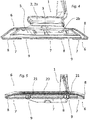
- Fig. 1 und 2:
- dreidimensionale Ansichten einer ersten Luftführungsanordnung für ein Kraftfahrzeug;
- Fig. 3:
- eine dreidimensionale Ansicht der Unterseite der ersten Luftführungsanordnung aus
Fig. 2 ; - Fig. 4 und 5:
- Querschnittsdarstellung der Luftführungsanordnungen aus
Fig. 1 und Fig. 2 ; - Fig. 6 und 7:
- dreidimensionale Ansichten einer zweiten Luftführungsanordnung für ein Kraftfahrzeug;
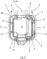
- Fig. 8:
- eine dreidimensionale Ansicht der Oberseite der zweiten Luftführungsanordnung aus
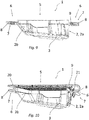
Fig. 6 ; - Fig. 9 und 10:
- Querschnittsdarstellung der Luftführungsanordnungen aus
Fig. 6 und Fig. 7 . - Die
Fig. 1 und Fig. 2 , sowie dieFig. 6 und Fig. 7 zeigen in einer dreidimensionalen Draufsichtsdarstellung eine Luftführungsanordnung für ein Kraftfahrzeug, mit - einem Luftführungskanal 1, wobei der Luftführungskanal 1 eine Kanalwandung 2 aufweist, die einen Hohlraum 3 zur Leitung der Luft begrenzt, der zwischen wenigstens einer ersten Durchtrittsöffnung 4 zum Eintritt von Luft und wenigstens einer zweiten Durchtrittsöffnung 5 zum Austritt von Luft liegt, und wobei die Kanalwandung 2 eine Außenseite 2a und eine Innenseite 2b aufweist.
- Der Luftführungskanal 1 ist einstückig in einem Blasformverfahren oder in einem Thermoformverfahren hergestellt. Der Luftführungskanal 1 weist im Bereich wenigstens einer seiner Durchtrittsöffnungen 4, 5 einen einstückig mit dem Luftführungskanal 1 ausgebildeten Verbindungsabschnitt 6 zum luftleitenden Verbinden des Luftführungskanals 1 mit einem weiteren Luftführungskanal oder zum luftleitenden Verbinden des Luftführungskanals 1 mit einem Luftverteilungselement 20 (vgl.
Fig. 2 oderFig. 7 ) auf. - Der Verbindungsabschnitt 6 ist ein die Durchtrittsöffnung 5 abschnittsweise oder vollständig umgebender Flansch 6 (vgl. auch
Fig. 3 undFig. 8 ). Der Flansch 6 ist zumindest bereichsweise doppelwandig ausgebildet und der Flansch 6 schließt in den doppelwandigen Bereichen 7 zwischen den sich gegenüberliegenden Flanschseiten einen Hohlraum 8 ein (vgl. Schnittdarstellungen inFig. 4 und Fig. 5 , sowieFig. 9 und Fig. 10 ). - Der Flansch 6 steht in dem zweiten Beispiel einer Luftführungsanordnung in einem rechten Winkel (vgl. insbesondere
Fig. 9 oder Fig. 10 ) oder-wie bei dem ersten Beispiel einer Luftführungsanordnung - in einem stumpfen Winkel (vgl. insbesondereFig. 3 oderFig. 5 ) von der Außenseite (2a) des Luftführungskanals ab. - Innerhalb des Flansches 6 ist bei beiden Ausführungsbeispielen mindestens eine Rastelementaufnahme 9 zur Verbindung mit einem Rastelement des weiteren Luftführungskanals oder zur Verbindung mit einem Rastelement 21 des Luftverteilungselements 20 ausgebildet. Die Rastelementaufnahme 9 ist hierbei jeweils ein den Flansch 6 durchsetzender Durchgang, wobei der Durchgang gegenüber dem Hohlraum 8 des Flansches 6 dicht ist. Das Rastelement 21 ist als Rastnase ausgebildet.
- 6Nicht näher dargestellt ist, dass auf dem Verbindungsabschnitt 6 ein Dichtungselement vorgesehen sein kann, zur Abdichtung gegenüber dem weiteren Luftführungskanal oder dem Luftverteilungselement 20.
- Der Luftführungskanal 1 beider Ausführungsbeispiele besteht aus einem thermoplastischen Material, wobei das thermoplastische Material ein Polyamid oder ein Polyolefin, insbesondere PE-HD umfassen kann.
- Die gezeigten Luftführungsanordnungen sind zur Fußraumbelüftung eines Kraftfahrzeuges vorgesehen.
- Die
Fig. 2 ,Fig. 3 ,Fig. 5 ,Fig. 7 und dieFig. 10 zeigen jeweils eine Luftführungsbaugruppe mit einer der beiden vorstehend beschriebenen Luftführungsanordnung und einem mit der Luftführungsanordnung verbundenen Luftverteilungselement 20. Das Luftverteilungselement 20 des ersten Ausführungsbeispiels (Fig. 2 ,Fig. 3 ,Fig. 5 ) ist ein mit Lamellen versehener Luftausströmer. Das Luftverteilungselement 20 des zweiten Ausführungsbeispiels (Fig. 7 undFig. 10 ) ist ein mit einem Gitter versehender Luftausströmer.
wobei der Verbindungsabschnitt ein die Durchtrittsöffnung abschnittsweise oder vollständig umgebender Flansch ist, wobei der Flansch zumindest bereichsweise doppelwandig ausgebildet ist und der Flansch in den doppelwandigen Bereichen zwischen den sich gegenüberliegenden Flanschseiten einen Hohlraum einschließt.
Claims (11)
- Luftführungsanordnung für ein Kraftfahrzeug, mit- einem Luftführungskanal (1), wobei der Luftführungskanal (1) eine Kanalwandung (2) aufweist, die einen Hohlraum (3) zur Leitung der Luft begrenzt, der zwischen wenigstens einer ersten Durchtrittsöffnung (4) zum Eintritt von Luft und wenigstens einer zweiten Durchtrittsöffnung (5) zum Austritt von Luft liegt, und wobei die Kanalwandung (2) eine Außenseite (2a) und eine Innenseite (2b) aufweist,wobei der Luftführungskanal (1) einstückig in einem Blasformverfahren oder in einem Thermoformverfahren hergestellt ist und,
wobei der Luftführungskanal (1) im Bereich wenigstens einer seiner Durchtrittsöffnungen (4, 5) einen einstückig mit dem Luftführungskanal (1) ausgebildeten Verbindungsabschnitt (6) zum luftleitenden Verbinden des Luftführungskanals (1) mit einem weiteren Luftführungskanal oder zum luftleitenden Verbinden des Luftführungskanals (1) mit einem Luftverteilungselement (20) aufweist,
dadurch gekennzeichnet, dass
der Verbindungsabschnitt (6) ein die Durchtrittsöffnung (5) abschnittsweise oder vollständig umgebender Flansch (6) ist, wobei der Flansch (6) zumindest bereichsweise doppelwandig ausgebildet ist und der Flansch (6) in den doppelwandigen Bereichen (7) zwischen den sich gegenüberliegenden Flanschseiten einen Hohlraum (8) einschließt. - Luftführungsanordnung nach Anspruch 1, dadurch gekennzeichnet, dass der Flansch (6) in einem rechten Winkel oder in einem stumpfen Winkel von der Außenseite (2a) des Luftführungskanals absteht.
- Luftführungsanordnung nach Anspruch 1 oder 2, dadurch gekennzeichnet, dass innerhalb des Flansches (6) mindestens eine Rastelementaufnahme (9) zur Verbindung mit einem Rastelement des weiteren Luftführungskanals oder zur Verbindung mit einem Rastelement (21) des Luftverteilungselements (20) ausgebildet ist.
- Luftführungsanordnung nach Anspruch 3, dadurch gekennzeichnet, dass die Rastelementaufnahme (9) ein den Flansch (6) durchsetzender Durchgang (9) ist.
- Luftführungsanordnung nach Anspruch 4, dadurch gekennzeichnet, dass der Durchgang gegenüber dem Hohlraum (8) des Flansches (6) dicht ist.
- Luftführungsanordnung nach einem der vorstehenden Ansprüche, dadurch gekennzeichnet, dass auf dem Verbindungsabschnitt (6) ein Dichtungselement vorgesehen ist, zur Abdichtung gegenüber dem weiteren Luftführungskanal oder dem Luftverteilungselement (20).
- Luftführungsanordnung nach einem der vorstehenden Ansprüche, dadurch gekennzeichnet, dass das der Luftführungskanal (1) aus einem thermoplastischen Material besteht.
- Luftführungsanordnung nach Anspruch 7, dadurch gekennzeichnet, dass das thermoplastische Material ein Polyamid oder ein Polyolefin, insbesondere PE-HD umfasst.
- Luftführungsanordnung nach einem der vorstehenden Ansprüche, dadurch gekennzeichnet, dass die Luftführungsanordnung zur Fußraumbelüftung eines Kraftfahrzeuges vorgesehen ist.
- Luftführungsbaugruppe mit einer Luftführungsanordnung nach einem der vorstehenden Ansprüche und einem mit der Luftführungsanordnung verbundenen weiteren Luftführungskanal oder einem mit der Luftführungsanordnung verbundenen Luftverteilungselement (20).
- Luftführungsbaugruppe nach Anspruch 10, dadurch gekennzeichnet, dass das Luftverteilungselement (20) ein mit einem Gitter oder mit Lamellen versehender Luftausströmer ist.
Applications Claiming Priority (1)
| Application Number | Priority Date | Filing Date | Title |
|---|---|---|---|
| DE202019107074.9U DE202019107074U1 (de) | 2019-12-18 | 2019-12-18 | Luftführungsanordnung |
Publications (2)
| Publication Number | Publication Date |
|---|---|
| EP3838636A1 true EP3838636A1 (de) | 2021-06-23 |
| EP3838636B1 EP3838636B1 (de) | 2022-11-02 |
Family
ID=73793078
Family Applications (1)
| Application Number | Title | Priority Date | Filing Date |
|---|---|---|---|
| EP20213102.5A Active EP3838636B1 (de) | 2019-12-18 | 2020-12-10 | Luftführungsanordnung |
Country Status (4)
| Country | Link |
|---|---|
| EP (1) | EP3838636B1 (de) |
| DE (1) | DE202019107074U1 (de) |
| HU (1) | HUE060994T2 (de) |
| PL (1) | PL3838636T3 (de) |
Citations (5)
| Publication number | Priority date | Publication date | Assignee | Title |
|---|---|---|---|---|
| DE69920556T2 (de) | 1998-03-13 | 2005-10-13 | Mazda Motor Corp. | Fahrzeug-Klimaanlage |
| JP2006248351A (ja) * | 2005-03-10 | 2006-09-21 | Denso Corp | 空調装置のダクト接続構造 |
| DE102007037734A1 (de) * | 2007-08-09 | 2009-02-12 | Behr Gmbh & Co. Kg | Luftströmungskanal aus einem Kunststoffschaum, insbesondere für ein Fahrzeug |
| DE202013105720U1 (de) * | 2013-12-17 | 2015-03-18 | Rehau Ag + Co | Luftfilteraufnahme aus einem thermoplastischen Kunststoffmaterial zum Einbau in den Motorraum eines Kraftfahrzeuges |
| DE202015106952U1 (de) * | 2015-12-21 | 2017-03-22 | Rehau Ag + Co | Luftführungsanordnung |
-
2019
- 2019-12-18 DE DE202019107074.9U patent/DE202019107074U1/de active Active
-
2020
- 2020-12-10 HU HUE20213102A patent/HUE060994T2/hu unknown
- 2020-12-10 EP EP20213102.5A patent/EP3838636B1/de active Active
- 2020-12-10 PL PL20213102.5T patent/PL3838636T3/pl unknown
Patent Citations (5)
| Publication number | Priority date | Publication date | Assignee | Title |
|---|---|---|---|---|
| DE69920556T2 (de) | 1998-03-13 | 2005-10-13 | Mazda Motor Corp. | Fahrzeug-Klimaanlage |
| JP2006248351A (ja) * | 2005-03-10 | 2006-09-21 | Denso Corp | 空調装置のダクト接続構造 |
| DE102007037734A1 (de) * | 2007-08-09 | 2009-02-12 | Behr Gmbh & Co. Kg | Luftströmungskanal aus einem Kunststoffschaum, insbesondere für ein Fahrzeug |
| DE202013105720U1 (de) * | 2013-12-17 | 2015-03-18 | Rehau Ag + Co | Luftfilteraufnahme aus einem thermoplastischen Kunststoffmaterial zum Einbau in den Motorraum eines Kraftfahrzeuges |
| DE202015106952U1 (de) * | 2015-12-21 | 2017-03-22 | Rehau Ag + Co | Luftführungsanordnung |
Also Published As
| Publication number | Publication date |
|---|---|
| PL3838636T3 (pl) | 2023-03-06 |
| EP3838636B1 (de) | 2022-11-02 |
| DE202019107074U1 (de) | 2021-03-19 |
| HUE060994T2 (hu) | 2023-04-28 |
Similar Documents
| Publication | Publication Date | Title |
|---|---|---|
| DE102014201675B4 (de) | Befestigungsanordnung für eine elektrische baugruppe eines fahrzeugs | |
| WO2016177364A1 (de) | Anordnung mit einer wanddurchführung für mehrere kabel sowie verfahren zum herstellen und bausatz | |
| EP0438076A2 (de) | Belüftungseinrichtung für Fahrzeugkabine | |
| DE102018203428B3 (de) | Fahrzeug mit einer Klimaanordnung | |
| DE102015223596A1 (de) | Druckausgleichsvorrichtung und elektronisches Steuermodul mit der Druckausgleichsvorrichtung. | |
| DE102010018502A1 (de) | Versorgungssystem zur Versorgung von Passagieren in einem Passagierraum eines Fahrzeugs | |
| DE102007002679A1 (de) | Kraftfahrzeug mit einer Unterbodenverkleidung | |
| DE19926858C2 (de) | Befestigungsanordnung für einen Kabelstrang in einem Armaturenbrett | |
| DE102015113538A1 (de) | HAVC-Kanal mit Schwenkbogen | |
| DE102007002567A1 (de) | Außenspiegel eines Kraftfahrzeuges | |
| DE112013003819B4 (de) | Fahrzeugseitenentfrosteraufbau | |
| DE102019111746A1 (de) | Lüftungsvorrichtung für eine Seitenscheibe und den Innenraum eines Personenkraftwagens sowie hiermit ausgestatteter Personenkraftwagen | |
| DE202021101741U1 (de) | Flachkanalanordnung für eine Downdraft-Dunstabzugshaube | |
| DE202015102766U1 (de) | Defrosterdüse mit Netz über dem Auslass | |
| EP3838636B1 (de) | Luftführungsanordnung | |
| DE102019116678A1 (de) | Kraftfahrzeug mit Coanda-Effekt erlaubender Instrumententafel | |
| EP2851258A1 (de) | Lüftungskanal und Fahrzeug mit entsprechendem Lüftungskanal | |
| EP3034337B1 (de) | Luftführungssystem für ein kraftfahrzeug | |
| DE102010060613B4 (de) | Trennelement mit Lüftungskanälen | |
| DE102008010182A1 (de) | Gehäuse für eine Gasfördereinrichtung | |
| DE102014212899B4 (de) | Kombiinstrument in einem Kraftfahrzeug und blendenartiges Bauteil | |
| DE102011051185A1 (de) | Luftausströmvorrichtung | |
| EP3098100A1 (de) | Luftführungsanordnung für ein kraftfahrzeug sowie verfahren zur herstellung einer luftführungsanordnung für ein kraftfahrzeug | |
| DE202023107570U1 (de) | Luftführungssystem für ein Kraftfahrzeug | |
| DE202018107204U1 (de) | Mehrteiliges Verkleidungsteil für ein Kraftfahrzeug |
Legal Events
| Date | Code | Title | Description |
|---|---|---|---|
| PUAI | Public reference made under article 153(3) epc to a published international application that has entered the european phase |
Free format text: ORIGINAL CODE: 0009012 |
|
| STAA | Information on the status of an ep patent application or granted ep patent |
Free format text: STATUS: THE APPLICATION HAS BEEN PUBLISHED |
|
| AK | Designated contracting states |
Kind code of ref document: A1 Designated state(s): AL AT BE BG CH CY CZ DE DK EE ES FI FR GB GR HR HU IE IS IT LI LT LU LV MC MK MT NL NO PL PT RO RS SE SI SK SM TR |
|
| STAA | Information on the status of an ep patent application or granted ep patent |
Free format text: STATUS: REQUEST FOR EXAMINATION WAS MADE |
|
| 17P | Request for examination filed |
Effective date: 20211209 |
|
| RBV | Designated contracting states (corrected) |
Designated state(s): AL AT BE BG CH CY CZ DE DK EE ES FI FR GB GR HR HU IE IS IT LI LT LU LV MC MK MT NL NO PL PT RO RS SE SI SK SM TR |
|
| RAP3 | Party data changed (applicant data changed or rights of an application transferred) |
Owner name: REHAU AUTOMOTIVE SE & CO. KG |
|
| GRAP | Despatch of communication of intention to grant a patent |
Free format text: ORIGINAL CODE: EPIDOSNIGR1 |
|
| STAA | Information on the status of an ep patent application or granted ep patent |
Free format text: STATUS: GRANT OF PATENT IS INTENDED |
|
| INTG | Intention to grant announced |
Effective date: 20220516 |
|
| RAP3 | Party data changed (applicant data changed or rights of an application transferred) |
Owner name: REHAU INDUSTRIES SE & CO. KG |
|
| RAP3 | Party data changed (applicant data changed or rights of an application transferred) |
Owner name: REHAU AUTOMOTIVE SE & CO. KG |
|
| GRAS | Grant fee paid |
Free format text: ORIGINAL CODE: EPIDOSNIGR3 |
|
| GRAA | (expected) grant |
Free format text: ORIGINAL CODE: 0009210 |
|
| STAA | Information on the status of an ep patent application or granted ep patent |
Free format text: STATUS: THE PATENT HAS BEEN GRANTED |
|
| AK | Designated contracting states |
Kind code of ref document: B1 Designated state(s): AL AT BE BG CH CY CZ DE DK EE ES FI FR GB GR HR HU IE IS IT LI LT LU LV MC MK MT NL NO PL PT RO RS SE SI SK SM TR |
|
| REG | Reference to a national code |
Ref country code: GB Ref legal event code: FG4D Free format text: NOT ENGLISH |
|
| REG | Reference to a national code |
Ref country code: CH Ref legal event code: EP Ref country code: AT Ref legal event code: REF Ref document number: 1528517 Country of ref document: AT Kind code of ref document: T Effective date: 20221115 |
|
| REG | Reference to a national code |
Ref country code: DE Ref legal event code: R096 Ref document number: 502020001933 Country of ref document: DE |
|
| REG | Reference to a national code |
Ref country code: IE Ref legal event code: FG4D Free format text: LANGUAGE OF EP DOCUMENT: GERMAN |
|
| REG | Reference to a national code |
Ref country code: LT Ref legal event code: MG9D |
|
| REG | Reference to a national code |
Ref country code: NL Ref legal event code: MP Effective date: 20221102 |
|
| PG25 | Lapsed in a contracting state [announced via postgrant information from national office to epo] |
Ref country code: SE Free format text: LAPSE BECAUSE OF FAILURE TO SUBMIT A TRANSLATION OF THE DESCRIPTION OR TO PAY THE FEE WITHIN THE PRESCRIBED TIME-LIMIT Effective date: 20221102 Ref country code: PT Free format text: LAPSE BECAUSE OF FAILURE TO SUBMIT A TRANSLATION OF THE DESCRIPTION OR TO PAY THE FEE WITHIN THE PRESCRIBED TIME-LIMIT Effective date: 20230302 Ref country code: NO Free format text: LAPSE BECAUSE OF FAILURE TO SUBMIT A TRANSLATION OF THE DESCRIPTION OR TO PAY THE FEE WITHIN THE PRESCRIBED TIME-LIMIT Effective date: 20230202 Ref country code: LT Free format text: LAPSE BECAUSE OF FAILURE TO SUBMIT A TRANSLATION OF THE DESCRIPTION OR TO PAY THE FEE WITHIN THE PRESCRIBED TIME-LIMIT Effective date: 20221102 Ref country code: FI Free format text: LAPSE BECAUSE OF FAILURE TO SUBMIT A TRANSLATION OF THE DESCRIPTION OR TO PAY THE FEE WITHIN THE PRESCRIBED TIME-LIMIT Effective date: 20221102 Ref country code: ES Free format text: LAPSE BECAUSE OF FAILURE TO SUBMIT A TRANSLATION OF THE DESCRIPTION OR TO PAY THE FEE WITHIN THE PRESCRIBED TIME-LIMIT Effective date: 20221102 |
|
| REG | Reference to a national code |
Ref country code: HU Ref legal event code: AG4A Ref document number: E060994 Country of ref document: HU |
|
| PG25 | Lapsed in a contracting state [announced via postgrant information from national office to epo] |
Ref country code: RS Free format text: LAPSE BECAUSE OF FAILURE TO SUBMIT A TRANSLATION OF THE DESCRIPTION OR TO PAY THE FEE WITHIN THE PRESCRIBED TIME-LIMIT Effective date: 20221102 Ref country code: LV Free format text: LAPSE BECAUSE OF FAILURE TO SUBMIT A TRANSLATION OF THE DESCRIPTION OR TO PAY THE FEE WITHIN THE PRESCRIBED TIME-LIMIT Effective date: 20221102 Ref country code: IS Free format text: LAPSE BECAUSE OF FAILURE TO SUBMIT A TRANSLATION OF THE DESCRIPTION OR TO PAY THE FEE WITHIN THE PRESCRIBED TIME-LIMIT Effective date: 20230302 Ref country code: HR Free format text: LAPSE BECAUSE OF FAILURE TO SUBMIT A TRANSLATION OF THE DESCRIPTION OR TO PAY THE FEE WITHIN THE PRESCRIBED TIME-LIMIT Effective date: 20221102 Ref country code: GR Free format text: LAPSE BECAUSE OF FAILURE TO SUBMIT A TRANSLATION OF THE DESCRIPTION OR TO PAY THE FEE WITHIN THE PRESCRIBED TIME-LIMIT Effective date: 20230203 |
|
| PG25 | Lapsed in a contracting state [announced via postgrant information from national office to epo] |
Ref country code: NL Free format text: LAPSE BECAUSE OF FAILURE TO SUBMIT A TRANSLATION OF THE DESCRIPTION OR TO PAY THE FEE WITHIN THE PRESCRIBED TIME-LIMIT Effective date: 20221102 |
|
| P01 | Opt-out of the competence of the unified patent court (upc) registered |
Effective date: 20230529 |
|
| PG25 | Lapsed in a contracting state [announced via postgrant information from national office to epo] |
Ref country code: SM Free format text: LAPSE BECAUSE OF FAILURE TO SUBMIT A TRANSLATION OF THE DESCRIPTION OR TO PAY THE FEE WITHIN THE PRESCRIBED TIME-LIMIT Effective date: 20221102 Ref country code: RO Free format text: LAPSE BECAUSE OF FAILURE TO SUBMIT A TRANSLATION OF THE DESCRIPTION OR TO PAY THE FEE WITHIN THE PRESCRIBED TIME-LIMIT Effective date: 20221102 Ref country code: EE Free format text: LAPSE BECAUSE OF FAILURE TO SUBMIT A TRANSLATION OF THE DESCRIPTION OR TO PAY THE FEE WITHIN THE PRESCRIBED TIME-LIMIT Effective date: 20221102 Ref country code: DK Free format text: LAPSE BECAUSE OF FAILURE TO SUBMIT A TRANSLATION OF THE DESCRIPTION OR TO PAY THE FEE WITHIN THE PRESCRIBED TIME-LIMIT Effective date: 20221102 |
|
| REG | Reference to a national code |
Ref country code: DE Ref legal event code: R097 Ref document number: 502020001933 Country of ref document: DE |
|
| REG | Reference to a national code |
Ref country code: BE Ref legal event code: MM Effective date: 20221231 |
|
| PG25 | Lapsed in a contracting state [announced via postgrant information from national office to epo] |
Ref country code: SK Free format text: LAPSE BECAUSE OF FAILURE TO SUBMIT A TRANSLATION OF THE DESCRIPTION OR TO PAY THE FEE WITHIN THE PRESCRIBED TIME-LIMIT Effective date: 20221102 Ref country code: LU Free format text: LAPSE BECAUSE OF NON-PAYMENT OF DUE FEES Effective date: 20221210 Ref country code: AL Free format text: LAPSE BECAUSE OF FAILURE TO SUBMIT A TRANSLATION OF THE DESCRIPTION OR TO PAY THE FEE WITHIN THE PRESCRIBED TIME-LIMIT Effective date: 20221102 |
|
| PLBE | No opposition filed within time limit |
Free format text: ORIGINAL CODE: 0009261 |
|
| STAA | Information on the status of an ep patent application or granted ep patent |
Free format text: STATUS: NO OPPOSITION FILED WITHIN TIME LIMIT |
|
| 26N | No opposition filed |
Effective date: 20230803 |
|
| PG25 | Lapsed in a contracting state [announced via postgrant information from national office to epo] |
Ref country code: IE Free format text: LAPSE BECAUSE OF NON-PAYMENT OF DUE FEES Effective date: 20221210 |
|
| PG25 | Lapsed in a contracting state [announced via postgrant information from national office to epo] |
Ref country code: SI Free format text: LAPSE BECAUSE OF FAILURE TO SUBMIT A TRANSLATION OF THE DESCRIPTION OR TO PAY THE FEE WITHIN THE PRESCRIBED TIME-LIMIT Effective date: 20221102 Ref country code: FR Free format text: LAPSE BECAUSE OF NON-PAYMENT OF DUE FEES Effective date: 20230102 Ref country code: BE Free format text: LAPSE BECAUSE OF NON-PAYMENT OF DUE FEES Effective date: 20221231 |
|
| PG25 | Lapsed in a contracting state [announced via postgrant information from national office to epo] |
Ref country code: CY Free format text: LAPSE BECAUSE OF FAILURE TO SUBMIT A TRANSLATION OF THE DESCRIPTION OR TO PAY THE FEE WITHIN THE PRESCRIBED TIME-LIMIT Effective date: 20221102 |
|
| PG25 | Lapsed in a contracting state [announced via postgrant information from national office to epo] |
Ref country code: MK Free format text: LAPSE BECAUSE OF FAILURE TO SUBMIT A TRANSLATION OF THE DESCRIPTION OR TO PAY THE FEE WITHIN THE PRESCRIBED TIME-LIMIT Effective date: 20221102 Ref country code: IT Free format text: LAPSE BECAUSE OF FAILURE TO SUBMIT A TRANSLATION OF THE DESCRIPTION OR TO PAY THE FEE WITHIN THE PRESCRIBED TIME-LIMIT Effective date: 20221102 |
|
| PG25 | Lapsed in a contracting state [announced via postgrant information from national office to epo] |
Ref country code: MC Free format text: LAPSE BECAUSE OF FAILURE TO SUBMIT A TRANSLATION OF THE DESCRIPTION OR TO PAY THE FEE WITHIN THE PRESCRIBED TIME-LIMIT Effective date: 20221102 |
|
| PG25 | Lapsed in a contracting state [announced via postgrant information from national office to epo] |
Ref country code: TR Free format text: LAPSE BECAUSE OF FAILURE TO SUBMIT A TRANSLATION OF THE DESCRIPTION OR TO PAY THE FEE WITHIN THE PRESCRIBED TIME-LIMIT Effective date: 20221102 Ref country code: MC Free format text: LAPSE BECAUSE OF FAILURE TO SUBMIT A TRANSLATION OF THE DESCRIPTION OR TO PAY THE FEE WITHIN THE PRESCRIBED TIME-LIMIT Effective date: 20221102 |
|
| PG25 | Lapsed in a contracting state [announced via postgrant information from national office to epo] |
Ref country code: BG Free format text: LAPSE BECAUSE OF FAILURE TO SUBMIT A TRANSLATION OF THE DESCRIPTION OR TO PAY THE FEE WITHIN THE PRESCRIBED TIME-LIMIT Effective date: 20221102 |
|
| REG | Reference to a national code |
Ref country code: CH Ref legal event code: PL |
|
| PG25 | Lapsed in a contracting state [announced via postgrant information from national office to epo] |
Ref country code: MT Free format text: LAPSE BECAUSE OF FAILURE TO SUBMIT A TRANSLATION OF THE DESCRIPTION OR TO PAY THE FEE WITHIN THE PRESCRIBED TIME-LIMIT Effective date: 20221102 |
|
| PG25 | Lapsed in a contracting state [announced via postgrant information from national office to epo] |
Ref country code: CH Free format text: LAPSE BECAUSE OF NON-PAYMENT OF DUE FEES Effective date: 20231231 |
|
| PG25 | Lapsed in a contracting state [announced via postgrant information from national office to epo] |
Ref country code: CH Free format text: LAPSE BECAUSE OF NON-PAYMENT OF DUE FEES Effective date: 20231231 |
|
| REG | Reference to a national code |
Ref country code: DE Ref legal event code: R081 Ref document number: 502020001933 Country of ref document: DE Owner name: RESRG AUTOMOTIVE SE & CO. KG, DE Free format text: FORMER OWNER: REHAU AUTOMOTIVE SE & CO. KG, 95111 REHAU, DE |
|
| GBPC | Gb: european patent ceased through non-payment of renewal fee |
Effective date: 20241210 |
|
| PG25 | Lapsed in a contracting state [announced via postgrant information from national office to epo] |
Ref country code: GB Free format text: LAPSE BECAUSE OF NON-PAYMENT OF DUE FEES Effective date: 20241210 |
|
| PGFP | Annual fee paid to national office [announced via postgrant information from national office to epo] |
Ref country code: AT Payment date: 20260113 Year of fee payment: 5 |
|
| PGFP | Annual fee paid to national office [announced via postgrant information from national office to epo] |
Ref country code: HU Payment date: 20251107 Year of fee payment: 6 |
|
| PGFP | Annual fee paid to national office [announced via postgrant information from national office to epo] |
Ref country code: CZ Payment date: 20251027 Year of fee payment: 6 |
|
| PGFP | Annual fee paid to national office [announced via postgrant information from national office to epo] |
Ref country code: PL Payment date: 20251024 Year of fee payment: 6 |
|
| PGFP | Annual fee paid to national office [announced via postgrant information from national office to epo] |
Ref country code: DE Payment date: 20251231 Year of fee payment: 6 |
|
| PG25 | Lapsed in a contracting state [announced via postgrant information from national office to epo] |
Ref country code: CH Free format text: THE PATENT HAS BEEN ANNULLED BY A DECISION OF A NATIONAL AUTHORITY Effective date: 20231231 |