EP3836296B1 - Battery module having structure capable of preventing inflow of air into module when thermal runaway occurs and battery pack including same - Google Patents
Battery module having structure capable of preventing inflow of air into module when thermal runaway occurs and battery pack including same Download PDFInfo
- Publication number
- EP3836296B1 EP3836296B1 EP20765773.5A EP20765773A EP3836296B1 EP 3836296 B1 EP3836296 B1 EP 3836296B1 EP 20765773 A EP20765773 A EP 20765773A EP 3836296 B1 EP3836296 B1 EP 3836296B1
- Authority
- EP
- European Patent Office
- Prior art keywords
- module
- battery
- battery module
- sealing portion
- case
- Prior art date
- Legal status (The legal status is an assumption and is not a legal conclusion. Google has not performed a legal analysis and makes no representation as to the accuracy of the status listed.)
- Active
Links
Images


Classifications
-
- H—ELECTRICITY
- H01—ELECTRIC ELEMENTS
- H01M—PROCESSES OR MEANS, e.g. BATTERIES, FOR THE DIRECT CONVERSION OF CHEMICAL ENERGY INTO ELECTRICAL ENERGY
- H01M10/00—Secondary cells; Manufacture thereof
- H01M10/60—Heating or cooling; Temperature control
- H01M10/65—Means for temperature control structurally associated with the cells
- H01M10/658—Means for temperature control structurally associated with the cells by thermal insulation or shielding
-
- A—HUMAN NECESSITIES
- A62—LIFE-SAVING; FIRE-FIGHTING
- A62C—FIRE-FIGHTING
- A62C2/00—Fire prevention or containment
- A62C2/06—Physical fire-barriers
-
- A—HUMAN NECESSITIES
- A62—LIFE-SAVING; FIRE-FIGHTING
- A62C—FIRE-FIGHTING
- A62C2/00—Fire prevention or containment
- A62C2/06—Physical fire-barriers
- A62C2/065—Physical fire-barriers having as the main closure device materials, whose characteristics undergo an irreversible change under high temperatures, e.g. intumescent
-
- A—HUMAN NECESSITIES
- A62—LIFE-SAVING; FIRE-FIGHTING
- A62C—FIRE-FIGHTING
- A62C3/00—Fire prevention, containment or extinguishing specially adapted for particular objects or places
- A62C3/16—Fire prevention, containment or extinguishing specially adapted for particular objects or places in electrical installations, e.g. cableways
-
- H—ELECTRICITY
- H01—ELECTRIC ELEMENTS
- H01M—PROCESSES OR MEANS, e.g. BATTERIES, FOR THE DIRECT CONVERSION OF CHEMICAL ENERGY INTO ELECTRICAL ENERGY
- H01M10/00—Secondary cells; Manufacture thereof
- H01M10/60—Heating or cooling; Temperature control
- H01M10/61—Types of temperature control
- H01M10/613—Cooling or keeping cold
-
- H—ELECTRICITY
- H01—ELECTRIC ELEMENTS
- H01M—PROCESSES OR MEANS, e.g. BATTERIES, FOR THE DIRECT CONVERSION OF CHEMICAL ENERGY INTO ELECTRICAL ENERGY
- H01M10/00—Secondary cells; Manufacture thereof
- H01M10/60—Heating or cooling; Temperature control
- H01M10/65—Means for temperature control structurally associated with the cells
- H01M10/656—Means for temperature control structurally associated with the cells characterised by the type of heat-exchange fluid
- H01M10/6561—Gases
- H01M10/6562—Gases with free flow by convection only
-
- H—ELECTRICITY
- H01—ELECTRIC ELEMENTS
- H01M—PROCESSES OR MEANS, e.g. BATTERIES, FOR THE DIRECT CONVERSION OF CHEMICAL ENERGY INTO ELECTRICAL ENERGY
- H01M10/00—Secondary cells; Manufacture thereof
- H01M10/60—Heating or cooling; Temperature control
- H01M10/65—Means for temperature control structurally associated with the cells
- H01M10/656—Means for temperature control structurally associated with the cells characterised by the type of heat-exchange fluid
- H01M10/6561—Gases
- H01M10/6563—Gases with forced flow, e.g. by blowers
-
- H—ELECTRICITY
- H01—ELECTRIC ELEMENTS
- H01M—PROCESSES OR MEANS, e.g. BATTERIES, FOR THE DIRECT CONVERSION OF CHEMICAL ENERGY INTO ELECTRICAL ENERGY
- H01M50/00—Constructional details or processes of manufacture of the non-active parts of electrochemical cells other than fuel cells, e.g. hybrid cells
- H01M50/20—Mountings; Secondary casings or frames; Racks, modules or packs; Suspension devices; Shock absorbers; Transport or carrying devices; Holders
- H01M50/204—Racks, modules or packs for multiple batteries or multiple cells
- H01M50/207—Racks, modules or packs for multiple batteries or multiple cells characterised by their shape
- H01M50/209—Racks, modules or packs for multiple batteries or multiple cells characterised by their shape adapted for prismatic or rectangular cells
-
- H—ELECTRICITY
- H01—ELECTRIC ELEMENTS
- H01M—PROCESSES OR MEANS, e.g. BATTERIES, FOR THE DIRECT CONVERSION OF CHEMICAL ENERGY INTO ELECTRICAL ENERGY
- H01M50/00—Constructional details or processes of manufacture of the non-active parts of electrochemical cells other than fuel cells, e.g. hybrid cells
- H01M50/20—Mountings; Secondary casings or frames; Racks, modules or packs; Suspension devices; Shock absorbers; Transport or carrying devices; Holders
- H01M50/204—Racks, modules or packs for multiple batteries or multiple cells
- H01M50/207—Racks, modules or packs for multiple batteries or multiple cells characterised by their shape
- H01M50/211—Racks, modules or packs for multiple batteries or multiple cells characterised by their shape adapted for pouch cells
-
- H—ELECTRICITY
- H01—ELECTRIC ELEMENTS
- H01M—PROCESSES OR MEANS, e.g. BATTERIES, FOR THE DIRECT CONVERSION OF CHEMICAL ENERGY INTO ELECTRICAL ENERGY
- H01M50/00—Constructional details or processes of manufacture of the non-active parts of electrochemical cells other than fuel cells, e.g. hybrid cells
- H01M50/20—Mountings; Secondary casings or frames; Racks, modules or packs; Suspension devices; Shock absorbers; Transport or carrying devices; Holders
- H01M50/218—Mountings; Secondary casings or frames; Racks, modules or packs; Suspension devices; Shock absorbers; Transport or carrying devices; Holders characterised by the material
- H01M50/22—Mountings; Secondary casings or frames; Racks, modules or packs; Suspension devices; Shock absorbers; Transport or carrying devices; Holders characterised by the material of the casings or racks
- H01M50/222—Inorganic material
- H01M50/224—Metals
-
- H—ELECTRICITY
- H01—ELECTRIC ELEMENTS
- H01M—PROCESSES OR MEANS, e.g. BATTERIES, FOR THE DIRECT CONVERSION OF CHEMICAL ENERGY INTO ELECTRICAL ENERGY
- H01M50/00—Constructional details or processes of manufacture of the non-active parts of electrochemical cells other than fuel cells, e.g. hybrid cells
- H01M50/20—Mountings; Secondary casings or frames; Racks, modules or packs; Suspension devices; Shock absorbers; Transport or carrying devices; Holders
- H01M50/233—Mountings; Secondary casings or frames; Racks, modules or packs; Suspension devices; Shock absorbers; Transport or carrying devices; Holders characterised by physical properties of casings or racks, e.g. dimensions
- H01M50/24—Mountings; Secondary casings or frames; Racks, modules or packs; Suspension devices; Shock absorbers; Transport or carrying devices; Holders characterised by physical properties of casings or racks, e.g. dimensions adapted for protecting batteries from their environment, e.g. from corrosion
-
- H—ELECTRICITY
- H01—ELECTRIC ELEMENTS
- H01M—PROCESSES OR MEANS, e.g. BATTERIES, FOR THE DIRECT CONVERSION OF CHEMICAL ENERGY INTO ELECTRICAL ENERGY
- H01M50/00—Constructional details or processes of manufacture of the non-active parts of electrochemical cells other than fuel cells, e.g. hybrid cells
- H01M50/20—Mountings; Secondary casings or frames; Racks, modules or packs; Suspension devices; Shock absorbers; Transport or carrying devices; Holders
- H01M50/258—Modular batteries; Casings provided with means for assembling
-
- H—ELECTRICITY
- H01—ELECTRIC ELEMENTS
- H01M—PROCESSES OR MEANS, e.g. BATTERIES, FOR THE DIRECT CONVERSION OF CHEMICAL ENERGY INTO ELECTRICAL ENERGY
- H01M50/00—Constructional details or processes of manufacture of the non-active parts of electrochemical cells other than fuel cells, e.g. hybrid cells
- H01M50/20—Mountings; Secondary casings or frames; Racks, modules or packs; Suspension devices; Shock absorbers; Transport or carrying devices; Holders
- H01M50/271—Lids or covers for the racks or secondary casings
- H01M50/273—Lids or covers for the racks or secondary casings characterised by the material
-
- H—ELECTRICITY
- H01—ELECTRIC ELEMENTS
- H01M—PROCESSES OR MEANS, e.g. BATTERIES, FOR THE DIRECT CONVERSION OF CHEMICAL ENERGY INTO ELECTRICAL ENERGY
- H01M50/00—Constructional details or processes of manufacture of the non-active parts of electrochemical cells other than fuel cells, e.g. hybrid cells
- H01M50/30—Arrangements for facilitating escape of gases
- H01M50/317—Re-sealable arrangements
- H01M50/325—Re-sealable arrangements comprising deformable valve members, e.g. elastic or flexible valve members
- H01M50/333—Spring-loaded vent valves
-
- H—ELECTRICITY
- H01—ELECTRIC ELEMENTS
- H01M—PROCESSES OR MEANS, e.g. BATTERIES, FOR THE DIRECT CONVERSION OF CHEMICAL ENERGY INTO ELECTRICAL ENERGY
- H01M50/00—Constructional details or processes of manufacture of the non-active parts of electrochemical cells other than fuel cells, e.g. hybrid cells
- H01M50/30—Arrangements for facilitating escape of gases
- H01M50/375—Vent means sensitive to or responsive to temperature
-
- H—ELECTRICITY
- H01—ELECTRIC ELEMENTS
- H01M—PROCESSES OR MEANS, e.g. BATTERIES, FOR THE DIRECT CONVERSION OF CHEMICAL ENERGY INTO ELECTRICAL ENERGY
- H01M50/00—Constructional details or processes of manufacture of the non-active parts of electrochemical cells other than fuel cells, e.g. hybrid cells
- H01M50/30—Arrangements for facilitating escape of gases
- H01M50/383—Flame arresting or ignition-preventing means
-
- H—ELECTRICITY
- H01—ELECTRIC ELEMENTS
- H01M—PROCESSES OR MEANS, e.g. BATTERIES, FOR THE DIRECT CONVERSION OF CHEMICAL ENERGY INTO ELECTRICAL ENERGY
- H01M50/00—Constructional details or processes of manufacture of the non-active parts of electrochemical cells other than fuel cells, e.g. hybrid cells
- H01M50/30—Arrangements for facilitating escape of gases
- H01M50/394—Gas-pervious parts or elements
-
- H—ELECTRICITY
- H01—ELECTRIC ELEMENTS
- H01M—PROCESSES OR MEANS, e.g. BATTERIES, FOR THE DIRECT CONVERSION OF CHEMICAL ENERGY INTO ELECTRICAL ENERGY
- H01M2200/00—Safety devices for primary or secondary batteries
- H01M2200/10—Temperature sensitive devices
-
- H—ELECTRICITY
- H01—ELECTRIC ELEMENTS
- H01M—PROCESSES OR MEANS, e.g. BATTERIES, FOR THE DIRECT CONVERSION OF CHEMICAL ENERGY INTO ELECTRICAL ENERGY
- H01M2200/00—Safety devices for primary or secondary batteries
- H01M2200/20—Pressure-sensitive devices
-
- Y—GENERAL TAGGING OF NEW TECHNOLOGICAL DEVELOPMENTS; GENERAL TAGGING OF CROSS-SECTIONAL TECHNOLOGIES SPANNING OVER SEVERAL SECTIONS OF THE IPC; TECHNICAL SUBJECTS COVERED BY FORMER USPC CROSS-REFERENCE ART COLLECTIONS [XRACs] AND DIGESTS
- Y02—TECHNOLOGIES OR APPLICATIONS FOR MITIGATION OR ADAPTATION AGAINST CLIMATE CHANGE
- Y02E—REDUCTION OF GREENHOUSE GAS [GHG] EMISSIONS, RELATED TO ENERGY GENERATION, TRANSMISSION OR DISTRIBUTION
- Y02E60/00—Enabling technologies; Technologies with a potential or indirect contribution to GHG emissions mitigation
- Y02E60/10—Energy storage using batteries
Definitions
- the present disclosure relates to a battery module according to the preamble of claim 1 having a structure capable of blocking air introduction into a module when a thermal runaway phenomenon occurs, and a battery pack including the battery module. More specifically, the present disclosure relates to a battery module having a structure capable of blocking introduction of an external air and just allowing gas discharge to the outside when a temperature in the battery module increases, by applying a thermally expanding material to an inner edge of a module case and applying a one-way venting valve and a thermally expanding material to an inner portion of a ventilation unit for cooling, and a battery pack including the battery module.
- a thermal runaway phenomenon occurs in some battery cells as described above, safety issues may be generated.
- the flame If a flame or the like is generated due to the thermal runaway phenomenon occurring in some battery cells, the flame rapidly raises the temperature of adjacent battery cells, and thus the thermal runaway phenomenon may be propagated to adjacent cells within a short time.
- a battery module adopting an air-cooled structure must have a structure capable of allowing an air to flow smoothly from the outside of the battery module to the inside thereof.
- a battery module adopting an air-cooled structure is disclosed in JP 2013 246920 . Therefore, there is a demand to develop a battery module having a structure capable of quickly discharging a venting gas generated therein to the outside while completely blocking the air introduced therein when a thermal runaway phenomenon occurs inside the battery module.
- the present invention is designed to solve the problems of the related art, and therefore the present invention is directed to providing a battery module having a structure capable of quickly discharging a venting gas generated therein to the outside while completely blocking the air introduced therein in order to prevent the flame from spreading further when a thermal runaway phenomenon occurs inside the battery module.
- a battery module comprising: a cell stack having a plurality of battery cells; a module case configured to accommodate the cell stack; a pair of module covers configured to cover openings at both sides of the module case; and a ventilation unit installed through the module cover, wherein the ventilation unit includes: a one-way venting valve disposed at a center of a perforation hole formed through the module cover; a first hole sealing portion attached onto an inner wall of the perforation hole; and a second hole sealing portion attached onto an outer circumference of the one-way venting valve.
- the first hole sealing portion and the second hole sealing portion are expanded at a reference temperature or above to meet each other so that the perforation hole is sealed.
- the first hole sealing portion and the second hole sealing portion may be made of a sheet containing at least one of an epoxy-based resin, a butyl-based resin and a vinyl chloride-based resin.
- the one-way venting valve may discharge a venting gas from an inside thereof to the outside when a pressure inside the module case is a reference pressure or above.
- the ventilation unit may include a valve support configured to traverse the perforation hole, and the one-way venting valve may be fixed to the valve support.
- the battery module may further comprise a case sealing portion attached onto an inner edge of the module case and a border area where an inner surface of the module case meets the module cover.
- the case sealing portion may be expanded at a reference temperature or above to reinforce airtightness of the module case.
- the one-way venting valve may include a lower cap having at least one first flow path; an upper cap having at least one second flow path and coupled to an upper portion of the lower cap to form an inner space; and a flow path cover located in the inner space and installed to cover the second flow path as being elastically pressed from the upper cap toward the lower cap.
- the one-way venting valve may be made of an elastic material and has a funnel shape having an inner space gradually narrowed outward from an inner side of the module case so that facing surfaces at a top end thereof are in contact with each other.
- a battery pack according to an embodiment of the present invention includes a plurality of battery modules according to an embodiment of the present invention as described above.
- the battery module having a air-cooled structure may quickly discharge a venting gas generated therein to the outside while completely blocking the air introduced therein in order to prevent the flame from spreading further when a thermal runaway phenomenon occurs therein, thereby securing the safety of the battery module in use.
- a battery module includes a cell stack 100, a module case 200, a case sealing portion 250, a module cover 300, and a ventilation unit 400.
- the cell stack 100 is formed by stacking a plurality of battery cells 110.
- the battery cell 110 for example, a pouch-type battery cell may be applied.
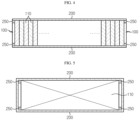
- the module case 200 has an approximately rectangular parallelepiped shape with openings at both longitudinal sides thereof.
- the module case 200 may be made of a metal material such as aluminum to secure rigidity.
- the module case 200 may include an upper plate for covering an upper portion of the cell stack 100, a lower plate for covering a lower portion of the cell stack 100, and side plates for covering both sides of the cell stack 100.
- the coupling between the upper plate and the side plate and the coupling between the lower plate and the side plate may be performed by welding.
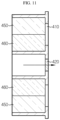
- the case sealing portion 250 is attached on a border area where an inner edge of the module case 200 and an inner surface of the module case 200 meet the module cover 300. That is, the case sealing portion 250 is attached on a border area where the upper plate and the side plate of the module case 200 meet, a border area where the lower plate and the side plate meet, and a periphery of the inner surface of the opening of the module case 200.
- the case sealing portion 250 is expanded at a reference temperature or above to enhance the airtightness of the module case 200. If a problem such as a short circuit occurs in some of the plurality of battery cells 110 disposed inside the battery module and thus a temperature rises to cause a thermal runaway, it is necessary to completely block the introduction of an external air so that the flame is not propagated to neighboring cells. Since the case sealing portion 250 is disposed at a weak region of the module case 200 and expanded at or above the reference temperature at which a thermal runaway phenomenon occurs, the airtightness of the battery module is reinforced.
- the case sealing portion 250 may be made of a sheet containing at least one of an epoxy-based resin, a butyl-based resin and a vinyl chloride-based resin.
- the component of the case sealing portion 250 is just exemplary, and any component may be applied thereto without limitation as long as it expands at the reference temperature or above to enhance airtightness.
- the module cover 300 covers the openings at both longitudinal sides of the module case 200 and has a shape corresponding to the opening.
- the module cover 300 may also be made of a metal material for coupling with the module case 200 made of a metal material, and may be coupled with the module case 200 by welding.
- case sealing portion 250 is also installed on the border area where the module case 200 and the module cover 300 meet, when the temperature inside the battery module rises to the reference temperature or above, the airtightness of the coupling portion of the module case 200 and the module cover 300 may be ensured.
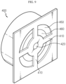
- the ventilation unit 400 is installed on one longitudinal side of the module cover 300, and the ventilation units 400 installed at the pair of module covers 300 are located at opposite sides.
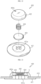
- the ventilation unit 400 includes a perforation hole H, a valve support 410, a one-way venting valve 420, a first hole sealing portion 450 and a second hole sealing portion 460.
- the perforation hole H is formed through one longitudinal side of the module cover 300, and functions as an air passage for cooling the battery cells 110 located inside the battery module when the battery module is in a normal use state. That is, if the perforation hole H formed at one longitudinal side of the battery module functions as an inlet, the perforation hole H located at the opposite side serves as an outlet.
- the valve support 410 traverses the perforation hole H, and the one-way venting valve 420 is installed at a longitudinal center thereof. That is, the valve support 410 is a component provided for fixing the one-way venting valve.
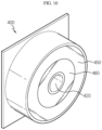
- the one-way venting valve 420 is fixedly installed at the center of the valve support 410 in the longitudinal direction, and when the inner pressure of the battery module rises to a reference pressure or above due to the gas generated by venting of the battery cell 110, the gas is discharged from the inside of the battery module to the outside. That is, the one-way venting valve 420 blocks the introduction of air from the outside of the battery module, and is opened to discharge gas only from the inside to the outside only when the inner pressure increases. Examples of the specific structure of the one-way venting valve 420 will be described in detail later with reference to FIGS. 12 to 16 .
- the first hole sealing portion 450 is attached around an inner wall of the perforation hole H.
- the second hole sealing portion 460 is attached on an outer circumference of the one-way venting valve. According to the invention, the first hole sealing portion 450 and the second hole sealing portion 460 are expanded at the reference temperature or above to meet each other, thereby sealing the perforation hole H.
- the first hole sealing portion 450 and the second hole sealing portion 460 may be made of a sheet containing at least one of an epoxy resin, a butyl resin and a vinyl chloride resin, similar to the case sealing portion 250 described above.
- the materials of the first hole sealing portion 450 and the second hole sealing portion 460 are just examples, and various materials may be applied without limitation as long as they are capable of expanding at a reference temperature or above to seal the perforation hole H.
- the air may not be introduced from the outside of the battery module any longer, and thus the flame does not spread due to a thermal runaway.
- the one-way venting valve 420 is opened to discharge the gas, thereby preventing the battery module from exploding due to the increase in the inner pressure of the battery module.
- the battery module according to an embodiment of the present invention includes the sealing portions 250, 450, 460, which are expanded to seal the battery module when the internal temperature rises, and the one-way venting valve 420, which may discharge gas only from the inside to the outside as the internal pressure increases, it is possible to completely block the introduction of air from the outside in the event of a thermal runaway and quickly discharge the gas therein to the outside, thereby eliminating the risk of ignition/explosion.
- the one-way venting valve 420 may be a unidirectional valve including a lower cap 421 having at least one first flow path 421a, an upper cap 422 having at least one second flow path 422a, a flow path cover 423, and an elastic pressing member 424.
- the upper cap 422 is formed at an upper portion of the lower cap 421 to form an inner space S.
- the flow path cover 423 is located in the inner space S and is elastically pressed from the upper cap 422 toward the lower cap 421 by the elastic pressing member 424 such as a spring to cover the first flow path 421a.
- the flow path cover 423 compresses the elastic pressing member 424 to release the sealed state of the first flow path 421a, and the gas inside the battery module is discharged to the outside of the battery module through the inner space S and the second flow path 422a (see an arrow in FIG. 14 ).
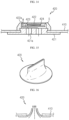
- the one-way venting valve 420 is made of an elastic material such as rubber, and has a funnel shape whose inner space is gradually narrowed outward from the inside of the battery module so that facing surfaces at a top end thereof (referring to an upper end when viewed with reference to FIG. 16 ) are in contact with each other.
- facing surfaces at a top end thereof referring to an upper end when viewed with reference to FIG. 16
- facing surfaces thereof are spaced apart from each other.
- the sealed state of the battery module is released as the top end of the elastic material of the one-way venting valve 420 is opened, and the gas inside the battery module is discharged to the outside along an arrow depicted in FIG. 16 .
Landscapes
- Chemical & Material Sciences (AREA)
- Chemical Kinetics & Catalysis (AREA)
- Electrochemistry (AREA)
- General Chemical & Material Sciences (AREA)
- Engineering & Computer Science (AREA)
- Manufacturing & Machinery (AREA)
- Health & Medical Sciences (AREA)
- Public Health (AREA)
- Business, Economics & Management (AREA)
- Emergency Management (AREA)
- Inorganic Chemistry (AREA)
- Battery Mounting, Suspending (AREA)
- Gas Exhaust Devices For Batteries (AREA)
- Secondary Cells (AREA)
Applications Claiming Priority (2)
| Application Number | Priority Date | Filing Date | Title |
|---|---|---|---|
| KR1020190025995A KR102400818B1 (ko) | 2019-03-06 | 2019-03-06 | 열폭주 현상 발생 시 모듈 내부로 공기 유입을 막을 수 있는 구조를 갖는 배터리 모듈 및 이를 포함하는 배터리 팩 |
| PCT/KR2020/003083 WO2020180115A1 (ko) | 2019-03-06 | 2020-03-04 | 열폭주 현상 발생 시 모듈 내부로 공기 유입을 막을 수 있는 구조를 갖는 배터리 모듈 및 이를 포함하는 배터리 팩 |
Publications (3)
| Publication Number | Publication Date |
|---|---|
| EP3836296A1 EP3836296A1 (en) | 2021-06-16 |
| EP3836296A4 EP3836296A4 (en) | 2021-11-10 |
| EP3836296B1 true EP3836296B1 (en) | 2025-01-15 |
Family
ID=72337902
Family Applications (1)
| Application Number | Title | Priority Date | Filing Date |
|---|---|---|---|
| EP20765773.5A Active EP3836296B1 (en) | 2019-03-06 | 2020-03-04 | Battery module having structure capable of preventing inflow of air into module when thermal runaway occurs and battery pack including same |
Country Status (9)
| Country | Link |
|---|---|
| US (1) | US11462801B2 (pl) |
| EP (1) | EP3836296B1 (pl) |
| JP (1) | JP7105919B2 (pl) |
| KR (1) | KR102400818B1 (pl) |
| CN (1) | CN112335097B (pl) |
| ES (1) | ES3009699T3 (pl) |
| HU (1) | HUE070110T2 (pl) |
| PL (1) | PL3836296T3 (pl) |
| WO (1) | WO2020180115A1 (pl) |
Families Citing this family (53)
| Publication number | Priority date | Publication date | Assignee | Title |
|---|---|---|---|---|
| US11374284B2 (en) * | 2019-12-13 | 2022-06-28 | Proterra Operating Company, Inc. | Battery vent system |
| KR20220037195A (ko) * | 2020-09-17 | 2022-03-24 | 에스케이온 주식회사 | 배터리 팩 |
| KR102590339B1 (ko) | 2020-10-19 | 2023-10-17 | 지앙수 컨템포러리 엠퍼렉스 테크놀로지 리미티드 | 전지 박스 본체, 전지, 전기 장치, 전지 제조 방법 및 장치 |
| KR102625181B1 (ko) * | 2020-11-17 | 2024-01-16 | 지앙수 컨템포러리 엠퍼렉스 테크놀로지 리미티드 | 소방 장치, 케이스 어셈블리, 배터리, 전기 장치 및 배터리의 제조 방법 |
| DE102021103378B3 (de) * | 2021-02-12 | 2022-01-20 | Bayerische Motoren Werke Aktiengesellschaft | Traktionsbatterie mit Entgasungskollektor sowie Kraftfahrzeug |
| KR102892927B1 (ko) * | 2021-02-22 | 2025-11-27 | 주식회사 엘지에너지솔루션 | 전지 모듈 및 이를 포함하는 전지 팩 |
| KR20220129323A (ko) * | 2021-03-16 | 2022-09-23 | 주식회사 엘지에너지솔루션 | 전지 모듈 및 이를 포함하는 전지팩 |
| JP7258075B2 (ja) * | 2021-04-27 | 2023-04-14 | プライムプラネットエナジー&ソリューションズ株式会社 | ラミネート型電池モジュール |
| KR20220165133A (ko) * | 2021-06-07 | 2022-12-14 | 주식회사 엘지에너지솔루션 | 배터리 모듈, 이를 포함하는 배터리 팩 및 자동차 |
| KR102861602B1 (ko) * | 2021-06-21 | 2025-09-17 | 주식회사 엘지에너지솔루션 | 전지 모듈 및 이를 포함하는 전지 팩 |
| US20230026302A1 (en) * | 2021-07-20 | 2023-01-26 | Rivian Ip Holdings, Llc | Battery pack venting |
| US20240222784A1 (en) * | 2021-08-12 | 2024-07-04 | Lg Energy Solution, Ltd. | Battery module with reinforced safety |
| US20240063491A1 (en) * | 2021-08-17 | 2024-02-22 | Lg Energy Solution, Ltd. | Battery pack and device including the same |
| KR102876311B1 (ko) * | 2021-11-03 | 2025-10-23 | 주식회사 엘지에너지솔루션 | 전지 팩 및 이를 포함하는 디바이스 |
| CN216488385U (zh) * | 2021-11-05 | 2022-05-10 | 宁德时代新能源科技股份有限公司 | 一种定向排气装置、电池及储能预制仓 |
| KR20230093108A (ko) | 2021-12-17 | 2023-06-27 | 현대자동차주식회사 | 차량의 배터리팩 마운팅 구조 |
| CN221176561U (zh) * | 2021-12-27 | 2024-06-18 | 株式会社Lg新能源 | 电池组以及包括该电池组的能量存储系统和车辆 |
| US12278390B2 (en) | 2022-02-03 | 2025-04-15 | Caterpillar Inc. | Pressure release vent for battery module |
| KR102663656B1 (ko) | 2022-02-04 | 2024-05-07 | 현대자동차주식회사 | 차량의 배터리 냉각 구조 |
| WO2023157999A1 (ko) | 2022-02-21 | 2023-08-24 | 에프엠에스 주식회사 | 배터리 팩용 벤팅 디바이스 |
| WO2023195716A1 (ko) * | 2022-04-06 | 2023-10-12 | 주식회사 엘지에너지솔루션 | 배터리 팩 |
| KR102649356B1 (ko) * | 2022-04-15 | 2024-03-19 | 주식회사 엘지에너지솔루션 | 안전성이 강화된 배터리 모듈 |
| CN114497814B (zh) * | 2022-04-18 | 2022-07-01 | 深圳市尚亿芯科技有限公司 | 一种具有自动灭火防爆功能的锂电池电池箱 |
| CN115000611B (zh) * | 2022-05-06 | 2024-06-14 | 摩登汽车有限公司 | 动力电池总成 |
| SE546645C2 (en) * | 2022-07-13 | 2025-01-07 | Northvolt Ab | Top lid venting battery module |
| KR102528689B1 (ko) | 2022-10-14 | 2023-05-04 | 에프엠에스 주식회사 | 배터리 팩용 벤팅디바이스 |
| KR102879058B1 (ko) * | 2022-12-08 | 2025-11-06 | 주식회사 엔티엠 | 배터리케이스용 통기성 확보 장치 |
| WO2024219702A2 (ko) * | 2023-04-18 | 2024-10-24 | 주식회사 엘지에너지솔루션 | 배터리 모듈 |
| CN116505185B (zh) * | 2023-06-27 | 2023-10-03 | 楚能新能源股份有限公司 | 浸默阀总成和具有其的浸默式二次电池装置 |
| KR20250027340A (ko) | 2023-08-16 | 2025-02-26 | 주식회사 엘지화학 | 경화성 수지 조성물 |
| CN121548614A (zh) | 2023-08-16 | 2026-02-17 | 株式会社Lg化学 | 吸热垫 |
| KR102834885B1 (ko) | 2023-08-16 | 2025-07-16 | 주식회사 엘지화학 | 흡열 패드 |
| KR20250026068A (ko) | 2023-08-16 | 2025-02-25 | 주식회사 엘지화학 | 수지 조성물 |
| KR102787409B1 (ko) | 2023-08-16 | 2025-03-28 | 주식회사 엘지화학 | 수지 조성물 |
| KR20250026061A (ko) | 2023-08-16 | 2025-02-25 | 주식회사 엘지화학 | 수지 조성물 |
| WO2025037920A1 (ko) | 2023-08-16 | 2025-02-20 | 주식회사 엘지화학 | 수지 조성물 |
| KR20250027341A (ko) | 2023-08-16 | 2025-02-26 | 주식회사 엘지화학 | 다층 흡열 패드 |
| KR102691409B1 (ko) | 2023-08-16 | 2024-08-05 | 주식회사 엘지화학 | 흡열 패드 |
| KR20250026062A (ko) | 2023-08-16 | 2025-02-25 | 주식회사 엘지화학 | 수지 조성물 |
| KR102775908B1 (ko) | 2023-08-16 | 2025-03-06 | 주식회사 엘지화학 | 흡열 패드 |
| KR20250026066A (ko) | 2023-08-16 | 2025-02-25 | 주식회사 엘지화학 | 수지 조성물 |
| KR102718283B1 (ko) | 2023-08-16 | 2024-10-18 | 주식회사 엘지화학 | 수지 조성물 |
| KR20250026064A (ko) | 2023-08-16 | 2025-02-25 | 주식회사 엘지화학 | 흡열 패드 |
| CN121548613A (zh) | 2023-08-16 | 2026-02-17 | 株式会社Lg化学 | 吸热垫 |
| KR20250027342A (ko) | 2023-08-16 | 2025-02-26 | 주식회사 엘지화학 | 다층 흡열 패드 |
| KR20250027339A (ko) | 2023-08-16 | 2025-02-26 | 주식회사 엘지화학 | 경화성 수지 조성물 |
| TWI879522B (zh) * | 2023-12-21 | 2025-04-01 | 台達電子工業股份有限公司 | 電池模組滅火結構 |
| KR20250149537A (ko) | 2024-04-09 | 2025-10-16 | 주식회사 엘지화학 | 흡열 패드 |
| KR20250176036A (ko) | 2024-06-11 | 2025-12-18 | 주식회사 엘지화학 | 다층 흡열 패드 |
| KR20260001843A (ko) | 2024-06-28 | 2026-01-06 | 주식회사 엘지화학 | 흡열 패드 |
| KR20260002274A (ko) | 2024-06-28 | 2026-01-06 | 주식회사 엘지화학 | 흡열 패드 |
| WO2026005551A1 (ko) | 2024-06-28 | 2026-01-02 | 주식회사 엘지화학 | 다층 흡열 패드 |
| KR102834884B1 (ko) | 2024-09-25 | 2025-07-18 | 주식회사 엘지화학 | 흡열 패드 |
Family Cites Families (20)
| Publication number | Priority date | Publication date | Assignee | Title |
|---|---|---|---|---|
| KR100369068B1 (ko) | 1999-04-16 | 2003-01-24 | 삼성에스디아이 주식회사 | 원통형 2차 전지 |
| DE10113371A1 (de) | 2001-03-20 | 2002-10-02 | Guenter Schulte | Brandschutzventil für eine Rohrleitung |
| JP4929540B2 (ja) | 2001-07-10 | 2012-05-09 | 株式会社デンソー | 非水電解液二次電池 |
| JP2006253020A (ja) | 2005-03-11 | 2006-09-21 | Toshiba Fuel Cell Power Systems Corp | 燃料電池発電装置及び吸排気装置 |
| CN201221627Y (zh) * | 2008-07-04 | 2009-04-15 | 厦门信源环保科技有限公司 | 单向通气簧片阀 |
| KR101179364B1 (ko) | 2008-09-22 | 2012-09-03 | 파나소닉 주식회사 | 휴대전자기기 |
| KR101294169B1 (ko) | 2011-09-26 | 2013-08-08 | 기아자동차주식회사 | 전기자동차용 배터리팩 화재 방지기구 |
| JP2015518638A (ja) | 2012-04-24 | 2015-07-02 | ファルメット オートモーティブ オイ | 防火剤を備えるバッテリーパック |
| JP5993209B2 (ja) | 2012-05-24 | 2016-09-14 | タイガースポリマー株式会社 | 電池冷却構造 |
| JP2015153616A (ja) | 2014-02-14 | 2015-08-24 | 株式会社オートネットワーク技術研究所 | バッテリパック |
| US9685645B2 (en) * | 2014-07-16 | 2017-06-20 | Ford Global Technologies, Llc | Battery pack venting system for electrified vehicle |
| KR20170010531A (ko) | 2015-07-20 | 2017-02-01 | 현대자동차주식회사 | 배터리 모듈 |
| KR20170032034A (ko) * | 2015-09-14 | 2017-03-22 | 삼성에스디아이 주식회사 | 배터리 팩 |
| US20190184306A1 (en) | 2016-08-03 | 2019-06-20 | Clariant International Ltd | Method for recovering titanium (halo) alkoxide from a waste liquid |
| CN206478269U (zh) * | 2016-08-24 | 2017-09-08 | 浙江虹达特种橡胶制品有限公司 | 一种蓄电池防爆阀 |
| KR101917279B1 (ko) | 2017-01-17 | 2018-11-14 | 주식회사 피플웍스 | 온도 제어 기능을 갖는 배터리 팩 |
| KR101780775B1 (ko) * | 2017-03-17 | 2017-10-10 | 주식회사 광운기술 | 점검 및 유지보수가 용이한 케이블 트레이용 차열 차염 부재 |
| KR102348076B1 (ko) * | 2017-06-30 | 2022-01-10 | 에스케이온 주식회사 | 이차 전지 |
| CN208311004U (zh) * | 2018-06-22 | 2019-01-01 | 江苏梅花机械有限公司 | 一种汽车真空泵单向阀 |
| EP3644402B1 (de) * | 2018-10-25 | 2021-04-07 | tmax Holding GmbH | Batteriegehäuse umfassend ein ventil zum druckausgleich und/oder drucküberlastabbau |
-
2019
- 2019-03-06 KR KR1020190025995A patent/KR102400818B1/ko active Active
-
2020
- 2020-03-04 HU HUE20765773A patent/HUE070110T2/hu unknown
- 2020-03-04 ES ES20765773T patent/ES3009699T3/es active Active
- 2020-03-04 US US17/051,270 patent/US11462801B2/en active Active
- 2020-03-04 PL PL20765773.5T patent/PL3836296T3/pl unknown
- 2020-03-04 JP JP2020563490A patent/JP7105919B2/ja active Active
- 2020-03-04 EP EP20765773.5A patent/EP3836296B1/en active Active
- 2020-03-04 WO PCT/KR2020/003083 patent/WO2020180115A1/ko not_active Ceased
- 2020-03-04 CN CN202080003311.7A patent/CN112335097B/zh active Active
Also Published As
| Publication number | Publication date |
|---|---|
| WO2020180115A1 (ko) | 2020-09-10 |
| EP3836296A4 (en) | 2021-11-10 |
| JP7105919B2 (ja) | 2022-07-25 |
| KR20200107214A (ko) | 2020-09-16 |
| CN112335097A (zh) | 2021-02-05 |
| PL3836296T3 (pl) | 2025-03-24 |
| CN112335097B (zh) | 2024-06-18 |
| US11462801B2 (en) | 2022-10-04 |
| JP2021523528A (ja) | 2021-09-02 |
| US20210050573A1 (en) | 2021-02-18 |
| HUE070110T2 (hu) | 2025-05-28 |
| ES3009699T3 (en) | 2025-03-31 |
| EP3836296A1 (en) | 2021-06-16 |
| KR102400818B1 (ko) | 2022-05-20 |
Similar Documents
| Publication | Publication Date | Title |
|---|---|---|
| EP3836296B1 (en) | Battery module having structure capable of preventing inflow of air into module when thermal runaway occurs and battery pack including same | |
| KR102861602B1 (ko) | 전지 모듈 및 이를 포함하는 전지 팩 | |
| EP3133668B1 (en) | Battery module and battery pack including same | |
| KR101954043B1 (ko) | 배터리 팩의 압력 개방 기구 | |
| KR102318043B1 (ko) | 이차전지 및 이를 포함하는 배터리 모듈 | |
| EP4145610B1 (en) | Battery module and battery pack comprising same | |
| CN111668409A (zh) | 电池托盘、动力电池包及车辆 | |
| CN220253415U (zh) | 电池模块和包括该电池模块的电池组 | |
| KR102566979B1 (ko) | 이차전지 및 그 이차전지를 포함하는 전지 팩 | |
| KR102066701B1 (ko) | 냉각 성능이 개선된 배터리 팩의 케이스 구조 | |
| KR101795705B1 (ko) | 파우치형 이차전지용 카트리지 | |
| KR102322910B1 (ko) | 배터리 케이스와 이를 포함하는 배터리 팩 및 자동차 | |
| KR20240084332A (ko) | 유도 벤팅구조를 구비한 배터리 팩 | |
| KR101793435B1 (ko) | 리튬 이차전지 | |
| CN115803950B (zh) | 电池模块和包括该电池模块的电池组 | |
| EP4261999B1 (en) | Battery module having improved airtightness and heat resistance of module case | |
| KR20240101327A (ko) | 배터리 팩 및 이를 포함하는 자동차 | |
| KR20250024418A (ko) | 배터리 모듈 및 이를 포함하는 배터리 팩 |
Legal Events
| Date | Code | Title | Description |
|---|---|---|---|
| STAA | Information on the status of an ep patent application or granted ep patent |
Free format text: STATUS: THE INTERNATIONAL PUBLICATION HAS BEEN MADE |
|
| PUAI | Public reference made under article 153(3) epc to a published international application that has entered the european phase |
Free format text: ORIGINAL CODE: 0009012 |
|
| STAA | Information on the status of an ep patent application or granted ep patent |
Free format text: STATUS: REQUEST FOR EXAMINATION WAS MADE |
|
| 17P | Request for examination filed |
Effective date: 20210308 |
|
| AK | Designated contracting states |
Kind code of ref document: A1 Designated state(s): AL AT BE BG CH CY CZ DE DK EE ES FI FR GB GR HR HU IE IS IT LI LT LU LV MC MK MT NL NO PL PT RO RS SE SI SK SM TR |
|
| REG | Reference to a national code |
Ref country code: DE Ref legal event code: R079 Free format text: PREVIOUS MAIN CLASS: H01M0010658000 Ipc: H01M0010613000 Ref country code: DE Ref legal event code: R079 Ref document number: 602020044834 Country of ref document: DE Free format text: PREVIOUS MAIN CLASS: H01M0010658000 Ipc: H01M0010613000 |
|
| A4 | Supplementary search report drawn up and despatched |
Effective date: 20211012 |
|
| RIC1 | Information provided on ipc code assigned before grant |
Ipc: H01M 50/325 20210101ALI20211006BHEP Ipc: H01M 50/375 20210101ALI20211006BHEP Ipc: H01M 50/383 20210101ALI20211006BHEP Ipc: H01M 50/209 20210101ALI20211006BHEP Ipc: H01M 10/6563 20140101ALI20211006BHEP Ipc: H01M 10/613 20140101AFI20211006BHEP |
|
| RAP1 | Party data changed (applicant data changed or rights of an application transferred) |
Owner name: LG ENERGY SOLUTION LTD. |
|
| RAP3 | Party data changed (applicant data changed or rights of an application transferred) |
Owner name: LG ENERGY SOLUTION, LTD. |
|
| DAV | Request for validation of the european patent (deleted) | ||
| DAX | Request for extension of the european patent (deleted) | ||
| GRAP | Despatch of communication of intention to grant a patent |
Free format text: ORIGINAL CODE: EPIDOSNIGR1 |
|
| STAA | Information on the status of an ep patent application or granted ep patent |
Free format text: STATUS: GRANT OF PATENT IS INTENDED |
|
| INTG | Intention to grant announced |
Effective date: 20240821 |
|
| P01 | Opt-out of the competence of the unified patent court (upc) registered |
Free format text: CASE NUMBER: APP_49816/2024 Effective date: 20240903 |
|
| GRAS | Grant fee paid |
Free format text: ORIGINAL CODE: EPIDOSNIGR3 |
|
| GRAA | (expected) grant |
Free format text: ORIGINAL CODE: 0009210 |
|
| STAA | Information on the status of an ep patent application or granted ep patent |
Free format text: STATUS: THE PATENT HAS BEEN GRANTED |
|
| AK | Designated contracting states |
Kind code of ref document: B1 Designated state(s): AL AT BE BG CH CY CZ DE DK EE ES FI FR GB GR HR HU IE IS IT LI LT LU LV MC MK MT NL NO PL PT RO RS SE SI SK SM TR |
|
| REG | Reference to a national code |
Ref country code: CH Ref legal event code: EP Ref country code: GB Ref legal event code: FG4D |
|
| REG | Reference to a national code |
Ref country code: DE Ref legal event code: R096 Ref document number: 602020044834 Country of ref document: DE |
|
| REG | Reference to a national code |
Ref country code: IE Ref legal event code: FG4D |
|
| REG | Reference to a national code |
Ref country code: SE Ref legal event code: TRGR |
|
| REG | Reference to a national code |
Ref country code: ES Ref legal event code: FG2A Ref document number: 3009699 Country of ref document: ES Kind code of ref document: T3 Effective date: 20250331 |
|
| PGFP | Annual fee paid to national office [announced via postgrant information from national office to epo] |
Ref country code: PL Payment date: 20250224 Year of fee payment: 6 |
|
| REG | Reference to a national code |
Ref country code: NL Ref legal event code: MP Effective date: 20250115 |
|
| REG | Reference to a national code |
Ref country code: HU Ref legal event code: AG4A Ref document number: E070110 Country of ref document: HU |
|
| PG25 | Lapsed in a contracting state [announced via postgrant information from national office to epo] |
Ref country code: NL Free format text: LAPSE BECAUSE OF FAILURE TO SUBMIT A TRANSLATION OF THE DESCRIPTION OR TO PAY THE FEE WITHIN THE PRESCRIBED TIME-LIMIT Effective date: 20250115 |
|
| PG25 | Lapsed in a contracting state [announced via postgrant information from national office to epo] |
Ref country code: RS Free format text: LAPSE BECAUSE OF FAILURE TO SUBMIT A TRANSLATION OF THE DESCRIPTION OR TO PAY THE FEE WITHIN THE PRESCRIBED TIME-LIMIT Effective date: 20250415 |
|
| PG25 | Lapsed in a contracting state [announced via postgrant information from national office to epo] |
Ref country code: FI Free format text: LAPSE BECAUSE OF FAILURE TO SUBMIT A TRANSLATION OF THE DESCRIPTION OR TO PAY THE FEE WITHIN THE PRESCRIBED TIME-LIMIT Effective date: 20250115 |
|
| PGFP | Annual fee paid to national office [announced via postgrant information from national office to epo] |
Ref country code: ES Payment date: 20250408 Year of fee payment: 6 |
|
| REG | Reference to a national code |
Ref country code: LT Ref legal event code: MG9D |
|
| PG25 | Lapsed in a contracting state [announced via postgrant information from national office to epo] |
Ref country code: IS Free format text: LAPSE BECAUSE OF FAILURE TO SUBMIT A TRANSLATION OF THE DESCRIPTION OR TO PAY THE FEE WITHIN THE PRESCRIBED TIME-LIMIT Effective date: 20250515 Ref country code: NO Free format text: LAPSE BECAUSE OF FAILURE TO SUBMIT A TRANSLATION OF THE DESCRIPTION OR TO PAY THE FEE WITHIN THE PRESCRIBED TIME-LIMIT Effective date: 20250415 |
|
| REG | Reference to a national code |
Ref country code: AT Ref legal event code: MK05 Ref document number: 1760436 Country of ref document: AT Kind code of ref document: T Effective date: 20250115 |
|
| PG25 | Lapsed in a contracting state [announced via postgrant information from national office to epo] |
Ref country code: HR Free format text: LAPSE BECAUSE OF FAILURE TO SUBMIT A TRANSLATION OF THE DESCRIPTION OR TO PAY THE FEE WITHIN THE PRESCRIBED TIME-LIMIT Effective date: 20250115 |
|
| PG25 | Lapsed in a contracting state [announced via postgrant information from national office to epo] |
Ref country code: LV Free format text: LAPSE BECAUSE OF FAILURE TO SUBMIT A TRANSLATION OF THE DESCRIPTION OR TO PAY THE FEE WITHIN THE PRESCRIBED TIME-LIMIT Effective date: 20250115 Ref country code: PT Free format text: LAPSE BECAUSE OF FAILURE TO SUBMIT A TRANSLATION OF THE DESCRIPTION OR TO PAY THE FEE WITHIN THE PRESCRIBED TIME-LIMIT Effective date: 20250515 |
|
| PG25 | Lapsed in a contracting state [announced via postgrant information from national office to epo] |
Ref country code: GR Free format text: LAPSE BECAUSE OF FAILURE TO SUBMIT A TRANSLATION OF THE DESCRIPTION OR TO PAY THE FEE WITHIN THE PRESCRIBED TIME-LIMIT Effective date: 20250416 Ref country code: BG Free format text: LAPSE BECAUSE OF FAILURE TO SUBMIT A TRANSLATION OF THE DESCRIPTION OR TO PAY THE FEE WITHIN THE PRESCRIBED TIME-LIMIT Effective date: 20250115 |
|
| PG25 | Lapsed in a contracting state [announced via postgrant information from national office to epo] |
Ref country code: AT Free format text: LAPSE BECAUSE OF FAILURE TO SUBMIT A TRANSLATION OF THE DESCRIPTION OR TO PAY THE FEE WITHIN THE PRESCRIBED TIME-LIMIT Effective date: 20250115 |
|
| PG25 | Lapsed in a contracting state [announced via postgrant information from national office to epo] |
Ref country code: SM Free format text: LAPSE BECAUSE OF FAILURE TO SUBMIT A TRANSLATION OF THE DESCRIPTION OR TO PAY THE FEE WITHIN THE PRESCRIBED TIME-LIMIT Effective date: 20250115 |
|
| PG25 | Lapsed in a contracting state [announced via postgrant information from national office to epo] |
Ref country code: DK Free format text: LAPSE BECAUSE OF FAILURE TO SUBMIT A TRANSLATION OF THE DESCRIPTION OR TO PAY THE FEE WITHIN THE PRESCRIBED TIME-LIMIT Effective date: 20250115 |
|
| PG25 | Lapsed in a contracting state [announced via postgrant information from national office to epo] |
Ref country code: MC Free format text: LAPSE BECAUSE OF FAILURE TO SUBMIT A TRANSLATION OF THE DESCRIPTION OR TO PAY THE FEE WITHIN THE PRESCRIBED TIME-LIMIT Effective date: 20250115 |
|
| PG25 | Lapsed in a contracting state [announced via postgrant information from national office to epo] |
Ref country code: IT Free format text: LAPSE BECAUSE OF FAILURE TO SUBMIT A TRANSLATION OF THE DESCRIPTION OR TO PAY THE FEE WITHIN THE PRESCRIBED TIME-LIMIT Effective date: 20250115 |
|
| REG | Reference to a national code |
Ref country code: DE Ref legal event code: R097 Ref document number: 602020044834 Country of ref document: DE |
|
| PG25 | Lapsed in a contracting state [announced via postgrant information from national office to epo] |
Ref country code: EE Free format text: LAPSE BECAUSE OF FAILURE TO SUBMIT A TRANSLATION OF THE DESCRIPTION OR TO PAY THE FEE WITHIN THE PRESCRIBED TIME-LIMIT Effective date: 20250115 Ref country code: CZ Free format text: LAPSE BECAUSE OF FAILURE TO SUBMIT A TRANSLATION OF THE DESCRIPTION OR TO PAY THE FEE WITHIN THE PRESCRIBED TIME-LIMIT Effective date: 20250115 |
|
| PG25 | Lapsed in a contracting state [announced via postgrant information from national office to epo] |
Ref country code: RO Free format text: LAPSE BECAUSE OF FAILURE TO SUBMIT A TRANSLATION OF THE DESCRIPTION OR TO PAY THE FEE WITHIN THE PRESCRIBED TIME-LIMIT Effective date: 20250115 |
|
| REG | Reference to a national code |
Ref country code: CH Ref legal event code: H13 Free format text: ST27 STATUS EVENT CODE: U-0-0-H10-H13 (AS PROVIDED BY THE NATIONAL OFFICE) Effective date: 20251024 |
|
| PG25 | Lapsed in a contracting state [announced via postgrant information from national office to epo] |
Ref country code: SK Free format text: LAPSE BECAUSE OF FAILURE TO SUBMIT A TRANSLATION OF THE DESCRIPTION OR TO PAY THE FEE WITHIN THE PRESCRIBED TIME-LIMIT Effective date: 20250115 |
|
| PG25 | Lapsed in a contracting state [announced via postgrant information from national office to epo] |
Ref country code: LU Free format text: LAPSE BECAUSE OF NON-PAYMENT OF DUE FEES Effective date: 20250304 |
|
| PLBE | No opposition filed within time limit |
Free format text: ORIGINAL CODE: 0009261 |
|
| STAA | Information on the status of an ep patent application or granted ep patent |
Free format text: STATUS: NO OPPOSITION FILED WITHIN TIME LIMIT |
|
| 26N | No opposition filed |
Effective date: 20251016 |
|
| PG25 | Lapsed in a contracting state [announced via postgrant information from national office to epo] |
Ref country code: CH Free format text: LAPSE BECAUSE OF NON-PAYMENT OF DUE FEES Effective date: 20250331 |
|
| PG25 | Lapsed in a contracting state [announced via postgrant information from national office to epo] |
Ref country code: IE Free format text: LAPSE BECAUSE OF NON-PAYMENT OF DUE FEES Effective date: 20250304 |
|
| PGFP | Annual fee paid to national office [announced via postgrant information from national office to epo] |
Ref country code: SE Payment date: 20260223 Year of fee payment: 7 |
|
| PGFP | Annual fee paid to national office [announced via postgrant information from national office to epo] |
Ref country code: GB Payment date: 20260224 Year of fee payment: 7 |
|
| PGFP | Annual fee paid to national office [announced via postgrant information from national office to epo] |
Ref country code: DE Payment date: 20260220 Year of fee payment: 7 |
|
| PGFP | Annual fee paid to national office [announced via postgrant information from national office to epo] |
Ref country code: BE Payment date: 20260220 Year of fee payment: 7 |
|
| PGFP | Annual fee paid to national office [announced via postgrant information from national office to epo] |
Ref country code: HU Payment date: 20260310 Year of fee payment: 7 |
|
| PGFP | Annual fee paid to national office [announced via postgrant information from national office to epo] |
Ref country code: FR Payment date: 20260224 Year of fee payment: 7 |