EP3834973B1 - Bohrwerkzeug - Google Patents
Bohrwerkzeug Download PDFInfo
- Publication number
- EP3834973B1 EP3834973B1 EP20211588.7A EP20211588A EP3834973B1 EP 3834973 B1 EP3834973 B1 EP 3834973B1 EP 20211588 A EP20211588 A EP 20211588A EP 3834973 B1 EP3834973 B1 EP 3834973B1
- Authority
- EP
- European Patent Office
- Prior art keywords
- drilling tool
- main body
- end portion
- cutting
- base end
- Prior art date
- Legal status (The legal status is an assumption and is not a legal conclusion. Google has not performed a legal analysis and makes no representation as to the accuracy of the status listed.)
- Active
Links
Images






Classifications
-
- B—PERFORMING OPERATIONS; TRANSPORTING
- B23—MACHINE TOOLS; METAL-WORKING NOT OTHERWISE PROVIDED FOR
- B23B—TURNING; BORING
- B23B51/00—Tools for drilling machines
- B23B51/06—Drills with lubricating or cooling equipment
-
- B—PERFORMING OPERATIONS; TRANSPORTING
- B23—MACHINE TOOLS; METAL-WORKING NOT OTHERWISE PROVIDED FOR
- B23B—TURNING; BORING
- B23B51/00—Tools for drilling machines
- B23B51/04—Drills for trepanning
- B23B51/0486—Drills for trepanning with lubricating or cooling equipment
- B23B51/0493—Drills for trepanning with lubricating or cooling equipment with exchangeable cutting inserts, e.g. able to be clamped
-
- B—PERFORMING OPERATIONS; TRANSPORTING
- B23—MACHINE TOOLS; METAL-WORKING NOT OTHERWISE PROVIDED FOR
- B23B—TURNING; BORING
- B23B51/00—Tools for drilling machines
-
- B—PERFORMING OPERATIONS; TRANSPORTING
- B23—MACHINE TOOLS; METAL-WORKING NOT OTHERWISE PROVIDED FOR
- B23B—TURNING; BORING
- B23B2270/00—Details of turning, boring or drilling machines, processes or tools not otherwise provided for
- B23B2270/30—Chip guiding or removal
-
- B—PERFORMING OPERATIONS; TRANSPORTING
- B23—MACHINE TOOLS; METAL-WORKING NOT OTHERWISE PROVIDED FOR
- B23B—TURNING; BORING
- B23B27/00—Tools for turning or boring machines; Tools of a similar kind in general; Accessories therefor
- B23B27/14—Cutting tools of which the bits or tips or cutting inserts are of special material
- B23B27/16—Cutting tools of which the bits or tips or cutting inserts are of special material with exchangeable cutting bits or cutting inserts, e.g. able to be clamped
-
- B—PERFORMING OPERATIONS; TRANSPORTING
- B23—MACHINE TOOLS; METAL-WORKING NOT OTHERWISE PROVIDED FOR
- B23B—TURNING; BORING
- B23B51/00—Tools for drilling machines
- B23B51/06—Drills with lubricating or cooling equipment
- B23B51/063—Deep hole drills, e.g. ejector drills
Definitions
- the disclosure relates to a drilling tool.
- Tools for drilling processing conventionally use an indexable drill or the like (for example, WO 2001/98008 ) which provides a helical groove on a side surface of the main body to allow the chip to be discharged out via the hole.
- an indexable drill or the like for example, WO 2001/98008
- tools for deep hole drilling process are used in so-called BTA (Boring & Trepanning Association) method, wherein the cutting oil is fed from the outside and the chip is discharged from the inside.
- BTA Biting & Trepanning Association
- Such method usually utilizes, for example, a special tool or apparatus having the following structure: a drill head is screwed into a drill tube, and cutting oil, which is fed between the drill tube and the hole to be processed to the cutter head, is discharged out of the drill tube together with the chip.
- Such tool or apparatus is designed to have large quantity of cutting oil to allow the chip to be discharged out of the tube. It utilizes cylindrical tube shape without the need of chip pocket, thereby easily obtaining high rigidity. Furthermore, compared with the gun drill machine, it has improved processing performance.
- WO2019/087656A1 which discloses the preamble of claim 1, is considered as the closest prior art document.
- the tool or apparatus according to the BTA method as mentioned above has special complicated structure with high cost.
- general drilling tools or equipment do not provide a structure which allows the cutting to be performed simultaneously with the feeding (supplying) of a large quantity of cutting oil.
- they can hardly efficiently discharge chips by utilizing the cutting oil, as in the BTA method, simultaneously when the cutting is performed.
- no concept or technique has been found to efficiently discharge chips by utilizing the cutting oil simultaneously with the cutting, as in the BTA method, with the use of general drilling tools or equipment.
- the purpose of the present disclosure is to provide a drilling tool according to claim 1 with improved structure to improve chips discharging performance.
- the drilling tool comprises: a cutting insert, the cutting insert has a cutting edge at the front end portion; and a main body, the main body is mounted with the cutting insert, the drilling tool comprises a hollow discharge channel formed inside the main body, and the discharge channel has a curved surface for guiding the chip in a direction towards the base end portion opposite to the front end portion.
- a force acting to guide chips in a direction towards the base end portion can be applied by the curved surface of the discharge channel during rotation of the tool, thus improving chips discharging performance.
- general drilling tools or equipment can be used, instead of special complicated structure as the BTA method, to efficiently discharge chips simultaneously with the drilling, as in the BTA method.
- the above mentioned drilling tool which comprises a hollow discharge channel formed inside the main body, can discharge the fed cutting oil and the chip by the discharge channel simultaneously with the drilling.
- the discharge channel is formed between the rotation axis of the drilling tool and the outer circumferential surface.
- the curved surface is an inclined surface configured to apply pushing (accelerating) force on chips in a direction towards the base end portion during rotation of the drilling tool.
- the curved surface is formed with a helical shape around the rotation axis of the drilling tool.
- the curved surface may have a concaved shape in the cross section perpendicular to the rotation axis.
- a plurality of cutting inserts are provided, and a number of (same as the number of the cutting insert) discharge channels are provided, corresponding to respective cutting inserts, and formed to extend from the front end portion to the base end portion and converge with each other during extending.
- a plurality of discharge channels are provided, which are axisymmetrical (rotational symmetrical) about the rotation axis of the drilling tool as a center.
- a supporting member is further provided.
- the supporting member is mounted on the base end portion of the main body to support the main body, and is provided with a hollow flow channel in communication with the discharge channel of the main body.
- a cutting oil feed (providing or supplying) passage for feeding cutting oil is further provided.
- the cutting oil feed passage may comprise a cutting oil guiding groove formed on the peripheral surface of the main body.
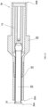
- a drilling tool 1 includes five members: a main body 10, an inner sleeve member 20, an outer sleeve member 30, a bush 40, and a body cover 50.
- the drilling tool 1 is configured to rotate about the rotation axis 1C as a center, to drill the work material.
- Cutting inserts 60 with cutting edges 62 are mounted at a front end portion 1A of the drilling tool 1 (see FIG.1 , etc.).
- An outer circumferential surface 1D including both a cylindrical surface and a circular conical surface, is formed between a base end portion 1B and the front end portion 1A.
- the five members (the main body 10, the inner sleeve member 20, the outer sleeve member 30, the bush 40, and the body cover 50) shown in the figures, as well as the structure of the drilling tool 1, will be described below.
- the main body (the first part) 10 is a bar-shaped component made of metal material and is shaped to extend from a base end 10B to a front end 10A along the rotation axis 1C of the drilling tool 1 (see FIGs.1 and 5 , etc.).
- the rotation axis 1C is an imaginary straight line passing through the center of the main body 10.
- the main body 10 is arranged with at least a discharge channel 12, a mounting base 16, ejection openings 17, and at least a guiding groove 18.
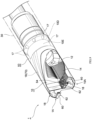
- the discharge channel 12 forms a flow path through which the chip (indicated by symbol S in FIG.5 ), which is produced when the work material is drilled by means of the drilling tool 1, can be discharged.
- the discharge channel 12 having a hollow structure with a curved surface 14 is formed inside of the main body 10.
- the curved surface 14 serves to guide chips S produced at the front end portion 1A of the drilling tool 1 in a direction towards the base end portion 1B.
- the number of discharge channels 12 is not particularly limited.
- a total of two discharge channels 12 are provided, which are helically arranged and are axisymmetrical about the rotation axis 1C in such a manner as to correspond, in a one-to-one manner, to each of the two cutting inserts 60 which are axisymmetrically arranged in the front end portion 1A of the drilling tool 1 (see FIG.5 , etc.).
- discharge channels 12 are formed between the rotation axis 1C and the outer circumferential surface 1D of the drilling tool 1, in such a manner as to enable the chips S to move in a direction towards the base end portion 1B during the rotation for drilling (see FIG.5 , etc.).
- the discharge channel 12 is formed as follows.
- the discharge channel 12 is helical shaped and shaped as right-hand thread, such that it can be rotated, as the drilling tool 1, in a rotating direction (the counterclockwise direction when viewed from the front end portion 1A side, i.e., the direction indicated by symbol R in FIG.1 ) to allow the chip S to move to the base end portion 1B side, and the discharge channel 12 is shaped to be axisymmetrical with the rotation axis 1C as the center (see FIGs.7 and 8 , etc.).
- the pair of discharge channels 12 are formed to extend from the front end 10A to the base end 10B of the main body 10 and converge with each other during extending near the rotation axis 1C (see FIGs.5 and 10 , etc.).
- the shape of the curved surface 14, i.e., the surface of the discharge channel 12, is not particularly limited.
- the curved surface 14 has a concaved shape in the cross section perpendicular to the rotation axis 1C (see FIG.1 , etc.).
- it may have same curvature, or different curvatures varied from one radial (or axial) position to another, or may be appropriately twisted.
- it is shaped in such a manner as to generate a component of force in a direction to effectively guide the chips S from the surface of the curved surface 14 towards the base end portion 1B side during rotation.
- the discharge channel 12 defined by the above-mentioned curved surface (discharge surface) 14 generates the force (a resistance towards a direction perpendicular to the surface) N acting on the chips S from the curved surface 14 which includes a component of force N B towards the base end portion 1B side and the force guiding in a direction towards the base end portion 1B, to improve chips S discharging performance.
- the curved surface 14 of the discharge channel 12 is preferably formed to provide a force which effectively guides the chips S at any position towards the base end portion 1B.
- the mounting base 16 is a base portion for mounting the cutting insert 60.
- the front end 10A of the main body 10 are arranged with two mounting bases 16 (see FIG.5 , etc.) at positions axisymmetrical about the rotation axis 1C, and two cutting inserts 60 are mounted on the two mounting bases 16, respectively.
- the cutting inserts 60 are mounted at predetermined positions on the mounting bases 16 by mounting screws 64.
- the ejection openings 17 are openings for ejecting cutting oil (also serving as the coolant) fed from the base end 40B side of the bush 40.
- the plurality of radial ejection openings 17 for ejecting cutting oil are disposed in the circumferential direction at an equal interval on the circular conical surface of the cone shape of the outer peripheral surface of the main body 10 (indicated by symbol 10D in FIG.5 , etc.) (see FIGs.9 and 13 , etc.).
- a cutting oil feed (supply) passage (indicated by symbol 70 in the figures), which is cylindrical, is formed between the main body 10 and the inner sleeve member 20. The cutting oil fed from the cutting oil feed passage 70 and ejected via the ejection openings 17 can flow through the space around the reduced-diameter portion 10E and flow to the guiding grooves 18.
- the guiding grooves 18 are grooves for feeding the cutting oil ejected via the ejection openings 17 to the front end portion 1A of the drilling tool 1.
- guiding grooves 18, which are helical, are arranged on the outer circumferential surface of the main body 10 (see FIGs.7 , 11 and 12 , etc.).
- the cutting oil feed passage 70 which includes the guiding groove 18 is formed between the body cover 50 and the main body 10. The cutting oil fed from the cutting oil feed passage 70 to front end portion 1A of the drilling tool 1 reverses direction at the bottom of the hole of the work material and then can be discharged out via the discharge channel 12 of the main body 10.
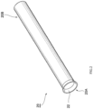
- the inner sleeve member (the second part) 20 is a cylindrical member that mounted on the base end 10B of the main body 10 (see FIGs.1 and 2 , etc.).
- the front end 20A of the inner sleeve member 20 is formed with a tapering enlarged diameter portion 22 (see FIG.2 , etc.).
- the symbol 20B indicates the base end of the inner sleeve member 20.
- the outer sleeve member (the third part) 30 has a greater diameter and a shorter length (a shorter axial length).
- the outer sleeve member (third part) 30 is a cylindrical member that mounted outside the inner sleeve member 20 (see FIG.3 , etc.).
- a feed passage is formed between the outer sleeve member 30 and the inner sleeve member 20, and the feed passage defines a portion of the cutting oil feed passage 70 and has an annular cross section (see FIG.15 ).
- the symbol 30A indicates a front end of the outer sleeve member 30, and the symbol 30B indicates a base end of the outer sleeve member 30.
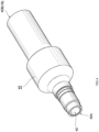
- the bush (the fourth part) 40 is mounted on the base end 10B side of the main body 10 and functions as a supporting member for supporting the main body 10.
- the shape and structure of the bush 40 are not particularly limited.
- the member is designed to have a hollow shape having the hollow flow channel 42 and (see FIG.4 , etc.).
- the hollow flow channel 42 is formed to communicate with the discharge channel 12 of the main body 10 through the inner sleeve member 20 (see FIG. 15 , etc.).
- the symbol 40A indicates a front end of the bush 40
- the symbol 40B indicates a base end of the bush 40.
- the body cover (the fifth part) 50 is a member mounted outside the main body 10.
- the body cover 50 covers a portion of the outer peripheral surface of the main body 10 which includes the circular conical surface 10D, and the cutting oil feed passage 70 is formed between the body cover 50 and the outer circumferential surface of the main body 10 (see FIG.9 , etc.).
- the cutting oil feed passage 70 of the assembled drilling tool 1 is briefly described below (see FIGs.11 and 15 , etc.).
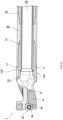
- the cutting oil fed from the base end 40B of the bush 40 may pass through the cutting oil feed passage 70 which is defined by the gap formed between the inner sleeve member 20 and the bush 40, pass through the cutting oil feed passage 70 which is cylindrical and is formed between the main body 10 and the inner sleeve member 20, and may be ejected through the ejection openings 17. Then, it may pass through the space around the reduced-diameter portion 10E and flow to the guiding groove 18, and then pass through the cutting oil feed passage 70 which includes the guiding groove 18. In this way, the cutting oil is fed to the front end portion 1A of the drilling tool 1.
- a force is applied, in a spiral direction, to the cutting oil flowing to the base end portion 1B side.
- an pushing force is applied to facilitate the flow (spiral flow) of the cutting oil, thereby improving the performance of discharging the cutting oil and chip S during rotation (see FIG.5 ).
- Even when such drilling tool 1 is used in an apparatus i.e., the apparatus with poor discharging performance due to a small quantity of cutting oil.
- special devices are usually designed to provide increased quantity of oil flow because the chips cannot be discharged efficiently during cutting when the quantity of oil flow is small) having a structure different from the structure using the BTA method in which the cutting is performed simultaneously with the feeding of a large quantity of cutting oil, the chips S can be sufficiently discharged simultaneously when the drilling process is performed.
- the application range is widened, and the equipment, including low cost equipment, can perform processing with high discharging performance.
- the drilling tool 1 of this embodiment can easily obtain high rigidity. That is, though a hollow member is lighter than a solid member, the hollow member can provide similar rigidity as the solid member of the same size. In another word, even from the viewpoint of lightweight design for the drilling tool 1, the main body 10 with the hollow structure is desired.
- the drilling tool 1 of this embodiment which includes the hollow main body 10 as mentioned above can solve the problem of lack of rigidity relative to the length of the main body.
- the drilling tool 1 as described includes two cutting inserts 60 and two discharge channels 12 in one preferred embodiment.
- a plurality of (more than three) cutting inserts 60 may be provided, and the same number of discharge channels 12 may be provided, corresponding to respective cutting inserts 60, and formed to extend from the front end 10A to the base end 10B of the main body 10 and converge (connecting) with each other during extending from the front end portion 1A to the base end portion 1B.
- the drilling tool 1 (see FIGs.12-14 ), which comprises the flow path for discharging the chips S and the like with an inner diameter decreasing towards the base end portion 1B ( ⁇ A> ⁇ B> ⁇ C), is described for illustration. It is merely a preferred illustrative embodiment.
Landscapes
- Engineering & Computer Science (AREA)
- Mechanical Engineering (AREA)
- Drilling Tools (AREA)
Claims (3)
- Bohrwerkzeug (1), aufweisend:einen Schneideinsatz (60), wobei
der Schneideinsatz (60) eine Schneidkante (62) an einem vorderen Endabschnitt (1A) aufweist;einen Hauptkörper (10), wobei
der Hauptkörper (10) mit dem Schneideinsatz (60) montiert ist;einen hohlen Abfuhrkanal (12), wobeider hohle Abfuhrkanal (12) innerhalb des Hauptkörpers (10) ausgebildet ist, undder hohle Abfuhrkanal (12) eine gekrümmte Fläche (14) aufweist, um einen Chip (S) in einer Richtung zu einem Basisendabschnitt (1B) gegenüber dem vorderen Endabschnitt (1A) hin zu führen,wobei der hohle Abfuhrkanal (12) zwischen einer Drehachse (1C) des Bohrwerkzeugs und der Außenumfangsfläche (1D) ausgebildet ist,wobei die gekrümmte Fläche (14) eine geneigte Fläche ist, die konfiguriert ist, während einer Drehung des Bohrwerkzeugs eine Schubkraft auf den Chip (S) in einer Richtung zu dem Basisendabschnitt (1B) hin aufzubringen,wobei das Bohrwerkzeug mit einer Vielzahl von Schneideinsätzen (60) versehen ist und eine Vielzahl von Abfuhrkanälen (12) ausgebildet sind, um sich von dem vorderen Endabschnitt (1A) zu dem Basisendabschnitt (1B) zu erstrecken, und die Anzahl der Abfuhrkanäle (12) dieselbe ist wie die Anzahl des Schneideinsatzes (60),wobei die Vielzahl von Abfuhrkanälen (12) asymmetrisch um die Drehachse (1C) des Bohrwerkzeugs als Mitte sind,wobei das Bohrwerkzeug ferner ein Stützelement (40) aufweist, wobei das Stützelement (40) an dem Basisendabschnitt (1B) des Hauptkörpers (10) montiert ist und den Hauptkörper (10) stützt und mit einem hohlen Strömungskanal (42) versehen ist, der mit dem Abfuhrkanal (12) des Hauptkörpers (10) in Kommunikation steht,wobei das Bohrwerkzeug ferner einen Schneidölzufuhrdurchgang (70) zur Zufuhr von Schneidöl aufweist;das Bohrwerkzeug dadurch gekennzeichnet ist, dass:die gekrümmte Fläche (14) mit einer Wendelform um die Drehachse (1C) des Bohrwerkzeugs ausgebildet ist, unddass die Abfuhrkanäle (12) während des Erstreckens miteinander verbunden sind. - Bohrwerkzeug nach Anspruch 1, wobei die gekrümmte Fläche (14) in einem Querschnitt senkrecht zu der Drehachse (C1) eine konkave Form aufweist.
- Bohrwerkzeug nach Anspruch 1 oder 2, wobei
der Schneidölzufuhrdurchgang (70) eine Schneidölzufuhrnut (18) aufweist, die auf einer Umfangsfläche des Hauptkörpers (10) ausgebildet ist.
Applications Claiming Priority (1)
| Application Number | Priority Date | Filing Date | Title |
|---|---|---|---|
| JP2019224379A JP6835194B1 (ja) | 2019-12-12 | 2019-12-12 | 穴あけ工具 |
Publications (2)
| Publication Number | Publication Date |
|---|---|
| EP3834973A1 EP3834973A1 (de) | 2021-06-16 |
| EP3834973B1 true EP3834973B1 (de) | 2023-08-23 |
Family
ID=73698663
Family Applications (1)
| Application Number | Title | Priority Date | Filing Date |
|---|---|---|---|
| EP20211588.7A Active EP3834973B1 (de) | 2019-12-12 | 2020-12-03 | Bohrwerkzeug |
Country Status (4)
| Country | Link |
|---|---|
| US (1) | US11433462B2 (de) |
| EP (1) | EP3834973B1 (de) |
| JP (1) | JP6835194B1 (de) |
| CN (1) | CN112974921B (de) |
Families Citing this family (3)
| Publication number | Priority date | Publication date | Assignee | Title |
|---|---|---|---|---|
| JP7250257B1 (ja) * | 2022-08-25 | 2023-04-03 | 株式会社タンガロイ | チップ及び切削工具 |
| JP7569026B1 (ja) * | 2024-04-26 | 2024-10-17 | 株式会社タンガロイ | 穴加工用の切削工具とその工具ボディ |
| JP7839489B1 (ja) * | 2024-10-23 | 2026-04-02 | 株式会社タンガロイ | ボディ及び切削工具 |
Family Cites Families (51)
| Publication number | Priority date | Publication date | Assignee | Title |
|---|---|---|---|---|
| US3094016A (en) * | 1959-11-20 | 1963-06-18 | Kleine Werner Kurt Max | Trepanning and boring head |
| US3816018A (en) * | 1972-10-06 | 1974-06-11 | Tatra Np | Boring bit |
| JPS5041192U (de) * | 1973-08-10 | 1975-04-25 | ||
| JPS59167614U (ja) * | 1983-04-21 | 1984-11-09 | 株式会社日本冶金 | 深穴切削装置 |
| JPH0790405B2 (ja) * | 1988-08-29 | 1995-10-04 | 日立精機株式会社 | 深穴加工方法 |
| WO1991016521A1 (en) * | 1990-04-19 | 1991-10-31 | Werner Giehl | Percussive drilling arrangement |
| JPH0788706A (ja) * | 1993-09-20 | 1995-04-04 | O S G Kk | 丸バイト |
| SE509383C2 (sv) | 1994-06-13 | 1999-01-18 | Sandvik Ab | Borrverktyg |
| JPH08141817A (ja) * | 1994-11-10 | 1996-06-04 | Sumitomo Electric Ind Ltd | ボールエンドミル用スローアウェイチップ及びその製造方法 |
| JPH08215909A (ja) * | 1995-02-10 | 1996-08-27 | Mitsubishi Heavy Ind Ltd | 穴あけ加工工具 |
| CN1076238C (zh) * | 1996-02-29 | 2001-12-19 | 彗星罗伯特布朗宁精密刀具有限公司 | 用于机床的钻孔工具及其制造方法 |
| US6019553A (en) * | 1998-07-15 | 2000-02-01 | Sandvik, Inc. | Metal cutting drill with insert having radially overlapping cutting edges |
| JP2001315021A (ja) * | 2000-05-01 | 2001-11-13 | Daishowa Seiki Co Ltd | スローアウェイチップ及びその製造方法並びにスローアウェイ式ボールエンドミル |
| SE518390C2 (sv) | 2000-06-20 | 2002-10-01 | Sandvik Ab | Borrverktyg försett med dämpelement avsett för hålborrning i metalliska material |
| JP3788277B2 (ja) * | 2001-02-23 | 2006-06-21 | ユニタック株式会社 | 深穴切削装置 |
| JP4227377B2 (ja) * | 2002-08-29 | 2009-02-18 | ユニタック株式会社 | 深穴切削装置 |
| US7195428B2 (en) * | 2002-11-11 | 2007-03-27 | Ford Global Technologies, Llc | Gundrill |
| SE526676C2 (sv) * | 2003-05-20 | 2005-10-25 | Sandvik Intellectual Property | Eggbärande borrkropp för långhålsborrning med eggar förfärdigade i ett stycke med borrkroppen |
| SE0301456D0 (sv) * | 2003-05-20 | 2003-05-20 | Sandvik Ab | Ett eggbärande borrkropp, och ett förfarande för tillverkning av samt ett borrverktyg innefattande en dylik borrkropp |
| SE526567C2 (sv) | 2003-07-16 | 2005-10-11 | Sandvik Intellectual Property | Stödlist för långhålsborr med slityta i avvikande färg |
| SE527809C2 (sv) * | 2004-06-21 | 2006-06-13 | Sandvik Intellectual Property | Stödlister för borrhuvuden |
| FR2874341B1 (fr) * | 2004-08-17 | 2008-02-22 | Messier Dowty Sa | Tete de forage profond et procede de forage profond pour le forage d'une piece de fabrication |
| IL167728A (en) * | 2005-03-29 | 2010-05-17 | Iscar Ltd | Rotary cutting tool |
| EP1715114A2 (de) * | 2005-04-20 | 2006-10-25 | Walch AG | Massivholz-Bauelement |
| DE102005059703B3 (de) * | 2005-12-14 | 2006-12-14 | Audi Ag | Schaftwerkzeug, insbesondere Bohr-oder Bohrungsnachbearbeitungswerkzeug |
| US8430608B2 (en) * | 2006-11-30 | 2013-04-30 | Osg Corporation | Drill |
| US20100196114A1 (en) * | 2006-11-30 | 2010-08-05 | Hiroto Sugano | End mill |
| JP4961246B2 (ja) * | 2007-04-02 | 2012-06-27 | ユニタック株式会社 | 深穴切削装置 |
| JP4917471B2 (ja) * | 2007-04-02 | 2012-04-18 | ユニタック株式会社 | 深穴切削装置 |
| KR101485408B1 (ko) * | 2007-06-29 | 2015-01-23 | 얼라이드 머신 앤드 엔지니어링 코포레이션 | 이젝터 드릴 시스템 |
| JP4895934B2 (ja) * | 2007-07-06 | 2012-03-14 | ユニタック株式会社 | ガンドリル |
| JP4996739B2 (ja) * | 2008-02-29 | 2012-08-08 | オーエスジー株式会社 | 切りくず吸引ドリル |
| JP5359066B2 (ja) * | 2008-07-01 | 2013-12-04 | 株式会社タンガロイ | 穴あけ工具 |
| JP5292045B2 (ja) * | 2008-10-03 | 2013-09-18 | ユニタック株式会社 | 深穴切削装置 |
| JP2010105096A (ja) * | 2008-10-29 | 2010-05-13 | Sumitomo Electric Hardmetal Corp | 切屑回収式切削工具 |
| SE533277C2 (sv) | 2008-12-19 | 2010-08-10 | Sandvik Intellectual Property | Borrkropp samt stödlist härför |
| WO2011036739A1 (ja) * | 2009-09-23 | 2011-03-31 | オーエスジー株式会社 | 切削工具 |
| DE102010018959A1 (de) * | 2010-04-23 | 2011-10-27 | Tbt Tiefbohrtechnik Gmbh + Co | Bohrkopf für ein Tiefbohrwerkzeug zum BTA-Tiefbohren und Tiefbohrwerkzeug |
| DE102010026271B4 (de) * | 2010-07-06 | 2019-02-14 | Kennametal Inc. | Bohrwerkzeug |
| JP5802893B2 (ja) * | 2011-05-18 | 2015-11-04 | Uht株式会社 | ドリル及びそれを用いた穿孔装置 |
| WO2013005601A1 (ja) * | 2011-07-04 | 2013-01-10 | 株式会社タンガロイ | 切削インサートおよび切削工具 |
| JP5722194B2 (ja) * | 2011-11-11 | 2015-05-20 | Dmg森精機株式会社 | 切屑吸引用工具 |
| CN102398062A (zh) * | 2011-11-25 | 2012-04-04 | 成都鑫三洋科技发展有限公司 | 深孔钻头 |
| JP6155860B2 (ja) * | 2013-06-05 | 2017-07-05 | 日産自動車株式会社 | ボーリングバー構造と切削油供給方法 |
| CN104249180B (zh) * | 2013-06-28 | 2017-05-24 | 株洲钻石切削刀具股份有限公司 | 一种钻孔刀具 |
| CN104690342A (zh) * | 2015-02-05 | 2015-06-10 | 苏州阿诺精密切削技术股份有限公司 | Abs阀体用整体硬质合金自定心内冷深孔麻花钻 |
| JP6543956B2 (ja) * | 2015-02-26 | 2019-07-17 | 大同特殊鋼株式会社 | 深孔加工用先端工具 |
| WO2017053295A1 (en) | 2015-09-22 | 2017-03-30 | Allied Machine & Engineering Corp. | Drilling system and methods for deep hole drilling |
| CN105750598A (zh) * | 2016-04-13 | 2016-07-13 | 厦门金鹭特种合金有限公司 | 一种分体式模块化可转位钻头 |
| EP3342513A1 (de) * | 2016-12-28 | 2018-07-04 | Sandvik Intellectual Property AB | Kühlmittelzuführungssystem für tieflochbohrwerkzeug, tieflochbohrwerkzeug und verfahren zum tieflochbohren |
| WO2019087656A1 (ja) * | 2017-10-30 | 2019-05-09 | 京セラ株式会社 | 切削工具及び切削加工物の製造方法 |
-
2019
- 2019-12-12 JP JP2019224379A patent/JP6835194B1/ja active Active
-
2020
- 2020-12-02 US US17/109,900 patent/US11433462B2/en active Active
- 2020-12-03 EP EP20211588.7A patent/EP3834973B1/de active Active
- 2020-12-04 CN CN202011400360.2A patent/CN112974921B/zh active Active
Also Published As
| Publication number | Publication date |
|---|---|
| CN112974921B (zh) | 2024-04-26 |
| JP6835194B1 (ja) | 2021-02-24 |
| EP3834973A1 (de) | 2021-06-16 |
| US20210178493A1 (en) | 2021-06-17 |
| CN112974921A (zh) | 2021-06-18 |
| JP2021091062A (ja) | 2021-06-17 |
| US11433462B2 (en) | 2022-09-06 |
Similar Documents
| Publication | Publication Date | Title |
|---|---|---|
| US11433462B2 (en) | Drilling tool | |
| CN102847995B (zh) | 钻孔/铰孔刀具 | |
| JP7015832B2 (ja) | 加工工具 | |
| EP0852169B2 (de) | Böhrer mit Kühlkanälen und Verfahren zu seiner Herstellung | |
| US10537943B2 (en) | Modular rotary tool and modular tool system | |
| US9421621B2 (en) | Single-lip drill | |
| CN104511624A (zh) | 深孔钻刀具 | |
| CN102806375A (zh) | 具有涂覆切削刃尖和冷却剂孔的改进型旋转切削刀具及制造方法 | |
| US6746023B2 (en) | Collet | |
| US10835968B2 (en) | Machining tool | |
| KR20090085567A (ko) | 드릴 헤드의 제조 방법 | |
| EP1889678A1 (de) | Bohrkopf zum tieflochbohren | |
| SE0850157A1 (sv) | Borrkropp samt stödlist härför | |
| US20030103820A1 (en) | Three-edged drill for chip forming machining | |
| US12053831B2 (en) | Step drill bit and method for drilling a workpiece by using a step drill bit | |
| CN100423888C (zh) | 用于切屑去除的刀具 | |
| WO2023110176A1 (en) | Drill with improved chip evacuation | |
| US8672332B2 (en) | Combination of the chucking device and a drill and a chucking device for a drill with cutting tips on both ends | |
| US6095725A (en) | Drilling tool | |
| US11027343B2 (en) | Cutting tool | |
| CN215786995U (zh) | 一种复合成型铣刀 | |
| KR970006957B1 (ko) | 고속 버니싱드릴(High speed burnishing drill) | |
| CN110603112B (zh) | 钻体和钻 | |
| US20150071718A1 (en) | Method to produce a radial run-out tool as well as a radial run-out tool | |
| CA2535358C (en) | Drilling tool |
Legal Events
| Date | Code | Title | Description |
|---|---|---|---|
| PUAI | Public reference made under article 153(3) epc to a published international application that has entered the european phase |
Free format text: ORIGINAL CODE: 0009012 |
|
| STAA | Information on the status of an ep patent application or granted ep patent |
Free format text: STATUS: REQUEST FOR EXAMINATION WAS MADE |
|
| 17P | Request for examination filed |
Effective date: 20201203 |
|
| AK | Designated contracting states |
Kind code of ref document: A1 Designated state(s): AL AT BE BG CH CY CZ DE DK EE ES FI FR GB GR HR HU IE IS IT LI LT LU LV MC MK MT NL NO PL PT RO RS SE SI SK SM TR |
|
| GRAP | Despatch of communication of intention to grant a patent |
Free format text: ORIGINAL CODE: EPIDOSNIGR1 |
|
| STAA | Information on the status of an ep patent application or granted ep patent |
Free format text: STATUS: GRANT OF PATENT IS INTENDED |
|
| RIC1 | Information provided on ipc code assigned before grant |
Ipc: B23B 51/06 20060101ALN20230307BHEP Ipc: B23B 51/04 20060101AFI20230307BHEP |
|
| INTG | Intention to grant announced |
Effective date: 20230412 |
|
| GRAS | Grant fee paid |
Free format text: ORIGINAL CODE: EPIDOSNIGR3 |
|
| GRAA | (expected) grant |
Free format text: ORIGINAL CODE: 0009210 |
|
| STAA | Information on the status of an ep patent application or granted ep patent |
Free format text: STATUS: THE PATENT HAS BEEN GRANTED |
|
| RIN1 | Information on inventor provided before grant (corrected) |
Inventor name: SHIKAMA, HIROYA |
|
| AK | Designated contracting states |
Kind code of ref document: B1 Designated state(s): AL AT BE BG CH CY CZ DE DK EE ES FI FR GB GR HR HU IE IS IT LI LT LU LV MC MK MT NL NO PL PT RO RS SE SI SK SM TR |
|
| REG | Reference to a national code |
Ref country code: GB Ref legal event code: FG4D |
|
| REG | Reference to a national code |
Ref country code: CH Ref legal event code: EP |
|
| REG | Reference to a national code |
Ref country code: IE Ref legal event code: FG4D |
|
| REG | Reference to a national code |
Ref country code: DE Ref legal event code: R096 Ref document number: 602020016171 Country of ref document: DE |
|
| REG | Reference to a national code |
Ref country code: LT Ref legal event code: MG9D |
|
| REG | Reference to a national code |
Ref country code: NL Ref legal event code: MP Effective date: 20230823 |
|
| REG | Reference to a national code |
Ref country code: AT Ref legal event code: MK05 Ref document number: 1601991 Country of ref document: AT Kind code of ref document: T Effective date: 20230823 |
|
| PG25 | Lapsed in a contracting state [announced via postgrant information from national office to epo] |
Ref country code: GR Free format text: LAPSE BECAUSE OF FAILURE TO SUBMIT A TRANSLATION OF THE DESCRIPTION OR TO PAY THE FEE WITHIN THE PRESCRIBED TIME-LIMIT Effective date: 20231124 |
|
| PG25 | Lapsed in a contracting state [announced via postgrant information from national office to epo] |
Ref country code: IS Free format text: LAPSE BECAUSE OF FAILURE TO SUBMIT A TRANSLATION OF THE DESCRIPTION OR TO PAY THE FEE WITHIN THE PRESCRIBED TIME-LIMIT Effective date: 20231223 |
|
| PG25 | Lapsed in a contracting state [announced via postgrant information from national office to epo] |
Ref country code: SE Free format text: LAPSE BECAUSE OF FAILURE TO SUBMIT A TRANSLATION OF THE DESCRIPTION OR TO PAY THE FEE WITHIN THE PRESCRIBED TIME-LIMIT Effective date: 20230823 Ref country code: RS Free format text: LAPSE BECAUSE OF FAILURE TO SUBMIT A TRANSLATION OF THE DESCRIPTION OR TO PAY THE FEE WITHIN THE PRESCRIBED TIME-LIMIT Effective date: 20230823 Ref country code: PT Free format text: LAPSE BECAUSE OF FAILURE TO SUBMIT A TRANSLATION OF THE DESCRIPTION OR TO PAY THE FEE WITHIN THE PRESCRIBED TIME-LIMIT Effective date: 20231226 Ref country code: NO Free format text: LAPSE BECAUSE OF FAILURE TO SUBMIT A TRANSLATION OF THE DESCRIPTION OR TO PAY THE FEE WITHIN THE PRESCRIBED TIME-LIMIT Effective date: 20231123 Ref country code: NL Free format text: LAPSE BECAUSE OF FAILURE TO SUBMIT A TRANSLATION OF THE DESCRIPTION OR TO PAY THE FEE WITHIN THE PRESCRIBED TIME-LIMIT Effective date: 20230823 Ref country code: LV Free format text: LAPSE BECAUSE OF FAILURE TO SUBMIT A TRANSLATION OF THE DESCRIPTION OR TO PAY THE FEE WITHIN THE PRESCRIBED TIME-LIMIT Effective date: 20230823 Ref country code: LT Free format text: LAPSE BECAUSE OF FAILURE TO SUBMIT A TRANSLATION OF THE DESCRIPTION OR TO PAY THE FEE WITHIN THE PRESCRIBED TIME-LIMIT Effective date: 20230823 Ref country code: IS Free format text: LAPSE BECAUSE OF FAILURE TO SUBMIT A TRANSLATION OF THE DESCRIPTION OR TO PAY THE FEE WITHIN THE PRESCRIBED TIME-LIMIT Effective date: 20231223 Ref country code: HR Free format text: LAPSE BECAUSE OF FAILURE TO SUBMIT A TRANSLATION OF THE DESCRIPTION OR TO PAY THE FEE WITHIN THE PRESCRIBED TIME-LIMIT Effective date: 20230823 Ref country code: GR Free format text: LAPSE BECAUSE OF FAILURE TO SUBMIT A TRANSLATION OF THE DESCRIPTION OR TO PAY THE FEE WITHIN THE PRESCRIBED TIME-LIMIT Effective date: 20231124 Ref country code: FI Free format text: LAPSE BECAUSE OF FAILURE TO SUBMIT A TRANSLATION OF THE DESCRIPTION OR TO PAY THE FEE WITHIN THE PRESCRIBED TIME-LIMIT Effective date: 20230823 Ref country code: AT Free format text: LAPSE BECAUSE OF FAILURE TO SUBMIT A TRANSLATION OF THE DESCRIPTION OR TO PAY THE FEE WITHIN THE PRESCRIBED TIME-LIMIT Effective date: 20230823 |
|
| PG25 | Lapsed in a contracting state [announced via postgrant information from national office to epo] |
Ref country code: PL Free format text: LAPSE BECAUSE OF FAILURE TO SUBMIT A TRANSLATION OF THE DESCRIPTION OR TO PAY THE FEE WITHIN THE PRESCRIBED TIME-LIMIT Effective date: 20230823 |
|
| PG25 | Lapsed in a contracting state [announced via postgrant information from national office to epo] |
Ref country code: ES Free format text: LAPSE BECAUSE OF FAILURE TO SUBMIT A TRANSLATION OF THE DESCRIPTION OR TO PAY THE FEE WITHIN THE PRESCRIBED TIME-LIMIT Effective date: 20230823 |
|
| PG25 | Lapsed in a contracting state [announced via postgrant information from national office to epo] |
Ref country code: SM Free format text: LAPSE BECAUSE OF FAILURE TO SUBMIT A TRANSLATION OF THE DESCRIPTION OR TO PAY THE FEE WITHIN THE PRESCRIBED TIME-LIMIT Effective date: 20230823 Ref country code: RO Free format text: LAPSE BECAUSE OF FAILURE TO SUBMIT A TRANSLATION OF THE DESCRIPTION OR TO PAY THE FEE WITHIN THE PRESCRIBED TIME-LIMIT Effective date: 20230823 Ref country code: ES Free format text: LAPSE BECAUSE OF FAILURE TO SUBMIT A TRANSLATION OF THE DESCRIPTION OR TO PAY THE FEE WITHIN THE PRESCRIBED TIME-LIMIT Effective date: 20230823 Ref country code: EE Free format text: LAPSE BECAUSE OF FAILURE TO SUBMIT A TRANSLATION OF THE DESCRIPTION OR TO PAY THE FEE WITHIN THE PRESCRIBED TIME-LIMIT Effective date: 20230823 Ref country code: DK Free format text: LAPSE BECAUSE OF FAILURE TO SUBMIT A TRANSLATION OF THE DESCRIPTION OR TO PAY THE FEE WITHIN THE PRESCRIBED TIME-LIMIT Effective date: 20230823 Ref country code: CZ Free format text: LAPSE BECAUSE OF FAILURE TO SUBMIT A TRANSLATION OF THE DESCRIPTION OR TO PAY THE FEE WITHIN THE PRESCRIBED TIME-LIMIT Effective date: 20230823 Ref country code: SK Free format text: LAPSE BECAUSE OF FAILURE TO SUBMIT A TRANSLATION OF THE DESCRIPTION OR TO PAY THE FEE WITHIN THE PRESCRIBED TIME-LIMIT Effective date: 20230823 |
|
| REG | Reference to a national code |
Ref country code: DE Ref legal event code: R097 Ref document number: 602020016171 Country of ref document: DE |
|
| PG25 | Lapsed in a contracting state [announced via postgrant information from national office to epo] |
Ref country code: IT Free format text: LAPSE BECAUSE OF FAILURE TO SUBMIT A TRANSLATION OF THE DESCRIPTION OR TO PAY THE FEE WITHIN THE PRESCRIBED TIME-LIMIT Effective date: 20230823 |
|
| PLBE | No opposition filed within time limit |
Free format text: ORIGINAL CODE: 0009261 |
|
| STAA | Information on the status of an ep patent application or granted ep patent |
Free format text: STATUS: NO OPPOSITION FILED WITHIN TIME LIMIT |
|
| 26N | No opposition filed |
Effective date: 20240524 |
|
| PG25 | Lapsed in a contracting state [announced via postgrant information from national office to epo] |
Ref country code: SI Free format text: LAPSE BECAUSE OF FAILURE TO SUBMIT A TRANSLATION OF THE DESCRIPTION OR TO PAY THE FEE WITHIN THE PRESCRIBED TIME-LIMIT Effective date: 20230823 |
|
| REG | Reference to a national code |
Ref country code: CH Ref legal event code: PL |
|
| PG25 | Lapsed in a contracting state [announced via postgrant information from national office to epo] |
Ref country code: LU Free format text: LAPSE BECAUSE OF NON-PAYMENT OF DUE FEES Effective date: 20231203 |
|
| PG25 | Lapsed in a contracting state [announced via postgrant information from national office to epo] |
Ref country code: MC Free format text: LAPSE BECAUSE OF FAILURE TO SUBMIT A TRANSLATION OF THE DESCRIPTION OR TO PAY THE FEE WITHIN THE PRESCRIBED TIME-LIMIT Effective date: 20230823 |
|
| REG | Reference to a national code |
Ref country code: BE Ref legal event code: MM Effective date: 20231231 |
|
| PG25 | Lapsed in a contracting state [announced via postgrant information from national office to epo] |
Ref country code: MC Free format text: LAPSE BECAUSE OF FAILURE TO SUBMIT A TRANSLATION OF THE DESCRIPTION OR TO PAY THE FEE WITHIN THE PRESCRIBED TIME-LIMIT Effective date: 20230823 Ref country code: LU Free format text: LAPSE BECAUSE OF NON-PAYMENT OF DUE FEES Effective date: 20231203 |
|
| REG | Reference to a national code |
Ref country code: IE Ref legal event code: MM4A |
|
| PG25 | Lapsed in a contracting state [announced via postgrant information from national office to epo] |
Ref country code: IE Free format text: LAPSE BECAUSE OF NON-PAYMENT OF DUE FEES Effective date: 20231203 |
|
| PG25 | Lapsed in a contracting state [announced via postgrant information from national office to epo] |
Ref country code: BE Free format text: LAPSE BECAUSE OF NON-PAYMENT OF DUE FEES Effective date: 20231231 |
|
| PG25 | Lapsed in a contracting state [announced via postgrant information from national office to epo] |
Ref country code: FR Free format text: LAPSE BECAUSE OF NON-PAYMENT OF DUE FEES Effective date: 20231231 |
|
| PG25 | Lapsed in a contracting state [announced via postgrant information from national office to epo] |
Ref country code: CH Free format text: LAPSE BECAUSE OF NON-PAYMENT OF DUE FEES Effective date: 20231231 |
|
| PG25 | Lapsed in a contracting state [announced via postgrant information from national office to epo] |
Ref country code: IE Free format text: LAPSE BECAUSE OF NON-PAYMENT OF DUE FEES Effective date: 20231203 Ref country code: FR Free format text: LAPSE BECAUSE OF NON-PAYMENT OF DUE FEES Effective date: 20231231 Ref country code: CH Free format text: LAPSE BECAUSE OF NON-PAYMENT OF DUE FEES Effective date: 20231231 Ref country code: BE Free format text: LAPSE BECAUSE OF NON-PAYMENT OF DUE FEES Effective date: 20231231 |
|
| PG25 | Lapsed in a contracting state [announced via postgrant information from national office to epo] |
Ref country code: BG Free format text: LAPSE BECAUSE OF FAILURE TO SUBMIT A TRANSLATION OF THE DESCRIPTION OR TO PAY THE FEE WITHIN THE PRESCRIBED TIME-LIMIT Effective date: 20230823 |
|
| PG25 | Lapsed in a contracting state [announced via postgrant information from national office to epo] |
Ref country code: BG Free format text: LAPSE BECAUSE OF FAILURE TO SUBMIT A TRANSLATION OF THE DESCRIPTION OR TO PAY THE FEE WITHIN THE PRESCRIBED TIME-LIMIT Effective date: 20230823 |
|
| PG25 | Lapsed in a contracting state [announced via postgrant information from national office to epo] |
Ref country code: CY Free format text: LAPSE BECAUSE OF FAILURE TO SUBMIT A TRANSLATION OF THE DESCRIPTION OR TO PAY THE FEE WITHIN THE PRESCRIBED TIME-LIMIT; INVALID AB INITIO Effective date: 20201203 |
|
| PG25 | Lapsed in a contracting state [announced via postgrant information from national office to epo] |
Ref country code: HU Free format text: LAPSE BECAUSE OF FAILURE TO SUBMIT A TRANSLATION OF THE DESCRIPTION OR TO PAY THE FEE WITHIN THE PRESCRIBED TIME-LIMIT; INVALID AB INITIO Effective date: 20201203 |
|
| GBPC | Gb: european patent ceased through non-payment of renewal fee |
Effective date: 20241203 |
|
| PG25 | Lapsed in a contracting state [announced via postgrant information from national office to epo] |
Ref country code: GB Free format text: LAPSE BECAUSE OF NON-PAYMENT OF DUE FEES Effective date: 20241203 |
|
| PG25 | Lapsed in a contracting state [announced via postgrant information from national office to epo] |
Ref country code: TR Free format text: LAPSE BECAUSE OF FAILURE TO SUBMIT A TRANSLATION OF THE DESCRIPTION OR TO PAY THE FEE WITHIN THE PRESCRIBED TIME-LIMIT Effective date: 20230823 |
|
| PGFP | Annual fee paid to national office [announced via postgrant information from national office to epo] |
Ref country code: DE Payment date: 20251028 Year of fee payment: 6 |