EP3834665A1 - Schublade, insbesondere für sanitärmöbel - Google Patents
Schublade, insbesondere für sanitärmöbel Download PDFInfo
- Publication number
- EP3834665A1 EP3834665A1 EP19215588.5A EP19215588A EP3834665A1 EP 3834665 A1 EP3834665 A1 EP 3834665A1 EP 19215588 A EP19215588 A EP 19215588A EP 3834665 A1 EP3834665 A1 EP 3834665A1
- Authority
- EP
- European Patent Office
- Prior art keywords
- drawer
- bottom wall
- wall
- space
- area
- Prior art date
- Legal status (The legal status is an assumption and is not a legal conclusion. Google has not performed a legal analysis and makes no representation as to the accuracy of the status listed.)
- Granted
Links
Images



Classifications
-
- A—HUMAN NECESSITIES
- A47—FURNITURE; DOMESTIC ARTICLES OR APPLIANCES; COFFEE MILLS; SPICE MILLS; SUCTION CLEANERS IN GENERAL
- A47B—TABLES; DESKS; OFFICE FURNITURE; CABINETS; DRAWERS; GENERAL DETAILS OF FURNITURE
- A47B88/00—Drawers for tables, cabinets or like furniture; Guides for drawers
- A47B88/40—Sliding drawers; Slides or guides therefor
- A47B88/423—Fastening devices for slides or guides
- A47B88/427—Fastening devices for slides or guides at drawer side
-
- A—HUMAN NECESSITIES
- A47—FURNITURE; DOMESTIC ARTICLES OR APPLIANCES; COFFEE MILLS; SPICE MILLS; SUCTION CLEANERS IN GENERAL
- A47B—TABLES; DESKS; OFFICE FURNITURE; CABINETS; DRAWERS; GENERAL DETAILS OF FURNITURE
- A47B88/00—Drawers for tables, cabinets or like furniture; Guides for drawers
- A47B88/90—Constructional details of drawers
- A47B88/969—Drawers having means for organising or sorting the content
-
- A—HUMAN NECESSITIES
- A47—FURNITURE; DOMESTIC ARTICLES OR APPLIANCES; COFFEE MILLS; SPICE MILLS; SUCTION CLEANERS IN GENERAL
- A47B—TABLES; DESKS; OFFICE FURNITURE; CABINETS; DRAWERS; GENERAL DETAILS OF FURNITURE
- A47B88/00—Drawers for tables, cabinets or like furniture; Guides for drawers
- A47B88/90—Constructional details of drawers
- A47B88/969—Drawers having means for organising or sorting the content
- A47B2088/976—Drawers having means for organising or sorting the content with separate holders
-
- A—HUMAN NECESSITIES
- A47—FURNITURE; DOMESTIC ARTICLES OR APPLIANCES; COFFEE MILLS; SPICE MILLS; SUCTION CLEANERS IN GENERAL
- A47B—TABLES; DESKS; OFFICE FURNITURE; CABINETS; DRAWERS; GENERAL DETAILS OF FURNITURE
- A47B2210/00—General construction of drawers, guides and guide devices
- A47B2210/0002—Guide construction for drawers
- A47B2210/0051—Guide position
- A47B2210/0056—Guide located at the bottom of the drawer
Definitions
- the present invention relates to a drawer, in particular a drawer for sanitary furniture, according to the preamble of claim 1.
- sanitary furniture which are to be arranged under a washbasin are known from the prior art.
- Such sanitary furniture typically each include at least one drawer.
- the problem here is that the siphon of the washstand protrudes into the same space in which the drawer moves. No objects can be placed in the area of the siphon.
- a drawer in particular for sanitary furniture, comprises a base wall, two side walls, a front wall and a rear wall, the base wall, the side walls, the front wall and the rear wall defining a drawer space, and two parallel pull-out fittings arranged in relation to one another.
- the pull-out fittings are arranged parallel to the side walls and they can be pulled out along a pull-out direction.
- the Extension direction defines a longitudinal axis.
- the bottom wall has laterally to the side walls a bulge each extending in the direction of the longitudinal axis between the front wall and the rear wall, which bulge provides a receiving space for receiving parts of the pull-out fittings.
- the pull-out fittings do not protrude from the outer surface of the bottom wall, but are arranged offset to it. This allows the overall height of the drawer as such to be increased. In other words, the lower areas of the drawer extend into the area between the two pull-out fittings. In other words, there is a gain in space downwards.
- the bottom wall accordingly has two different levels on the inside and outside.
- the bulge extends from the outside of the bottom wall into the bottom wall, so that the pull-out fittings are at least partially, in particular to a large extent, in the bulge. This allows the overall height of the drawer and thus the height of the drawer space to be increased.
- the bulge extends from the front wall to the rear wall in such a way that a continuous receiving space is created between the front wall and the rear wall.
- the bottom wall between the two bulges is formed with a stepped area, the drawer space between the two bulges extending downwards as seen from the drawer space, in such a way that the drawer space extends on the inside between the two bulges and that the drawer space enlarges downwards becomes.
- stepped area is to be understood from the point of view of the drawer space in such a way that the inner surface of the bottom wall has a stepped area which is stepped downwards with respect to the areas which are above the bulges.
- the inner surface of the bottom wall facing the drawer space is at the same height as the outer surface of the bottom wall in the region of the bulge.
- the inner surface of the bottom wall facing the drawer space is lower than the outer surface of the bottom wall in the area of the bulge.
- the drawer volume is larger than in the first variant.
- the inner surface of the bottom wall is the surface that faces the drawer space.
- the outer surface of the bottom wall is the surface that lies opposite the interior.
- the side wall preferably extends laterally to the bulge with respect to the outer surface of the bottom wall in the region of the bulge and delimits the bulge laterally.
- the side wall can therefore delimit the bulge laterally.
- the side wall lengthened into the area of the bulge increases the stability of the drawer as a whole.
- the bulges are preferably arranged symmetrically to one another with respect to a plane of symmetry running centrally through the drawer, parallel to the longitudinal axes and at right angles to the inner surface of the bottom wall.
- Each of the bulges preferably has a width which corresponds to a maximum of 45% of the total width from side wall to side wall of the drawer. Depending on the application, smaller widths are also conceivable. The width essentially depends on ergonomic considerations.
- This area is particularly advantageous because it allows the interior space to be maximized and, moreover, to provide storage areas in the area of the bulges.
- a very small width would also be conceivable, but in the case of a drawer bottom with a constant thickness of the bottom wall this would be at the expense of the floor space.
- the thickness of the bottom wall is preferably essentially constant over the entire inner surface.
- essentially constant means that the thickness of the bottom wall is constant in all areas, with the exception of small areas at the transition from the Bulge to the other parts of the drawer.
- the area of the recessed area is several times larger than the area in which the bulge is arranged.
- the offset area can, however, also be smaller than the area in which the bulge is arranged.
- the outer surface of the bottom wall spans a plane opposite the offset area, with the pull-out fittings penetrating the plane downwards in such a way that the area of the pull-out fittings protruding from the plane is at most 20% or at most 45% of the distance between the plane and the outer surface corresponds to the bulge.
- the pull-out fittings preferably each have a first fitting part and a second fitting part, which fitting parts are connected to one another via a longitudinal guide, the first fitting part being firmly connected to the drawer, in particular to the bottom wall or the side wall, and the second fitting part being firmly connected can be connected to a piece of furniture.
- the drawer preferably also has at least one partition wall which divides the drawer space and which extends transversely through the drawer space parallel to the two side walls.
- the partition preferably provides the lateral delimitation of the offset area.
- the partition wall can also be provided with optional lighting elements such as LED strips.
- the bottom wall is designed in one piece.
- the bottom wall can be made of plastic.
- the bottom wall is constructed in several parts, the bottom wall having a profile element which comprises two grooves lying opposite one another, with a flat bottom part providing the bottom wall in each case being mountable in the said groove; or with the bottom wall several glued or screwed together Has bottom parts.
- the profile element can protrude into the drawer space and provide said partition.
- the rear wall preferably has a recess such that space is created for a siphon pipe part to pass through.
- a piece of furniture in particular a sanitary piece of furniture, comprises at least one drawer as described above, the piece of furniture having at least two side parts to which the pull-out fittings are attached in such a way that the drawer can be moved relative to the piece of furniture.
- FIG. 1 to 3 perspective views of a drawer 1 according to three different embodiments are shown. The following is the general structure first of the drawer 1 and the details of the various embodiments are explained below.
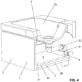
- the drawer 1 is particularly suitable for use in sanitary furniture 2, which is in the Figures 4 and 5 is shown rudimentarily.
- a piece of sanitary furniture 2 is preferably a piece of furniture arranged under a vanity.
- the sanitary furniture 2 can also be referred to as a base cabinet.
- the drawer 1 can also be used in other furniture.
- the drawer 1 comprises a bottom wall 3, two side walls 4, a front wall 5 and a rear wall 6.
- the front wall 5 is in the Figures 1 to 3 not shown.
- the bottom wall 3, the side walls 4, the front wall 5 and the rear wall 6 define a drawer space 7.
- the drawer space 7 is the interior of the drawer 1 in which the users of the drawer 1 can store things.
- the drawer 1 further comprises two pull-out fittings 8 arranged parallel to one another.
- the pull-out fittings 8 are arranged parallel to the side walls 4 and can be pulled out along a pull-out direction A.
- the extension direction A defines a longitudinal axis L.
- the bottom wall 3 has a bulge 9 extending laterally to the side walls 4 in the direction of the longitudinal axis L between the front wall 5 and the rear wall 6.
- a bulge 9 is arranged on each of the side walls 4.
- the bulge 9 provides a receiving space for receiving parts of the pull-out fittings 8.
- the bottom wall 3 can protrude further down between the two bulges 9 or the two pull-out fittings 8, whereby the volume of the drawer space 7 can be maximized.
- the bottom wall 3 is formed with a stepped area 10 between the two bulges 9.
- the drawer space 7 extends downward between the two bulges 9 as seen from the drawer space 7.
- the drawer space 7 extends downwards in such a way that the drawer space 7 extends on the inside between the two bulges, so that the drawer space 7 is enlarged downwards. That is, due to the arrangement of the bulges 9, which accommodate parts of the pull-out fittings 8, the outer surface 12 of the bottom wall 3 is arranged higher in the area of the bulges 9 than in the area of the offset area 10. Due to the arrangement of the remote area 10, the space between the pull-out fittings 8 can be made usable as a drawer space 7.
- the inner surface 11 of the bottom wall 3 facing the drawer space 7 is essentially at the same height as the outer surface 12 of the bottom wall 3 in the area of the bulge 9. This enables a compact drawer structure to be achieved while maximizing the volume of the drawer.
- the inner surface 11 of the bottom wall 3 facing the drawer space 7 is lower than the outer surface 12 of the bottom wall 3 in the region of the bulge 9. This allows a further optimization of the volume to be achieved.
- the side wall 4 extends with respect to the outer wall 12 of the bottom wall 3 in each case in the region of the bulge 9 laterally to the bulge 9.
- the bulge 9 is thereby laterally limited.
- the pull-out fitting 8 protrudes below the side wall and is accordingly accessible from the outside for attachment to a piece of furniture.
- the bulges 9 extend, as already mentioned, completely from the front wall 5 to the rear wall 6. Furthermore, the bulges 9 are arranged symmetrically with respect to a plane of symmetry S running centrally through the drawer 1, parallel to the longitudinal axes L and at right angles to the inner surface 11 of the bottom wall 3 . In this way, a drawer that is balanced in terms of weight can be provided.
- each of the bulges has a width B which corresponds to a maximum of 45% of the total width from side wall to side wall of the drawer 1.
- This design has the advantage that the surface of the inner surface 11 in the area of the offset area 10 is maximized as much as possible, while the surface of the inner surface 11 in the area of the bulge 9 also has a comparatively large area, so that the area of the adjustment areas is sufficient in all areas are large.
- the thickness of the bottom wall 3 is essentially constant over the entire inner surface 11. This has the advantage that the available space is not excessively restricted.
- the stepped area 10 is seen from above onto the inner surface 11 of the interior space 7 In terms of area, it is several times larger than the area in which the bulges 9 are arranged. This has the advantage that the surface area of the inner surface 11 in the area of the offset area 10 can be designed to be as large as possible.
- the outer surface 12 of the bottom wall 3 opposite the recessed area 10 spans a plane E.
- the pull-out fittings 8 penetrate the plane E downwards, as in the Figures 1 to 3 is shown.
- the area of the pull-out fittings 8 protruding downward from the plane E corresponds to a maximum of 20% or a maximum of 45% of the distance D between the plane E and the outer surface 12 of the bulges 9. The smaller the distance D, the more advantageous this is for the maximum space utilization.
- the pull-out fittings 8 each have a first fitting part 14 and a second fitting part 15.
- the fitting parts 14, 15 are connected to one another via a longitudinal guide 16.
- the first fitting part 14 is firmly connected to the drawer in the figures shown with the bottom wall 3 or with the side wall 4.
- the second fitting part can be firmly connected to a piece of furniture 2.
- the second fitting part has corresponding openings 24 through which screws can be passed, with which the second fitting part 15 can be screwed to the piece of furniture 2.
- the drawer 1 also has at least one partition 17 which divides the drawer space 7.
- a partition 17 is arranged in each of the two areas of the transition from the offset area 10 to the bulges 9.
- the partition 17 ensures that things cannot fall from the inner surface 11 above the area of the bulges 9 into the area of the inner surface 11 in the offset area 10.
- the partition 17 preferably runs parallel to the two side walls 4.
- the partition 17 provides the lateral delimitation of the offset area 10 to the area of the two bulges 9.
- the bottom wall 3 is each formed in several parts.
- the bottom wall 3 has a profile element 18.
- the profile element 18 has two opposing grooves 19, and a flat bottom part 20 providing the bottom wall 3 can be correspondingly supported in the said groove 19.
- the profile element 18 represents in the two embodiments according to Figures 1 and 2 also the partition 17 ready.
- bottom wall 3 has a plurality of bottom parts 20 that are glued or screwed to one another.
- the partition wall 17 is also connected to the bottom wall 3 via a screw or adhesive connection.
- the rear wall 6 has a recess 21 which is arranged in such a way that space is created for a siphon pipe part 22 to pass through.
- a piece of furniture 2 in particular a piece of sanitary furniture, comprising a drawer 1 according to the above description is shown.
- the furniture 2 comprises a washstand 25 which can be connected to a water pipe with a siphon pipe part 22.
- the piece of furniture has at least two side parts 23 to which the pull-out fittings 8 can be fastened in such a way that the drawer 1 can be moved relative to the piece of furniture.
Landscapes
- Drawers Of Furniture (AREA)
Abstract
Description
- Die vorliegende Erfindung betrifft eine Schublade, insbesondere eine Schublade für ein Sanitärmöbel, nach dem Oberbegriff von Anspruch 1.
- Aus dem Stand der Technik sind Sanitärmöbel bekannt, welche unter einen Waschtisch anzuordnen sind. Typischerweise umfassen derartige Sanitärmöbel jeweils mindestens eine Schublade. Problematisch dabei ist, dass der Siphon des Waschtisches in den gleichen Raum einragt, in welchen die Schublade sich bewegt. Im Bereich des Siphons lassen sich keine Gegenstände anordnen.
- Auf der anderen Seite, nämlich nach unten hin, wird der Raum durch die Auszugsbeschläge limitiert. Dieses Problem ist bei allen Möbeln anzutreffen.
- Ausgehend von diesem Stand der Technik ist es eine bevorzugte Aufgabe der vorliegenden Erfindung, eine Schublade anzugeben, mit welcher, insbesondere in einem Sanitärmöbel, der zur Verfügung stehende Raum bezüglich des Schubladeninhalts möglichst optimal auszunützen.
- Diese Aufgabe löst der Gegenstand nach Anspruch 1. Demgemäss umfasst eine Schublade, insbesondere für ein Sanitärmöbel, eine Bodenwand, zwei Seitenwände, eine Frontwand und eine Rückwand, wobei die Bodenwand, die Seitenwände, die Frontwand und die Rückwand einen Schubladenraum definieren, und zwei parallel zueinander angeordnete Auszugsbeschläge. Die Auszugsbeschläge sind parallel zu den Seitenwänden angeordnet und sie sind entlang einer Auszugsrichtung herausziehbar. Die Auszugsrichtung definiert eine Längsachse. Die Bodenwand weist seitlich zu den Seitenwänden je eine in Richtung der Längsachse zwischen Frontwand und Rückwand sich erstreckende Ausbuchtung auf, welche Ausbuchtung einen Aufnahmeraum zur Aufnahme von Teilen der Auszugsbeschläge bereitstellt.
- Durch die Anordnung der Ausbuchtung ragen die Auszugsbeschläge nicht von der äusseren Oberfläche der Bodenwand ab, sondern sind versetzt dazu angeordnet. Hierdurch kann die Bauhöhe der Schublade als solche vergrössert werden. Mit anderen Worten erstrecken sich die unteren Bereiche der Schublade in den Bereich zwischen den beiden Auszugsbeschlägen. Mit nochmals anderen Worten gesagt, resultiert ein Raumgewinn nach unten hin.
- Die Bodenwand weist demnach innenseitig und aussenseitig jeweils zwei verschiedene Ebenen auf.
- Die Ausbuchtung erstreckt sich von der Aussenseite der Bodenwand in die Bodenwand hinein, so dass die Auszugsbeschläge mindestens teilweise, insbesondere zu einem grossen Teil, in der Ausbuchtung liegen. Hierdurch kann die Bauhöhe der Schublade und somit die Höhe des Schubladenraums vergrössert werden.
- Die Ausbuchtung erstreckt sich von der Frontwand bis hin zu der Rückwand, derart, dass ein durchgehender Aufnahmeraum zwischen Frontwand und Rückwand entsteht.
- Vorzugsweise ist die Bodenwand zwischen den beiden Ausbuchtungen mit einem abgesetzten Bereich ausgebildet, wobei sich der Schubladenraum zwischen den beiden Ausbuchtungen vom Schubladenraum her gesehen nach unten erstreckt, derart, dass sich der Schubladenraum innenseitig zwischen die beiden Ausbuchtungen erstreckt und dass der Schubladenraum nach unten hin vergrössert wird.
- Die Ausdrucksweise "abgesetzter Bereich" ist vom Schubladenraum her gesehen so zu verstehen, dass die Innenfläche der Bodenwand einen abgesetzten Bereich aufweist, welcher bezüglich den Bereichen, die oberhalb der Ausbuchtungen liegen, nach unten hin abgesetzt ist.
- Die Begriffe, welche eine Richtung, wie "nach unten" angeben, sind jeweils in Einbaulage zu verstehen. Die Richtung "nach unten" ist demnach eine Richtung in Richtung der Schwerkraft nach unten.
- In einer ersten Variante liegt die dem Schubladenraum zugewandte Innenfläche der Bodenwand auf gleicher Höhe wie die Aussenfläche der Bodenwand im Bereich der Ausbuchtung. In einer zweiten Variante liegt die dem Schubladenraum zugewandte Innenfläche der Bodenwand tiefer wie die Aussenfläche der Bodenwand im Bereich der Ausbuchtung. Bei der zweiten Variante ist das Schubladenvolumen grösser als bei der ersten Variante.
- Die Innenfläche der Bodenwand ist die Fläche, welche dem Schubladenraum zugewandt ist. Die Aussenfläche der Bodenwand ist die Fläche, welche gegenüber des Innenraums liegt.
- Vorzugsweise erstreckt sich die Seitenwand bezüglich der Aussenfläche der Bodenwand im Bereich der Ausbuchtung seitlich zur Ausbuchtung und begrenzt die Ausbuchtung seitlich. Die Seitenwand kann demnach die Ausbuchtung seitlich begrenzen. Nebst der Begrenzung der Ausbuchtung wird durch die in den Bereich der Ausbuchtung verlängerte Seitenwand die Stabilität der Schublade als Ganzes erhöht.
- Vorzugsweise sind die Ausbuchtungen bezüglich einer mittig durch die Schublade, parallel zu den Längsachsen und rechtwinklig zur Innenfläche der Bodenwand verlaufenden Symmetrieebene symmetrisch zueinander angeordnet.
- Vorzugsweise weist jede der Ausbuchtungen eine Breite auf, welche maximal 45% der Gesamtbreite von Seitenwand zu Seitenwand der Schublade entspricht. Je nach Anwendungsfall sind auch kleinere Breiten denkbar. Die Breite hängt im Wesentlichen von ergonomischen Gesichtspunkten ab.
- Dieser Bereich ist besonders vorteilhaft, weil der Innenraum dadurch maximiert werden kann und zudem im Bereich der Ausbuchtungen Stellflächen bereitgestellt werden. Eine sehr kleine Breite wäre auch denkbar, was dann aber bei einem Schubladenboden mit konstanter Dicke der Bodenwand zu Lasten der Stellfläche gehen würde.
- Vorzugsweise ist die Dicke der Bodenwand über die gesamte Innenfläche im Wesentlichen konstant. Im Wesentlichen konstant heisst in diesem Fall, dass die Dicke der Bodenwand allen Bereichen konstant ist, abgesehen von kleinen Bereichen beim Übergang von der Ausbuchtung zu den anderen Teilen der Schublade.
- Vorzugsweise ist, von oben auf die Innenfläche des Schubladenraums gesehen, der abgesetzte Bereich flächenmässig um ein Mehrfaches grösser als der Bereich, in welchem die Ausbuchtung angeordnet ist. Der abgesetzte Bereich kann flächenmässig aber auch kleiner sein als der Bereich, in welchem die Ausbuchtung angeordnet ist.
- Vorzugsweise spannt die Aussenfläche der Bodenwand gegenüber des abgesetzten Bereiches eine Ebene auf, wobei die Auszugsbeschläge die Ebene nach unten hin durchdringen, derart, dass der von der Ebene abragende Bereich der Auszugsbeschläge höchstens 20% oder höchstens 45% der Distanz zwischen der Ebene und der Aussenfläche der Ausbuchtung entspricht.
- Vorzugsweise weisen die Auszugsbeschläge jeweils ein erstes Beschlagsteil und ein zweites Beschlagsteil auf, welche Beschlagsteile über eine Längsführung miteinander in Verbindung stehen, wobei das erste Beschlagsteil fest mit der Schublade, insbesondere mit der Bodenwand oder der Seitenwand, verbunden ist, und wobei das zweite Beschlagsteil fest mit einem Möbel verbindbar ist.
- Vorzugsweise weist die Schublade weiter mindestens eine den Schubladenraum teilende Trennwand auf, die sich parallel zu den beiden Seitenwänden quer durch den Schubladenraum erstreckt.
- Vorzugsweise stellt die Trennwand die seitliche Begrenzung des abgesetzten Bereichs bereit.
- Die Trennwand kann weiterhin mit optionalen Leuchtelementen, wie LED-Streifen, versehen sein.
- In einer Variante ist die Bodenwand einstückig ausgebildet. Beispielsweise kann die Bodenwand aus Kunststoff hergestellt sein.
- In einer anderen Variante ist die Bodenwand mehrteilig ausgebildet, wobei die Bodenwand ein Profilelement aufweist, welches zwei gegenübereinander liegende Nuten umfasst, wobei jeweils ein die Bodenwand bereitstellendes flächiges Bodenteil in der besagten Nute lagerbar ist; oder wobei die Bodenwand mehrere miteinander verklebte oder verschraubte Bodenteile aufweist.
- Das Profilelement kann in einer besonders bevorzugten Ausführungsform in den Schubladenraum einragen und die besagte Trennwand bereitstellen.
- Vorzugsweise weist die Rückwand eine Ausnehmung auf, derart, dass Raum für die Durchführung eines Siphonrohrteils geschaffen wird.
- Ein Möbel, insbesondere ein Sanitärmöbel, umfasst mindestens eine Schublade nach obiger Beschreibung, wobei das Möbel mindestens zwei Seitenteile aufweist, an welchen die Auszugsbeschläge befestigt sind, derart, dass die Schublade relativ zum Möbel verschiebbar ist.
- Weitere Ausführungsformen sind in den abhängigen Ansprüchen angegeben.
- Bevorzugte Ausführungsformen der Erfindung werden im Folgenden anhand der Zeichnungen beschrieben, die lediglich zur Erläuterung dienen und nicht einschränkend auszulegen sind. In den Zeichnungen zeigen:
- Fig. 1
- eine perspektivische Ansicht einer erfindungsgemässen Schublade nach einer ersten Ausführungsform von vorne;
- Fig. 2
- eine perspektivische Ansicht einer erfindungsgemässen Schublade nach einer zweiten Ausführungsform von vorne;
- Fig. 3
- eine perspektivische Ansicht einer erfindungsgemässen Schublade nach einer dritten Ausführungsform von vorne;
- Fig. 4
- eine perspektivische Schnittansicht eines Sanitärmöbels, hier eines Waschtischmöbels, mit einer der Schubladen nach den vorhergehenden Figuren, und
- Fig. 5
- eine Schnittansicht des Waschtischmöbels nach
Figur 4 . - In den
Figuren 1 bis 3 werden perspektivische Ansichten einer Schublade 1 gemäss drei verschiedenen Ausführungsformen gezeigt. In der Folge wird zuerst die allgemeine Struktur der Schublade 1 erläutert und nachfolgend werden die Details der verschiedenen Ausführungsformen erläutert. - Die Schublade 1 ist insbesondere für den Einsatz für ein Sanitärmöbel 2, welches in den
Figuren 4 und5 ansatzweise gezeigt wird, ausgebildet. Ein Sanitärmöbel 2 ist vorzugsweise ein unter einem Waschtisch angeordnetes Möbel. Das Sanitärmöbel 2 kann auch als Unterschrank bezeichnet werden. Die Schublade 1 kann aber auch in anderen Möbeln eingesetzt werden. - Die Schublade 1 umfasst eine Bodenwand 3, zwei Seitenwände 4, eine Frontwand 5 und eine Rückwand 6. Die Frontwand 5 ist in den
Figuren 1 bis 3 nicht dargestellt. Die Bodenwand 3, die Seitenwände 4, die Frontwand 5 und die Rückwand 6 definieren einen Schubladenraum 7. Der Schubladenraum 7 ist dabei der Innenraum der Schublade 1, in welchem die Benützer der Schublade 1 Dinge aufbewahren können. - Weiter umfasst die Schublade 1 zwei parallel zueinander angeordnete Auszugsbeschläge 8. Die Auszugsbeschläge 8 sind dabei parallel zu den Seitenwänden 4 angeordnet und lassen sich entlang einer Auszugsrichtung A herausziehen. Die Auszugsrichtung A definiert eine Längsachse L.
- Die Bodenwand 3 weist seitlich zu den Seitenwänden 4 je eine in Richtung der Längsachse L zwischen Frontwand 5 und Rückwand 6 sich erstreckende Ausbuchtung 9 auf. Bei jeder der Seitenwände 4 ist eine Ausbuchtung 9 angeordnet. Die Ausbuchtung 9 stellt dabei einen Aufnahmeraum zur Aufnahme von Teilen der Auszugsbeschläge 8 bereit. Hierdurch kann die Bodenwand 3 zwischen den beiden Ausbuchtungen 9 bzw. den beiden Auszugsbeschlägen 8 weiter nach unten ragen, wodurch das Volumen des Schubladenraums 7 maximiert werden kann.
- Die Bodenwand 3 ist zwischen den beiden Ausbuchtungen 9 mit einem abgesetzten Bereich 10 ausgebildet. Der Schubladenraum 7 erstreckt sich zwischen den beiden Ausbuchtungen 9 vom Schubladenraum 7 her gesehen nach unten. Dabei erstreckt sich der Schubladenraum 7 derart nach unten, dass sich der Schubladenraum 7 innenseitig zwischen die beiden Ausbuchtungen erstreckt, derart dass der Schubladenraum 7 nach unten hin vergrössert wird. Das heisst, durch die Anordnung der Ausbuchtungen 9, welche Teile der Auszugsbeschläge 8 aufnehmen, ist Aussenfläche 12 der Bodenwand 3 im Bereich der Ausbuchtungen 9 höher angeordnet als im Bereich des abgesetzten Bereichs 10. Durch die Anordnung des abgesetzten Bereichs 10 kann der Raumbereich zwischen den Auszugsbeschlägen 8 entsprechend als Schubladenraum 7 nutzbar gemacht werden.
- In den Ausführungsformen gemäss der
Figuren 1 und3 liegt die dem Schubladenraum 7 zugewandte Innenfläche 11 der Bodenwand 3 im Wesentlichen auf gleicher Höhe wie die Aussenfläche 12 der Bodenwand 3 im Bereich der Ausbuchtung 9. Hierdurch kann eine kompakte Schubladenstruktur unter Maximierung des Volumens der Schublade erreicht werden. In der Ausführungsform gemäss derFigur 2 liegt die dem Schubladenraum 7 zugewandte Innenfläche 11 der Bodenwand 3 tiefer als die Aussenfläche 12 der Bodenwand 3 im Bereich der Ausbuchtung 9. Hierdurch kann eine weitergehende Optimierung des Volumens erreicht werden. - Die Seitenwand 4 erstreckt sich bezüglich der Aussenwand 12 der Bodenwand 3 jeweils in den Bereich der Ausbuchtung 9 seitlich zur Ausbuchtung 9. Hierdurch wird die Ausbuchtung 9 seitlich begrenzt. Der Auszugsbeschlag 8 ragt jeweils unterhalb der Seitenwand hindurch und ist von aussen her entsprechend für die Befestigung an einem Möbel zugänglich.
- Die Ausbuchtungen 9 erstrecken sich, wie bereits erwähnt, vollständig von der Frontwand 5 zur Rückwand 6. Weiter sind die Ausbuchtungen 9 bezüglich einer mittig durch die Schublade 1, parallel zu den Längsachsen L und rechtwinklig zur Innenfläche 11 der Bodenwand 3 verlaufenden Symmetrieebene S symmetrisch angeordnet. Hierdurch kann eine gewichtsmässig austarierte Schublade bereitgestellt werden.
- Weiter weist jede der Ausbuchtungen eine Breite B auf, welche maximal 45% der Gesamtbreite von Seitenwand zu Seitenwand der Schublade 1 entspricht. Durch diese Ausbildung ergeht der Vorteil, dass die Oberfläche der Innenfläche 11 im Bereich des abgesetzten Bereichs 10 möglichst maximiert wird, während die Oberfläche der Innenfläche 11 im Bereich der Ausbuchtung 9 aber ebenfalls eine vergleichsweise grosse Fläche aufweist, sodass die Stellbereiche in allen Flächenbereichen flächenmässig genügend gross ausgebildet sind.
- Die Dicke der Bodenwand 3 ist über die gesamte Innenfläche 11 gesehen im Wesentlichen konstant. Dies hat den Vorteil, dass der zur Verfügung stehende Raum nicht übermässig eingeschränkt wird.
- Von oben auf die Innenfläche 11 des Innenraums 7 gesehen ist der abgesetzte Bereich 10 flächenmässig um ein Mehrfaches grösser als der Bereich, in welchem die Ausbuchtungen 9 angeordnet sind. Hierdurch ergeht der Vorteil, dass der Flächenbereich der Innenfläche 11 im Bereich des abgesetzten Bereichs 10 möglichst grossflächig ausgebildet werden kann.
- Die Aussenfläche 12 der Bodenwand 3 gegenüber des abgesetzten Bereichs 10 spannt eine Ebene E auf. Die Auszugsbeschläge 8 durchdringen dabei die Ebene E nach unten hin, so wie dies in den
Figuren 1 bis 3 gezeigt ist. Der von der Ebene E nach unten hin abragende Bereich der Auszugsbeschläge 8 entspricht aber höchstens 20% oder höchstens 45% der Distanz D zwischen der Ebene E und der Aussenfläche 12 der Ausbuchtungen 9. Je kleiner die Distanz D ausgebildet ist, desto vorteilhafter ist dies für die maximale Raumausnützung. - Die Auszugsbeschläge 8 weisen jeweils ein erstes Beschlagsteil 14 und ein zweites Beschlagsteil 15 auf. Die Beschlagsteile 14, 15 stehen über eine Längsführung 16 miteinander in Verbindung. Das erste Beschlagsteil 14 ist dabei fest mit der Schublade in den gezeigten Figuren mit der Bodenwand 3 oder mit der Seitenwand 4 verbunden. Das zweite Beschlagsteil ist fest mit einem Möbel 2 verbindbar. Das zweite Beschlagsteil weist entsprechende Öffnungen 24 auf, durch die Schrauben geführt werden können, mit welchen das zweite Beschlagsteil 15 zum Möbel 2 verschraubt werden kann.
- Die Schublade 1 weist weiter mindestens eine Trennwand 17 auf, die den Schubladenraum 7 teilt. In der gezeigten Ausführungsform sind in den zwei Bereichen des Übergangs vom abgesetzten Bereich 10 zu den Ausbuchtungen 9 jeweils eine Trennwand 17 angeordnet. Mit der Trennwand 17 wird sichergestellt, dass Dinge nicht von der Innenfläche 11 über dem Bereich der Ausbuchtungen 9 in den Bereich der Innenfläche 11 im abgesetzten Bereich 10 fallen können. Die Trennwand 17 verläuft vorzugsweise parallel zu den beiden Seitenwänden 4.
- Die Trennwand 17 stellt, wie bereits erwähnt, die seitliche Begrenzung des abgesetzten Bereichs 10 zum Bereich der beiden Ausbuchtungen 9 bereit.
- In den
Figuren 1 und 2 ist die Bodenwand 3 jeweils mehrteilig ausgebildet. Die Bodenwand 3 weist dabei ein Profilelement 18 auf. Das Profilelement 18 weist jeweils zwei gegenüberliegende Nuten 19 auf, jeweils ein die Bodenwand 3 bereitstellendes flächiges Bodenteil 20 ist in der besagten Nute 19 entsprechend lagerbar. Das Profilelement 18 stellt in den beiden Ausführungsformen gemäss derFiguren 1 und 2 zudem die Trennwand 17 bereit. - In der
Figur 3 wird eine weitere Ausführungsform gezeigt. Hier weist die Bodenwand 3 mehrere miteinander verklebte oder verschraubte Bodenteile 20 auf. Die Trennwand 17 wird ebenfalls mit der Bodenwand 3 über eine Schraub- oder Klebeverbindung verbunden. - Von den
Figuren 1 bis 3 wird weiter gezeigt, dass die Rückwand 6 eine Ausnehmung 21 aufweist, welche derart angeordnet ist, dass Raum für die Durchführung eines Siphonrohrteils 22 schaffen wird. - In der
Figur 4 wird ein Möbel 2, insbesondere ein Sanitärmöbel, umfassend einer Schublade 1 nach der obigen Beschreibung gezeigt. In der gezeigten Ausführungsform umfasst das Möbel 2 einen Waschtisch 25, der mit einem Siphonrohrteil 22 an einer Wasserleitung angeschlossen werden kann. Das Möbel weist dabei mindestens zwei Seitenteile 23 auf, an welchen die Auszugsbeschläge 8 befestigbar sind, derart, dass die Schublade 1 relativ zum Möbel verschiebbar ist. - In der
Figur 5 wird eine Seitenansicht gezeigt. Von derFigur 5 werden die Vorteile der vorliegenden Erfindung klar. Durch die Anordnung der Ausbuchtungen 9, in welchen die Auszugsbeschläge 8 mindestens teilweise aufgenommen sind, kann die Bodenwand im abgesetzten Bereich 10 weiter nach unten geführt werden, nämlich in Richtung des Bodens 26 des Sanitärmöbels 2. Hierdurch kann der zur Verfügung stehende Innenraum optimal ausgenützt werden. Weiter wird der Raum insbesondere im Bereich des Siphonrohrteils 22 optimiert.BEZUGSZEICHENLISTE 1 Schublade 22 Siphonrohrteil 2 Möbel, insbesondere Sanitärmöbel 23 24 Seitenteile Öffnungen 3 Bodenwand 25 Waschtisch 4 Seitenwand 26 Boden 5 Frontwand A Auszugsrichtung 6 Rückwand B Breite 7 Schubladenraum D Distanz 8 Auszugsbeschlag E Ebene 9 Ausbuchtung L Längsachse 10 abgesetzter Bereich S Symmetrieebene 11 Innenfläche 12 Aussenfläche 14 erstes Beschlagsteil 15 zweites Beschlagsteil 16 Längsführung 17 Trennwand 18 Profilelement 19 Nuten 20 Bodenteil 21 Ausnehmung
Claims (15)
- Schublade (1), insbesondere für ein Sanitärmöbel (2), umfassend
eine Bodenwand (3), zwei Seitenwände (4), eine Frontwand (5) und eine Rückwand (6), wobei die Bodenwand (3), die Seitenwände (4), die Frontwand (5) und die Rückwand (6) einen Schubladenraum (7) definieren,
und
zwei parallel zueinander angeordnete Auszugsbeschläge (8), welche parallel zu den Seitenwänden (4) angeordnet sind und entlang einer Auszugsrichtung (A) herausziehbar sind, wobei die Auszugsrichtung (A) eine Längsachse (L) definiert,
dadurch gekennzeichnet,
dass die Bodenwand (3) seitlich zu den Seitenwänden (4) je eine in Richtung der Längsachse (L) zwischen Frontwand (5) und Rückwand (6) sich erstreckende Ausbuchtung (9) aufweist, welche Ausbuchtung (9) einen Aufnahmeraum zur Aufnahme von Teilen der Auszugsbeschläge (8) bereitstellt. - Schublade (1) nach Anspruch 1, dadurch gekennzeichnet, dass die Bodenwand (3) zwischen den beiden Ausbuchtungen (9) mit einem abgesetzten Bereich (10) ausgebildet ist, wobei sich der Schubladenraum (7) zwischen den beiden Ausbuchtungen (9) vom Schubladenraum (7) her gesehen nach unten erstreckt, derart, dass sich der Schubladenraum (7) innenseitig zwischen die beiden Ausbuchtungen (9) erstreckt und dass der Schubladenraum (7) nach unten hin vergrössert wird.
- Schublade (1) nach Anspruch 1 oder 2, dadurch gekennzeichnet, dass die dem Schubladenraum (7) zugewandte Innenfläche (11) der Bodenwand (3), insbesondere im abgesetzten Bereich (10), auf gleicher Höhe liegt wie die Aussenfläche (12) der Bodenwand (3) im Bereich der Ausbuchtung (9); oder dass die dem Schubladenraum (7) zugewandte Innenfläche (11) der Bodenwand (3), insbesondere im abgesetzten Bereich (10), tiefer liegt wie die Aussenfläche (12) der Bodenwand (3) im Bereich der Ausbuchtung (9).
- Schublade (1) nach einem der vorhergehenden Ansprüche, dadurch gekennzeichnet, dass sich die Seitenwand (4) bezüglich der Aussenfläche (12) der Bodenwand (3) im Bereich der Ausbuchtung (9) seitlich zur Ausbuchtung (9) erstreckt und die Ausbuchtung (9) seitlich begrenzt.
- Schublade (1) nach einem der vorhergehenden Ansprüche, dadurch gekennzeichnet, dass die Ausbuchtungen (9) bezüglich einer mittig durch die Schublade (1), parallel zu den Längsachsen (L) und rechtwinklig zur Innenfläche (11) der Bodenwand (3) verlaufenden Symmetrieebene (S) symmetrisch zueinander angeordnet sind.
- Schublade (1) nach einem der vorhergehenden Ansprüche, dadurch gekennzeichnet, dass jede der Ausbuchtungen (9) eine Breite (B) aufweist, welche maximal 45% der Gesamtbreite von Seitenwand (4) zu Seitenwand (4) der Schublade (1) entspricht.
- Schublade (1) nach einem der vorhergehenden Ansprüche, dadurch gekennzeichnet, dass die Dicke der Bodenwand (3) über die gesamte Innenfläche (11) im Wesentlichen konstant ist.
- Schublade (1) nach einem der vorhergehenden Ansprüche, dadurch gekennzeichnet, dass von oben auf die Innenfläche (11) des Schubladenraums (7) gesehen, der abgesetzte Bereich (10) flächenmässig um ein Mehrfaches grösser oder kleiner ist als der Bereich, in welchem die Ausbuchtung (9) angeordnet ist.
- Schublade (1) nach einem der vorhergehenden Ansprüche, dadurch gekennzeichnet, dass die Aussenfläche (12) der Bodenwand (3) gegenüber des abgesetzten Bereichs (10) eine Ebene (E) aufspannt, wobei die Auszugsbeschläge (8) die Ebene (E) nach unten hin durchdringen, derart, dass der von der Ebene (E) abragende Bereich der Auszugsbeschläge (8) höchstens 20% oder höchstens 45% der Distanz (D) zwischen der Ebene (E) und der Aussenfläche (12) der Ausbuchtung (9) entspricht.
- Schublade (1) nach einem der vorhergehenden Ansprüche, dadurch gekennzeichnet, dass die Auszugsbeschläge (8) jeweils ein erstes Beschlagsteil (14) und ein zweites Beschlagsteil (15) aufweisen, welche Beschlagsteile (14, 15) über eine Längsführung (16) miteinander in Verbindung stehen, wobei das erste Beschlagsteil (14) fest mit der Schublade (1), insbesondere mit der Bodenwand (3) oder der Seitenwand (4), verbunden ist, und wobei das zweite Beschlagsteil (15) fest mit einem Möbel (2) verbindbar ist.
- Schublade (1) nach einem der vorhergehenden Ansprüche, dadurch gekennzeichnet, dass die Schublade (1) weiter mindestens eine Trennwand (17) aufweist, die den Schubladenraum (7) teilt, sich parallel zu den beiden Seitenwänden (4) quer durch den Schubladenraum (7) erstreckt.
- Schublade (1) nach Anspruch 2 und einem der Ansprüche 3 bis 11, dadurch gekennzeichnet, dass die Trennwand (17) die seitliche Begrenzung des abgesetzten Bereichs (10) bereitstellt.
- Schublade (1) nach einem der vorhergehenden Ansprüche, dadurch gekennzeichnet,
dass die Bodenwand (3) einstückig ausgebildet ist;
oder
dass die Bodenwand (3) mehrteilig ausgebildet, wobei die Bodenwand (3) ein Profilelement (18) aufweist, welches zwei gegenübereinander liegende Nuten (19) umfasst, wobei jeweils ein die Bodenwand (3) bereitstellendes flächiges Bodenteil (20) in der besagten Nute (19) lagerbar ist; oder wobei die Bodenwand (3) mehrere miteinander verklebte oder verschraubte Bodenteile (20) aufweist. - Schublade (1) nach einem der vorhergehenden Ansprüche, dadurch gekennzeichnet, dass die Rückwand (6) eine Ausnehmung (21) aufweist, derart, dass Raum für die Durchführung eines Siphonrohrteils (22) geschaffen wird.
- Möbel, insbesondere Sanitärmöbel, umfassend mindestens eine Schublade nach einem der vorhergehenden Ansprüche, wobei das Möbel mindestens zwei Seitenteile (23) aufweist, an welchen die Auszugsbeschläge (8) befestigt sind, derart, dass die Schublade (1) relativ zum Möbel verschiebbar ist.
Priority Applications (1)
| Application Number | Priority Date | Filing Date | Title |
|---|---|---|---|
| EP19215588.5A EP3834665B1 (de) | 2019-12-12 | 2019-12-12 | Schublade, insbesondere für sanitärmöbel |
Applications Claiming Priority (1)
| Application Number | Priority Date | Filing Date | Title |
|---|---|---|---|
| EP19215588.5A EP3834665B1 (de) | 2019-12-12 | 2019-12-12 | Schublade, insbesondere für sanitärmöbel |
Publications (2)
| Publication Number | Publication Date |
|---|---|
| EP3834665A1 true EP3834665A1 (de) | 2021-06-16 |
| EP3834665B1 EP3834665B1 (de) | 2023-03-01 |
Family
ID=68887297
Family Applications (1)
| Application Number | Title | Priority Date | Filing Date |
|---|---|---|---|
| EP19215588.5A Active EP3834665B1 (de) | 2019-12-12 | 2019-12-12 | Schublade, insbesondere für sanitärmöbel |
Country Status (1)
| Country | Link |
|---|---|
| EP (1) | EP3834665B1 (de) |
Citations (3)
| Publication number | Priority date | Publication date | Assignee | Title |
|---|---|---|---|---|
| US20050046317A1 (en) * | 2003-08-26 | 2005-03-03 | Howard Glenn A. | Drawer system |
| DE202008009396U1 (de) * | 2008-07-14 | 2009-11-26 | Paul Hettich Gmbh & Co. Kg | Schubkasten |
| WO2011094772A1 (de) * | 2010-02-03 | 2011-08-11 | Julius Blum Gmbh | Schubladensystem |
Family Cites Families (3)
| Publication number | Priority date | Publication date | Assignee | Title |
|---|---|---|---|---|
| FR2621794A1 (fr) * | 1987-10-19 | 1989-04-21 | Lugez Denise | Bloc-tiroirs de rangement, a encoche, encastrable sous une paillasse pourvue d'un evier ou d'un lavabo |
| SI22602A (sl) * | 2007-10-30 | 2009-04-30 | Gorenje Gospodinjski Aparati, D.D. | Sklop predala in kolesnih izvlečnih vodil zanj |
| DE102017108453A1 (de) * | 2017-04-20 | 2018-10-25 | Paul Hettich Gmbh & Co. Kg | Möbel |
-
2019
- 2019-12-12 EP EP19215588.5A patent/EP3834665B1/de active Active
Patent Citations (3)
| Publication number | Priority date | Publication date | Assignee | Title |
|---|---|---|---|---|
| US20050046317A1 (en) * | 2003-08-26 | 2005-03-03 | Howard Glenn A. | Drawer system |
| DE202008009396U1 (de) * | 2008-07-14 | 2009-11-26 | Paul Hettich Gmbh & Co. Kg | Schubkasten |
| WO2011094772A1 (de) * | 2010-02-03 | 2011-08-11 | Julius Blum Gmbh | Schubladensystem |
Also Published As
| Publication number | Publication date |
|---|---|
| EP3834665B1 (de) | 2023-03-01 |
Similar Documents
| Publication | Publication Date | Title |
|---|---|---|
| EP1084661A1 (de) | Unterteilungssystem | |
| AT406999B (de) | Halterungs-anordnung für schubladen-böden an den seitenwänden der schublade | |
| AT3898U1 (de) | Blendenbefestigungsvorrichtung für schubladen | |
| DE202017006852U1 (de) | Verbindungsstück für die feste Verbindung einer ersten und einer zweiten Platte von Möbelstücken und anderen Einrichtungsgegenständen | |
| AT403341B (de) | Halterungsbeschlag für schubladen-ausziehführungen | |
| DE202017006853U1 (de) | Verstecktes Verbindungssystem mit Betätigung von vorne für einen Boden von Möbelstücken und Einrichtungsgegenständen | |
| EP0784951A1 (de) | Vorrichtung mit Funktionsteilen | |
| EP3569102B1 (de) | Befestigungssystem für einen waschtisch | |
| DE102019116044A1 (de) | Regalsystem und Regalseitenwand für ein Regalsystem | |
| EP0386559B1 (de) | Duschabtrennung | |
| AT401851B (de) | Beschlag | |
| EP3834665B1 (de) | Schublade, insbesondere für sanitärmöbel | |
| CH716361B1 (de) | Schublade, insbesondere für Sanitärmöbel. | |
| EP3695748B1 (de) | Einbauschrankanordnung | |
| AT401860B (de) | Schublade | |
| AT520822B1 (de) | Schubladenseitenwand | |
| EP1257185B1 (de) | Verbindungselement für ein möbelstück, insbesondere für einen tisch | |
| DE102010018368A1 (de) | Trennwandsystem für den Innenausbau | |
| DE202014100557U1 (de) | Möbelauszug und Frontblende für einen Möbelauszug | |
| DE2828031C3 (de) | Trennwand für eine Dusch- oder Badewannenabtrennung | |
| EP3708727A1 (de) | Sanitärartikelanordnung | |
| DE1708126A1 (de) | Beschlag fuer Schiebetueren | |
| EP3569121B1 (de) | Waschtischanordnung | |
| CH543259A (de) | Möbel oder Gestell mit einem ausziehbaren Teil | |
| DE3913854C2 (de) |
Legal Events
| Date | Code | Title | Description |
|---|---|---|---|
| PUAI | Public reference made under article 153(3) epc to a published international application that has entered the european phase |
Free format text: ORIGINAL CODE: 0009012 |
|
| STAA | Information on the status of an ep patent application or granted ep patent |
Free format text: STATUS: THE APPLICATION HAS BEEN PUBLISHED |
|
| AK | Designated contracting states |
Kind code of ref document: A1 Designated state(s): AL AT BE BG CH CY CZ DE DK EE ES FI FR GB GR HR HU IE IS IT LI LT LU LV MC MK MT NL NO PL PT RO RS SE SI SK SM TR |
|
| STAA | Information on the status of an ep patent application or granted ep patent |
Free format text: STATUS: REQUEST FOR EXAMINATION WAS MADE |
|
| 17P | Request for examination filed |
Effective date: 20210625 |
|
| RBV | Designated contracting states (corrected) |
Designated state(s): AL AT BE BG CH CY CZ DE DK EE ES FI FR GB GR HR HU IE IS IT LI LT LU LV MC MK MT NL NO PL PT RO RS SE SI SK SM TR |
|
| STAA | Information on the status of an ep patent application or granted ep patent |
Free format text: STATUS: EXAMINATION IS IN PROGRESS |
|
| 17Q | First examination report despatched |
Effective date: 20210825 |
|
| RIC1 | Information provided on ipc code assigned before grant |
Ipc: A47B 88/969 20170101ALN20220209BHEP Ipc: A47B 88/427 20170101AFI20220209BHEP |
|
| RIC1 | Information provided on ipc code assigned before grant |
Ipc: A47B 88/969 20170101ALN20220218BHEP Ipc: A47B 88/427 20170101AFI20220218BHEP |
|
| GRAP | Despatch of communication of intention to grant a patent |
Free format text: ORIGINAL CODE: EPIDOSNIGR1 |
|
| STAA | Information on the status of an ep patent application or granted ep patent |
Free format text: STATUS: GRANT OF PATENT IS INTENDED |
|
| RIC1 | Information provided on ipc code assigned before grant |
Ipc: A47B 88/969 20170101ALN20220829BHEP Ipc: A47B 88/427 20170101AFI20220829BHEP |
|
| INTG | Intention to grant announced |
Effective date: 20220922 |
|
| GRAS | Grant fee paid |
Free format text: ORIGINAL CODE: EPIDOSNIGR3 |
|
| GRAA | (expected) grant |
Free format text: ORIGINAL CODE: 0009210 |
|
| STAA | Information on the status of an ep patent application or granted ep patent |
Free format text: STATUS: THE PATENT HAS BEEN GRANTED |
|
| AK | Designated contracting states |
Kind code of ref document: B1 Designated state(s): AL AT BE BG CH CY CZ DE DK EE ES FI FR GB GR HR HU IE IS IT LI LT LU LV MC MK MT NL NO PL PT RO RS SE SI SK SM TR |
|
| REG | Reference to a national code |
Ref country code: GB Ref legal event code: FG4D Free format text: NOT ENGLISH |
|
| REG | Reference to a national code |
Ref country code: CH Ref legal event code: EP Ref country code: AT Ref legal event code: REF Ref document number: 1550417 Country of ref document: AT Kind code of ref document: T Effective date: 20230315 |
|
| REG | Reference to a national code |
Ref country code: DE Ref legal event code: R096 Ref document number: 502019007081 Country of ref document: DE |
|
| REG | Reference to a national code |
Ref country code: IE Ref legal event code: FG4D Free format text: LANGUAGE OF EP DOCUMENT: GERMAN |
|
| REG | Reference to a national code |
Ref country code: NL Ref legal event code: FP |
|
| REG | Reference to a national code |
Ref country code: LT Ref legal event code: MG9D |
|
| P01 | Opt-out of the competence of the unified patent court (upc) registered |
Effective date: 20230523 |
|
| PG25 | Lapsed in a contracting state [announced via postgrant information from national office to epo] |
Ref country code: RS Free format text: LAPSE BECAUSE OF FAILURE TO SUBMIT A TRANSLATION OF THE DESCRIPTION OR TO PAY THE FEE WITHIN THE PRESCRIBED TIME-LIMIT Effective date: 20230301 Ref country code: NO Free format text: LAPSE BECAUSE OF FAILURE TO SUBMIT A TRANSLATION OF THE DESCRIPTION OR TO PAY THE FEE WITHIN THE PRESCRIBED TIME-LIMIT Effective date: 20230601 Ref country code: LV Free format text: LAPSE BECAUSE OF FAILURE TO SUBMIT A TRANSLATION OF THE DESCRIPTION OR TO PAY THE FEE WITHIN THE PRESCRIBED TIME-LIMIT Effective date: 20230301 Ref country code: LT Free format text: LAPSE BECAUSE OF FAILURE TO SUBMIT A TRANSLATION OF THE DESCRIPTION OR TO PAY THE FEE WITHIN THE PRESCRIBED TIME-LIMIT Effective date: 20230301 Ref country code: HR Free format text: LAPSE BECAUSE OF FAILURE TO SUBMIT A TRANSLATION OF THE DESCRIPTION OR TO PAY THE FEE WITHIN THE PRESCRIBED TIME-LIMIT Effective date: 20230301 Ref country code: ES Free format text: LAPSE BECAUSE OF FAILURE TO SUBMIT A TRANSLATION OF THE DESCRIPTION OR TO PAY THE FEE WITHIN THE PRESCRIBED TIME-LIMIT Effective date: 20230301 |
|
| PG25 | Lapsed in a contracting state [announced via postgrant information from national office to epo] |
Ref country code: SE Free format text: LAPSE BECAUSE OF FAILURE TO SUBMIT A TRANSLATION OF THE DESCRIPTION OR TO PAY THE FEE WITHIN THE PRESCRIBED TIME-LIMIT Effective date: 20230301 Ref country code: PL Free format text: LAPSE BECAUSE OF FAILURE TO SUBMIT A TRANSLATION OF THE DESCRIPTION OR TO PAY THE FEE WITHIN THE PRESCRIBED TIME-LIMIT Effective date: 20230301 Ref country code: GR Free format text: LAPSE BECAUSE OF FAILURE TO SUBMIT A TRANSLATION OF THE DESCRIPTION OR TO PAY THE FEE WITHIN THE PRESCRIBED TIME-LIMIT Effective date: 20230602 Ref country code: FI Free format text: LAPSE BECAUSE OF FAILURE TO SUBMIT A TRANSLATION OF THE DESCRIPTION OR TO PAY THE FEE WITHIN THE PRESCRIBED TIME-LIMIT Effective date: 20230301 |
|
| PG25 | Lapsed in a contracting state [announced via postgrant information from national office to epo] |
Ref country code: SM Free format text: LAPSE BECAUSE OF FAILURE TO SUBMIT A TRANSLATION OF THE DESCRIPTION OR TO PAY THE FEE WITHIN THE PRESCRIBED TIME-LIMIT Effective date: 20230301 Ref country code: RO Free format text: LAPSE BECAUSE OF FAILURE TO SUBMIT A TRANSLATION OF THE DESCRIPTION OR TO PAY THE FEE WITHIN THE PRESCRIBED TIME-LIMIT Effective date: 20230301 Ref country code: PT Free format text: LAPSE BECAUSE OF FAILURE TO SUBMIT A TRANSLATION OF THE DESCRIPTION OR TO PAY THE FEE WITHIN THE PRESCRIBED TIME-LIMIT Effective date: 20230703 Ref country code: EE Free format text: LAPSE BECAUSE OF FAILURE TO SUBMIT A TRANSLATION OF THE DESCRIPTION OR TO PAY THE FEE WITHIN THE PRESCRIBED TIME-LIMIT Effective date: 20230301 Ref country code: CZ Free format text: LAPSE BECAUSE OF FAILURE TO SUBMIT A TRANSLATION OF THE DESCRIPTION OR TO PAY THE FEE WITHIN THE PRESCRIBED TIME-LIMIT Effective date: 20230301 |
|
| PG25 | Lapsed in a contracting state [announced via postgrant information from national office to epo] |
Ref country code: SK Free format text: LAPSE BECAUSE OF FAILURE TO SUBMIT A TRANSLATION OF THE DESCRIPTION OR TO PAY THE FEE WITHIN THE PRESCRIBED TIME-LIMIT Effective date: 20230301 Ref country code: IS Free format text: LAPSE BECAUSE OF FAILURE TO SUBMIT A TRANSLATION OF THE DESCRIPTION OR TO PAY THE FEE WITHIN THE PRESCRIBED TIME-LIMIT Effective date: 20230701 |
|
| REG | Reference to a national code |
Ref country code: DE Ref legal event code: R097 Ref document number: 502019007081 Country of ref document: DE |
|
| PLBE | No opposition filed within time limit |
Free format text: ORIGINAL CODE: 0009261 |
|
| STAA | Information on the status of an ep patent application or granted ep patent |
Free format text: STATUS: NO OPPOSITION FILED WITHIN TIME LIMIT |
|
| PGFP | Annual fee paid to national office [announced via postgrant information from national office to epo] |
Ref country code: GB Payment date: 20231220 Year of fee payment: 5 |
|
| PG25 | Lapsed in a contracting state [announced via postgrant information from national office to epo] |
Ref country code: SI Free format text: LAPSE BECAUSE OF FAILURE TO SUBMIT A TRANSLATION OF THE DESCRIPTION OR TO PAY THE FEE WITHIN THE PRESCRIBED TIME-LIMIT Effective date: 20230301 Ref country code: DK Free format text: LAPSE BECAUSE OF FAILURE TO SUBMIT A TRANSLATION OF THE DESCRIPTION OR TO PAY THE FEE WITHIN THE PRESCRIBED TIME-LIMIT Effective date: 20230301 |
|
| PGFP | Annual fee paid to national office [announced via postgrant information from national office to epo] |
Ref country code: NL Payment date: 20231220 Year of fee payment: 5 Ref country code: IT Payment date: 20231221 Year of fee payment: 5 Ref country code: FR Payment date: 20231222 Year of fee payment: 5 |
|
| 26N | No opposition filed |
Effective date: 20231204 |
|
| REG | Reference to a national code |
Ref country code: NL Ref legal event code: PD Owner name: GEBERIT HOLDING AG; CH Free format text: DETAILS ASSIGNMENT: CHANGE OF OWNER(S), MERGE; FORMER OWNER NAME: GEBERIT INTERNATIONAL AG Effective date: 20240604 Ref country code: NL Ref legal event code: HC Owner name: GEBERIT INTERNATIONAL AG; CH Free format text: DETAILS ASSIGNMENT: CHANGE OF OWNER(S), CHANGE OF OWNER(S) NAME; FORMER OWNER NAME: GEBERIT HOLDING AG Effective date: 20240604 |
|
| PG25 | Lapsed in a contracting state [announced via postgrant information from national office to epo] |
Ref country code: LU Free format text: LAPSE BECAUSE OF NON-PAYMENT OF DUE FEES Effective date: 20231212 |
|
| PG25 | Lapsed in a contracting state [announced via postgrant information from national office to epo] |
Ref country code: MC Free format text: LAPSE BECAUSE OF FAILURE TO SUBMIT A TRANSLATION OF THE DESCRIPTION OR TO PAY THE FEE WITHIN THE PRESCRIBED TIME-LIMIT Effective date: 20230301 |
|
| REG | Reference to a national code |
Ref country code: BE Ref legal event code: MM Effective date: 20231231 |
|
| PG25 | Lapsed in a contracting state [announced via postgrant information from national office to epo] |
Ref country code: MC Free format text: LAPSE BECAUSE OF FAILURE TO SUBMIT A TRANSLATION OF THE DESCRIPTION OR TO PAY THE FEE WITHIN THE PRESCRIBED TIME-LIMIT Effective date: 20230301 Ref country code: LU Free format text: LAPSE BECAUSE OF NON-PAYMENT OF DUE FEES Effective date: 20231212 |
|
| REG | Reference to a national code |
Ref country code: IE Ref legal event code: MM4A |
|
| PG25 | Lapsed in a contracting state [announced via postgrant information from national office to epo] |
Ref country code: IE Free format text: LAPSE BECAUSE OF NON-PAYMENT OF DUE FEES Effective date: 20231212 |
|
| PG25 | Lapsed in a contracting state [announced via postgrant information from national office to epo] |
Ref country code: BE Free format text: LAPSE BECAUSE OF NON-PAYMENT OF DUE FEES Effective date: 20231231 |
|
| PG25 | Lapsed in a contracting state [announced via postgrant information from national office to epo] |
Ref country code: IE Free format text: LAPSE BECAUSE OF NON-PAYMENT OF DUE FEES Effective date: 20231212 Ref country code: BE Free format text: LAPSE BECAUSE OF NON-PAYMENT OF DUE FEES Effective date: 20231231 |
|
| PG25 | Lapsed in a contracting state [announced via postgrant information from national office to epo] |
Ref country code: BG Free format text: LAPSE BECAUSE OF FAILURE TO SUBMIT A TRANSLATION OF THE DESCRIPTION OR TO PAY THE FEE WITHIN THE PRESCRIBED TIME-LIMIT Effective date: 20230301 |
|
| PG25 | Lapsed in a contracting state [announced via postgrant information from national office to epo] |
Ref country code: BG Free format text: LAPSE BECAUSE OF FAILURE TO SUBMIT A TRANSLATION OF THE DESCRIPTION OR TO PAY THE FEE WITHIN THE PRESCRIBED TIME-LIMIT Effective date: 20230301 |
|
| REG | Reference to a national code |
Ref country code: AT Ref legal event code: PC Ref document number: 1550417 Country of ref document: AT Kind code of ref document: T Owner name: GEBERIT INTERNATIONAL AG, CH Effective date: 20241118 |
|
| PG25 | Lapsed in a contracting state [announced via postgrant information from national office to epo] |
Ref country code: CY Free format text: LAPSE BECAUSE OF FAILURE TO SUBMIT A TRANSLATION OF THE DESCRIPTION OR TO PAY THE FEE WITHIN THE PRESCRIBED TIME-LIMIT; INVALID AB INITIO Effective date: 20191212 |
|
| REG | Reference to a national code |
Ref country code: NL Ref legal event code: MM Effective date: 20250101 |
|
| PG25 | Lapsed in a contracting state [announced via postgrant information from national office to epo] |
Ref country code: HU Free format text: LAPSE BECAUSE OF FAILURE TO SUBMIT A TRANSLATION OF THE DESCRIPTION OR TO PAY THE FEE WITHIN THE PRESCRIBED TIME-LIMIT; INVALID AB INITIO Effective date: 20191212 |
|
| GBPC | Gb: european patent ceased through non-payment of renewal fee |
Effective date: 20241212 |
|
| PG25 | Lapsed in a contracting state [announced via postgrant information from national office to epo] |
Ref country code: NL Free format text: LAPSE BECAUSE OF NON-PAYMENT OF DUE FEES Effective date: 20250101 |
|
| PG25 | Lapsed in a contracting state [announced via postgrant information from national office to epo] |
Ref country code: IT Free format text: LAPSE BECAUSE OF NON-PAYMENT OF DUE FEES Effective date: 20241212 |
|
| PG25 | Lapsed in a contracting state [announced via postgrant information from national office to epo] |
Ref country code: GB Free format text: LAPSE BECAUSE OF NON-PAYMENT OF DUE FEES Effective date: 20241212 |
|
| PG25 | Lapsed in a contracting state [announced via postgrant information from national office to epo] |
Ref country code: FR Free format text: LAPSE BECAUSE OF NON-PAYMENT OF DUE FEES Effective date: 20241231 |
|
| PG25 | Lapsed in a contracting state [announced via postgrant information from national office to epo] |
Ref country code: TR Free format text: LAPSE BECAUSE OF FAILURE TO SUBMIT A TRANSLATION OF THE DESCRIPTION OR TO PAY THE FEE WITHIN THE PRESCRIBED TIME-LIMIT Effective date: 20230301 |
|
| REG | Reference to a national code |
Ref country code: CH Ref legal event code: U11 Free format text: ST27 STATUS EVENT CODE: U-0-0-U10-U11 (AS PROVIDED BY THE NATIONAL OFFICE) Effective date: 20260101 |
|
| PGFP | Annual fee paid to national office [announced via postgrant information from national office to epo] |
Ref country code: DE Payment date: 20251211 Year of fee payment: 7 |
|
| PGFP | Annual fee paid to national office [announced via postgrant information from national office to epo] |
Ref country code: AT Payment date: 20251222 Year of fee payment: 7 |
|
| PGFP | Annual fee paid to national office [announced via postgrant information from national office to epo] |
Ref country code: CH Payment date: 20260101 Year of fee payment: 7 |