EP3831579A1 - Tiefziehverpackungsmaschine und verfahren zum betreiben einer tiefziehverpackungsmaschine - Google Patents
Tiefziehverpackungsmaschine und verfahren zum betreiben einer tiefziehverpackungsmaschine Download PDFInfo
- Publication number
- EP3831579A1 EP3831579A1 EP20210089.7A EP20210089A EP3831579A1 EP 3831579 A1 EP3831579 A1 EP 3831579A1 EP 20210089 A EP20210089 A EP 20210089A EP 3831579 A1 EP3831579 A1 EP 3831579A1
- Authority
- EP
- European Patent Office
- Prior art keywords
- sealing
- station
- packaging machine
- sealing station
- glasses
- Prior art date
- Legal status (The legal status is an assumption and is not a legal conclusion. Google has not performed a legal analysis and makes no representation as to the accuracy of the status listed.)
- Withdrawn
Links
- 238000004806 packaging method and process Methods 0.000 title claims abstract description 45
- 238000000034 method Methods 0.000 title claims abstract description 20
- 238000007789 sealing Methods 0.000 claims abstract description 94
- 239000005394 sealing glass Substances 0.000 claims abstract description 68
- 238000003856 thermoforming Methods 0.000 claims abstract description 30
- 238000006073 displacement reaction Methods 0.000 claims description 7
- 230000032258 transport Effects 0.000 description 20
- 239000000463 material Substances 0.000 description 7
- 238000005520 cutting process Methods 0.000 description 6
- 238000009826 distribution Methods 0.000 description 2
- 238000003780 insertion Methods 0.000 description 2
- 230000037431 insertion Effects 0.000 description 2
- 238000003860 storage Methods 0.000 description 2
- 230000006835 compression Effects 0.000 description 1
- 238000007906 compression Methods 0.000 description 1
- 238000010276 construction Methods 0.000 description 1
- 238000011161 development Methods 0.000 description 1
- 230000018109 developmental process Effects 0.000 description 1
- 230000002349 favourable effect Effects 0.000 description 1
- 239000000203 mixture Substances 0.000 description 1
- 229920006280 packaging film Polymers 0.000 description 1
- 239000012785 packaging film Substances 0.000 description 1
- 238000010926 purge Methods 0.000 description 1
- 239000004575 stone Substances 0.000 description 1
- 238000011144 upstream manufacturing Methods 0.000 description 1
Images



Classifications
-
- B—PERFORMING OPERATIONS; TRANSPORTING
- B29—WORKING OF PLASTICS; WORKING OF SUBSTANCES IN A PLASTIC STATE IN GENERAL
- B29C—SHAPING OR JOINING OF PLASTICS; SHAPING OF MATERIAL IN A PLASTIC STATE, NOT OTHERWISE PROVIDED FOR; AFTER-TREATMENT OF THE SHAPED PRODUCTS, e.g. REPAIRING
- B29C66/00—General aspects of processes or apparatus for joining preformed parts
- B29C66/80—General aspects of machine operations or constructions and parts thereof
- B29C66/83—General aspects of machine operations or constructions and parts thereof characterised by the movement of the joining or pressing tools
- B29C66/832—Reciprocating joining or pressing tools
- B29C66/8322—Joining or pressing tools reciprocating along one axis
-
- B—PERFORMING OPERATIONS; TRANSPORTING
- B29—WORKING OF PLASTICS; WORKING OF SUBSTANCES IN A PLASTIC STATE IN GENERAL
- B29C—SHAPING OR JOINING OF PLASTICS; SHAPING OF MATERIAL IN A PLASTIC STATE, NOT OTHERWISE PROVIDED FOR; AFTER-TREATMENT OF THE SHAPED PRODUCTS, e.g. REPAIRING
- B29C65/00—Joining or sealing of preformed parts, e.g. welding of plastics materials; Apparatus therefor
- B29C65/02—Joining or sealing of preformed parts, e.g. welding of plastics materials; Apparatus therefor by heating, with or without pressure
-
- B—PERFORMING OPERATIONS; TRANSPORTING
- B29—WORKING OF PLASTICS; WORKING OF SUBSTANCES IN A PLASTIC STATE IN GENERAL
- B29C—SHAPING OR JOINING OF PLASTICS; SHAPING OF MATERIAL IN A PLASTIC STATE, NOT OTHERWISE PROVIDED FOR; AFTER-TREATMENT OF THE SHAPED PRODUCTS, e.g. REPAIRING
- B29C65/00—Joining or sealing of preformed parts, e.g. welding of plastics materials; Apparatus therefor
- B29C65/78—Means for handling the parts to be joined, e.g. for making containers or hollow articles, e.g. means for handling sheets, plates, web-like materials, tubular articles, hollow articles or elements to be joined therewith; Means for discharging the joined articles from the joining apparatus
- B29C65/7802—Positioning the parts to be joined, e.g. aligning, indexing or centring
-
- B—PERFORMING OPERATIONS; TRANSPORTING
- B29—WORKING OF PLASTICS; WORKING OF SUBSTANCES IN A PLASTIC STATE IN GENERAL
- B29C—SHAPING OR JOINING OF PLASTICS; SHAPING OF MATERIAL IN A PLASTIC STATE, NOT OTHERWISE PROVIDED FOR; AFTER-TREATMENT OF THE SHAPED PRODUCTS, e.g. REPAIRING
- B29C66/00—General aspects of processes or apparatus for joining preformed parts
- B29C66/01—General aspects dealing with the joint area or with the area to be joined
- B29C66/05—Particular design of joint configurations
- B29C66/10—Particular design of joint configurations particular design of the joint cross-sections
- B29C66/11—Joint cross-sections comprising a single joint-segment, i.e. one of the parts to be joined comprising a single joint-segment in the joint cross-section
- B29C66/112—Single lapped joints
-
- B—PERFORMING OPERATIONS; TRANSPORTING
- B29—WORKING OF PLASTICS; WORKING OF SUBSTANCES IN A PLASTIC STATE IN GENERAL
- B29C—SHAPING OR JOINING OF PLASTICS; SHAPING OF MATERIAL IN A PLASTIC STATE, NOT OTHERWISE PROVIDED FOR; AFTER-TREATMENT OF THE SHAPED PRODUCTS, e.g. REPAIRING
- B29C66/00—General aspects of processes or apparatus for joining preformed parts
- B29C66/01—General aspects dealing with the joint area or with the area to be joined
- B29C66/05—Particular design of joint configurations
- B29C66/10—Particular design of joint configurations particular design of the joint cross-sections
- B29C66/13—Single flanged joints; Fin-type joints; Single hem joints; Edge joints; Interpenetrating fingered joints; Other specific particular designs of joint cross-sections not provided for in groups B29C66/11 - B29C66/12
- B29C66/131—Single flanged joints, i.e. one of the parts to be joined being rigid and flanged in the joint area
-
- B—PERFORMING OPERATIONS; TRANSPORTING
- B29—WORKING OF PLASTICS; WORKING OF SUBSTANCES IN A PLASTIC STATE IN GENERAL
- B29C—SHAPING OR JOINING OF PLASTICS; SHAPING OF MATERIAL IN A PLASTIC STATE, NOT OTHERWISE PROVIDED FOR; AFTER-TREATMENT OF THE SHAPED PRODUCTS, e.g. REPAIRING
- B29C66/00—General aspects of processes or apparatus for joining preformed parts
- B29C66/50—General aspects of joining tubular articles; General aspects of joining long products, i.e. bars or profiled elements; General aspects of joining single elements to tubular articles, hollow articles or bars; General aspects of joining several hollow-preforms to form hollow or tubular articles
- B29C66/51—Joining tubular articles, profiled elements or bars; Joining single elements to tubular articles, hollow articles or bars; Joining several hollow-preforms to form hollow or tubular articles
- B29C66/53—Joining single elements to tubular articles, hollow articles or bars
- B29C66/534—Joining single elements to open ends of tubular or hollow articles or to the ends of bars
- B29C66/5346—Joining single elements to open ends of tubular or hollow articles or to the ends of bars said single elements being substantially flat
- B29C66/53461—Joining single elements to open ends of tubular or hollow articles or to the ends of bars said single elements being substantially flat joining substantially flat covers and/or substantially flat bottoms to open ends of container bodies
-
- B—PERFORMING OPERATIONS; TRANSPORTING
- B29—WORKING OF PLASTICS; WORKING OF SUBSTANCES IN A PLASTIC STATE IN GENERAL
- B29C—SHAPING OR JOINING OF PLASTICS; SHAPING OF MATERIAL IN A PLASTIC STATE, NOT OTHERWISE PROVIDED FOR; AFTER-TREATMENT OF THE SHAPED PRODUCTS, e.g. REPAIRING
- B29C66/00—General aspects of processes or apparatus for joining preformed parts
- B29C66/70—General aspects of processes or apparatus for joining preformed parts characterised by the composition, physical properties or the structure of the material of the parts to be joined; Joining with non-plastics material
- B29C66/73—General aspects of processes or apparatus for joining preformed parts characterised by the composition, physical properties or the structure of the material of the parts to be joined; Joining with non-plastics material characterised by the intensive physical properties of the material of the parts to be joined, by the optical properties of the material of the parts to be joined, by the extensive physical properties of the parts to be joined, by the state of the material of the parts to be joined or by the material of the parts to be joined being a thermoplastic or a thermoset
- B29C66/739—General aspects of processes or apparatus for joining preformed parts characterised by the composition, physical properties or the structure of the material of the parts to be joined; Joining with non-plastics material characterised by the intensive physical properties of the material of the parts to be joined, by the optical properties of the material of the parts to be joined, by the extensive physical properties of the parts to be joined, by the state of the material of the parts to be joined or by the material of the parts to be joined being a thermoplastic or a thermoset characterised by the material of the parts to be joined being a thermoplastic or a thermoset
- B29C66/7392—General aspects of processes or apparatus for joining preformed parts characterised by the composition, physical properties or the structure of the material of the parts to be joined; Joining with non-plastics material characterised by the intensive physical properties of the material of the parts to be joined, by the optical properties of the material of the parts to be joined, by the extensive physical properties of the parts to be joined, by the state of the material of the parts to be joined or by the material of the parts to be joined being a thermoplastic or a thermoset characterised by the material of the parts to be joined being a thermoplastic or a thermoset characterised by the material of at least one of the parts being a thermoplastic
- B29C66/73921—General aspects of processes or apparatus for joining preformed parts characterised by the composition, physical properties or the structure of the material of the parts to be joined; Joining with non-plastics material characterised by the intensive physical properties of the material of the parts to be joined, by the optical properties of the material of the parts to be joined, by the extensive physical properties of the parts to be joined, by the state of the material of the parts to be joined or by the material of the parts to be joined being a thermoplastic or a thermoset characterised by the material of the parts to be joined being a thermoplastic or a thermoset characterised by the material of at least one of the parts being a thermoplastic characterised by the materials of both parts being thermoplastics
-
- B—PERFORMING OPERATIONS; TRANSPORTING
- B29—WORKING OF PLASTICS; WORKING OF SUBSTANCES IN A PLASTIC STATE IN GENERAL
- B29C—SHAPING OR JOINING OF PLASTICS; SHAPING OF MATERIAL IN A PLASTIC STATE, NOT OTHERWISE PROVIDED FOR; AFTER-TREATMENT OF THE SHAPED PRODUCTS, e.g. REPAIRING
- B29C66/00—General aspects of processes or apparatus for joining preformed parts
- B29C66/80—General aspects of machine operations or constructions and parts thereof
- B29C66/81—General aspects of the pressing elements, i.e. the elements applying pressure on the parts to be joined in the area to be joined, e.g. the welding jaws or clamps
- B29C66/816—General aspects of the pressing elements, i.e. the elements applying pressure on the parts to be joined in the area to be joined, e.g. the welding jaws or clamps characterised by the mounting of the pressing elements, e.g. of the welding jaws or clamps
- B29C66/8169—General aspects of the pressing elements, i.e. the elements applying pressure on the parts to be joined in the area to be joined, e.g. the welding jaws or clamps characterised by the mounting of the pressing elements, e.g. of the welding jaws or clamps the mounting of said pressing elements being laterally movable, e.g. adjustable
-
- B—PERFORMING OPERATIONS; TRANSPORTING
- B29—WORKING OF PLASTICS; WORKING OF SUBSTANCES IN A PLASTIC STATE IN GENERAL
- B29C—SHAPING OR JOINING OF PLASTICS; SHAPING OF MATERIAL IN A PLASTIC STATE, NOT OTHERWISE PROVIDED FOR; AFTER-TREATMENT OF THE SHAPED PRODUCTS, e.g. REPAIRING
- B29C66/00—General aspects of processes or apparatus for joining preformed parts
- B29C66/80—General aspects of machine operations or constructions and parts thereof
- B29C66/84—Specific machine types or machines suitable for specific applications
- B29C66/843—Machines for making separate joints at the same time in different planes; Machines for making separate joints at the same time mounted in parallel or in series
- B29C66/8432—Machines for making separate joints at the same time mounted in parallel or in series
-
- B—PERFORMING OPERATIONS; TRANSPORTING
- B29—WORKING OF PLASTICS; WORKING OF SUBSTANCES IN A PLASTIC STATE IN GENERAL
- B29C—SHAPING OR JOINING OF PLASTICS; SHAPING OF MATERIAL IN A PLASTIC STATE, NOT OTHERWISE PROVIDED FOR; AFTER-TREATMENT OF THE SHAPED PRODUCTS, e.g. REPAIRING
- B29C66/00—General aspects of processes or apparatus for joining preformed parts
- B29C66/80—General aspects of machine operations or constructions and parts thereof
- B29C66/84—Specific machine types or machines suitable for specific applications
- B29C66/849—Packaging machines
-
- B—PERFORMING OPERATIONS; TRANSPORTING
- B65—CONVEYING; PACKING; STORING; HANDLING THIN OR FILAMENTARY MATERIAL
- B65B—MACHINES, APPARATUS OR DEVICES FOR, OR METHODS OF, PACKAGING ARTICLES OR MATERIALS; UNPACKING
- B65B51/00—Devices for, or methods of, sealing or securing package folds or closures; Devices for gathering or twisting wrappers, or necks of bags
- B65B51/10—Applying or generating heat or pressure or combinations thereof
- B65B51/14—Applying or generating heat or pressure or combinations thereof by reciprocating or oscillating members
-
- B—PERFORMING OPERATIONS; TRANSPORTING
- B65—CONVEYING; PACKING; STORING; HANDLING THIN OR FILAMENTARY MATERIAL
- B65B—MACHINES, APPARATUS OR DEVICES FOR, OR METHODS OF, PACKAGING ARTICLES OR MATERIALS; UNPACKING
- B65B7/00—Closing containers or receptacles after filling
- B65B7/16—Closing semi-rigid or rigid containers or receptacles not deformed by, or not taking-up shape of, contents, e.g. boxes or cartons
- B65B7/162—Closing semi-rigid or rigid containers or receptacles not deformed by, or not taking-up shape of, contents, e.g. boxes or cartons by feeding web material to securing means
- B65B7/164—Securing by heat-sealing
-
- B—PERFORMING OPERATIONS; TRANSPORTING
- B65—CONVEYING; PACKING; STORING; HANDLING THIN OR FILAMENTARY MATERIAL
- B65B—MACHINES, APPARATUS OR DEVICES FOR, OR METHODS OF, PACKAGING ARTICLES OR MATERIALS; UNPACKING
- B65B9/00—Enclosing successive articles, or quantities of material, e.g. liquids or semiliquids, in flat, folded, or tubular webs of flexible sheet material; Subdividing filled flexible tubes to form packages
- B65B9/02—Enclosing successive articles, or quantities of material between opposed webs
- B65B9/04—Enclosing successive articles, or quantities of material between opposed webs one or both webs being formed with pockets for the reception of the articles, or of the quantities of material
-
- B—PERFORMING OPERATIONS; TRANSPORTING
- B29—WORKING OF PLASTICS; WORKING OF SUBSTANCES IN A PLASTIC STATE IN GENERAL
- B29C—SHAPING OR JOINING OF PLASTICS; SHAPING OF MATERIAL IN A PLASTIC STATE, NOT OTHERWISE PROVIDED FOR; AFTER-TREATMENT OF THE SHAPED PRODUCTS, e.g. REPAIRING
- B29C66/00—General aspects of processes or apparatus for joining preformed parts
- B29C66/80—General aspects of machine operations or constructions and parts thereof
- B29C66/81—General aspects of the pressing elements, i.e. the elements applying pressure on the parts to be joined in the area to be joined, e.g. the welding jaws or clamps
- B29C66/816—General aspects of the pressing elements, i.e. the elements applying pressure on the parts to be joined in the area to be joined, e.g. the welding jaws or clamps characterised by the mounting of the pressing elements, e.g. of the welding jaws or clamps
- B29C66/8163—Self-aligning to the joining plane, e.g. mounted on a ball and socket
-
- B—PERFORMING OPERATIONS; TRANSPORTING
- B29—WORKING OF PLASTICS; WORKING OF SUBSTANCES IN A PLASTIC STATE IN GENERAL
- B29L—INDEXING SCHEME ASSOCIATED WITH SUBCLASS B29C, RELATING TO PARTICULAR ARTICLES
- B29L2031/00—Other particular articles
- B29L2031/712—Containers; Packaging elements or accessories, Packages
- B29L2031/7162—Boxes, cartons, cases
- B29L2031/7164—Blister packages
Definitions
- the invention relates to a method for operating a thermoforming packaging machine according to the preamble of claim 1 and to a thermoforming packaging machine itself.
- a corresponding method for operating a thermoforming packaging machine is, for example, from EP 2 740 679 A1 known.
- the aim of this conventional thermoforming packaging machine is to reduce the material consumption of the packaging machine by reducing tolerances.
- a measuring system is provided within a feed length upstream of the sealing station, which detects the position of the troughs in the lower film.
- the corresponding troughs are transported to the sealing station and this sealing station is precisely positioned relative to the position of the troughs in accordance with the determined position of the troughs. In principle, this can require that the entire sealing station is actively positioned for each work cycle of the cyclically operated packaging machine.
- the object of the present invention is to improve a method and a deep-drawing packaging machine of the type mentioned at the outset in such a way that the material consumption of a packaging machine is reduced with the simplest possible means of construction.
- the method according to the invention is used to operate a thermoforming packaging machine which has a forming station for deep-drawing recesses in a lower film and a sealing station for sealing the recesses with an upper film, the sealing station typically being arranged downstream of the forming station.
- the sealing station for its part has an upper part and a lower part, at least one of which can be moved relative to the other between an open position and a closed position. This movement takes place in a so-called closing direction, which will often be vertical. Often the so-called stroke (ie the movement path) of the lower part will be greater than that of the upper part.
- the sealing station furthermore comprises, within the lower part, sealing glasses with one or more openings for receiving a corresponding number of one or more depressions in the lower film.
- the troughs are deep-drawn in the forming station and then transported in one transport direction from the forming station to the sealing station. This transport can take place intermittently (i.e. cyclically). After a trough or a so-called format of several troughs has been introduced into the sealing station, the sealing station is closed by moving the upper part and / or lower part of the sealing station in the said closing direction from the open to the closed position.
- the invention is characterized in that, during the closing of the sealing station, the sealing glasses aligns with the trough or troughs introduced into the sealing station by moving it relative to the lower part in the transport direction and / or in a direction both perpendicular to the transport direction and perpendicular to the closing direction.
- the sealing glasses move relative to the lower part in the transport direction and / or transversely to the transport direction, so that the sealing glasses are then precisely positioned relative to the troughs.
- thermoforming packaging machine can be reduced, since the sealing glasses, which are precisely aligned relative to the wells, can work with smaller seal seam widths and / or smaller distances between the seal and the respective packaging wells than in conventional packaging machines.
- the sealing glasses are, so to speak, passively displaced relative to the lower part, that is to say without an active drive, in contrast to, for example, the motorized adjustment of the sealing station according to FIG EP 2 740 679 A1 .
- this can be done in that the sealing glasses align themselves through contact of an edge of their opening with the at least one trough.
- the resistance force of the lower film against deformation of the trough is at least as high or even higher than the force that is required to move the sealing glasses, for example to overcome frictional forces.
- a lower film with a thickness of at least 150 ⁇ m, preferably even at least 300 ⁇ m or 400 ⁇ m. Such films are often referred to as rigid films.
- the sealing glasses and the lower part of the sealing station are in block after at least part of the closing movement of the sealing station. At this point in time, the forces required for a further displacement of the sealing glasses are significantly higher than at the beginning of the closing movement. This enables the position of the sealing glasses to be checked.
- the sealing glasses maintain their position in the transport direction of the lower film and / or in the transverse direction to the transport direction.
- this can be achieved, for example, in that the sealing glasses and the lower part of the sealing station are in block after the closing movement or at least part of the closing movement.
- the invention also relates to a thermoforming packaging machine which has a forming station for thermoforming recesses in a lower film and a sealing station for sealing the recesses with an upper film, the sealing station comprising an upper part and a lower part, at least one of which is relative to the other between a open position and a closed position is movable.
- the sealing station further comprises, within the lower part, a sealing frame with one or more openings for receiving a corresponding number of wells.
- This thermoforming packaging machine could be configured to carry out a method according to one of the variants explained above.
- thermoforming packaging machine is characterized in that the sealing glasses are mounted in a floating manner within the lower part of the sealing station and can be displaced relative to the lower part at least temporarily while the sealing station is being closed.
- This floating mounting makes it possible for the sealing glasses to align themselves precisely in position relative to the recess or troughs in the lower film during the closing of the sealing station, which in turn offers the advantages explained above with regard to reduced material consumption by the packaging machine.
- the sealing glasses can be displaced in one or two spatial directions relative to the lower part of the sealing station, each of which is oriented perpendicular to a closing direction of the sealing station or specifically horizontally. These two directions can in particular be a transport direction of the lower film in the thermoforming packaging machine and a direction transverse to this transport direction. In other words, the sealing glasses can be moved horizontally, for example in one or two degrees of freedom, while the sealing station performs a closing movement, for example by lifting the lower part.
- the sealing glasses lie on at least one sliding block arranged or supported in the lower part of the sealing station.
- the term "sliding block” is not to be understood as limiting to a stone material, but rather designates any element on which the sealing glasses can slide.
- the sliding block can also be a sliding plate.
- the Sliding block can have a smooth, flat, curved and / or structured surface. Two, three, four or more sliding blocks are preferably provided in order to prevent the sealing glasses in the lower part from becoming tilted.
- the at least one sliding block or the several sliding blocks is / are resiliently mounted in the lower part of the sealing station. This helps to reduce the frictional forces between the sealing glasses and the sliding block.
- the at least one sliding block is mounted such that it can be lowered in the lower part of the sealing station. This enables the sealing glasses to come to a block with the lower part of the sealing station when the contact pressure is high enough, which then makes further displacement of the sealing glasses difficult or impossible.
- the at least one sliding block is mounted in a guide in the lower part, in order in this way to prevent the sliding block from tilting relative to the lower part of the sealing station.
- the sealing station preferably has one stop, and possibly also several stops, in order to limit the extent of the displacement of the sealing glasses in one or two directions. In this way it can be ensured that the sealing glasses are only displaced within a certain spatial area. This, in turn, is advantageous in order to ensure that the sealing glasses are already aligned more or less precisely with the depressions in the lower film, even during subsequent work cycles.
- the sealing glasses are placed on at least one bolt protruding upward from the lower part, in particular placed loosely.
- the contact between the sealing glasses and the bolt in the horizontal direction can represent a possibility for realizing the abovementioned stop.
- the bolt could be received with play in an opening of the sealing glasses or in an opening in the lower part, so that the said stop takes place when this play is used up.
- FIG. 1 shows a schematic view of a packaging machine according to the invention in the form of a thermoforming packaging machine 1.
- the thermoforming packaging machine 1 has a forming station 2, a sealing station 3, a transverse cutting station 4 and a longitudinal cutting station 5, which are arranged in this order in a working direction or transport direction R on a machine frame 6 .
- a feed roller 7 On the input side on the machine frame 6 there is a feed roller 7 from which a lower film 8 is pulled off.
- a material storage 9 is provided, from which an upper film 10 is pulled off.
- a discharge device 13 is provided in the form of a conveyor belt, with which finished, isolated packs 21 are transported away.
- the packaging machine 1 has a feed device, not shown, which grips the lower film 8 and transports it on in a cycle in the working direction R in a main working cycle.
- the feed device can be implemented, for example, by laterally arranged transport chains and transport the lower film 8 in a transport plane E.
- the forming station 2 is designed as a deep-drawing station in which troughs 14 are formed in the lower film 8 by deep-drawing.
- the forming station 2 can be designed in such a way that a plurality of troughs are formed next to one another in the direction perpendicular to the transport direction R.
- an insertion section 15 is provided, in which the troughs 14 formed in the lower film 8 are filled with products 16.
- the sealing station 3 has a closable chamber 17 in which the atmosphere in the trough 14 can be replaced prior to sealing, for example by gas purging with an exchange gas or with an exchange gas mixture.
- the cross-cutting station 4 is designed as a strip punch which cuts through the lower film 8 and the upper film 10 in a direction transverse to the working direction R between adjacent troughs 14.
- the cross-cutting station 4 operates in such a way that the lower film 8 is not cut over the entire width, but rather is not cut through at least in an edge region and between two adjacent troughs 14. This enables the troughs 14 to be transported further in a controlled manner by the feed device.
- the longitudinal cutting station 5 is designed as a knife arrangement with which the lower film 8 and the upper film 10 are severed between adjacent troughs 14 and at the lateral edge of the lower film 8, so that individual packs 21 are present behind the longitudinal cutting station 5.
- the packaging machine 1 also has a controller 18. Its task is to control and monitor the processes taking place in the packaging machine 1.
- a display device 19 with operating elements 20 is used to visualize or influence the process sequences in the thermoforming packaging machine 1 for or by an operator.
- the general mode of operation of the packaging machine 1 is shown briefly below.
- the lower film 8 is pulled off the feed roller 7 and transported into the forming station 2 by the feed device.
- depressions 14 are formed in the lower film 8 by deep drawing.
- the troughs 14, together with the surrounding area of the lower film 8, are transported on in a main work cycle to the insertion section 15, in which they are filled with product 16.
- the filled troughs 14, together with the region of the lower film 8 surrounding them, are then transported further in the main work cycle by the feed device in the transport direction R into the sealing station 3.
- the upper film 10 is transported on to the lower film 8 with the advancing movement of the lower film 8.
- the upper film 10 is pulled off the material storage device 9. Sealing the top film 10 to the troughs 14 creates sealed packagings 21.
- the sealing station 3 has an upper tool or upper part 23 and a lower tool or lower part 24. At least one of these upper and lower parts 23, 24 is by means of a lifting device 25 movable in a closing direction Z, which is perpendicular to the transport direction R and can preferably be vertical. Specifically, this is or are the movable upper or lower part 23, 24 in the closing direction Z so movable relative to the other upper / lower part 23, 24 that they are between one in Fig. 1 Open position 26 indicated by dashed lines and a closed position 27 shown with solid lines are movable, the upper and lower parts 23, 24 in the closed position 27 forming the hermetically closed chamber 17 between them.
- Sealing glasses 28 are arranged within the lower part 24 of the sealing station 3.
- Fig. 2 shows the sealing glasses 28 over part of the components of the lower part 24 of the sealing station 3.
- the sealing glasses 28 are configured in the shape of a plate. It can have one or more openings 29 for receiving one or more recesses 14, which openings can be designed in the form of through openings or depressions in the sealing glasses 28.
- the number and the arrangement of the openings 29 in the sealing glasses 28 should be adapted to the number and the spatial distribution of the depressions 14 produced in the forming station 2 in the lower film 8.
- the sealing glasses 28 have a total of 72 such openings 29.
- Each opening 29 here has a circumferential edge 30.
- Fig. 3 shows the same perspective view as Fig. 2 , but without the sealing glasses 28.
- Bolts 31 protrude upwards from an upper side 24a, which belongs to the lower part 24.
- the sealing glasses 28 can be placed loosely, ie with play, in one or two of the directions R, Y (ie perpendicular to the closing direction Z) on these pins or bolts 31.
- sliding elements or sliding blocks 32 are also arranged in the lower part 24.
- the sliding blocks 32 are each resiliently mounted in the lower part 24. They protrude in the in Fig. 3 position shown with its upper side 32a beyond the upper side 24a of the lower part 24.
- the surface 32a of the sliding blocks 32 is flat here;
- the sealing frame 28 rests loosely, ie displaceably, on the surfaces 32a of the sliding blocks 32.
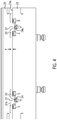
- Fig. 4 shows a vertical section through the lower part 24 of the sealing station 3. It can be seen here that the sliding blocks 32 are each supported in the lower part 24 by means of a helical compression spring 33 which pretensions the sliding blocks 32 upwards. When a sufficiently high force is exerted from above on the sealing glasses 28, the sliding blocks 32 move downward until their surface 32a is flush with the upper side 24a of the lower part 24. For each sliding block 32 there is one Guide 34 is provided in the lower part 24 in order to prevent tilting during the movement of the sliding block 32.
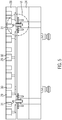
- Fig. 5 shows a vertical section through the lower part 24 and the sealing glasses 28 on the in Fig. 2 with VV.
- the openings 29, designed here as a recess, with their edges 30 in the sealing frame 28 can be seen. It can also be seen how the sealing frame 28 is placed on the bolt 31 protruding upward from the lower part 24, for which purpose corresponding recesses in the underside of the sealing frame 28 are provided.
- Fig. 6 shows the in Fig. 5 section marked VI.
- the bolt 31 is designed here as a screw and - surrounded by a bushing 35 - screwed into a recess 28 a in the sealing frame 28.
- the socket 35 comprises a collar 36.
- a plate 38 is inserted into a recess 37 in the lower part 24 of the sealing station 3 and is fastened there with countersunk screws 39.
- the plate 38 has an opening 40 through which the bolt 31 and its bushing 35 extend with a play S therethrough.
- the play S determines the maximum distance by which the sealing glasses 28 can shift in the horizontal direction relative to the lower part 24.
- the edge of the opening 40 thus represents a stop 41 for the horizontal movement of the sealing glasses 28.
- the collar 36 of the socket 35 additionally secures the sealing glasses 28 against lifting upwards from the lower part 24.
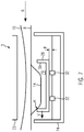
- Fig. 7 shows schematically how the floating mounting of the sealing glasses 28 in the lower part 24 affects the operation of the thermoforming packaging machine 1.
- the sealing station 3 is brought from its open position 26 shown here into its closed position 27.
- the upper part 23 and the lower part 24 are moved relative to one another, preferably by lifting the lower part 24 with the closing direction Z upwards.
- the sealing frame 28 rests loosely on the sliding blocks 32.
- the sealing glasses 28 will shift in the lateral direction R, Y as soon as they experience a force in one of these directions that is greater than the sliding friction between the sealing glasses 28 and the sliding blocks 32. This force is created by the contact at the point K between the trough 14 and the edge 30 of the opening 29 in the sealing frame 28.
- the sealing glasses 28 experience a displacement V (here: in the direction R to the left) when the lower part 24 and with it the sealing glasses 28 are raised further.
- This displacement V continues until the sealing glasses 28 bear against the edge of the troughs 14.
- the displacement according to the invention of the sealing glasses 28 will work better, the smaller the inertia of the sealing glasses 28, the slower the closing movement of the sealing station 3 and the lower the friction between the sealing glasses 28 and the lower part 24 of the sealing station 3, and the stronger (harder ) the lower film 8 is selected.
- the invention can be supplemented or modified in many ways. It has already been pointed out that, for example, the number and distribution of the openings 29 in the sealing glasses 28 can be largely freely selected. Measures to reduce the sliding friction between the sealing frame 28 and the lower part 24 can make it possible, in principle, to also use thinner packaging films.
Landscapes
- Engineering & Computer Science (AREA)
- Mechanical Engineering (AREA)
- Containers And Plastic Fillers For Packaging (AREA)
- Closing Of Containers (AREA)
Abstract
Die Erfindung bezieht sich auf eine Tiefziehverpackungsmaschine (1) und auf ein Verfahren zum Betreiben einer solchen Tiefziehverpackungsmaschine (1), bei denen im Unterteil (24) der Siegelstation (3) eine Siegelbrille (28) vorgesehen ist, die schwimmend im Unterteil (24) gelagert ist und sich infolgedessen während des Schließens der Siegelstation (3) relativ zum Unterteil (24) verlagern kann.
Description
- Die Erfindung bezieht sich auf ein Verfahren zum Betreiben einer Tiefziehverpackungsmaschine gemäß dem Oberbegriff des Anspruchs 1 und auf eine Tiefziehverpackungsmaschine selbst.
- Ein entsprechendes Verfahren zum Betreiben einer Tiefziehverpackungsmaschine ist beispielsweise aus der
EP 2 740 679 A1 bekannt. Diese herkömmliche Tiefziehverpackungsmaschine hat das Ziel, den Materialverbrauch der Verpackungsmaschine zu reduzieren, indem Toleranzen verringert werden. Zu diesem Zweck ist innerhalb einer Vorschublänge stromaufwärts der Siegelstation ein Messsystem vorgesehen, das die Lage der Mulden in der Unterfolie erfasst. Im nachfolgenden Arbeitstakt werden die entsprechenden Mulden in die Siegelstation transportiert und diese Siegelstation wird entsprechend der ermittelten Lage der Mulden präzise relativ zu der Position der Mulden positioniert. Prinzipiell kann dies erfordern, dass bei jedem Arbeitstakt der taktweise betriebenen Verpackungsmaschine die gesamte Siegelstation aktiv positioniert wird. - Die Aufgabe der vorliegenden Erfindung ist es, ein Verfahren und eine Tiefziehverpackungsmaschine der eingangs genannten Art dahingehend zu verbessern, dass der Materialverbrauch einer Verpackungsmaschine mit konstruktiv möglichst einfachen Mitteln verringert wird.
- Diese Aufgabe wird gelöst durch ein Verfahren mit den Merkmalen des Anspruchs 1 bzw. durch eine Tiefziehverpackungsmaschine mit den Merkmalen des Anspruchs 6. Vorteilhafte Weiterbildungen der Erfindung sind jeweils in den Unteransprüchen angegeben.
- Das erfindungsgemäße Verfahren dient zum Betreiben einer Tiefziehverpackungsmaschine, die eine Formstation zum Tiefziehen von Mulden in eine Unterfolie sowie eine Siegelstation zum Versiegeln der Mulden mit einer Oberfolie aufweist, wobei die Siegelstation typischerweise stromabwärts der Formstation angeordnet werden wird. Die Siegelstation weist ihrerseits ein Oberteil und ein Unterteil auf, von denen mindestens eines relativ zum anderen zwischen einer geöffneten Stellung und einer geschlossenen Stellung bewegbar ist. Diese Bewegung findet statt in einer sogenannten Schließrichtung, die häufig vertikal sein wird. Oft wird dabei der sogenannte Hub (d. h. der Bewegungsweg) des Unterteils größer sein als derjenige des Oberteils. Bei der Erfindung umfasst die Siegelstation ferner innerhalb des Unterteils eine Siegelbrille mit einer oder mehreren Öffnungen zur Aufnahme einer entsprechenden Anzahl von einer oder mehreren Mulden der Unterfolie.
- Im erfindungsgemäßen Verfahren werden die Mulden in der Formstation tiefgezogen und anschließend in einer Transportrichtung von der Formstation zur Siegelstation transportiert. Dieser Transport kann intermittierend (d. h. taktweise) erfolgen. Nachdem eine Mulde oder ein sogenanntes Format von mehreren Mulden in die Siegelstation eingebracht wurde, wird die Siegelstation geschlossen, indem Oberteil und/oder Unterteil der Siegelstation in der besagten Schließrichtung von der geöffneten zur geschlossenen Stellung gebracht werden.
- Die Erfindung zeichnet sich dadurch aus, dass die Siegelbrille während des Schließens der Siegelstation durch Verlagern relativ zum Unterteil in Transportrichtung und/oder in einer sowohl senkrecht zur Transportrichtung als auch senkrecht zur Schließrichtung stehenden Richtung an der oder den in die Siegelstation eingebrachten Mulden ausrichtet. Mit anderen Worten: Während sich das Unterteil der Siegelstation in Schließrichtung bewegt, bewegt sich die Siegelbrille relativ zum Unterteil in Transportrichtung und/oder quer zur Transportrichtung, so dass die Siegelbrille anschließend präzise relativ zu den Mulden positioniert ist. Auf diese Weise kann der Materialverbrauch der Tiefziehverpackungsmaschine gesenkt werden, da wegen der präzise relativ zu den Mulden ausgerichteten Siegelbrille mit geringeren Siegelnahtbreiten und/oder geringeren Abständen der Siegelung zu den jeweiligen Verpackungsmulden als in herkömmlichen Verpackungsmaschinen gearbeitet werden kann.
- Besonders vorteilhaft ist es, wenn sich die Siegelbrille gewissermaßen passiv relativ zum Unterteil verlagert, d. h. ohne einen aktiven Antrieb, im Gegensatz beispielsweise zur motorischen Verstellung der Siegelstation gemäß
EP 2 740 679 A1 . Bei der Erfindung kann dies dadurch geschehen, dass sich die Siegelbrille durch Kontakt eines Rands ihrer Öffnung mit der wenigstens einen Mulde ausrichtet. Dazu wäre es vorteilhaft, wenn die Widerstandskraft der Unterfolie gegen eine Verformung der Mulde mindestens so hoch oder sogar höher ist als die Kraft, die zum Verlagern der Siegelbrille erforderlich ist, beispielsweise um Reibungskräfte zu überwinden. - Eine Möglichkeit hierfür besteht in der Verwendung einer Unterfolie mit einer Stärke von mindestens 150 µm, vorzugsweise sogar wenigstens 300 µm oder 400 µm. Solche Folien werden oft als Hartfolie bezeichnet.
- Als zweckmäßig erweist es sich, wenn die Siegelbrille und das Unterteil der Siegelstation nach zumindest einem Teil der Schließbewegung der Siegelstation auf Block liegen. Zu diesem Zeitpunkt sind die für eine weitere Verlagerung der Siegelbrille erforderlichen Kräfte deutlich höher als zu Beginn der Schließbewegung. Dies ermöglicht eine Kontrolle der Position der Siegelbrille.
- Vorzugsweise behält die Siegelbrille nach einem Teil der Schließbewegung der Siegelstation relativ zum Unterteil ihre Position in Transportrichtung der Unterfolie und/oder in Querrichtung zur Transportrichtung bei. Wie bereits erwähnt, kann dies beispielsweise dadurch erreicht werden, dass die Siegelbrille und das Unterteil der Siegelstation nach der Schließbewegung oder zumindest einem Teil der Schließbewegung auf Block liegen.
- Die Erfindung bezieht sich auch auf eine Tiefziehverpackungsmaschine, die eine Formstation zum Tiefziehen von Mulden in eine Unterfolie sowie eine Siegelstation zum Versiegeln der Mulden mit einer Oberfolie aufweist, wobei die Siegelstation ein Oberteil und ein Unterteil umfasst, von denen wenigstens eines relativ zum anderen zwischen einer geöffneten Stellung und einer geschlossenen Stellung bewegbar ist. Die Siegelstation umfasst ferner innerhalb des Unterteils eine Siegelbrille mit einer oder mehreren Öffnungen zur Aufnahme einer entsprechenden Anzahl von Mulden. Diese Tiefziehverpackungsmaschine könnte zum Durchführen eines Verfahrens nach einer der vorstehend erläuterten Varianten konfiguriert sein.
- Die erfindungsgemäße Tiefziehverpackungsmaschine zeichnet sich dadurch aus, dass die Siegelbrille innerhalb des Unterteils der Siegelstation schwimmend gelagert ist und zumindest zeitweise während des Schließens der Siegelstation relativ zum Unterteil verlagerbar ist. Mit dieser schwimmenden Lagerung wird ermöglicht, dass sich die Siegelbrille während des Schließens der Siegelstation positionsgenau relativ zu der oder den Mulden in der Unterfolie ausrichtet, was wiederum die vorstehend erläuterten Vorteile hinsichtlich eines verringerten Materialverbrauchs der Verpackungsmaschine bietet.
- Günstig ist es in dieser Hinsicht, wenn die Siegelbrille relativ zum Unterteil der Siegelstation in einer oder zwei Raumrichtungen verlagerbar ist, die jeweils senkrecht zu einer Schließrichtung der Siegelstation oder konkret horizontal ausgerichtet sind. Bei diesen beiden Richtungen kann es sich insbesondere um eine Transportrichtung der Unterfolie in der Tiefziehverpackungsmaschine und um eine Richtung quer zu dieser Transportrichtung handeln. Mit anderen Worten ist die Siegelbrille beispielsweise in einem oder zwei Freiheitsgraden horizontal beweglich, während die Siegelstation eine Schließbewegung vollzieht, beispielsweise durch Anheben des Unterteils.
- In einer vorteilhaften Variante liegt die Siegelbrille auf mindestens einem in Unterteil der Siegelstation angeordneten oder gelagerten Gleitstein auf. Der Begriff "Gleitstein" ist dabei nicht einschränkend auf ein Steinmaterial zu verstehen, sondern bezeichnet jegliches Element, auf dem die Siegelbrille gleiten kann. In dieser Hinsicht kann der Gleitstein auch eine Gleitplatte sein. Der Gleitstein kann eine glatte, ebene, gekrümmte und/oder strukturierte Oberfläche aufweisen. Vorzugsweise sind zwei, drei, vier oder mehr Gleitsteine vorgesehen, um ein Verkannten der Siegelbrille im Unterteil zu verhindern.
- Als vorteilhaft hat es sich erwiesen, wenn der mindestens eine Gleitstein oder die mehreren Gleitsteine federnd im Unterteil der Siegelstation gelagert ist/sind. Dies trägt dazu bei, die Reibungskräfte zwischen Siegelbrille und Gleitstein zu verringern.
- Vorteilhaft ist es auch, wenn der mindestens eine Gleitstein im Unterteil der Siegelstation versenkbar gelagert ist. Dies ermöglicht es, dass die Siegelbrille bei einem genügend hohen Anpressdruck mit dem Unterteil der Siegelstation auf Block kommt, was dann eine weitere Verlagerung der Siegelbrille erschwert oder verhindert.
- Vorteilhaft ist es weiterhin, wenn der mindestens eine Gleitstein in einer Führung im Unterteil gelagert ist, um auf diese Weise ein Verkanten des Gleitsteins relativ zum Unterteil der Siegelstation zu verhindern.
- Vorzugsweise weist die Siegelstation einen Anschlag auf, ggf. auch mehrere Anschläge, um ein Ausmaß der Verlagerung der Siegelbrille in einer oder zwei Richtungen zu begrenzen. Auf diese Weise kann sichergestellt werden, dass sich die Siegelbrille lediglich innerhalb eines bestimmten Raumbereichs verlagert. Dies wiederum ist vorteilhaft, um sicherzustellen, dass die Siegelbrille auch bei nachfolgenden Arbeitstakten bereits einigermaßen genau zu den Mulden in der Unterfolie ausgerichtet ist.
- Denkbar ist es, dass die Siegelbrille auf mindestens einen nach oben aus dem Unterteil hervorstehenden Bolzen aufgesetzt ist, insbesondere lose aufgesetzt ist. In diesem Fall kann der Kontakt zwischen der Siegelbrille und dem Bolzen in Horizontalrichtung eine Möglichkeit zum Realisieren des vorstehend angesprochenen Anschlags darstellen.
- Konkret könnte der Bolzen mit Spiel in einer Öffnung der Siegelbrille oder in einer Öffnung im Unterteil aufgenommen sein, so dass beim Aufbrauchen dieses Spiels der besagte Anschlag stattfindet.
- Im Folgenden wird ein vorteilhaftes Ausführungsbeispiels der Erfindung anhand einer Zeichnung näher erläutert. Im Einzelnen zeigen:
- Figur 1
- eine schematische Ansicht einer erfindungsgemäßen Tiefziehverpackungsmaschine,
- Figur 2
- eine perspektivische Ansicht eines Teils des Siegelstation-Unterteils mit der Siegelbrille,
- Figur 3
- eine perspektivische Ansicht entsprechend
Fig. 2 , allerdings ohne die Siegelbrille, - Figur 4
- einen Vertikalschnitt durch Komponenten der Siegelstation, an der in
Fig. 2 mit V-V bezeichneten Stelle, - Figur 5
- einen Vertikalschnitt durch Komponenten der Siegelstation,
- Figur 6
- eine Ausschnittsvergrößerung aus
Fig. 5 , und - Figur 7
- eine schematische Zeichnung des Funktionsprinzips.
- Einander entsprechende Komponenten sind in den Figuren durchgängig mit gleichem Bezugszeichen versehen.
-
Figur 1 zeigt in schematischer Ansicht eine erfindungsgemäße Verpackungsmaschine in Form einer Tiefziehverpackungsmaschine 1. Die Tiefziehverpackungsmaschine 1 weist eine Formstation 2, eine Siegelstation 3, eine Querschneidestation 4 und eine Längsschneidestation 5 auf, die in dieser Reihenfolge in eine Arbeitsrichtung oder Transportrichtung R an einem Maschinengestell 6 angeordnet sind. Eingangsseitig befindet sich an dem Maschinengestell 6 eine Zufuhrrolle 7, von der eine Unterfolie 8 abgezogen wird. Im Bereich der Siegelstation 3 ist ein Materialspeicher 9 vorgesehen, von dem eine Oberfolie 10 abgezogen wird. Ausgangsseitig ist an der Verpackungsmaschine eine Abfuhreinrichtung 13 in Form eines Transportbandes vorgesehen, mit der fertige, vereinzelte Verpackungen 21 abtransportiert werden. Ferner weist die Verpackungsmaschine 1 eine nicht dargestellte Vorschubeinrichtung auf, die die Unterfolie 8 ergreift und in einem Hauptarbeitstakt taktweise in der Arbeitsrichtung R weitertransportiert. Die Vorschubeinrichtung kann zum Beispiel durch seitlich angeordnete Transportketten realisiert sein und die Unterfolie 8 in einer Transportebene E transportieren. - In der dargestellten Ausführungsform ist die Formstation 2 als eine Tiefziehstation ausgebildet, in der in der Unterfolie 8 durch Tiefziehen Mulden 14 geformt werden. Dabei kann die Formstation 2 derart ausgebildet sein, dass in der Richtung senkrecht zur Transportrichtung R mehrere Mulden nebeneinander gebildet werden. In Transportrichtung R hinter der Formstation 2 ist eine Einlegestrecke 15 vorgesehen, in der die in der Unterfolie 8 geformten Mulden 14 mit Produkten 16 befüllt werden.
- Die Siegelstation 3 verfügt über eine verschließbare Kammer 17, in der die Atmosphäre in der Mulde 14 vor dem Versiegeln zum Beispiel durch Gasspülen mit einem Austauschgas oder mit einem Austausch-Gasgemisch ersetzt werden kann.
- Die Querschneidestation 4 ist als Streifenstanze ausgebildet, die die Unterfolie 8 und die Oberfolie 10 in einer Richtung quer zur Arbeitsrichtung R zwischen benachbarten Mulden 14 durchtrennt. Dabei arbeitet die Querschneidestation 4 derart, dass die Unterfolie 8 nicht über die gesamte Breite aufgetrennt wird, sondern zumindest in einem Randbereich und zwischen zwei benachbarten Mulden 14 nicht durchtrennt wird. Dies ermöglicht einen kontrollierten Weitertransport der Mulden 14 durch die Vorschubeinrichtung.
- Die Längsschneidestation 5 ist in der dargestellten Ausführungsform als eine Messeranordnung ausgebildet, mit der die Unterfolie 8 und die Oberfolie 10 zwischen benachbarten Mulden 14 und am seitlichen Rand der Unterfolie 8 durchtrennt werden, so dass hinter der Längsschneidestation 5 vereinzelte Verpackungen 21 vorliegen.
- Die Verpackungsmaschine 1 verfügt ferner über eine Steuerung 18. Sie hat die Aufgabe, die in der Verpackungsmaschine 1 ablaufenden Prozesse zu steuern und zu überwachen. Eine Anzeigevorrichtung 19 mit Bedienelementen 20 dient zum Visualisieren bzw. Beeinflussen der Prozessabläufe in der Tiefziehverpackungsmaschine 1 für bzw. durch einen Bediener.
- Die generelle Arbeitsweise der Verpackungsmaschine 1 wird im Folgenden kurz dargestellt.
- Die Unterfolie 8 wird von der Zufuhrrolle 7 abgezogen und durch die Vorschubeinrichtung in die Formstation 2 transportiert. In der Formstation 2 werden durch Tiefziehen Mulden 14 in die Unterfolie 8 gebildet. Die Mulden 14 werden zusammen mit dem umgebenden Bereich der Unterfolie 8 in einem Hauptarbeitstakt zu der Einlegestrecke 15 weitertransportiert, in der sie mit Produkt 16 befüllt werden.
- Anschließend werden die befüllten Mulden 14 zusammen mit dem sie umgebenden Bereich der Unterfolie 8 in dem Hauptarbeitstakt durch die Vorschubeinrichtung in Transportrichtung R in die Siegelstation 3 weitertransportiert. Die Oberfolie 10 wird nach einem Ansiegelvorgang an die Unterfolie 8 mit der Vorschubbewegung der Unterfolie 8 weitertransportiert. Dabei wird die Oberfolie 10 von dem Materialspeicher 9 abgezogen. Durch das Ansiegeln der Oberfolie 10 an die Mulden 14 entstehen verschlossene Verpackungen 21.
- Die Siegelstation 3 verfügt über ein Oberwerkzeug bzw. Oberteil 23 und ein Unterwerkzeug bzw. Unterteil 24. Mindestens eines dieser Ober- und Unterteile 23, 24 ist mittels einer Hubeinrichtung 25 in einer Schließrichtung Z beweglich, die senkrecht zur Transportrichtung R steht und vorzugsweise vertikal sein kann. Konkret ist das oder sind die beweglichen Ober- bzw. Unterteil 23, 24 in Schließrichtung Z derart relativ zum anderen Ober-/Unterteil 23, 24 beweglich, dass sie zwischen einer in
Fig. 1 mit gestrichelten Linien angedeuteten, geöffneten Stellung 26 und einer mit durchgezogenen Linien gezeigten, geschlossenen Stellung 27 bewegbar sind, wobei die Ober- und Unterteile 23, 24 in der geschlossenen Stellung 27 zwischen sich die hermetisch geschlossene Kammer 17 bilden. - Innerhalb der Unterteils 24 der Siegelstation 3 ist eine Siegelbrille 28 angeordnet.
Fig. 2 zeigt die Siegelbrille 28 über einem Teil der Komponenten des Unterteils 24 der Siegelstation 3. Im dargestellten Ausführungsbeispiel ist die Siegelbrille 28 plattenförmig konfiguriert. Sie kann zur Aufnahme einer oder mehrerer Mulden 14 eine oder mehrere Öffnungen 29 aufweisen, die in Form von Durchgangsöffnungen oder von Vertiefungen in der Siegelbrille 28 ausgebildet sein können. Die Zahl und die Anordnung der Öffnungen 29 in der Siegelbrille 28 sollte an die Zahl und die räumliche Verteilung der in der Formstation 2 erzeugten Mulden 14 in der Unterfolie 8 angepasst sein. Im Ausführungsbeispiel nachFig. 2 weist die Siegelbrille 28 insgesamt 72 solcher Öffnungen 29 auf. Jede Öffnung 29 hat hier einen umlaufenden Rand 30. -
Fig. 3 zeigt dieselbe perspektivische Ansicht wieFig. 2 , allerdings ohne die Siegelbrille 28. Von einer Oberseite 24a, die zum Unterteil 24 gehört, stehen Bolzen 31 nach oben hervor. Im vorliegenden Ausführungsbeispiel gibt es vier solcher Bolzen 331. Auf diese Stifte oder Bolzen 31 kann die Siegelbrille 28 lose, d. h. mit Spiel, in einer oder zwei der Richtungen R, Y (d. h. jeweils senkrecht zur Schließrichtung Z) aufgesetzt werden. - Im Unterteil 24 sind ferner ein oder mehrere (im vorliegenden Ausführungsbeispiel: vier) Gleitelemente oder Gleitsteine 32 angeordnet. Im vorliegenden Ausführungsbeispiel sind die Gleitsteine 32 jeweils federnd im Unterteil 24 gelagert. Sie ragen in der in
Fig. 3 gezeigten Stellung mit ihrer Oberseite 32a über die Oberseite 24a des Unterteils 24 hinaus. Die Oberfläche 32a der Gleitsteine 32 ist hier eben; auf den Oberflächen 32a der Gleitsteine 32 liegt die Siegelbrille 28 lose, d. h. verschiebbar, auf. -
Fig. 4 zeigt einen Vertikalschnitt durch das Unterteil 24 der Siegelstation 3. Zu erkennen ist hier, dass die Gleitsteine 32 jeweils mittels einer schraubenförmigen Druckfeder 33, die die Gleitsteine 32 nach oben vorspannt, im Unterteil 24 gelagert sind. Beim Ausüben einer genügend hohen Kraft von oben auf die Siegelbrille 28 verlagern sich die Gleitsteine 32 nach unten, bis ihre Oberfläche 32a flächenbündig ist mit der Oberseite 24a des Unterteils 24. Für jeden Gleitstein 32 ist eine Führung 34 im Unterteil 24 vorgesehen, um bei der Bewegung des Gleitsteins 32 ein Verkanten zu verhindern. -
Fig. 5 zeigt einen Vertikalschnitt durch das Unterteil 24 und die Siegelbrille 28 an der inFig. 2 mit V-V bezeichneten Stelle. Zu erkennen sind die hier als Vertiefung gestalteten Öffnungen 29 mit ihren Rändern 30 in der Siegelbrille 28. Zu erkennen ist auch, wie die Siegelbrille 28 auf die aus dem Unterteil 24 nach oben herausragenden Bolzen 31 aufgesetzt ist, wofür entsprechende Aussparungen in der Unterseite der Siegelbrille 28 vorgesehen sind. -
Fig. 6 zeigt in Vergrößerung den inFig. 5 mit VI bezeichneten Ausschnitt. Der Bolzen 31 ist hier als Schraube ausgebildet und - von einer Buchse 35 umgeben - in eine Aussparung 28a in der Siegelbrille 28 eingeschraubt. Die Buchse 35 umfasst einen Kragen 36. In eine Vertiefung 37 im Unterteil 24 der Siegelstation 3 ist eine Platte 38 eingelegt und dort mit Senkschrauben 39 befestigt. Die Platte 38 weist eine Öffnung 40 auf, durch die sich der Bolzen 31 und seine Buchse 35 mit einem Spiel S hindurch erstrecken. Das Spiel S bestimmt, um welchen maximalen Weg sich die Siegelbrille 28 in horizontaler Richtung relativ zum Unterteil 24 verlagern kann. Der Rand der Öffnung 40 stellt somit einen Anschlag 41 für die horizontale Bewegung der Siegelbrille 28 dar. Der Kragen 36 der Buchse 35 sichert die Siegelbrille 28 zusätzlich gegen ein Abheben nach oben vom Unterteil 24. -
Fig. 7 zeigt schematisch, wie sich die schwimmende Lagerung der Siegelbrille 28 im Unterteil 24 im Betrieb der Tiefziehverpackungsmaschine 1 auswirkt. Nachdem die Unterfolie 8 mit der mindestens einen Mulde 14 in Transportrichtung R in die Siegelstation hineintransportiert wurde, wird die Siegelstation 3 von ihrer hier dargestellten, geöffneten Stellung 26 in ihre geschlossene Stellung 27 gebracht. Zu diesem Zweck werden Oberteil 23 und Unterteil 24 relativ zueinander bewegt, vorzugsweise durch Anheben des Unterteils 24 mit Schließrichtung Z nach oben. Zumindest in einer ersten Phase der Schließbewegung liegt die Siegelbrille 28 lose auf den Gleitsteinen 32 auf. Die Siegelbrille 28 wird sich also in seitlicher Richtung R, Y verlagern, sobald sie in einer dieser Richtungen eine Kraft erfährt, die größer ist als die Gleitreibung zwischen der Siegelbrille 28 und den Gleitsteinen 32. Diese Kraft entsteht durch den Kontakt an der Stelle K zwischen der Mulde 14 und dem Rand 30 der Öffnung 29 in der Siegelbrille 28. - Folglich erfährt die Siegelbrille 28 eine Verlagerung V (hier: in Richtung R nach links), wenn das Unterteil 24 und mit ihm die Siegelbrille 28 weiter angehoben werden. Diese Verlagerung V setzt sich fort, bis die Siegelbrille 28 am Rand der Mulden 14 anliegt. Eine nun von oben auf die Siegelbrille 28 ausgeübte Kraft, beispielsweise durch das Oberteil 23, führt zu einem Verdrängen der federnd gelagerten Gleitsteine 32 in das Unterteil 24 hinein, bis der Spalt P zwischen Unterteil 24 und Siegelbrille 28 (siehe auch
Fig. 4 ) geschlossen wird und die Siegelbrille 28 auf Block liegt mit dem Unterteil 24. Ab diesem Zeitpunkt wird sich die Siegelbrille 28 nicht mehr seitlich verlagern. Sie kann jetzt die durch ein von oben herunterfahrendes Siegelwerkzeug einwirkenden Kräfte aufnehmen. - Die erfindungsgemäße Verlagerung der Siegelbrille 28 wird umso besser funktionieren, je kleiner die Massenträgheit der Siegelbrille 28, je langsamer die Schließbewegung der Siegelstation 3 und je geringer die Reibung zwischen der Siegelbrille 28 und dem Unterteil 24 der Siegelstation 3 gestaltet wird, und je stärker (härter) die Unterfolie 8 gewählt wird.
- Ausgehend von dem dargestellten Ausführungsbeispiel kann die Erfindung in vielfacher Weise ergänzt oder abgewandelt werden. So wurde bereits darauf hingewiesen, dass beispielsweise die Anzahl und die Verteilung der Öffnungen 29 in der Siegelbrille 28 weitgehend frei wählbar ist. Maßnahmen zur Verringerung der Gleitreibung zwischen Siegelbrille 28 und Unterteil 24 können es ermöglichen, prinzipiell auch dünnere Verpackungsfolien einzusetzen.
Claims (14)
- Verfahren zum Betreiben einer Tiefziehverpackungsmaschine (1), wobei die Tiefziehverpackungsmaschine (1) eine Formstation (2) zum Tiefziehen von Mulden (14) in eine Unterfolie (8) sowie eine Siegelstation (3) zum Versiegeln der Mulden (14) mit einer Oberfolie (10) aufweist,
wobei die Siegelstation (3) ein Oberteil (23) und ein Unterteil (24) aufweist, von denen mindestens eines relativ zum anderen zwischen einer geöffneten Stellung (26) und einer geschlossenen Stellung (27) bewegbar ist, und wobei die Siegelstation (3) innerhalb des Unterteils (24) eine Siegelbrille (28) mit einer oder mehreren Öffnungen (29) zur Aufnahme einer entsprechenden Anzahl von Mulden (14) umfasst,
wobei das Verfahren folgende Schritte aufweist:Tiefziehen von Mulden (14) in der Formstation (2),Transportieren der geformten Mulden (14) in einer Transportrichtung (R) von der Formstation (2) zur Siegelstation (3),Schließen der Siegelstation (3) durch Bewegen des Oberteils (23) und/oder des Unterteils (24) der Siegelstation (3) in einer zur Transportrichtung (R) senkrechten Schließrichtung (Z) von der geöffneten Stellung (26) zur geschlossenen Stellung (27),dadurch gekennzeichnet, dass sich die Siegelbrille (28) während des Schließens der Siegelstation (3) durch Verlagern relativ zum Unterteil (23) in Transportrichtung (R) und/oder in einer sowohl senkrecht zur Transportrichtung (R) als auch senkrecht zur Schließrichtung (Z) stehenden Richtung (Y) an der oder den in die Siegelstation (3) eingebrachten Mulden (14) ausrichtet. - Verfahren nach Anspruch 1, dadurch gekennzeichnet, dass die Siegelbrille (28) sich durch einen Kontakt eines Rands (30) der Öffnung (29) mit der wenigstens einen Mulde (14) ausrichtet.
- Verfahren nach einem der vorangehenden Ansprüche, dadurch gekennzeichnet, dass die Unterfolie (8) eine Stärke von 150µm oder mehr aufweist.
- Verfahren nach einem der vorangehenden Ansprüche, dadurch gekennzeichnet, dass die Siegelbrille (28) und das Unterteil (23) der Siegelstation (3) nach einem Teil der Schließbewegung der Siegelstation (3) auf Block liegen.
- Verfahren nach einem der vorangehenden Ansprüche, dadurch gekennzeichnet, dass die Siegelbrille (28) nach einem Teil der Schließbewegung der Siegelstation (3) relativ zum Unterteil (24) der Siegelstation (3) ihre Position in Transportrichtung (R) und in Richtung (Y) beibehält.
- Tiefziehverpackungsmaschine (1), insbesondere zum Durchführen eines Verfahrens nach einem der vorangehenden Ansprüche, wobei die Tiefziehverpackungsmaschine (1) eine Formstation (2) zum Tiefziehen von Mulden (14) in eine Unterfolie (8) sowie eine Siegelstation (3) zum Versiegeln der Mulden (14) mit einer Oberfolie (10) aufweist, wobei die Siegelstation (3) ein Oberteil (23) und ein Unterteil (24) aufweist, von denen mindestens eines relativ zum anderen zwischen einer geöffneten Stellung (26) und einer geschlossenen Stellung (27) bewegbar ist, und wobei die Siegelstation (3) innerhalb des Unterteils (24) eine Siegelbrille (28) mit einer oder mehreren Öffnungen (29) zur Aufnahme einer entsprechenden Anzahl von Mulden (14) umfasst, dadurch gekennzeichnet, dass die Siegelbrille (28) innerhalb des Unterteils (24) der Siegelstation (3) schwimmend gelagert ist und zumindest zeitweise während des Schließens der Siegelstation (3) relativ zum Unterteil (24) verlagerbar ist.
- Tiefziehverpackungsmaschine nach Anspruch 6, dadurch gekennzeichnet, dass die Siegelbrille (28) relativ zum Unterteil (24) der Siegelstation (3) in einer oder zwei Richtungen (R, Y) verlagerbar ist, die jeweils senkrecht zu einer Schließrichtung (Z) der Siegelstation (3) oder horizontal ausgerichtet sind.
- Tiefziehverpackungsmaschine nach einem der Ansprüche 6 oder 7, dadurch gekennzeichnet, dass die Siegelbrille (28) auf mindestens einem im Unterteil (24) der Siegelstation (3) angeordneten oder gelagerten Gleitstein (32) aufliegt.
- Tiefziehverpackungsmaschine nach Anspruch 8, dadurch gekennzeichnet, dass der mindestens eine Gleitstein (32) federnd im Unterteil (24) gelagert ist.
- Tiefziehverpackungsmaschine nach einem der Ansprüche 8 oder 9, dadurch gekennzeichnet, dass der mindestens eine Gleitstein (32) im Unterteil (24) versenkbar gelagert ist.
- Tiefziehverpackungsmaschine nach einem der Ansprüche 8 bis 10, dadurch gekennzeichnet, dass der mindestens eine Gleitstein (32) in einer Führung (34) im Unterteil (24) gelagert ist.
- Tiefziehverpackungsmaschine nach einem der Ansprüche 6 bis 11, dadurch gekennzeichnet, dass die Siegelstation (3) einen Anschlag (41) aufweist, um ein Ausmaß der Verlagerung der Siegelbrille (28) in einer oder zwei Richtungen (R, Y) zu begrenzen.
- Tiefziehverpackungsmaschine nach einem der Ansprüche 6 bis 12, dadurch gekennzeichnet, dass die Siegelbrille (28) auf mindestens einen nach oben aus dem Unterteil (24) hervorstehenden Bolzen (31) aufgesetzt ist.
- Tiefziehverpackungsmaschine nach Anspruch 13, dadurch gekennzeichnet, dass der Bolzen (31) mit Spiel (S) in einer Öffnung (40) in der Siegelbrille (28) oder im Unterteil (24) aufgenommen ist.
Applications Claiming Priority (1)
| Application Number | Priority Date | Filing Date | Title |
|---|---|---|---|
| DE102019218756.0A DE102019218756A1 (de) | 2019-12-03 | 2019-12-03 | Tiefziehverpackungsmaschine und Verfahren zum Betreiben einer Tiefziehverpackungsmaschine |
Publications (1)
| Publication Number | Publication Date |
|---|---|
| EP3831579A1 true EP3831579A1 (de) | 2021-06-09 |
Family
ID=74103808
Family Applications (1)
| Application Number | Title | Priority Date | Filing Date |
|---|---|---|---|
| EP20210089.7A Withdrawn EP3831579A1 (de) | 2019-12-03 | 2020-11-26 | Tiefziehverpackungsmaschine und verfahren zum betreiben einer tiefziehverpackungsmaschine |
Country Status (3)
| Country | Link |
|---|---|
| EP (1) | EP3831579A1 (de) |
| CN (1) | CN214190369U (de) |
| DE (1) | DE102019218756A1 (de) |
Citations (3)
| Publication number | Priority date | Publication date | Assignee | Title |
|---|---|---|---|---|
| FR2481641A1 (fr) * | 1980-04-30 | 1981-11-06 | Realisa Chaines Automatiq Et | Procede et dispositif de soudure d'une feuille de couvercle sur un recipient en matiere thermoplastique et recipient ainsi realise |
| GB1603542A (en) * | 1977-02-18 | 1981-11-25 | Gatrun Anstalt | Container made of thermoplastic material |
| EP2740679A1 (de) | 2012-12-04 | 2014-06-11 | Multivac Sepp Haggenmüller GmbH & Co. KG | Tiefziehverpackungsmaschine mit taktgenauer Positionierung einer Siegelstation und entsprechendes Verfahren |
Family Cites Families (9)
| Publication number | Priority date | Publication date | Assignee | Title |
|---|---|---|---|---|
| DE2252927C2 (de) * | 1972-10-27 | 1974-10-31 | Eugen 7000 Stuttgart Schierle | Vorrichtung zum Verschließen von Schalen mit Aluminiumfolie o.dgl |
| DE3011627A1 (de) * | 1980-03-26 | 1981-10-01 | Krämer & Grebe GmbH & Co KG Maschinen- und Modellfabrik, 3560 Biedenkopf | Schweisssiegelstation fuer verpackungsmaschinen |
| DE4326233A1 (de) * | 1993-08-05 | 1995-02-09 | Luebbers Maschinen Gmbh | Antrieb für eine Vorrichtung zum Verschließen und Trennen einer Verpackungsfolie u. ä. an Verpackungsmaschinen |
| US6499271B1 (en) * | 1996-04-08 | 2002-12-31 | Oliver Products Company | Tray sealing machine |
| DE102005006783B4 (de) * | 2005-02-14 | 2006-10-12 | Uhlmann Pac-Systeme Gmbh & Co Kg | Arbeitsstation |
| DE102010019729A1 (de) * | 2010-05-07 | 2011-11-10 | Multivac Sepp Haggenmüller Gmbh & Co. Kg | Arbeitsstation für Verpackungsmaschine |
| EP2570351B1 (de) * | 2011-09-16 | 2015-03-25 | Multivac Sepp Haggenmüller GmbH & Co. KG | Tiefziehverpackungsmaschine zum Herstellen von Standpackungen mit geformtem Hinterschnitt |
| ES2646768T3 (es) * | 2013-02-22 | 2017-12-15 | Multivac Sepp Haggenmüller Se & Co. Kg | Máquina de envasado por embutición profunda con estación de sellado y procedimiento |
| DE102018214666A1 (de) * | 2018-08-29 | 2020-03-05 | Multivac Sepp Haggenmüller Se & Co. Kg | Verfahren zum Verpacken von Produkten und Tiefziehverpackungsmaschine |
-
2019
- 2019-12-03 DE DE102019218756.0A patent/DE102019218756A1/de active Pending
-
2020
- 2020-11-26 EP EP20210089.7A patent/EP3831579A1/de not_active Withdrawn
- 2020-12-02 CN CN202022874010.1U patent/CN214190369U/zh active Active
Patent Citations (3)
| Publication number | Priority date | Publication date | Assignee | Title |
|---|---|---|---|---|
| GB1603542A (en) * | 1977-02-18 | 1981-11-25 | Gatrun Anstalt | Container made of thermoplastic material |
| FR2481641A1 (fr) * | 1980-04-30 | 1981-11-06 | Realisa Chaines Automatiq Et | Procede et dispositif de soudure d'une feuille de couvercle sur un recipient en matiere thermoplastique et recipient ainsi realise |
| EP2740679A1 (de) | 2012-12-04 | 2014-06-11 | Multivac Sepp Haggenmüller GmbH & Co. KG | Tiefziehverpackungsmaschine mit taktgenauer Positionierung einer Siegelstation und entsprechendes Verfahren |
Also Published As
| Publication number | Publication date |
|---|---|
| DE102019218756A1 (de) | 2021-06-10 |
| CN214190369U (zh) | 2021-09-14 |
Similar Documents
| Publication | Publication Date | Title |
|---|---|---|
| EP2207653B1 (de) | Schneidemaschine zum schneiden von materialblöcken | |
| DE102011115142B4 (de) | Verfahren zum Vereinzeln von Verpackungen | |
| EP0538570A1 (de) | Vorrichtung zum Herstellen einer Verpackung | |
| EP2008736A1 (de) | Werkzeugmaschine und Verfahren zum Ausschleusen eines Werkstückteils | |
| EP1598276A1 (de) | Verpackungsmaschine und Verfahren zum Schneiden von Packungen | |
| EP2985234B1 (de) | Tiefziehverpackungsmaschine mit bewegbarem Formeinsatz | |
| EP1018408B1 (de) | Planschneidmaschine zum Schneiden von gestapeltem, blattförmigem Gut | |
| EP3790681B1 (de) | Vorrichtung und verfahren zum heraustrennen eines werkstücks | |
| DE60119214T2 (de) | Vorrichtung zum Schneiden von Blisterverpackungen in einer Blisterverpackungsmaschine | |
| EP3088315B2 (de) | Tiefziehverpackungsmaschine mit streifenstanze | |
| EP2481540B1 (de) | Einrichtung zum Zersägen von zumindest zwei platten- oder plattenstapelförmigen Werkstücken | |
| DE3149621A1 (de) | Stanzvorrichtung | |
| DE2921176A1 (de) | Schlag- oder stanzeinrichtung | |
| EP1782930B1 (de) | Vorrichtung zum Beschneiden von Druckprodukten | |
| DE2740674C2 (de) | Kreissägemaschine für Platten, Plattenpakete od. dgl. | |
| DE1940912C3 (de) | Vorrichtung zum Ausrichten von schrittweise einer Schere mit Scrollschnitt zugeführtem Bandmaterial | |
| EP1877233A2 (de) | Vorrichtung zum trennen eines plastischen tonstranges, mit einer allseitig wirksamen kerbvorrichtung | |
| DE102019218756A1 (de) | Tiefziehverpackungsmaschine und Verfahren zum Betreiben einer Tiefziehverpackungsmaschine | |
| DE102014210867B4 (de) | Platinenschneidwerkzeug mit mehreren Schneidstationen | |
| DE202018002305U1 (de) | Vorrichtung zum Heraustrennen eines Werkstücks | |
| EP1555096B1 (de) | Gegenwerkzeug zum Schneiden von bahnartigem Material sowie Verfahren zur Erzeugung von Querschnitten in einem bahnartigen Material mit einem solchen Gegenwerkzeug | |
| DE102018003622A1 (de) | Vorrichtung und Verfahren zum Heraustrennen eines Werkstücks | |
| DE2654000B2 (de) | Maschine zum Ausbrechen von Nutzen | |
| DE102021109656A1 (de) | Trennstation für eine verpackungsmaschine | |
| DE4242373A1 (en) | Appts. for cutting fabric laminates accurately |
Legal Events
| Date | Code | Title | Description |
|---|---|---|---|
| PUAI | Public reference made under article 153(3) epc to a published international application that has entered the european phase |
Free format text: ORIGINAL CODE: 0009012 |
|
| STAA | Information on the status of an ep patent application or granted ep patent |
Free format text: STATUS: THE APPLICATION HAS BEEN PUBLISHED |
|
| AK | Designated contracting states |
Kind code of ref document: A1 Designated state(s): AL AT BE BG CH CY CZ DE DK EE ES FI FR GB GR HR HU IE IS IT LI LT LU LV MC MK MT NL NO PL PT RO RS SE SI SK SM TR |
|
| STAA | Information on the status of an ep patent application or granted ep patent |
Free format text: STATUS: THE APPLICATION IS DEEMED TO BE WITHDRAWN |
|
| 18D | Application deemed to be withdrawn |
Effective date: 20211210 |