EP2985234B1 - Tiefziehverpackungsmaschine mit bewegbarem Formeinsatz - Google Patents
Tiefziehverpackungsmaschine mit bewegbarem Formeinsatz Download PDFInfo
- Publication number
- EP2985234B1 EP2985234B1 EP14180776.8A EP14180776A EP2985234B1 EP 2985234 B1 EP2985234 B1 EP 2985234B1 EP 14180776 A EP14180776 A EP 14180776A EP 2985234 B1 EP2985234 B1 EP 2985234B1
- Authority
- EP
- European Patent Office
- Prior art keywords
- mold
- film
- mold insert
- forming tool
- packaging machine
- Prior art date
- Legal status (The legal status is an assumption and is not a legal conclusion. Google has not performed a legal analysis and makes no representation as to the accuracy of the status listed.)
- Active
Links
- 238000004806 packaging method and process Methods 0.000 title claims description 30
- 238000003856 thermoforming Methods 0.000 claims description 21
- 238000000034 method Methods 0.000 claims description 15
- 239000010408 film Substances 0.000 description 43
- 238000004519 manufacturing process Methods 0.000 description 7
- 238000007789 sealing Methods 0.000 description 7
- 238000005520 cutting process Methods 0.000 description 6
- 230000032258 transport Effects 0.000 description 6
- 230000002093 peripheral effect Effects 0.000 description 3
- 239000013039 cover film Substances 0.000 description 2
- 238000003780 insertion Methods 0.000 description 2
- 230000037431 insertion Effects 0.000 description 2
- 239000000463 material Substances 0.000 description 2
- 238000000465 moulding Methods 0.000 description 2
- 238000010276 construction Methods 0.000 description 1
- 238000001816 cooling Methods 0.000 description 1
- 238000011161 development Methods 0.000 description 1
- 230000018109 developmental process Effects 0.000 description 1
- 239000011888 foil Substances 0.000 description 1
- 239000000203 mixture Substances 0.000 description 1
- 238000010926 purge Methods 0.000 description 1
- 238000003860 storage Methods 0.000 description 1
Images


Classifications
-
- B—PERFORMING OPERATIONS; TRANSPORTING
- B29—WORKING OF PLASTICS; WORKING OF SUBSTANCES IN A PLASTIC STATE IN GENERAL
- B29C—SHAPING OR JOINING OF PLASTICS; SHAPING OF MATERIAL IN A PLASTIC STATE, NOT OTHERWISE PROVIDED FOR; AFTER-TREATMENT OF THE SHAPED PRODUCTS, e.g. REPAIRING
- B29C51/00—Shaping by thermoforming, i.e. shaping sheets or sheet like preforms after heating, e.g. shaping sheets in matched moulds or by deep-drawing; Apparatus therefor
- B29C51/26—Component parts, details or accessories; Auxiliary operations
- B29C51/261—Handling means, e.g. transfer means, feeding means
-
- B—PERFORMING OPERATIONS; TRANSPORTING
- B65—CONVEYING; PACKING; STORING; HANDLING THIN OR FILAMENTARY MATERIAL
- B65B—MACHINES, APPARATUS OR DEVICES FOR, OR METHODS OF, PACKAGING ARTICLES OR MATERIALS; UNPACKING
- B65B47/00—Apparatus or devices for forming pockets or receptacles in or from sheets, blanks, or webs, comprising essentially a die into which the material is pressed or a folding die through which the material is moved
- B65B47/08—Apparatus or devices for forming pockets or receptacles in or from sheets, blanks, or webs, comprising essentially a die into which the material is pressed or a folding die through which the material is moved by application of fluid pressure
- B65B47/10—Apparatus or devices for forming pockets or receptacles in or from sheets, blanks, or webs, comprising essentially a die into which the material is pressed or a folding die through which the material is moved by application of fluid pressure by vacuum
-
- B—PERFORMING OPERATIONS; TRANSPORTING
- B29—WORKING OF PLASTICS; WORKING OF SUBSTANCES IN A PLASTIC STATE IN GENERAL
- B29C—SHAPING OR JOINING OF PLASTICS; SHAPING OF MATERIAL IN A PLASTIC STATE, NOT OTHERWISE PROVIDED FOR; AFTER-TREATMENT OF THE SHAPED PRODUCTS, e.g. REPAIRING
- B29C51/00—Shaping by thermoforming, i.e. shaping sheets or sheet like preforms after heating, e.g. shaping sheets in matched moulds or by deep-drawing; Apparatus therefor
- B29C51/18—Thermoforming apparatus
-
- B—PERFORMING OPERATIONS; TRANSPORTING
- B65—CONVEYING; PACKING; STORING; HANDLING THIN OR FILAMENTARY MATERIAL
- B65B—MACHINES, APPARATUS OR DEVICES FOR, OR METHODS OF, PACKAGING ARTICLES OR MATERIALS; UNPACKING
- B65B31/00—Packaging articles or materials under special atmospheric or gaseous conditions; Adding propellants to aerosol containers
- B65B31/02—Filling, closing, or filling and closing, containers or wrappers in chambers maintained under vacuum or superatmospheric pressure or containing a special atmosphere, e.g. of inert gas
- B65B31/021—Filling, closing, or filling and closing, containers or wrappers in chambers maintained under vacuum or superatmospheric pressure or containing a special atmosphere, e.g. of inert gas the containers or wrappers being interconnected
-
- B—PERFORMING OPERATIONS; TRANSPORTING
- B65—CONVEYING; PACKING; STORING; HANDLING THIN OR FILAMENTARY MATERIAL
- B65B—MACHINES, APPARATUS OR DEVICES FOR, OR METHODS OF, PACKAGING ARTICLES OR MATERIALS; UNPACKING
- B65B31/00—Packaging articles or materials under special atmospheric or gaseous conditions; Adding propellants to aerosol containers
- B65B31/02—Filling, closing, or filling and closing, containers or wrappers in chambers maintained under vacuum or superatmospheric pressure or containing a special atmosphere, e.g. of inert gas
- B65B31/025—Filling, closing, or filling and closing, containers or wrappers in chambers maintained under vacuum or superatmospheric pressure or containing a special atmosphere, e.g. of inert gas specially adapted for rigid or semi-rigid containers
- B65B31/028—Filling, closing, or filling and closing, containers or wrappers in chambers maintained under vacuum or superatmospheric pressure or containing a special atmosphere, e.g. of inert gas specially adapted for rigid or semi-rigid containers closed by a lid sealed to the upper rim of the container, e.g. tray-like container
-
- B—PERFORMING OPERATIONS; TRANSPORTING
- B65—CONVEYING; PACKING; STORING; HANDLING THIN OR FILAMENTARY MATERIAL
- B65B—MACHINES, APPARATUS OR DEVICES FOR, OR METHODS OF, PACKAGING ARTICLES OR MATERIALS; UNPACKING
- B65B9/00—Enclosing successive articles, or quantities of material, e.g. liquids or semiliquids, in flat, folded, or tubular webs of flexible sheet material; Subdividing filled flexible tubes to form packages
- B65B9/02—Enclosing successive articles, or quantities of material between opposed webs
- B65B9/04—Enclosing successive articles, or quantities of material between opposed webs one or both webs being formed with pockets for the reception of the articles, or of the quantities of material
-
- B—PERFORMING OPERATIONS; TRANSPORTING
- B29—WORKING OF PLASTICS; WORKING OF SUBSTANCES IN A PLASTIC STATE IN GENERAL
- B29L—INDEXING SCHEME ASSOCIATED WITH SUBCLASS B29C, RELATING TO PARTICULAR ARTICLES
- B29L2031/00—Other particular articles
- B29L2031/712—Containers; Packaging elements or accessories, Packages
Definitions
- the invention relates to a thermoforming packaging machine having the features of claim 1 and to a method according to claim 8.
- thermoforming packaging machine known to form packaging with an undercut can.
- Packages with a very small undercut are formed there on thermoforming packaging machines in such a way that a double-sided clamp chain for film transport holds the shaped film when opening the mold lower part.
- the tensile forces on the formed film occurring when opening the mold lower part can be absorbed only to a limited extent by the clamp chains, since otherwise the film is pulled out of the clamp chains.
- the object of the present invention is to provide an improved forming station for a thermoforming packaging machine and a method for operating such a forming station to form undercuts in a film.
- thermoforming packaging machine with the features of claim 1 or by a method for operating such a thermoforming packaging machine with the features of claim 8.
- Advantageous developments of the invention are specified in the subclaims.
- thermoforming packaging machine comprises a mold lower part and at least one mold insert provided in its interior and is characterized in that the mold insert has a mold bottom and a peripheral side wall, wherein the mold insert is movable relative to the lower mold part surrounding the mold insert.
- the mold insert has at least on one side wall on an undercut for deep drawing a corresponding or congruent undercut in a mold to be formed in the trough. In this way, for example, a stand-up pack can be made with a shape as shown in the EP 2 570 351 A1 is known.
- One or more mold inserts may then be removed from the sheet formed into a mold after cooling the film itself down into the mold bottom, without having to retain the tensile forces created by undercuts of the mold mold cavities on the film of side clamp chains. since the film can still be clamped between the upper mold part and lower mold part.
- the mold insert is in one piece.
- the mold lower part preferably has a lifting drive for the mold insert in order to be able to move the mold insert relative to the mold lower part and thus also within the mold lower part between a mold position and a removal position.
- a common lifting drive is provided for all mold inserts in order to synchronize the movement of the mold inserts and to make the construction cost-effective.
- the lifting drive on a pneumatic cylinder or a servo motor, for example, to allow quick and / or exact positioning or movements of the mold insert.
- the mold insert has a height in the interior and is movable by at least this height relative to the mold lower part.
- the undercut preferably has a depth of at least 2 mm, relative to the non-undercut portions of the side wall.
- the method is characterized in that the mold insert is moved to a removal position relative to the mold base and the molded film while the film is clamped between the mold top and the mold bottom.
- the mold insert in its interior has a clear height and is moved by at least this height relative to the tool lower part to bring the mold insert as a whole from the range of movement of the molded into the film trough and the trough by means provided on both sides staple chains after opening the Forming station to be transported for a next working cycle.
- a plurality of mold inserts are moved relative to the mold between a mold position and the removal position by means of a common lifting drive.
- the film is preferably clamped between at least one mold plate web of the mold bottom and the mold top to provide clamping of the film around each mold in the case of multiple mold inserts or molds to be molded.
- the mold insert into the mold position with the mold station closed is prevented when there is a mold already formed in the film between the mold top and the mold bottom to prevent collision or clogging of molded pits.
- This can be done via a control of the thermoforming packaging machine, since in the controller, the information may be that already formed wells are in the open mold station or between the mold lower part and the mold top.
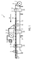
- Fig. 1 shows a schematic view of a thermoforming packaging machine 1 according to the invention.
- the thermoforming packaging machine 1 has a forming station 2, a sealing station 3, a cross-cutting device 4 and a longitudinal cutting device 5, which are arranged in this order in a production direction R on a machine frame 6.
- a feed roller 7 On the input side is located on the machine frame 6, a feed roller 7, from which a film 8 is withdrawn.
- a material reservoir 9 is provided, from which a cover film 10 is drawn off.
- a discharge device 13 in the form of a conveyor belt is provided on the thermoforming packaging machine, with which finished, isolated packages are transported away.
- the thermoforming packaging machine 1 has a feeding device, not shown, which grips the film 8 and transports it further per main working cycle in the production direction R.
- the feed device can be designed, for example, by transport chains 23 arranged on both sides.
- the forming station 2 is formed as a thermoforming station, are formed in the film 8 by deep drawing troughs 14.
- the forming station 2 can be designed such that in the direction perpendicular to the production direction R several troughs are formed side by side.
- the forming station 2 has a hoist 30 to a mold lower part or a tool 22 (see Fig. 2 ) to move upward against a mold top 21 into a working position for the molding process.
- an insertion path 15 is provided in which the troughs 14 formed in the film 8 are filled with products 16.
- the sealing station 3 also has a hoist 30 and a closable chamber 17, in which the atmosphere in the wells 14 can be replaced with a replacement gas or with a gas mixture prior to sealing, for example, by evacuation or gas purging.
- the cross-cutting device 4 also comprises a lifting mechanism 30 and is designed as a punch which cuts through the film 8 and the cover film 10 in a direction transverse to the production direction R between adjacent depressions 14.
- the cross-cutting device 4 operates such that the film 8 is not separated over the entire width, but is not severed at least in an edge region. This allows a controlled onward transport by the feed device.
- the longitudinal cutting device 5 is formed in the illustrated embodiment as a knife assembly, with which the film 8 and the cover sheet 10 between adjacent wells 14 and cut at the lateral edge of the film 8, so that behind the longitudinal cutting device 5 individualized packages are present.
- thermoforming packaging machine 1 also has a controller 18. It has the task to control the processes running in the thermoforming packaging machine 1 processes and monitor.
- a display device 19 with operating elements 20 serves to visualize or influence the process sequences in the packaging machine 1 for or by an operator.
- the film 8 is withdrawn from the feed roller 7 and transported by the feed device in the forming station 2.
- troughs 14 are formed in the film 8 by deep drawing.
- the troughs 14 are transported along with the surrounding area of the film 8 in a main working cycle to the insertion path 15 in which they are filled with products 16.
- the filled wells 14 are transported together with the surrounding area of the film 8 in the main working cycle by the feed device in the sealing station 3.
- the lidding film 10 is transported on to the foil 8 with the advancing movement of the film 8 after a sealing operation.
- the lidding film 10 is withdrawn from the material storage 9.
- the sealing of the lidding film 10 on the troughs 14 produces sealed packages which are separated in the following cuts 4 and 5 and transported out of the deep-drawing packaging machine 1 by means of the discharge device 13.
- Fig. 2 shows a sectional view in the direction of production R of the forming station 2 in the open position.
- the forming station 2 comprises a mold upper part 21 and a lower mold part 22.
- the film 8 is held and transported by a feed device in the form of two laterally provided clamp chains 23.
- In the interior of the lower mold part 22 are provided separately from this two mold inserts 24, which are movable by means of Hubantrieben 25 relative to the lower mold part 22.
- the lifting drives 25 can be designed as pneumatic cylinders 36 or as motor drives, preferably servomotors 36.
- a mold insert 24 itself comprises a mold bottom 26 and a peripheral side wall 27. In this case, the mold insert 24 may be made in one piece or the mold bottom 26 is composed with a plurality of side walls 27 to a unit.
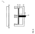
- Fig. 3 shows the forming station 2 in the closed position, by raising the mold lower part 22 in the arrow direction by means of the hoist 30 to the upper die shell 21 is reached.
- the film 8 is clamped between the lower mold part 22 and the upper mold part 21.
- the heated over the mold top 21 film 8 is formed by means of compressed air from above and optionally with additional vacuum in the mold base 22 in the mold inserts 24, ie deep-drawn, each mold insert 24 has an undercut 28 in at least one side wall 27.
- the undercut 28 has a horizontally aligned recess T opposite to an inner peripheral upper edge 29.
- the mold insert 24 has inside a clear height H, the boundary is defined by the top of the mold base 26 and the top edge 29 of the side wall 27.
- the mold inserts 24 become, as in Fig. 4 shown, in the direction of the arrow by means of the lifting actuators 25 away from the mold upper part 21 and relative to the lower mold part 22 and the molded wells 14 moves down.
- the undercuts 28 tensile forces on the film 8, which need not be absorbed by the staple chains 23, but by clamping the film 8 on the outer walls 32 of the mold lower part 22 and the upper mold part 21 and between a web 33 of the mold lower part 22nd and the mold top 21 are received.
- the mold lower part 22 is lowered with the mold inserts 24 contained in its interior down in the arrow direction to release the film 8 for further transport for the next power stroke. Subsequently, the mold inserts 24 can be moved relative to the mold lower part 22 into the mold position as in FIG Fig. 2 be raised, or this relative movement takes place only during or after the closing movement of the mold lower part 22 to the mold upper part 21.
- Fig. 6 shows an alternative embodiment of the mold lower part 22, in which the mold inserts 24 are arranged on a common lifting plate 34 and only a single lifting drive 35 is provided for the relative movement of several or all mold inserts 24 relative to the mold lower part 22.
Description
- Die Erfindung bezieht sich auf eine Tiefziehverpackungsmaschine mit den Merkmalen des Anspruchs 1 und auf ein Verfahren nach Anspruch 8.
- Es ist aus der
EP 2570351 A1 eine Formstation einer Tiefziehverpackungsmaschine bekannt, um Verpackungen mit einem Hinterschnitt formen zu können. Verpackungen mit einem sehr geringen Hinterschnitt werden dort auf Tiefziehverpackungsmaschinen in der Art geformt, dass eine beidseitig vorgesehene Klammerkette zum Folientransport die geformte Folie beim Öffnen des Formwerkzeugunterteils hält. Die beim Öffnen des Formwerkzeugunterteils auftretenden Zugkräfte auf die geformte Folie können von den Klammerketten nur begrenzt aufgenommen werden, da sonst die Folie aus den Klammerketten herausgezogen wird. - Aufgabe der vorliegenden Erfindung ist es, eine verbesserte Formstation für eine Tiefziehverpackungsanlage und ein Verfahren zum Betrieb einer solchen Formstation zur Verfügung zu stellen, um Hinterschnitte in eine Folie zu formen.
- Diese Aufgabe wird gelöst durch eine Tiefziehverpackungsmaschine mit den Merkmalen des Anspruchs 1 bzw. durch ein Verfahren zum Betrieb einer solchen Tiefziehverpackungsmaschine mit den Merkmalen des Anspruchs 8. Vorteilhafte Weiterbildungen der Erfindung sind in den Unteransprüchen angegeben.
- Die erfindungsgemäße Tiefziehverpackungsmaschine umfasst ein Formwerkzeugunterteil und wenigstens einen in dessen Inneren vorgesehenen Formeinsatz und zeichnet sich dadurch aus, dass der Formeinsatz einen Formboden und eine umlaufende Seitenwand aufweist, wobei der Formeinsatz relativ zum den Formeinsatz umgebenden Formwerkzeugunterteil bewegbar ist. Der Formeinsatz weist dabei wenigstens an einer Seitenwand einen Hinterschnitt zum Tiefziehen eines entsprechenden oder kongruenten Hinterschnitts in eine im Formeinsatz zu formende Mulde auf. Auf diese Weise kann beispielsweise eine Standpackung mit einer Form hergestellt werden, wie sie aus der
EP 2 570 351 A1 bekannt ist. - Es können nun ein oder mehrere Formeinsätze von der zu einer Mulde geformten Folie nach dem Abkühlen der Folie selbst nach unten in das Formwerkzeugunterteil entfernt werden, ohne dass die durch Hinterschnitte der Mulden in den Formeinsätzen entstehenden Zugkräfte auf die Folie von seitlichen Klammerketten gehalten werden müssen, da die Folie immer noch zwischen dem Formwerkzeugoberteil und Formwerkzeugunterteil geklemmt sein kann.
- Vorzugsweise ist der Formeinsatz einteilig.
- Das Formwerkzeugunterteil weist bevorzugt einen Hubantrieb für den Formeinsatz auf, um den Formeinsatz relativ zum Formwerkzeugunterteil und damit auch innerhalb des Formwerkzeugunterteils zwischen einer Formposition und einer Entnahmeposition bewegen zu können.
- Vorzugsweise ist ein gemeinsamer Hubantrieb für alle Formeinsätze vorgesehen, um die Bewegung der Formeinsätze zu synchronisieren und die Konstruktion kostengünstig zu gestalten.
- In einer vorteilhaften Ausführung weist der Hubantrieb einen Pneumatikzylinder oder einen Servomotor auf, um beispielsweise schnelle und/oder exakte Positionierungen oder Bewegungen des Formeinsatzes zu ermöglichen.
- Vorzugsweise weist der Formeinsatz im Inneren eine Höhe auf und ist um wenigstens diese Höhe relativ zum Formwerkzeugunterteil bewegbar.
- Dabei weist der Hinterschnitt vorzugsweise eine Tiefe von wenigstens 2 mm auf, relativ zu den nicht-hinterschnittenen Bereichen der Seitenwand.
- Ein erfindungsgemäßes Verfahren zum Formen einer Folie in einer Tiefziehverpackungsmaschine umfasst folgende Schritte:
- Schließen einer Formstation und Klemmen der Folie zwischen einem Formwerkzeugoberteil und einem Formwerkzeugunterteil;
- Tiefziehen der Folie in einen im Inneren des Formwekzeugunterteils aufgenommenen Formeinsatz zum Bilden einer Verpackungsmulde unter gleichzeitigem oder anschließendem Anlegen der Folie an wenigstens einen Hinterschnitt im Formeinsatz, während sich der Formeinsatz in einer Formposition befindet;
- anschließend an das Tiefziehen der Folie: Bewegen des Formeinsatzes relativ zum Formwerkzeugunterteil und zur geformten Folie in eine Entnahmeposition, während die Folie weiterhin zwischen dem Formwerkzeugoberteil und dem Formwerkzeugunterteil geklemmt bleibt;
- anschließend Öffnen der Formstation, um die tiefgezogene Mulde entnehmen oder weitertransportieren zu können.
- Das Verfahren zeichnet sich dadurch aus, dass der Formeinsatz relativ zum Formwerkzeugunterteil und zur geformten Folie in eine Entnahmeposition bewegt wird, während die Folie zwischen dem Formwerkzeugoberteil und dem Formwerkzeugunterteil geklemmt ist.
- Bevorzugt weist der Formeinsatz in seinem Inneren eine lichte Höhe auf und wird um wenigstens diese Höhe relativ zum Werkzeugunterteil bewegt, um den Formeinsatz als Ganzes aus dem Bewegungsbereich der in die Folie geformten Mulde zu bringen und um die Mulde mittels beidseitig vorgesehener Klammerketten nach dem Öffnen der Formstation für einen nächsten Arbeitstakt weitertransportieren zu können.
- In einer besonders vorteilhaften Ausführung werden mehrere Formeinsätze mittels eines gemeinsamen Hubantriebs relativ zum Formwerkzeug zwischen einer Formposition und der Entnahmeposition bewegt.
- Die Folie wird vorzugsweise zwischen wenigstens einem Formplattensteg des Formwerkzeugunterteils und dem Formwerkzeugoberteil geklemmt, um bei mehreren Formeinsätzen bzw. zu formenden Mulden eine Klemmung der Folie um jede Mulde herum aufzuweisen.
- Vorzugsweise wird eine Bewegung des Formeinsatzes in die Formposition bei geschlossener Formstation verhindert, wenn sich zwischen dem Formwerkzeugoberteil und dem Formwerkzeugunterteil eine bereits in die Folie geformte Mulde befindet, um eine Kollision oder ein Zusammenstauchen von geformten Mulden zu verhindern. Dies kann über eine Steuerung der Tiefziehverpackungsmaschine erfolgen, da in der Steuerung die Information vorliegen kann, dass sich bereits geformte Mulden in der geöffneten Formstation bzw. zwischen dem Formwerkzeugunterteil und dem Formwerkzeugoberteil befinden.
- Im Folgenden wird ein vorteilhaftes Ausführungsbeispiel der Erfindung anhand einer Zeichnung näher erläutert. Im Einzelnen zeigen:
- Fig. 1
- eine schematische Seitenansicht einer erfindungsgemäßen Tiefziehverpackungsmaschine,
- Fig. 2
- eine Schnittansicht in Produktionsrichtung der Formstation in offener Stellung,
- Fig. 3
- die Formstation in geschlossener Stellung,
- Fig. 4
- die Formstation mit abgesenkten Formeinsätzen,
- Fig. 5
- die Formstation in offener Stellung und
- Fig. 6
- eine alternative Formstation in offener Stellung.
- Gleiche Komponenten sind in den Figuren durchgängig mit gleichen Bezugszeichen versehen.
-
Fig. 1 zeigt in schematischer Ansicht eine erfindungsgemäße Tiefziehverpackungsmaschine 1. Die Tiefziehverpackungsmaschine 1 weist eine Formstation 2, eine Siegelstation 3, eine Querschneideeinrichtung 4 und eine Längsschneideeinrichtung 5 auf, die in dieser Reihenfolge in einer Produktionsrichtung R an einem Maschinengestell 6 angeordnet sind. Eingangsseitig befindet sich an dem Maschinengestell 6 eine Zufuhrrolle 7, von der eine Folie 8 abgezogen wird. Im Bereich der Siegelstation 3 ist ein Materialspeicher 9 vorgesehen, von dem eine Deckelfolie 10 abgezogen wird. Ausgangsseitig ist an der Tiefziehverpackungsmaschine eine Abfuhreinrichtung 13 in Form eines Transportbandes vorgesehen, mit der fertige, vereinzelte Verpackungen abtransportiert werden. Ferner weist die Tiefziehverpackungsmaschine 1 eine nicht dargestellte Vorschubeinrichtung auf, die die Folie 8 ergreift und diese pro Hauptarbeitstakt in der Produktionsrichtung R weitertransportiert. Die Vorschubeinrichtung kann zum Beispiel durch beidseitig angeordnete Transportketten 23 ausgeführt sein. - In der dargestellten Ausführungsform ist die Formstation 2 als eine Tiefziehstation ausgebildet, bei der in die Folie 8 durch Tiefziehen Mulden 14 geformt werden. Dabei kann die Formstation 2 derart ausgebildet sein, dass in der Richtung senkrecht zur Produktionsrichtung R mehrere Mulden nebeneinander gebildet werden. Die Formstation 2 weist ein Hubwerk 30 auf, um ein Formwerkzeugunterteil bzw. ein Werkzeug 22 (siehe
Fig. 2 ) nach oben gegen ein Formwerkzeugoberteil 21 in eine Arbeitsposition für den Formprozess zu bewegen. In Produktionsrichtung R hinter der Formstation 2 ist eine Einlegestrecke 15 vorgesehen, in der die in der Folie 8 geformten Mulden 14 mit Produkten 16 befüllt werden. - Die Siegelstation 3 verfügt ebenfalls über ein Hubwerk 30 und über eine verschließbare Kammer 17, in der die Atmosphäre in den Mulden 14 vor dem Versiegeln zum Beispiel durch Evakuieren oder Gasspülen mit einem Austauschgas oder mit einem Gasgemisch ersetzt werden kann.
- Die Querschneideeinrichtung 4 umfasst auch ein Hubwerk 30 und ist als Stanze ausgebildet, die die Folie 8 und die Deckelfolie 10 in einer Richtung quer zur Produktionsrichtung R zwischen benachbarten Mulden 14 durchtrennt. Dabei arbeitet die Querschneideeinrichtung 4 derart, dass die Folie 8 nicht über die gesamte Breite aufgetrennt wird, sondern zumindest in einem Randbereich nicht durchtrennt wird. Dies ermöglicht einen kontrollierten Weitertransport durch die Vorschubeinrichtung.
- Die Längsschneideeinrichtung 5 ist in der dargestellten Ausführungsform als eine Messeranordnung ausgebildet, mit der die Folie 8 und die Deckelfolie 10 zwischen benachbarten Mulden 14 und am seitlichen Rand der Folie 8 durchtrennt werden, so dass hinter der Längsschneideeinrichtung 5 vereinzelte Verpackungen vorliegen.
- Die Tiefziehverpackungsmaschine 1 verfügt ferner über eine Steuerung 18. Sie hat die Aufgabe, die in der Tiefziehverpackungsmaschine 1 ablaufenden Prozesse zu steuern und zu überwachen. Eine Anzeigevorrichtung 19 mit Bedienelementen 20 dient zum Visualisieren bzw. Beeinflussen der Prozessabläufe in der Verpackungsmaschine 1 für bzw. durch einen Bediener.
- Die generelle Arbeitsweise der Verpackungsmaschine 1 wird im Folgenden kurz beschrieben.
- Die Folie 8 wird von der Zufuhrrolle 7 abgezogen und durch die Vorschubeinrichtung in die Formstation 2 transportiert. In der Formstation 2 werden durch Tiefziehen Mulden 14 in der Folie 8 gebildet. Die Mulden 14 werden zusammen mit dem umgebenden Bereich der Folie 8 in einem Hauptarbeitstakt zu der Einlegestrecke 15 weitertransportiert, in der sie mit Produkten 16 befüllt werden.
- Anschließend werden die befüllten Mulden 14 zusammen mit dem sie umgebenden Bereich der Folie 8 in dem Hauptarbeitstakt durch die Vorschubeinrichtung in die Siegelstation 3 weitertransportiert. Die Deckelfolie 10 wird nach einem Ansiegelvorgang an die Folie 8 mit der Vorschubbewegung der Folie 8 weitertransportiert. Dabei wird die Deckelfolie 10 von dem Materialspeicher 9 abgezogen. Durch das Ansiegeln der Deckelfolie 10 auf die Mulden 14 entstehen verschlossene Verpackungen, die in den nachfolgenden Schneidungen 4 und 5 vereinzelt und mittels der Abfuhreinrichtung 13 aus der Tiefziehverpackungsmaschine 1 heraus transportiert werden.
-
Fig. 2 zeigt eine Schnittansicht in Produktionsrichtung R der Formstation 2 in offener Stellung. Die Formstation 2 umfasst ein Formwerkzeugoberteil 21 und ein Formwerkzeugunterteil 22. Die Folie 8 wird von einer Vorschubeinrichtung in Form von zwei seitlich vorgesehenen Klammerketten 23 gehalten und transportiert. Im Inneren des Formwerkzeugunterteils 22 sind getrennt von diesem zwei Formeinsätze 24 vorgesehen, die mittels Hubantrieben 25 relativ zum Formwerkzeugunterteil 22 bewegbar sind. Die Hubantriebe 25 können als Pneumatikzylinder 36 oder als motorische Antriebe, vorzugsweise Servomotoren 36, ausgeführt sein. Ein Formeinsatz 24 selbst umfasst einen Formboden 26 und eine umlaufende Seitenwand 27. Dabei kann der Formeinsatz 24 einteilig ausgeführt sein oder der Formboden 26 ist mit mehreren Seitenwänden 27 zu einer Einheit zusammengesetzt. -
Fig. 3 zeigt die Formstation 2 in geschlossener Stellung, die durch das Anheben des Formwerkzeugunterteils 22 in Pfeilrichtung mittels des Hubwerks 30 an das Formwerkzeugoberteil 21 erreicht wird. Dabei wird die Folie 8 zwischen dem Formwerkzeugunterteil 22 und dem Formwerkzeugoberteil 21 geklemmt. In dieser Stellung wird die über das Formwerkzeugoberteil 21 erwärmte Folie 8 mittels Druckluft von oben und optional mit zusätzlichem Vakuum im Formwerkzeugunterteil 22 in die Formeinsätze 24 geformt, d.h. tiefgezogen, wobei jeder Formeinsatz 24 einen Hinterschnitt 28 in wenigstens einer Seitenwand 27 aufweist. Der Hinterschnitt 28 weist eine horizontal ausgerichtete Vertiefung T gegenüber einer inneren umlaufenden Oberkante 29 auf. Der Formeinsatz 24 weist im Inneren auch eine lichte Höhe H auf, deren Begrenzung durch die Oberseite des Formbodens 26 und die Oberkante 29 der Seitenwand 27 definiert ist. - Nach dem Formvorgang werden die Formeinsätze 24, wie in
Fig. 4 dargestellt, in Pfeilrichtung mittels der Hubantriebe 25 vom Formwerkzeugoberteil 21 weg und relativ zum Formwerkzeugunterteil 22 und zu den geformten Mulden 14 nach unten bewegt. Dabei treten durch die Hinterschnitte 28 erzeugte Zugkräfte auf die Folie 8 auf, die nicht durch die Klammerketten 23 aufgenommen werden müssen, sondern durch das Klemmen der Folie 8 an den Außenwänden 32 des Formwerkzeugunterteils 22 und dem Formwerkzeugoberteil 21 sowie zwischen einem Steg 33 des Formwerkzeugunterteils 22 und dem Formwerkzeugoberteil 21 aufgenommen werden. - Nachdem die Mulden 14 aus den Formeinsätzen 24 entfernt wurden, wird, wie in
Fig. 5 gezeigt, das Formwerkzeugunterteil 22 mit den in seinem Inneren enthaltenen Formeinsätzen 24 nach unten in Pfeilrichtung abgesenkt, um die Folie 8 für den Weitertransport für den nächsten Arbeitstakt freizugeben. Anschließend können die Formeinsätze 24 relativ zum Formwerkzeugunterteil 22 in die Formposition wie inFig. 2 angehoben werden, oder diese Relativbewegung findet erst während oder nach der Schließbewegung des Formwerkzeugunterteils 22 an das Formwerkzeugoberteil 21 statt. -
Fig. 6 zeigt eine alternative Ausführung des Formwerkzeugunterteils 22, bei dem die Formeinsätze 24 auf einer gemeinsamen Hubplatte 34 angeordnet sind und lediglich ein einziger Hubantrieb 35 für die Relativbewegung mehrerer oder aller Formeinsätze 24 gegenüber dem Formwerkzeugunterteil 22 vorgesehen ist.
Claims (12)
- Tiefziehverpackungsmaschine (1), umfassend ein Formwerkzeugunterteil (22), in dessen Inneren wenigstens ein Formeinsatz (24) vorgesehen ist, dadurch gekennzeichnet, dass der Formeinsatz (24) einen Formboden (26) und Seitenwände (27) aufweist, wobei der Formeinsatz (24) wenigstens an einer Seitenwand (27) einen Hinterschnitt (28) zum Tiefziehen einer zu formenden Mulde (14) aufweist, und wobei der Formeinsatz (24) relativ zum Formwerkzeugunterteil (22) bewegbar ist.
- Tiefziehverpackungsmaschine nach Anspruch 1, dadurch gekennzeichnet, dass der Formeinsatz (24) einteilig ist.
- Tiefziehverpackungsmaschine nach einem der vorangehenden Ansprüche, dadurch gekennzeichnet, dass das Formwerkzeugunterteil (22) einen Hubantrieb (25, 35) für den Formeinsatz (24) aufweist.
- Tiefziehverpackungsmaschine nach Anspruch 3, dadurch gekennzeichnet, dass ein gemeinsamer Hubantrieb (35) für alle Formeinsätze (24) vorgesehen ist.
- Tiefziehverpackungsmaschine nach Anspruch 3 oder 4, dadurch gekennzeichnet, dass der Hubantrieb (25, 35) einen Pneumatikzylinder (36) oder einen Servomotor (36) aufweist.
- Tiefziehverpackungsmaschine nach einem der vorangehenden Ansprüche, dadurch gekennzeichnet, dass der Formeinsatz (24) im Inneren eine lichte Höhe (H) aufweist und um wenigstens diese Höhe (H) relativ zum Formwerkzeugunterteil (22) bewegbar ist.
- Tiefziehverpackungsmaschine nach einem der vorangehenden Ansprüche, dadurch gekennzeichnet, dass der Hinterschnitt (28) eine Tiefe (T) von wenigstens 2 mm aufweist.
- Verfahren zum Formen einer Folie (8) in einer Tiefziehverpackungsmaschine (1), umfassend:Schließen einer Formstation (2) und Klemmen der Folie (8) zwischen einem Formwerkzeugoberteil (21) und einem Formwerkzeugunterteil (22);Tiefziehen der Folie (8) in einen im Inneren des Formwerkzeugunterteils (22) aufgenommenen Formeinsatz (24) zum Bilden einer Mulde (14) unter Anlegen der Folie (8) an wenigstens einen Hinterschnitt (28) im Formeinsatz (24), während sich der Formeinsatz (24) in einer Formposition befindet,anschließend Bewegen des Formeinsatzes (24) relativ zum Formwerkzeugunterteil (22) und zur geformten Folie (8) in eine Entnahmeposition, während die Folie (8) zwischen dem Formwerkzeugoberteil (21) und dem Formwerkzeugunterteil (22) geklemmt bleibt,anschließend Öffnen der Formstation (2).
- Verfahren nach Anspruch 8, dadurch gekennzeichnet, dass der Formeinsatz (24) im Inneren eine lichte Höhe (H) aufweist und der Formeinsatz (24) um wenigstens diese Höhe (H) relativ zum Formwerkzeugunterteil (22) bewegt wird.
- Verfahren nach Anspruch 8 oder 9, dadurch gekennzeichnet, dass mehrere Formeinsätze (24) mittels eines gemeinsamen Hubantriebs (35) relativ zum Formwerkzeugunterteil (22) zwischen der Formposition und der Entnahmeposition bewegt werden.
- Verfahren nach einem der Ansprüche 8 bis 10, dadurch gekennzeichnet, dass die Folie (8) zwischen wenigstens einem Formplattensteg (33) des Formwerkzeugunterteils (22) und dem Formwerkzeugoberteil (21) geklemmt wird, während der Formeinsatz (24) relativ zum Formwerkzeugunterteil (22) bewegt wird.
- Verfahren nach einem der Ansprüche 8 bis 11, dadurch gekennzeichnet, dass eine Bewegung des Formeinsatzes (24) in die Formposition bei geschlossener Formstation (2) verhindert wird, wenn sich zwischen dem Formwerkzeugoberteil (21) und dem Formwerkzeugunterteil (22) eine bereits in die Folie (8) geformte Mulde (14) befindet.
Priority Applications (3)
| Application Number | Priority Date | Filing Date | Title |
|---|---|---|---|
| ES14180776.8T ES2606363T3 (es) | 2014-08-13 | 2014-08-13 | Máquina de envasado por embutición profunda con inserto de moldeo móvil |
| EP14180776.8A EP2985234B1 (de) | 2014-08-13 | 2014-08-13 | Tiefziehverpackungsmaschine mit bewegbarem Formeinsatz |
| US14/823,953 US10207451B2 (en) | 2014-08-13 | 2015-08-11 | Thermoform packaging machine with movable mold insert |
Applications Claiming Priority (1)
| Application Number | Priority Date | Filing Date | Title |
|---|---|---|---|
| EP14180776.8A EP2985234B1 (de) | 2014-08-13 | 2014-08-13 | Tiefziehverpackungsmaschine mit bewegbarem Formeinsatz |
Publications (2)
| Publication Number | Publication Date |
|---|---|
| EP2985234A1 EP2985234A1 (de) | 2016-02-17 |
| EP2985234B1 true EP2985234B1 (de) | 2016-11-16 |
Family
ID=51352416
Family Applications (1)
| Application Number | Title | Priority Date | Filing Date |
|---|---|---|---|
| EP14180776.8A Active EP2985234B1 (de) | 2014-08-13 | 2014-08-13 | Tiefziehverpackungsmaschine mit bewegbarem Formeinsatz |
Country Status (3)
| Country | Link |
|---|---|
| US (1) | US10207451B2 (de) |
| EP (1) | EP2985234B1 (de) |
| ES (1) | ES2606363T3 (de) |
Cited By (1)
| Publication number | Priority date | Publication date | Assignee | Title |
|---|---|---|---|---|
| DE102019103196A1 (de) * | 2019-02-08 | 2020-08-13 | Buergofol GmbH | Unterwerkzeug für eine Skin-Verpackung |
Families Citing this family (4)
| Publication number | Priority date | Publication date | Assignee | Title |
|---|---|---|---|---|
| US10625892B2 (en) * | 2015-10-14 | 2020-04-21 | Alkar-Rapidpak, Inc. | Web packaging machines with variable depth forming |
| US11072448B1 (en) * | 2017-11-08 | 2021-07-27 | Alistair Thomson | Dynamic loading device |
| JP6684950B1 (ja) * | 2018-06-26 | 2020-04-22 | マルホ発條工業株式会社 | ブリスタ包装機 |
| DE102020204997A1 (de) * | 2020-04-21 | 2021-10-21 | Multivac Sepp Haggenmüller Se & Co. Kg | Tiefziehverpackungsmaschine und Verfahren zum Ansteuern einer Folienstanze |
Family Cites Families (8)
| Publication number | Priority date | Publication date | Assignee | Title |
|---|---|---|---|---|
| DE3446650A1 (de) * | 1984-12-20 | 1986-06-26 | Multivac Sepp Haggenmüller KG, 8941 Wolfertschwenden | Verpackungsmaschine |
| FR2648432B1 (fr) * | 1989-06-16 | 1991-09-13 | Mecaplastic | Dispositif et installation pour le conditionnement de produits quelconques, par exemple de produits alimentaires, dans des barquettes fermees par un film soude de fermeture |
| DE9113290U1 (de) * | 1991-10-25 | 1991-12-19 | Kraemer + Grebe Gmbh & Co Kg Maschinenfabrik, 3560 Biedenkopf, De | |
| DE19824588A1 (de) * | 1998-06-02 | 1999-12-09 | Kraemer & Grebe Kg | Matrize und Verfahren zur Herstellung einer Verpackungsmulde mit Hinterschnitt |
| US6440354B1 (en) * | 1998-12-04 | 2002-08-27 | Kabushiki Kaisha Asano Kenkyusho | Thermoforming process |
| DE102011101053B4 (de) * | 2011-05-10 | 2014-06-05 | Multivac Sepp Haggenmüller Gmbh & Co. Kg | Arbeitsstation für eine Verpackungsmaschine und Verfahren zum Werkzeugwechsel |
| US9126363B2 (en) * | 2011-09-16 | 2015-09-08 | Multivac Sepp Haggenmueller Gmbh & Co. Kg | Thermoforming packaging machine for producing upright standing packages with undercut |
| EP2570351B1 (de) | 2011-09-16 | 2015-03-25 | Multivac Sepp Haggenmüller GmbH & Co. KG | Tiefziehverpackungsmaschine zum Herstellen von Standpackungen mit geformtem Hinterschnitt |
-
2014
- 2014-08-13 ES ES14180776.8T patent/ES2606363T3/es active Active
- 2014-08-13 EP EP14180776.8A patent/EP2985234B1/de active Active
-
2015
- 2015-08-11 US US14/823,953 patent/US10207451B2/en active Active
Cited By (2)
| Publication number | Priority date | Publication date | Assignee | Title |
|---|---|---|---|---|
| DE102019103196A1 (de) * | 2019-02-08 | 2020-08-13 | Buergofol GmbH | Unterwerkzeug für eine Skin-Verpackung |
| US11319097B2 (en) | 2019-02-08 | 2022-05-03 | Buergofol GmbH | Lower tool for vacuum skin packaging |
Also Published As
| Publication number | Publication date |
|---|---|
| ES2606363T3 (es) | 2017-03-23 |
| EP2985234A1 (de) | 2016-02-17 |
| US20160046063A1 (en) | 2016-02-18 |
| US10207451B2 (en) | 2019-02-19 |
Similar Documents
| Publication | Publication Date | Title |
|---|---|---|
| EP2896573B1 (de) | Tiefziehverpackungsmaschine mit Oberfolienformstation und entsprechendes Verfahren | |
| EP2985234B1 (de) | Tiefziehverpackungsmaschine mit bewegbarem Formeinsatz | |
| EP2769923B1 (de) | Tiefziehverpackungsmaschine mit Siegelstation und Verfahren | |
| EP2251264B1 (de) | Verpackungsmaschine und Verfahren zum Verschließen von Behältern mit Deckeln | |
| EP2644516B1 (de) | Verpackungsmaschine mit einer Siegelvorrichtung | |
| EP0710605B1 (de) | Verfahren und Vorrichtung zum Maximieren der Taktgeschwindigkeit einer Vakuumverpackungsmaschine | |
| EP2766262B1 (de) | Tiefziehverpackungsmaschine | |
| EP2259910B1 (de) | Trennvorrichtung | |
| EP2746173B1 (de) | Tiefziehverpackungsmaschine und verfahren | |
| DE102011115142B4 (de) | Verfahren zum Vereinzeln von Verpackungen | |
| DE102011101051A1 (de) | Werkzeugwechseleinrichtung | |
| DE102004023474A1 (de) | Verpackungsmaschine und Verfahren zum Verschließen von Behältern | |
| EP1234765A1 (de) | Schnellwechselvorrichtung an einer Tiefzieh-Verpackungsmaschine | |
| EP2800699B1 (de) | Verpackungsmaschine mit einer schneidstation | |
| EP3109018A1 (de) | Tiefziehverpackungsmaschine mit komplettschnittstation und entsprechendes verfahren | |
| DE102012018974A1 (de) | Tiefziehverpackungsmaschine mit Stempelformung | |
| EP3088315B1 (de) | Tiefziehverpackungsmaschine mit streifenstanze | |
| DE202016000302U1 (de) | Tiefziehverpackungsmaschine | |
| EP2570351B1 (de) | Tiefziehverpackungsmaschine zum Herstellen von Standpackungen mit geformtem Hinterschnitt | |
| EP2537766B1 (de) | Komplettschnittstation und Verfahren zum Vereinzeln von Verpackungen | |
| EP3450134B1 (de) | Formstation für eine tiefziehverpackungsmaschine und verfahren zum wechseln eines formstempels | |
| DE102013101055B4 (de) | Verfahren und Vorrichtung zum Tiefziehen | |
| EP2386492B1 (de) | Verpackungsmaschine und -verfahren mit Drucklufterzeugung | |
| EP2769829B1 (de) | Tiefziehverpackungsmaschine mit Hubeinrichtung, und ein Verfahren | |
| WO2017009179A1 (de) | Verpackungsmaschine mit reststreifenentsorgung |
Legal Events
| Date | Code | Title | Description |
|---|---|---|---|
| PUAI | Public reference made under article 153(3) epc to a published international application that has entered the european phase |
Free format text: ORIGINAL CODE: 0009012 |
|
| AK | Designated contracting states |
Kind code of ref document: A1 Designated state(s): AL AT BE BG CH CY CZ DE DK EE ES FI FR GB GR HR HU IE IS IT LI LT LU LV MC MK MT NL NO PL PT RO RS SE SI SK SM TR |
|
| AX | Request for extension of the european patent |
Extension state: BA ME |
|
| RAP1 | Party data changed (applicant data changed or rights of an application transferred) |
Owner name: MULTIVAC SEPP HAGGENMUELLER SE & CO. KG |
|
| 17P | Request for examination filed |
Effective date: 20160321 |
|
| RBV | Designated contracting states (corrected) |
Designated state(s): AL AT BE BG CH CY CZ DE DK EE ES FI FR GB GR HR HU IE IS IT LI LT LU LV MC MK MT NL NO PL PT RO RS SE SI SK SM TR |
|
| GRAP | Despatch of communication of intention to grant a patent |
Free format text: ORIGINAL CODE: EPIDOSNIGR1 |
|
| RIC1 | Information provided on ipc code assigned before grant |
Ipc: B29C 51/18 20060101ALI20160427BHEP Ipc: B65B 9/04 20060101ALI20160427BHEP Ipc: B29L 31/00 20060101ALI20160427BHEP Ipc: B65B 47/10 20060101AFI20160427BHEP Ipc: B29C 51/26 20060101ALI20160427BHEP |
|
| INTG | Intention to grant announced |
Effective date: 20160601 |
|
| GRAS | Grant fee paid |
Free format text: ORIGINAL CODE: EPIDOSNIGR3 |
|
| GRAA | (expected) grant |
Free format text: ORIGINAL CODE: 0009210 |
|
| AK | Designated contracting states |
Kind code of ref document: B1 Designated state(s): AL AT BE BG CH CY CZ DE DK EE ES FI FR GB GR HR HU IE IS IT LI LT LU LV MC MK MT NL NO PL PT RO RS SE SI SK SM TR |
|
| REG | Reference to a national code |
Ref country code: GB Ref legal event code: FG4D Free format text: NOT ENGLISH |
|
| REG | Reference to a national code |
Ref country code: CH Ref legal event code: NV Representative=s name: BOVARD AG, CH Ref country code: CH Ref legal event code: EP |
|
| REG | Reference to a national code |
Ref country code: IE Ref legal event code: FG4D Free format text: LANGUAGE OF EP DOCUMENT: GERMAN |
|
| REG | Reference to a national code |
Ref country code: AT Ref legal event code: REF Ref document number: 845664 Country of ref document: AT Kind code of ref document: T Effective date: 20161215 |
|
| REG | Reference to a national code |
Ref country code: DE Ref legal event code: R096 Ref document number: 502014001969 Country of ref document: DE |
|
| REG | Reference to a national code |
Ref country code: NL Ref legal event code: FP |
|
| PG25 | Lapsed in a contracting state [announced via postgrant information from national office to epo] |
Ref country code: LV Free format text: LAPSE BECAUSE OF FAILURE TO SUBMIT A TRANSLATION OF THE DESCRIPTION OR TO PAY THE FEE WITHIN THE PRESCRIBED TIME-LIMIT Effective date: 20161116 |
|
| REG | Reference to a national code |
Ref country code: LT Ref legal event code: MG4D |
|
| PG25 | Lapsed in a contracting state [announced via postgrant information from national office to epo] |
Ref country code: GR Free format text: LAPSE BECAUSE OF FAILURE TO SUBMIT A TRANSLATION OF THE DESCRIPTION OR TO PAY THE FEE WITHIN THE PRESCRIBED TIME-LIMIT Effective date: 20170217 Ref country code: NO Free format text: LAPSE BECAUSE OF FAILURE TO SUBMIT A TRANSLATION OF THE DESCRIPTION OR TO PAY THE FEE WITHIN THE PRESCRIBED TIME-LIMIT Effective date: 20170216 Ref country code: LT Free format text: LAPSE BECAUSE OF FAILURE TO SUBMIT A TRANSLATION OF THE DESCRIPTION OR TO PAY THE FEE WITHIN THE PRESCRIBED TIME-LIMIT Effective date: 20161116 Ref country code: SE Free format text: LAPSE BECAUSE OF FAILURE TO SUBMIT A TRANSLATION OF THE DESCRIPTION OR TO PAY THE FEE WITHIN THE PRESCRIBED TIME-LIMIT Effective date: 20161116 |
|
| PG25 | Lapsed in a contracting state [announced via postgrant information from national office to epo] |
Ref country code: FI Free format text: LAPSE BECAUSE OF FAILURE TO SUBMIT A TRANSLATION OF THE DESCRIPTION OR TO PAY THE FEE WITHIN THE PRESCRIBED TIME-LIMIT Effective date: 20161116 Ref country code: PL Free format text: LAPSE BECAUSE OF FAILURE TO SUBMIT A TRANSLATION OF THE DESCRIPTION OR TO PAY THE FEE WITHIN THE PRESCRIBED TIME-LIMIT Effective date: 20161116 Ref country code: HR Free format text: LAPSE BECAUSE OF FAILURE TO SUBMIT A TRANSLATION OF THE DESCRIPTION OR TO PAY THE FEE WITHIN THE PRESCRIBED TIME-LIMIT Effective date: 20161116 Ref country code: PT Free format text: LAPSE BECAUSE OF FAILURE TO SUBMIT A TRANSLATION OF THE DESCRIPTION OR TO PAY THE FEE WITHIN THE PRESCRIBED TIME-LIMIT Effective date: 20170316 Ref country code: RS Free format text: LAPSE BECAUSE OF FAILURE TO SUBMIT A TRANSLATION OF THE DESCRIPTION OR TO PAY THE FEE WITHIN THE PRESCRIBED TIME-LIMIT Effective date: 20161116 |
|
| PG25 | Lapsed in a contracting state [announced via postgrant information from national office to epo] |
Ref country code: EE Free format text: LAPSE BECAUSE OF FAILURE TO SUBMIT A TRANSLATION OF THE DESCRIPTION OR TO PAY THE FEE WITHIN THE PRESCRIBED TIME-LIMIT Effective date: 20161116 Ref country code: DK Free format text: LAPSE BECAUSE OF FAILURE TO SUBMIT A TRANSLATION OF THE DESCRIPTION OR TO PAY THE FEE WITHIN THE PRESCRIBED TIME-LIMIT Effective date: 20161116 Ref country code: RO Free format text: LAPSE BECAUSE OF FAILURE TO SUBMIT A TRANSLATION OF THE DESCRIPTION OR TO PAY THE FEE WITHIN THE PRESCRIBED TIME-LIMIT Effective date: 20161116 Ref country code: SK Free format text: LAPSE BECAUSE OF FAILURE TO SUBMIT A TRANSLATION OF THE DESCRIPTION OR TO PAY THE FEE WITHIN THE PRESCRIBED TIME-LIMIT Effective date: 20161116 Ref country code: CZ Free format text: LAPSE BECAUSE OF FAILURE TO SUBMIT A TRANSLATION OF THE DESCRIPTION OR TO PAY THE FEE WITHIN THE PRESCRIBED TIME-LIMIT Effective date: 20161116 |
|
| REG | Reference to a national code |
Ref country code: DE Ref legal event code: R097 Ref document number: 502014001969 Country of ref document: DE |
|
| REG | Reference to a national code |
Ref country code: FR Ref legal event code: PLFP Year of fee payment: 4 |
|
| PG25 | Lapsed in a contracting state [announced via postgrant information from national office to epo] |
Ref country code: BG Free format text: LAPSE BECAUSE OF FAILURE TO SUBMIT A TRANSLATION OF THE DESCRIPTION OR TO PAY THE FEE WITHIN THE PRESCRIBED TIME-LIMIT Effective date: 20170216 Ref country code: SM Free format text: LAPSE BECAUSE OF FAILURE TO SUBMIT A TRANSLATION OF THE DESCRIPTION OR TO PAY THE FEE WITHIN THE PRESCRIBED TIME-LIMIT Effective date: 20161116 |
|
| PLBE | No opposition filed within time limit |
Free format text: ORIGINAL CODE: 0009261 |
|
| STAA | Information on the status of an ep patent application or granted ep patent |
Free format text: STATUS: NO OPPOSITION FILED WITHIN TIME LIMIT |
|
| 26N | No opposition filed |
Effective date: 20170817 |
|
| PG25 | Lapsed in a contracting state [announced via postgrant information from national office to epo] |
Ref country code: SI Free format text: LAPSE BECAUSE OF FAILURE TO SUBMIT A TRANSLATION OF THE DESCRIPTION OR TO PAY THE FEE WITHIN THE PRESCRIBED TIME-LIMIT Effective date: 20161116 |
|
| PG25 | Lapsed in a contracting state [announced via postgrant information from national office to epo] |
Ref country code: MC Free format text: LAPSE BECAUSE OF FAILURE TO SUBMIT A TRANSLATION OF THE DESCRIPTION OR TO PAY THE FEE WITHIN THE PRESCRIBED TIME-LIMIT Effective date: 20161116 |
|
| REG | Reference to a national code |
Ref country code: IE Ref legal event code: MM4A |
|
| REG | Reference to a national code |
Ref country code: BE Ref legal event code: MM Effective date: 20170831 |
|
| PG25 | Lapsed in a contracting state [announced via postgrant information from national office to epo] |
Ref country code: LU Free format text: LAPSE BECAUSE OF NON-PAYMENT OF DUE FEES Effective date: 20170813 |
|
| PG25 | Lapsed in a contracting state [announced via postgrant information from national office to epo] |
Ref country code: IE Free format text: LAPSE BECAUSE OF NON-PAYMENT OF DUE FEES Effective date: 20170813 |
|
| REG | Reference to a national code |
Ref country code: FR Ref legal event code: PLFP Year of fee payment: 5 |
|
| PG25 | Lapsed in a contracting state [announced via postgrant information from national office to epo] |
Ref country code: BE Free format text: LAPSE BECAUSE OF NON-PAYMENT OF DUE FEES Effective date: 20170831 |
|
| PG25 | Lapsed in a contracting state [announced via postgrant information from national office to epo] |
Ref country code: MT Free format text: LAPSE BECAUSE OF FAILURE TO SUBMIT A TRANSLATION OF THE DESCRIPTION OR TO PAY THE FEE WITHIN THE PRESCRIBED TIME-LIMIT Effective date: 20161116 |
|
| PG25 | Lapsed in a contracting state [announced via postgrant information from national office to epo] |
Ref country code: HU Free format text: LAPSE BECAUSE OF FAILURE TO SUBMIT A TRANSLATION OF THE DESCRIPTION OR TO PAY THE FEE WITHIN THE PRESCRIBED TIME-LIMIT; INVALID AB INITIO Effective date: 20140813 |
|
| PG25 | Lapsed in a contracting state [announced via postgrant information from national office to epo] |
Ref country code: CY Free format text: LAPSE BECAUSE OF FAILURE TO SUBMIT A TRANSLATION OF THE DESCRIPTION OR TO PAY THE FEE WITHIN THE PRESCRIBED TIME-LIMIT Effective date: 20161116 |
|
| PG25 | Lapsed in a contracting state [announced via postgrant information from national office to epo] |
Ref country code: MK Free format text: LAPSE BECAUSE OF FAILURE TO SUBMIT A TRANSLATION OF THE DESCRIPTION OR TO PAY THE FEE WITHIN THE PRESCRIBED TIME-LIMIT Effective date: 20161116 |
|
| PG25 | Lapsed in a contracting state [announced via postgrant information from national office to epo] |
Ref country code: TR Free format text: LAPSE BECAUSE OF FAILURE TO SUBMIT A TRANSLATION OF THE DESCRIPTION OR TO PAY THE FEE WITHIN THE PRESCRIBED TIME-LIMIT Effective date: 20161116 |
|
| PG25 | Lapsed in a contracting state [announced via postgrant information from national office to epo] |
Ref country code: IS Free format text: LAPSE BECAUSE OF FAILURE TO SUBMIT A TRANSLATION OF THE DESCRIPTION OR TO PAY THE FEE WITHIN THE PRESCRIBED TIME-LIMIT Effective date: 20170316 Ref country code: AL Free format text: LAPSE BECAUSE OF FAILURE TO SUBMIT A TRANSLATION OF THE DESCRIPTION OR TO PAY THE FEE WITHIN THE PRESCRIBED TIME-LIMIT Effective date: 20161116 |
|
| REG | Reference to a national code |
Ref country code: AT Ref legal event code: MM01 Ref document number: 845664 Country of ref document: AT Kind code of ref document: T Effective date: 20190813 |
|
| PG25 | Lapsed in a contracting state [announced via postgrant information from national office to epo] |
Ref country code: AT Free format text: LAPSE BECAUSE OF NON-PAYMENT OF DUE FEES Effective date: 20190813 |
|
| P01 | Opt-out of the competence of the unified patent court (upc) registered |
Effective date: 20230801 |
|
| PGFP | Annual fee paid to national office [announced via postgrant information from national office to epo] |
Ref country code: NL Payment date: 20230823 Year of fee payment: 10 |
|
| PGFP | Annual fee paid to national office [announced via postgrant information from national office to epo] |
Ref country code: IT Payment date: 20230831 Year of fee payment: 10 Ref country code: GB Payment date: 20230824 Year of fee payment: 10 Ref country code: ES Payment date: 20230918 Year of fee payment: 10 Ref country code: CH Payment date: 20230902 Year of fee payment: 10 |
|
| PGFP | Annual fee paid to national office [announced via postgrant information from national office to epo] |
Ref country code: FR Payment date: 20230821 Year of fee payment: 10 Ref country code: DE Payment date: 20230822 Year of fee payment: 10 |