EP2800699B1 - Verpackungsmaschine mit einer schneidstation - Google Patents
Verpackungsmaschine mit einer schneidstation Download PDFInfo
- Publication number
- EP2800699B1 EP2800699B1 EP13700034.5A EP13700034A EP2800699B1 EP 2800699 B1 EP2800699 B1 EP 2800699B1 EP 13700034 A EP13700034 A EP 13700034A EP 2800699 B1 EP2800699 B1 EP 2800699B1
- Authority
- EP
- European Patent Office
- Prior art keywords
- cutting
- packaging machine
- packaging
- frame
- machine according
- Prior art date
- Legal status (The legal status is an assumption and is not a legal conclusion. Google has not performed a legal analysis and makes no representation as to the accuracy of the status listed.)
- Active
Links
Images


Classifications
-
- B—PERFORMING OPERATIONS; TRANSPORTING
- B65—CONVEYING; PACKING; STORING; HANDLING THIN OR FILAMENTARY MATERIAL
- B65B—MACHINES, APPARATUS OR DEVICES FOR, OR METHODS OF, PACKAGING ARTICLES OR MATERIALS; UNPACKING
- B65B59/00—Arrangements to enable machines to handle articles of different sizes, to produce packages of different sizes, to vary the contents of packages, to handle different types of packaging material, or to give access for cleaning or maintenance purposes
- B65B59/04—Machines constructed with readily-detachable units or assemblies, e.g. to facilitate maintenance
-
- B—PERFORMING OPERATIONS; TRANSPORTING
- B29—WORKING OF PLASTICS; WORKING OF SUBSTANCES IN A PLASTIC STATE IN GENERAL
- B29C—SHAPING OR JOINING OF PLASTICS; SHAPING OF MATERIAL IN A PLASTIC STATE, NOT OTHERWISE PROVIDED FOR; AFTER-TREATMENT OF THE SHAPED PRODUCTS, e.g. REPAIRING
- B29C51/00—Shaping by thermoforming, i.e. shaping sheets or sheet like preforms after heating, e.g. shaping sheets in matched moulds or by deep-drawing; Apparatus therefor
- B29C51/18—Thermoforming apparatus
- B29C51/20—Thermoforming apparatus having movable moulds or mould parts
- B29C51/22—Thermoforming apparatus having movable moulds or mould parts rotatable about an axis
-
- B—PERFORMING OPERATIONS; TRANSPORTING
- B29—WORKING OF PLASTICS; WORKING OF SUBSTANCES IN A PLASTIC STATE IN GENERAL
- B29C—SHAPING OR JOINING OF PLASTICS; SHAPING OF MATERIAL IN A PLASTIC STATE, NOT OTHERWISE PROVIDED FOR; AFTER-TREATMENT OF THE SHAPED PRODUCTS, e.g. REPAIRING
- B29C51/00—Shaping by thermoforming, i.e. shaping sheets or sheet like preforms after heating, e.g. shaping sheets in matched moulds or by deep-drawing; Apparatus therefor
- B29C51/26—Component parts, details or accessories; Auxiliary operations
- B29C51/264—Auxiliary operations prior to the thermoforming operation, e.g. cutting
-
- B—PERFORMING OPERATIONS; TRANSPORTING
- B65—CONVEYING; PACKING; STORING; HANDLING THIN OR FILAMENTARY MATERIAL
- B65B—MACHINES, APPARATUS OR DEVICES FOR, OR METHODS OF, PACKAGING ARTICLES OR MATERIALS; UNPACKING
- B65B35/00—Supplying, feeding, arranging or orientating articles to be packaged
- B65B35/10—Feeding, e.g. conveying, single articles
- B65B35/28—Feeding, e.g. conveying, single articles by pneumatic conveyors
-
- B—PERFORMING OPERATIONS; TRANSPORTING
- B65—CONVEYING; PACKING; STORING; HANDLING THIN OR FILAMENTARY MATERIAL
- B65B—MACHINES, APPARATUS OR DEVICES FOR, OR METHODS OF, PACKAGING ARTICLES OR MATERIALS; UNPACKING
- B65B39/00—Nozzles, funnels or guides for introducing articles or materials into containers or wrappers
-
- B—PERFORMING OPERATIONS; TRANSPORTING
- B65—CONVEYING; PACKING; STORING; HANDLING THIN OR FILAMENTARY MATERIAL
- B65B—MACHINES, APPARATUS OR DEVICES FOR, OR METHODS OF, PACKAGING ARTICLES OR MATERIALS; UNPACKING
- B65B51/00—Devices for, or methods of, sealing or securing package folds or closures; Devices for gathering or twisting wrappers, or necks of bags
- B65B51/04—Applying separate sealing or securing members, e.g. clips
-
- B—PERFORMING OPERATIONS; TRANSPORTING
- B65—CONVEYING; PACKING; STORING; HANDLING THIN OR FILAMENTARY MATERIAL
- B65B—MACHINES, APPARATUS OR DEVICES FOR, OR METHODS OF, PACKAGING ARTICLES OR MATERIALS; UNPACKING
- B65B61/00—Auxiliary devices, not otherwise provided for, for operating on sheets, blanks, webs, binding material, containers or packages
- B65B61/04—Auxiliary devices, not otherwise provided for, for operating on sheets, blanks, webs, binding material, containers or packages for severing webs, or for separating joined packages
- B65B61/06—Auxiliary devices, not otherwise provided for, for operating on sheets, blanks, webs, binding material, containers or packages for severing webs, or for separating joined packages by cutting
-
- B—PERFORMING OPERATIONS; TRANSPORTING
- B65—CONVEYING; PACKING; STORING; HANDLING THIN OR FILAMENTARY MATERIAL
- B65B—MACHINES, APPARATUS OR DEVICES FOR, OR METHODS OF, PACKAGING ARTICLES OR MATERIALS; UNPACKING
- B65B9/00—Enclosing successive articles, or quantities of material, e.g. liquids or semiliquids, in flat, folded, or tubular webs of flexible sheet material; Subdividing filled flexible tubes to form packages
- B65B9/02—Enclosing successive articles, or quantities of material between opposed webs
- B65B9/04—Enclosing successive articles, or quantities of material between opposed webs one or both webs being formed with pockets for the reception of the articles, or of the quantities of material
-
- B—PERFORMING OPERATIONS; TRANSPORTING
- B65—CONVEYING; PACKING; STORING; HANDLING THIN OR FILAMENTARY MATERIAL
- B65B—MACHINES, APPARATUS OR DEVICES FOR, OR METHODS OF, PACKAGING ARTICLES OR MATERIALS; UNPACKING
- B65B9/00—Enclosing successive articles, or quantities of material, e.g. liquids or semiliquids, in flat, folded, or tubular webs of flexible sheet material; Subdividing filled flexible tubes to form packages
- B65B9/10—Enclosing successive articles, or quantities of material, in preformed tubular webs, or in webs formed into tubes around filling nozzles, e.g. extruded tubular webs
-
- Y—GENERAL TAGGING OF NEW TECHNOLOGICAL DEVELOPMENTS; GENERAL TAGGING OF CROSS-SECTIONAL TECHNOLOGIES SPANNING OVER SEVERAL SECTIONS OF THE IPC; TECHNICAL SUBJECTS COVERED BY FORMER USPC CROSS-REFERENCE ART COLLECTIONS [XRACs] AND DIGESTS
- Y10—TECHNICAL SUBJECTS COVERED BY FORMER USPC
- Y10T—TECHNICAL SUBJECTS COVERED BY FORMER US CLASSIFICATION
- Y10T483/00—Tool changing
- Y10T483/10—Process
Definitions
- the present invention relates to a packaging machine according to the preamble of patent claim 1.
- a generic packaging machine is for example in the DE 31 18 946 A1 described.
- Such packaging machines are well known in the art and are referred to, for example, as so-called form-fill-seal (FFS) packaging machines.
- FFS form-fill-seal
- a packaging tray for example by deep drawing, formed in a sub-film web, then filled with a packaged product and then sealed with a lid film.
- the finished packaging is finally separated by being cut out of at least one film web.
- this is a so-called contour cut, in which the entire contour of the packaging is detached from the film web with a cutting means.
- these packaging machines work in cycles, d. H. the film web / s is / are transported intermittently in each case by a so-called feed length.
- a large number of packages are produced at the same time, which are arranged in a format which consists of several columns and / or several rows. The packages of such a format are always processed simultaneously.
- Packaging machines must be very flexible today, d. H. There must be a variety of different packaging in different formats with them to produce. Since different tools are required for the respective packaging and / or format, they must be changed for the production of different packaging. In order to keep the downtime of the packaging machines according to the invention as low as possible, this tool change must be done as quickly as possible.
- the present invention relates to a packaging machine with a cutting station.
- a packaging machine is, for example, a so-called form-fill-seal packaging machine (FFS packaging machine), in which a packaging tray is formed in a lower film, which is filled with a packaged product and then sealed with a cover film.
- FFS packaging machine form-fill-seal packaging machine
- the thus finished packaging must finally be separated with the cutting station from the lower film and / or the cover film, i. be cut out.
- Such packaging machines work in cycles, d. H. the respective film web is intermittently transported by a so-called feed length along the packaging machine.
- a multiplicity of packages a so-called format consisting of a large number of rows and / or columns, are produced simultaneously. Each of these packages must be separated.
- the cutting station has a cutting means, which is usually provided with a cutting blade and an antidote, which preferably cooperates scissors-like with the cutting means and which usually has a means for clamping the film web before and / or during the cut, on, or a cutting means, which is usually provided with a toothed cutting blade which acts self-tapping and an antidote, which preferably clamps the film web.
- the clamping of the film web before and / or during the cut usually serves at least for enabling and / or improving the cutting action of the cutting means.
- the cutting means and the antidote preferably have the shape of the contour of the package to be cut out of the film web and / or the cutting means moves along a predetermined contour corresponding to the contour of the desired packaging.
- the cutting means and the antidote are at least one, preferably several, drives so long moved toward each other until the respective packaging is cut out to cut out the packaging from the respective film web.
- the drive is preferably provided next to the film web.
- the drive can also be arranged differently or additionally, for example above the film web and / or upstream or downstream of the format to be cut out, provided that the area in which the film web moves along the packaging machine is sufficiently freely accessible and for one Tool change can be used, which can be done much faster than previously possible.
- the cutting means and / or the antidote are each attached to a movable frame.
- This frame-like attachment also allows a very quick and easy tool change.
- the respective tool is preferably at least partially on a horizontal surface of the respective frame. For cutting, the frames are moved relative to each other.
- At least one frame has a free cross-section which corresponds substantially to at least the format to be processed.
- the free cross section of the frame is provided so large that its free cross section corresponds to the circumference of the largest format to be processed on the packaging machine according to the invention.
- Each frame may be interchangeable at the cutting station.
- each frame is at least partially made of profiles, in particular closed profiles, for example rectangular profiles.
- the cutting means and / or the antidote are arranged displaceably on a machine frame, which has a free cross-section which substantially corresponds at least to the format to be processed.
- the free cross section of this frame is provided so large that it corresponds to the circumference of the largest format to be processed on the packaging machine according to the invention.
- the frame may be interchangeable on the packaging machine.
- the frame is at least partially made of profiles, in particular closed profiles, for example rectangular profiles.
- the cutting station has an ejection means which ejects the respectively separated packaging from the respective film web and / or deposits the respective cut-out packaging on a transport means, for example a conveyor belt.
- a transport means for example a conveyor belt.
- one ejection means is provided per package to be cut out.
- this ejection means is arranged on the upper frame.
- each ejection means preferably has a compressed air and / or vacuum connection. This compressed air or vacuum connection particularly preferably takes place via a distributor plate which is connected to at least one compressed air or vacuum source. This can be dispensed with connecting tubes between the source and the respective ejection means.
- This distributor plate has a variety of Recesses, such as holes, which connects the respective source with the respective ejection means.
- valves are provided in these recesses to control or regulate the respective amount of compressed air and / or the negative pressure.
- the ejection means comprises a Venturi nozzle, with which a negative pressure can be generated.
- the ejection means can be reversibly connected to the packaging to be separated in each case in order to set it down after cutting, for example, on a means of transport.
- an elastic seal is provided on the ejection means, which cooperates sealingly with the product to be sucked and / or ejected. More preferably, this seal is a PUR foam, most preferably with closed pores.
- the seal is formed as a closed annular surface, wherein the ring may be a circular ring but need not be
- the seal is formed so that its shape follows the surface to be sucked at least in sections.
- Another preferred subject of the present invention is a packaging machine in which a film web is clamped at least temporarily between two clamping surfaces.
- This clamping may be required, for example, in the region of the forming station in which a packaging tray is formed in the lower film web, in the sealing station in which a lid film is sealed to the lower film web and / or in the cutting station in which the respective packages are separated. to prevent the respective film web from undesirably slipping and / or to clamp the film web and to enable and / or to improve the cutting action of the cutting station.
- a clamping surface is arranged above and a clamping surface below the respective film web, which are moved towards each other for clamping.
- At least one of these clamping surfaces is structured at least in sections, but particularly preferably both of these clamping surfaces are structured at least in sections, in particular these clamping surfaces are provided with a pyramid-like structure.
- the structure of the two clamping surfaces cooperating clamping surfaces is offset, in particular offset so that the tip a pyramid of a clamping surface engages in the intermediate space between at least two pyramids of the other clamping surface.
- Another object of the present invention is a method for changing a cutting tool a cutting station, in which the cutting means and / or the antidote and / or the ejection means is pulled or pushed in or against the direction of the film web in each case from a frame of a cutting station.
- an optional ejection means is placed from above on the upper frame and fixed there.
- the tool change takes place with very simple means, preferably without tools.
- FIG. 1 shows the cutting station 11 of the packaging machine according to the invention.
- This packaging machine preferably has a forming station in which a packaging tray is formed in a so-called lower film web, a filling station in which at least one packaging material is filled into the produced packaging tray of the lower film web and a sealing station in which a lid film is sealed onto the filled packaging tray , Downstream of the sealing station is the cutting station, which separates the finished packaging from the bottom and / or top film web.
- the packaging machine according to the invention operates intermittently, ie at each cycle the respective film web is transported on by a certain feed length along the packaging machine. For processing the respective film web this is preferably quiet.
- each step preferably a plurality of packages, which preferably in a so-called format, which consists of several columns and / or multiple rows, simultaneously produced by the respective processing step for producing the respective packaging is carried out simultaneously.
- the cutting station 11 has a fixed machine frame, which is preferably mounted on the right and left of the machine frame of the packaging machine stationary. At this machine frame, in particular vertically displaceable, a first, here upper frame 3 and / or a second, here lower, frame 8 is provided. For cutting, at least one of the two frames 3, 8 is moved relative to the other frame 3, 8 from a position spaced from the film web to a cutting position.
- At least one frame 3 has a means, for example a spring means, which biases it into its position spaced from the film.
- the other frame 8 is preferably held in its spaced position by gravity.
- the cutting station has at least one, here two, drive means, preferably a cylinder, in particular a high-force cylinder.
- This drive means is, in particular FIG. 3a can be removed, preferably arranged to the right and left of the film web and thus does not block the area below or above the film web, so that this, for example, for a tool change, is available.
- a cutting means 4 is arranged, which has a plurality of cutting, which separates the respective packaging from the respective film web.
- the cutting edge can be a closed stationary blade. This blade usually has a in preferably a plane lying cutting tip, which may also be toothed.
- the cutting edge can also be a so-called contour cutter, which moves for cutting along a predetermined contour.
- an antidote for example a counter knife or a pair of cutting goggles, is arranged, with which the cutting process is enabled and / or improved.
- the antidote interacts with the cutting means during cutting.
- the antidote usually also usually a means for clamping the film web, with which the cutting process allows and / or improved.
- FIG. 2 shows further details of the cutting station according to FIG. 1 and a tool change.
- at least one frame 3, 5, 8, here all frames 3, 5, 8, have a free cross-section 3.1, 5.1, 8.1, which corresponds to at least the respective format to be produced, preferably the maximum manufacturable.
- the cutting means 4 is attached to the upper frame by being pushed by a movement in or against the direction of the film web in the first, here upper machine frame, in particular horizontally, and rests on this and then there, preferably without tools, is fixed.
- both the cutting means 4 and the counter-agent 7 preferably has a plurality of cutting or counter knives.
- the number and arrangement of the cutting / counter knife corresponds to the respective format to be processed, which consists in the present case of two rows and four columns.
- the ejection means 2 must be replaced in a format change. This is preferably, as indicated by the double arrow, in a tool change, here vertically, raised or lowered.
- the tool change with very simple means, preferably without tools, and can be done in a very short time. If necessary, the film web does not have to be severed for a tool change.
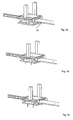
- FIGS. 3a-3c show the cutting out of the respective packaging from the film web 9, wherein in the illustration the film web is moved from right to left through the cutting station.
- FIG. 3a can be removed, are initially both the first frame 3 and the second frame 5 in a spaced-apart from the film web 9 position.
- the first here the upper frame 5 is in this Position held by a spring means.
- a drive means here a cylinder, the second frame 8, as shown by the arrows, here upwards, in its cutting position (see. FIG. 3b ).
- the first frame 3 remains in its position spaced from the film web.
- the drive 1 moves further, in particular, the cylinder retracts further, thereby pulling the first frame 3, as shown by the arrow, down here against the spring force.
- the cutting means 4 provided on the frame 3 is also moved downwards and cooperates with counter means, which are arranged on the first frame 8, so that the respective packages are separated.
- the cut out packages are then removed down through the second frame 8. This can be done by ejecting, for example, blowing out by means of compressed air, which flows from the ejection means 2.
- the packagings can also initially be reversibly connected to the ejection means, for example by negative pressure, and then defined, for example on a means of transport and / or in another packaging means.
- the drive means moves in the opposite direction, ie, for example, a cylinder moves apart again and the first and / or the second frame 3, 8 move into the position spaced from the packaging film. This can then be transported on by another feed length before the next cutting cycle begins.
- FIG. 4 shows the clamping means according to the invention, here the example of the antidote.
- This antidote has a clamping surface 7.1, which is structured at least in sections, here pyramid-like structured, is.
- a structured surface 7.1 is located on the right and left of a recess 7.2, here a circumferential groove around the entire packaging, into which a cutting edge of the cutting means for dicing the respective packaging dips.
- the person skilled in the art recognizes that at least one clamping surface is likewise present on the cutting means, which clamping element cooperates with the clamping surface 7.1.
- This clamping surface is preferably also at least partially structured, in particular pyramid-like structured executed, wherein the pyramids of the respective clamping surfaces are preferably offset from each other provided that the tip of a pyramid of a clamping surface engages in the space between at least two pyramids of the other clamping surface.
- FIG. 5 a possible embodiment of the ejection means 2 is shown.
- This has a housing 14, here a plate, in particular a steel plate, is provided with a pressure and / or Saugffenan gleich.
- a seal 12 is arranged on the housing, which sealing with the product to be sucked or ejected interacts.
- the seal is preferably adapted to the suctioned product, here a sausage.
- the seal is preferably at least partially annular, so that one or more suction and / or pressure chambers 13 form.
- the gasket is made of foamed PUR material that is so elastic that the shape of the gasket in the contact areas adapts to the shape of the product.
Landscapes
- Engineering & Computer Science (AREA)
- Mechanical Engineering (AREA)
- Auxiliary Devices For And Details Of Packaging Control (AREA)
- Containers And Plastic Fillers For Packaging (AREA)
- Basic Packing Technique (AREA)
- Package Closures (AREA)
- Closing Of Containers (AREA)
- Advancing Webs (AREA)
Description
- Die vorliegende Erfindung betrifft eine Verpackungsmaschine gemäß dem Oberbegriff des Patentanspruchs 1.
- Eine gattungsgemäße Verpackungsmaschine ist beispielsweise in der
DE 31 18 946 A1 beschrieben. - Derartige Verpackungsmaschinen sind aus dem Stand der Technik hinlänglich bekannt und werden beispielsweise als sogenannte Form-Fill-Seal- Verpackungsmaschinen (FFS-Verpackungsmaschinen) bezeichnet. Bei diesen Verpackungsmaschinen wird beispielsweise in eine Unterfolienbahn eine Verpackungsmulde, beispielsweise durch Tiefziehen, eingeformt, sodann mit einem Verpackungsgut befüllt und dann mit einer Deckelfolie verschlossen. Die so fertiggestellte Verpackung wird abschließend vereinzelt, indem sie aus mindestens einer Folienbahn ausgeschnitten wird. Vorzugsweise handelt es sich dabei um einen sogenannten Konturschnitt, bei dem mit einem Schneidmittel die gesamte Kontur der Verpackung von der Folienbahn abgelöst wird. Vorzugsweise arbeiten diese Verpackungsmaschinen taktweise, d. h. die Folienbahn/en wird/werden taktweise jeweils um eine sogenannte Vorschublänge weitertransportiert. Dabei wird in der Regel eine Vielzahl von Verpackungen gleichzeitig hergestellt, die in einem Format, das aus mehreren Spalten und/oder mehreren Reihen besteht, angeordnet sind. Die Verpackungen eines derartigen Formates werden immer gleichzeitig bearbeitet.
- Verpackungsmaschinen müssen heutzutage sehr flexibel einsetzbar sein, d. h. es muss eine Vielzahl von unterschiedlichen Verpackungen in unterschiedlichen Formaten mit ihnen herstellbar sein. Da für die jeweilige Verpackung und/oder das jeweilige Format unterschiedliche Werkzeuge benötigt werden, müssen diese für die Herstellung unterschiedlicher Verpackungen gewechselt werden. Um die Stillstandzeiten der erfindungsgemäßen Verpackungsmaschinen möglichst gering zu halten, muss dieser Werkzeugwechsel möglichst schnell erfolgen.
- Es war deshalb die Aufgabe der vorliegenden Erfindung, eine Verpackungsmaschine mit einer Schneidstation zur Verfügung zu stellen, bei der der Werkzeugwechsel schneller als bei Maschinen gemäß dem Stand der Technik erfolgen kann.
- Gelöst wird die Aufgabe mit einer Verpackungsmaschine, welche die Merkmale des Patentanspruchs 1 aufweist.
- Die vorliegende Erfindung betrifft eine Verpackungsmaschine mit einer Schneidstation. Bei einer derartigen Verpackungsmaschine handelt es sich beispielsweise um eine sogenannte Form-Fill-Seal- Verpackungsmaschine (FFS-Verpackungsmaschine), bei der in eine Unterfolie eine Verpackungsmulde eingeformt wird, die mit einem Verpackungsgut befüllt und anschließend mit einer Deckelfolie verschlossen wird. Die so fertiggestellte Verpackung muss abschließend mit der Schneidstation aus der Unterfolie und/oder der Deckelfolie vereinzelt, d.h. ausgeschnitten werden.
- Derartige Verpackungsmaschinen arbeiten taktweise, d. h. die jeweilige Folienbahn wird intermittierend um eine sogenannte Vorschublänge entlang der Verpackungsmaschine transportiert. Dabei werden in der Regel eine Vielzahl von Verpackungen, ein sogenanntes Format, das aus einer Vielzahl von Reihen und/oder Spalten besteht, gleichzeitig hergestellt. Jede dieser Verpackungen muss vereinzelt werden.
- Die Schneidstation weist ein Schneidmittel, das in der Regel mit einer Schneidklinge versehen ist und ein Gegenmittel, das vorzugsweise scherenartig mit dem Schneidmittel zusammenwirkt und das in der Regel ein Mittel aufweist, um die Folienbahn vor und/oder während des Schnitts einzuspannen, auf, oder ein Schneidmittel, das in der Regel mit einer gezahnten Schneidklinge versehen ist, das selbstschneidend wirkt und ein Gegenmittel, das vorzugsweise die Folienbahn einspannt. Das Einspannen der Folienbahn vor und/oder während des Schnitts dient üblicherweise mindestens zum Ermöglichen und/oder Verbessern der Schneidwirkung des Schneidmittels. Das Schneidmittel und das Gegenmittel haben dabei vorzugsweise die Form der Kontur der Verpackung, die aus der Folienbahn ausgeschnitten werden soll und/oder das Schneidmittel bewegt sich entlang einer vorgegebenen Kontur, die der Kontur der gewünschten Verpackung entspricht. Erfindungsgemäß werden zum Ausschneiden der Verpackung aus der jeweiligen Folienbahn das Schneidmittel und das Gegenmittel mit mindestens einem, vorzugsweise mehreren, Antrieben so lange aufeinander zu bewegt, bis die jeweilige Verpackung ausgeschnitten ist. Erfindungsgemäß ist nun vorgesehen, dass der Antrieb vorzugsweise neben der Folienbahn vorgesehen ist. Dadurch ist der Bereich, in dem sich die Folienbahn entlang der Verpackungsmaschine bewegt, frei zugänglich und kann für einen Werkzeugwechsel genutzt werden, so dass dieser wesentlich schneller erfolgen kann als dies bisher möglich war. Der Fachmann versteht, dass der Antrieb auch anders oder zusätzlich, beispielsweise oberhalb der Folienbahn und/oder stromaufwärts bzw. stromabwärts von dem auszuschneidenden Format angeordnet sein kann, sofern der Bereich, in dem sich die Folienbahn entlang der Verpackungsmaschine bewegt, ausreichend frei zugänglich ist und für einen Werkzeugwechsel genutzt werden kann, der wesentlich schneller erfolgen kann, als dies bisher möglich war.
- Gemäß einem bevorzugten Gegenstand der vorliegenden Erfindung ist das Schneidmittel und/oder das Gegenmittel jeweils an einem beweglichen Rahmen befestigt. Diese rahmenartige Befestigung erlaubt ebenfalls einen sehr schnellen und einfachen Werkzeugwechsel. Das jeweilige Werkzeug liegt dabei vorzugsweise zumindest teilweise auf einer horizontalen Fläche des jeweiligen Rahmens auf. Zum Schneiden werden die Rahmen relativ zueinander bewegt.
- Vorzugsweise weist mindestens ein Rahmen einen freien Querschnitt auf, der im Wesentlichen mindestens dem zu bearbeitenden Format entspricht. Vorzugsweise ist der freie Querschnitt des Rahmens so groß vorgesehen, dass sein freier Querschnitt dem Umfang des größten auf der erfindungsgemäßen Verpackungsmaschine zu verarbeitenden Formats entspricht. Jeder Rahmen kann an der Schneidstation austauschbar angeordnet sein. Vorzugsweise ist jeder Rahmen zumindest teilweise aus Profilen, insbesondere geschlossenen Profilen, beispielsweise Rechteckprofilen, hergestellt.
- Weiterhin bevorzugt sind das Schneidmittel und/oder das Gegenmittel verschieblich an einem Maschinenrahmen angeordnet, der einen freien Querschnitt aufweist, der im Wesentlichen mindestens dem zu bearbeitenden Format entspricht. Vorzugsweise ist der freie Querschnitt dieses Rahmens so groß vorgesehen, dass er dem Umfang des größten auf der erfindungsgemäßen Verpackungsmaschine zu verarbeitenden Formats entspricht. Der Rahmen kann an der Verpackungsmaschine austauschbar angeordnet sein. Vorzugsweise ist der Rahmen zumindest teilweise aus Profilen, insbesondere geschlossenen Profilen, beispielsweise Rechteckprofilen, hergestellt.
- Weiterhin weist die Schneidstation ein Ausstoßmittel auf, das die jeweils vereinzelte Verpackung aus der jeweiligen Folienbahn ausstößt und/oder das die jeweils ausgeschnittene Verpackung auf einem Transportmittel, beispielsweise einem Förderband, ablegt. Vorzugsweise ist pro auszuschneidender Verpackung ein Ausstoßmittel vorgesehen. Besonders bevorzugt wird dieses Ausstoßmittel an dem oberen Rahmen angeordnet. Weiterhin bevorzugt weist jedes Ausstoßmittel einen Druckluft- und/oder Vakuumanschluss auf. Besonders bevorzugt erfolgt dieser Druckluft- bzw. Vakuumanschluss jeweils über eine Verteilerplatte, die mit mindestens einer Druckluft- bzw. Vakuumquelle verbunden ist. Dadurch kann auf Verbindungsschläuche zwischen der Quelle und dem jeweiligen Ausstoßmittel verzichtet werden. Diese Verteilerplatte verfügt über eine Vielzahl von Ausnehmungen, beispielsweise Bohrungen, die die jeweilige Quelle mit dem jeweiligen Ausstoßmittel verbindet. Vorzugsweise sind in diesen Ausnehmungen Ventile vorgesehen, um die jeweilige Menge an Druckluft und/oder den Unterdruck zu steuern oder zu regeln.
- Vorzugsweise weist das Ausstoßmittel eine Venturi-Düse auf, mit der ein Unterdruck erzeugt werden kann. Mit diesem Unterdruck kann das Ausstoßmittel reversibel mit der jeweils zu vereinzelnden Verpackung verbunden werden, um diese nach dem Ausschneiden beispielsweise auf einem Transportmittel abzusetzen.
- Vorzugsweise ist an dem Ausstoßmittel eine elastische Dichtung vorgesehen, die dichtend mit dem anzusaugenden und/oder auszustoßenden Produkt zusammenwirkt. Besonders bevorzugt ist diese Dichtung ein PUR-Schaumstoff, ganz besonders bevorzugt mit geschlossenen Poren.
- Vorzugsweise ist die Dichtung als geschlossene ringförmige Fläche ausgebildet, wobei der Ring ein Kreisring sein kann aber nicht sein muss
- Vorzugsweise ist die Dichtung so ausgebildet, dass ihre Form der anzusaugenden Fläche zumindest abschnittsweise folgt.
- Ein weiterer bevorzugter Gegenstand der vorliegenden Erfindung ist eine Verpackungsmaschine, bei der eine Folienbahn zumindest zeitweise zwischen zwei Klemmflächen geklemmt wird. Diese Klemmung kann beispielsweise im Bereich der Formstation, in der eine Verpackungsmulde in die Unterfolienbahn geformt wird, in der Siegelstation, in der eine Deckelfolie an die Unterfolienbahn gesiegelt wird und/oder in der Schneidstation, in der die jeweiligen Verpackungen vereinzelt werden, erforderlich sein, um zu verhindern, dass die jeweilige Folienbahn unerwünschterweise verrutscht und/oder um die Folienbahn einzuspannen und die Schneidwirkung der Schneidstation zu ermöglichen und/oder zu verbessern. Dabei ist eine Klemmfläche oberhalb und eine Klemmfläche unterhalb der jeweiligen Folienbahn angeordnet, die zum Klemmen aufeinander zu bewegt werden. Bevorzugt ist mindestens eine dieser Klemmflächen zumindest abschnittsweise strukturiert, besonders bevorzugt sind jedoch beide dieser Klemmflächen zumindest abschnittsweise strukturiert, insbesondere sind diese Klemmflächen mit einer pyramidenartigen Struktur versehen. Dadurch wird eine besonders gute Klemmwirkung zwischen den Klemmflächen erzielt. Vorzugsweise ist die Struktur der beiden klemmend zusammenwirkenden Klemmflächen versetzt, insbesondere so versetzt, dass die Spitze einer Pyramide einer Klemmfläche in den Zwischenraum zwischen mindestens zwei Pyramiden der anderen Klemmfläche eingreift.
- Ein weiterer Gegenstand der vorliegenden Erfindung ist ein Verfahren zum Wechseln eines Schneidwerkzeuges einer Schneidstation, bei dem das Schneidmittel und/oder das Gegenmittel und/oder das Ausstoßmittel in oder gegen die Laufrichtung der Folienbahn jeweils aus einem Rahmen einer Schneidstation gezogen oder geschoben wird.
- Die zu den erfindungsgemäßen Verpackungsmaschinen gemachten Ausführungen gelten für das erfindungsgemäße Verfahren gleichermaßen und umgekehrt.
- Dadurch, dass das Schneidmittel, das Gegenmittel und/oder das Ausstoßmittel in oder gegen die Laufrichtung der Folienbahn der Folienbahn jeweils aus dem Rahmen einer Schneidstation gezogen werden, ist ein besonders einfacher, platzsparender Werkzeugwechsel möglich.
- Vorzugsweise wird ein gegebenenfalls vorhandenes Ausstoßmittel von oben auf den oberen Rahmen aufgelegt und dort fixiert. Vorzugsweise erfolgt der Werkzeugwechsel mit sehr einfachen Mitteln, vorzugsweise werkzeugfrei.
- Im Folgenden werden die Erfindungen anhand der
Figuren 1 - 5c erläutert. Diese Erläuterungen sind lediglich beispielhaft und schränken den allgemeinen Erfindungsgedanken nicht ein. Die Erläuterungen gelten für alle Gegenstände der vorliegenden Erfindung gleichermaßen. - Figur 1
- zeigt die erfindungsgemäße Schneidstation.
- Figur 2
- zeigt den Werkzeugwechsel bei der erfindungsgemäßen Schneidstation.
- Figuren 3a - 3c
- zeigen das Vereinzeln der Verpackungen aus der Verpackungsfolie.
- Figur 4
- zeigt Details der Klemmflächen.
- Figur 5
- zeigt eine Ausführungsform des Ausstoßmittels
-
Figur 1 zeigt die Schneidstation 11 der erfindungsgemäßen Verpackungsmaschine. Diese Verpackungsmaschine weist vorzugsweise eine Formstation, in der in eine sogenannte Unterfolienbahn eine Verpackungsmulde eingeformt wird, eine Füllstation, in der mindestens ein Verpackungsgut in die hergestellte Verpackungsmulde der Unterfolienbahn eingefüllt wird und eine Siegelstation, in der auf die befüllte Verpackungsmulde eine Deckelfolie gesiegelt wird, auf. Stromabwärts der Siegelstation befindet sich die Schneidstation, die die fertiggestellte Verpackung aus der Unter- und/oder Oberfolienbahn vereinzelt. Die erfindungsgemäße Verpackungsmaschine arbeite taktweise, d. h. bei jedem Takt wird die jeweilige Folienbahn um eine bestimmte Vorschublänge entlang der Verpackungsmaschine weitertransportiert. Zur Bearbeitung der jeweiligen Folienbahn steht diese vorzugsweise still. Bei jedem Arbeitsschritt werden vorzugsweise eine Vielzahl von Verpackungen, die vorzugsweise in einem sogenannten Format, das aus mehreren Spalten und/oder mehreren Reihen besteht, gleichzeitig hergestellt, indem der jeweilige Bearbeitungsschritt zur Herstellung der jeweiligen Verpackung jeweils gleichzeitig erfolgt. Während der jeweiligen Bearbeitung der jeweiligen Folienbahn steht diese vorzugsweise still. Die Schneidstation 11 weist einen ortsfesten Maschinenrahmen auf, der vorzugsweise rechts und links an dem Maschinenrahmen der Verpackungsmaschine ortsfest gelagert ist. An diesem Maschinenrahmen ist, insbesondere vertikal verschieblich, ein erster, hier oberer, Rahmen 3 und/oder ein zweiter, hier unterer, Rahmen 8 vorgesehen. Zum Schneiden wird mindestens einer der beiden Rahmen 3, 8 relativ zu dem anderen Rahmen 3, 8 von einer von der Folienbahn beabstandeten Position in eine Schneidposition bewegt. Vorzugsweise weist mindestens ein Rahmen 3 ein Mittel, beispielsweise ein Federmittel, auf, das ihn in seine von der Folie beabstandete Position vorspannt. Der andere Rahmen 8 wird vorzugsweise durch Schwerkraft in seiner beabstandeten Position gehalten. Zum Bewegen der beiden Rahmen aufeinander zu und/oder voneinander weg weist die Schneidstation mindestens ein, hier zwei, Antriebsmittel, vorzugsweise einen Zylinder, insbesondere einen Hochkraftzylinder, auf. Dieses Antriebsmittel ist, wie insbesondereFigur 3a entnommen werden kann, vorzugsweise rechts und links von der Folienbahn angeordnet und blockiert somit nicht den Bereich unter oder über der Folienbahn, so dass dieser, beispielsweise für einen Werkzeugwechsel, zur Verfügung steht. An dem ersten, hier dem oberen, Rahmen 3 ist ein Schneidmittel 4 angeordnet, das eine Vielzahl von Schneiden aufweist, die die jeweilige Verpackung aus der jeweiligen Folienbahn vereinzelt. Bei der Schneide kann es sich um eine geschlossene, ortsfeste Klinge handeln. Diese Klinge hat in der Regel eine in vorzugsweise einer Ebene liegende Schneidspitze, die jedoch auch gezahnt sein kann. Die Schneide kann aber auch ein sogenannter Konturschneider sein, der sich zum Schneiden entlang einer vorgegebenen Kontur bewegt. An dem zweiten, hier dem unteren, Rahmen ist ein Gegenmittel, beispielsweise ein Gegenmesser oder eine Schneidbrille, angeordnet, mit der der Schneidvorgang ermöglicht und/oder verbessert wird. Das Gegenmittel wirkt beim Schneiden mit dem Schneidmittel zusammen. Das Gegenmittel meist in der Regel auch ein Mittel zum Einspannen der Folienbahn auf, mit dem der Schneidvorgang ermöglichst und/oder verbessert wird. -
Figur 2 zeigt weitere Details der Schneidstation gemäßFigur 1 und einen Werkzeugwechsel. Insbesondere kannFigur 2 entnommen werden, dass mindestens ein Rahmen 3, 5, 8, hier alle Rahmen 3, 5, 8, einen freien Querschnitt 3.1, 5.1, 8.1 aufweisen, der mindestens dem jeweils herzustellenden, vorzugsweise dem maximal herstellbaren, Format entspricht. Das Schneidmittel 4 wird an dem oberen Rahmen befestigt, indem es durch eine Bewegung in oder gegen die Laufrichtung der Folienbahn in den ersten, hier oberen, Maschinenrahmen, insbesondere horizontal, eingeschoben wird und auf diesem aufliegt sowie dann dort, vorzugsweise werkzeugfrei, fixiert wird. Dasselbe gilt für das Gegenmittel, das ebenfalls in oder gegen die Laufrichtung der Folienbahn auf den zweiten, hier unteren, Maschinenrahmen, insbesondere horizontal aufgeschoben und dann dort, vorzugsweise werkzeugfrei, fixiert wird. Der Darstellung gemäßFigur 2 kann entnommen werden, dass sowohl das Schneidmittel 4 als auch das Gegenmittel 7 vorzugsweise eine Vielzahl von Schneiden bzw. Gegenmessern aufweist. Die Anzahl und Anordnung der Schneiden/Gegenmesser entspricht dabei dem jeweils zu verarbeitenden Format, das in dem vorliegenden Fall aus zwei Reihen und vier Spalten besteht. Sofern vorhanden, muss bei einem Formatwechsel in der Regel ebenfalls das Ausstoßmittel 2 ausgetauscht werden. Dieses wird vorzugsweise, wie durch den Doppelpfeil angedeutet, bei einem Werkzeugwechsel, hier vertikal, angehoben bzw. abgesenkt. Der Fachmann erkennt, dass bei der Schneidstation der erfindungsgemäßen Verpackungsmaschine der Werkzeugwechsel mit sehr einfachen Mitteln, vorzugsweise werkzeugfrei, und in sehr kurzer Zeit erfolgen kann. Gegebenenfalls muss für einen Werkzeugwechsel die Folienbahn nicht durchtrennt werden. - Die
Figuren 3a - 3c zeigen das Ausschneiden der jeweiligen Verpackung aus der Folienbahn 9, wobei in der Darstellung die Folienbahn von rechts nach links durch die Schneidstation bewegt wird. WieFigur 3a entnommen werden kann, befinden sich zunächst sowohl der erste Rahmen 3 als auch der zweite Rahmen 5 in einer von der Folienbahn 9 beabstandeten Position. Insbesondere der erste, hier der obere, Rahmen 5 wird in dieser Position durch ein Federmittel gehalten. Sodann bewegt ein Antriebsmittel, hier ein Zylinder, den zweiten Rahmen 8, wie durch die Pfeile dargestellt, hier nach oben, in seine Schneidposition (vgl.Figur 3b ). Der erste Rahmen 3 verbleibt dabei in seiner von der Folienbahn beabstandeten Position. Anschließend bewegt sich der Antrieb 1 weiter, insbesondere fährt der Zylinder weiter ein, und zieht dabei den ersten Rahmen 3, wie durch den Pfeil dargestellt, hier gegen die Federkraft nach unten. Dabei wird ebenfalls das an dem Rahmen 3 vorgesehene Schneidmittel 4 nach unten bewegt und wirkt mit Gegenmitteln, die an dem ersten Rahmen 8 angeordnet sind, jeweils schneidend zusammen, so dass die jeweiligen Verpackungen vereinzelt werden. Die ausgeschnittenen Verpackungen werden dann nach unten durch den zweiten Rahmen 8 hindurch abgeführt. Dies kann durch ein Ausstoßen, beispielweise Ausblasen mittels Druckluft, die von dem Ausstoßmittel 2 ausströmt, erfolgen. Die Verpackungen können aber auch zunächst reversibel mit dem Ausstoßmittel, beispielsweise durch Unterdruck, verbunden und dann definiert, beispielsweise auf einem Transportmittel und/oder in einem weiteren Verpackungsmittel, abgesetzt werden. Anschließend oder gleichzeitig bewegt sich das Antriebsmittel in die entgegengesetzte Richtung, d. h. ein Zylinder fährt beispielsweise wieder auseinander und der erste und/oder der zweite Rahmen 3, 8 bewegen sich in die von der Verpackungsfolie beabstandete Position. Diese kann dann um eine weitere Vorschublänge weiter transportiert werden, bevor der nächste Schneidzyklus beginnt. -
Figur 4 zeigt das erfindungsgemäße Klemmmittel, hier am Beispiel des Gegenmittels. Dieses Gegenmittel weist eine Klemmfläche 7.1 auf, die zumindest abschnittsweise strukturiert, hier pyramidenartig strukturiert, ist. Eine derartige strukturierte Fläche 7.1 befindet sich rechts und links einer Ausnehmung 7.2, hier einer um die gesamte Verpackung umlaufenden Nut, in die eine Schneide des Schneidmittels zum Vereinzeln der jeweiligen Verpackung eintaucht. Der Fachmann erkennt, dass an dem Schneidmittel ebenfalls mindestens eine Klemmfläche vorhanden ist, die klemmend mit der Klemmfläche 7.1 zusammenwirkt. Diese Klemmfläche ist vorzugsweise ebenfalls mindestens abschnittsweise strukturiert, insbesondere pyramidenartig strukturiert, ausgeführt, wobei die Pyramiden der jeweiligen klemmenden Flächen vorzugsweise so versetzt zueinander vorgesehen sind, dass die Spitze einer Pyramiden der einen Klemmfläche in den Zwischenraum zwischen mindestens zwei Pyramiden der anderen Klemmfläche eingreift. - In
Figur 5 ist eine mögliche Ausführungsform des Ausstoßmittels 2 dargestellt. Dieses weist ein Gehäuse 14, hier eine Platte, insbesondere eine Stahlplatte auf, mit einem Druck und/oder Saugmittelanschluss versehen ist. Außerdem ist an dem Gehäuse eine Dichtung 12 angeordnet, die dichtend mit dem anzusaugenden bzw. auszustoßenden Produkt zusammenwirkt. Die Dichtung ist vorzugsweise an das anzusaugende Produkt, hier eine Wurst, angepasst. Die Dichtung ist vorzugsweise zumindest teilweise ringförmig gestaltet, so dass sich eine oder mehrere Saug- und/oder Druckkammern 13 ausbilden. Vorzugsweise ist die Dichtung aus geschäumtem PUR-Material gefertigt, dass so elastisch ist, dass sich die Form der Dichtung in den Kontaktbereichen an die Form des Produkts anpasst. -
- 1
- Antriebsmittel, Hochkraftzylinder
- 2
- Ausstoßmittel
- 3
- erster, oberer Rahmen
- 3.1
- offener Querschnitt des oberen Rahmens
- 4
- Schneidmittel
- 5
- Maschinenrahmen, ortsfester Rahmen
- 5.1
- offener Querschnitt des ortsfesten Rahmens
- 6
- Anschlag
- 7
- Gegenmittel, Gegenmesser, Schneidbrille
- 7.1
- Klemmfläche, strukturierte Fläche
- 7.2
- Ausnehmung, Nut
- 8
- zweiter, unterer Rahmen
- 8.1
- offener Querschnitt des unteren Rahmens
- 9
- Folienbahn
- 10
- Verpackung
- 11
- Schneidstation
- 12
- Dichtung
- 13
- Vakuum- und/oder Druckkammer
- 14
- Gehäuse
- 15
- Saug- und/oder Druckmittelanschluss
Claims (11)
- Verpackungsmaschine, die taktweise arbeitet, mit einer Schneidstation (11), mit der fertiggestellte Verpackungen aus mindestens einer Folienbahn (9) ausgeschnitten werden, indem ein Schneidmittel (4) und ein Gegenmittel (7) und gegebenenfalls ein Ausstoßmittel (2) mit mindestens einem Antrieb (1) aufeinander zu bewegt werden, dadurch gekennzeichnet, dass der Antrieb (1) neben dem auszuschneidenden Format, das aus einer Vielzahl von Reihen und einer Vielzahl von Spalten besteht, vorgesehen ist, so dass ein Wechsel des Schneidmittels und/oder des Ausstoßmittels (2) und/oder des Gegenmittel möglich ist.
- Verpackungsmaschine nach Anspruch 1, dadurch gekennzeichnet, dass das Schneidmittel (4) und/oder das Gegenmittel (7) jeweils an einem beweglichen Rahmen (3, 8) befestigt ist.
- Verpackungsmaschine nach Anspruch 2, dadurch gekennzeichnet, dass mindestens ein Rahmen (3, 5, 8) einen freien Querschnitt (3.1, 5.1, 8.1) aufweist, der im Wesentlichen mindestens dem auszuschneidenden Format entspricht.
- Verpackungsmaschine nach einem der voranstehenden Ansprüche, dadurch gekennzeichnet, dass das Schneidmittel (4) und/oder das Gegenmittel (7) verschieblich an einem Maschinenrahmen angeordnet ist, der einen freien Querschnitt aufweist, der im Wesentlichen mindestens dem auszuschneidenden Format entspricht.
- Verpackungsmaschine nach einem der voranstehenden Ansprüche, dadurch gekennzeichnet, dass die Schneidstation ein Ausstoßmittel (2) aufweist, das vorzugsweise an dem oberen Rahmen angeordnet ist, wobei vorzugsweise pro gleichzeitig auszuschneidende Verpackung jeweils ein Ausstoßmittel (2) vorgesehen ist.
- Verpackungsmaschine nach Anspruch 5, dadurch gekennzeichnet, dass jedes Ausstoßmittel (2) einen Druckluft- und/oder Vakuumanschluss aufweist und dass der jeweils über eine Verteilerplatte mit mindestens einer Druckluft- bzw. Vakuumquelle verbunden ist.
- Verpackungsmaschine nach einem der Ansprüche 5 oder 6, dadurch gekennzeichnet, dass das Ausstoßmittel eine Venturi-Düse als Saugmittel aufweist.
- Verpackungsmaschine nach einem der Ansprüche 5 oder 6 oder 7, dadurch gekennzeichnet, dass an dem Ausstoßmittel (2) eine elastische Dichtung vorgesehen ist, die dichtend mit dem anzusaugenden und/oder auszustoßenden Produkt zusammenwirkt.
- Verpackungsmaschine, nach einem der voranstehenden Ansprüche, bei der eine Folienbahn zumindest zeitweise zwischen zwei Klemmflächen geklemmt wird, dadurch gekennzeichnet, dass mindestens eine Klemmfläche jeweils mindestens abschnittsweise strukturiert ist, insbesondere eine pyramidenartige Struktur aufweist.
- Verpackungsmaschine nach Anspruch 9, dadurch gekennzeichnet, dass die Struktur von zwei klemmend zusammenwirkenden Klemmflächen versetzt zueinander ist.
- Verfahren zum Wechseln eines Schneidwerkzeuges einer Schneidstation, nach einem der voranstehenden Ansprüche, dadurch gekennzeichnet, dass das Schneidmittel (4) und/oder das Gegenmittel (7) und/oder das Ausstoßmittel (2) in oder gegen die Laufrichtung der Folienbahn (9) jeweils aus einem Rahmen (3, 8) gezogen oder geschoben wird.
Priority Applications (2)
| Application Number | Priority Date | Filing Date | Title |
|---|---|---|---|
| PL13700034T PL2800699T3 (pl) | 2012-01-06 | 2013-01-07 | Maszyna pakująca ze stacją tnącą |
| EP15192750.6A EP3009363A1 (de) | 2012-01-06 | 2013-01-07 | Verpackungsmaschine mit einer schneidstation |
Applications Claiming Priority (2)
| Application Number | Priority Date | Filing Date | Title |
|---|---|---|---|
| DE102012000127A DE102012000127A1 (de) | 2012-01-06 | 2012-01-06 | Verpackungsmaschine mit einer Schneidstation |
| PCT/EP2013/050159 WO2013102682A1 (de) | 2012-01-06 | 2013-01-07 | Verpackungsmaschine mit einer schneidstation |
Related Child Applications (2)
| Application Number | Title | Priority Date | Filing Date |
|---|---|---|---|
| EP15192750.6A Division-Into EP3009363A1 (de) | 2012-01-06 | 2013-01-07 | Verpackungsmaschine mit einer schneidstation |
| EP15192750.6A Division EP3009363A1 (de) | 2012-01-06 | 2013-01-07 | Verpackungsmaschine mit einer schneidstation |
Publications (2)
| Publication Number | Publication Date |
|---|---|
| EP2800699A1 EP2800699A1 (de) | 2014-11-12 |
| EP2800699B1 true EP2800699B1 (de) | 2016-01-06 |
Family
ID=47521029
Family Applications (2)
| Application Number | Title | Priority Date | Filing Date |
|---|---|---|---|
| EP13700034.5A Active EP2800699B1 (de) | 2012-01-06 | 2013-01-07 | Verpackungsmaschine mit einer schneidstation |
| EP15192750.6A Withdrawn EP3009363A1 (de) | 2012-01-06 | 2013-01-07 | Verpackungsmaschine mit einer schneidstation |
Family Applications After (1)
| Application Number | Title | Priority Date | Filing Date |
|---|---|---|---|
| EP15192750.6A Withdrawn EP3009363A1 (de) | 2012-01-06 | 2013-01-07 | Verpackungsmaschine mit einer schneidstation |
Country Status (9)
| Country | Link |
|---|---|
| US (1) | US20150217892A1 (de) |
| EP (2) | EP2800699B1 (de) |
| AU (1) | AU2013207173B2 (de) |
| CA (1) | CA2862490A1 (de) |
| DE (1) | DE102012000127A1 (de) |
| DK (1) | DK2800699T3 (de) |
| ES (1) | ES2565073T3 (de) |
| PL (1) | PL2800699T3 (de) |
| WO (1) | WO2013102682A1 (de) |
Families Citing this family (6)
| Publication number | Priority date | Publication date | Assignee | Title |
|---|---|---|---|---|
| EP3088315B2 (de) | 2015-04-30 | 2022-11-02 | MULTIVAC Sepp Haggenmüller SE & Co. KG | Tiefziehverpackungsmaschine mit streifenstanze |
| US20160325868A1 (en) * | 2015-05-08 | 2016-11-10 | Alkar-Rapidpak, Inc. | Contour cutting station for web packaging machine |
| USD807933S1 (en) * | 2015-08-14 | 2018-01-16 | Henri Emil Louis Maurice Zermatten | Tool for a press brake |
| US20180022490A1 (en) * | 2016-07-21 | 2018-01-25 | Ross Industries, Inc. | Vacuum sealing system, apparatus, and method |
| EP4059848B1 (de) | 2021-03-17 | 2024-02-28 | Bizerba SE & Co. KG | Verpackungsmaschine mit integrierter reinigungshilfe |
| CN116062268B (zh) * | 2023-03-06 | 2023-07-11 | 成都圣恩生物科技股份有限公司 | 一种包装袋拆封装置、拆封方法及炒料装置 |
Citations (23)
| Publication number | Priority date | Publication date | Assignee | Title |
|---|---|---|---|---|
| US3685251A (en) | 1970-03-26 | 1972-08-22 | Mahaffy & Harder Eng Co | Automatic packaging apparatus with improved means for cutting and contour trimming of packages |
| DE2336729A1 (de) | 1973-07-19 | 1975-02-06 | Kraemer & Grebe Kg Maschinenun | Verpackungsmaschine |
| DE8103192U1 (de) | 1982-07-29 | Adolf Illig Maschinenbau Gmbh & Co, 7100 Heilbronn | Schneidvorrichtung | |
| DE3118946A1 (de) | 1981-05-13 | 1982-12-16 | Krämer + Grebe GmbH & Co KG Maschinenfabrik, 3560 Biedenkopf | Vorrichtung zum austrennen von muldenfoermig tiefgezogenen, befuellten kunststoff-packungen aus den folienbahnen |
| DE3619811A1 (de) | 1986-06-12 | 1987-12-17 | Kraemer & Grebe Kg | Druckluftantrieb fuer stanz-, schneid- und praegeeinrichtungen |
| DE19820408A1 (de) | 1997-12-17 | 1999-11-11 | Twb Teuto Werkzeugbau Gmbh | Verpackungsmaschine |
| DE19917436A1 (de) | 1999-04-17 | 2000-10-26 | Uhlmann Pac Systeme Gmbh & Co | Vorrichtung zum Übergeben einer Blisterpackung |
| WO2001028865A1 (en) | 1999-10-20 | 2001-04-26 | S.P.C. Limited | Cutting assembly and seal integrity monitoring system for a filling and heat sealing line |
| DE20216772U1 (de) | 2002-10-31 | 2004-03-11 | Trenkle & Schneider Gmbh & Co. Kg | Kombiniertes Stanz- und Schneidwerkzeug |
| DE10347775A1 (de) | 2003-10-15 | 2005-05-19 | Uhlmann Pac-Systeme Gmbh & Co. Kg. | Arbeitsstation |
| DE102005039690A1 (de) | 2005-04-20 | 2006-11-02 | Gerhard Schubert Gmbh | Stanz- und Siegelverfahren |
| DE102005018659A1 (de) | 2005-04-21 | 2006-11-02 | Hamba Filltec Gmbh & Co. Kg | Vorrichtung zum Befüllen von Bechern, Flaschen und anderen Behältern mit Nahrungs-und Genussmitteln |
| EP1849584A2 (de) | 2006-04-27 | 2007-10-31 | UHLMANN PAC-SYSTEME GmbH & Co. KG | Verfahren zur Herstellung von Siegelwerkzeugen sowie eine Siegelstation mit nach diesem Verfahren hergestellten Siegelwerkzeugen |
| EP1849585A2 (de) | 2006-04-28 | 2007-10-31 | UHLMANN PAC-SYSTEME GmbH & Co. KG | Verfahren zur Herstellung von Siegelwerkzeugen unter Berücksichtigung einer Kenngrösse für die Siegelqualität |
| DE202006020352U1 (de) | 2006-07-22 | 2008-04-30 | Krones Ag | Maschine zum Verpacken von Gegenständen |
| EP1851114B1 (de) | 2005-02-10 | 2008-05-21 | Oy M. Haloila Ab | Verfahren und vorrichtung zur bildung einer oberen folienlage aus einer folienbahn |
| EP2033764A1 (de) | 2006-06-27 | 2009-03-11 | IDM World, S.L. | Maschine zum formen, füllen und schliessen von behältern aus expandiertem polymer |
| DE102009036183A1 (de) | 2009-08-05 | 2011-02-17 | Multivac Sepp Haggenmüller Gmbh & Co. Kg | Transportsystem mit Ejektor |
| DE102009060497A1 (de) | 2009-12-23 | 2011-06-30 | Dürr Dental AG, 74321 | Vorrichtung zum Einschließen eines flachen Objektes, insbesondere einer Speicherfolie, in eine Schutzhülle |
| DE102010009536A1 (de) | 2010-02-26 | 2011-09-01 | Cfs Germany Gmbh | Verfahren zum Wechsel des Ober- und Unterwerkzeugs einer Verpackungsmaschine |
| DE102010056319A1 (de) | 2010-12-27 | 2012-06-28 | Multivac Sepp Haggenmüller Gmbh & Co. Kg | Verpackungsmaschine mit einem anhebbaren und absenkbaren Werkzeug |
| EP2522581A1 (de) | 2011-05-10 | 2012-11-14 | MULTIVAC Sepp Haggenmüller GmbH & Co KG | Arbeitsstation für eine Verpackungsmaschine und Verfahren zum Werkzeugwechsel |
| EP2746167A1 (de) | 2012-12-19 | 2014-06-25 | Multivac Sepp Haggenmüller GmbH & Co. KG | Tiefziehverpackungsmaschine mit elektromotorischem Hubwerk |
Family Cites Families (10)
| Publication number | Priority date | Publication date | Assignee | Title |
|---|---|---|---|---|
| US3523474A (en) * | 1968-04-15 | 1970-08-11 | Phillips Petroleum Co | Precision trimming of thermoformed parts |
| BE792884A (fr) * | 1971-12-15 | 1973-03-30 | Filper Corp | Machine et procede de conditionnement de portions independantes |
| US4238950A (en) * | 1979-04-09 | 1980-12-16 | Gulf & Western Manufacturing Company | Bolster arrangement for opposed slide double acting press |
| US4730761A (en) * | 1986-08-15 | 1988-03-15 | Personal Products Company | Cutting flexible formed products from foam retaining sheet |
| US5192484A (en) * | 1988-09-14 | 1993-03-09 | Matsuzawa Co., Ltd. | Method of forming blisters |
| US5225213A (en) * | 1991-12-16 | 1993-07-06 | John Brown Inc. | Apparatus for differential pressure forming and trimming |
| IT237324Y1 (it) * | 1995-12-05 | 2000-09-05 | Sitma Spa | Dispositivo di taglio per il rifilo di confezioni di carta stampatain una macchina confezionatrice |
| ITVR20010132A1 (it) * | 2001-12-11 | 2003-06-11 | Isap Omv Group Spa | Procedimento ed apparecchiatura per il taglio in stampo di oggetti termoformati estraibili dallo stampo senza piastra di prelievo. |
| US20070186740A1 (en) * | 2006-01-20 | 2007-08-16 | Steven Dreyer | Method and apparatus for forming and cutting vinyl tiles with rolled edges |
| DE102007021967A1 (de) * | 2007-05-10 | 2008-11-13 | Gerhard Schubert Gmbh | Verfahren und Vorrichtung zum Siegeln und Entnehmen |
-
2012
- 2012-01-06 DE DE102012000127A patent/DE102012000127A1/de not_active Withdrawn
-
2013
- 2013-01-07 DK DK13700034.5T patent/DK2800699T3/en active
- 2013-01-07 EP EP13700034.5A patent/EP2800699B1/de active Active
- 2013-01-07 ES ES13700034.5T patent/ES2565073T3/es active Active
- 2013-01-07 CA CA2862490A patent/CA2862490A1/en not_active Abandoned
- 2013-01-07 WO PCT/EP2013/050159 patent/WO2013102682A1/de not_active Ceased
- 2013-01-07 EP EP15192750.6A patent/EP3009363A1/de not_active Withdrawn
- 2013-01-07 AU AU2013207173A patent/AU2013207173B2/en not_active Ceased
- 2013-01-07 US US14/368,631 patent/US20150217892A1/en not_active Abandoned
- 2013-01-07 PL PL13700034T patent/PL2800699T3/pl unknown
Patent Citations (23)
| Publication number | Priority date | Publication date | Assignee | Title |
|---|---|---|---|---|
| DE8103192U1 (de) | 1982-07-29 | Adolf Illig Maschinenbau Gmbh & Co, 7100 Heilbronn | Schneidvorrichtung | |
| US3685251A (en) | 1970-03-26 | 1972-08-22 | Mahaffy & Harder Eng Co | Automatic packaging apparatus with improved means for cutting and contour trimming of packages |
| DE2336729A1 (de) | 1973-07-19 | 1975-02-06 | Kraemer & Grebe Kg Maschinenun | Verpackungsmaschine |
| DE3118946A1 (de) | 1981-05-13 | 1982-12-16 | Krämer + Grebe GmbH & Co KG Maschinenfabrik, 3560 Biedenkopf | Vorrichtung zum austrennen von muldenfoermig tiefgezogenen, befuellten kunststoff-packungen aus den folienbahnen |
| DE3619811A1 (de) | 1986-06-12 | 1987-12-17 | Kraemer & Grebe Kg | Druckluftantrieb fuer stanz-, schneid- und praegeeinrichtungen |
| DE19820408A1 (de) | 1997-12-17 | 1999-11-11 | Twb Teuto Werkzeugbau Gmbh | Verpackungsmaschine |
| DE19917436A1 (de) | 1999-04-17 | 2000-10-26 | Uhlmann Pac Systeme Gmbh & Co | Vorrichtung zum Übergeben einer Blisterpackung |
| WO2001028865A1 (en) | 1999-10-20 | 2001-04-26 | S.P.C. Limited | Cutting assembly and seal integrity monitoring system for a filling and heat sealing line |
| DE20216772U1 (de) | 2002-10-31 | 2004-03-11 | Trenkle & Schneider Gmbh & Co. Kg | Kombiniertes Stanz- und Schneidwerkzeug |
| DE10347775A1 (de) | 2003-10-15 | 2005-05-19 | Uhlmann Pac-Systeme Gmbh & Co. Kg. | Arbeitsstation |
| EP1851114B1 (de) | 2005-02-10 | 2008-05-21 | Oy M. Haloila Ab | Verfahren und vorrichtung zur bildung einer oberen folienlage aus einer folienbahn |
| DE102005039690A1 (de) | 2005-04-20 | 2006-11-02 | Gerhard Schubert Gmbh | Stanz- und Siegelverfahren |
| DE102005018659A1 (de) | 2005-04-21 | 2006-11-02 | Hamba Filltec Gmbh & Co. Kg | Vorrichtung zum Befüllen von Bechern, Flaschen und anderen Behältern mit Nahrungs-und Genussmitteln |
| EP1849584A2 (de) | 2006-04-27 | 2007-10-31 | UHLMANN PAC-SYSTEME GmbH & Co. KG | Verfahren zur Herstellung von Siegelwerkzeugen sowie eine Siegelstation mit nach diesem Verfahren hergestellten Siegelwerkzeugen |
| EP1849585A2 (de) | 2006-04-28 | 2007-10-31 | UHLMANN PAC-SYSTEME GmbH & Co. KG | Verfahren zur Herstellung von Siegelwerkzeugen unter Berücksichtigung einer Kenngrösse für die Siegelqualität |
| EP2033764A1 (de) | 2006-06-27 | 2009-03-11 | IDM World, S.L. | Maschine zum formen, füllen und schliessen von behältern aus expandiertem polymer |
| DE202006020352U1 (de) | 2006-07-22 | 2008-04-30 | Krones Ag | Maschine zum Verpacken von Gegenständen |
| DE102009036183A1 (de) | 2009-08-05 | 2011-02-17 | Multivac Sepp Haggenmüller Gmbh & Co. Kg | Transportsystem mit Ejektor |
| DE102009060497A1 (de) | 2009-12-23 | 2011-06-30 | Dürr Dental AG, 74321 | Vorrichtung zum Einschließen eines flachen Objektes, insbesondere einer Speicherfolie, in eine Schutzhülle |
| DE102010009536A1 (de) | 2010-02-26 | 2011-09-01 | Cfs Germany Gmbh | Verfahren zum Wechsel des Ober- und Unterwerkzeugs einer Verpackungsmaschine |
| DE102010056319A1 (de) | 2010-12-27 | 2012-06-28 | Multivac Sepp Haggenmüller Gmbh & Co. Kg | Verpackungsmaschine mit einem anhebbaren und absenkbaren Werkzeug |
| EP2522581A1 (de) | 2011-05-10 | 2012-11-14 | MULTIVAC Sepp Haggenmüller GmbH & Co KG | Arbeitsstation für eine Verpackungsmaschine und Verfahren zum Werkzeugwechsel |
| EP2746167A1 (de) | 2012-12-19 | 2014-06-25 | Multivac Sepp Haggenmüller GmbH & Co. KG | Tiefziehverpackungsmaschine mit elektromotorischem Hubwerk |
Non-Patent Citations (1)
| Title |
|---|
| OFFENKUNDIGE VORBENUTZUNG EINES FORMSCHNEIDERS OS95 DURCH DIE EINSPRECHENDE |
Also Published As
| Publication number | Publication date |
|---|---|
| AU2013207173B2 (en) | 2016-09-22 |
| DK2800699T3 (en) | 2016-04-11 |
| EP3009363A1 (de) | 2016-04-20 |
| PL2800699T3 (pl) | 2016-06-30 |
| AU2013207173A1 (en) | 2014-07-24 |
| ES2565073T3 (es) | 2016-03-31 |
| CA2862490A1 (en) | 2013-07-11 |
| EP2800699A1 (de) | 2014-11-12 |
| US20150217892A1 (en) | 2015-08-06 |
| DE102012000127A1 (de) | 2013-07-11 |
| WO2013102682A1 (de) | 2013-07-11 |
Similar Documents
| Publication | Publication Date | Title |
|---|---|---|
| EP2800699B1 (de) | Verpackungsmaschine mit einer schneidstation | |
| EP2896573B1 (de) | Tiefziehverpackungsmaschine mit Oberfolienformstation und entsprechendes Verfahren | |
| EP2769923B1 (de) | Tiefziehverpackungsmaschine mit Siegelstation und Verfahren | |
| EP2788259B1 (de) | Verpackungsmaschine mit einem kombinierten form- und siegelwerkzeug | |
| DE2829718C2 (de) | Vakuumtiefziehvorrichtung zum Herstellen von napfförmigen Gegenständen durch Saugunterdruck aus einer Bahn aus thermoplastischem Kunststoff | |
| EP2644516B1 (de) | Verpackungsmaschine mit einer Siegelvorrichtung | |
| DE102011115142B4 (de) | Verfahren zum Vereinzeln von Verpackungen | |
| DE10030010A1 (de) | Verfahren zum Herstellen eines Behälters aus einer thermoplastischen Kunststofffolie u. Formwerkzeug zur Durchführung des Verfahrens | |
| WO2013053484A1 (de) | Tiefziehverpackungsmaschine | |
| EP3456641B1 (de) | Tiefziehverpackungsmaschine und verfahren zum formen einer folienbahn in kartonelemente | |
| DE102012018974B4 (de) | Tiefziehverpackungsmaschine mit Stempelformung | |
| WO2014082991A1 (de) | Verpackungsmaschine mit einem werkzeugwechselsystem | |
| EP2985234B1 (de) | Tiefziehverpackungsmaschine mit bewegbarem Formeinsatz | |
| DE202016000302U1 (de) | Tiefziehverpackungsmaschine | |
| EP3539883A1 (de) | Tiefziehverpackungsmaschine mit folienumlenkung | |
| EP3450134B1 (de) | Formstation für eine tiefziehverpackungsmaschine und verfahren zum wechseln eines formstempels | |
| DE2358281A1 (de) | Vorrichtung zur herstellung von beutelblocks aus thermoplastischer kunststoffolie | |
| WO2017009179A1 (de) | Verpackungsmaschine mit reststreifenentsorgung | |
| DE202014101589U1 (de) | Verpackungsmaschine | |
| EP1854615A1 (de) | Formstation mit einer kontinuerlichen durch die Thermoformmaschine durchlaufenden Folie | |
| EP2783990A1 (de) | Schalenverschließmaschine und Verfahren | |
| EP3295800A1 (de) | Sandwichkeksvorrichtung | |
| DE102022118988A1 (de) | Trenneinheit | |
| EP4522389A1 (de) | Trenneinheit | |
| WO2017102541A1 (de) | Verpackungsmaschine und verfahren zur herstellung von vakuumierten verpackungen |
Legal Events
| Date | Code | Title | Description |
|---|---|---|---|
| PUAI | Public reference made under article 153(3) epc to a published international application that has entered the european phase |
Free format text: ORIGINAL CODE: 0009012 |
|
| 17P | Request for examination filed |
Effective date: 20140618 |
|
| AK | Designated contracting states |
Kind code of ref document: A1 Designated state(s): AL AT BE BG CH CY CZ DE DK EE ES FI FR GB GR HR HU IE IS IT LI LT LU LV MC MK MT NL NO PL PT RO RS SE SI SK SM TR |
|
| DAX | Request for extension of the european patent (deleted) | ||
| GRAP | Despatch of communication of intention to grant a patent |
Free format text: ORIGINAL CODE: EPIDOSNIGR1 |
|
| INTG | Intention to grant announced |
Effective date: 20150601 |
|
| GRAP | Despatch of communication of intention to grant a patent |
Free format text: ORIGINAL CODE: EPIDOSNIGR1 |
|
| INTG | Intention to grant announced |
Effective date: 20150703 |
|
| GRAS | Grant fee paid |
Free format text: ORIGINAL CODE: EPIDOSNIGR3 |
|
| GRAA | (expected) grant |
Free format text: ORIGINAL CODE: 0009210 |
|
| AK | Designated contracting states |
Kind code of ref document: B1 Designated state(s): AL AT BE BG CH CY CZ DE DK EE ES FI FR GB GR HR HU IE IS IT LI LT LU LV MC MK MT NL NO PL PT RO RS SE SI SK SM TR |
|
| REG | Reference to a national code |
Ref country code: GB Ref legal event code: FG4D Free format text: NOT ENGLISH |
|
| REG | Reference to a national code |
Ref country code: CH Ref legal event code: EP |
|
| REG | Reference to a national code |
Ref country code: IE Ref legal event code: FG4D Free format text: LANGUAGE OF EP DOCUMENT: GERMAN |
|
| REG | Reference to a national code |
Ref country code: AT Ref legal event code: REF Ref document number: 768622 Country of ref document: AT Kind code of ref document: T Effective date: 20160215 |
|
| REG | Reference to a national code |
Ref country code: DE Ref legal event code: R096 Ref document number: 502013001752 Country of ref document: DE |
|
| REG | Reference to a national code |
Ref country code: FR Ref legal event code: PLFP Year of fee payment: 4 |
|
| REG | Reference to a national code |
Ref country code: ES Ref legal event code: FG2A Ref document number: 2565073 Country of ref document: ES Kind code of ref document: T3 Effective date: 20160331 |
|
| REG | Reference to a national code |
Ref country code: DK Ref legal event code: T3 Effective date: 20160404 |
|
| REG | Reference to a national code |
Ref country code: SE Ref legal event code: TRGR |
|
| REG | Reference to a national code |
Ref country code: NL Ref legal event code: FP |
|
| REG | Reference to a national code |
Ref country code: LT Ref legal event code: MG4D |
|
| REG | Reference to a national code |
Ref country code: NO Ref legal event code: T2 Effective date: 20160106 |
|
| PG25 | Lapsed in a contracting state [announced via postgrant information from national office to epo] |
Ref country code: HR Free format text: LAPSE BECAUSE OF FAILURE TO SUBMIT A TRANSLATION OF THE DESCRIPTION OR TO PAY THE FEE WITHIN THE PRESCRIBED TIME-LIMIT Effective date: 20160106 Ref country code: GR Free format text: LAPSE BECAUSE OF FAILURE TO SUBMIT A TRANSLATION OF THE DESCRIPTION OR TO PAY THE FEE WITHIN THE PRESCRIBED TIME-LIMIT Effective date: 20160407 |
|
| PG25 | Lapsed in a contracting state [announced via postgrant information from national office to epo] |
Ref country code: PT Free format text: LAPSE BECAUSE OF FAILURE TO SUBMIT A TRANSLATION OF THE DESCRIPTION OR TO PAY THE FEE WITHIN THE PRESCRIBED TIME-LIMIT Effective date: 20160506 Ref country code: LV Free format text: LAPSE BECAUSE OF FAILURE TO SUBMIT A TRANSLATION OF THE DESCRIPTION OR TO PAY THE FEE WITHIN THE PRESCRIBED TIME-LIMIT Effective date: 20160106 Ref country code: RS Free format text: LAPSE BECAUSE OF FAILURE TO SUBMIT A TRANSLATION OF THE DESCRIPTION OR TO PAY THE FEE WITHIN THE PRESCRIBED TIME-LIMIT Effective date: 20160106 Ref country code: LT Free format text: LAPSE BECAUSE OF FAILURE TO SUBMIT A TRANSLATION OF THE DESCRIPTION OR TO PAY THE FEE WITHIN THE PRESCRIBED TIME-LIMIT Effective date: 20160106 Ref country code: IS Free format text: LAPSE BECAUSE OF FAILURE TO SUBMIT A TRANSLATION OF THE DESCRIPTION OR TO PAY THE FEE WITHIN THE PRESCRIBED TIME-LIMIT Effective date: 20160506 |
|
| REG | Reference to a national code |
Ref country code: DE Ref legal event code: R026 Ref document number: 502013001752 Country of ref document: DE |
|
| PLBI | Opposition filed |
Free format text: ORIGINAL CODE: 0009260 |
|
| PG25 | Lapsed in a contracting state [announced via postgrant information from national office to epo] |
Ref country code: MC Free format text: LAPSE BECAUSE OF FAILURE TO SUBMIT A TRANSLATION OF THE DESCRIPTION OR TO PAY THE FEE WITHIN THE PRESCRIBED TIME-LIMIT Effective date: 20160106 Ref country code: EE Free format text: LAPSE BECAUSE OF FAILURE TO SUBMIT A TRANSLATION OF THE DESCRIPTION OR TO PAY THE FEE WITHIN THE PRESCRIBED TIME-LIMIT Effective date: 20160106 |
|
| REG | Reference to a national code |
Ref country code: IE Ref legal event code: MM4A |
|
| 26 | Opposition filed |
Opponent name: MULTIVAC SEPP HAGGENMUELLER SE & CO. KG Effective date: 20161005 |
|
| PLAX | Notice of opposition and request to file observation + time limit sent |
Free format text: ORIGINAL CODE: EPIDOSNOBS2 |
|
| PG25 | Lapsed in a contracting state [announced via postgrant information from national office to epo] |
Ref country code: RO Free format text: LAPSE BECAUSE OF FAILURE TO SUBMIT A TRANSLATION OF THE DESCRIPTION OR TO PAY THE FEE WITHIN THE PRESCRIBED TIME-LIMIT Effective date: 20160106 Ref country code: SK Free format text: LAPSE BECAUSE OF FAILURE TO SUBMIT A TRANSLATION OF THE DESCRIPTION OR TO PAY THE FEE WITHIN THE PRESCRIBED TIME-LIMIT Effective date: 20160106 Ref country code: CZ Free format text: LAPSE BECAUSE OF FAILURE TO SUBMIT A TRANSLATION OF THE DESCRIPTION OR TO PAY THE FEE WITHIN THE PRESCRIBED TIME-LIMIT Effective date: 20160106 Ref country code: SM Free format text: LAPSE BECAUSE OF FAILURE TO SUBMIT A TRANSLATION OF THE DESCRIPTION OR TO PAY THE FEE WITHIN THE PRESCRIBED TIME-LIMIT Effective date: 20160106 |
|
| REG | Reference to a national code |
Ref country code: FR Ref legal event code: PLFP Year of fee payment: 5 |
|
| PG25 | Lapsed in a contracting state [announced via postgrant information from national office to epo] |
Ref country code: IE Free format text: LAPSE BECAUSE OF NON-PAYMENT OF DUE FEES Effective date: 20160107 |
|
| PG25 | Lapsed in a contracting state [announced via postgrant information from national office to epo] |
Ref country code: BG Free format text: LAPSE BECAUSE OF FAILURE TO SUBMIT A TRANSLATION OF THE DESCRIPTION OR TO PAY THE FEE WITHIN THE PRESCRIBED TIME-LIMIT Effective date: 20160406 Ref country code: SI Free format text: LAPSE BECAUSE OF FAILURE TO SUBMIT A TRANSLATION OF THE DESCRIPTION OR TO PAY THE FEE WITHIN THE PRESCRIBED TIME-LIMIT Effective date: 20160106 |
|
| PLBB | Reply of patent proprietor to notice(s) of opposition received |
Free format text: ORIGINAL CODE: EPIDOSNOBS3 |
|
| PLAY | Examination report in opposition despatched + time limit |
Free format text: ORIGINAL CODE: EPIDOSNORE2 |
|
| PG25 | Lapsed in a contracting state [announced via postgrant information from national office to epo] |
Ref country code: MT Free format text: LAPSE BECAUSE OF FAILURE TO SUBMIT A TRANSLATION OF THE DESCRIPTION OR TO PAY THE FEE WITHIN THE PRESCRIBED TIME-LIMIT Effective date: 20160106 |
|
| PLBC | Reply to examination report in opposition received |
Free format text: ORIGINAL CODE: EPIDOSNORE3 |
|
| REG | Reference to a national code |
Ref country code: FR Ref legal event code: PLFP Year of fee payment: 6 |
|
| PG25 | Lapsed in a contracting state [announced via postgrant information from national office to epo] |
Ref country code: HU Free format text: LAPSE BECAUSE OF FAILURE TO SUBMIT A TRANSLATION OF THE DESCRIPTION OR TO PAY THE FEE WITHIN THE PRESCRIBED TIME-LIMIT; INVALID AB INITIO Effective date: 20130107 |
|
| PG25 | Lapsed in a contracting state [announced via postgrant information from national office to epo] |
Ref country code: LU Free format text: LAPSE BECAUSE OF NON-PAYMENT OF DUE FEES Effective date: 20160107 Ref country code: CY Free format text: LAPSE BECAUSE OF FAILURE TO SUBMIT A TRANSLATION OF THE DESCRIPTION OR TO PAY THE FEE WITHIN THE PRESCRIBED TIME-LIMIT Effective date: 20160106 Ref country code: MK Free format text: LAPSE BECAUSE OF FAILURE TO SUBMIT A TRANSLATION OF THE DESCRIPTION OR TO PAY THE FEE WITHIN THE PRESCRIBED TIME-LIMIT Effective date: 20160106 |
|
| PG25 | Lapsed in a contracting state [announced via postgrant information from national office to epo] |
Ref country code: AL Free format text: LAPSE BECAUSE OF FAILURE TO SUBMIT A TRANSLATION OF THE DESCRIPTION OR TO PAY THE FEE WITHIN THE PRESCRIBED TIME-LIMIT Effective date: 20160106 Ref country code: TR Free format text: LAPSE BECAUSE OF FAILURE TO SUBMIT A TRANSLATION OF THE DESCRIPTION OR TO PAY THE FEE WITHIN THE PRESCRIBED TIME-LIMIT Effective date: 20160106 |
|
| PLBD | Termination of opposition procedure: decision despatched |
Free format text: ORIGINAL CODE: EPIDOSNOPC1 |
|
| PLBP | Opposition withdrawn |
Free format text: ORIGINAL CODE: 0009264 |
|
| REG | Reference to a national code |
Ref country code: DE Ref legal event code: R100 Ref document number: 502013001752 Country of ref document: DE |
|
| PLBM | Termination of opposition procedure: date of legal effect published |
Free format text: ORIGINAL CODE: 0009276 |
|
| STAA | Information on the status of an ep patent application or granted ep patent |
Free format text: STATUS: OPPOSITION PROCEDURE CLOSED |
|
| 27C | Opposition proceedings terminated |
Effective date: 20191028 |
|
| PGFP | Annual fee paid to national office [announced via postgrant information from national office to epo] |
Ref country code: DK Payment date: 20200123 Year of fee payment: 8 Ref country code: GB Payment date: 20200127 Year of fee payment: 8 Ref country code: NO Payment date: 20200123 Year of fee payment: 8 Ref country code: PL Payment date: 20200102 Year of fee payment: 8 Ref country code: FI Payment date: 20200121 Year of fee payment: 8 Ref country code: SE Payment date: 20200127 Year of fee payment: 8 |
|
| PGFP | Annual fee paid to national office [announced via postgrant information from national office to epo] |
Ref country code: BE Payment date: 20200122 Year of fee payment: 8 |
|
| REG | Reference to a national code |
Ref country code: FI Ref legal event code: MAE |
|
| REG | Reference to a national code |
Ref country code: DK Ref legal event code: EBP Effective date: 20210131 |
|
| REG | Reference to a national code |
Ref country code: NO Ref legal event code: MMEP |
|
| REG | Reference to a national code |
Ref country code: SE Ref legal event code: EUG |
|
| GBPC | Gb: european patent ceased through non-payment of renewal fee |
Effective date: 20210107 |
|
| REG | Reference to a national code |
Ref country code: BE Ref legal event code: MM Effective date: 20210131 |
|
| PG25 | Lapsed in a contracting state [announced via postgrant information from national office to epo] |
Ref country code: FI Free format text: LAPSE BECAUSE OF NON-PAYMENT OF DUE FEES Effective date: 20210107 |
|
| PG25 | Lapsed in a contracting state [announced via postgrant information from national office to epo] |
Ref country code: SE Free format text: LAPSE BECAUSE OF NON-PAYMENT OF DUE FEES Effective date: 20210108 Ref country code: NO Free format text: LAPSE BECAUSE OF NON-PAYMENT OF DUE FEES Effective date: 20210131 Ref country code: GB Free format text: LAPSE BECAUSE OF NON-PAYMENT OF DUE FEES Effective date: 20210107 |
|
| PG25 | Lapsed in a contracting state [announced via postgrant information from national office to epo] |
Ref country code: DK Free format text: LAPSE BECAUSE OF NON-PAYMENT OF DUE FEES Effective date: 20210131 |
|
| PG25 | Lapsed in a contracting state [announced via postgrant information from national office to epo] |
Ref country code: BE Free format text: LAPSE BECAUSE OF NON-PAYMENT OF DUE FEES Effective date: 20210131 |
|
| PG25 | Lapsed in a contracting state [announced via postgrant information from national office to epo] |
Ref country code: PL Free format text: LAPSE BECAUSE OF NON-PAYMENT OF DUE FEES Effective date: 20210107 |
|
| P01 | Opt-out of the competence of the unified patent court (upc) registered |
Effective date: 20230513 |
|
| PGFP | Annual fee paid to national office [announced via postgrant information from national office to epo] |
Ref country code: AT Payment date: 20240118 Year of fee payment: 12 |
|
| PGFP | Annual fee paid to national office [announced via postgrant information from national office to epo] |
Ref country code: DE Payment date: 20250130 Year of fee payment: 13 |
|
| PGFP | Annual fee paid to national office [announced via postgrant information from national office to epo] |
Ref country code: ES Payment date: 20250203 Year of fee payment: 13 |
|
| PGFP | Annual fee paid to national office [announced via postgrant information from national office to epo] |
Ref country code: CH Payment date: 20250201 Year of fee payment: 13 |
|
| PGFP | Annual fee paid to national office [announced via postgrant information from national office to epo] |
Ref country code: FR Payment date: 20250125 Year of fee payment: 13 |
|
| PGFP | Annual fee paid to national office [announced via postgrant information from national office to epo] |
Ref country code: IT Payment date: 20250129 Year of fee payment: 13 |
|
| REG | Reference to a national code |
Ref country code: AT Ref legal event code: MM01 Ref document number: 768622 Country of ref document: AT Kind code of ref document: T Effective date: 20250107 |
|
| PG25 | Lapsed in a contracting state [announced via postgrant information from national office to epo] |
Ref country code: AT Free format text: LAPSE BECAUSE OF NON-PAYMENT OF DUE FEES Effective date: 20250107 |
|
| REG | Reference to a national code |
Ref country code: CH Ref legal event code: U11 Free format text: ST27 STATUS EVENT CODE: U-0-0-U10-U11 (AS PROVIDED BY THE NATIONAL OFFICE) Effective date: 20260201 |
|
| PGFP | Annual fee paid to national office [announced via postgrant information from national office to epo] |
Ref country code: NL Payment date: 20260123 Year of fee payment: 14 |