EP3829276B1 - Gleitschienenmechanismus - Google Patents
Gleitschienenmechanismus Download PDFInfo
- Publication number
- EP3829276B1 EP3829276B1 EP21151345.2A EP21151345A EP3829276B1 EP 3829276 B1 EP3829276 B1 EP 3829276B1 EP 21151345 A EP21151345 A EP 21151345A EP 3829276 B1 EP3829276 B1 EP 3829276B1
- Authority
- EP
- European Patent Office
- Prior art keywords
- bracket
- rail
- section
- supporting
- wall
- Prior art date
- Legal status (The legal status is an assumption and is not a legal conclusion. Google has not performed a legal analysis and makes no representation as to the accuracy of the status listed.)
- Active
Links
Images


Classifications
-
- A—HUMAN NECESSITIES
- A47—FURNITURE; DOMESTIC ARTICLES OR APPLIANCES; COFFEE MILLS; SPICE MILLS; SUCTION CLEANERS IN GENERAL
- A47B—TABLES; DESKS; OFFICE FURNITURE; CABINETS; DRAWERS; GENERAL DETAILS OF FURNITURE
- A47B88/00—Drawers for tables, cabinets or like furniture; Guides for drawers
- A47B88/40—Sliding drawers; Slides or guides therefor
- A47B88/407—Adjustably or detachably mounted drawers
-
- F—MECHANICAL ENGINEERING; LIGHTING; HEATING; WEAPONS; BLASTING
- F16—ENGINEERING ELEMENTS AND UNITS; GENERAL MEASURES FOR PRODUCING AND MAINTAINING EFFECTIVE FUNCTIONING OF MACHINES OR INSTALLATIONS; THERMAL INSULATION IN GENERAL
- F16C—SHAFTS; FLEXIBLE SHAFTS; ELEMENTS OR CRANKSHAFT MECHANISMS; ROTARY BODIES OTHER THAN GEARING ELEMENTS; BEARINGS
- F16C29/00—Bearings for parts moving only linearly
- F16C29/02—Sliding-contact bearings
-
- A—HUMAN NECESSITIES
- A47—FURNITURE; DOMESTIC ARTICLES OR APPLIANCES; COFFEE MILLS; SPICE MILLS; SUCTION CLEANERS IN GENERAL
- A47B—TABLES; DESKS; OFFICE FURNITURE; CABINETS; DRAWERS; GENERAL DETAILS OF FURNITURE
- A47B88/00—Drawers for tables, cabinets or like furniture; Guides for drawers
- A47B88/40—Sliding drawers; Slides or guides therefor
- A47B88/423—Fastening devices for slides or guides
- A47B88/427—Fastening devices for slides or guides at drawer side
-
- A—HUMAN NECESSITIES
- A47—FURNITURE; DOMESTIC ARTICLES OR APPLIANCES; COFFEE MILLS; SPICE MILLS; SUCTION CLEANERS IN GENERAL
- A47B—TABLES; DESKS; OFFICE FURNITURE; CABINETS; DRAWERS; GENERAL DETAILS OF FURNITURE
- A47B88/00—Drawers for tables, cabinets or like furniture; Guides for drawers
- A47B88/40—Sliding drawers; Slides or guides therefor
- A47B88/423—Fastening devices for slides or guides
- A47B88/43—Fastening devices for slides or guides at cabinet side
-
- A—HUMAN NECESSITIES
- A47—FURNITURE; DOMESTIC ARTICLES OR APPLIANCES; COFFEE MILLS; SPICE MILLS; SUCTION CLEANERS IN GENERAL
- A47B—TABLES; DESKS; OFFICE FURNITURE; CABINETS; DRAWERS; GENERAL DETAILS OF FURNITURE
- A47B88/00—Drawers for tables, cabinets or like furniture; Guides for drawers
- A47B88/40—Sliding drawers; Slides or guides therefor
- A47B88/49—Sliding drawers; Slides or guides therefor with double extensible guides or parts
-
- H—ELECTRICITY
- H05—ELECTRIC TECHNIQUES NOT OTHERWISE PROVIDED FOR
- H05K—PRINTED CIRCUITS; CASINGS OR CONSTRUCTIONAL DETAILS OF ELECTRIC APPARATUS; MANUFACTURE OF ASSEMBLAGES OF ELECTRICAL COMPONENTS
- H05K7/00—Constructional details common to different types of electric apparatus
- H05K7/14—Mounting supporting structure in casing or on frame or rack
- H05K7/1485—Servers; Data center rooms, e.g. 19-inch computer racks
- H05K7/1488—Cabinets therefor, e.g. chassis or racks or mechanical interfaces between blades and support structures
- H05K7/1489—Cabinets therefor, e.g. chassis or racks or mechanical interfaces between blades and support structures characterized by the mounting of blades therein, e.g. brackets, rails, trays
Definitions
- the present invention is related to a slide rail mechanism with a bracket.
- US patent number 6,230,903 B1 discloses a rack system. Wherein, a first mounting bracket and a second mounting bracket are slidably attached on a first end and a second end of a rail member (an outer rail) respectively.
- US patent number 8, 028, 965 B2 discloses an adjustable bracket of a slide rail assembly. Wherein, a fix base is fixedly arranged on an outer rail, and a bracket is slidably mounted in a passage of the fix base.
- US patent number 9, 328, 769 B1 discloses a bracket device of a slide rail assembly including a rail member (an outer rail), a first supporting frame, a second supporting frame, a third supporting frame and a mounting bracket.
- the first supporting frame is fixedly arranged on the rail member.
- the second supporting frame, the third supporting frame and the mounting bracket are movable, stretchable and retractable relative to the first supporting frame.
- the mounting bracket can be adjusted to be located at a first position relative to the rail member according to user's requirement (as shown in FIG. 5 of the US patent), or be located at a second position (as shown in FIG. 7 of the US patent).
- the mounting bracket when the mounting bracket is located at the first position relative to the rail member, the mounting bracket is able to partially clad the rail member and the first supporting frame. However, when the mounting bracket is located at the second position relative to the rail member, the mounting bracket does not clad any part of the first supporting frame (although the mounting bracket partially clads the rail member).
- China patent number 104507297 B discloses a slide rail frame including a front frame and a rear frame.
- the front frame is fixedly mounted on a rail member (an outer rail).
- the rear frame is movably arranged in a sliding slot of the front frame.
- China patent number 205378453 U discloses a reinforced rear frame structure of a slide rail.
- the reinforced rear frame structure includes a rail member, a fixing frame and a sliding frame.
- the fixing frame is fixedly mounted on a rear portion of the rail member, and the fixing frame is embedded in the sliding frame.
- China patent number 205356912 U discloses a slide rail frame including a rail member, a front frame and a rear frame.
- the front frame is fixedly arranged on the rail member, and the front frame penetrates into a passage of the rear frame.
- Taiwan patent number 1481364 B discloses a slide rail assembly including a front bracket, a first and a second rear brackets, and a reinforcement member.
- the front bracket is mounted on a front end of an outer rail of the assembly.
- the first rear bracket is mounted on an outside of the outer rail.
- the second rear bracket is movably mounted on the first rear bracket.
- the reinforcement member includes a body, a pair of a first support portions, and a pair of a second support portions.
- the body includes a groove and a contact portion. The contact portion extends into the groove and contacts with the outer rail.
- the pairs of the first support portions extend to movably hold the outer rail.
- the pairs of the second support portions extend to movably hold the second rear bracket.
- the slide rail assembly may mount on a rack via the front and second rear brackets.
- the reinforcement member is movable relative to the outer rail and the second rear bracket for supporting the strength of the outer rail and the second rear bracket.
- China patent number 106604596 A discloses a slide rail assembly and a bracket device thereof.
- the bracket device used for a rail member is adapted for being mounted on a rack.
- the bracket device includes a main support member, a first support member, a second support member and a bracket.
- the main support member is connected with the rail member.
- the first support member is movable related to the main support member.
- the second support member is movable related to the first support member.
- the bracket is arranged on the second support member, and the bracket can be mounted on the rack.
- the present invention aims at providing a slide rail mechanism having a bracket.
- the claimed slide rail mechanism includes a rail member, a first bracket and a reinforcing member.
- the first bracket is movable relative to the rail member.
- the reinforcing member is arranged between the rail member and the first bracket.
- the first bracket, the rail member and the reinforcing member support each other when the first bracket is moved and adjusted to an arbitrary position.
- the rail member includes a first rail portion, a second rail portion and a longitudinal body connected between the first rail portion and the second rail portion.
- the first bracket includes a first supporting portion, a second supporting portion and a longitudinal supporting portion connected between the first supporting portion and the second supporting portion.
- the reinforcing member includes a first wall portion, a second wall portion and a longitudinal wall connected between the first wall portion and the second wall portion.
- the first wall portion of the reinforcing member includes a first wall section and a second wall section bent relative to the first wall section.
- the second wall portion of the reinforcing member includes a third wall section and a fourth wall section bent relative to the third wall section.
- the first supporting portion of the first bracket further includes a first bending section.
- the first bending section and a lateral side of the first rail portion of the rail member are able to support each other.
- the second supporting portion of the first bracket further includes a second bending section.
- the second bending section and a lateral side of the second rail portion of the rail member are able to support each other.
- the rail member has a first side and a second side.
- the reinforcing member is connected to the first side.
- the slide rail mechanism further includes at least one moving rail movably mounted on the second side.
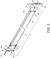
- a slide rail mechanism according to a first example includes a rail member 22, a first bracket 24 and a reinforcing member 26.
- the slide rail mechanism further includes a second bracket 28.
- the rail member 22 includes a first rail portion 30a, a second rail portion 30b and a longitudinal body 32 connected between the first rail portion 30a and the second rail portion 30b.
- the first rail portion 30a and the second rail portion 30b are laterally extended from the longitudinal body 32.
- the first bracket 24 is movably arranged on one of the rail member 22 and the reinforcing member 26.
- the first bracket 24 is movably arranged on the rail member 22.
- the first bracket 24 is movably arranged on the reinforcing member 26, or the first bracket 24 is movably arranged on the rail member 22 and the reinforcing member 26.
- the first bracket 24 is movable and a position of the first bracket 24 relative to the rail member 22 can be adjusted.
- the first bracket 24 is arranged adjacent to a first end portion E1 of the rail member 22.
- the first bracket 24 includes a first supporting portion 34a, a second supporting portion 34b and a longitudinal supporting portion 36 connected between the first supporting portion 34a and the second supporting portion 34b.
- the first bracket 24 includes at least one first mounting portion 38.
- the first bracket 24 includes an end wall 40 bent relative to the longitudinal supporting portion 36.
- the end wall 40 is substantially bent vertically relative to the longitudinal supporting portion 36, but the present invention is not limited thereto.
- the at least one first mounting portion 38 is arranged on the end wall 40. It is noticed that there are two first mounting portions 38 according to the example in FIG. 2 , but the present example is not limited thereto.
- the first bracket 24 can include just one first mounting portion 38. The number of the first mounting portion 38 depends on specific requirements.
- the reinforcing member 26 is arranged between the rail member 22 and the first bracket 24. Furthermore, the reinforcing member 26 is connected to the rail member 22 and can be regarded as a part of the rail member 22. Preferably, the reinforcing member 26 is fixedly arranged on the longitudinal body 32 of the rail member 22.
- the second bracket 28 is arranged on one of the rail member 22 and the reinforcing member 26.
- the second bracket 28 is able to be arranged on the rail member 22.
- the reinforcing member 26 can be regarded as a part of the rail member 22, the location of the reinforcing member 26 can be extended to the second bracket 28 specifically, such that the second bracket 28 is able to be arranged on the reinforcing member 26, but the present example is not limited thereto.
- the second bracket 28 is arranged adjacent to a second end portion E2 of the rail member 22, and is arranged far from the first end portion E1.
- the second bracket 28 is fixedly arranged adjacent to the second end portion E2 of the rail member 22.
- the second bracket 28 includes at least one second mounting portion 42.
- the at least one second mounting portion 42 is arranged corresponding to the at least one first mounting portion 38.
- the second bracket 28 includes a longitudinal supporting wall 44 and an end plate 46 bent relative to the longitudinal supporting wall 44.
- the end plate 46 is substantially bent vertically relative to the longitudinal supporting wall 44, but the present example is not limited thereto.
- the at least one second mounting portion 42 is arranged on the end plate 46.
- there are two second mounting portions 42 according to the example in FIG. 2 but the present example is not limited thereto.
- the second bracket 28 can include just one second mounting portion 42. The number of the second mounting portion 42 depends on specific requirements.
- the at least one first mounting portion 38 of the first bracket 24 is configured to mount the rail member 22 to a first post 48a of a rack.
- the at least one second mounting portion 42 of the second bracket 28 is configured to mount the rail member 22 to a second post 48b of the rack.
- the first bracket 24 is able to be moved to a first position P1 relative to the rail member 22, such that a first distance is formed between the first bracket 24 and the second bracket 28, in order to correspond to a first gap L1 between the first post 48a and the second post 48b.
- the first bracket 24 is movable along a length direction (a longitudinal direction) of the rail member 22 and the reinforcing member 26.
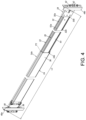
- the first bracket 24 is able to be moved to a second position P2 from the first position P1 relative to the rail member 22, such that a second distance is formed between the first bracket 24 and the second bracket 28, in order to correspond to a second gap L2 between the first post 48a and the second post 48b.
- the second distance is greater than the first distance.
- the reinforcing member 26 is arranged between the rail member 22 and the first bracket 24.
- the first bracket 24 partially clads the rail member 22 and the reinforcing member 26.
- the first bracket 24 is moved to an arbitrary position relative to the rail member 22 (please refer to the first position P1 in FIG. 3 or the second position P2 in FIG. 4 )
- the first bracket 24, the rail member 22 and the reinforcing member 26 are able to support each other.
- a passage 51 is defined by the first rail portion 30a, the second rail portion 30b and the longitudinal body 32.
- the longitudinal body 32 of the rail member 22 has a first side S1 and a second side S2 opposite to the first side S1.
- the first side S1 is located out of the passage 51, and the second side S2 is located in the passage 51.
- the reinforcing member 26 is connected to the first side S1 to improve the structural strength of the rail member 22.
- the slide rail mechanism further includes at least one moving rail 50 movably mounted on the passage 51 of the rail member 22.
- the reinforcing member 26 includes a first wall portion 52a, a second wall portion 52b and a longitudinal wall 54 connected between the first wall portion 52a and the second wall portion 52b. It is noticed that the first wall portion 52a and the second wall portion 52b are respectively connected to opposite sides of the longitudinal wall 54 according to the embodiment of the present invention in FIG. 5 . In another embodiment, the reinforcing member 26 can include just one of the first wall portion 52a and the second wall portion 52b. Selecting the first wall portion 52a or the second wall portion 52b depends on specific requirements. Hereinafter, it is illustrative of an example that the reinforcing member 26 includes a first wall portion 52a and a second wall portion 52b according to the example.
- the longitudinal supporting portion 36 of the first bracket 24 further includes a first extension portion 36a.
- the first extension portion 36a and one of the first wall portion 52a and the second wall portion 52b of the reinforcing member 26 are able to support each other.
- the longitudinal supporting portion 36 of the first bracket 24 further includes a second extension portion 36b.
- the second extension portion 36b and one of the first wall portion 52a and the second wall portion 52b of the reinforcing member 26 are able to support each other.
- the first wall portion 52a of the reinforcing member 26 includes a first wall section X1 and a second wall section X2 bent relative to the first wall section X1.
- a space 56 is defined by the first wall section X1 and the second wall section X2.
- the first extension portion 36a of the first bracket 24 includes a first extension section T1 and a second extension section T2 bent relative to the first extension section T1.
- the second extension section T2 is extended into the space 56 of the first wall portion 52a of the reinforcing member 26.
- the longitudinal supporting portion 36 of the first bracket 24 and the first wall portion 52a of the reinforcing member 26 are able to support each other.
- the longitudinal supporting portion 36 of the first bracket 24 and the first wall portion 52a of the reinforcing member 26 are able to support each other through the second extension section T2.
- the second wall portion 52b of the reinforcing member 26 includes a third wall section X3 and a fourth wall section X4 bent relative to the third wall section X3.
- a space 58 is defined by the third wall section X3 and the fourth wall section X4.
- the second extension portion 36b of the first bracket 24 includes a third extension section T3 and a fourth extension section T4 bent relative to the third extension section T3.
- the fourth extension section T4 is extended into the space 58 of the second wall portion 52b of the reinforcing member 26.
- the longitudinal supporting portion 36 of the first bracket 24 and the second wall portion 52b of the reinforcing member 26 are able to support each other.
- the longitudinal supporting portion 36 of the first bracket 24 and the second wall portion 52b of the reinforcing member 26 are able to support each other through the fourth extension section T4.
- the first extension section T1 of the first extension portion 36a of the longitudinal supporting portion 36, the third extension section T3 of the second extension portion 36b of the longitudinal supporting portion 36, the first wall section X1 of the first wall portion 52a of the reinforcing member 26 and the third wall section X3 of the second wall portion 52b of the reinforcing member 26 are arranged along a width direction of the rail member 22 relative to each other.
- the second extension section T2 of the first extension portion 36a of the longitudinal supporting portion 36, the fourth extension section T4 of the second extension portion 36b of the longitudinal supporting portion 36, the second wall section X2 of the first wall portion 52a of the reinforcing member 26 and the fourth wall section X4 of the second wall portion 52b of the reinforcing member 26 are arranged along a height direction of the rail member 22 relative to each other.
- the first supporting portion 34a of the first bracket 24 includes a first supporting section K1, a second supporting section K2 and a first intermediate section M1 connected between the first supporting section K1 and the second supporting section K2.
- a step difference is formed between the first supporting section K1 and the second supporting section K2 by the first intermediate section M1.
- the first intermediate section M1 is substantially perpendicular to the first supporting section K1 and the second supporting section K2.
- the first supporting section K1 of the first bracket 24 and the first rail portion 30a of the rail member 22 are able to support each other.
- the second supporting section K2 of the first bracket 24 and the first wall portion 52a of the reinforcing member 26 are able to support each other.
- the first supporting portion 34a includes the first supporting section K1 and the first intermediate section M1 according to the example in FIG. 5 .
- the first supporting portion 34a of the first bracket 24 can only include the second supporting section K2.
- the arrangement of the first supporting section K1, the second supporting section K2 and the first intermediate section M1 depends on specific requirements.
- the first supporting portion 34a of the first bracket 24 includes the first supporting section K1, the second supporting section K2 and the first intermediate section M1.
- the second supporting portion 34b of the first bracket 24 includes a third supporting section K3, a fourth supporting section K4 and a second intermediate section M2 connected between the third supporting section K3 and the fourth supporting section K4.
- a step difference is formed between the third supporting section K3 and the fourth supporting section K4 by the second intermediate section M2.
- the third supporting section K3 of the first bracket 24 and the second rail portion 30b of the rail member 22 are able to support each other.
- the fourth supporting section K4 of the first bracket 24 and the second wall portion 52b of the reinforcing member 26 are able to support each other.
- the first bracket 24 when the first bracket 24 is moved and adjusted to an arbitrary position, the first bracket 24, the rail member 22 and the reinforcing member 26 are able to support each other.
- the first supporting portion 34a of the first bracket 24 and the first rail portion 30a of the rail member 22 are able to support each other.
- the second supporting portion 34b of the first bracket 24 and the second rail portion 30b of the rail member 22 are able to support each other.
- the reinforcing member 26, the longitudinal supporting portion 36 of the first bracket 24 and the longitudinal body 32 of the rail member 22 are able to support each other, in order to improve the structural strength of the slide rail mechanism.
- the first example does not form part of the invention but is useful for understanding the invention.
- FIG. 6 is a cross-sectional view illustrating the rail member 22, the reinforcing member 26 and a first bracket 200 of a slide rail mechanism according to a second example.
- the difference between the slide rail mechanism of the second embodiment and the slide rail mechanism of the first embodiment is that:
- the first supporting portion 34a of the first bracket 200 further includes a first bending section 202, and the first banding section 202 and a lateral side of the first rail portion 30a of the rail member 22 are able to support each other.
- the second supporting portion 34b of the first bracket 200 further includes a second bending section 204.
- the second bending section 204 and a lateral side of the second rail portion 30b of the rail member 22 are able to support each other.
- the first bracket 200 of the second example and the lateral side of the first rail portion 30a of the rail member 22 are able to support each other through the first banding section 202, and the first bracket 200 and the lateral side of the second rail portion 30b of the rail member 22 are able to support each other through the second bending section 204.
- the support reliability of the rail member 22, the first bracket 200 and the reinforcing member 26 is improved, and the structural strength of the slide rail mechanism is also improved.
- the second example does not form part of the invention but is useful for understanding the invention.
- FIG. 7 is a cross-sectional view illustrating a rail member 22, a reinforcing member 26 and a first bracket 300 of a slide rail mechanism according to a first embodiment of the present invention.
- the difference between the slide rail mechanism of the third embodiment and the slide rail mechanism of the second example is that: A longitudinal supporting portion 301 of the first bracket 300 does not include the first extension portion 36a and the second extension portion 36b.
- the same part between the slide rail mechanism of the third embodiment and the slide rail mechanism of the second embodiment is the first wall portion 52a of the reinforcing member 26 including the first wall section X1 and the second wall section X2 bent relative to the first wall section X1, and the second wall portion 52b of the reinforcing member 26 including the third wall section X3 and the fourth wall section X4 bent relative to the third wall section X3.
- the first supporting portion 34a of the first bracket 300 includes the first supporting section K1, the second supporting section K2 and the first intermediate section M1 connected between the first supporting section K1 and the second supporting section K2.
- the first supporting section K1 of the first bracket 300 and the first rail portion 30a of the rail member 22 are able to support each other
- the second supporting section K2 of the first bracket 300 and the first wall portion 52a of the reinforcing member 26 are able to support each other.
- the second supporting portion 34b of the first bracket 300 includes the third supporting section K3, the fourth supporting section K4 and the second intermediate section M2 connected between the third supporting section K3 and the fourth supporting section K4.
- the third supporting section K3 of the first bracket 300 and the second rail portion 30b of the rail member 22 are able to support each other, and the fourth supporting section K4 of the first bracket 300 and the second wall portion 52b of the reinforcing member 26 are able to support each other.
- the longitudinal supporting portion 301 of the first bracket 300 and the second wall section X2 of the first wall portion 52a of the reinforcing member 26 are able to support each other, and the longitudinal supporting portion 301 of the first bracket 300 and the fourth wall section X4 of the second wall portion 52b of the reinforcing member 26 are able to support each other.
- a first bending section 302 of the first supporting portion 34a of the first bracket 300 and the lateral side of the first rail portion 30a of the rail member 22 are able to support each other.
- a second bending section 304 of the second supporting portion 34b of the first bracket 300 and the lateral side of the second rail portion 30b of the rail member 22 are able to support each other.
- the reinforcing member 26, the first bracket 300 and the rail member 22 of the first embodiment of the present invention are able to support each other, such that the structural strength of the slide rail mechanism are also improved.
- FIG. 8 is a cross-sectional view illustrating the rail member 22, the reinforcing member 26 and a first bracket 400 of the slide rail mechanism according to a second embodiment of the present invention.
- the difference between the slide rail mechanism of the second embodiment and the slide rail mechanism of the first embodiment is that: A first supporting portion 402 of the first bracket 400 does not include the first intermediate section M1, and a second supporting portion 404 of the first bracket 400 does not include the second intermediate section M2.
- first bracket 400 is arranged substantially horizontal through the first supporting portion 402 and the second supporting portion 404, and the first bracket 400 and the first rail portion 30a and the second rail portion 30b of the rail member 22 are able to support each other respectively.
- a first bending section 406 of the first supporting portion 402 of the first bracket 400 and the lateral side of the first rail portion 30a of the rail member 22 are able to support each other.
- a second bending section 408 of the second supporting portion 404 of the first bracket 400 and the lateral side of the second rail portion 30b of the rail member 22 are able to support each other.
- the reinforcing member 26, the first bracket 400 and the rail member 22 of the second embodiment of the present invention are able to support each other, such that the structural strength of the slide rail mechanism are also improved.
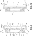
- FIG. 9 is a cross-sectional view illustrating the rail member 22, a reinforcing member 500 and a first bracket 502 of the slide rail mechanism according to a third example not forming part of the present invention.
- the difference between the slide rail mechanism of the third example and previous slide rail mechanisms is that: a first supporting portion 504 of the first bracket 502 includes a plurality of first intermediate sections 506 connected between a first supporting section 508 and a second supporting section 510, and/or a second supporting portion 512 of the first bracket 502 includes a plurality of second intermediate sections 514 connected between a third supporting section 516 and a fourth supporting section 518.
- the plurality of first intermediate sections 506 are bent to be folded relative each other, and the plurality of second intermediate sections 514 are also bent to be folded relative each other. According to the above arrangement, the structural strength of the rail member 22, the reinforcing member 500 and the first bracket 502 supporting each other is improved.
- a first wall portion 520a of the reinforcing member 500 includes a first wall section Y1 and a second wall section Y2 bent relative to the first wall section Y1.
- a space 522 is defined by the first wall section Y1 and the second wall section Y2.
- a second wall portion 520b of the reinforcing member 500 includes a third wall section Y3 and a fourth wall section Y4 bent relative to the third wall section Y3.
- a space 524 is define by the third wall section Y3 and the fourth wall section Y4.
- the plurality of first intermediate sections 506 of the first bracket 502 are connected between the first supporting section 508 and the second supporting section 510.
- the first supporting section 508 of the first bracket 502 and the first rail portion 30a of the rail member 22 are able to support each other.
- a longitudinal supporting portion 503 of the first bracket 502 and the first wall portion 520a of the reinforcing member 500 are able to support each other.
- the second supporting section 510 of the first bracket 502 and the first wall portion 520a of the reinforcing member 500 are able to support each other, and the plurality of first intermediate sections 506 are extended into the space 522 of the first wall portion 520a of the reinforcing member 500, to further improve the structural strength of the reinforcing member 500 and the rail member 22.
- the plurality of second intermediate sections 514 of the first bracket 502 are connected between the third supporting section 516 and the fourth supporting section 518.
- the third supporting section 516 of the first bracket 502 and the second rail portion 30b and the rail member 22 are able to support each other.
- the longitudinal supporting portion 503 of the first bracket 502 and the second wall portion 520b of the reinforcing member 500 are able to support each other.
- the fourth supporting section 518 of the first bracket 502 and the second wall portion 520b of the reinforcing member 500 are able to support each other, and the plurality of second intermediate sections 514 are extended into the space 524 of the second wall portion 520b of the reinforcing member 500, to further improved the structural strength of the reinforcing member 500 and the rail member 22.
- the reinforcing member 500, the first bracket 502 and the rail member 22 of the third example are able to support each other, such that the structural strength of the slide rail mechanism are also improved.
- the third example does not form part of the invention but is useful for understanding the invention.
- FIG. 10 is a cross-sectional view illustrating the rail member 22, the reinforcing member 500 and a first bracket 600 of the slide rail mechanism according to a fourth example not according to the present invention.
- the difference between the slide rail mechanism of the fourth example and the slide rail mechanisms of the third example is that: a first supporting portion 602 of the first bracket 600 includes a first bending section 604, and the first bending section 604 and the lateral side of the first rail portion 30a of the rail member 22 are able to support each other.
- a second supporting portion 606 of the first bracket 600 includes a second bending section 608, and the second bending section 608 and the lateral side of the second rail portion 30b of the rail member 22 are able to support each other.
- the first bracket 600 of the fourth example and the lateral side of the first rail portion 30a of the rail member 22 are able to support each other through the first banding section 604, and the first bracket 600 and the lateral side of the second rail portion 30b of the rail member 22 are able to support each other through the second bending section 608.
- the support reliability of the rail member 22, the first bracket 600 and the reinforcing member 500 is improved, and the structural strength of the slide rail mechanism is also improved.
- the fourth example does not form part of the invention but is useful for understanding the invention.
Landscapes
- Engineering & Computer Science (AREA)
- General Engineering & Computer Science (AREA)
- Mechanical Engineering (AREA)
- Computer Hardware Design (AREA)
- Microelectronics & Electronic Packaging (AREA)
- Drawers Of Furniture (AREA)
Claims (3)
- Gleitschienenmechanismus, welcher umfasst:ein Schienenelement (22);eine erste Halterung (300, 400), die relativ zu dem Schienenelement (22) beweglich ist; undein Verstärkungselement (26), das zwischen dem Schienenelement (22) und der ersten Halterung (300, 400) angeordnet ist;wobei, wenn die erste Halterung (300, 400) bewegt und auf eine beliebige Position eingestellt wird, die erste Halterung (300, 400), das Schienenelement (22) und das Verstärkungselement (26) sich gegenseitig stützen;worin das Schienenelement (22) einen ersten Schienenbereich (30a), einen zweiten Schienenbereich (30b) und einen Längskörper (32) umfasst, der zwischen dem ersten Schienenbereich (30a) und dem zweiten Schienenbereich (30b) verbunden ist, wobei die erste Halterung (300, 400) einen ersten Stützbereich (34a, 402), einen zweiten Stützbereich (34b, 4046) und einen Längsstützbereich (301), der zwischen dem ersten Stützbereich (34a, 402) und dem zweiten Stützbereich (34b, 404) verbunden ist, das Verstärkungselement (26) einen ersten Wandbereich (52a), einen zweiten Wandbereich (52b) und eine Längswand (54) umfasst, die zwischen dem ersten Wandbereich (52a) und dem zweiten Wandbereich (52b) verbunden ist;wobei der erste Wandbereich (52a) des Verstärkungselements (26) einen ersten Wandabschnitt (X1) und einen zweiten Wandabschnitt (X2) umfasst, der relativ zu dem ersten Wandabschnitt (X1) gekrümmt ist, wobei der zweite Wandbereich (52b) des Verstärkungselements (26) einen dritten Wandabschnitt (X3) und einen vierten Wandabschnitt (X4) umfasst, der relativ zu dem dritten Wandabschnitt (X3) gekrümmt ist;wobei der erste Stützbereich (34a, 402) der ersten Halterung (300, 400) ferner einen ersten gekrümmten Abschnitt (302, 406) umfasst, wobei der erste gekrümmte Abschnitt (302, 406) und eine seitliche Seite des ersten Schienenbereichs (30a) des Schienenelements (22) sich gegenseitig stützen können, der zweite Stützbereich (34b, 404) der ersten Halterung (300, 400) ferner einen zweiten gekrümmten Abschnitt (304, 408) umfasst, wobei der zweite gekrümmte Abschnitt (304, 408) und eine seitliche Seite des zweiten Schienenbereichs (30b) des Schienenelements (22) sich gegenseitig stützen können;dadurch gekennzeichnet, dass das Schienenelement (22) eine erste Seite (S1) und eine zweite Seite (S2) aufweist, das Verstärkungselement (26) mit der ersten Seite (S1) verbunden ist, der Gleitschienenmechanismus ferner mindestens eine bewegliche Schiene (50) umfasst, die beweglich an der zweiten Seite (S2) angebracht ist.
- Gleitschienenmechanismus nach Anspruch 1, dadurch gekennzeichnet, dass die erste Halterung (300, 400) zu einem ersten Endbereich (E1) des Schienenelements (22) benachbart angeordnet ist, die erste Halterung (300, 400) einen ersten Befestigungsbereich (38) umfasst, der Gleitschienenmechanismus ferner eine zweite Halterung (28) umfasst, die zu einem zweiten Endbereich (E2) des Schienenelements (22) benachbart angeordnet ist, die zweite Halterung (28) einen zweiten Befestigungsbereich (42) umfasst, und darin dass der erste Befestigungsbereich (38) der ersten Halterung (300, 400) ausgestaltet ist, das Schienenelement (22) an einer ersten Säule (48a) zu befestigen, sowie dass der zweite Befestigungsbereich (42) der zweiten Halterung (28) ausgestaltet ist, das Schienenelement (22) an einer zweiten Säule (48b) zu befestigen.
- Gleitschienenmechanismus nach einem der Ansprüche 1 bis 3, dadurch gekennzeichnet, dass der erste Stützbereich (34a) der ersten Halterung (300) einen ersten Stützabschnitt (K1), einen zweiten Stützabschnitt (K2) und einen ersten Zwischenabschnitt (M1) umfasst, der zwischen dem ersten Stützabschnitt (K1) und dem zweiten Stützabschnitt (K2) verbunden ist, der erste Stützabschnitt (K1) der ersten Halterung (300) und der erste Schienenbereich (30a) des Schienenelements (22) sich gegenseitig stützen können, und darin dass der zweite Stützabschnitt (K2) der ersten Halterung (300) und der erste Wandbereich (52a) des Verstärkungselements (26) sich gegenseitig stützen können.
Applications Claiming Priority (2)
| Application Number | Priority Date | Filing Date | Title |
|---|---|---|---|
| TW108127109A TWI704891B (zh) | 2019-07-29 | 2019-07-29 | 滑軌機構 |
| EP19207863.2A EP3772243B1 (de) | 2019-07-29 | 2019-11-08 | Gleitschienenanordnung und halterungsvorrichtung dafür |
Related Parent Applications (2)
| Application Number | Title | Priority Date | Filing Date |
|---|---|---|---|
| EP19207863.2A Division EP3772243B1 (de) | 2019-07-29 | 2019-11-08 | Gleitschienenanordnung und halterungsvorrichtung dafür |
| EP19207863.2A Division-Into EP3772243B1 (de) | 2019-07-29 | 2019-11-08 | Gleitschienenanordnung und halterungsvorrichtung dafür |
Publications (2)
| Publication Number | Publication Date |
|---|---|
| EP3829276A1 EP3829276A1 (de) | 2021-06-02 |
| EP3829276B1 true EP3829276B1 (de) | 2023-05-24 |
Family
ID=68501356
Family Applications (2)
| Application Number | Title | Priority Date | Filing Date |
|---|---|---|---|
| EP19207863.2A Active EP3772243B1 (de) | 2019-07-29 | 2019-11-08 | Gleitschienenanordnung und halterungsvorrichtung dafür |
| EP21151345.2A Active EP3829276B1 (de) | 2019-07-29 | 2019-11-08 | Gleitschienenmechanismus |
Family Applications Before (1)
| Application Number | Title | Priority Date | Filing Date |
|---|---|---|---|
| EP19207863.2A Active EP3772243B1 (de) | 2019-07-29 | 2019-11-08 | Gleitschienenanordnung und halterungsvorrichtung dafür |
Country Status (4)
| Country | Link |
|---|---|
| US (1) | US10871186B1 (de) |
| EP (2) | EP3772243B1 (de) |
| JP (1) | JP6890167B2 (de) |
| TW (1) | TWI704891B (de) |
Families Citing this family (2)
| Publication number | Priority date | Publication date | Assignee | Title |
|---|---|---|---|---|
| TWI739718B (zh) * | 2021-03-10 | 2021-09-11 | 川湖科技股份有限公司 | 滑軌機構及其滑軌套件 |
| DE102022109787A1 (de) * | 2022-04-22 | 2023-10-26 | Schock Metallwerk Gmbh. | Auszugführung |
Family Cites Families (16)
| Publication number | Priority date | Publication date | Assignee | Title |
|---|---|---|---|---|
| US6230903B1 (en) | 1999-10-27 | 2001-05-15 | Hewlett-Packard Company | Snap-on rack slide mounting system |
| TWI233342B (en) * | 2001-10-12 | 2005-06-01 | Accuride Int Inc | Three member thin drawer slide |
| TWI361651B (en) | 2008-05-16 | 2012-04-01 | King Slide Works Co Ltd | Bracket for a slide assembly |
| CN101721057A (zh) | 2008-10-22 | 2010-06-09 | 大讯科技股份有限公司 | 超薄滑轨 |
| TWI481364B (zh) | 2012-12-24 | 2015-04-21 | King Slide Works Co Ltd | 用於機架系統的滑軌總成 |
| CN104507297B (zh) | 2014-11-26 | 2017-12-22 | 雅固拉国际精密工业(苏州)有限公司 | 一种滑轨支架 |
| US9328769B1 (en) | 2015-01-27 | 2016-05-03 | King Slide Works Co., Ltd. | Slide rail assembly and bracket device thereof |
| US9861197B2 (en) * | 2015-02-13 | 2018-01-09 | King Slide Works Co., Ltd. | Slide rail assembly |
| TWI607722B (zh) * | 2015-05-15 | 2017-12-11 | 川湖科技股份有限公司 | 滑軌總成 |
| CN106604596B (zh) | 2015-10-16 | 2019-03-26 | 川湖科技股份有限公司 | 滑轨总成及其托架装置 |
| US10117352B2 (en) * | 2016-01-06 | 2018-10-30 | King Slide Works Co., Ltd. | Slide rail assembly |
| CN205378453U (zh) | 2016-01-21 | 2016-07-06 | 泛亚电子工业(无锡)有限公司 | 加强型滑轨背架结构 |
| CN205356912U (zh) | 2016-01-24 | 2016-06-29 | 雅固拉国际精密工业(苏州)有限公司 | 滑轨支架 |
| TWI594712B (zh) * | 2016-06-16 | 2017-08-11 | 川湖科技股份有限公司 | 軌件的支撐裝置 |
| TWI610639B (zh) * | 2016-11-22 | 2018-01-11 | 川湖科技股份有限公司 | 滑軌總成 |
| CN110572976B (zh) | 2017-01-19 | 2020-12-18 | 川湖科技股份有限公司 | 滑轨机构及其托架装置 |
-
2019
- 2019-07-29 TW TW108127109A patent/TWI704891B/zh active
- 2019-10-04 US US16/592,776 patent/US10871186B1/en active Active
- 2019-11-08 EP EP19207863.2A patent/EP3772243B1/de active Active
- 2019-11-08 EP EP21151345.2A patent/EP3829276B1/de active Active
- 2019-11-19 JP JP2019208352A patent/JP6890167B2/ja active Active
Also Published As
| Publication number | Publication date |
|---|---|
| EP3772243A1 (de) | 2021-02-03 |
| US10871186B1 (en) | 2020-12-22 |
| EP3829276A1 (de) | 2021-06-02 |
| TW202103606A (zh) | 2021-02-01 |
| EP3772243B1 (de) | 2021-08-04 |
| JP6890167B2 (ja) | 2021-06-18 |
| JP2021020041A (ja) | 2021-02-18 |
| TWI704891B (zh) | 2020-09-21 |
Similar Documents
| Publication | Publication Date | Title |
|---|---|---|
| EP3094165B1 (de) | Gleitschienenanordnung | |
| JP6660359B2 (ja) | スライドレール機構 | |
| TWI552670B (zh) | 滑軌總成及其托架裝置 | |
| EP3352547B1 (de) | Gleitschienenanordnung | |
| EP3829276B1 (de) | Gleitschienenmechanismus | |
| US9861197B2 (en) | Slide rail assembly | |
| EP3826441A1 (de) | Gleitschienenmechanismus | |
| US20170367207A1 (en) | Rack system and slide rail assemblies thereof | |
| EP3273757B1 (de) | Gleitschienenanordnung für regalsystem | |
| JP2019051292A (ja) | ラックシステム及びそのスライドレールアセンブリ | |
| EP3841919A1 (de) | Gestellsystem und gleitschienenanordnungen daraus | |
| TW201424631A (zh) | 用於機架系統的滑軌總成 | |
| EP4057786B1 (de) | Gleitschienenmechanismus und gleitschienenkit dafür | |
| EP3914057B1 (de) | Gleitschienenanordnung | |
| JP3174265U (ja) | ブラケット及びスライドレールの支持構造 | |
| JP2019102786A (ja) | ラックに適した支持アセンブリ | |
| JP2021023781A (ja) | スライドレール組立体 | |
| CN211368490U (zh) | 一种新型道路用限高装置 | |
| TWI544853B (zh) | 滑軌總成 | |
| CN112312713A (zh) | 滑轨机构 | |
| CN115076232A (zh) | 滑轨机构及其滑轨套件 | |
| CN103185069B (zh) | 托架与滑轨的支撑构造 | |
| JP2001329771A (ja) | シャッターケースのブラケット | |
| CN119730128A (zh) | 支撑总成 | |
| CN114449828A (zh) | 滑轨总成 |
Legal Events
| Date | Code | Title | Description |
|---|---|---|---|
| PUAI | Public reference made under article 153(3) epc to a published international application that has entered the european phase |
Free format text: ORIGINAL CODE: 0009012 |
|
| STAA | Information on the status of an ep patent application or granted ep patent |
Free format text: STATUS: THE APPLICATION HAS BEEN PUBLISHED |
|
| AC | Divisional application: reference to earlier application |
Ref document number: 3772243 Country of ref document: EP Kind code of ref document: P |
|
| AK | Designated contracting states |
Kind code of ref document: A1 Designated state(s): AL AT BE BG CH CY CZ DE DK EE ES FI FR GB GR HR HU IE IS IT LI LT LU LV MC MK MT NL NO PL PT RO RS SE SI SK SM TR |
|
| STAA | Information on the status of an ep patent application or granted ep patent |
Free format text: STATUS: REQUEST FOR EXAMINATION WAS MADE |
|
| 17P | Request for examination filed |
Effective date: 20210617 |
|
| RBV | Designated contracting states (corrected) |
Designated state(s): AL AT BE BG CH CY CZ DE DK EE ES FI FR GB GR HR HU IE IS IT LI LT LU LV MC MK MT NL NO PL PT RO RS SE SI SK SM TR |
|
| STAA | Information on the status of an ep patent application or granted ep patent |
Free format text: STATUS: EXAMINATION IS IN PROGRESS |
|
| 17Q | First examination report despatched |
Effective date: 20211202 |
|
| GRAP | Despatch of communication of intention to grant a patent |
Free format text: ORIGINAL CODE: EPIDOSNIGR1 |
|
| STAA | Information on the status of an ep patent application or granted ep patent |
Free format text: STATUS: GRANT OF PATENT IS INTENDED |
|
| INTG | Intention to grant announced |
Effective date: 20221221 |
|
| GRAS | Grant fee paid |
Free format text: ORIGINAL CODE: EPIDOSNIGR3 |
|
| GRAA | (expected) grant |
Free format text: ORIGINAL CODE: 0009210 |
|
| STAA | Information on the status of an ep patent application or granted ep patent |
Free format text: STATUS: THE PATENT HAS BEEN GRANTED |
|
| AC | Divisional application: reference to earlier application |
Ref document number: 3772243 Country of ref document: EP Kind code of ref document: P |
|
| AK | Designated contracting states |
Kind code of ref document: B1 Designated state(s): AL AT BE BG CH CY CZ DE DK EE ES FI FR GB GR HR HU IE IS IT LI LT LU LV MC MK MT NL NO PL PT RO RS SE SI SK SM TR |
|
| REG | Reference to a national code |
Ref country code: GB Ref legal event code: FG4D |
|
| REG | Reference to a national code |
Ref country code: CH Ref legal event code: EP |
|
| REG | Reference to a national code |
Ref country code: DE Ref legal event code: R096 Ref document number: 602019029418 Country of ref document: DE |
|
| REG | Reference to a national code |
Ref country code: AT Ref legal event code: REF Ref document number: 1570404 Country of ref document: AT Kind code of ref document: T Effective date: 20230615 |
|
| REG | Reference to a national code |
Ref country code: IE Ref legal event code: FG4D |
|
| REG | Reference to a national code |
Ref country code: LT Ref legal event code: MG9D |
|
| REG | Reference to a national code |
Ref country code: NL Ref legal event code: MP Effective date: 20230524 |
|
| REG | Reference to a national code |
Ref country code: AT Ref legal event code: MK05 Ref document number: 1570404 Country of ref document: AT Kind code of ref document: T Effective date: 20230524 |
|
| PG25 | Lapsed in a contracting state [announced via postgrant information from national office to epo] |
Ref country code: SE Free format text: LAPSE BECAUSE OF FAILURE TO SUBMIT A TRANSLATION OF THE DESCRIPTION OR TO PAY THE FEE WITHIN THE PRESCRIBED TIME-LIMIT Effective date: 20230524 Ref country code: PT Free format text: LAPSE BECAUSE OF FAILURE TO SUBMIT A TRANSLATION OF THE DESCRIPTION OR TO PAY THE FEE WITHIN THE PRESCRIBED TIME-LIMIT Effective date: 20230925 Ref country code: NO Free format text: LAPSE BECAUSE OF FAILURE TO SUBMIT A TRANSLATION OF THE DESCRIPTION OR TO PAY THE FEE WITHIN THE PRESCRIBED TIME-LIMIT Effective date: 20230824 Ref country code: NL Free format text: LAPSE BECAUSE OF FAILURE TO SUBMIT A TRANSLATION OF THE DESCRIPTION OR TO PAY THE FEE WITHIN THE PRESCRIBED TIME-LIMIT Effective date: 20230524 Ref country code: ES Free format text: LAPSE BECAUSE OF FAILURE TO SUBMIT A TRANSLATION OF THE DESCRIPTION OR TO PAY THE FEE WITHIN THE PRESCRIBED TIME-LIMIT Effective date: 20230524 Ref country code: AT Free format text: LAPSE BECAUSE OF FAILURE TO SUBMIT A TRANSLATION OF THE DESCRIPTION OR TO PAY THE FEE WITHIN THE PRESCRIBED TIME-LIMIT Effective date: 20230524 |
|
| PG25 | Lapsed in a contracting state [announced via postgrant information from national office to epo] |
Ref country code: RS Free format text: LAPSE BECAUSE OF FAILURE TO SUBMIT A TRANSLATION OF THE DESCRIPTION OR TO PAY THE FEE WITHIN THE PRESCRIBED TIME-LIMIT Effective date: 20230524 Ref country code: PL Free format text: LAPSE BECAUSE OF FAILURE TO SUBMIT A TRANSLATION OF THE DESCRIPTION OR TO PAY THE FEE WITHIN THE PRESCRIBED TIME-LIMIT Effective date: 20230524 Ref country code: LV Free format text: LAPSE BECAUSE OF FAILURE TO SUBMIT A TRANSLATION OF THE DESCRIPTION OR TO PAY THE FEE WITHIN THE PRESCRIBED TIME-LIMIT Effective date: 20230524 Ref country code: LT Free format text: LAPSE BECAUSE OF FAILURE TO SUBMIT A TRANSLATION OF THE DESCRIPTION OR TO PAY THE FEE WITHIN THE PRESCRIBED TIME-LIMIT Effective date: 20230524 Ref country code: IS Free format text: LAPSE BECAUSE OF FAILURE TO SUBMIT A TRANSLATION OF THE DESCRIPTION OR TO PAY THE FEE WITHIN THE PRESCRIBED TIME-LIMIT Effective date: 20230924 Ref country code: HR Free format text: LAPSE BECAUSE OF FAILURE TO SUBMIT A TRANSLATION OF THE DESCRIPTION OR TO PAY THE FEE WITHIN THE PRESCRIBED TIME-LIMIT Effective date: 20230524 Ref country code: GR Free format text: LAPSE BECAUSE OF FAILURE TO SUBMIT A TRANSLATION OF THE DESCRIPTION OR TO PAY THE FEE WITHIN THE PRESCRIBED TIME-LIMIT Effective date: 20230825 |
|
| PG25 | Lapsed in a contracting state [announced via postgrant information from national office to epo] |
Ref country code: FI Free format text: LAPSE BECAUSE OF FAILURE TO SUBMIT A TRANSLATION OF THE DESCRIPTION OR TO PAY THE FEE WITHIN THE PRESCRIBED TIME-LIMIT Effective date: 20230524 |
|
| PG25 | Lapsed in a contracting state [announced via postgrant information from national office to epo] |
Ref country code: SK Free format text: LAPSE BECAUSE OF FAILURE TO SUBMIT A TRANSLATION OF THE DESCRIPTION OR TO PAY THE FEE WITHIN THE PRESCRIBED TIME-LIMIT Effective date: 20230524 |
|
| PG25 | Lapsed in a contracting state [announced via postgrant information from national office to epo] |
Ref country code: SM Free format text: LAPSE BECAUSE OF FAILURE TO SUBMIT A TRANSLATION OF THE DESCRIPTION OR TO PAY THE FEE WITHIN THE PRESCRIBED TIME-LIMIT Effective date: 20230524 Ref country code: SK Free format text: LAPSE BECAUSE OF FAILURE TO SUBMIT A TRANSLATION OF THE DESCRIPTION OR TO PAY THE FEE WITHIN THE PRESCRIBED TIME-LIMIT Effective date: 20230524 Ref country code: RO Free format text: LAPSE BECAUSE OF FAILURE TO SUBMIT A TRANSLATION OF THE DESCRIPTION OR TO PAY THE FEE WITHIN THE PRESCRIBED TIME-LIMIT Effective date: 20230524 Ref country code: EE Free format text: LAPSE BECAUSE OF FAILURE TO SUBMIT A TRANSLATION OF THE DESCRIPTION OR TO PAY THE FEE WITHIN THE PRESCRIBED TIME-LIMIT Effective date: 20230524 Ref country code: DK Free format text: LAPSE BECAUSE OF FAILURE TO SUBMIT A TRANSLATION OF THE DESCRIPTION OR TO PAY THE FEE WITHIN THE PRESCRIBED TIME-LIMIT Effective date: 20230524 Ref country code: CZ Free format text: LAPSE BECAUSE OF FAILURE TO SUBMIT A TRANSLATION OF THE DESCRIPTION OR TO PAY THE FEE WITHIN THE PRESCRIBED TIME-LIMIT Effective date: 20230524 |
|
| REG | Reference to a national code |
Ref country code: DE Ref legal event code: R097 Ref document number: 602019029418 Country of ref document: DE |
|
| PLBE | No opposition filed within time limit |
Free format text: ORIGINAL CODE: 0009261 |
|
| STAA | Information on the status of an ep patent application or granted ep patent |
Free format text: STATUS: NO OPPOSITION FILED WITHIN TIME LIMIT |
|
| 26N | No opposition filed |
Effective date: 20240227 |
|
| PG25 | Lapsed in a contracting state [announced via postgrant information from national office to epo] |
Ref country code: SI Free format text: LAPSE BECAUSE OF FAILURE TO SUBMIT A TRANSLATION OF THE DESCRIPTION OR TO PAY THE FEE WITHIN THE PRESCRIBED TIME-LIMIT Effective date: 20230524 |
|
| PG25 | Lapsed in a contracting state [announced via postgrant information from national office to epo] |
Ref country code: SI Free format text: LAPSE BECAUSE OF FAILURE TO SUBMIT A TRANSLATION OF THE DESCRIPTION OR TO PAY THE FEE WITHIN THE PRESCRIBED TIME-LIMIT Effective date: 20230524 Ref country code: IT Free format text: LAPSE BECAUSE OF FAILURE TO SUBMIT A TRANSLATION OF THE DESCRIPTION OR TO PAY THE FEE WITHIN THE PRESCRIBED TIME-LIMIT Effective date: 20230524 |
|
| REG | Reference to a national code |
Ref country code: CH Ref legal event code: PL |
|
| PG25 | Lapsed in a contracting state [announced via postgrant information from national office to epo] |
Ref country code: MC Free format text: LAPSE BECAUSE OF FAILURE TO SUBMIT A TRANSLATION OF THE DESCRIPTION OR TO PAY THE FEE WITHIN THE PRESCRIBED TIME-LIMIT Effective date: 20230524 |
|
| PG25 | Lapsed in a contracting state [announced via postgrant information from national office to epo] |
Ref country code: LU Free format text: LAPSE BECAUSE OF NON-PAYMENT OF DUE FEES Effective date: 20231108 |
|
| PG25 | Lapsed in a contracting state [announced via postgrant information from national office to epo] |
Ref country code: CH Free format text: LAPSE BECAUSE OF NON-PAYMENT OF DUE FEES Effective date: 20231130 |
|
| PG25 | Lapsed in a contracting state [announced via postgrant information from national office to epo] |
Ref country code: MC Free format text: LAPSE BECAUSE OF FAILURE TO SUBMIT A TRANSLATION OF THE DESCRIPTION OR TO PAY THE FEE WITHIN THE PRESCRIBED TIME-LIMIT Effective date: 20230524 Ref country code: LU Free format text: LAPSE BECAUSE OF NON-PAYMENT OF DUE FEES Effective date: 20231108 Ref country code: CH Free format text: LAPSE BECAUSE OF NON-PAYMENT OF DUE FEES Effective date: 20231130 |
|
| REG | Reference to a national code |
Ref country code: BE Ref legal event code: MM Effective date: 20231130 |
|
| REG | Reference to a national code |
Ref country code: DE Ref legal event code: R082 Ref document number: 602019029418 Country of ref document: DE Representative=s name: STRAUS, ALEXANDER, DIPL.-CHEM.UNIV. DR.PHIL., DE |
|
| PG25 | Lapsed in a contracting state [announced via postgrant information from national office to epo] |
Ref country code: BE Free format text: LAPSE BECAUSE OF NON-PAYMENT OF DUE FEES Effective date: 20231130 |
|
| PG25 | Lapsed in a contracting state [announced via postgrant information from national office to epo] |
Ref country code: FR Free format text: LAPSE BECAUSE OF NON-PAYMENT OF DUE FEES Effective date: 20231130 |
|
| PG25 | Lapsed in a contracting state [announced via postgrant information from national office to epo] |
Ref country code: FR Free format text: LAPSE BECAUSE OF NON-PAYMENT OF DUE FEES Effective date: 20231130 Ref country code: BE Free format text: LAPSE BECAUSE OF NON-PAYMENT OF DUE FEES Effective date: 20231130 |
|
| PG25 | Lapsed in a contracting state [announced via postgrant information from national office to epo] |
Ref country code: BG Free format text: LAPSE BECAUSE OF FAILURE TO SUBMIT A TRANSLATION OF THE DESCRIPTION OR TO PAY THE FEE WITHIN THE PRESCRIBED TIME-LIMIT Effective date: 20230524 |
|
| PG25 | Lapsed in a contracting state [announced via postgrant information from national office to epo] |
Ref country code: BG Free format text: LAPSE BECAUSE OF FAILURE TO SUBMIT A TRANSLATION OF THE DESCRIPTION OR TO PAY THE FEE WITHIN THE PRESCRIBED TIME-LIMIT Effective date: 20230524 |
|
| PG25 | Lapsed in a contracting state [announced via postgrant information from national office to epo] |
Ref country code: CY Free format text: LAPSE BECAUSE OF FAILURE TO SUBMIT A TRANSLATION OF THE DESCRIPTION OR TO PAY THE FEE WITHIN THE PRESCRIBED TIME-LIMIT; INVALID AB INITIO Effective date: 20191108 |
|
| PG25 | Lapsed in a contracting state [announced via postgrant information from national office to epo] |
Ref country code: HU Free format text: LAPSE BECAUSE OF FAILURE TO SUBMIT A TRANSLATION OF THE DESCRIPTION OR TO PAY THE FEE WITHIN THE PRESCRIBED TIME-LIMIT; INVALID AB INITIO Effective date: 20191108 |
|
| PGFP | Annual fee paid to national office [announced via postgrant information from national office to epo] |
Ref country code: GB Payment date: 20250909 Year of fee payment: 7 |
|
| PGFP | Annual fee paid to national office [announced via postgrant information from national office to epo] |
Ref country code: IE Payment date: 20250909 Year of fee payment: 7 |
|
| PG25 | Lapsed in a contracting state [announced via postgrant information from national office to epo] |
Ref country code: TR Free format text: LAPSE BECAUSE OF FAILURE TO SUBMIT A TRANSLATION OF THE DESCRIPTION OR TO PAY THE FEE WITHIN THE PRESCRIBED TIME-LIMIT Effective date: 20230524 |
|
| PGFP | Annual fee paid to national office [announced via postgrant information from national office to epo] |
Ref country code: DE Payment date: 20250910 Year of fee payment: 7 |