EP3828126A1 - Dispositif de transport et/ou de dépô et utilisation - Google Patents
Dispositif de transport et/ou de dépô et utilisation Download PDFInfo
- Publication number
- EP3828126A1 EP3828126A1 EP20000426.5A EP20000426A EP3828126A1 EP 3828126 A1 EP3828126 A1 EP 3828126A1 EP 20000426 A EP20000426 A EP 20000426A EP 3828126 A1 EP3828126 A1 EP 3828126A1
- Authority
- EP
- European Patent Office
- Prior art keywords
- support means
- holding
- fork
- longitudinal
- tensioning
- Prior art date
- Legal status (The legal status is an assumption and is not a legal conclusion. Google has not performed a legal analysis and makes no representation as to the accuracy of the status listed.)
- Withdrawn
Links
Images


Classifications
-
- B—PERFORMING OPERATIONS; TRANSPORTING
- B66—HOISTING; LIFTING; HAULING
- B66F—HOISTING, LIFTING, HAULING OR PUSHING, NOT OTHERWISE PROVIDED FOR, e.g. DEVICES WHICH APPLY A LIFTING OR PUSHING FORCE DIRECTLY TO THE SURFACE OF A LOAD
- B66F9/00—Devices for lifting or lowering bulky or heavy goods for loading or unloading purposes
- B66F9/06—Devices for lifting or lowering bulky or heavy goods for loading or unloading purposes movable, with their loads, on wheels or the like, e.g. fork-lift trucks
- B66F9/075—Constructional features or details
- B66F9/12—Platforms; Forks; Other load supporting or gripping members
- B66F9/18—Load gripping or retaining means
Definitions
- the invention relates to a device for transporting and / or depositing according to the preamble of claim 1, a use according to the preamble of claim 9 and a method for using a device according to the preamble of claim 10.
- a lowering device is lowered into a floor recess in order to load an air freight pallet piece by piece, there is also a risk of falling for the employees, the load platform solution is unsafe, not portable, structurally partially not retrofittable and very cost-intensive.
- the object of the present invention is to provide a simple and safe device for transporting and / or storing a surrounding device.
- a device for transporting and / or depositing a surrounding device for wrapping a transport item, in particular a surrounding net means, for attachment to a fork carrier means of an industrial truck, in particular a forklift truck, in particular the forks of a forklift truck, comprising a carrier means that has a longitudinal carrier means and a cross member , the transverse support means being arranged on a front area of the longitudinal support means, the longitudinal support means being attachable to a rear support area on the fork support means, in particular being able to be pushed onto the fork prongs, the transverse support means having holding means for holding the enclosing device, which can be tilted via a longitudinal shaft means on the transverse support means so that the surrounding device can be picked up and / or put down, with a tensioning unit for the holding means for picking up the surrounding device, with a triggering unit for triggering d he tensioning unit for the holding means for putting down the encircling device, in particular in the event of
- the invention provides a device that is easy to install and yet safe for the operator.
- the device can be attached to an industrial truck, in particular a forklift truck, in particular designed to be mountable for a forklift truck, in particular a support frame that can be mounted for a forklift truck with fork prongs.
- the device is designed to accommodate a surrounding device on its shovels and to place it safely over the goods being transported by the lifting and driving movements of the forklift truck.
- the holding means can advantageously be folded down by means of a secure release mechanism. Only one employee is required for pulling on and securing the enclosing device, who is safely seated in the forklift cabin during the securing process of the enclosing device.
- the triggering process in order to throw off the enclosing device behind the goods to be transported can be done from the forklift cabin. It is no longer necessary to expose an employee to risky high lifting heights and to associate them directly with the dangers of the surrounding device.
- the safety functions of the enclosing device prevent damage to the goods being transported and accidents greatly reduced.
- the enclosing device is designed to be parkable, so the forklift truck can thus be used for all steps, from loading, securing and transporting an air freight pallet. Thanks to its modular design, the device can be scaled in length and width to suit the respective goods.
- the number and shape of the holding means can also be individually adapted to the wishes of the customer.
- the release system could be expanded from the mechanical version to an electrical or hydraulic solution.
- the device can be placed on two, in particular four, feet, in particular two front foldable feet.
- the device can thus be separated from the fork prongs by feet and placed on a flat surface.
- the device can be connected to the fork prongs in a non-slip manner by means of a safety device, in particular a bolt safety device on entry pockets.
- the device can be used to extend a basic fork length depending on the model.
- Several blades are attached to a cross member on a shaft, which in an operating position are approximately horizontally forward. The blades were advantageously designed in such a way that their shape minimizes the hazard potential.
- the shaft with holding means in particular shovels
- the shaft with holding means can be folded down at approximately 180 ° from the floor or from the driver's cab.
- a release mechanism can be triggered automatically so as not to damage either the goods on the air freight pallet or the device.
- the maximum force until the overload protection is triggered can advantageously be set using a compression spring.
- the cross member and the complete release unit can advantageously be designed to be screwable.
- the outer dimensions of the device can be combined compactly in order to make it transportable for trucks.
- this design allows defective components to be replaced or repaired in the shortest possible time.
- a release band which can be used to release the release unit, can be attached to the truck by a magnet, in particular self-rolling or self-unwinding. This prevents the forklift driver from driving over the release belt when maneuvering, regardless of the mast position and fork height.
- the tensioning unit for the holding means is designed as a tensioning slide for tensioning by means of a tensioning and / or triggering means and the tensioning spring.
- the rear support area of the longitudinal support means attached to the fork support means is to be secured by means of a securing means, in particular with a tine securing bolt.
- the cross member has holding means in the form of blade means, which in particular has a rounded shape, It is advantageous if at least one holding means, in particular a shovel means, can be secured by means of a predetermined breaking point.
- the carrier means can be set up by means of feet, in particular four feet, in particular with a front, foldable pair of feet.
- transverse support means can be removed, in particular unscrewed.
- a device for transporting and / or depositing a surrounding device for wrapping a transport item, in particular a surrounding net means, for attachment to a fork carrier means of an industrial truck, in particular a forklift truck, in particular the fork prongs of a forklift truck comprising a carrier means that has a longitudinal carrier means and comprises a transverse support means, the transverse support means being arranged on a front region of the longitudinal support means, the longitudinal support means being attachable to a rear support region on the fork support means, in particular being able to be pushed onto the fork prongs, the transverse support means having holding means for holding the encircling device, which is attached to the fork support means via a longitudinal shaft means
- Transverse support means are tiltable so that the enclosing device can be picked up and / or put down, in particular according to one of claims 1 to 8, for attachment to and actuation by a floor conveyor er vehicle, in particular forklift vehicle, in particular forks of a
- the object is also achieved by a method for using a device for transporting and / or depositing a enclosing device for wrapping a transport item, in particular an enclosing net, for attachment to a fork carrier of an industrial truck, in particular a forklift truck, in particular forks of a forklift truck, in particular according to one of the claims 1 to 8, wherein a carrier means, which has a longitudinal carrier means and a transverse support means, the transverse support means at a front region of the Longitudinal support means is arranged, the longitudinal support means being attached to a rear support area on the fork support means, in particular being pushed onto the fork prongs, the transverse support means having holding means for holding the encircling device, which can be tilted via a longitudinal shaft means on the transverse support means so that the enclosing device is received and / or is put down, with a tensioning unit for the holding means for receiving the enclosing device, with a triggering unit for triggering
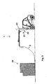
- Fig. 1a shows a device 1 according to the invention for transporting and / or depositing a surrounding device 2 for wrapping a transport item, in particular a surrounding net means 3, for attachment to a fork carrier means 4 of a forklift 5, in particular fork tines of a forklift comprising a carrier means 6, which has a longitudinal carrier means 7 and a Cross member 8, the cross member 8 being arranged on a front area 9 of the longitudinal member 7, the longitudinal member being attachable to a rear member region 10 on the fork carrier means 4, in particular being slidable onto fork prongs, the cross member 8 having holding means 11 for holding the enclosing device 2 , which can be tilted on the transverse support means 8 via a longitudinal shaft means 12, so that the surrounding device 2 can be picked up and / or put down, with a clamping unit 15 for the holding means 11 for picking up the surrounding device 2, with a release unit 19 for releasing the clamping unit 15 for the holding means 11 for
- Figure 1b shows a device according to the invention in a detailed side view with the holding means 11 and stand 14 folded down, the tensioning unit 15 for the holding means 11 being designed as a tensioning slide 16 for tensioning by means of a tensioning and / or triggering means 17 and the tensioning spring 18, the triggering unit 19, in particular has hydraulic and / or electrical and / or mechanical means, for triggering the tensioning unit 15 for the holding means 11 comprises a tensioning cable device 20, in particular a release band 21, which is to be held releasably in particular by means of a fastening means 22, in particular a magnetic means, in particular on a Lifting mast 23 of the forklift, the triggering process being controllable in particular from a forklift cabin, in particular in the event of mechanical overload, in particular by setting a tension spring 18 to set a maximum triggering force
- the clamping slide 16 When the release unit is triggered, the clamping slide 16 is displaced in the direction of the blade means by the force of gravity and the weight of the enclosing device 2. By moving the clamping slide 16, the blade means can rotate on the longitudinal shaft means. The surrounding device 2 is thrown off, shown as an example in Fig. 5 . The swivel angle range of the blade means covers approximately 180 °. This prevents the enclosing device 2 from getting stuck inadvertently.
- the release lever To secure the shovel means again in the horizontal operating position, the release lever must be actuated and the clamping slide 16 moved in the direction of the release lever until the clamping slide 16 rests against its end stop. The tensioning and / or triggering means is then brought into its rest position. The clamping slide 16 is now secured again and ready for operation.
- Figure 1c a device according to the invention in a side view with holding means 11 in a 180 ° position.
- Fig. 1d shows a device 1 according to the invention in a side view with a holding means 11 (not shown), the triggering means 17 having a contact means to an exemplary rounded holding means 27 on the clamping slide 16 in the form of a roller means 26, the roller means 26 ensuring an essentially constant rolling resistance to the holding means 27 , in particular a roller means 26 made of a plastic, whereby a particularly good grip on the holding means is given.
- FIG. 2 , 3rd and 4th show a device 1 according to the invention attached to a forklift 5 in various travel positions, in FIG Fig. 2 the containment means is charged and lifted, brought up to the transported goods, lifted over it, and in Fig. 5 deposed again.
- a surrounding device 2 in particular surrounding net means 3, is connected, for example, on one side to an air freight pallet with transported goods 24, the surrounding device 2 being spread out.
- the device 1 is received by way of example with the fork carrier means 4, in particular fork prongs, of the fork lift truck 5, and is secured by the bolt securing means.
- a tape winder can advantageously be attached to the lifting mast 23 with a magnet.
- Front foldable feet 14 of the device are advantageously folded in a horizontal position, in particular at a 90 ° angle relative to the carrier means 6, and secured by being pushed into a carrier profile of the carrier means 6.
- Shovel means 25 of device 1 are brought into a horizontal operating position.
- the device is moved over the surrounding device 2 until the blades are approximately 1 ⁇ 4 over the spreading out surrounding device 2.
- the encircling device 2 that has been driven over can be hung over the holding means 11, in particular shovel means 25, in particular in a double loop to save space with regard to the maximum lifting mast height.
- the forks are then slowly raised and advantageously at the same time the forklift 5 is moved in the direction of the goods to be transported 24 until the enclosing device 2 rests approximately perpendicularly on the goods to be transported 24 and is advantageously not under tension.
- a trigger unit 19 can be unlocked in the corresponding position and thus the enclosing device 2 can be thrown on and behind the transported goods 24, shown by way of example in FIG Fig. 5 .
- the forklift 5 can be removed from the place of use against the transported goods 24 and the device can be parked and stored at any point, in particular on the feet 13, the folded feet being unfolded again beforehand become.
- the shovel means 25 are held in the horizontal position by the secured clamping slide 16.
- the release unit 19 can be unlocked using the hand lever or the roller hinge. In the sense of an overload unlocking, the release unit is automatically unlocked with normal load by the surrounding device 2 and an additional overload of the clamping slide 16.
- the clamping slide 16 is displaced in the direction of the shovel means by gravity, normal load and overload, and the surrounding device 2 is thrown off.
Landscapes
- Engineering & Computer Science (AREA)
- Transportation (AREA)
- Structural Engineering (AREA)
- Civil Engineering (AREA)
- Life Sciences & Earth Sciences (AREA)
- Geology (AREA)
- Mechanical Engineering (AREA)
- Forklifts And Lifting Vehicles (AREA)
Applications Claiming Priority (1)
| Application Number | Priority Date | Filing Date | Title |
|---|---|---|---|
| DE102019008188.9A DE102019008188A1 (de) | 2019-11-26 | 2019-11-26 | Vorrichtung zum Transportieren und/oder Ablegen, Verwendung und Verfahren |
Publications (1)
| Publication Number | Publication Date |
|---|---|
| EP3828126A1 true EP3828126A1 (fr) | 2021-06-02 |
Family
ID=73598650
Family Applications (1)
| Application Number | Title | Priority Date | Filing Date |
|---|---|---|---|
| EP20000426.5A Withdrawn EP3828126A1 (fr) | 2019-11-26 | 2020-11-25 | Dispositif de transport et/ou de dépô et utilisation |
Country Status (2)
| Country | Link |
|---|---|
| EP (1) | EP3828126A1 (fr) |
| DE (1) | DE102019008188A1 (fr) |
Citations (4)
| Publication number | Priority date | Publication date | Assignee | Title |
|---|---|---|---|---|
| JPH0484297U (fr) * | 1990-11-29 | 1992-07-22 | ||
| JPH0719297U (ja) * | 1993-09-07 | 1995-04-07 | 幸南工業株式会社 | フォークリフトの雨よけ |
| SE507194C2 (sv) * | 1992-06-09 | 1998-04-20 | Sotkamon Teraestyoe Oy | Anordning för utbredning av ett skyddshölje |
| US20140117296A1 (en) * | 2012-10-26 | 2014-05-01 | International Paper Company | System and method for placing a tarpaulin over a load |
-
2019
- 2019-11-26 DE DE102019008188.9A patent/DE102019008188A1/de not_active Withdrawn
-
2020
- 2020-11-25 EP EP20000426.5A patent/EP3828126A1/fr not_active Withdrawn
Patent Citations (4)
| Publication number | Priority date | Publication date | Assignee | Title |
|---|---|---|---|---|
| JPH0484297U (fr) * | 1990-11-29 | 1992-07-22 | ||
| SE507194C2 (sv) * | 1992-06-09 | 1998-04-20 | Sotkamon Teraestyoe Oy | Anordning för utbredning av ett skyddshölje |
| JPH0719297U (ja) * | 1993-09-07 | 1995-04-07 | 幸南工業株式会社 | フォークリフトの雨よけ |
| US20140117296A1 (en) * | 2012-10-26 | 2014-05-01 | International Paper Company | System and method for placing a tarpaulin over a load |
Also Published As
| Publication number | Publication date |
|---|---|
| DE102019008188A1 (de) | 2021-05-27 |
Similar Documents
| Publication | Publication Date | Title |
|---|---|---|
| DE10123991C2 (de) | Handbetriebener Hubstapler | |
| DE102008013973A1 (de) | Handkarre zum Aufnehmen und Verlegen von Plattenelementen | |
| EP2316781A2 (fr) | Tribune de travail pour chariot élévateur à fourche | |
| DE202019005321U1 (de) | Vorrichtung zum Transportieren und/oder Ablegen | |
| DE60017160T2 (de) | Hubwagen | |
| EP3828126A1 (fr) | Dispositif de transport et/ou de dépô et utilisation | |
| EP0581223A1 (fr) | Dispositif de transport et de halage | |
| DE202009014248U1 (de) | Aufbrech- und Transportvorrichtung für Wild | |
| EP1483181B1 (fr) | Conteneur | |
| DE202021003853U1 (de) | Schwenkvorrichtung | |
| DE20008632U1 (de) | Transportwagen | |
| DE1244654B (de) | Transportable Kippvorrichtung fuer Foerderwagen des Bergbaus | |
| DE202007010664U1 (de) | Vorrichtung zum Wenden von Rollwagen | |
| DE60014494T2 (de) | Abdecksystem für Absetzkipper | |
| DE869174C (de) | Zum Laden und Stapeln dienendes Foerdergeraet | |
| DE4010046A1 (de) | Vorrichtung zum manipulieren von verpacktem und unverpacktem formstabilen transportgut | |
| AT328362B (de) | Gabelhubstapler | |
| DE102010056322A1 (de) | Verfahren zum Be- oder Entladen von Transportgut sowie Vorrichtung zur Durchführung des Verfahrens sowie ein für die Vorrichtung nutzbarer Lastgutträger | |
| DE202018104906U1 (de) | Radgewichtmontagevorrichtung | |
| AT389683B (de) | Hubfahrzeug, insbesondere fuer die ver- und entsorgung von flugzeugen | |
| DE3013488C2 (de) | Paketgabel mit Schutzmantel | |
| DE10210818B4 (de) | Haltevorrichtung für Hubschrauber | |
| DE2112290C3 (de) | Verfahrbares, begeh- und/oder befahrbares Gerät zur Überwindung von Höhenunterschieden | |
| DE29521286U1 (de) | Selbstaufladender Hubwagen | |
| DE102021006315A1 (de) | Schwenkvorrichtung |
Legal Events
| Date | Code | Title | Description |
|---|---|---|---|
| PUAI | Public reference made under article 153(3) epc to a published international application that has entered the european phase |
Free format text: ORIGINAL CODE: 0009012 |
|
| STAA | Information on the status of an ep patent application or granted ep patent |
Free format text: STATUS: THE APPLICATION HAS BEEN PUBLISHED |
|
| AK | Designated contracting states |
Kind code of ref document: A1 Designated state(s): AL AT BE BG CH CY CZ DE DK EE ES FI FR GB GR HR HU IE IS IT LI LT LU LV MC MK MT NL NO PL PT RO RS SE SI SK SM TR |
|
| STAA | Information on the status of an ep patent application or granted ep patent |
Free format text: STATUS: REQUEST FOR EXAMINATION WAS MADE |
|
| 17P | Request for examination filed |
Effective date: 20211202 |
|
| RBV | Designated contracting states (corrected) |
Designated state(s): AL AT BE BG CH CY CZ DE DK EE ES FI FR GB GR HR HU IE IS IT LI LT LU LV MC MK MT NL NO PL PT RO RS SE SI SK SM TR |
|
| P01 | Opt-out of the competence of the unified patent court (upc) registered |
Effective date: 20230523 |
|
| STAA | Information on the status of an ep patent application or granted ep patent |
Free format text: STATUS: EXAMINATION IS IN PROGRESS |
|
| 17Q | First examination report despatched |
Effective date: 20240429 |
|
| STAA | Information on the status of an ep patent application or granted ep patent |
Free format text: STATUS: THE APPLICATION IS DEEMED TO BE WITHDRAWN |
|
| 18D | Application deemed to be withdrawn |
Effective date: 20240830 |