EP3823089B1 - Phasenumschalter und elektrische schwenkantenne - Google Patents
Phasenumschalter und elektrische schwenkantenne Download PDFInfo
- Publication number
- EP3823089B1 EP3823089B1 EP19843956.4A EP19843956A EP3823089B1 EP 3823089 B1 EP3823089 B1 EP 3823089B1 EP 19843956 A EP19843956 A EP 19843956A EP 3823089 B1 EP3823089 B1 EP 3823089B1
- Authority
- EP
- European Patent Office
- Prior art keywords
- metal strip
- fastener
- cavity
- phase shifter
- signal output
- Prior art date
- Legal status (The legal status is an assumption and is not a legal conclusion. Google has not performed a legal analysis and makes no representation as to the accuracy of the status listed.)
- Active
Links
Images


Classifications
-
- H—ELECTRICITY
- H01—ELECTRIC ELEMENTS
- H01P—WAVEGUIDES; RESONATORS, LINES, OR OTHER DEVICES OF THE WAVEGUIDE TYPE
- H01P1/00—Auxiliary devices
- H01P1/18—Phase-shifters
- H01P1/184—Strip line phase-shifters
-
- H—ELECTRICITY
- H01—ELECTRIC ELEMENTS
- H01Q—ANTENNAS, i.e. RADIO AERIALS
- H01Q1/00—Details of, or arrangements associated with, antennas
- H01Q1/12—Supports; Mounting means
- H01Q1/22—Supports; Mounting means by structural association with other equipment or articles
- H01Q1/24—Supports; Mounting means by structural association with other equipment or articles with receiving set
- H01Q1/241—Supports; Mounting means by structural association with other equipment or articles with receiving set used in mobile communications, e.g. GSM
- H01Q1/246—Supports; Mounting means by structural association with other equipment or articles with receiving set used in mobile communications, e.g. GSM specially adapted for base stations
-
- H—ELECTRICITY
- H01—ELECTRIC ELEMENTS
- H01Q—ANTENNAS, i.e. RADIO AERIALS
- H01Q3/00—Arrangements for changing or varying the orientation or the shape of the directional pattern of the waves radiated from an antenna or antenna system
- H01Q3/26—Arrangements for changing or varying the orientation or the shape of the directional pattern of the waves radiated from an antenna or antenna system varying the relative phase or relative amplitude of energisation between two or more active radiating elements; varying the distribution of energy across a radiating aperture
- H01Q3/30—Arrangements for changing or varying the orientation or the shape of the directional pattern of the waves radiated from an antenna or antenna system varying the relative phase or relative amplitude of energisation between two or more active radiating elements; varying the distribution of energy across a radiating aperture varying the relative phase between the radiating elements of an array
- H01Q3/32—Arrangements for changing or varying the orientation or the shape of the directional pattern of the waves radiated from an antenna or antenna system varying the relative phase or relative amplitude of energisation between two or more active radiating elements; varying the distribution of energy across a radiating aperture varying the relative phase between the radiating elements of an array by mechanical means
-
- H—ELECTRICITY
- H01—ELECTRIC ELEMENTS
- H01Q—ANTENNAS, i.e. RADIO AERIALS
- H01Q3/00—Arrangements for changing or varying the orientation or the shape of the directional pattern of the waves radiated from an antenna or antenna system
- H01Q3/26—Arrangements for changing or varying the orientation or the shape of the directional pattern of the waves radiated from an antenna or antenna system varying the relative phase or relative amplitude of energisation between two or more active radiating elements; varying the distribution of energy across a radiating aperture
- H01Q3/30—Arrangements for changing or varying the orientation or the shape of the directional pattern of the waves radiated from an antenna or antenna system varying the relative phase or relative amplitude of energisation between two or more active radiating elements; varying the distribution of energy across a radiating aperture varying the relative phase between the radiating elements of an array
- H01Q3/34—Arrangements for changing or varying the orientation or the shape of the directional pattern of the waves radiated from an antenna or antenna system varying the relative phase or relative amplitude of energisation between two or more active radiating elements; varying the distribution of energy across a radiating aperture varying the relative phase between the radiating elements of an array by electrical means
- H01Q3/36—Arrangements for changing or varying the orientation or the shape of the directional pattern of the waves radiated from an antenna or antenna system varying the relative phase or relative amplitude of energisation between two or more active radiating elements; varying the distribution of energy across a radiating aperture varying the relative phase between the radiating elements of an array by electrical means with variable phase-shifters
-
- H—ELECTRICITY
- H01—ELECTRIC ELEMENTS
- H01Q—ANTENNAS, i.e. RADIO AERIALS
- H01Q3/00—Arrangements for changing or varying the orientation or the shape of the directional pattern of the waves radiated from an antenna or antenna system
- H01Q3/26—Arrangements for changing or varying the orientation or the shape of the directional pattern of the waves radiated from an antenna or antenna system varying the relative phase or relative amplitude of energisation between two or more active radiating elements; varying the distribution of energy across a radiating aperture
- H01Q3/30—Arrangements for changing or varying the orientation or the shape of the directional pattern of the waves radiated from an antenna or antenna system varying the relative phase or relative amplitude of energisation between two or more active radiating elements; varying the distribution of energy across a radiating aperture varying the relative phase between the radiating elements of an array
- H01Q3/34—Arrangements for changing or varying the orientation or the shape of the directional pattern of the waves radiated from an antenna or antenna system varying the relative phase or relative amplitude of energisation between two or more active radiating elements; varying the distribution of energy across a radiating aperture varying the relative phase between the radiating elements of an array by electrical means
- H01Q3/40—Arrangements for changing or varying the orientation or the shape of the directional pattern of the waves radiated from an antenna or antenna system varying the relative phase or relative amplitude of energisation between two or more active radiating elements; varying the distribution of energy across a radiating aperture varying the relative phase between the radiating elements of an array by electrical means with phasing matrix
Definitions
- This application relates to the field of communications technologies, and in particular, to a phase shifter and a remote electrical tilt antenna.
- a remote electrical tilt antenna is one of the key devices for network coverage. Continuous adjustment of a downtilt angle of a vertical beam in the remote electrical tilt antenna is achieved by a key component, namely, a phase shifter of the remote electrical tilt antenna, so that network coverage is more flexible.
- a principle of the remote electrical tilt antenna is changing a phase of a signal that flows through the phase shifter and feeds into a radiating element, and further altering a downtilt angle of a vertical beam formed by an antenna.
- CN105990633A provides a transmission line, a transmission device and a phase shift device.
- WO2018120618A1 relates to a miniaturised single-step phase shifter.
- the metal strip has a structure formed by a metal wire, and the metal strip is fastened by the fastener in the cavity, so that the transmission portion of the metal strip is suspended in the cavity, requiring no metal strip to be disposed on a substrate, thereby reducing the signal energy loss of the substrate, decreasing the heat generated due to the signal energy loss, and lowering the requirements of the phase shifter on heat dissipation and temperature resistance of an internal mechanical part.
- the first groove may alternatively be provided at an end that is of the first part of the first fastener and that is far away from the metal strip
- the second groove may be provided at an end that is of the second part of the first fastener and that is far away from the metal strip.
- a first protrusion is disposed on the first inner wall
- a second protrusion is disposed on the second inner wall
- the first protrusion is accommodated in the first groove
- the second protrusion is accommodated in the second groove, thereby locating the metal strip in the cavity.
- the sliding dielectric is flat, and the sliding dielectric is located on one side of a first plane or a second plane of the metal strip, or one sliding dielectric is located on one side of the first plane and one sliding dielectric is located on one side of the second plane.
- the sliding dielectric may be disposed on one side or two opposite sides of the metal strip, so that phases are changed differently based on requirements when the sliding dielectric is moved by a same distance.
- the sliding dielectric located on any surface of the metal strip may be a whole structure, or may be formed by splicing a plurality of divided structures.
- two sliding dielectrics are fastened together, so that the two sliding dielectrics are synchronously movable, thereby facilitating the operation.
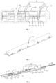
- the remote electrical tilt antenna 1000 includes a phase shifter 100 and a radiating element 200 connected to the phase shifter 100.
- a signal that needs to be radiated by the radiating element 200 is changed to a required phase by the phase shifter 100, and then is radiated by the radiating element 200.
- the radio frequency connection includes an electrical connection, a coupling connection, or the like.
- the phase shifter 100 is in a long-strip shape.
- the radiating element 200 is a radiating antenna. Further, there may be one or more independent phase shifters 100 in the remote electrical tilt antenna 1000, to meet practical requirements for users.
- the fastener 40 includes one or more first fasteners 41 disposed at intervals along an extension direction of the metal strip 20.
- the first fastener 41 is disposed on one side of the metal strip 20 and is perpendicular to a surface of the metal strip 20.
- there is one first fastener 41 and the first fastener 41 is fastened to one side on which the metal strip 20 is connected to the signal input terminal 21 and the signal output terminal 22.
- the signal input terminal 21 and the signal output terminal 22 pass through the first fastener 21 and are connected to the radiating element 200 via electricity or transmission.
- the first fastener 41 is fastened on one side on which the metal strip 20 is connected to the signal input terminal 21 and the signal output terminal 22, so that the first fastener 41 can exert a relatively good supporting effect on one end that is of the metal strip 20 and at which the signal input terminal 21 and the signal output terminal 22 are disposed, thereby avoiding an instability problem of the metal strip 20 resulted from a relatively strong force exerted to one side that is of the metal strip 20 and that is connected to the signal input terminal 21 and the signal output terminal 22.
- the signal input terminal 21 and the signal output terminal 22 may be disposed on two sides of the metal strip 20, and the first fastener 41 may be disposed on both sides of the metal strip 20. Therefore, the first fastener 41 disposed on both sides of the metal strip 20 supports the signal input terminal 21 or the signal output terminal 22 disposed on two sides of the metal strip 20 to ensure stability of the metal strip 20.
- the first fastener 41 is made of an insulation material, to avoid impacts of the first fastener 41 on signal transmission. It may be understood that, in another embodiment of the present invention, a part that is of the first fastener 41 and that is not in contact with the metal strip 20 may be made of a metal material, or a metal layer is disposed on an outer surface of the insulated first fastener 41, to exert no impact on signal transmission and achieve a good supporting effect.
- the first part 411 and the second part 412 of the first fastener 41 may be integrated; or the first part 411 and the second part 412 of the first fastener 41 are two separate parts, and the first part 411 and the second part 412 are fixedly connected, so that the metal strip 20 is clamped between the first part 411 and the second part 412.
- the first part 411 and the second part 412 may be fastened by welding or pasting, or in various ways easy to disassembly, such as buckling or fastening with a screw. It may be understood that there may be one or more first fasteners 41 in an extension direction of the metal strip 20.
- Ends that are of the first part 421 and the second part 422 and that are far away from the metal strip 20 abut against the inner wall of the cavity 10, to limit displacement of the metal strip 20 in a direction perpendicular to a surface of the metal strip 20, in other words, to limit movement in an up-down direction shown in the figure, thereby locating the metal strip 20 in the cavity 10 and stabilizing the metal strip 20 in the cavity 10.
- the phase shifter 100 may include only the first fastener 41 or the second fastener 42. Each position of the metal strip 20 may be stably supported and disposed in the cavity 10 by using the first fastener 41 or the second fastener 42.
- the cavity 10 is a long-strip-shaped tubular structure.
- the cavity 10 is a square tube. It may be understood that, in another embodiment of this application, the cavity 10 may also be a cylindrical tube or another polygonal tube.
- the cavity 10 includes a first inner wall 10a and a second inner wall 10b that are opposite to each other.
- the first inner wall 10a faces toward a first surface 20a of the metal strip 20.
- the second inner wall 10b faces toward the second surface 20b of the metal strip 20.
- a first groove 11 is provided on the first inner wall 10a, a second groove 12 opposite to the first groove 11 is provided on the second inner wall 10b, and an opening direction of the first groove 11 is opposite to that of the second groove 12. Furthermore, the first groove 11 and the second groove 12 each have a width the same as a thickness of the first fastener 41.
- the first groove 11 may be obtained by depressing a surface of the first inner wall 10a in a direction far away from the metal strip 20.
- two convex strips 13 are disposed on a surface of the first inner wall 10a in a direction toward the metal strip 20 and are spaced away from each other, and a gap between the two convex strips 13 is the first groove 11.
- the second groove 12 may be obtained by depressing a surface of the second inner wall 10b in a direction far away from the metal strip 20.
- two convex strips 13 are disposed on a surface of the second inner wall 10b in a direction toward the metal strip 20 and are spaced away from each other, and a gap between the two convex strips 13 is the second groove 12.
- the first fastener 41 drives the metal strip 20 to slide into the cavity 10 along the first groove 11 and the second groove 12, thereby making assembling a structure of the phase shifter 100 simple. It may be understood that, in another embodiment of the present invention, only the first groove 11 is provided on the first inner wall 10a, or only the second groove 12 is provided on the second inner wall 10b, to limit one side of the first fastener 41. This manner can also locate and stably dispose the metal strip 20 in the cavity 10.
- the first groove 11 and the second groove 12 coordinate with the first fastener 41 mainly to limit movement of the metal strip 20 in the cavity 10 that is parallel to the plane of the metal strip 20 and perpendicular to the extension direction of the metal strip 20, or limit movement of the metal strip 20 in a left-right direction as shown in FIG. 4 .
- the first groove may alternatively be provided at an end that is of the first part 411 of the first fastener 41 and that is far away from the metal strip 20, and the second groove may be provided at an end that is of the second part 412 of the first fastener 41 and that is far away from the metal strip 20.
- a first protrusion is disposed on the first inner wall 10a
- a second protrusion is disposed on the second inner wall 10b, the first protrusion is accommodated in the first groove
- the second protrusion is accommodated in the second groove, thereby locating the metal strip in the cavity.
- the sliding dielectric 30 is flat and is located on one side of a first surface 20a or a second surface 20b of the metal strip 20; or the sliding dielectric 30 is located on one side of the first surface 20a and one side of the second surface 20b.
- the sliding dielectric 30 may be disposed on one side or two opposite sides of the metal strip 20, so that phases are changed differently based on requirements when the sliding dielectric 30 is moved by a same distance.
- the sliding dielectric 30 when the sliding dielectric 30 is disposed on both the first surface 20a or that of the second surface 20b, the sliding dielectric 30 is moved by a same distance, and a dielectric constant of a dielectric changes greatly in the transmission section within the moved distance. That is, a phase changes greatly.
- the two sliding dielectrics 30 are fastened together by a buckle or a screw, so that the two sliding dielectrics 30 are synchronously movable to facilitate an operation.
- the sliding dielectric 30 located on any surface of the metal strip 20 may be a whole structure, or may be formed by splicing a plurality of divided structures.
- a length of the sliding dielectric 30 is less than that of the metal strip 20.
- phases of output signal terminals 22 located at two ends of the metal strip 20 are simultaneously changed.
- an area of the sliding dielectric 30 covering the metal strip 20 in a transmission section between the signal input terminal 21 and the first signal output terminal 221 enlarges, thereby increasing an equivalent dielectric constant of the dielectric in the transmission section.
- the sliding dielectric 30 includes a first section 30a, a second section 30b, and a connection section 30c connecting the first section 30a and the second section 30b.
- the first section 30a and the second section 30b are staggered in a direction perpendicular to the extension direction of the metal strip 20.
- the first section 30a, the second section 30b, and the connection section 30c are connected to form a Z-shaped structure.
- the metal strip 20 includes a first section 20a, a second section 20b, and a connection section 20c connecting the first section 20a and the second section 20b.
- the first section 20a and the second section 20b are staggered in the direction perpendicular to the extension direction of the metal strip 20.
- the first section 20a, the second section 20b, and the connection section 20c are connected to form a Z-shaped structure.
- the first section 30a of the sliding dielectric 30 is stacked on the first section 20a of the metal strip 20 and movable relative to the first section 30a.
- the second section 30b of the sliding dielectric 30 is stacked on the second section 20b of the metal strip and movable relative to the second section 30b of the sliding dielectric.
- second fasteners 42 There are two or more second fasteners 42. In the direction perpendicular to the extension direction of the metal strip 20, one of the second fasteners 42 and the first section 30a of the sliding dielectric are located on a same side of the second section 30b of the sliding dielectric, and the second fastener 42 is disposed in a sliding direction of the first section 30a of the sliding dielectric, to limit the stroke of the sliding dielectric relative to the metal strip 20.
- the second fastener 42 may be located on one side away from the second section 30b in a stroke direction of the first section 30a, or located on one side near the second section 30b in a stroke direction of the first section 30a.
- another second fastener 42 and the second section 30b of the sliding dielectric 30 are located on a same side of the first section 30a of the sliding dielectric 30, and the second fastener 42 is disposed in a sliding direction of the second section 30b of the sliding dielectric 30, to limit the stroke of the sliding dielectric 30 relative to the metal strip 20.
- the second fastener 42 may be located on one side away from the first section 30a in a stroke direction of the second section 30b, or located on one side near the first section 30a in a stroke direction of the second section 30b.
- the first section 30a of the sliding dielectric 30 includes an upper end face 31 and a lower end face 32 parallel to the upper end face 31.
- the second section 30b includes an upper end face 33 and a lower end face 34 parallel to the upper end face 33.
- the upper end faces of the first section 30a and the second section 30b are located on a same side of the lower end faces. In other words, when the upper end face 31 is located above the lower end face 32, the upper end face 33 is also located above the lower end face 34.
- One of the second fasteners 42 is disposed in the first section 20a of the metal strip 20, and an outer surface of the second fastener 42 is in contact with the lower end face 32 of the first section 30a of the sliding dielectric 30.
- the second fastener 42 is movable along the lower end face 32 of the first section 30a, and a moving interval thereof is between the connection section 30c and an end that is of the first section 30a and that is far away from the second section 30b.
- Another second fastener 42 is disposed in the second section 20b of the metal strip 20, and an outer surface of the second fastener 42 is in contact with the upper end face 33 of the second section 30b of the sliding dielectric 30.
- the second fastener 42 is movable along the upper end face 33 of the second section 30b, and a moving interval thereof is between the connection section 30c and an end that is of the second section 30b and that is far away from the first section 30a.
- phase shifter 100 when the sliding dielectric 30 is moved relative to the metal strip 20, a moving distance of the sliding dielectric 30 relative to the metal strip 20 is limited by the second fastener 42, so that the sliding dielectric 30 is prevented from being detached from a surface of the metal strip 20, and a problem that a phase cannot be adjusted is also avoided. That is, at least a partial overlap of the metal strip 20 and the sliding dielectric 30 in a direction perpendicular to the metal strip 20 is ensured, and a coverage area of the sliding dielectric 30 on the metal strip 20 is changed, to change a phase of an output signal.
- the second fastener 42 moved relative to the lower end face 32 of the first section 30a is moved to the connection section 30c and is blocked by the connection section 30c, so that the sliding dielectric 30 is prevented from becoming dispatched from the metal strip 20 due to further movement toward the first signal output terminal 221.
- the second fastener 42 is moved relative to the upper end face 33 of the second section 30b is moved to the connection section 30c and is blocked by the connection section 30c, so that the sliding dielectric 30 is prevented from becoming dispatched from the metal strip 20 due to further movement toward the fifth signal output terminal 225.
- the sliding dielectric 30 is provided with one or more conduits 32 disposed at intervals, the second fastener 42 is inserted into the conduit 32 and is movable along the conduit 32, and an extension direction of the conduit 32 is the same as that of the metal strip 20.
- the conduit 32 is provided on the sliding dielectric 30, to avoid impacts of the second fastener 42 on sliding of the sliding dielectric 30.
- the conduit 32 limits a stroke of the sliding dielectric 30 relative to the metal strip 20 to ensure that the sliding dielectric 30 can partially cover the metal strip 20 through movement, and ensure that phases of signals output by different signal output terminals 22 can be changed by moving the sliding dielectric 30.
- the sliding dielectric 30 may be in a tubular shape, and the sliding dielectric 30 is sleeved on the metal strip 20.
- the tubular sliding dielectric 30 is moved relative to the metal strip 20 to change a phase of an output signal.
- the tubular sliding dielectric may be a circular tube, a square tube, or a tube with a cross section of another shape.
- the phase shifter 100 further includes a sliding dielectric driving piece 60, which is connected to the sliding dielectric 30 to drive the sliding dielectric 30 to move relative to the metal strip 20.
- the sliding dielectric driving piece 60 is a driving rod. One end of the driving rod is connected to the sliding dielectric 30, and the other end is connected to various driving apparatuses such as a motor or a cylinder to drive the sliding dielectric 30 to be connected.
- a signal transmission line of the phase shifter 100 is the metal strip 20 formed by metal pieces such as metal wires or metal plates.
- the metal strip 20 is fastened and suspended by the fastener 40 in the cavity 10, requiring no metal strip to be disposed on a substrate, thereby reducing a signal energy loss of the substrate, decreasing heat generated due to the signal energy loss, and lowering requirements of the phase shifter 100 on heat dissipation and temperature resistance of an internal mechanical part.
Landscapes
- Engineering & Computer Science (AREA)
- Computer Networks & Wireless Communication (AREA)
- Waveguide Switches, Polarizers, And Phase Shifters (AREA)
Claims (6)
- Phasenschieber (100), umfassend einen Hohlraum (10), einen Metallstreifen (20), ein gleitendes Dielektrikum (30), ein Befestigungselement (40), einen Signaleingangsanschluss (2 1) und einen Signalausgangsanschluss (22), wobei der Metallstreifen mit dem Signaleingangsanschluss und dem Signalausgangsanschluss verbunden ist, der Metallstreifen einen Übertragungsabschnitt und einen mit dem Übertragungsabschnitt verbundenen Befestigungsabschnitt umfasst;das Befestigungselement mit dem Befestigungsabschnitt verbunden ist, um den Metallstreifen in dem Hohlraum zu befestigen, und der Übertragungsabschnitt in dem Hohlraum schwebend angeordnet ist;das gleitende Dielektrikum in dem Hohlraum angeordnet und relativ zum Übertragungsabschnitt des Metallstreifens beweglich ist;das Befestigungselement ein erstes Befestigungselement (41) und ein zweites Befestigungselement (42) umfasst, der Metallstreifen eine erste Oberfläche (20a) und eine der ersten Oberfläche gegenüberliegende zweite Oberfläche (20b) umfasst, und das erste Befestigungselement einen ersten Teil (411), der auf der ersten Oberfläche angeordnet ist, und einen zweiten Teil (412), der auf der zweiten Oberfläche angeordnet ist, umfasst; und beide Enden, die von dem ersten Teil des ersten Befestigungselements und dem zweiten Teil des ersten Befestigungselements sind und die von dem Metallstreifen entfernt sind, gegen eine Innenwand des Hohlraums anliegen;das zweite Befestigungselement sich auf derselben Seite wie das erste Befestigungselement befindet und vom ersten Befestigungselement beabstandet ist; und das zweite Befestigungselement einen ersten Teil (421) umfasst, der auf der ersten Oberfläche des Metallstreifens angeordnet ist, und einen zweiten Teil (422), der auf der zweiten Oberfläche angeordnet ist, und beide Enden, die von dem ersten Teil des zweiten Befestigungselements und des zweiten Teils des zweiten Befestigungselements sind, die von dem Metallstreifen weit entfernt sind, gegen eine Innenwand des Hohlraums anliegen;das zweite Befestigungselement mit einer Öffnung (423) bereitgestellt wird, die durch den ersten Teil des zweiten Befestigungselements und den zweiten Teil des zweiten Befestigungselements verläuft, eine Seitenwand des Hohlraums mit einem der Öffnung entsprechenden Durchgangsloch bereitgestellt wird und ein Begrenzungselement (50) durch das Durchgangsloch und die Öffnung verläuft,das gleitende Dielektrikum (30) flach ist und das gleitende Dielektrikum (30) sich auf einer Seite der ersten Oberfläche oder der zweiten Oberfläche des Metallstreifens (20) befindet, oder ein gleitendes Dielektrikum (30) sich auf einer Seite der ersten Oberfläche des Metallstreifens (20) und ein gleitendes Dielektrikum (30) sich auf einer Seite der zweiten Oberfläche des Metallstreifens (20) befindet,dadurch gekennzeichnet, dassein Kanal (32) auf dem gleitenden Dielektrikum (30) bereitgestellt wird, das zweite Befestigungselement (42) in den Kanal (32) eingefügt wird und entlang des Kanals (32) beweglich ist, und eine Erstreckungsrichtung des Kanals (32) die gleiche ist wie die des Metallstreifens (20).
- Phasenschieber nach Anspruch 1, wobei der Hohlraum eine erste Innenwand und eine zweite Innenwand umfasst, die einander gegenüberliegen, wobei die erste Innenwand einer ersten Oberfläche des Metallstreifens zugewandt ist und die zweite Innenwand einer zweiten Oberfläche des Metallstreifens zugewandt ist, wobei eine erste Nut an der ersten Innenwand bereitgestellt ist, ein Ende, das zum ersten Teil des ersten Befestigungselements gehört und weit vom Metallstreifen entfernt ist, in der ersten Nut untergebracht ist, und/oder eine zweite Nut an der zweiten Innenwand bereitgestellt ist und ein Ende, das zum zweiten Teil des ersten Befestigungselements gehört und weit vom Metallstreifen entfernt ist, in der zweiten Nut untergebracht ist.
- Phasenschieber nach Anspruch 1, wobei der Signaleingangsanschluss und der Signalausgangsanschluss auf einer gleichen Seite des Metallstreifens verteilt sind und der Signaleingangsanschluss und der Signalausgangsanschluss in einer Erweiterungsrichtung des Metallstreifens voneinander beabstandet sind; und das erste Befestigungselement an dem Metallstreifen befestigt ist, und das erste Befestigungselement, der Signaleingangsanschluss und der Signalausgangsanschluss sich auf einer gleichen Seite des Metallstreifens befinden.
- Phasenschieber nach Anspruch 1, wobei zwei vorgenannte gleitende Dielektrika befestigt und synchron beweglich sind.
- Phasenschieber nach Anspruch 1, wobei der Übertragungsabschnitt mit einer wellenförmigen Struktur bereitgestellt wird, die durch einen gebogenen Metalldraht gebildet wird.
- Elektrische Fernschwenkantenne, umfassend ein strahlendes Element und den Phasenschieber nach einem der Ansprüche 1 bis 5, wobei das strahlende Element mit dem Phasenschieber verbunden ist und ein von dem Phasenschieber übertragenes elektromagnetisches Wellensignal von dem strahlenden Element abgestrahlt wird.
Applications Claiming Priority (2)
| Application Number | Priority Date | Filing Date | Title |
|---|---|---|---|
| CN201810860216.3A CN110783666A (zh) | 2018-07-31 | 2018-07-31 | 移相器及电调天线 |
| PCT/CN2019/098116 WO2020024893A1 (zh) | 2018-07-31 | 2019-07-29 | 移相器及电调天线 |
Publications (3)
| Publication Number | Publication Date |
|---|---|
| EP3823089A1 EP3823089A1 (de) | 2021-05-19 |
| EP3823089A4 EP3823089A4 (de) | 2021-08-04 |
| EP3823089B1 true EP3823089B1 (de) | 2024-11-27 |
Family
ID=69230806
Family Applications (1)
| Application Number | Title | Priority Date | Filing Date |
|---|---|---|---|
| EP19843956.4A Active EP3823089B1 (de) | 2018-07-31 | 2019-07-29 | Phasenumschalter und elektrische schwenkantenne |
Country Status (4)
| Country | Link |
|---|---|
| US (1) | US11870157B2 (de) |
| EP (1) | EP3823089B1 (de) |
| CN (1) | CN110783666A (de) |
| WO (1) | WO2020024893A1 (de) |
Families Citing this family (10)
| Publication number | Priority date | Publication date | Assignee | Title |
|---|---|---|---|---|
| CN212162087U (zh) * | 2020-06-04 | 2020-12-15 | 京信通信技术(广州)有限公司 | 天线装置、移相馈电装置和移相器 |
| WO2022099502A1 (en) * | 2020-11-11 | 2022-05-19 | Nokia Shanghai Bell Co., Ltd. | Phase shifter and antenna device |
| CN116636081B (zh) * | 2020-12-29 | 2026-03-24 | 华为技术有限公司 | 悬置带线、移相器及基站 |
| EP4246709B1 (de) * | 2020-12-31 | 2025-09-03 | Huawei Technologies Co., Ltd. | Phasenschieber und elektrisch gesteuerte antenne |
| WO2022207077A1 (en) | 2021-03-30 | 2022-10-06 | Telefonaktiebolaget Lm Ericsson (Publ) | Mobile communication antenna |
| CN115842227A (zh) | 2021-09-22 | 2023-03-24 | 康普技术有限责任公司 | 移相器及其制造方法 |
| CN116995403A (zh) * | 2022-04-25 | 2023-11-03 | 京信通信技术(广州)有限公司 | 天线、馈电网络结构及金属带线安装组件 |
| CN116706543A (zh) * | 2023-05-29 | 2023-09-05 | 中信科移动通信技术股份有限公司 | 移相器及基站天线 |
| CN119905790A (zh) * | 2023-10-26 | 2025-04-29 | 华为技术有限公司 | 一种移相器、天线及通信基站 |
| CN119905791A (zh) * | 2023-10-28 | 2025-04-29 | 华为技术有限公司 | 移相器及基站天线 |
Citations (2)
| Publication number | Priority date | Publication date | Assignee | Title |
|---|---|---|---|---|
| WO2006130083A1 (en) * | 2005-05-31 | 2006-12-07 | Powerwave Technologies Sweden Ab | Beam adjusting device |
| SE528903C2 (sv) * | 2005-05-31 | 2007-03-13 | Powerwave Technologies Sweden | Anordning för loboinställning |
Family Cites Families (11)
| Publication number | Priority date | Publication date | Assignee | Title |
|---|---|---|---|---|
| CN201369380Y (zh) * | 2009-02-13 | 2009-12-23 | 广东通宇通讯设备有限公司 | 天线用低损耗功分器 |
| CN102570033A (zh) * | 2011-11-16 | 2012-07-11 | 广州杰赛科技股份有限公司 | 电调天线馈电模块 |
| CN203787537U (zh) * | 2014-03-27 | 2014-08-20 | 华为技术有限公司 | 一种电调天线移相器 |
| CN104466405A (zh) * | 2014-11-11 | 2015-03-25 | 李梓萌 | 一种阵列天线可调移相装置 |
| CN105990633A (zh) * | 2015-01-29 | 2016-10-05 | 安弗施无线射频系统(上海)有限公司 | 传输线、传输装置以及移相设备 |
| CN106921011B (zh) * | 2015-12-28 | 2019-07-19 | 西安华为技术有限公司 | 一种移相器及天线 |
| CN205452488U (zh) * | 2015-12-31 | 2016-08-10 | 广东晖速通信技术股份有限公司 | 一种高频五口移相器 |
| JP6736948B2 (ja) * | 2016-04-04 | 2020-08-05 | 日立金属株式会社 | 移相器及びこれを備えたアンテナ装置 |
| WO2018120618A1 (zh) * | 2016-12-27 | 2018-07-05 | 深圳国人通信股份有限公司 | 一种小型化单步式移相器 |
| CN206789668U (zh) * | 2017-06-19 | 2017-12-22 | 京信通信系统(中国)有限公司 | 一种带射频连接器的移相器及天线 |
| CN108232377B (zh) * | 2017-12-22 | 2024-06-18 | 广东盛路通信科技股份有限公司 | 超宽带690-960MHz移相器 |
-
2018
- 2018-07-31 CN CN201810860216.3A patent/CN110783666A/zh active Pending
-
2019
- 2019-07-29 WO PCT/CN2019/098116 patent/WO2020024893A1/zh not_active Ceased
- 2019-07-29 EP EP19843956.4A patent/EP3823089B1/de active Active
-
2021
- 2021-01-28 US US17/161,550 patent/US11870157B2/en active Active
Patent Citations (2)
| Publication number | Priority date | Publication date | Assignee | Title |
|---|---|---|---|---|
| WO2006130083A1 (en) * | 2005-05-31 | 2006-12-07 | Powerwave Technologies Sweden Ab | Beam adjusting device |
| SE528903C2 (sv) * | 2005-05-31 | 2007-03-13 | Powerwave Technologies Sweden | Anordning för loboinställning |
Also Published As
| Publication number | Publication date |
|---|---|
| EP3823089A4 (de) | 2021-08-04 |
| US11870157B2 (en) | 2024-01-09 |
| US20210151881A1 (en) | 2021-05-20 |
| WO2020024893A1 (zh) | 2020-02-06 |
| EP3823089A1 (de) | 2021-05-19 |
| CN110783666A (zh) | 2020-02-11 |
Similar Documents
| Publication | Publication Date | Title |
|---|---|---|
| EP3823089B1 (de) | Phasenumschalter und elektrische schwenkantenne | |
| EP3289635B1 (de) | Antennen mit einer anordnung aus zwei strahlungselementen und leistungsteilern für drahtlose elektronische vorrichtungen | |
| EP3220472B1 (de) | Einstellbare phasenverschiebungsvorrichtung für eine gruppenantenne und antenne | |
| CN209133655U (zh) | 一种移相器及基站天线 | |
| JP4736658B2 (ja) | 漏れ波アンテナ | |
| EP2879235B1 (de) | Modul für phasenverschiebungseinheit, herstellungsverfahren dafür, phasenverschiebungsvorrichtung und antenne | |
| CN1547788B (zh) | 带有集成的移相器的可调整的天线馈送网络 | |
| US20140035792A1 (en) | Microstrip-Fed Crossed Dipole Antenna | |
| WO2016074593A1 (zh) | 一种用于基站天线的反射板以及基站天线阵列结构 | |
| US20070040758A1 (en) | Dipole antenna | |
| CN103066381A (zh) | 天线 | |
| JP5288330B2 (ja) | 平面アレーアンテナ | |
| US20250210876A1 (en) | Metamaterial-enabled beam scanning antenna | |
| González et al. | Millimeter-wave beam-steering focal plane arrays with microfluidically switched feed networks | |
| US20090033438A1 (en) | Adjustable Phase Shifter For Antenna | |
| KR101255444B1 (ko) | 배열 안테나에 사용되는 위상 천이기 | |
| CN116529951A (zh) | 天线及基站 | |
| CN220963750U (zh) | 一种天线、天线单元以及通信设备 | |
| JP4422657B2 (ja) | アンテナ装置 | |
| WO2022141564A1 (zh) | 电子器件和天线 | |
| JP6565838B2 (ja) | 導波管型可変移相器および導波管スロットアレーアンテナ装置 | |
| JP2009159203A (ja) | 誘電体レンズ付きアンテナ | |
| GB2426635A (en) | Phase shifting arrangement | |
| JP6331168B2 (ja) | アンテナ装置 | |
| CN116799493B (zh) | 一种天线、天线单元以及通信设备 |
Legal Events
| Date | Code | Title | Description |
|---|---|---|---|
| STAA | Information on the status of an ep patent application or granted ep patent |
Free format text: STATUS: THE INTERNATIONAL PUBLICATION HAS BEEN MADE |
|
| PUAI | Public reference made under article 153(3) epc to a published international application that has entered the european phase |
Free format text: ORIGINAL CODE: 0009012 |
|
| STAA | Information on the status of an ep patent application or granted ep patent |
Free format text: STATUS: REQUEST FOR EXAMINATION WAS MADE |
|
| 17P | Request for examination filed |
Effective date: 20210210 |
|
| AK | Designated contracting states |
Kind code of ref document: A1 Designated state(s): AL AT BE BG CH CY CZ DE DK EE ES FI FR GB GR HR HU IE IS IT LI LT LU LV MC MK MT NL NO PL PT RO RS SE SI SK SM TR |
|
| A4 | Supplementary search report drawn up and despatched |
Effective date: 20210702 |
|
| RIC1 | Information provided on ipc code assigned before grant |
Ipc: H01P 1/18 20060101AFI20210628BHEP |
|
| DAV | Request for validation of the european patent (deleted) | ||
| DAX | Request for extension of the european patent (deleted) | ||
| STAA | Information on the status of an ep patent application or granted ep patent |
Free format text: STATUS: EXAMINATION IS IN PROGRESS |
|
| 17Q | First examination report despatched |
Effective date: 20230605 |
|
| GRAP | Despatch of communication of intention to grant a patent |
Free format text: ORIGINAL CODE: EPIDOSNIGR1 |
|
| STAA | Information on the status of an ep patent application or granted ep patent |
Free format text: STATUS: GRANT OF PATENT IS INTENDED |
|
| RIC1 | Information provided on ipc code assigned before grant |
Ipc: H01Q 3/32 20060101ALI20240624BHEP Ipc: H01Q 1/24 20060101ALI20240624BHEP Ipc: H01P 1/18 20060101AFI20240624BHEP |
|
| INTG | Intention to grant announced |
Effective date: 20240726 |
|
| GRAS | Grant fee paid |
Free format text: ORIGINAL CODE: EPIDOSNIGR3 |
|
| GRAA | (expected) grant |
Free format text: ORIGINAL CODE: 0009210 |
|
| STAA | Information on the status of an ep patent application or granted ep patent |
Free format text: STATUS: THE PATENT HAS BEEN GRANTED |
|
| AK | Designated contracting states |
Kind code of ref document: B1 Designated state(s): AL AT BE BG CH CY CZ DE DK EE ES FI FR GB GR HR HU IE IS IT LI LT LU LV MC MK MT NL NO PL PT RO RS SE SI SK SM TR |
|
| REG | Reference to a national code |
Ref country code: GB Ref legal event code: FG4D |
|
| REG | Reference to a national code |
Ref country code: CH Ref legal event code: EP |
|
| REG | Reference to a national code |
Ref country code: DE Ref legal event code: R096 Ref document number: 602019062699 Country of ref document: DE |
|
| REG | Reference to a national code |
Ref country code: IE Ref legal event code: FG4D |
|
| REG | Reference to a national code |
Ref country code: LT Ref legal event code: MG9D |
|
| REG | Reference to a national code |
Ref country code: NL Ref legal event code: MP Effective date: 20241127 |
|
| PG25 | Lapsed in a contracting state [announced via postgrant information from national office to epo] |
Ref country code: HR Free format text: LAPSE BECAUSE OF FAILURE TO SUBMIT A TRANSLATION OF THE DESCRIPTION OR TO PAY THE FEE WITHIN THE PRESCRIBED TIME-LIMIT Effective date: 20241127 Ref country code: IS Free format text: LAPSE BECAUSE OF FAILURE TO SUBMIT A TRANSLATION OF THE DESCRIPTION OR TO PAY THE FEE WITHIN THE PRESCRIBED TIME-LIMIT Effective date: 20250327 Ref country code: PT Free format text: LAPSE BECAUSE OF FAILURE TO SUBMIT A TRANSLATION OF THE DESCRIPTION OR TO PAY THE FEE WITHIN THE PRESCRIBED TIME-LIMIT Effective date: 20250327 |
|
| PG25 | Lapsed in a contracting state [announced via postgrant information from national office to epo] |
Ref country code: FI Free format text: LAPSE BECAUSE OF FAILURE TO SUBMIT A TRANSLATION OF THE DESCRIPTION OR TO PAY THE FEE WITHIN THE PRESCRIBED TIME-LIMIT Effective date: 20241127 Ref country code: NL Free format text: LAPSE BECAUSE OF FAILURE TO SUBMIT A TRANSLATION OF THE DESCRIPTION OR TO PAY THE FEE WITHIN THE PRESCRIBED TIME-LIMIT Effective date: 20241127 |
|
| REG | Reference to a national code |
Ref country code: AT Ref legal event code: MK05 Ref document number: 1746639 Country of ref document: AT Kind code of ref document: T Effective date: 20241127 |
|
| PG25 | Lapsed in a contracting state [announced via postgrant information from national office to epo] |
Ref country code: BG Free format text: LAPSE BECAUSE OF FAILURE TO SUBMIT A TRANSLATION OF THE DESCRIPTION OR TO PAY THE FEE WITHIN THE PRESCRIBED TIME-LIMIT Effective date: 20241127 |
|
| PG25 | Lapsed in a contracting state [announced via postgrant information from national office to epo] |
Ref country code: ES Free format text: LAPSE BECAUSE OF FAILURE TO SUBMIT A TRANSLATION OF THE DESCRIPTION OR TO PAY THE FEE WITHIN THE PRESCRIBED TIME-LIMIT Effective date: 20241127 |
|
| PG25 | Lapsed in a contracting state [announced via postgrant information from national office to epo] |
Ref country code: NO Free format text: LAPSE BECAUSE OF FAILURE TO SUBMIT A TRANSLATION OF THE DESCRIPTION OR TO PAY THE FEE WITHIN THE PRESCRIBED TIME-LIMIT Effective date: 20250227 |
|
| PG25 | Lapsed in a contracting state [announced via postgrant information from national office to epo] |
Ref country code: LV Free format text: LAPSE BECAUSE OF FAILURE TO SUBMIT A TRANSLATION OF THE DESCRIPTION OR TO PAY THE FEE WITHIN THE PRESCRIBED TIME-LIMIT Effective date: 20241127 Ref country code: GR Free format text: LAPSE BECAUSE OF FAILURE TO SUBMIT A TRANSLATION OF THE DESCRIPTION OR TO PAY THE FEE WITHIN THE PRESCRIBED TIME-LIMIT Effective date: 20250228 Ref country code: AT Free format text: LAPSE BECAUSE OF FAILURE TO SUBMIT A TRANSLATION OF THE DESCRIPTION OR TO PAY THE FEE WITHIN THE PRESCRIBED TIME-LIMIT Effective date: 20241127 |
|
| PG25 | Lapsed in a contracting state [announced via postgrant information from national office to epo] |
Ref country code: PL Free format text: LAPSE BECAUSE OF FAILURE TO SUBMIT A TRANSLATION OF THE DESCRIPTION OR TO PAY THE FEE WITHIN THE PRESCRIBED TIME-LIMIT Effective date: 20241127 |
|
| PG25 | Lapsed in a contracting state [announced via postgrant information from national office to epo] |
Ref country code: RS Free format text: LAPSE BECAUSE OF FAILURE TO SUBMIT A TRANSLATION OF THE DESCRIPTION OR TO PAY THE FEE WITHIN THE PRESCRIBED TIME-LIMIT Effective date: 20250227 |
|
| PG25 | Lapsed in a contracting state [announced via postgrant information from national office to epo] |
Ref country code: SM Free format text: LAPSE BECAUSE OF FAILURE TO SUBMIT A TRANSLATION OF THE DESCRIPTION OR TO PAY THE FEE WITHIN THE PRESCRIBED TIME-LIMIT Effective date: 20241127 |
|
| PG25 | Lapsed in a contracting state [announced via postgrant information from national office to epo] |
Ref country code: DK Free format text: LAPSE BECAUSE OF FAILURE TO SUBMIT A TRANSLATION OF THE DESCRIPTION OR TO PAY THE FEE WITHIN THE PRESCRIBED TIME-LIMIT Effective date: 20241127 |
|
| PG25 | Lapsed in a contracting state [announced via postgrant information from national office to epo] |
Ref country code: EE Free format text: LAPSE BECAUSE OF FAILURE TO SUBMIT A TRANSLATION OF THE DESCRIPTION OR TO PAY THE FEE WITHIN THE PRESCRIBED TIME-LIMIT Effective date: 20241127 |
|
| PG25 | Lapsed in a contracting state [announced via postgrant information from national office to epo] |
Ref country code: RO Free format text: LAPSE BECAUSE OF FAILURE TO SUBMIT A TRANSLATION OF THE DESCRIPTION OR TO PAY THE FEE WITHIN THE PRESCRIBED TIME-LIMIT Effective date: 20241127 |
|
| PG25 | Lapsed in a contracting state [announced via postgrant information from national office to epo] |
Ref country code: SK Free format text: LAPSE BECAUSE OF FAILURE TO SUBMIT A TRANSLATION OF THE DESCRIPTION OR TO PAY THE FEE WITHIN THE PRESCRIBED TIME-LIMIT Effective date: 20241127 |
|
| PG25 | Lapsed in a contracting state [announced via postgrant information from national office to epo] |
Ref country code: CZ Free format text: LAPSE BECAUSE OF FAILURE TO SUBMIT A TRANSLATION OF THE DESCRIPTION OR TO PAY THE FEE WITHIN THE PRESCRIBED TIME-LIMIT Effective date: 20241127 |
|
| PG25 | Lapsed in a contracting state [announced via postgrant information from national office to epo] |
Ref country code: IT Free format text: LAPSE BECAUSE OF FAILURE TO SUBMIT A TRANSLATION OF THE DESCRIPTION OR TO PAY THE FEE WITHIN THE PRESCRIBED TIME-LIMIT Effective date: 20241127 |
|
| REG | Reference to a national code |
Ref country code: DE Ref legal event code: R097 Ref document number: 602019062699 Country of ref document: DE |
|
| PG25 | Lapsed in a contracting state [announced via postgrant information from national office to epo] |
Ref country code: SE Free format text: LAPSE BECAUSE OF FAILURE TO SUBMIT A TRANSLATION OF THE DESCRIPTION OR TO PAY THE FEE WITHIN THE PRESCRIBED TIME-LIMIT Effective date: 20241127 |
|
| PLBE | No opposition filed within time limit |
Free format text: ORIGINAL CODE: 0009261 |
|
| STAA | Information on the status of an ep patent application or granted ep patent |
Free format text: STATUS: NO OPPOSITION FILED WITHIN TIME LIMIT |
|
| REG | Reference to a national code |
Ref country code: CH Ref legal event code: L10 Free format text: ST27 STATUS EVENT CODE: U-0-0-L10-L00 (AS PROVIDED BY THE NATIONAL OFFICE) Effective date: 20251008 |
|
| PGFP | Annual fee paid to national office [announced via postgrant information from national office to epo] |
Ref country code: DE Payment date: 20250604 Year of fee payment: 7 |
|
| 26N | No opposition filed |
Effective date: 20250828 |
|
| REG | Reference to a national code |
Ref country code: CH Ref legal event code: H13 Free format text: ST27 STATUS EVENT CODE: U-0-0-H10-H13 (AS PROVIDED BY THE NATIONAL OFFICE) Effective date: 20260224 |
|
| PG25 | Lapsed in a contracting state [announced via postgrant information from national office to epo] |
Ref country code: LU Free format text: LAPSE BECAUSE OF NON-PAYMENT OF DUE FEES Effective date: 20250729 |
|
| GBPC | Gb: european patent ceased through non-payment of renewal fee |
Effective date: 20250729 |
|
| REG | Reference to a national code |
Ref country code: BE Ref legal event code: MM Effective date: 20250731 |
|
| PG25 | Lapsed in a contracting state [announced via postgrant information from national office to epo] |
Ref country code: GB Free format text: LAPSE BECAUSE OF NON-PAYMENT OF DUE FEES Effective date: 20250729 |
|
| PG25 | Lapsed in a contracting state [announced via postgrant information from national office to epo] |
Ref country code: BE Free format text: LAPSE BECAUSE OF NON-PAYMENT OF DUE FEES Effective date: 20250731 |
|
| PG25 | Lapsed in a contracting state [announced via postgrant information from national office to epo] |
Ref country code: FR Free format text: LAPSE BECAUSE OF NON-PAYMENT OF DUE FEES Effective date: 20250731 |