EP3821137B1 - Kolben-zylinder-einheit für eine arbeitsmaschine - Google Patents
Kolben-zylinder-einheit für eine arbeitsmaschine Download PDFInfo
- Publication number
- EP3821137B1 EP3821137B1 EP19770019.8A EP19770019A EP3821137B1 EP 3821137 B1 EP3821137 B1 EP 3821137B1 EP 19770019 A EP19770019 A EP 19770019A EP 3821137 B1 EP3821137 B1 EP 3821137B1
- Authority
- EP
- European Patent Office
- Prior art keywords
- cylinder
- piston
- plug
- bearing
- sensor unit
- Prior art date
- Legal status (The legal status is an assumption and is not a legal conclusion. Google has not performed a legal analysis and makes no representation as to the accuracy of the status listed.)
- Active
Links
Images


Classifications
-
- F—MECHANICAL ENGINEERING; LIGHTING; HEATING; WEAPONS; BLASTING
- F15—FLUID-PRESSURE ACTUATORS; HYDRAULICS OR PNEUMATICS IN GENERAL
- F15B—SYSTEMS ACTING BY MEANS OF FLUIDS IN GENERAL; FLUID-PRESSURE ACTUATORS, e.g. SERVOMOTORS; DETAILS OF FLUID-PRESSURE SYSTEMS, NOT OTHERWISE PROVIDED FOR
- F15B15/00—Fluid-actuated devices for displacing a member from one position to another; Gearing associated therewith
- F15B15/08—Characterised by the construction of the motor unit
- F15B15/14—Characterised by the construction of the motor unit of the straight-cylinder type
- F15B15/1423—Component parts; Constructional details
- F15B15/1457—Piston rods
- F15B15/1461—Piston rod sealings
-
- F—MECHANICAL ENGINEERING; LIGHTING; HEATING; WEAPONS; BLASTING
- F15—FLUID-PRESSURE ACTUATORS; HYDRAULICS OR PNEUMATICS IN GENERAL
- F15B—SYSTEMS ACTING BY MEANS OF FLUIDS IN GENERAL; FLUID-PRESSURE ACTUATORS, e.g. SERVOMOTORS; DETAILS OF FLUID-PRESSURE SYSTEMS, NOT OTHERWISE PROVIDED FOR
- F15B15/00—Fluid-actuated devices for displacing a member from one position to another; Gearing associated therewith
- F15B15/08—Characterised by the construction of the motor unit
- F15B15/14—Characterised by the construction of the motor unit of the straight-cylinder type
- F15B15/1423—Component parts; Constructional details
- F15B15/1433—End caps
-
- F—MECHANICAL ENGINEERING; LIGHTING; HEATING; WEAPONS; BLASTING
- F15—FLUID-PRESSURE ACTUATORS; HYDRAULICS OR PNEUMATICS IN GENERAL
- F15B—SYSTEMS ACTING BY MEANS OF FLUIDS IN GENERAL; FLUID-PRESSURE ACTUATORS, e.g. SERVOMOTORS; DETAILS OF FLUID-PRESSURE SYSTEMS, NOT OTHERWISE PROVIDED FOR
- F15B15/00—Fluid-actuated devices for displacing a member from one position to another; Gearing associated therewith
- F15B15/08—Characterised by the construction of the motor unit
- F15B15/14—Characterised by the construction of the motor unit of the straight-cylinder type
- F15B15/1423—Component parts; Constructional details
- F15B15/1438—Cylinder to end cap assemblies
Definitions
- the invention relates to a piston-cylinder unit for a working machine with at least one cylinder and a piston rod displaceably mounted therein, wherein at least one piston rod bearing is provided in the region of the cylinder opening for supporting or guiding the piston rod.
- Piston-cylinder units for hydraulic or pneumatic cylinders are well known.
- a bearing or guide is provided in the area where the piston rod exits the cylinder housing, for example, in the form of a bearing bush inserted into the cylinder housing.
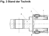
- Figures 1-3 Different designs of generic cylinders with piston rod bearings are shown.
- Figure 1 shows a cross-section through the cylinder housing 1 in the area of the cylinder opening, into which a bearing bush 3 is inserted.
- the bearing bush is provided with an external thread 3a in order to screw the bearing bush 3 into the opening area of the cylinder 1, which is provided with an internal thread.
- bearing bushes 5 see Figure 2 ), which are simply inserted into the cylinder opening and fixed using separate 5-edge retaining screws 6.
- CN104315149A shows a piston-cylinder unit according to the preamble of claim 1.
- the idea of the present invention is to show an alternative solution for a piston-cylinder unit or piston rod bearing, which allows a simple and better integration of any component, in particular a corresponding sensor unit.
- the piston rod bearing used is designed to be at least two-part, wherein the piston rod bearing consists of at least one plug-in part that can be inserted or is inserted into the cylinder opening, and at least one screw-threaded part that can be screwed or is screwed to the cylinder wall and serves to fix the plug-in part within the cylinder.
- the plug-in part comprises an integral sensor unit.
- the plug-in part is simply pushed or inserted into the cylinder opening.
- the screw part has a matching thread and engages with a complementary thread in the cylinder housing.
- the screw part has an external thread that interacts with an internal thread of the cylinder in the area of the cylinder opening. Screwing in causes the screw part to move axially against the plug-in part, thus ensuring sufficient fixation of the plug-in part within the cylinder opening.
- the two-part construction of the bearing bush ensures that a sensor unit is housed in the plug-in part.
- the piston rod bearing is designed as a two-part bearing bush.
- the outer circumference of the bearing bush is formed by the assembled bearing parts, while the inner circumference, which accommodates the piston rod, is formed by only one of the bearing parts.
- a preferred embodiment of the screw part is a threaded ring with an external thread.
- the plug-in part particularly preferably provides a cylindrical projection onto which the threaded ring is placed. When screwed in, the threaded ring exerts a force acting in the axial direction on the plug-in part, thereby pressing it into the cylinder opening.
- the plug-in part comprises a corresponding stop surface for the screw part or the threaded ring.
- the plug-in part can be provided with an axial bore for the exit of one or more connecting cables of the sensor unit. These can then exit at the front in the area of the cylinder opening.
- the piston-cylinder unit in question is preferably a hydraulic cylinder or pneumatic cylinder.
- the present invention also relates to a work machine with a piston-cylinder unit according to the invention. Consequently, the same advantages and properties as already explained above with reference to the piston-cylinder unit according to the invention result for the work machine. For this reason, a repetitive description is omitted.
- the work machine can be a crane or an earthmoving machine or other construction machine.
- Figure 4 shows a first embodiment of the piston-cylinder unit according to the invention.
- This comprises the cylinder housing 10 and a piston rod 20 extending from the cylinder housing 10 and mounted for axial displacement.
- the two-part bearing bush 30 according to the invention is inserted into the cylinder housing 10.
- the bearing bush 30 is composed of a first bearing part 31 in the form of the threaded ring 31 and the second bearing part in the form of the plug-in bush 32.
- the plug-in bushing 32 is inserted into the cylinder opening during cylinder assembly, in particular until the stop edge 32a abuts a stop surface of the cylinder housing 10 and prevents further penetration of the bearing bushing 30 into the cylinder 10.
- An integral component of the plug-in bushing 32 is the sensor unit 40, which is inserted into a cavity provided for this purpose in the bearing part 32. Any connecting lines of the sensor unit 40 can be led out of the cylinder housing 10 at the end face of the bearing part 32 via at least one axial bore 41.
- the plug-in bushing 32 provides a cylindrical projection 32c, onto which the threaded ring 31 can be coaxially mounted.
- the threaded ring 31 itself comprises at least one external thread 31a, which engages with a complementary internal thread of the cylinder housing 10.
- bearing bush 30 An alternative embodiment of the bearing bush 30 is shown in the illustration according to Figure 5 shown.
- the plug-in bush 32' also includes an integrated sensor unit 40'.
- this unit is screwed with its connecting lines 41' into a radial bore 50 of the plug-in bush 32', so that all sensor lines 41' also extend radially out of the cylinder housing 10.
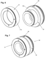
- FIGs 6 and 7 show again perspective views of the bearing bush 30 according to the invention according to the embodiment of Figure 4
- the above images show the disassembled bearing bush with the plug-in part 32 and the threaded ring 31.
- Figure 7 shows the assembled bearing bush 30.
Landscapes
- Engineering & Computer Science (AREA)
- Physics & Mathematics (AREA)
- Fluid Mechanics (AREA)
- Mechanical Engineering (AREA)
- General Engineering & Computer Science (AREA)
- Actuator (AREA)
Description
- Die Erfindung betrifft eine Kolben-Zylinder-Einheit für eine Arbeitsmaschine mit wenigstens einem Zylinder und einer darin verschieblich gelagerten Kolbenstange, wobei im Bereich der Zylinderöffnung wenigstens ein Kolbenstangenlager zur Lagerung bzw. Führung der Kolbenstange vorgesehen ist.
- Kolben-Zylinder-Einheiten für Hydraulik- bzw. Pneumatikzylinder sind hinreichend bekannt. Im Bereich des Austritts der Kolbenstange aus dem Zylindergehäuse wird ein Lager bzw. eine Führung vorgesehen, bspw. in Form einer in das Zylindergehäuse eingesetzten Lagerbuchse. In den
Figuren 1-3 sind unterschiedliche Ausführungsformen gattungsgemäßer Zylinder mit Kolbenstangenlager dargestellt.Figur 1 zeigt einen Querschnitt durch das Zylindergehäuse 1 im Bereich der Zylinderöffnung, in diese eine Lagerbuchse 3 eingesetzt ist. Die Lagerbuchse ist mit einem Außengewinde 3a versehen, um die Lagerbuchse 3 in den mit einem Innengewinde versehenen Öffnungsbereich des Zylinders 1 einzuschrauben. Als Alternative sind Lagerbuchsen 5 (s.Figur 2 ) bekannt, die lediglich in die Zylinderöffnung eingeschoben werden und über separate 5-kant Halteschrauben 6 fixiert werden. -
CN104315149A zeigt eine Kolben-Zylinder-Einheit gemäß dem Oberbegriff des Anspruchs 1. - Anwendungsabhängig besteht der Wunsch nach einer in den Zylinder integrierten Sensorik, sei es zur Druck- oder auch Längen- bzw. Positionsmessung. Gewünscht ist eine direkte Integration der Sensoreinheit in die Lagerbuchse, notwendige Energie- und Signalleitungen der Sensoreinheit müssen dann über Kanäle der Lagerbuchse bzw. des Zylindergehäuses herausgeführt werden. Problematisch ist dies insbesondere bei der Ausführungsform gemäß
Figur 1 , denn die mit einem Außengewinde 3a versehene Buchse 3 bietet weder ausreichend Platz für die Sensoreinheit noch entsprechende Leitungskanäle. Aus diesem Grund wird die Lagerbuchse wie inFigur 3 gezeigt, in Axialrichtung verlängert. Durch das Herausragen der Lagerbuchse 7 aus der Zylinderöffnung wird jedoch nachteilig der Kolbenhub verkürzt. - Die Idee der vorliegenden Erfindung besteht nun darin, eine alternative Lösung für eine Kolben-Zylinder-Einheit bzw. Kolbenstangenlagerung aufzuzeigen, die eine einfache und bessere Integration einer beliebigen Komponente, insbesondere einer entsprechenden Sensoreinheit erlaubt.
- Gelöst wird diese Aufgabe durch eine Kolben-Zylinder-Einheit gemäß den Merkmalen des Anspruchs 1. Vorteilhafte Ausgestaltungen der Kolben-Zylinder-Einheit sind Gegenstand der abhängigen Ansprüche.
- Erfindungsgemäß wird hierbei vorgeschlagen, das eingesetzte Kolbenstangenlager mindestens zweiteilig auszuführen, wobei das Kolbenstangenlager aus wenigstens einem Steckteil besteht, das in die Zylinderöffnung einsetzbar bzw. eingesetzt ist, und wenigstens ein Schraubteil mit Gewinde umfasst, das mit der Zylinderwand verschraubbar bzw. verschraubt ist und zur Fixierung des Steckteils innerhalb des Zylinders dient. Erfindungsgemäß umfasst das Steckteil eine integrale Sensoreinheit.
- Das Steckteil ist lediglich in die Zylinderöffnung eingeschoben bzw. eingesetzt. Das Schaubteil ist mit passendem Gewinde ausgeführt und greift in ein komplementäres Gewinde des Zylindergehäuses ein. Bspw. sieht das Schraubteil ein Aussengewinde vor, das mit einem Innengewinde des Zylinders im Bereich der Zylinderöffnung zusammenwirkt. Durch das Einschrauben wird das Schraubteil in Axialrichtung gegen das Steckteil bewegt und sorgt somit für eine ausreichende Fixierung des Steckteils innerhalb der Zylinderöffnung.
- Der zweiteilige Aufbau der Lagerbüchse sorgt dafür, dass eine Sensoreinheit in dem Steckteil untergebracht wird.
- Gemäß bevorzugter Ausführung ist das Kolbenstangenlager als zweiteilige Lagerbuchse ausgeführt. Vorzugsweise wird der Aussenumfang der Lagerbuchse durch die zusammengesetzten Lagerteile gebildet, während der Innenumfang, der die Kolbenstange aufnimmt, lediglich durch eines der Lagerteile geformt wird.
- Bevorzugt wird eine Ausführung des Schraubteils als Gewindering mit Aussengewinde. Ferner sieht das Steckteil besonders bevorzugt einen zylindrischen Vorsprung vor, auf diesen der Gewindering aufgesetzt ist. Beim Einschrauben bringt der Gewindering eine in Axialrichtung wirkende Kraft auf das Steckteil auf, wodurch dieses in die Zylinderöffnung hinein gedrückt wird. Insbesondere umfasst das Steckteil eine entsprechende Anschlagsfläche für das Schraubteil bzw. den Gewindering. Denkbar ist eine Ausführung des Steckteils mit einem zylindrischen Vorsprung zur Aufnahme des Gewinderings und einer stufenartigen Durchmesservergrößerung auf den Aussendurchmesser des Lagers als Anschlagsfläche.
- Für die Ausleitung entsprechender Anschlussleitungen der integralen Sensoreinheit besteht die Möglichkeit, wenigstens eine radiale Bohrung in dem Steckteil vorzusehen.
- Durch die Integration der Sensoreinheit in das Steckteil stören entsprechende Gewindeausführungen nicht bei der Platzierung der Radialbohrung, denn diese sind stattdessen am Schraubteil der Lagerbuchse vorgesehen. Denkbar ist es auch, dass innerhalb der Radialbohrung die gesamte Sensoreinheit inklusive Anschlussleitungen einschraubbar ist. Als Anschlussleitungen werden sowohl Signalleitungen als auch Energieversorgungsleitungen verstanden.
- Alternativ kann vorgesehen sein, dass das Steckteil, eine Axialbohrung zur Ausleitung ein oder mehrerer Anschlussleitungen der Sensoreinheit umfasst. Diese können dann stirnseitig im Bereich der Zylinderöffnung austreten.
- Bei der beanspruchten Kolben-Zylinder-Einheit handelt es sich vorzugsweise um einen Hydraulikzylinder oder auch Pneumatikzylinder.
- Neben der Zylindereinheit betrifft die vorliegende Erfindung auch eine Arbeitsmaschine mit einer erfindungsgemäßen Kolben-Zylinder-Einheit. Demzufolge ergeben sich für die Arbeitsmaschine dieselben Vorteile und Eigenschaften, wie sie bereits vorstehend anhand der erfindungsgemäßen Kolbenzylindereinheit erläutert wurden. Auf eine wiederholende Beschreibung wird aus diesem Grund verzichtet.
- Die Arbeitsmaschine kann ein Kran oder eine Erdbewegungsmaschine bzw. sonstige Baumaschine sein.
- Weitere Vorteile und Eigenschaften der Erfindung sollen nachfolgend anhand der in den Zeichnungen dargestellten Ausführungsbeispiele näher erläutert werden. Es zeigen:
- Figuren 1-3:
- unterschiedliche Varianten einer Kolben-Zylinder-Einheit gemäß dem Stand der Technik,
- Figur 4:
- eine Schnittdarstellung einer erfindungsgemäßen Kolben-Zylinder-Einheit im Bereich der Lagerbuchse,
- Figur 5:
- eine Schnittdarstellung einer weiteren Ausführungsform der erfindungsgemäßen Kolben-Zylinder-Einheit im Bereich der Lagerbuchse und
- Figur 6:
- perspektivische Darstellungen der zweiteiligen Lagerbuchse gemäß der Ausführungsform aus
Figur 5 . -
Figur 4 zeigt ein erstes Ausführungsbeispiel der erfindungsgemäßen Kolben-Zylinder-Einheit. Diese umfasst das Zylindergehäuse 10 und eine aus dem Zylindergehäuse 10 austretende Kolbenstange 20, die in axialer Richtung verschieblich gelagert ist. Im Bereich der Zylinderöffnung ist die erfindungsgemäße zweiteilige Lagerbuchse 30 in das Zylindergehäuse 10 eingesetzt. Die Lagerbuchse 30 setzt sich aus einem ersten Lagerteil 31 in Form des Gewinderings 31 und dem zweiten Lagerteil in Form der Steckbuchse 32 zusammen. - Die Steckbuchse 32 wird bei der Montage des Zylinders in die Zylinderöffnung eingesetzt, insbesondere bis die Anschlagskante 32a an einer Anschlagsfläche des Zylindergehäuses 10 anschlägt und ein weiteres Eindringen der Lagerbuchse 30 in den Zylinder 10 verhindert. Integraler Bestandteil der Steckbuchse 32 ist die Sensoreinheit 40, die in einen dafür vorgesehenen Hohlraum des Lagerteils 32 eingesetzt ist. Über wenigstens eine Axialbohrung 41 lassen sich etwaige Anschlussleitungen der Sensoreinheit 40 an der Stirnseite des Lagerteils 32 aus dem Zylindergehäuses 10 herausführen. Ferner sieht die Steckbuchse 32 einen zylindrischen Vorsprung 32c vor, auf diesen der Gewindering 31 koaxial aufgebracht werden kann.
- Der Gewindering 31 selbst umfasst zumindest ein Außengewinde 31a, das mit einem komplementären Innengewinde des Zylindergehäuses 10 in Eingriff steht.
- Durch Eindrehen des Gewinderings 31 wird dieser in axialer Richtung in das Zylindergehäuse 10 hinein bewegt, bis der Gewindering 31 an der Anschlagsfläche 32b der Steckbuchse 32 anschlägt und diesen in Axialrichtung mitnimmt und mit seiner Anschlagskante 32a gegen den Gehäusevorsprung presst. Hierdurch wird eine ausreichende Fixierung der Steckbuchse 32 innerhalb des Zylinders 10 gewährleistet. Durch die zweiteilige Ausführung der Lagerbuchse 30 kann zudem sehr einfach Platz für die Sensoreinheit 40 geschaffen werden.
- Ein alternatives Ausführungsbeispiel der Lagerbuchse 30 ist in der Darstellung gemäß
Figur 5 gezeigt. Der Unterschied dieser Lagerbuchse 30' besteht darin, dass die Steckbuchse 32' zwar ebenfalls eine integrierte Sensoreinheit 40' umfasst. Diese ist allerdings mit ihren Anschlussleitungen 41' in eine Radialbohrung 50 der Steckbuchse 32' eingeschraubt, so dass auch sämtliche Sensorleitungen 41' in Radialrichtung aus dem Zylindergehäuse 10 herausgeführt sind. - Die
Figuren 6 und 7 zeigen nochmals perspektivische Darstellungen der erfindungsgemäßen Lagerbuchse 30 gemäß der Ausführungsform ausFigur 4 . Die obigen Abbildungen zeigen die zerlegte Lagerbuchse mit dem Steckteil 32 als auch dem Gewindering 31.Figur 7 zeigt die zusammengesetzte Lagerbuchse 30.
Claims (7)
- Kolben-Zylinder-Einheit mit einem Zylinder (10) und einer darin verschieblich gelagerten Kolbenstange, wobei im Bereich der Zylinderöffnung wenigstens ein Kolbenstangenlager (30, 30') zur Lagerung bzw. Führung der Kolbenstange (20) vorgesehen ist, wobei das Kolbenstangenlager (30, 30') mindestens zweiteilig ausgeführt ist, wobei das Kolbenstangenlager (30, 30') aus wenigstens einem Steckteil (32, 32') besteht, das in die Zylinderöffnung einsetzbar bzw. eingesetzt ist, und wenigstens ein Schraubteil (31, 31') mit Gewinde (31a, 31a') umfasst, das mit der Zylinderwand verschraubbar bzw. verschraubt ist und zur Fixierung des Steckteils (32, 32') innerhalb des Zylinders (10) dient, dadurch gekennzeichnet,
dass das Steckteil (32) eine integrale Sensoreinheit (40, 40') umfasst. - Kolben-Zylindereinheit nach Anspruch 1, dadurch gekennzeichnet, dass das Kolbenstangenlager (30, 30') eine mindestens zweiteilige Buchse ist.
- Kolben-Zylinder-Einheit nach Anspruch 1 oder 2, dadurch gekennzeichnet, dass das Schraubteil (31, 31') ein Gewindering ist, der auf einem zylindrischen Vorsprung (32c) des Steckteils (32, 32') sitzt, und beim Verschrauben mit der Zylinderwandung in axialer Richtung gegen eine Anschlagsfläche (32b) des Steckteils (32, 32') bewegt wird.
- Kolben-Zylinder-Einheit nach einem der vorhergehenden Ansprüche, dadurch gekennzeichnet, dass das Steckteil (32') eine radiale Bohrung (50) zur Ausleitung ein oder mehrerer Anschlussleitungen der Sensoreinheit (40') und zur Aufnahme der gesamten Sensoreinheit (40') umfasst, wobei die Radialbohrung (50) ein Gewinde vorsieht, das mit einem Gewinde der Sensoreinheit (40') in Eingriff steht.
- Kolben-Zylinder-Einheit nach einem der Ansprüche 1 bis 3, dadurch gekennzeichnet, dass das Steckteil (32) eine Axialbohrung (41) zur Ausleitung ein oder mehrerer Anschlussleitungen der Sensoreinheit (40) im Bereich der Zylinderöffnung umfasst.
- Kolben-Zylinder-Einheit nach einem der vorhergehenden Ansprüche, dadurch gekennzeichnet, dass es sich bei der Kolben-Zylinder-Einheit um einen Hydraulik- oder Pneumatikzylinder handelt.
- Arbeitsmaschine mit einer Kolben-Zylinder-Einheit gemäß einem der vorhergehenden Ansprüche.
Applications Claiming Priority (2)
| Application Number | Priority Date | Filing Date | Title |
|---|---|---|---|
| DE102018123184.9A DE102018123184A1 (de) | 2018-09-20 | 2018-09-20 | Kolben-Zylinder-Einheit für eine Arbeitsmaschine |
| PCT/EP2019/074440 WO2020058102A1 (de) | 2018-09-20 | 2019-09-13 | Kolben-zylinder-einheit für eine arbeitsmaschine |
Publications (2)
| Publication Number | Publication Date |
|---|---|
| EP3821137A1 EP3821137A1 (de) | 2021-05-19 |
| EP3821137B1 true EP3821137B1 (de) | 2025-03-12 |
Family
ID=67997585
Family Applications (1)
| Application Number | Title | Priority Date | Filing Date |
|---|---|---|---|
| EP19770019.8A Active EP3821137B1 (de) | 2018-09-20 | 2019-09-13 | Kolben-zylinder-einheit für eine arbeitsmaschine |
Country Status (3)
| Country | Link |
|---|---|
| EP (1) | EP3821137B1 (de) |
| DE (1) | DE102018123184A1 (de) |
| WO (1) | WO2020058102A1 (de) |
Family Cites Families (12)
| Publication number | Priority date | Publication date | Assignee | Title |
|---|---|---|---|---|
| FR1206366A (fr) * | 1958-08-13 | 1960-02-09 | Hydrel | Procédé pour le montage des organes divers notamment des chapeaux de vérin en bout des cylindres et tubes |
| US5455509A (en) * | 1990-10-26 | 1995-10-03 | Kabushiki Kaisha Komatsu Seisakusho | Device for mounting position detecting sensor |
| US6666784B1 (en) * | 1999-10-06 | 2003-12-23 | Ntn Corporation | Piston rod piston detector, autotensioner and belt tension adjuster |
| US7162947B2 (en) * | 2003-12-19 | 2007-01-16 | Caterpillar Inc | Mount for cylinder position sensor |
| DE102005033846A1 (de) * | 2004-10-23 | 2006-05-04 | Zf Friedrichshafen Ag | Sensoranordnung für ein Kolben-Zylinderaggregat |
| JP2006145018A (ja) * | 2004-11-25 | 2006-06-08 | Kayaba Ind Co Ltd | 油圧シリンダ |
| CN202690575U (zh) * | 2012-07-13 | 2013-01-23 | 牛力机械制造有限公司 | 嵌套式油缸 |
| DE102013212224A1 (de) * | 2013-06-26 | 2014-12-31 | Robert Bosch Gmbh | Hydraulikzylinder mit Kolbenstange |
| CN104870835A (zh) * | 2013-12-19 | 2015-08-26 | 株式会社小松制作所 | 工作缸装置 |
| CN104315149A (zh) * | 2014-10-24 | 2015-01-28 | 中国工程物理研究院化工材料研究所 | 耐高温高压动密封结构 |
| CN105697444A (zh) * | 2016-03-22 | 2016-06-22 | 扬州四启环保设备有限公司 | 一种可替代导向带的石墨铜套式活塞杆上组件 |
| DE102016105961A1 (de) * | 2016-04-01 | 2017-10-05 | Claas Hungaria Kft. | Hydraulikzylinder für eine landwirtschaftliche Arbeitsmaschine |
-
2018
- 2018-09-20 DE DE102018123184.9A patent/DE102018123184A1/de active Pending
-
2019
- 2019-09-13 EP EP19770019.8A patent/EP3821137B1/de active Active
- 2019-09-13 WO PCT/EP2019/074440 patent/WO2020058102A1/de not_active Ceased
Also Published As
| Publication number | Publication date |
|---|---|
| DE102018123184A1 (de) | 2020-03-26 |
| EP3821137A1 (de) | 2021-05-19 |
| WO2020058102A1 (de) | 2020-03-26 |
Similar Documents
| Publication | Publication Date | Title |
|---|---|---|
| DE3520199A1 (de) | Potentiometer | |
| DE102012104606B4 (de) | Werkzeugaufnahme für ein Einschraubwerkzeug | |
| DE2624475C3 (de) | Hydraulischer Stoßdämpfer | |
| DE3539861A1 (de) | Hydraulischer oder pneumatischer arbeitszylinder | |
| DE102005060676B4 (de) | Positionssensor in Stabbauweise sowie Verfahren zum Austausch | |
| DE102010037485B4 (de) | Spannfutter | |
| DE112009005223T5 (de) | Luftzylinder | |
| DE102013104717B4 (de) | Hydraulikzylinder mit integriertem Wegaufnehmer | |
| EP2187097B1 (de) | Linearantrieb | |
| DE10313620B4 (de) | Luftpumpe | |
| EP3821137B1 (de) | Kolben-zylinder-einheit für eine arbeitsmaschine | |
| DE69725185T2 (de) | Handbetätigtes futter | |
| DE4039173A1 (de) | Kolbenstangendichtung | |
| DE102014226786B4 (de) | Bohrungsspannvorrichtung mit axial und/oder radial verlagerbarem Spanngehäuse und zugehöriges System | |
| DE19752671B4 (de) | Blockzylinder zur Aufnahme und Führung von Werkzeugen auf einer Werkzeugmaschine oder auf einem Arbeitstisch | |
| DE10004178A1 (de) | Bolzenführungseinrichtung für eine Schwimmsattel-Scheibenbremse | |
| DE3204303A1 (de) | Hydraulikzylinder | |
| DE102019004305B4 (de) | Lineareinheit und Verfahren zum Herstellen einer Lineareinheit | |
| DE202018000180U1 (de) | Fernbedienbarer Fällkeil | |
| DE4126221A1 (de) | Arbeitszylinder | |
| DE29823710U1 (de) | Anbaugerät für Flurförderfahrzeuge, wie Stapler o.dgl. | |
| DE3045477A1 (de) | Arbeitszylinder | |
| DE2610139B2 (de) | Axialverstellbare lenksaeule fuer fahrzeuge | |
| DE2529131C2 (de) | Befestigungselement zur Befestigung eines Zylinderdeckels | |
| DE202018101056U1 (de) | Positionssensor-Baugruppe |
Legal Events
| Date | Code | Title | Description |
|---|---|---|---|
| STAA | Information on the status of an ep patent application or granted ep patent |
Free format text: STATUS: UNKNOWN |
|
| STAA | Information on the status of an ep patent application or granted ep patent |
Free format text: STATUS: THE INTERNATIONAL PUBLICATION HAS BEEN MADE |
|
| PUAI | Public reference made under article 153(3) epc to a published international application that has entered the european phase |
Free format text: ORIGINAL CODE: 0009012 |
|
| STAA | Information on the status of an ep patent application or granted ep patent |
Free format text: STATUS: REQUEST FOR EXAMINATION WAS MADE |
|
| 17P | Request for examination filed |
Effective date: 20210211 |
|
| AK | Designated contracting states |
Kind code of ref document: A1 Designated state(s): AL AT BE BG CH CY CZ DE DK EE ES FI FR GB GR HR HU IE IS IT LI LT LU LV MC MK MT NL NO PL PT RO RS SE SI SK SM TR |
|
| DAV | Request for validation of the european patent (deleted) | ||
| DAX | Request for extension of the european patent (deleted) | ||
| STAA | Information on the status of an ep patent application or granted ep patent |
Free format text: STATUS: EXAMINATION IS IN PROGRESS |
|
| 17Q | First examination report despatched |
Effective date: 20230206 |
|
| GRAP | Despatch of communication of intention to grant a patent |
Free format text: ORIGINAL CODE: EPIDOSNIGR1 |
|
| STAA | Information on the status of an ep patent application or granted ep patent |
Free format text: STATUS: GRANT OF PATENT IS INTENDED |
|
| INTG | Intention to grant announced |
Effective date: 20241008 |
|
| GRAS | Grant fee paid |
Free format text: ORIGINAL CODE: EPIDOSNIGR3 |
|
| GRAA | (expected) grant |
Free format text: ORIGINAL CODE: 0009210 |
|
| STAA | Information on the status of an ep patent application or granted ep patent |
Free format text: STATUS: THE PATENT HAS BEEN GRANTED |
|
| AK | Designated contracting states |
Kind code of ref document: B1 Designated state(s): AL AT BE BG CH CY CZ DE DK EE ES FI FR GB GR HR HU IE IS IT LI LT LU LV MC MK MT NL NO PL PT RO RS SE SI SK SM TR |
|
| P01 | Opt-out of the competence of the unified patent court (upc) registered |
Free format text: CASE NUMBER: APP_5824/2025 Effective date: 20250204 |
|
| REG | Reference to a national code |
Ref country code: GB Ref legal event code: FG4D Free format text: NOT ENGLISH |
|
| REG | Reference to a national code |
Ref country code: CH Ref legal event code: EP |
|
| REG | Reference to a national code |
Ref country code: DE Ref legal event code: R096 Ref document number: 502019013054 Country of ref document: DE |
|
| REG | Reference to a national code |
Ref country code: IE Ref legal event code: FG4D Free format text: LANGUAGE OF EP DOCUMENT: GERMAN |
|
| PG25 | Lapsed in a contracting state [announced via postgrant information from national office to epo] |
Ref country code: RS Free format text: LAPSE BECAUSE OF FAILURE TO SUBMIT A TRANSLATION OF THE DESCRIPTION OR TO PAY THE FEE WITHIN THE PRESCRIBED TIME-LIMIT Effective date: 20250612 |
|
| PG25 | Lapsed in a contracting state [announced via postgrant information from national office to epo] |
Ref country code: FI Free format text: LAPSE BECAUSE OF FAILURE TO SUBMIT A TRANSLATION OF THE DESCRIPTION OR TO PAY THE FEE WITHIN THE PRESCRIBED TIME-LIMIT Effective date: 20250312 |
|
| PG25 | Lapsed in a contracting state [announced via postgrant information from national office to epo] |
Ref country code: ES Free format text: LAPSE BECAUSE OF FAILURE TO SUBMIT A TRANSLATION OF THE DESCRIPTION OR TO PAY THE FEE WITHIN THE PRESCRIBED TIME-LIMIT Effective date: 20250312 |
|
| REG | Reference to a national code |
Ref country code: LT Ref legal event code: MG9D |
|
| PG25 | Lapsed in a contracting state [announced via postgrant information from national office to epo] |
Ref country code: NO Free format text: LAPSE BECAUSE OF FAILURE TO SUBMIT A TRANSLATION OF THE DESCRIPTION OR TO PAY THE FEE WITHIN THE PRESCRIBED TIME-LIMIT Effective date: 20250612 |
|
| PG25 | Lapsed in a contracting state [announced via postgrant information from national office to epo] |
Ref country code: HR Free format text: LAPSE BECAUSE OF FAILURE TO SUBMIT A TRANSLATION OF THE DESCRIPTION OR TO PAY THE FEE WITHIN THE PRESCRIBED TIME-LIMIT Effective date: 20250312 |
|
| REG | Reference to a national code |
Ref country code: NL Ref legal event code: MP Effective date: 20250312 |
|
| PG25 | Lapsed in a contracting state [announced via postgrant information from national office to epo] |
Ref country code: LV Free format text: LAPSE BECAUSE OF FAILURE TO SUBMIT A TRANSLATION OF THE DESCRIPTION OR TO PAY THE FEE WITHIN THE PRESCRIBED TIME-LIMIT Effective date: 20250312 |
|
| PG25 | Lapsed in a contracting state [announced via postgrant information from national office to epo] |
Ref country code: GR Free format text: LAPSE BECAUSE OF FAILURE TO SUBMIT A TRANSLATION OF THE DESCRIPTION OR TO PAY THE FEE WITHIN THE PRESCRIBED TIME-LIMIT Effective date: 20250613 Ref country code: BG Free format text: LAPSE BECAUSE OF FAILURE TO SUBMIT A TRANSLATION OF THE DESCRIPTION OR TO PAY THE FEE WITHIN THE PRESCRIBED TIME-LIMIT Effective date: 20250312 |
|
| PG25 | Lapsed in a contracting state [announced via postgrant information from national office to epo] |
Ref country code: NL Free format text: LAPSE BECAUSE OF FAILURE TO SUBMIT A TRANSLATION OF THE DESCRIPTION OR TO PAY THE FEE WITHIN THE PRESCRIBED TIME-LIMIT Effective date: 20250312 |
|
| PG25 | Lapsed in a contracting state [announced via postgrant information from national office to epo] |
Ref country code: SE Free format text: LAPSE BECAUSE OF FAILURE TO SUBMIT A TRANSLATION OF THE DESCRIPTION OR TO PAY THE FEE WITHIN THE PRESCRIBED TIME-LIMIT Effective date: 20250312 |
|
| PG25 | Lapsed in a contracting state [announced via postgrant information from national office to epo] |
Ref country code: SM Free format text: LAPSE BECAUSE OF FAILURE TO SUBMIT A TRANSLATION OF THE DESCRIPTION OR TO PAY THE FEE WITHIN THE PRESCRIBED TIME-LIMIT Effective date: 20250312 |
|
| PG25 | Lapsed in a contracting state [announced via postgrant information from national office to epo] |
Ref country code: PT Free format text: LAPSE BECAUSE OF FAILURE TO SUBMIT A TRANSLATION OF THE DESCRIPTION OR TO PAY THE FEE WITHIN THE PRESCRIBED TIME-LIMIT Effective date: 20250714 |
|
| PG25 | Lapsed in a contracting state [announced via postgrant information from national office to epo] |
Ref country code: PL Free format text: LAPSE BECAUSE OF FAILURE TO SUBMIT A TRANSLATION OF THE DESCRIPTION OR TO PAY THE FEE WITHIN THE PRESCRIBED TIME-LIMIT Effective date: 20250312 Ref country code: IT Free format text: LAPSE BECAUSE OF FAILURE TO SUBMIT A TRANSLATION OF THE DESCRIPTION OR TO PAY THE FEE WITHIN THE PRESCRIBED TIME-LIMIT Effective date: 20250312 |
|
| PGFP | Annual fee paid to national office [announced via postgrant information from national office to epo] |
Ref country code: FR Payment date: 20250926 Year of fee payment: 7 Ref country code: AT Payment date: 20250923 Year of fee payment: 7 |
|
| PG25 | Lapsed in a contracting state [announced via postgrant information from national office to epo] |
Ref country code: CZ Free format text: LAPSE BECAUSE OF FAILURE TO SUBMIT A TRANSLATION OF THE DESCRIPTION OR TO PAY THE FEE WITHIN THE PRESCRIBED TIME-LIMIT Effective date: 20250312 Ref country code: EE Free format text: LAPSE BECAUSE OF FAILURE TO SUBMIT A TRANSLATION OF THE DESCRIPTION OR TO PAY THE FEE WITHIN THE PRESCRIBED TIME-LIMIT Effective date: 20250312 |
|
| PG25 | Lapsed in a contracting state [announced via postgrant information from national office to epo] |
Ref country code: RO Free format text: LAPSE BECAUSE OF FAILURE TO SUBMIT A TRANSLATION OF THE DESCRIPTION OR TO PAY THE FEE WITHIN THE PRESCRIBED TIME-LIMIT Effective date: 20250312 |
|
| PG25 | Lapsed in a contracting state [announced via postgrant information from national office to epo] |
Ref country code: SK Free format text: LAPSE BECAUSE OF FAILURE TO SUBMIT A TRANSLATION OF THE DESCRIPTION OR TO PAY THE FEE WITHIN THE PRESCRIBED TIME-LIMIT Effective date: 20250312 |
|
| PG25 | Lapsed in a contracting state [announced via postgrant information from national office to epo] |
Ref country code: IS Free format text: LAPSE BECAUSE OF FAILURE TO SUBMIT A TRANSLATION OF THE DESCRIPTION OR TO PAY THE FEE WITHIN THE PRESCRIBED TIME-LIMIT Effective date: 20250712 |
|
| REG | Reference to a national code |
Ref country code: DE Ref legal event code: R097 Ref document number: 502019013054 Country of ref document: DE |
|
| PGFP | Annual fee paid to national office [announced via postgrant information from national office to epo] |
Ref country code: DE Payment date: 20251002 Year of fee payment: 7 |
|
| PG25 | Lapsed in a contracting state [announced via postgrant information from national office to epo] |
Ref country code: DK Free format text: LAPSE BECAUSE OF FAILURE TO SUBMIT A TRANSLATION OF THE DESCRIPTION OR TO PAY THE FEE WITHIN THE PRESCRIBED TIME-LIMIT Effective date: 20250312 |
|
| PLBE | No opposition filed within time limit |
Free format text: ORIGINAL CODE: 0009261 |
|
| STAA | Information on the status of an ep patent application or granted ep patent |
Free format text: STATUS: NO OPPOSITION FILED WITHIN TIME LIMIT |
|
| REG | Reference to a national code |
Ref country code: CH Ref legal event code: L10 Free format text: ST27 STATUS EVENT CODE: U-0-0-L10-L00 (AS PROVIDED BY THE NATIONAL OFFICE) Effective date: 20260121 |