EP3818328B1 - Rollmassband mit ausfahrbarer spann- und messvorrichtung - Google Patents
Rollmassband mit ausfahrbarer spann- und messvorrichtung Download PDFInfo
- Publication number
- EP3818328B1 EP3818328B1 EP19762457.0A EP19762457A EP3818328B1 EP 3818328 B1 EP3818328 B1 EP 3818328B1 EP 19762457 A EP19762457 A EP 19762457A EP 3818328 B1 EP3818328 B1 EP 3818328B1
- Authority
- EP
- European Patent Office
- Prior art keywords
- measuring
- clamping
- housing
- measuring device
- roll
- Prior art date
- Legal status (The legal status is an assumption and is not a legal conclusion. Google has not performed a legal analysis and makes no representation as to the accuracy of the status listed.)
- Active
Links
Images



Classifications
-
- G—PHYSICS
- G01—MEASURING; TESTING
- G01B—MEASURING LENGTH, THICKNESS OR SIMILAR LINEAR DIMENSIONS; MEASURING ANGLES; MEASURING AREAS; MEASURING IRREGULARITIES OF SURFACES OR CONTOURS
- G01B3/00—Measuring instruments characterised by the use of mechanical techniques
- G01B3/10—Measuring tapes
- G01B3/1061—Means for displaying or assisting reading of length measurement
- G01B3/1069—Electronic or mechanical display arrangements
-
- G—PHYSICS
- G01—MEASURING; TESTING
- G01B—MEASURING LENGTH, THICKNESS OR SIMILAR LINEAR DIMENSIONS; MEASURING ANGLES; MEASURING AREAS; MEASURING IRREGULARITIES OF SURFACES OR CONTOURS
- G01B3/00—Measuring instruments characterised by the use of mechanical techniques
- G01B3/10—Measuring tapes
- G01B3/1003—Measuring tapes characterised by structure or material; characterised by layout or indicia
-
- G—PHYSICS
- G01—MEASURING; TESTING
- G01B—MEASURING LENGTH, THICKNESS OR SIMILAR LINEAR DIMENSIONS; MEASURING ANGLES; MEASURING AREAS; MEASURING IRREGULARITIES OF SURFACES OR CONTOURS
- G01B3/00—Measuring instruments characterised by the use of mechanical techniques
- G01B3/10—Measuring tapes
- G01B3/1005—Means for controlling winding or unwinding of tapes
- G01B3/1007—Means for locking
-
- G—PHYSICS
- G01—MEASURING; TESTING
- G01B—MEASURING LENGTH, THICKNESS OR SIMILAR LINEAR DIMENSIONS; MEASURING ANGLES; MEASURING AREAS; MEASURING IRREGULARITIES OF SURFACES OR CONTOURS
- G01B3/00—Measuring instruments characterised by the use of mechanical techniques
- G01B3/10—Measuring tapes
- G01B3/1041—Measuring tapes characterised by casings
- G01B3/1046—Details of external structure thereof, e.g. shapes for ensuring firmer hold
-
- G—PHYSICS
- G01—MEASURING; TESTING
- G01B—MEASURING LENGTH, THICKNESS OR SIMILAR LINEAR DIMENSIONS; MEASURING ANGLES; MEASURING AREAS; MEASURING IRREGULARITIES OF SURFACES OR CONTOURS
- G01B3/00—Measuring instruments characterised by the use of mechanical techniques
- G01B3/10—Measuring tapes
- G01B3/1084—Tapes combined with arrangements for functions other than measuring lengths
-
- G—PHYSICS
- G01—MEASURING; TESTING
- G01B—MEASURING LENGTH, THICKNESS OR SIMILAR LINEAR DIMENSIONS; MEASURING ANGLES; MEASURING AREAS; MEASURING IRREGULARITIES OF SURFACES OR CONTOURS
- G01B3/00—Measuring instruments characterised by the use of mechanical techniques
- G01B3/10—Measuring tapes
- G01B3/1005—Means for controlling winding or unwinding of tapes
- G01B2003/1033—Means for activating the locking, braking or releasing of the tape, e.g. buttons
Definitions
- the invention relates to a rolling tape measure having a housing and an extendable tape measure, the extendable tape measure protruding from a slot in the housing.
- German utility model DE 20 2005 011 814 U1 discloses an electronic roller tape measure having a bar code reader inside the housing that reads a bar code printed on the tape measure for electronic reading.
- US2010/0275456A1 discloses an electronic tape measure with a tape measure without a material measure.
- the measuring tape consists of a very thin wire, which has different fastening heads at the end, to which the measuring tape can be attached to an object to be measured.
- the object of the invention is to propose a roller tape measure for use in quality control and/or in spot check, with the help of which a large number of measurements can be carried out reliably and easily for the user.
- the tape measure has a type of tensioning and measuring device in the form of a hook, the tensioning and measuring device being part of the tape measure and not an additional element that can be separated from it.
- this hook serves as an auxiliary element for the precise application of the tape measure to the measurement object.
- the hook can be used to measure the textile garment, such as a waistband, but also any other form of To tighten openings in garments in order to ensure a uniform measurement condition when measuring a large number of similar or identical garments, so that the hook is available to the user as an additional finger.
- the clamping and measuring device is designed in the form of a hook and preferably has a straight reading edge.
- the straight reading edge makes it easier for the human eye to read the measured value purely optically.
- the housing of the tape measure is intended to have an electronic reading device for electronic reading of the measuring scale, which is activated via a request signal in the form of a button press on an electrical switch sends the measurement result to a remote receiver via a radio protocol.
- an electronic switch in the housing detects the extended state of the extendable clamping and measuring device and forwards it to the electronic reading device, which in this state subtracts a predefined value from the measurement result to determine the position of the extendable clamping and measuring device must be taken into account in the measurement result, whereby this measured value correction can be carried out either for measurements on the inner and outer edge of the clamping and measuring device.
- an electronic display device in the surface of the housing, which displays the measurement result.
- the clamping and measuring device designed as a hook should be designed to be so stable that it can withstand a tensile force of up to 5 kg (approx. 50 N), in a special embodiment even 10 kg (approx. 100 N) and can absorb even more. As a result, the clamping and measuring device does not tear off.
- a thumb-actuated button for locking the tape measure is present in the tape measure.
- the tape measure can have an optical code for electronic reading, the optical code having an absolute size, i.e. the code at each point on the tape measure is structured in such a way that the absolute size of the tape measure can be read from it at the respective point, with
- the coding can be selected from the group consisting of: optical clock notation, material measure using the vernier method using two material measures arranged next to one another with different frequencies, barcode and incremental code, which indicates the correct dimension by counting while extending.
- Other, optical, machine-readable codings with an absolute dimension coding also come into consideration.
- the material measure cannot be set up as an absolute measure. In this case, a detector counts the passage of optical marks and counts the forward or backward passage of the optical marks and thus calculates the current measurement position.
- the absolute code makes it easy for the user to calibrate the measuring tape. For this, the user only needs a kind of reference meter which he measures with the measuring tape. The same procedure can be followed for calibration by a competent official.
- the tape measure has a contactless charging device for the electronic reading device in the form of an inductively coupled current transmission.
- a further embodiment of the invention provides that the electronic tape measure has an electronic spirit level.
- the clamping and measuring device can be permanently locked in the extended state.
- the clamping and measuring device can either be pulled out when it is used for the first time and can then no longer be retracted due to the locking device, or it can be permanently locked in place during production.
- This fixed locking makes sense when the various measurement functions are to be reduced to one measurement function in order to simplify training work on handling the electronic measuring tape.
- a tape measure 1 according to the invention is shown in two adjacent views of this tape measure 1.
- the roll tape measure 1 has a housing 20 and an extendable tape measure 30, wherein the extendable Tape measure 30 protrudes from a slot 40 in the housing.
- a clamping and measuring device 50 that can be extended from the housing 20 can be moved from a retracted state (left drawing), as shown by the first arrow on the left, to an extended state (right drawing), as shown by the right arrow shown, can switch.
- the clamping and measuring device 50 that can be extended from the housing 20 is arranged in the extended state (right drawing) in front of the housing slot 40 and is used in a first type of use as a clamping and measuring device 50 for precise application to a measuring point on the product to be measured.
- the shape of the clamping and measuring device 50 which can be extended out of the housing 20, helps with the precise application and reading of the measuring tape 30.
- the tensioning and measuring device 50 In order to prevent the tensioning and measuring device 50 from getting caught when not in use, possibly poking when carried in a trouser pocket or even causing damage to the fabrics to be processed by pulled threads when used in the textile sector, it is provided that the tensioning device, which can be extended from the housing 20 - And measuring device 50 can be moved in and out again.
- the tape measure is designed as an electronic tape measure.
- the electronic roller tape measure 1 also has a display device 100 (display) on which the current measured value, which is set on the tape measure 30 by the clamping and measuring device 50 that can be extended from the housing 20, can be read .
- display device 100 display
- optical coding 31 is printed on the back of measuring tape 30 , which is read inside rolling measuring tape 1 by an optical sensor 33 and forwarded to an electronic measuring device 34 . This interprets the optical coding 31, calculates a measured value from this and forwards this to the display device 100 for display of the measured value.
- the scale 60 on the front of the tape measure 30 is to the left of FIG figure 2 shown, although it is also possible that none can be read by humans Scale is desired and therefore not available.
- a measuring standard 35 or a barcode 36 present on the back of the measuring tape 30 are corresponding to this on the middle and right-hand side of FIG figure 2 shown.
- An optical coding of the measuring tape 30 can be present in the form of an optical clock notation, as a measuring standard 35 in the vernier method with two measuring standards arranged next to one another with different frequencies ( figure 2 , middle) or as barcode 36.
- a code can also be constructed sequentially, with a detector counting the passage of a code and calculating the measuring position of the measuring tape 30 from this.
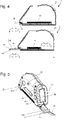
- FIG 3 1 is a view of the tape measure 1 from FIG figure 1 shown from below and with the housing 20 open on one side.
- the half-open housing shows how a clamping and measuring device 50 that can be extended from the housing 20 moves from a first position a to a second position b, with both positions of the clamping and measuring device 50 are shown and thereby spatially overlap.
- a thumb rocker 55 appears in the half-opened housing 20, which is part of a thumb-operated tape measure brake 53, which locks the tape measure 30 pulled out of the housing 20 and locks it against the restoring force of a coil spring to retract the tape measure 30.
- the thumb rocker 55 can also perform other, cumulative or alternative functions, such as serving as a control element for electronic navigation through a graphical operating system of an electronic reading device 80 .
- FIG 4 the silhouette of the housing 20 of the tape measure 1 is shown, in which the extendable from the housing 20 tensioning and measuring device 50 is shown together with a tension spring 70.
- the clamping and measuring device 50 that can be extended out of the housing 20 can be moved from a first position a (retracted state) into a second position b (extended state). and locked in these positions, but at least fixed by a locking device.
- the tension spring 70 is lengthened and tensioned, and in the extended state of the tensioning and measurement device 50 that can be extended from the housing 20, the tension spring 70 is less tensioned and short.
- the path of the clamping and measuring device 50 which can be extended from the housing 20, is indicated by the double arrow between the first position a and the second position b in both drawings, figure 4 above and figure 4 illustrated below, with the tension spring 70 relaxing when the clamping and measuring device 50 is extended.
- the different positions a and b result in different contact positions and reading edges, which are advantageous depending on the type of use. It is possible to use the reading edge 52 on the front edge of the clamping and measuring device 50 in the retracted state a, with an automatic switch or a manual switch, such as the operating buttons 81, 82, and 83, the electronic reading device 80 together with the Display device 100 configured so that the level of this reading edge 52 is displayed in the retracted state a.
- the reading edge 52 on the front edge of the clamping and measuring device 50 in the extended state b can be used with an automatic switch or a manual switch, such as the operating buttons 81, 82, and 83, the electronic reading device 80 configured together with the display device 100 in such a way that the dimension is displayed at this reading edge 52 in the extended state b.
- a manual switch such as the operating buttons 81, 82, and 83, can also be set so that the dimension is displayed on the reading edge 52b on the rear edge of the clamping and measuring device 50 in the extended state b.
- the electronic reading device 80 together with the display device 100 can also be configured by the same operating buttons 81, 82 and 83 or by another switch so that the dimension at the rear 85 of the housing 20 is displayed.
- FIG 5 14 is a rear perspective view of the tape measure 1 in FIG 1 shown in a first typical application.
- the rear view of the tape measure 1 reveals the buttons that can be operated with the fingers of the right hand. However, these keys can also be operated very well with the thumb of the left hand.
- These control buttons 81, 82, 83 for an electronic reading device 80 inside the housing can be freely configured and each can be assigned 2 functions.
- the tensioning and measuring device 50 which can be extended from the housing 20, is used to apply the unrolled measuring tape 30 to the surface to be measured (the tape itself should not be tensioned with the hook).
- the dimension of the tensioned measuring tape 30 can be easily read with the tensioning and measuring device 50 that can be extended from the housing 20 .
- This perspective view also shows how the dimension can be read off the reading edge 52b on the rear edge of the clamping and measuring device 50 in the extended state b.
- FIG 6 a view of the inner details of the tape measure 1 according to the invention is shown, in which the front housing wall of the housing 20 has been removed and the tension spring 70 from the sketch in figure 6 has been removed.
- the electronic reading device 80 forwards the calculated measured value as a display value to a display device 100 (display), where it can be read by the user.
- the calculated measured value can also be sent to a remote receiver via a radio protocol, such as Blue-Tooth ® , where the calculated and transmitted measured value is included in a statistic, for example for quality control.
- An electronic switch in the housing 20 detects the extended state of the extendable clamping and measuring device 50 and forwards it to the electronic reading device 80, which in this state subtracts a predefined value from the measurement result in order to determine the position of the extendable clamping and measuring device Measuring device 50 to be considered in the measurement result.
- the predefined value can refer to the inside or outside edge of the hook (internal and external measurements) This can be selected and set in the menu.
- the thumb rocker 55 can be seen, which on the one hand can serve as a mechanical operating element of a thumb-operated measuring tape brake 53, but also as a rocker for navigating in a graphical operating system that is output on the display device 100 (display).
- the winding reel 32 and the thumb rocker 55 are removed so that the inner rear view of the operating buttons 81, 82, 83 can be seen.
- FIG 7 a second typical application of the tape measure 1 is shown.
- a waistband is tightened with the tensioning and measuring device 50, which is designed as a hook and can be extended out of the housing 20.
- the tensioning and measuring device 50 which is designed as a hook and can be extended out of the housing 20.
- the user holds the left part of a waistband with his left hand, for example, and the user holds the tape measure with his right hand in order to operate it by pressing a button.
- the measuring edge 52b is used as the reading edge. Since the right hand is now no longer free, the user can use the hook as a substitute for another finger to tighten the right part of the waistband and thus measure the size of the waistband for quality control or random checks.
- a left-handed person takes the measurement the other way around.
- the measurement of a waistband in large numbers can be carried out easily.
- Usual quantities for a quality controller can between 500 and 2,000 textiles that have to be measured per working day.
- the clamping and measuring device 50 designed as a hook 51 is designed to be so stable that it can absorb a tensile force of up to 5 kg (approx. 50 N) in order to withstand everyday measurements under time pressure with possibly rough treatment not to be destroyed.
- the illustrated embodiments of the tape measure have a "handedness". It is a right-hand version.
- the tape measure can also be designed as a mirror image for left-handers. This means that the tape measure shown here is optimized for use with the right hand, as shown in figure 7 is shown.
- a thumb-operated button, thumb rocker 55, measuring tape brake 53 and another finger-operated button 101 for locking the measuring tape and/or for reading a measured value using the electronic reading device 80 can be operated ergonomically, i.e. in one for the right or alternatively arranged on the surface 21 of the housing 20 in an arrangement optimized for the left hand.
- a further embodiment of the tape measure provides that it has a contactless charging device 110 for the electronic reading device 80 in the form of an inductively coupled current transmission.
Landscapes
- Physics & Mathematics (AREA)
- General Physics & Mathematics (AREA)
- Tape Measures (AREA)
- Force Measurement Appropriate To Specific Purposes (AREA)
Description
- Die Erfindung betrifft ein Rollmaßband, aufweisend ein Gehäuse, und ein ausziehbares Maßband, wobei das ausziehbare Maßband aus einem Gehäuseschlitz herausragt.
- Zum Messen von Maßen eines industriell hergestellten Produktes, beispielsweise in der Qualitätskontrolle, ist es notwendig, dieses entweder automatisiert oder manuell einzeln zu vermessen. Für die Qualitätskontrolle oder für die Stichprobenkontrolle wird jedes einzelne Produkt einer genauen, zerstörungsfreien Messung unterzogen und aus dem Verhalten des Messwertes über eine große Anzahl von vermessenen Produkten kann ein Rückschluss auf die die Produktion beeinflussende Faktoren gezogen werden. In der Textilindustrie, wo ein großer Anteil an manueller Fertigung herrscht, ist es sehr wichtig, das genaue Maß der hergestellten Textilien zu überprüfen, weil sich durch eine Vielzahl von nicht unbedingt stabilen Fertigungsfaktoren das tatsächliche Maß eines in Serie hergestellten Bekleidungsstücks ändern kann.
- In der US-Patentanmeldung
US 2008/0168674A1 wird ein Rollmaßband gelehrt, welches eine am vorderen Gehäuseteil ausklappbare Lupe aufweist, die über das ausgefahrene Maßband gelegt werden kann. Die Lupe hilft, mit einer Leselinie an der unteren Seite der Lupe das Maßband abzulesen. - In der
österreichischen Patentschrift Nr. 222494 - In der kanadischen Patent
CA 2 305 094 wird ein an einem Maßband eines Rollmaßbandes vorhandener Fingerschutz gelehrt, welcher aus dem Rollmaßbandgehäuse ausziehbar ist und mit dem Nullpunkt des Maßband mitlaufen kann, Der Fingerschutz bewahrt den Nutzer gegen Schnittwunden beim intensiven Gebrauch des Rollmaßbandes. - In dem deutsche Gebrauchsmuster
DE 20 2005 011 814 U1 wird ein elektronisches Rollmaßband offenbart, welches im Inneren des Gehäuses einen Strichcodeleser aufweist, der zum elektronischen Ablesen einen auf dem Maßband aufgedruckten Strichcode liest. - In der US-Patentanmeldung
US 2010/0275456A1 wird ein elektronisches Rollmaßband mit einem Maßband ohne Maßverkörperung offenbart. Das Maßband besteht aus einem sehr dünnen Draht, welches am Ende unterschiedliche Befestigungsköpfe aufweist, dem das Maßband an einem zu vermessenden Objekt befestigt werden kann. - Aufgabe der Erfindung ist es, ein Rollmaßband zum Einsatz in der Qualitätskontrolle und/oder in der Stichprobenkontrolle vorzuschlagen, mit dessen Hilfe eine große Anzahl von Messungen verlässlich und für den Nutzer einfach durchgeführt werden kann.
- Die erfindungsgemäße Aufgabe wird gelöst durch ein Rollmaßband mit den Merkmalen nach Anspruch 1. Weitere vorteilhafte Ausgestaltungen sind in den Unteransprüchen zu Anspruch 1 angegeben.
- Nach der Erfindung ist also vorgehsehen, dass das Rollmaßband eine Art Spann-und Messvorrichtung in Form eines Hakens aufweist, wobei die Spann-und Messvorrichtung Teil des Rollmaßbandes ist und nicht ein von diesem abtrennbares Zusatzelement ist. Dieser Haken dient einerseits als Hilfselement zum exakten Anlegen des Maßbandes auf das Messobjekt. Andererseits kann der Haken dazu verwendet werden, das zu vermessende textile Bekleidungsstück, wie zum Beispiel einen Hosenbund aber auch jede andere Form von Öffnungen in Kleidungsstücken zu spannen, um so eine gleichmäßige Messbedingung bei der Vermessung einer Vielzahl ähnlicher oder gleicher Kleidungsstücke zu gewährleisten, so dass der Haken dem Nutzer als zusätzlicher Finger zur Verfügung steht.
- Nach dem Gedanken der Erfindung ist vorgesehen, dass die Spann- und Messvorrichtung in Form eines Hakens ausgebildet ist und bevorzugt eine gerade Ablesekante aufweist. Durch die gerade Ablesekante wird das rein optische Auslesen des Messwertes durch das menschliche Auge erleichtert.
- Für eine industrielle Nutzung in der Qualitätskontrolle und zur Erfassung von möglichst vielen Messwerten in kurzer Zeit ist es vorgesehen, dass im Gehäuse des Rollmaßbandes eine elektronische Ablesevorrichtung zur elektronischen Ablesung der Maßskala vorhanden ist, welche über ein Anforderungssignal in Form eines Knopfdrucks auf einen elektrischen Schalter das Messergebnis über ein Funkprotokoll an einen entfernten Empfänger sendet.
- Um die verschiedenen Zustände des Rollmaßbandes zu berücksichtigen, ist vorgesehen, dass ein im Gehäuse vorhandener elektronischer Schalter den ausgefahrenen Zustand der ausfahrbaren Spann- und Messvorrichtung detektiert und an die elektronische Ablesevorrichtung weiterleitet, welche in diesem Zustand von Messergebnis einen vordefinierten Wert abzieht, um die Position der ausfahrbaren Spann- und Messvorrichtung beim Messergebnis zu berücksichtigen, wobei diese Messwertkorrektur wahlweise für Messungen an der Innen- und Außenkante der Spann- und Messvorrichtung durchführbar ist.
- Um die Messung, die an einen entfernten Empfänger gesendet wird, zu prüfen, kann ebenso eine elektronische Anzeigevorrichtung in der Oberfläche des Gehäuses vorhanden sein, die das Messergebnis anzeigt.
- Für eine ausreichende Stabilität zum industriellen Einsatz sollte die als Haken ausgebildete Spann- und Messvorrichtung so stabil ausgelegt ist, dass diese eine Zugkraft von bis zu 5 kg (ca. 50 N), in besonderer Ausführungsform sogar 10 kg (ca. 100 N) und noch mehr aufnehmen kann. Das hat zur Folge, dass die Spann-und Messvorrichtung nicht abreißt.
- Für eine besonders ergonomische Gestaltung des Rollmaßbandes ist vorgesehen, dass ein daumenbetätigbarer Knopf zum Feststellen des Maßbandes in dem Rollmaßband vorhanden ist.
- Im Rollmaßband kann das Maßband eine optische Codierung zur elektronischen Auslesung aufweisen, wobei die optische Codierung ein absolutes Maß aufweist, also die Codierung an jeder Stelle des Maßbandes so aufgebaut ist, dass aus dieser an der jeweiligen Stelle das absolute Maß des Maßbandes auslesbar ist, wobei die Codierung beispielsweise ausgesucht sein kann aus der Gruppe bestehend aus: optischer Taktschrift, Maßverkörperung im Noniusverfahren durch zwei mit unterschiedlicher Frequenz nebeneinander angeordneten Maßverkörperungen, Barcode und inkrementeller Code, der durch Mitzählen beim Ausfahren auf das richtige Maß schließen lässt. Es kommen also auch andere, optische maschinenlesbare Codierungen mit einer Absolutmaßcodierung in Frage. So kann die Maßverkörperung auch nicht als Absolutmaß aufgebaut werden. In diesem Fall zählt ein Detektor den Durchgang von optischen Markierungen und zählt den Vorwärts- oder Rückwärtsdurchgang der optischen Markierungen und errechnet somit die aktuelle Maßposition. Durch den absoluten Code ist es für den Anwender leicht möglich das Maßband zu kalibrieren. Hierzu benötigt der Anwender nur eine Art Referenzmeter den er mit dem Maßband abmisst. Zum Eichen durch eine dazu befähigte Amtsperson kann entsprechend vorgegangen werden.
- Für einen komplikationslosen Einsatz kann vorgesehen sein, dass das Rollmaßband eine kontaktlose Aufladevorrichtung für die elektronische Ablesevorrichtung in Form einer induktiv gekoppelten Stromübertragung aufweist.
- Zur Kontrolle der Durchführung des Messvorgangs ist in weiterer Ausgestaltung der Erfindung vorgesehen, dass das elektronische Rollmaßband eine elektronische Wasserwaage aufweist.
- Je nach Einsatzart kann es von Vorteil sein, wenn Spann- und Messvorrichtung dauerhaft im ausgefahrenen Zustand dauerhaft arretierbar ist. In diesem Fall kann die Spann- und Messvorrichtung entweder beim erstmaligen Nutzen herausgezogen werden und danach durch die Arretierung nicht mehr eingefahren werden oder aber bereits in der Fertigung dauerhaft arretiert werden. Diese Festarretierung ist dann sinnvoll, wenn die verschiedenen Maßfunktionen auf eine Maßfunktion reduziert werden soll, um Schulungsarbeiten zum Umgang mit dem elektronischen Maßband zu vereinfachen.
- Die Erfindung wird anhand der folgenden Figuren näher erläutert. Es zeigt:
- Fig. 1
- zwei benachbarte Ansichten des erfindungsgemäßen Rollmaßbandes, wobei die linke Zeichnung eine ausfahrbare Spann- und Messvorrichtung im eingefahrenen Zustand und die rechte Zeichnung eine ausfahrbare Spann- und Messvorrichtung im ausgefahrenen Zustand zeigt,
- Fig. 2
- eine Maßskala und eine optische Codierung auf dem Maßband des Rollmaßbandes aus
Fig. 1 , - Fig. 3
- eine Ansicht auf das Rollmaßband aus
Figur 1 von unten, mit halbseitig geöffnetem Gehäuse, - Fig. 4
- eine Ansicht auf eine Federmechanik zum Ein- und Ausfahren der ausfahrbaren Spann- und Messvorrichtung,
- Fig. 5
- eine perspektivische Rückseitenansicht des Rollmaßbandes aus
Fig. 1 in einer ersten typischen Anwendungsart, - Fig. 6
- zwei Ansichten auf Details des Inneren des Rollmaßbandes aus
Fig. 1 , - Fig. 7
- eine Skizze einer zweiten Nutzungsart des Rollmaßbandes aus
Fig. 1 , der eigentlichen Hauptanwendung). - In
Figur 1 ist ein erfindungsgemäßes Rollmaßband 1 in zwei benachbarte Ansichten des dieses Rollmaßbandes 1 dargestellt. Das Rollmaßband 1 weist ein Gehäuse 20 und ein ausfahrbares Maßband 30 auf, wobei das ausfahrbare Maßband 30, aus einem Gehäuseschlitz 40 herausragt. Nach dem Gedanken der Erfindung ist vorgesehen, dass eine aus dem Gehäuse 20 ausfahrbare Spannund Messvorrichtung 50 von einem eingefahrenen Zustand (linke Zeichnung), wie es durch den ersten Pfeil links dargestellt ist, in einen ausgefahrenen Zustand (rechte Zeichnung), wie es durch den rechten Pfeil dargestellt ist, wechseln kann. - Die aus dem Gehäuse 20 ausfahrbare Spann- und Messvorrichtung 50 ist im ausgefahrenen Zustand (rechte Zeichnung) vor dem Gehäuseschlitz 40 angeordnet und dient dabei in einer ersten Nutzungsart als Spann- und Messvorrichtung 50 zum exakten Anlegen an einen Messpunkt an dem zu vermessenden Produkt.
- Die aus dem Gehäuse 20 ausfahrbare Spann- und Messvorrichtung 50 hilft durch ihre Form bei einem genauen Anlegen und auch Ablesen des Maßbandes 30.
- Um zu vermeiden, dass sich die Spann- und Messvorrichtung 50 bei Nichtgebrauch verfängt, womöglich beim Tragen in der Hosentasche sticht oder bei Einsatz im Textilbereich sogar Schäden an zu verarbeitenden Stoffen durch gezogene Fäden verursacht, ist vorgesehen, dass die aus dem Gehäuse 20 ausfahrbare Spann- und Messvorrichtung 50 ein- und wieder ausfahrbar ist.
- In der hier dargestellten Ausführungsform ist das Rollmaßband als elektronisches Rollmaßband ausgeführt. Neben den bereits erwähnten Elementen, weist das elektronische Rollmaßband 1 auch noch eine Anzeigevorrichtung 100 (Display) auf, auf dem der aktuelle Messwert, der durch die aus dem Gehäuse 20 ausfahrbare Spann- und Messvorrichtung 50 auf dem Maßband 30 eingestellt ist, abgelesen werden kann. Zum elektronischen Ablesen ist auf der Rückseite des Maßbandes 30 eine optische Codierung 31 aufgedruckt, die im Inneren des Rollmaßbandes 1 durch einen optischen Sensor 33 abgelesen und an eine elektronische Messeinrichtung 34 weitergeleitet wird. Diese interpretiert die optische Codierung 31, errechnet daraus einen Messwert und leitet diese an die Anzeigevorrichtung 100 zur Anzeige des Messwertes weiter.
- Die Maßskala 60 auf der Front des Maßbandes 30 ist auf der linken Seite von
Figur 2 abgebildet, wobei es auch möglich ist, dass keine für den Menschen ablesbare Skala erwünscht ist und daher nicht vorhanden ist. Eine auf der Rückseite des Maßbandes 30 vorhandene Maßverkörperung 35 oder ein Barcode 36 sind dazu korrespondierend auf der mittleren und rechten Seite vonFigur 2 dargestellt. Eine optische Codierung des Maßbandes 30 kann in Form einer optischen Taktschrift vorhanden sein, als Maßverkörperung 35 im Noniusverfahren mit zwei mit unterschiedlicher Frequenz nebeneinander angeordneten Maßverkörperungen (Figur 2 , Mitte) oder als Barcode 36. - (
Figur 2 , rechts). Schließlich kann eine Codierung auch sequentiell aufgebaut sein, wobei ein Detektor den Durchgang einer Codierung zählt und daraus die Maßposition des Maßbandes 30 rechnerisch ermittelt. - In
Figur 3 ist eine Ansicht auf das Rollmaßband 1 ausFigur 1 von unten und mit halbseitig geöffnetem Gehäuse 20 dargestellt. Durch das halbseitig geöffnete Gehäuse ist sichtbar, wie sich eine aus dem Gehäuse 20 ausfahrbare Spann-und Messvorrichtung 50 von einer ersten Position a in eine zweite Position b bewegt, wobei in dieser Skizze beide Stellungen der aus dem Gehäuse 20 ausfahrbare Spann- und Messvorrichtung 50 dargestellt sind und sich dadurch räumlich überlappen. In dem halbseitige geöffneten Gehäuse 20 kommt eine Daumenwippe 55 zum Vorschein, die Teil einer daumenbetätigbaren Maßbandbremse 53 ist, welche das aus dem Gehäuse 20 ausgezogene Maßband 30 feststellt und gegen die Rückstellkraft einer Wickelfeder zum Einzug des Maßbandes 30 arretiert. Die Daumenwippe 55 kann dabei aber noch andere, kumulative oder alternative Funktionen ausführen, wie zum Beispiel als Bedienungselement für eine elektronische Navigation durch ein grafisches Betriebssystem einer elektronischen Ablesevorrichtung 80 zu dienen. - In
Figur 4 ist die Silhouette des Gehäuses 20 des Rollmaßbandes 1 dargestellt, in welche die aus dem Gehäuse 20 ausfahrbare Spann- und Messvorrichtung 50 zusammen mit einer Zugfeder 70 eingeblendet ist. Die aus dem Gehäuse 20 ausfahrbare Spann- und Messvorrichtung 50 ist dabei von einer ersten Position a (eingefahrener Zustand) in eine zweite Position b (ausgefahrener Zustand) bewegbar und in diesen Positionen arretierbar, zumindest aber durch eine Rastvorrichtung fixiert. Im eingefahrenen Zustand (Figur 4 oben) der aus dem Gehäuse 20 ausfahrbare Spann- und Messvorrichtung 50 ist die Zugfeder 70 gelängt und gespannt, und im ausgefahrenen Zustand der aus dem Gehäuse 20 ausfahrbare Spann- und Messvorrichtung 50 ist die Zugfeder 70 geringer gespannt und kurz. Der Weg der aus dem Gehäuse 20 ausfahrbare Spann- und Messvorrichtung 50 ist durch den Doppelpfeilzwischen der ersten Position a und der zweiten Position b in beiden Zeichnungen,Figur 4 oben undFigur 4 unten verdeutlicht, wobei sich die Zugfeder 70 beim Ausfahren der Spann- und Messvorrichtung 50 entspannt. Durch die unterschiedlichen Positionen a und b ergeben sich unterschiedliche Anlagepositionen und Ablesekanten, die je nach Einsatzart von Vorteil sind. Es ist möglich, die Ablesekante 52 an der Vorderkante der Spann- und Messvorrichtung 50 im eingefahrenen Zustand a zu nutzen, wobei ein automatischer Umschalter oder ein manueller Umschalter, wie zum Beispiel die Bedienungstasten 81, 82, und 83, die elektronische Ablesevorrichtung 80 mitsamt der Anzeigevorrichtung 100 so konfiguriert, dass das Maß an dieser Ablesekante 52 im eingefahrenen Zustand a angezeigt wird. Es ist auch möglich, dass die Ablesekante 52 an der Vorderkante der Spann- und Messvorrichtung 50 im ausgefahrenen Zustand b zu nutzen, wobei ein automatischer Umschalter oder ein manueller Umschalter, wie zum Beispiel die Bedienungstasten 81, 82, und 83, die elektronische Ablesevorrichtung 80 mitsamt der Anzeigevorrichtung 100 so konfiguriert, dass das Maß an dieser Ablesekante 52 im ausgefahrenen Zustand b angezeigt wird. Durch einen manuellen Umschalter, wie zum Beispiel die Bedienungstasten 81, 82, und 83, kann auch eingestellt werden, dass das Maß an der Ablesekante 52b an der Rückseitenkante der Spann- und Messvorrichtung 50 im ausgefahrenen Zustand b angezeigt wird. Durch die gleichen die Bedienungstasten 81, 82, und 83 oder durch einen anderen Schalter kann die elektronische Ablesevorrichtung 80 mitsamt der Anzeigevorrichtung 100 auch so konfiguriert werden, dass das Maß an dem Heck 85 des Gehäuses 20 angezeigt wird. - In
Figur 5 ist eine perspektivische Rückseitenansicht des Rollmaßbandes 1 ausFig. 1 in einer ersten typischen Anwendungsart dargestellt. Die Rückseitenansicht des Rollmaßbandes 1 gibt die Sicht frei auf mit den Fingern der rechten Hand bedienbare Tasten. Allerdings können diese Tasten auch sehr gut mit dem Daumen der linken Hand bedient werden. Diese Bedienungstasten 81, 82, 83 für eine elektronische Ablesevorrichtung 80 im Inneren des Gehäuses sind frei konfigurierbar und jeweils mit 2 Funktionen belegbar. In dieser ersten typischen Anwendungsart wird die aus dem Gehäuse 20 ausfahrbare Spann- und Messvorrichtung 50 dazu verwendet, das ausgerollte Maßband 30 auf die zu vermessende Oberfläche anzulegen (das Band an sich soll nicht mit dem Haken gespannt werden). Das Maß des gespannten Maßbandes 30 kann mit der aus dem Gehäuse 20 ausfahrbare Spann- und Messvorrichtung 50 bequem abgelesen werden. In dieser perspektivischen Ansicht ist auch erkennbar, wie die das Maß an der Ablesekante 52b an der Rückseitenkante der Spann- und Messvorrichtung 50 im ausgefahrenen Zustand b ablesbar ist. - In
Figur 6 ist eine Ansicht auf die inneren Details des erfindungsgemäßen Rollmaßbandes 1 gezeigt, in dem die vordere Gehäusewand des Gehäuses 20 abgenommen ist und die Zugfeder 70 aus der Skizze inFigur 6 entfernt worden ist. Im inneren des Rollmaßbandes 1 befindet sich, wie in der oberen Skizze von Figur 6 dargestellt, eine Wickelspule 32 für das Maßband 30, wobei das Maßband 30 zwischen Wickelspule 32 und dem Gehäuseschlitz 40 durch eine optischen Sensor 33 geführt ist, der eine auf der Rückseite des Maßbandes 30 aufgedruckte, optische Codierung 31 liest und diese an eine elektronische Ablesevorrichtung 80 weiterleitet, welche den detektierten optischen Code interpretiert und daraus einen Messwert errechnet. Die elektronische Ablesevorrichtung 80 leitet den errechneten Messwert als Anzeigewert an eine Anzeigevorrichtung 100 (Display) weiter, wo es vom Anwender abgelesen werden kann. Auf Knopfdruck kann der errechnete Messwert auch über ein Funkprotokoll, wie zum Beispiel über Blue-Tooth®, an einen entfernten Empfänger geleitet werden, wo der ermittelte und übermittelte Messwert in eine Statistik zum Beispiel zur Qualitätskontrolle eingeht. Es ist vorgesehen, dass ein im Gehäuse 20 vorhandener elektronischer Schalter den ausgefahrenen Zustand der ausfahrbaren Spann- und Messvorrichtung 50 detektiert und an die elektronische Ablesevorrichtung 80 weiterleitet, welche in diesem Zustand von Messergebnis einen vordefinierten Wert abzieht, um die Position der ausfahrbaren Spann- und Messvorrichtung 50 beim Messergebnis zu berücksichtigen. Der vordefinierte Wert kann sich je nach Anwendungsfall auf die Innen- oder Außenkante des Hakens beziehen (Innen- und Außenmessungen) Das kann im Menü ausgewählt und eingestellt werden. In der oberen Skizze vonFigur 6 ist die Daumenwippe 55 zu erkennen, die einerseits als mechanisches Bedienungselement einer daumenbetätigbaren Maßbandbremse 53 dienen kann, aber auch als Wippe zur Navigation in einem grafischen Betriebssystem, das auf der Anzeigevorrichtung 100 (Display) ausgegeben wird. In der unteren Skizze vonFigur 6 ist die Wickelspule 32 und die Daumenwippe 55 entfernt, so dass die innere Rückseitenansicht auf die Bedienungsknöpfe 81, 82, 83 erkennbar ist. - In
Figur 7 ist schließlich eine zweite typische Anwendungsart des Rollmaßbandes 1 gezeigt. Mit der als Haken ausgebildeten, aus dem Gehäuse 20 ausfahrbaren Spann- und Messvorrichtung 50 wird ein Hosenbund gespannt. Zum Messen hält der Nutzer z.B. den linken Teil eines Hosenbundes mit der linken Hand fest und mit der rechten Hand hält der Nutzer das Rollmaßband, um es durch Knopfdrücken zu bedienen. In diesem Fall wird die Messkante 52b als Ablesekante verwendet. Da die rechte Hand nun nicht mehr frei ist, kann der Nutzer mit dem Haken als Ersatz für einen weiteren Finger den rechten Teil des Hosenbundes spannen und so das Maß des Hosenbundes zur Qualitätskontrolle oder zur Stichprobenkontrolle messen. Ein Linkshänder führt die Messung entsprechend anders herum durch. Auf diese Weise ist die Maßabnahme eines Hosenbundes in großer Zahl, wie sie in der Textilproduktion für einen Qualitätskontrolleur üblich ist, bequem durchführbar. Übliche Mengen für einen Qualitätskontrolleuer können zwischen 500 und 2.000 Textilien liegen, die pro Arbeitstag vermessen werden müssen. Für diese Anwendungsart ist vorgesehen, dass die als Haken 51 ausgebildete Spann- und Messvorrichtung 50 so stabil ausgelegt ist, dass diese eine Zugkraft von bis zu 5 kg (ca. 50 N) aufnehmen kann, um beim hektischen Messen unter Zeitdruck mit gegebenenfalls rauer Behandlung nicht zerstört zu werden. - Die dargestellten Ausführungsformen des Rollmaßbandes weisen eine "Händigkeit" auf. Es ist eine Rechtshänder-Ausführung. Das Rollmaßband kann auch spiegelverkehrt als Linkshänder-Ausführung aufgebaut sein. Das bedeutet, das hier gezeigte Rollmaßband ist für die Nutzung der rechten Hand optimiert, wie es in
Figur 7 dargestellt ist. Nach einem weiteren Gedanken der Erfindung ist vorgesehen, dass ein daumenbetätigbarer Knopf, Daumenwippe 55, Maßbandbremse 53 und ein weiterer, fingerbetätigbarer Knopf 101 zum Feststellen des Maßbandes und/oder zum Ablesen eines Messwertes durch die elektronische Ablesevorrichtung 80 ergonomisch, also in einer für die rechte oder alternativ für die linke Hand optimierten Anordnung auf der Oberfläche 21 des Gehäuses 20 angeordnet sind. Für einen industriellen Einsatz ist in weiterer Ausführungsform des Rollmaßbandes vorgesehen, dass dieses eine kontaktlose Aufladevorrichtung 110 für die elektronische Ablesevorrichtung 80 in Form einer induktiv gekoppelten Stromübertragung aufweist. -
- 1
- Rollmaßband
- 20
- Gehäuse
- 21
- Oberfläche
- 30
- Maßband
- 31
- Optische Codierung
- 32
- Wickelspule
- 33
- Optischer Sensor
- 34
- Elektronische Messeinrichtung
- 35
- Maßverkörperung
- 36
- Barcode
- 40
- Gehäuseschlitz
- 50
- Spann- und Messvorrichtung
- 51
- Haken
- 52
- Ablesekante
- 52b
- Ablesekante
- 53
- Maßbandbremse
- 55
- Daumenwippe
- 60
- Maßskala
- 70
- Zugfeder
- 80
- Elektronische Ablesevorrich-tung
- 81
- Bedienungstaste
- 82
- Bedienungstaste
- 83
- Bedienungstaste
- 85
- Heck
- 100
- Anzeigevorrichtung (Display)
- 101
- Fingerbetätigbarer Knopf
- 110
- Kontaktlose Aufladevorrich-tung
- a
- Erste Position
- b
- Zweite Position
Claims (8)
- Rollmaßband (1), aufweisend- ein Gehäuse (20), und- ein ausziehbares Maßband (30),wobei das ausziehbare Maßband (30) dazu ausgebildet ist aus einem Gehäuseschlitz (40) herauszuragen,wobei eine aus dem Gehäuse (20) ausfahrbare Spann- und Messvorrichtung (50) vorhanden ist,welche im ausgefahrenen Zustand vor dem Gehäuseschlitz (40) angeordnet ist und als Spann- und Messvorrichtung zum exakten Ablesen einer Maßskala (60) auf dem Maßband (30) und/oder zum Spannen eines Messprüflings dient, wobeidie Spann- und Messvorrichtung (50) in Form eines Hakens (51) ausgebildet ist und bevorzugt eine gerade Ablesekante (52) aufweist, und wobei im Gehäuse (20) eine elektronische Ablesevorrichtung (80) zur elektronischen Ablesung der Maßskala (60) vorhanden ist, welche dazu ausgebildet ist über ein Anforderungssignal in Form eines Knopfdrucks auf einen elektrischen Schalter (81, 82, 83) das Messergebnis über ein Funkprotokoll an einen entfernten Empfänger zu senden,wobei die elektronische Ablesevorrichtung (80) kalibrierbar und/oder eichfähig ist, und wobeiein im Gehäuse (20) vorhandener elektronischer Schalter dazu ausgebildet ist den ausgefahrenen Zustand der ausfahrbaren Spann- und Messvorrichtung (50) zu detektierenund an die elektronische Ablesevorrichtung (80) weiterzuleiten, welche dazu ausgebildet ist in diesem Zustand vom Messergebnis einen vordefinierten Wert abzuziehen, um die Position der ausfahrbaren Spann- und Messvorrichtung (50) beim Messergebnis zu berücksichtigen, wobei diese Messwertkorrektur wahlweise für Messungen an der Innen- und Außenkante der Spann- und Messvorrichtung (50) durchführbar ist.
- Rollmaßband nach Anspruch 1,
dadurch gekennzeichnet, dass
eine elektronische Anzeigevorrichtung (100) in der Oberfläche (21) des Gehäuses (20) dazu ausgebildet ist das Messergebnis anzuzeigen. - Rollmaßband nach Anspruch 1 oder 2 ,
dadurch gekennzeichnet, dass
die als Haken (51) ausgebildete Spann- und Messvorrichtung (50) so stabil ausgelegt ist, dass diese eine Zugkraft von bis zu 5 kg (ca. 50 N) aufnehmen kann. - Rollmaßband nach einem der Ansprüche 1 bis 3,
dadurch gekennzeichnet, dass
das Maßband (30) eine optische Codierung (31) zur elektronischen Auslesung aufweist, wobei die optische Codierung (31) ein absolutes Maß aufweist, also die Codierung (31) an jeder Stelle des Maßbandes (30) so aufgebaut ist, dass aus dieser an der jeweiligen Stelle das absolute Maß des Maßbandes (30) auslesbar ist, wobei die Codierung (31) ausgesucht ist aus der Gruppe bestehend aus: optischer Taktschrift, Maßverkörperung im Noniusverfahren durch zwei mit unterschiedlicher Frequenz nebeneinander angeordneten Maßverkörperungen, Barcode, inkrementeller Code, der durch Mitzählen beim Ausfahren auf das richtige Maß schließen lässt. - Rollmaßband nach einem der Ansprüche 1 bis 4,
dadurch gekennzeichnet, dass
dieses eine kontaktlose Aufladevorrichtung (110) für die elektronische Ablesevorrichtung (80) in Form einer induktiv gekoppelten Stromübertragung aufweist. - Rollmaßband nach einem der Ansprüche 1 bis 5,
dadurch gekennzeichnet, dass
dieses eine elektronische Wasserwaage aufweist. - Rollmaßband nach einem der Ansprüche 1 bis 6,
dadurch gekennzeichnet, dass
über mindestens einen elektronischen Schalter (81, 82, 83) eine Aufnahme des Maßes von bis zu vier unterschiedlichen Anlagepositionen einstellbar ist, wobei diese Anlagepositionen an folgenden Positionen vorhanden sind:- Ablesekante (52) an der Vorderkante der Spann- und Messvorrichtung (50) im eingefahrenen Zustand (a),- Ablesekante (52) an der Vorderkante der Spann- und Messvorrichtung (50) im ausgefahrenen Zustand (b),- Ablesekante (52b) an der Rückseitenkante der Spann- und Messvorrichtung (50) im ausgefahrenen Zustand (b),- Anlageposition am Heck (85) des Gehäuses (20). - Rollmaßband nach einem der Ansprüche 1 bis 7,
dadurch gekennzeichnet, dass die Spann- und Messvorrichtung (50) dauerhaft im ausgefahrenen Zustand arretierbar ist.
Applications Claiming Priority (2)
| Application Number | Priority Date | Filing Date | Title |
|---|---|---|---|
| DE102018116482.3A DE102018116482B4 (de) | 2018-07-06 | 2018-07-06 | Rollmaßband mit ausfahrbarer Spann- und Messvorrichtung |
| PCT/IB2019/055093 WO2020008286A1 (de) | 2018-07-06 | 2019-06-18 | ROLLMAßBAND MIT AUSFAHRBARER SPANN- UND MESSVORRICHTUNG |
Publications (2)
| Publication Number | Publication Date |
|---|---|
| EP3818328A1 EP3818328A1 (de) | 2021-05-12 |
| EP3818328B1 true EP3818328B1 (de) | 2022-03-30 |
Family
ID=67841106
Family Applications (1)
| Application Number | Title | Priority Date | Filing Date |
|---|---|---|---|
| EP19762457.0A Active EP3818328B1 (de) | 2018-07-06 | 2019-06-18 | Rollmassband mit ausfahrbarer spann- und messvorrichtung |
Country Status (5)
| Country | Link |
|---|---|
| US (1) | US11359903B2 (de) |
| EP (1) | EP3818328B1 (de) |
| CN (1) | CN112424558B (de) |
| DE (1) | DE102018116482B4 (de) |
| WO (1) | WO2020008286A1 (de) |
Families Citing this family (4)
| Publication number | Priority date | Publication date | Assignee | Title |
|---|---|---|---|---|
| DE102018116482B4 (de) * | 2018-07-06 | 2020-01-23 | Hoechstmass Balzer Gmbh | Rollmaßband mit ausfahrbarer Spann- und Messvorrichtung |
| US11378376B2 (en) * | 2019-11-08 | 2022-07-05 | Kevin P. Terry | System and method for using a digital measuring device to install a structure |
| USD980727S1 (en) * | 2022-10-20 | 2023-03-14 | Reestar International Limited | Electronic tape measure |
| DE102024110518A1 (de) * | 2024-04-15 | 2025-10-16 | Hoechstmass Balzer Gmbh | Elektronisches Rollmaßband |
Citations (1)
| Publication number | Priority date | Publication date | Assignee | Title |
|---|---|---|---|---|
| US20040172839A1 (en) * | 2003-03-03 | 2004-09-09 | Zirk Jason E. | Multi-use tool |
Family Cites Families (34)
| Publication number | Priority date | Publication date | Assignee | Title |
|---|---|---|---|---|
| US2022756A (en) * | 1933-09-30 | 1935-12-03 | Lufkin Rule Co | Tape measure |
| AT222494B (de) * | 1959-12-05 | 1962-07-25 | Agfa Ag | An einer photographischen Kamera angeordnetes, aufrollbares Maßband |
| GB2183951B (en) * | 1985-11-28 | 1990-05-23 | Duracell Int | Displacement measuring apparatus |
| GB2241060B (en) * | 1990-02-20 | 1993-06-16 | Liebermann Arax Ltd | Tape measure |
| CN2136455Y (zh) * | 1992-10-14 | 1993-06-16 | 关铁梁 | 精密游标卷尺 |
| US5433014A (en) * | 1994-09-19 | 1995-07-18 | Falk; David C. | Digital tape rule with transmitter |
| GB9826235D0 (en) * | 1998-11-30 | 1999-01-20 | Hague Frank | Tape measures |
| US6349483B1 (en) * | 2000-03-14 | 2002-02-26 | Dennis M. Dodge, Sr. | Guide attachment for a measuring tape |
| CA2305094A1 (en) * | 2000-04-12 | 2001-10-12 | Jure Tomljenovic | Sliding finger protector for tape measures |
| US6497050B1 (en) * | 2000-04-28 | 2002-12-24 | Paul Ricalde | Tape measure apparatus which can be used as a marking gauge and/or compass |
| US6996915B2 (en) * | 2000-04-28 | 2006-02-14 | Paul Ricalde | Tape measure apparatus which can be used as a marking gauge and/or compass |
| US6536698B2 (en) * | 2001-08-10 | 2003-03-25 | Cheng-Hui Hsu | Dual mode tape rule blade arrestor structure |
| US6938354B2 (en) * | 2002-02-21 | 2005-09-06 | Cole Scientific, Inc. | Measurement marking, scribing and scoring device |
| CN2606328Y (zh) * | 2003-03-22 | 2004-03-10 | 逄海水 | 自检式符合工程卷尺 |
| US6976318B2 (en) * | 2003-06-16 | 2005-12-20 | Mark Odachowski | Tape measure |
| CN2672615Y (zh) * | 2003-12-29 | 2005-01-19 | 谢瑞能 | 记忆多用卷尺 |
| CN2793681Y (zh) * | 2004-09-22 | 2006-07-05 | 许锋 | 多功能盒尺 |
| US7159332B2 (en) * | 2004-11-29 | 2007-01-09 | Sullivan Daniel B | Tape measure clip for improving measurement accuracy |
| DE202005011814U1 (de) * | 2005-07-25 | 2006-08-31 | Hoechstmass Balzer Gmbh | Elektronisches Maßband und dieses umfassende Längenmesseinrichtung |
| US7181860B1 (en) * | 2005-11-05 | 2007-02-27 | Kurt Franklyn Umholtz | Miter measuring tape |
| DE102006034644B4 (de) * | 2006-07-24 | 2010-12-09 | Soehnle Professional Gmbh & Co. Kg | Längenmesseinrichtung |
| US20080098610A1 (en) * | 2006-10-25 | 2008-05-01 | Daniel Lipps | Measurement marker |
| CN101191715A (zh) * | 2006-11-20 | 2008-06-04 | 朱四林 | 数显线卷尺 |
| US7584548B2 (en) * | 2007-01-16 | 2009-09-08 | Rob Nielson | Tape measure |
| JP3143409U (ja) * | 2008-05-09 | 2008-07-24 | ヤマヨ測定機株式会社 | デジタル表示式メジャー |
| JP4399840B2 (ja) * | 2009-02-02 | 2010-01-20 | 猛 阿部 | 内寸測定用治具付き巻尺 |
| US8356419B2 (en) | 2009-04-29 | 2013-01-22 | Peter Maxwell Lord | Digital measuring device |
| US7918037B1 (en) * | 2010-03-05 | 2011-04-05 | Nikolay Polkhovskiy | Tape measure endpiece |
| WO2012082034A1 (en) * | 2010-12-16 | 2012-06-21 | Viveta Ab | Accurate waist measurement |
| US20150089826A1 (en) * | 2013-09-27 | 2015-04-02 | Eduardo Villalpando | Measuring Tape |
| JP6540312B2 (ja) * | 2015-07-17 | 2019-07-10 | 日本製鉄株式会社 | 寸法測定装置 |
| US9778010B2 (en) * | 2015-08-31 | 2017-10-03 | Sears Brands, L.L.C. | Retractable tape measure and securing same |
| DE102018116482B4 (de) * | 2018-07-06 | 2020-01-23 | Hoechstmass Balzer Gmbh | Rollmaßband mit ausfahrbarer Spann- und Messvorrichtung |
| US11112227B1 (en) * | 2019-10-15 | 2021-09-07 | Gustavo Lopez | Tape measure attachment system |
-
2018
- 2018-07-06 DE DE102018116482.3A patent/DE102018116482B4/de active Active
-
2019
- 2019-06-18 EP EP19762457.0A patent/EP3818328B1/de active Active
- 2019-06-18 US US17/258,104 patent/US11359903B2/en active Active
- 2019-06-18 WO PCT/IB2019/055093 patent/WO2020008286A1/de not_active Ceased
- 2019-06-18 CN CN201980044692.0A patent/CN112424558B/zh active Active
Patent Citations (1)
| Publication number | Priority date | Publication date | Assignee | Title |
|---|---|---|---|---|
| US20040172839A1 (en) * | 2003-03-03 | 2004-09-09 | Zirk Jason E. | Multi-use tool |
Also Published As
| Publication number | Publication date |
|---|---|
| DE102018116482A1 (de) | 2020-01-09 |
| US20210278190A1 (en) | 2021-09-09 |
| US11359903B2 (en) | 2022-06-14 |
| EP3818328A1 (de) | 2021-05-12 |
| CN112424558B (zh) | 2023-09-01 |
| CN112424558A (zh) | 2021-02-26 |
| WO2020008286A1 (de) | 2020-01-09 |
| DE102018116482B4 (de) | 2020-01-23 |
Similar Documents
| Publication | Publication Date | Title |
|---|---|---|
| DE4322661C2 (de) | Bandmaßvorrichtung | |
| DE102018116482B4 (de) | Rollmaßband mit ausfahrbarer Spann- und Messvorrichtung | |
| DE3620723C2 (de) | Verfahren und digitales Meßgerät zum Anzeigen eines sich zeitlich ändernden Meßwertes | |
| EP0266713B1 (de) | Vorrichtung zum Messen von Distanzen an einem Werkstück, und für das digitale Messen solcher Distanzen eingerichtete Schiebelehre | |
| DE4213588A1 (de) | Dimensionsmessgeraet | |
| DE202005011814U1 (de) | Elektronisches Maßband und dieses umfassende Längenmesseinrichtung | |
| EP3150972B1 (de) | Elektronischer winkelsensor für zeigerinstrumente | |
| DE3432511C2 (de) | ||
| WO2005083465A1 (de) | Handgehaltene vorrichtung zum messen von distanzen | |
| DE2900040C2 (de) | Vorrichtung zum Messen der Tiefe von Laufflächenrillen in einem Luftreifen | |
| DE2025047B2 (de) | Lastmomentsicherung fuer auslegerkrane | |
| WO2019145501A1 (de) | Vorrichtung zum erfassen der bandspannung eines gurtbandes | |
| DE60035725T2 (de) | Elektronisches Messband | |
| EP1575859B1 (de) | Fadenmessgerät, insbesondere für instationäre anwendungen | |
| DE102018003288A1 (de) | Digitales Messinstrument und Betriebsmodus-Einstellverfahren dafür | |
| DE2846915C2 (de) | Rollbandmaß | |
| WO2012163921A1 (de) | Biegewinkelsensor | |
| DE598911C (de) | Pruefgeraet fuer Briefmarken | |
| DE102004055650B4 (de) | Vorrichtung zur elektronischen Erfassung von Maßen, insbesondere von Körpermaßen eines Patienten | |
| EP1661515A2 (de) | Vorrichtung zur elektronischen Erfassung von Massen, insbesondere von Körpermassen eines Patienten | |
| EP0998730A1 (de) | Gerät zum erfassen des wertes von münzen | |
| WO2025219791A1 (de) | ELEKTRONISCHES ROLLMAßBAND | |
| WO2002075239A1 (de) | Bandmessgerät zum abmessen einer länge einer strecke | |
| DE202012001642U1 (de) | Rollmaßband | |
| DE7813146U1 (de) | Vorrichtung zum messen des abstandes zwischen den giesstrang-stuetzrollen einer stranggiessanlage fuer stahl oder metall |
Legal Events
| Date | Code | Title | Description |
|---|---|---|---|
| STAA | Information on the status of an ep patent application or granted ep patent |
Free format text: STATUS: UNKNOWN |
|
| STAA | Information on the status of an ep patent application or granted ep patent |
Free format text: STATUS: THE INTERNATIONAL PUBLICATION HAS BEEN MADE |
|
| PUAI | Public reference made under article 153(3) epc to a published international application that has entered the european phase |
Free format text: ORIGINAL CODE: 0009012 |
|
| STAA | Information on the status of an ep patent application or granted ep patent |
Free format text: STATUS: REQUEST FOR EXAMINATION WAS MADE |
|
| 17P | Request for examination filed |
Effective date: 20210127 |
|
| AK | Designated contracting states |
Kind code of ref document: A1 Designated state(s): AL AT BE BG CH CY CZ DE DK EE ES FI FR GB GR HR HU IE IS IT LI LT LU LV MC MK MT NL NO PL PT RO RS SE SI SK SM TR |
|
| DAV | Request for validation of the european patent (deleted) | ||
| DAX | Request for extension of the european patent (deleted) | ||
| GRAP | Despatch of communication of intention to grant a patent |
Free format text: ORIGINAL CODE: EPIDOSNIGR1 |
|
| STAA | Information on the status of an ep patent application or granted ep patent |
Free format text: STATUS: GRANT OF PATENT IS INTENDED |
|
| INTG | Intention to grant announced |
Effective date: 20211203 |
|
| RIN1 | Information on inventor provided before grant (corrected) |
Inventor name: KREBS, KLAUS Inventor name: NEY, CARSTEN |
|
| GRAS | Grant fee paid |
Free format text: ORIGINAL CODE: EPIDOSNIGR3 |
|
| GRAA | (expected) grant |
Free format text: ORIGINAL CODE: 0009210 |
|
| STAA | Information on the status of an ep patent application or granted ep patent |
Free format text: STATUS: THE PATENT HAS BEEN GRANTED |
|
| AK | Designated contracting states |
Kind code of ref document: B1 Designated state(s): AL AT BE BG CH CY CZ DE DK EE ES FI FR GB GR HR HU IE IS IT LI LT LU LV MC MK MT NL NO PL PT RO RS SE SI SK SM TR |
|
| REG | Reference to a national code |
Ref country code: GB Ref legal event code: FG4D Free format text: NOT ENGLISH |
|
| REG | Reference to a national code |
Ref country code: CH Ref legal event code: EP |
|
| REG | Reference to a national code |
Ref country code: AT Ref legal event code: REF Ref document number: 1479567 Country of ref document: AT Kind code of ref document: T Effective date: 20220415 |
|
| REG | Reference to a national code |
Ref country code: DE Ref legal event code: R096 Ref document number: 502019003906 Country of ref document: DE |
|
| REG | Reference to a national code |
Ref country code: IE Ref legal event code: FG4D Free format text: LANGUAGE OF EP DOCUMENT: GERMAN |
|
| REG | Reference to a national code |
Ref country code: LT Ref legal event code: MG9D |
|
| PG25 | Lapsed in a contracting state [announced via postgrant information from national office to epo] |
Ref country code: SE Free format text: LAPSE BECAUSE OF FAILURE TO SUBMIT A TRANSLATION OF THE DESCRIPTION OR TO PAY THE FEE WITHIN THE PRESCRIBED TIME-LIMIT Effective date: 20220330 Ref country code: RS Free format text: LAPSE BECAUSE OF FAILURE TO SUBMIT A TRANSLATION OF THE DESCRIPTION OR TO PAY THE FEE WITHIN THE PRESCRIBED TIME-LIMIT Effective date: 20220330 Ref country code: NO Free format text: LAPSE BECAUSE OF FAILURE TO SUBMIT A TRANSLATION OF THE DESCRIPTION OR TO PAY THE FEE WITHIN THE PRESCRIBED TIME-LIMIT Effective date: 20220630 Ref country code: LT Free format text: LAPSE BECAUSE OF FAILURE TO SUBMIT A TRANSLATION OF THE DESCRIPTION OR TO PAY THE FEE WITHIN THE PRESCRIBED TIME-LIMIT Effective date: 20220330 Ref country code: HR Free format text: LAPSE BECAUSE OF FAILURE TO SUBMIT A TRANSLATION OF THE DESCRIPTION OR TO PAY THE FEE WITHIN THE PRESCRIBED TIME-LIMIT Effective date: 20220330 Ref country code: BG Free format text: LAPSE BECAUSE OF FAILURE TO SUBMIT A TRANSLATION OF THE DESCRIPTION OR TO PAY THE FEE WITHIN THE PRESCRIBED TIME-LIMIT Effective date: 20220630 |
|
| REG | Reference to a national code |
Ref country code: NL Ref legal event code: MP Effective date: 20220330 |
|
| PG25 | Lapsed in a contracting state [announced via postgrant information from national office to epo] |
Ref country code: LV Free format text: LAPSE BECAUSE OF FAILURE TO SUBMIT A TRANSLATION OF THE DESCRIPTION OR TO PAY THE FEE WITHIN THE PRESCRIBED TIME-LIMIT Effective date: 20220330 Ref country code: GR Free format text: LAPSE BECAUSE OF FAILURE TO SUBMIT A TRANSLATION OF THE DESCRIPTION OR TO PAY THE FEE WITHIN THE PRESCRIBED TIME-LIMIT Effective date: 20220701 Ref country code: FI Free format text: LAPSE BECAUSE OF FAILURE TO SUBMIT A TRANSLATION OF THE DESCRIPTION OR TO PAY THE FEE WITHIN THE PRESCRIBED TIME-LIMIT Effective date: 20220330 |
|
| PG25 | Lapsed in a contracting state [announced via postgrant information from national office to epo] |
Ref country code: NL Free format text: LAPSE BECAUSE OF FAILURE TO SUBMIT A TRANSLATION OF THE DESCRIPTION OR TO PAY THE FEE WITHIN THE PRESCRIBED TIME-LIMIT Effective date: 20220330 |
|
| PG25 | Lapsed in a contracting state [announced via postgrant information from national office to epo] |
Ref country code: SM Free format text: LAPSE BECAUSE OF FAILURE TO SUBMIT A TRANSLATION OF THE DESCRIPTION OR TO PAY THE FEE WITHIN THE PRESCRIBED TIME-LIMIT Effective date: 20220330 Ref country code: SK Free format text: LAPSE BECAUSE OF FAILURE TO SUBMIT A TRANSLATION OF THE DESCRIPTION OR TO PAY THE FEE WITHIN THE PRESCRIBED TIME-LIMIT Effective date: 20220330 Ref country code: RO Free format text: LAPSE BECAUSE OF FAILURE TO SUBMIT A TRANSLATION OF THE DESCRIPTION OR TO PAY THE FEE WITHIN THE PRESCRIBED TIME-LIMIT Effective date: 20220330 Ref country code: PT Free format text: LAPSE BECAUSE OF FAILURE TO SUBMIT A TRANSLATION OF THE DESCRIPTION OR TO PAY THE FEE WITHIN THE PRESCRIBED TIME-LIMIT Effective date: 20220801 Ref country code: ES Free format text: LAPSE BECAUSE OF FAILURE TO SUBMIT A TRANSLATION OF THE DESCRIPTION OR TO PAY THE FEE WITHIN THE PRESCRIBED TIME-LIMIT Effective date: 20220330 Ref country code: EE Free format text: LAPSE BECAUSE OF FAILURE TO SUBMIT A TRANSLATION OF THE DESCRIPTION OR TO PAY THE FEE WITHIN THE PRESCRIBED TIME-LIMIT Effective date: 20220330 Ref country code: CZ Free format text: LAPSE BECAUSE OF FAILURE TO SUBMIT A TRANSLATION OF THE DESCRIPTION OR TO PAY THE FEE WITHIN THE PRESCRIBED TIME-LIMIT Effective date: 20220330 |
|
| PG25 | Lapsed in a contracting state [announced via postgrant information from national office to epo] |
Ref country code: PL Free format text: LAPSE BECAUSE OF FAILURE TO SUBMIT A TRANSLATION OF THE DESCRIPTION OR TO PAY THE FEE WITHIN THE PRESCRIBED TIME-LIMIT Effective date: 20220330 Ref country code: IS Free format text: LAPSE BECAUSE OF FAILURE TO SUBMIT A TRANSLATION OF THE DESCRIPTION OR TO PAY THE FEE WITHIN THE PRESCRIBED TIME-LIMIT Effective date: 20220730 Ref country code: AL Free format text: LAPSE BECAUSE OF FAILURE TO SUBMIT A TRANSLATION OF THE DESCRIPTION OR TO PAY THE FEE WITHIN THE PRESCRIBED TIME-LIMIT Effective date: 20220330 |
|
| REG | Reference to a national code |
Ref country code: DE Ref legal event code: R097 Ref document number: 502019003906 Country of ref document: DE |
|
| PG25 | Lapsed in a contracting state [announced via postgrant information from national office to epo] |
Ref country code: MC Free format text: LAPSE BECAUSE OF FAILURE TO SUBMIT A TRANSLATION OF THE DESCRIPTION OR TO PAY THE FEE WITHIN THE PRESCRIBED TIME-LIMIT Effective date: 20220330 Ref country code: DK Free format text: LAPSE BECAUSE OF FAILURE TO SUBMIT A TRANSLATION OF THE DESCRIPTION OR TO PAY THE FEE WITHIN THE PRESCRIBED TIME-LIMIT Effective date: 20220330 |
|
| REG | Reference to a national code |
Ref country code: CH Ref legal event code: PL |
|
| PLBE | No opposition filed within time limit |
Free format text: ORIGINAL CODE: 0009261 |
|
| STAA | Information on the status of an ep patent application or granted ep patent |
Free format text: STATUS: NO OPPOSITION FILED WITHIN TIME LIMIT |
|
| REG | Reference to a national code |
Ref country code: BE Ref legal event code: MM Effective date: 20220630 |
|
| 26N | No opposition filed |
Effective date: 20230103 |
|
| PG25 | Lapsed in a contracting state [announced via postgrant information from national office to epo] |
Ref country code: LU Free format text: LAPSE BECAUSE OF NON-PAYMENT OF DUE FEES Effective date: 20220618 Ref country code: LI Free format text: LAPSE BECAUSE OF NON-PAYMENT OF DUE FEES Effective date: 20220630 Ref country code: IE Free format text: LAPSE BECAUSE OF NON-PAYMENT OF DUE FEES Effective date: 20220618 Ref country code: FR Free format text: LAPSE BECAUSE OF NON-PAYMENT OF DUE FEES Effective date: 20220630 Ref country code: CH Free format text: LAPSE BECAUSE OF NON-PAYMENT OF DUE FEES Effective date: 20220630 |
|
| PG25 | Lapsed in a contracting state [announced via postgrant information from national office to epo] |
Ref country code: SI Free format text: LAPSE BECAUSE OF FAILURE TO SUBMIT A TRANSLATION OF THE DESCRIPTION OR TO PAY THE FEE WITHIN THE PRESCRIBED TIME-LIMIT Effective date: 20220330 Ref country code: BE Free format text: LAPSE BECAUSE OF NON-PAYMENT OF DUE FEES Effective date: 20220630 |
|
| PG25 | Lapsed in a contracting state [announced via postgrant information from national office to epo] |
Ref country code: IT Free format text: LAPSE BECAUSE OF FAILURE TO SUBMIT A TRANSLATION OF THE DESCRIPTION OR TO PAY THE FEE WITHIN THE PRESCRIBED TIME-LIMIT Effective date: 20220330 |
|
| GBPC | Gb: european patent ceased through non-payment of renewal fee |
Effective date: 20230618 |
|
| PG25 | Lapsed in a contracting state [announced via postgrant information from national office to epo] |
Ref country code: MK Free format text: LAPSE BECAUSE OF FAILURE TO SUBMIT A TRANSLATION OF THE DESCRIPTION OR TO PAY THE FEE WITHIN THE PRESCRIBED TIME-LIMIT Effective date: 20220330 Ref country code: CY Free format text: LAPSE BECAUSE OF FAILURE TO SUBMIT A TRANSLATION OF THE DESCRIPTION OR TO PAY THE FEE WITHIN THE PRESCRIBED TIME-LIMIT Effective date: 20220330 Ref country code: GB Free format text: LAPSE BECAUSE OF NON-PAYMENT OF DUE FEES Effective date: 20230618 |
|
| PG25 | Lapsed in a contracting state [announced via postgrant information from national office to epo] |
Ref country code: HU Free format text: LAPSE BECAUSE OF FAILURE TO SUBMIT A TRANSLATION OF THE DESCRIPTION OR TO PAY THE FEE WITHIN THE PRESCRIBED TIME-LIMIT; INVALID AB INITIO Effective date: 20190618 |
|
| PG25 | Lapsed in a contracting state [announced via postgrant information from national office to epo] |
Ref country code: TR Free format text: LAPSE BECAUSE OF FAILURE TO SUBMIT A TRANSLATION OF THE DESCRIPTION OR TO PAY THE FEE WITHIN THE PRESCRIBED TIME-LIMIT Effective date: 20220330 |
|
| PG25 | Lapsed in a contracting state [announced via postgrant information from national office to epo] |
Ref country code: MT Free format text: LAPSE BECAUSE OF FAILURE TO SUBMIT A TRANSLATION OF THE DESCRIPTION OR TO PAY THE FEE WITHIN THE PRESCRIBED TIME-LIMIT Effective date: 20220330 |
|
| PGFP | Annual fee paid to national office [announced via postgrant information from national office to epo] |
Ref country code: DE Payment date: 20250623 Year of fee payment: 7 |
|
| REG | Reference to a national code |
Ref country code: AT Ref legal event code: MM01 Ref document number: 1479567 Country of ref document: AT Kind code of ref document: T Effective date: 20240618 |
|
| PG25 | Lapsed in a contracting state [announced via postgrant information from national office to epo] |
Ref country code: AT Free format text: LAPSE BECAUSE OF NON-PAYMENT OF DUE FEES Effective date: 20240618 |
|
| PGFP | Annual fee paid to national office [announced via postgrant information from national office to epo] |
Ref country code: AT Payment date: 20260410 Year of fee payment: 5 |